RN68 1 KAERl/CM-533/2001 Development of SMART Advanced Reactor Development of Basic Model for Seawater Desalination System . h I .

Welcome message from author
This document is posted to help you gain knowledge. Please leave a comment to let me know what you think about it! Share it to your friends and learn new things together.
Transcript

RN68 1
KAERl/CM-533/2001
Development of SMART Advanced Reactor
Development of Basic Model for Seawater Desalination System
.
h
I .

DlSCLAlMER
Portions of this document may be illegib'd in electronic image products. Images are produced from the best available original document.

I I
i I I I
I
KAERI/CM-533/2001
Development of SMART Advanced Reactor
.Development of Basic Model for Seawater Desalination System
J


I 1
I I
S U M M A R Y i 1 1
construction.
The production capacity of the SMART nuclear desal ination plant is
1. TITLE
f
j .
’ SMART Nuclear Desalination Plant Basic Design Development
11. OBJECTIVES AND NEEDS
The development of the integrated reactor (SMART) is different from the nuclear reactors which is under commercial operations at present. The goal
of the SMART nuclear seawater desalination plant is to develop a seawater desal ination plant which wi 11 produce 40,000m3 of potable water from
seawater di s t i 1 1 at i on.
.
I 111. SCOPE & CONTENTS
I The scope and contents of this report are: the stage-of-the-art report
for the desal ination processes, design requirements for the SMART
I desal ination plant, P&I diagrams, and general arrangement drawings, design specifications for the major equipment, the intermediate loop with the trubine (steam transformer), chemistry design guide.
IV. RESULTS ~
I I
~
This is the final report of the seawater desalination plant basic design
I development which was commissioned by KAERI and has been performed from April 1st 1999 to March 31st 2002 by Doosan heavy industries and
- iv -

40,000 m3 per day. In this report, the design concept of the desalination plant for SMART nuclear power plant has been identified and factors which will effect on the performance and cost have been optimized.
The SMART desalination plant consists of four ( 4 ) MED-TVC(Mu1ti Effect
Distillation with Thermal Vapor Compression) distillers and the capacity of each distiller is 10,000m3 per day. In view of the best utilization of the extracted steam from the steam turbine, the MED-TVC distiller has been selected as a desalination process. In order to preclude any pollutant
transfer from the nuclear power plant, a steam transformer has been
considered as an isolating mean. The steam transformer generates and
provide the heating steam from the extracted steam. The heating steam is
supplied to the thermo compressor of the MED desalination plant.
The selected desal ination process uti 1 izes a thermo compressor to
enhance the steam economy of the whole power and water plant. The .
horizontal tube falling film type evaporator has been selected as the. main equipment of the SMART desalination plant. The design life time of the desalination plant is 30 years, the minimum performance ratio is 19.6 kg of distillate per 2,326 kJ of steam consumption. The design interval of the two successive acid cleaning is 12 months. The top brine temperature
(T.B.T) is 650C and the design ambient seawater temperature is 33oC. One of
the most important factors in determining the water production cost is the performance ratio. The selected performance ration is based on the
sensitivity analysis.
Also, transient' effect due to the' interaction between the SMART nuclear plant and desalination plant has been assessed. According to the results of
the transient analysis, the transient effects are bounded with the SAFDL and it seems not to have serious negative effects on the safety.
V, APPLICATION
As a result of the three years development, desalination system, thermo
compressor system, chemical dosing system, acid cleaning system and major
- v -

piping and valves, I&C equipment design requirements have been optimized.
The developed design requirements will be utilized in the SMART-P project. In equipment design field, the material of the MED-TVC distiller, tube
bundle design, demister arrangement and design, design and selection of the
major process pumps have been performed. The developed design requirements
will be utilized in the SMART-P project ' We developed the design technologies of various desalination plants. In '
the near feature, the developed design technologies will be used to drive .
the export of the plant in oversea.
- vi -

CONTENTS
Chapter 1.. Introduction
Chapter 2. Technology Development in Home and Foreign
Sec. 1 : Foreign
Sec.2: Home
Chapter 3. Research t Results
Sec. 1 : General
Sec. 2: State-of-the-art report of Seawater Desalination Technology
Sec. 3: SMART Desalination Plant and Coupling Concept with the SMART Nuclear Power Plant
Sec.4: Design of SMART Desalination Plant Sec. 5: Chemistry Design Guide for SMART Desalination
Sec.6: Safety Analysis in Coupling
Chapter 4. Attainment of Goal and Contribution
Chapter 5. Application of the Results
Chapter 6. Literature
1
4
4 4
6
6
7
35
. 43 Plant 69
101
107
108
109
- vii -

XI-
1
4
4
4
6.
9 7 8
8 11
11
21
27 28
35
35 35
37
37 41
43
44
44
50
51
r

51
54
56
56
58
58
,59
59
61
61
61
61
62
66
67
68
69
69
69
69
70
73
74
76
77
77
80
81
82
94 \
101
102

104
105
107
108
110
- x -

17
34
36
51
52
53
71
- xi -
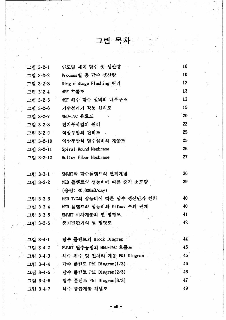
2% 3-2-1 Ag 3-2-2 2g 3-2-3 ZLg 312-4 ZLg 3-2-5 2% 3-2-6 ZLg 3-2-7
’ ZLg 3-2-8 2% 3-2-9 2% 3-2-10 2% 3-2-11 2g 3-2-12
119 3-3-1 2% 3-3-2
1% 3-3-3 29 3-3-4 2% 3-3-5 ZLg 3-3-6
2g 3-4-1 3% 3-4-2 2% 3-4-3 xi;! 3-4-4 2% 3-4-5
2% 3-4-7 2% 3-4-6
Q$*F34 @+W4 4%-s Spiral Wound Membrane
Hol 1 ow Fiber Membrane
@+ =@E4 Block Diagram SMART @+%%q MED-TVC E=€
- xii -
10 10 12 13 13 15 20 22 25 25 26 27
36 39
40 40
41 42
44 45 45 46 46
47 49

2% 3-4-8
2% 3-4-9
2% 3-4-10
2g 3-4-11
2% 3-4-12
2% 3-4-13
2g 3-4-14
2% 3-5-1
2% 3-5-2
2% 3-5-3
2% 3-6-1
2g 3-6-2
Z!.g 3-6-3
2% 3-6-4
2g 3-6-5
2% 3-6-6
g+ =@E ~lp]z @ 9+71 (Thermocompressor )
SMART %+7f]%q-$* Ejector A]&g .
Desuperheater Ins tal 1 at i on Di agram Steam Transformer PFD Seawater Discharge Control
Make-up Water Flow Control
54 .
55
57
58
60
64
68
83
86
89
103
103
104
105
106
106
- xiii -

1

2

3

I . . j
4


6

7

8

~~
I . i 1
I I
- d 53 (Freezing),
- cfe+2!4 (Multi-Stage Flashing),
- cfgZ-8-g (Multi-Effect Distillation),
- *F%?-g (Reverse Osmosis) 1 -
501 %cf. IDA(1nternational Desalination Association) 9 ex41 4 313 20003 41 A1 41
9

I
ProcessP # Ff3 @!@St (-2001 E)
8.06%
10

11

Vaoor
, , , , # , , I , , , , \ \ \ \ \ \ \ \ \ \ \ \ 11 I f 111111 11 \ \ \ \ \ \ \ \ \ \ \ \ + ,,,,,,,,,#,,
bndensate I
- Heated Seawater
- m - m - - b b b b O b O b b b 0
Distillate Condender
12

2% 3-2-4 MSF E%€
13

14

15

. .
16

7 Q
94
17

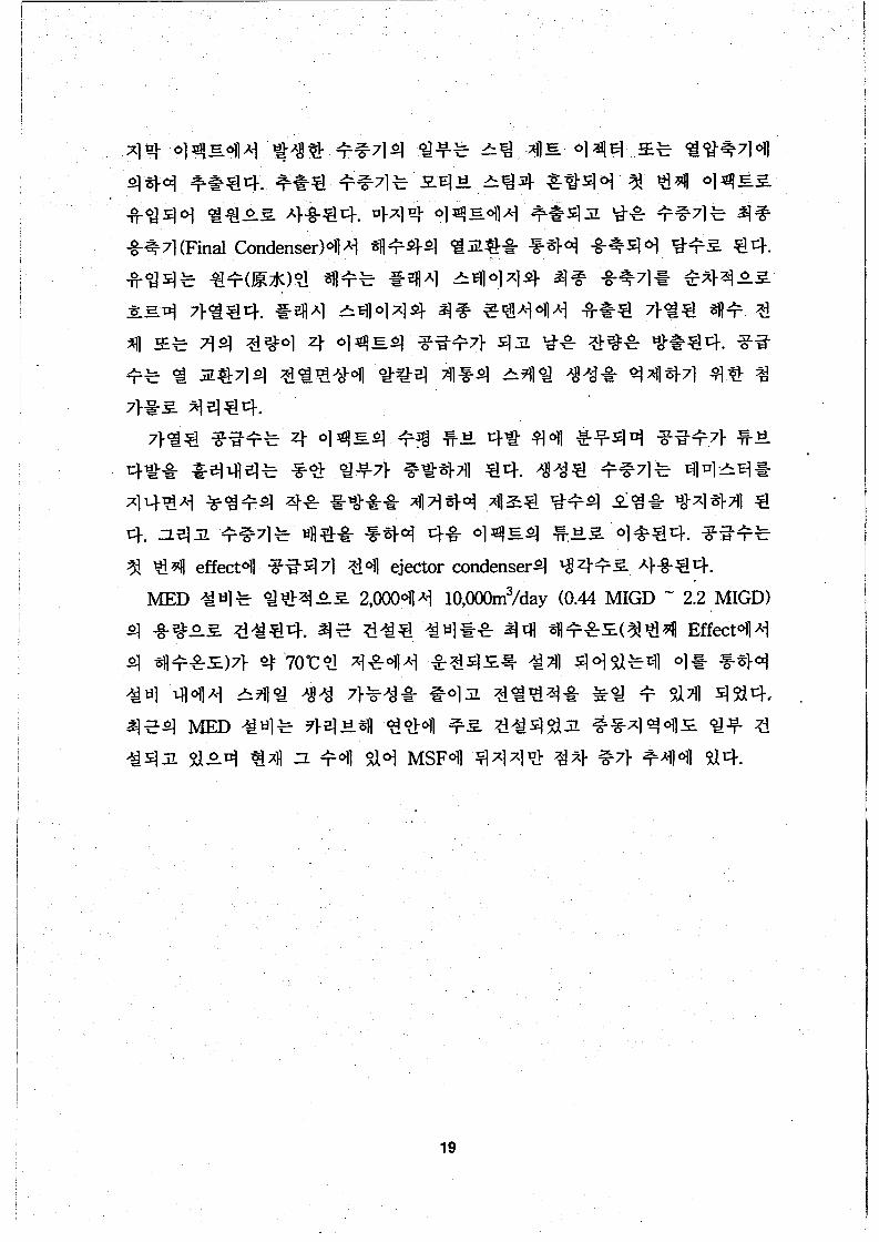
19

MED-TVC . (MULTI EFFECT DISTILLATION-THERMAL VAPOR COMPRESSION)
-- TYPICAL FLOW DIAGRAM
3% 3-2-7 MED-TVC -%ZS . .
20 '

q.’ @Fq (Membrane)%

Cathode I-)
Cation-Transfer Membrano
Demineralized Product
Concentrate
Anion-Ttansfe r Membrane
Cation-Transfer Membrane
_ " I I_ Anode (+)
22

23

(2) q 2% 8 71 Fq % (Electro-dialysis Reversal Process: EDR)
24


,
2 0
3% 3-2-11 Spiral Wound Membrane
26

I g 3-2-12 Hollow Fiber Membrane
27

28

eq -$+(Industrial water): %-$$(Potable water): TDS 1,OOO m g / l O 1 8 )
TDS lOmg/l 015)
29

30

(6) Ad %(Performance)
31

32 .

33

I B l 3 % $ I MSF I MED-TVC
Largest Plant (per unit) 56,820 m3/day 15,000 m3/day (12.5 mGD) (3.5MIGD)
Feed Water -TDS (ppm) r -Feed treatment -Chemical (mm) 2 ' 4 2 - 4
-TD^ ' , 1 - 2 5 nc - OK Product Water
Below 50,OOO Below 50,000 Anti-scale/foam Anti-scale/foam
90 - 112 deg C
8 - 20
'erformance -Max .operating temp. - P.R
70 deg C
8 - 20 3&M Characteristics - Operationa Attention - Maintenance Attention -Potential for scale
-Potential for corrosion formation
Relative advantages
I Large I- Mid to low -
Close, continual Minimal Medium Average to low Medium Low
Low to medium Low - High quality -High quality
product product - Long history of -Easy & Fast to
operation start-up & shut - Easv owration down
- - L" -&- I-? Principal applications
Relative disadvantages
W
Published
available Use high quality dah are materia,
capacity
available
water
capac1ry
- MP steam is .r seam is railable
ith power
RO 33,182 m3/day 35 MIGD)
Below 50,Ooo Zhloride,acid,polym !ST-
(500 35-50
NA . NA 10
Ambient
NA
High(pretreatment1 Medium Average
Very low
-Fairly simple to operate - Variety of sizes & modules (train)
-Membrane life
-Need extensive limit of 3-51 years
pre-treatment of feed water
34

35

MSF MED Power Back Back
Prime Turbine %me ' Turbine Steam Extraction
Pressure Pressure Steam Extraction
Turbine Turbine Only
330.0 330.0 330.0 330.0 330.0 330.0 330.0
100.0 80.0 87.0 59.0 85.0 93.0 87.0
Thermal . PowedMWt) Total Electric PowedMWe)
Water Production (rnWciav)
Net Electric Power(MWe)
0.0 40,000 40,000 140,000 40,000 40,000 77,OOO
100.0 75.0 82.0 44.0 83.0 90.0 83.0
n
f I I
36
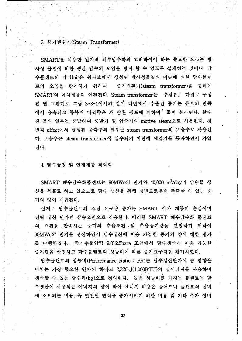
37

I
I
I I I ! 1
! ~
j
! i
,
1
I
I I !
38

h 300000 I I
275000 0,
C c 250000 s * 225000 2 200000 s 150000
8 100000
f 175000
E 125000 m
5 6 7 8 9 10 11 12 13 14 15 PR (kg12326kJ)
39


, .
j i i i ~
!
1
1 f I
41

i F m P w r Plant
9.0 bard @sat
2779.7 ILMQ 7.50 kglsec
After Steam Trsnsfamer 8.9 bra
174.9 C 740.6 kvkg 7.50 kglsec
Retum to Power Plant 8.8 bard
169.9 C 174.4 @sat c 710.7 ILMQ 7.50 Wsec
T o T h e r m ~ p e s s a 8.0 bara
2.767.5 kvkg 170.4 C &t+5
5.9 kgsec
~ ; 'v 4 FmCc$eeteRetum
. 69.1 C 289.9, kyke
5.9 Wsec
42

- %%!+ 4 w 3 65t - Ad% Bl (Performance ratio) 19.6 kg of distillate/2326 kJ
- 3 Qqi’] 3s $71 g€/%q 176W8.0 b a a - 1st effect4 G719q 0.25 bara
- Maximum Distillate Temperature 40.0 ‘c
- Brine Blowdown Temperature 41.0C
- Maximum Seawater Salinity 40,ooOppm
- 5x7;” AI-Br / Titanium(Top 3 row)
- Frequency of Acid Cleaning 127H % - %%%714 g71W %%I+ ”d-q 0.139 bara
43

Steam
r Pre-Treatment MED Desalination c
Potable Water
From Sea 1 I
I Condensate Brine (To Sea) BC
3% 3-4-1 %+%%!!E4 Block Diagram
44

. .
-I- 1 I ] _--
1
I------------ --1
45

I$ 3-4-4 P&I Diagram (1/3)
~ $ 3 - 4 - 5 %++!?@Eq P&I Diagram (2/3)
46

ZL$ 3-4-6 %+%?!E P&I Diagram (3/3)
47

48

49

50 .

fE 3-4-1 SMART %+*$$%!!E MED-TVCs;'E3q %!'?!AT!
Parameter Unit Value
Total Dissolved Solids Cooling Seawater Temperature
?- %I? - 2 5 w W
Cooling Water Temperatur
I kg/2326/kJ I 19.6
PPm 4woO
"c 33.0 "c 47.7
"c 9.0
Anti-scalent dosing
Scale Temperature Rise
51

X 3-4-2 OSWq X $ ~ T + A4 o +x Sodium 10.561 g/kg
Magnesium . 1.272 g/kg
Calcium 0.400 g/kg
Potassium 0.380 g/kg
Chloride 18.980 g/kg
Sulfate 2.649 g/kg
Hydrogen carbonate 0.142 g/kg
Bromine 0.065 g k g
Total 34.449 g/kg
52

Tubes for Effects - Top 3 rows - Other rows
Titanium Al-Brass
0.5t 0.7t
T u b e s for Fin* Titanium . 0.5t Condenser I Tubes for Preheater 1 . Titanium I 0.5t I
Tube plate SS 316L Tube support SS 316L
53

1 - - _ _ ~ . . . _ _ . . . _ . . . _ ..
I I 1 I J I . I s I s
Lf. $9 "d-%71(Thennal Vapor Compressor)
54

t2.j f If.l I S d o n
zz % 3-4-9 3 9% 71 (Thennocompressor)
55

- +.g+ t$J% g n lxlOo% Horizontal
-4 T 2- S l I i u- 2x100%. Horizontal .
- %++ g g 2x100% Horizontal

. .
2nd STAGE EJECTOR
1st STAGE EJECTOR
CONDENSER
’ TO 1 s t EFFECT A CONDENSER
57

pi. Desuperheater
3 4 3-4-11 Desuperheater Installation Diagram
H). 3lq41 ?%la1 %(Chemical Dosing System)
58

59


61

62

TAH
1 ii3 3-4- 13 Seawater Discharge Control
64

65

i
!
I I i i ~
i i
! j
. .
q. 94s 4 -$- 3-8 (Fail-safe Requirements)


!
F] 8 2 4 3 C +. I %
a 8242C
0 8241C
. I
h
3% 3-4-14 Make-up Water Flow Control
w!
68 I

415%. '$I-941% CHEMISTRY DESIGN GUIDE
69

70

71

. .
72

C02 + H20 = (CH20) + 6H20
73

74

(S04)Z- +8e- + 8H+ = S2- + 4H20
75

76

77

78

79

,
7f. 7H.3.
80

81

- -

Deaerator
Brine Heater Heat Recovery
I
I I I - I
I I L _ _ _ _ _ 0 _ _ _ _ _ _ _ J
S onge ball CPeaning loop
Collector/ Pump
83

84

as

0 20 40 60 80 100 120 140 160 180 200
E€ (OC)

I
, 1
87

(HC03)- + H+ = H20 + C02 (CO3)Z- + H+ = H20 + C02

89

(HCO-)3 + Ca(OH)2 = CaC03 + H20 + (OH)-
C02 + Ca(OHl2 = CaC03 + H20 (C0212 + Ca(OH12 = CaC03 + 2(OH)-
Mg2+ + Ca(OH12 = Mg(OH)2 + Ca2+
Ca2+ + Na2C03 = CaCO3 + 2Na+
90

A. 33$!l (Phosphate) q % 7). .
B. 3 41 01 E41 (Chelate agent) E2 4 4 41 (Sequestering agent)q % 7).
91

92

93

94

95

96

97

98

. .
99

. .
71$1(Brackish water) RO =%E
100

71-
101

102

m n I al L 3 u) u)
E n
2 0 6 2 0
16 6 0 0 Y
e 1 2 5 8 0 3
m 0) P
8 5 6 0 E al
'I-
L
4 -+- -Pr imary S G inlet t e m p . 5 4 0 - - 0 - - P r i m a r y S G out let t e m p .
0 5 2 0 0 5 0 100 150 ' 2 0 0 2 5 0 3 0 0
T i m e , s e c
3% 3-6-2 E j $ 3 A 1 A ) X A 1 q $$q 2 $E %g
103

3.0
2.5
er m 2.0 z 0
1.5
1 .o 0 5 10 15
Time (I)
DNBR
ZLg 3-6-3
104 .

x,
600 j 8
580 16
560
14
540
12 520
500 10 0 20 60 80 100
40 Tlmr(r)
Primary Coolant Temperature and Pressure
105

6
0
Time (s) 0 10 D
620 19
18
600 17
580 16
15
14
540 13 2o
Time@) 0 10 30 40 50
Primary temperature and pressure
ZLq 3-6-6 S+@ * @ A \ X A ] q %q ‘3! P-€ @%
C
2
106

107

108

109

I
G137-DS-D300M) KAERI/CM-* **/200 1
110 '

BIBLIOGRAPHIC INFORMATION SHEET -~ ~ ~
Performing Org. ' Sponsoring 0%. Report No. Report No.
Stamdard Report No. INIS Subject Code
1 I KAERI/CM-***/2001 G137-DS-D300-00
Changwori Publisher Publication Place
Development of Basic Model for Seawater Desalination System Subtitle
Hong, Soon-Gil/ Senior Vice Resident Desal. Manufacturing and Desigr
Kum-Su Park, In-Sup Song , Jong-Sung Lim, Jong Myong Hong, Byung
3 Project Manager and Department Engineering Researcher and .
Publication Date
DOOSAN 2002.04
Page p. III. & Tab.
Note . I
Size Cm. Yes@), No ( 1
Open(O),. Restricted( 1, Classified - Class Document 1 DOOSAN Performing Organization
Technical Development Report Type
Contract No.
Abstract (15-20 Lines)
The production capacity of the SMART nuclear desalination plant is 40,000 m3 per day. In this report the design concept of the desalination plant for SMART nuclear power plant has been identified and factors which will effect on the performance and cost have been optimized. The SMART desalination dant consists of four (4) MED-TVC(Mu1ti Effect Distillation with Thermal Vapor Compression1 fistillers and the capacity of each distiller is 10,ooOm3 per day. In view of the best utilization of the 2xtracted steam from the steam turbine,. the MED-TVC distiller has been selected as a desalinatior mess. In order to preclude any pollutant transfer from the nuclear power plant, a steam transformei ?as been considered as an isolating mean. The steam transformer generates and provide the heating Stem from the extracted steam. The heating steam is supplied to the thermo compressor of the MEC lesalination plant. The selected desalination process utilizes a thermo compressor to enhance the steam xonomy of the whole power and water plant. The horizontal tube falling film type evaporator has xen selected as the main equipment of the SMART desalination plant. The design life time of the iesalination plant is 30 years, the minimum performance ratio is 19.6 kg of distillate per 2,326 kJ ol jtem consumption. The design interval of the two successive acid cleaning is 12 months. The tor d n e temperature (T.B.T) is 65oC and the design ambient seawater temperature is 33oC. One of the nost important factors in determining the water production cost is the performance ratio. The selected xxformance ration is based on the sensitivity analysis. Also, transient effect due to the interactior xtween the SMART nuclear plant and desalination plant has been assessed. According to the results )f the transient analysis, the transient effects are bounded with the SAFDL and it seems not to have serious negative effects on the safetv
I
.
Seawater Desalination Plant, SMART, MED-TVC, Steam Transformer, I Subject Keywords (About 10 words)
Thermocompressor, Performance Ratio, Basic Design
111
Related Documents