DEVELOPMENT OF AN OPEN PATH LASER IGNITION SYSTEM FOR A LARGE BORE NATURAL GAS ENGINE: PART 1 SYSTEM DESIGN David L. Ahrens, Azer P. Yalin, Daniel B. Olsen, and Gi-Heon Kim Colorado State University Department of Mechanical Engineering Fort Collins, Colorado, 80523, USA ABSTRACT Using a laser, as opposed to a conventional (electrical) spark plug, to create a combustion initiating spark is potentially advantageous for several reasons: flexibility in choosing and optimizing the spark location, in particular to move the spark away from solid heat sinks; production of a more robust spark containing more energy; and obviation of electrode erosion problems. These advantages may lead to an extension of the lean limit, an increase in engine thermal efficiency, and the concomitant benefits of reduced pollutant emissions. This paper presents the design of a laser ignition system appropriate for a large bore natural gas engine. Design considerations include: optimization of spark location, design of beam delivery system and optical plug, and mitigation of vibration and thermal effects. Engine test results will be presented in the second paper of this two-paper series. Keywords: laser ignition, gas engine, computational fluid dynamic modeling, flame propagation, vibration, laser beam energy INTRODUCTION In 1978 J.D. Dale 1 first demonstrated laser ignition for combustion initiation of internal combustion engines. The basic concept of laser ignition is to use a laser beam (as opposed to a conventional electrical spark plug) to produce a combustion initiating spark. By focusing the beam from a pulsed laser to a sufficiently high intensity (small beam dimension) a combustion initiating spark may be produced. Since the initial demonstrations by Dale et al, subsequent investigations 2,3 have demonstrated the potential benefits of laser ignition when applied to engines. These potential benefits may include improvements in emissions, horse power, fuel consumption, and extension of the lean limit. Our research will investigate how these benefits apply to a high power gas engine, which would also benefit from extended maintenance intervals with a laser system since electrode erosion is no longer a limitation. In this work design details of a laser based ignition system for a Cooper-Bessemer GMV-4TF two-stroke cycle, large bore natural gas engine are presented. In particular, this paper focuses on laser selection (type and frequency), the effect of vibrations and heat loading on the laser, optimization of spark location, beam delivery and focusing, and system design challenges associated with window mounting. In contrast to most past research in which the laser is located remotely from the engine, we elect to mount the laser directly on the engine. This configuration is believed to be advantageous since optical path lengths (and misalignment possibilities) are reduced and fewer components are required. Optimization of spark location is addressed through the use of computational fluid dynamic (CFD) modeling which shows that the optimal location for fastest flame propagation and most complete burn is slightly off the cylinder center-axis. This implementation is based on the use of a pulsed (Q-switched) neodymium yttrium-aluminum- garnet (Nd:YAG) laser operating in its fundamental mode at 1064 nm. Discussed are design considerations for beam access via two different ports: the air start port and the primary spark plug port. Two laser spark locations are examined for each port. Through the air start port the spark can be placed at the anticipated optimal spark location as well as in the center of the combustion chamber. Using the spark plug port the spark can be located at the same location as the electrical spark as well as several cm away from the wall. These locations allow a direct comparison of the combustion performance of optical and conventional sparks and a study of the effect of moving 1 Copyright © 2005 by ASME Proceedings of ICES2005 ASME Internal Combustion Engine Division 2005 Spring Technical Conference April 5-7, 2005, Chicago, IL, USA ICES2005-1060 Downloaded From: https://proceedings.asmedigitalcollection.asme.org on 06/30/2019 Terms of Use: http://www.asme.org/about-asme/terms-of-use

Welcome message from author
This document is posted to help you gain knowledge. Please leave a comment to let me know what you think about it! Share it to your friends and learn new things together.
Transcript
Downloaded Fr
DRAFT Proceedings of ICES2005
ASME Internal Combustion Engine Division 2005 Spring Technical ConferenceApril 5-7, 2005, Chicago, IL, USA
ICES2005-1060
DEVELOPMENT OF AN OPEN PATH LASER IGNITION SYSTEM FOR A LARGE BORE NATURAL GAS ENGINE: PART 1 SYSTEM DESIGN
David L. Ahrens, Azer P. Yalin, Daniel B. Olsen, and Gi-Heon Kim
Colorado State University Department of Mechanical Engineering
Fort Collins, Colorado, 80523, USA
Proceedings of ICES2005 ASME Internal Combustion Engine Division 2005 Spring Technical Conference
April 5-7, 2005, Chicago, IL, USA
ICES2005-1060
ABSTRACT Using a laser, as opposed to a conventional (electrical) spark plug, to create a combustion initiating spark is potentially advantageous for several reasons: flexibility in choosing and optimizing the spark location, in particular to move the spark away from solid heat sinks; production of a more robust spark containing more energy; and obviation of electrode erosion problems. These advantages may lead to an extension of the lean limit, an increase in engine thermal efficiency, and the concomitant benefits of reduced pollutant emissions. This paper presents the design of a laser ignition system appropriate for a large bore natural gas engine. Design considerations include: optimization of spark location, design of beam delivery system and optical plug, and mitigation of vibration and thermal effects. Engine test results will be presented in the second paper of this two-paper series. Keywords: laser ignition, gas engine, computational fluid dynamic modeling, flame propagation, vibration, laser beam energy INTRODUCTION In 1978 J.D. Dale1 first demonstrated laser ignition for combustion initiation of internal combustion engines. The basic concept of laser ignition is to use a laser beam (as opposed to a conventional electrical spark plug) to produce a combustion initiating spark. By focusing the beam from a pulsed laser to a sufficiently high intensity (small beam dimension) a combustion initiating spark may be produced. Since the initial demonstrations by Dale et al, subsequent investigations2,3 have demonstrated the potential benefits of laser ignition when applied to engines. These potential benefits may include improvements in emissions, horse power, fuelom: https://proceedings.asmedigitalcollection.asme.org on 06/30/2019 Terms of Use:
consumption, and extension of the lean limit. Our research will investigate how these benefits apply to a high power gas engine, which would also benefit from extended maintenance intervals with a laser system since electrode erosion is no longer a limitation. In this work design details of a laser based ignition system for a Cooper-Bessemer GMV-4TF two-stroke cycle, large bore natural gas engine are presented. In particular, this paper focuses on laser selection (type and frequency), the effect of vibrations and heat loading on the laser, optimization of spark location, beam delivery and focusing, and system design challenges associated with window mounting. In contrast to most past research in which the laser is located remotely from the engine, we elect to mount the laser directly on the engine. This configuration is believed to be advantageous since optical path lengths (and misalignment possibilities) are reduced and fewer components are required. Optimization of spark location is addressed through the use of computational fluid dynamic (CFD) modeling which shows that the optimal location for fastest flame propagation and most complete burn is slightly off the cylinder center-axis. This implementation is based on the use of a pulsed (Q-switched) neodymium yttrium-aluminum-garnet (Nd:YAG) laser operating in its fundamental mode at 1064 nm. Discussed are design considerations for beam access via two different ports: the air start port and the primary spark plug port. Two laser spark locations are examined for each port. Through the air start port the spark can be placed at the anticipated optimal spark location as well as in the center of the combustion chamber. Using the spark plug port the spark can be located at the same location as the electrical spark as well as several cm away from the wall. These locations allow a direct comparison of the combustion performance of optical and conventional sparks and a study of the effect of moving
1 Copyright © 2005 by ASME
http://www.asme.org/about-asme/terms-of-use
Downlo
(optimizing) the laser spark location. Engine test results will be presented in the second paper of this two-paper series.
COOPER-BESSEMER GMV-4TF ENGINE
The engine used in these studies is a Cooper-Bessemer GMV-4TF two-stroke cycle, large bore natural gas engine with a 36 cm bore and stroke. Nominal operating conditions are 330 kW, 300 rpm, and intake air manifold pressure 25.4 kPag. It operates with mechanically actuated direct fuel injection. The engine burns a lean fuel and air mixture with a trapped equivalence ratio of approximately 0.8. More details on the test engine can be found in other work4, ,5 6.
COMPUTATIONAL FLUID DYNAMIC MODELING
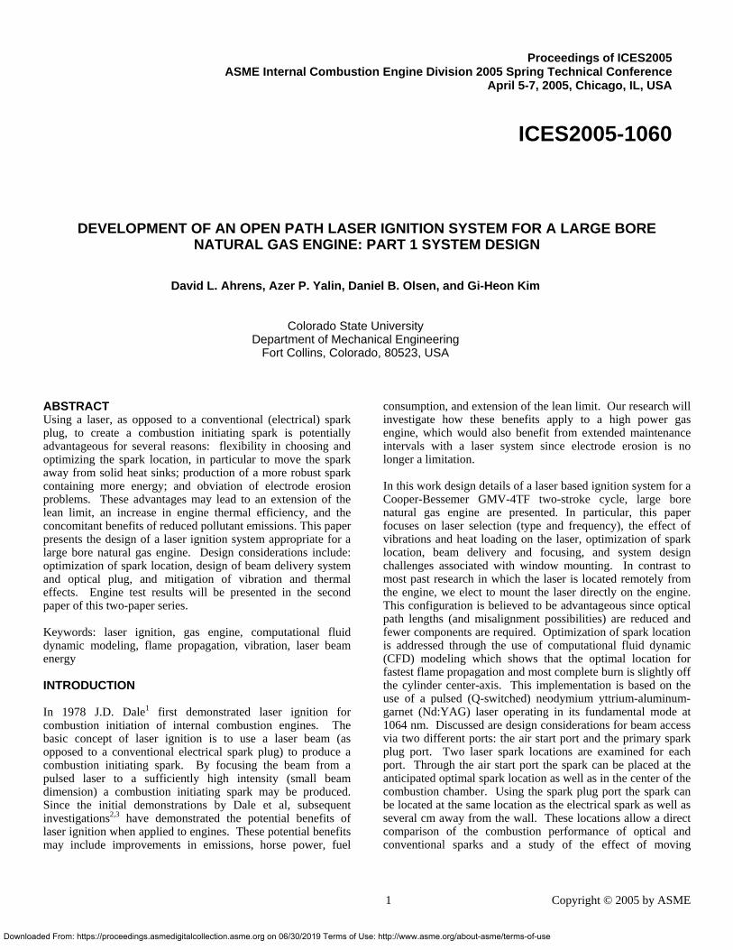
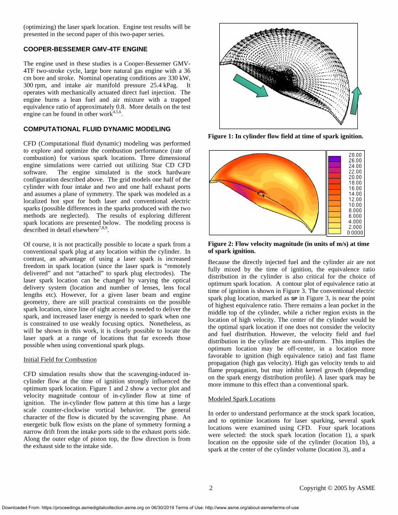
CFD (Computational fluid dynamic) modeling was performed to explore and optimize the combustion performance (rate of combustion) for various spark locations. Three dimensional engine simulations were carried out utilizing Star CD CFD software. The engine simulated is the stock hardware configuration described above. The grid models one half of the cylinder with four intake and two and one half exhaust ports and assumes a plane of symmetry. The spark was modeled as a localized hot spot for both laser and conventional electric sparks (possible differences in the sparks produced with the two methods are neglected). The results of exploring different spark locations are presented below. The modeling process is described in detail elsewhere7, ,8 9. Of course, it is not practically possible to locate a spark from a conventional spark plug at any location within the cylinder. In contrast, an advantage of using a laser spark is increased freedom in spark location (since the laser spark is “remotely delivered” and not “attached” to spark plug electrodes). The laser spark location can be changed by varying the optical delivery system (location and number of lenses, lens focal lengths etc). However, for a given laser beam and engine geometry, there are still practical constraints on the possible spark location, since line of sight access is needed to deliver the spark, and increased laser energy is needed to spark when one is constrained to use weakly focusing optics. Nonetheless, as will be shown in this work, it is clearly possible to locate the laser spark at a range of locations that far exceeds those possible when using conventional spark plugs. Initial Field for Combustion CFD simulation results show that the scavenging-induced in-cylinder flow at the time of ignition strongly influenced the optimum spark location. Figure 1 and 2 show a vector plot and velocity magnitude contour of in-cylinder flow at time of ignition. The in-cylinder flow pattern at this time has a large scale counter-clockwise vortical behavior. The general character of the flow is dictated by the scavenging phase. An energetic bulk flow exists on the plane of symmetry forming a narrow drift from the intake ports side to the exhaust ports side. Along the outer edge of piston top, the flow direction is from the exhaust side to the intake side.
aded From: https://proceedings.asmedigitalcollection.asme.org on 06/30/2019 Terms of Use
Figure 1: In cylinder flow field at time of spark ignition.
Figure 2: Flow velocity magnitude (in units of m/s) at time of spark ignition.
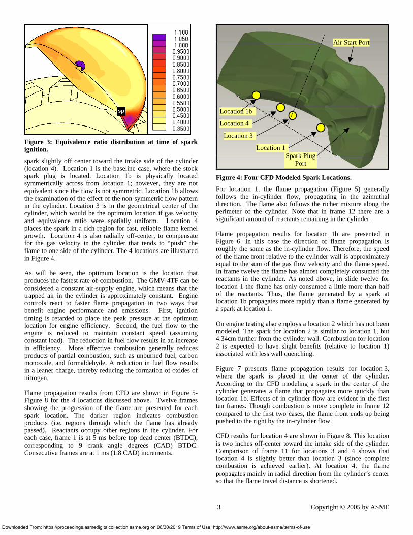
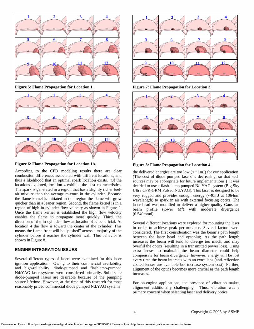
Because the directly injected fuel and the cylinder air are not fully mixed by the time of ignition, the equivalence ratio distribution in the cylinder is also critical for the choice of optimum spark location. A contour plot of equivalence ratio at time of ignition is shown in Figure 3. The conventional electric spark plug location, marked as SP in Figure 3, is near the point of highest equivalence ratio. There remains a lean pocket in the middle top of the cylinder, while a richer region exists in the location of high velocity. The center of the cylinder would be the optimal spark location if one does not consider the velocity and fuel distribution. However, the velocity field and fuel distribution in the cylinder are non-uniform. This implies the optimum location may be off-center, in a location more favorable to ignition (high equivalence ratio) and fast flame propagation (high gas velocity). High gas velocity tends to aid flame propagation, but may inhibit kernel growth (depending on the spark energy distribution profile). A laser spark may be more immune to this effect than a conventional spark. Modeled Spark Locations In order to understand performance at the stock spark location, and to optimize locations for laser sparking, several spark locations were examined using CFD. Four spark locations were selected: the stock spark location (location 1), a spark location on the opposite side of the cylinder (location 1b), a spark at the center of the cylinder volume (location 3), and a
2 Copyright © 2005 by ASME
: http://www.asme.org/about-asme/terms-of-use
Downlo
Figure 3: Equivalence ratio distribution at time of spark ignition.
spark slightly off center toward the intake side of the cylinder (location 4). Location 1 is the baseline case, where the stock spark plug is located. Location 1b is physically located symmetrically across from location 1; however, they are not equivalent since the flow is not symmetric. Location 1b allows the examination of the effect of the non-symmetric flow pattern in the cylinder. Location 3 is in the geometrical center of the cylinder, which would be the optimum location if gas velocity and equivalence ratio were spatially uniform. Location 4 places the spark in a rich region for fast, reliable flame kernel growth. Location 4 is also radially off-center, to compensate for the gas velocity in the cylinder that tends to “push” the flame to one side of the cylinder. The 4 locations are illustrated in Figure 4. As will be seen, the optimum location is the location that produces the fastest rate-of-combustion. The GMV-4TF can be considered a constant air-supply engine, which means that the trapped air in the cylinder is approximately constant. Engine controls react to faster flame propagation in two ways that benefit engine performance and emissions. First, ignition timing is retarded to place the peak pressure at the optimum location for engine efficiency. Second, the fuel flow to the engine is reduced to maintain constant speed (assuming constant load). The reduction in fuel flow results in an increase in efficiency. More effective combustion generally reduces products of partial combustion, such as unburned fuel, carbon monoxide, and formaldehyde. A reduction in fuel flow results in a leaner charge, thereby reducing the formation of oxides of nitrogen. Flame propagation results from CFD are shown in Figure 5-Figure 8 for the 4 locations discussed above. Twelve frames showing the progression of the flame are presented for each spark location. The darker region indicates combustion products (i.e. regions through which the flame has already passed). Reactants occupy other regions in the cylinder. For each case, frame 1 is at 5 ms before top dead center (BTDC), corresponding to 9 crank angle degrees (CAD) BTDC. Consecutive frames are at 1 ms (1.8 CAD) increments.
sp
aded From: https://proceedings.asmedigitalcollection.asme.org on 06/30/2019 Terms of Use
Figure 4: Four CFD Modeled Spark Locations.
For location 1, the flame propagation (Figure 5) generally follows the in-cylinder flow, propagating in the azimuthal direction. The flame also follows the richer mixture along the perimeter of the cylinder. Note that in frame 12 there are a significant amount of reactants remaining in the cylinder. Flame propagation results for location 1b are presented in Figure 6. In this case the direction of flame propagation is roughly the same as the in-cylinder flow. Therefore, the speed of the flame front relative to the cylinder wall is approximately equal to the sum of the gas flow velocity and the flame speed. In frame twelve the flame has almost completely consumed the reactants in the cylinder. As noted above, in slide twelve for location 1 the flame has only consumed a little more than half of the reactants. Thus, the flame generated by a spark at location 1b propagates more rapidly than a flame generated by a spark at location 1. On engine testing also employs a location 2 which has not been modeled. The spark for location 2 is similar to location 1, but 4.34cm further from the cylinder wall. Combustion for location 2 is expected to have slight benefits (relative to location 1) associated with less wall quenching. Figure 7 presents flame propagation results for location 3, where the spark is placed in the center of the cylinder. According to the CFD modeling a spark in the center of the cylinder generates a flame that propagates more quickly than location 1b. Effects of in cylinder flow are evident in the first ten frames. Though combustion is more complete in frame 12 compared to the first two cases, the flame front ends up being pushed to the right by the in-cylinder flow. CFD results for location 4 are shown in Figure 8. This location is two inches off-center toward the intake side of the cylinder. Comparison of frame 11 for locations 3 and 4 shows that location 4 is slightly better than location 3 (since complete combustion is achieved earlier). At location 4, the flame propagates mainly in radial direction from the cylinder’s center so that the flame travel distance is shortened.
Air Start Port
Location 1b
Location 4
Location 3
Location 1 Spark Plug
Port
3 Copyright © 2005 by ASME
: http://www.asme.org/about-asme/terms-of-use
Down
Figure 5: Flame Propagation for Location 1.
Figure 6: Flame Propagation for Location 1b.
According to the CFD modeling results there are clear combustion differences associated with different locations, and thus a likelihood that an optimal spark location exists. Of the locations explored, location 4 exhibits the best characteristics. The spark is generated in a region that has a slightly richer fuel-air mixture than the average mixture in the cylinder. Because the flame kernel is initiated in this region the flame will grow quicker than in a leaner region. Second, the flame kernel is in a region of high in-cylinder flow velocity as shown in Figure 2. Once the flame kernel is established the high flow velocity enables the flame to propagate more quickly. Third, the direction of the in cylinder flow at location 4 is beneficial. At location 4 the flow is toward the center of the cylinder. This means the flame front will be “pushed” across a majority of the cylinder before it reaches the cylinder wall. This behavior is shown in Figure 8.
ENGINE INTEGRATION ISSUES Several different types of lasers were examined for this laser ignition application. Owing to their commercial availability and high-reliability, diode-pumped and flashlamp-pumped Nd:YAG laser systems were considered primarily. Solid-state diode-pumped lasers are desirable because of the pumping source lifetime. However, at the time of this research for most reasonably priced commercial diode pumped Nd:YAG systems
11 12
41 2 3
5 6 7 8
9 10
41 2 3
6 7 8 5
9 10 11 12
loaded From: https://proceedings.asmedigitalcollection.asme.org on 06/30/2019 Terms of Use:
Figure 7: Flame Propagation for Location 3.
Figure 8: Flame Propagation for Location 4.
the delivered energies are too low (<~ 1mJ) for our application. (The cost of diode pumped lasers is decreasing, so that such sources may be appropriate for future implementations.) It was decided to use a flash- lamp pumped Nd:YAG system (Big Sky Ultra CFR-GRM Pulsed Nd:YAG). This laser is designed to be very rugged and provides enough energy (∼40mJ at 1064nm wavelength) to spark in air with external focusing optics. The laser head was modified to deliver a higher quality Gaussian beam profile (lower M2) with moderate divergence (0.540mrad). Several different locations were explored for mounting the laser in order to achieve peak performance. Several factors were considered. The first consideration was the beam’s path length between the laser head and optoplug. As the path length increases the beam will tend to diverge too much, and may overfill the optics (resulting in a transmitted power loss). Using extra lenses to maintain the beam diameter could help compensate for beam divergence; however, energy will be lost every time the beam interacts with an extra lens (anti-reflection coated lenses are available but increase system cost). Further, alignment of the optics becomes more crucial as the path length increases. For on-engine applications, the presence of vibration makes alignment additionally challenging. Thus, vibration was a primary concern when selecting laser and delivery optics
1 2 4 3
5 6 7 8
9 10 11 12
4 3 1 2
5 7 8 6
9 10 1211
4 Copyright © 2005 by ASME
http://www.asme.org/about-asme/terms-of-use
Down
Modes of operation for test cylinder Mode # Start up Run
1 Spark plug Spark plug 2 Spark plug Spark plug & Laser 3 Spark plug Laser 4 Laser Laser
Table 1: Modes of operation.
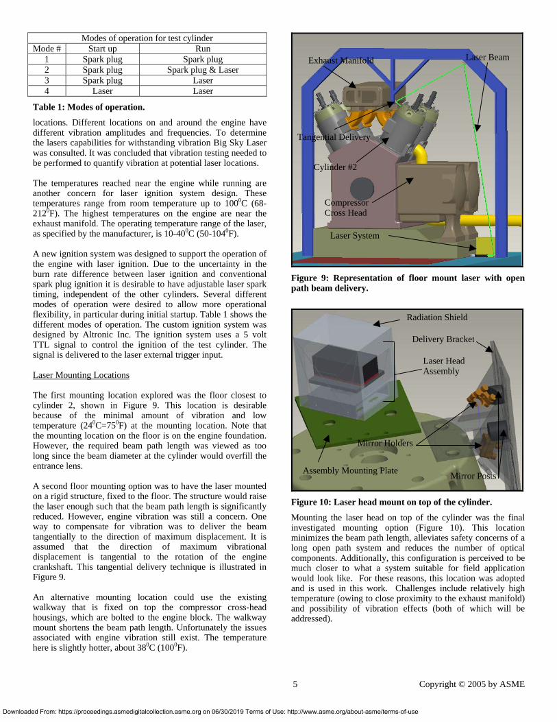
locations. Different locations on and around the engine have different vibration amplitudes and frequencies. To determine the lasers capabilities for withstanding vibration Big Sky Laser was consulted. It was concluded that vibration testing needed to be performed to quantify vibration at potential laser locations. The temperatures reached near the engine while running are another concern for laser ignition system design. These temperatures range from room temperature up to 1000C (68-2120F). The highest temperatures on the engine are near the exhaust manifold. The operating temperature range of the laser, as specified by the manufacturer, is 10-400C (50-1040F). A new ignition system was designed to support the operation of the engine with laser ignition. Due to the uncertainty in the burn rate difference between laser ignition and conventional spark plug ignition it is desirable to have adjustable laser spark timing, independent of the other cylinders. Several different modes of operation were desired to allow more operational flexibility, in particular during initial startup. Table 1 shows the different modes of operation. The custom ignition system was designed by Altronic Inc. The ignition system uses a 5 volt TTL signal to control the ignition of the test cylinder. The signal is delivered to the laser external trigger input. Laser Mounting Locations The first mounting location explored was the floor closest to cylinder 2, shown in Figure 9. This location is desirable because of the minimal amount of vibration and low temperature (240C=750F) at the mounting location. Note that the mounting location on the floor is on the engine foundation. However, the required beam path length was viewed as too long since the beam diameter at the cylinder would overfill the entrance lens. A second floor mounting option was to have the laser mounted on a rigid structure, fixed to the floor. The structure would raise the laser enough such that the beam path length is significantly reduced. However, engine vibration was still a concern. One way to compensate for vibration was to deliver the beam tangentially to the direction of maximum displacement. It is assumed that the direction of maximum vibrational displacement is tangential to the rotation of the engine crankshaft. This tangential delivery technique is illustrated in Figure 9. An alternative mounting location could use the existing walkway that is fixed on top the compressor cross-head housings, which are bolted to the engine block. The walkway mount shortens the beam path length. Unfortunately the issues associated with engine vibration still exist. The temperature here is slightly hotter, about 380C (1000F).
loaded From: https://proceedings.asmedigitalcollection.asme.org on 06/30/2019 Terms of Use
Figure 9: Representation of floor mount laser with open path beam delivery.
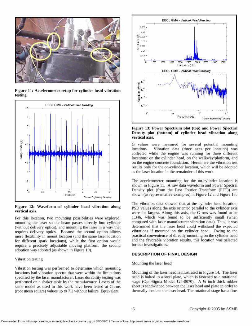
Figure 10: Laser head mount on top of the cylinder.
Mounting the laser head on top of the cylinder was the final investigated mounting option (Figure 10). This location minimizes the beam path length, alleviates safety concerns of a long open path system and reduces the number of optical components. Additionally, this configuration is perceived to be much closer to what a system suitable for field application would look like. For these reasons, this location was adopted and is used in this work. Challenges include relatively high temperature (owing to close proximity to the exhaust manifold) and possibility of vibration effects (both of which will be addressed).
Laser System
Laser BeamExhaust Manifold
Tangential Delivery
Cylinder #2
CompressorCross Head
Radiation Shield
Delivery Bracket
Laser Head Assembly
Mirror Holders
Assembly Mounting Plate Mirror Posts
5 Copyright © 2005 by ASME
: http://www.asme.org/about-asme/terms-of-use
Downlo
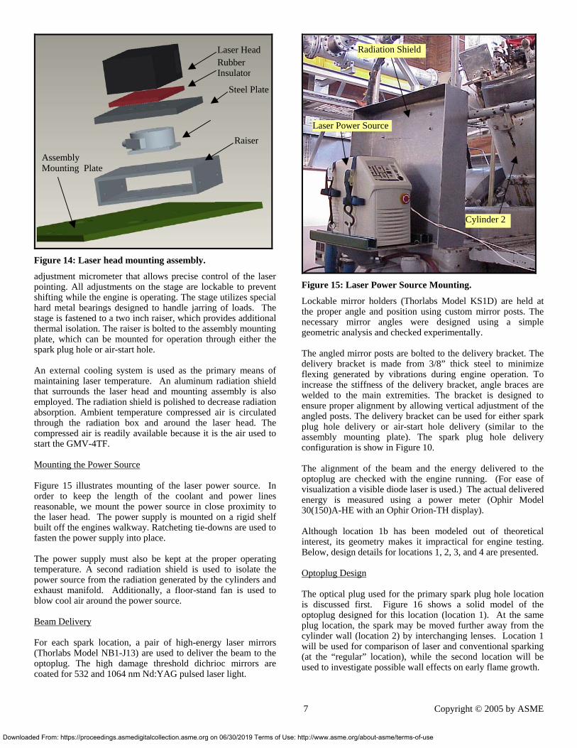
Figure 11: Accelerometer setup for cylinder head vibration testing.
Am
plitu
de (g
)
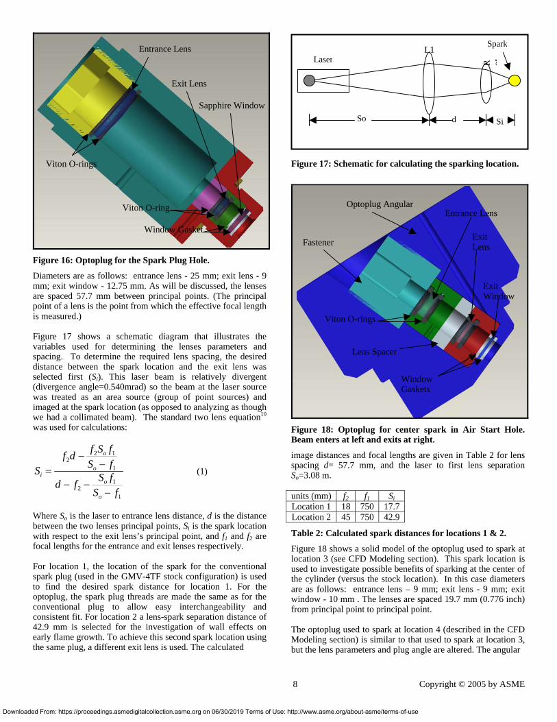
Figure 12: Waveform of cylinder head vibration along vertical axis.
For this location, two mounting possibilities were explored: mounting the laser so the beam passes directly into cylinder (without delivery optics), and mounting the laser in a way that requires delivery optics. Because the second option allows more flexibility in mount location (and the same laser location for different spark locations), while the first option would require a precisely adjustable moving platform, the second adoption was adopted (as shown in Figure 10). Vibration testing Vibration testing was performed to determine which mounting locations had vibration spectra that were within the limitations specified by the laser manufacturer. Laser durability testing was performed on a shaker table by the manufacturer. Lasers of the same model as used in this work have been tested at G rms (root mean square) values up to 7.1 without failure. Equivalent
aded From: https://proceedings.asmedigitalcollection.asme.org on 06/30/2019 Terms of Use:
Figure 13: Power Spectrum plot (top) and Power Spectral Density plot (bottom) of cylinder head vibration along vertical axis.
G values were measured for several potential mounting locations. Vibration data (three axes per location) was collected while the engine was running for three different locations: on the cylinder head, on the walkway/platform, and on the engine concrete foundation. Herein are the vibration test results only for the on-cylinder location, which will be adopted as the laser location in the remainder of this work. The accelerometer mounting for the on-cylinder location is shown in Figure 11. A raw data waveform and Power Spectral Density plot (from the Fast Fourier Transform (FFT)) are shown (as representative examples) in Figure 12 and Figure 13. The vibration data showed that at the cylinder head location, PSD values along the axis oriented parallel to the cylinder axis were the largest. Along this axis, the G rms was found to be 1.346, which was found to be sufficiently small (when compared with laser manufacturer vibration data). Thus, it was determined that the laser head could withstand the expected vibrations if mounted on the cylinder head. Owing to the practical convenience of directly mounting on the cylinder head and the favorable vibration results, this location was selected for our investigations.
DESCRIPTION OF FINAL DESIGN
Mounting the laser head Mounting of the laser head is illustrated in Figure 14. The laser head is bolted to a steel plate, which is fastened to a rotational stage (OptoSigma Model 124-0070). A ¼ inch thick rubber sheet is sandwiched between the laser head and plate in order to thermally insulate the laser head. The rotational stage has a fine
6 Copyright © 2005 by ASME
http://www.asme.org/about-asme/terms-of-use
Downlo
Figure 14: Laser head mounting assembly.
adjustment micrometer that allows precise control of the laser pointing. All adjustments on the stage are lockable to prevent shifting while the engine is operating. The stage utilizes special hard metal bearings designed to handle jarring of loads. The stage is fastened to a two inch raiser, which provides additional thermal isolation. The raiser is bolted to the assembly mounting plate, which can be mounted for operation through either the spark plug hole or air-start hole. An external cooling system is used as the primary means of maintaining laser temperature. An aluminum radiation shield that surrounds the laser head and mounting assembly is also employed. The radiation shield is polished to decrease radiation absorption. Ambient temperature compressed air is circulated through the radiation box and around the laser head. The compressed air is readily available because it is the air used to start the GMV-4TF. Mounting the Power Source Figure 15 illustrates mounting of the laser power source. In order to keep the length of the coolant and power lines reasonable, we mount the power source in close proximity to the laser head. The power supply is mounted on a rigid shelf built off the engines walkway. Ratcheting tie-downs are used to fasten the power supply into place. The power supply must also be kept at the proper operating temperature. A second radiation shield is used to isolate the power source from the radiation generated by the cylinders and exhaust manifold. Additionally, a floor-stand fan is used to blow cool air around the power source. Beam Delivery For each spark location, a pair of high-energy laser mirrors (Thorlabs Model NB1-J13) are used to deliver the beam to the optoplug. The high damage threshold dichrioc mirrors are coated for 532 and 1064 nm Nd:YAG pulsed laser light.
Laser HeadRubber Insulator
Steel Plate
Raiser
Assembly Mounting Plate
aded From: https://proceedings.asmedigitalcollection.asme.org on 06/30/2019 Terms of Use
Figure 15: Laser Power Source Mounting.
Lockable mirror holders (Thorlabs Model KS1D) are held at the proper angle and position using custom mirror posts. The necessary mirror angles were designed using a simple geometric analysis and checked experimentally. The angled mirror posts are bolted to the delivery bracket. The delivery bracket is made from 3/8” thick steel to minimize flexing generated by vibrations during engine operation. To increase the stiffness of the delivery bracket, angle braces are welded to the main extremities. The bracket is designed to ensure proper alignment by allowing vertical adjustment of the angled posts. The delivery bracket can be used for either spark plug hole delivery or air-start hole delivery (similar to the assembly mounting plate). The spark plug hole delivery configuration is show in Figure 10. The alignment of the beam and the energy delivered to the optoplug are checked with the engine running. (For ease of visualization a visible diode laser is used.) The actual delivered energy is measured using a power meter (Ophir Model 30(150)A-HE with an Ophir Orion-TH display). Although location 1b has been modeled out of theoretical interest, its geometry makes it impractical for engine testing. Below, design details for locations 1, 2, 3, and 4 are presented. Optoplug Design The optical plug used for the primary spark plug hole location is discussed first. Figure 16 shows a solid model of the optoplug designed for this location (location 1). At the same plug location, the spark may be moved further away from the cylinder wall (location 2) by interchanging lenses. Location 1 will be used for comparison of laser and conventional sparking (at the “regular” location), while the second location will be used to investigate possible wall effects on early flame growth.
Laser Power Source
Cylinder 2
Radiation Shield
7 Copyright © 2005 by ASME
: http://www.asme.org/about-asme/terms-of-use
Downlo
Figure 16: Optoplug for the Spark Plug Hole.
Diameters are as follows: entrance lens - 25 mm; exit lens - 9 mm; exit window - 12.75 mm. As will be discussed, the lenses are spaced 57.7 mm between principal points. (The principal point of a lens is the point from which the effective focal length is measured.) Figure 17 shows a schematic diagram that illustrates the variables used for determining the lenses parameters and spacing. To determine the required lens spacing, the desired distance between the spark location and the exit lens was selected first (Si). This laser beam is relatively divergent (divergence angle=0.540mrad) so the beam at the laser source was treated as an area source (group of point sources) and imaged at the spark location (as opposed to analyzing as though we had a collimated beam). The standard two lens equation10 was used for calculations:
2 12
1
12
1
o
oi
o
o
f S ff dS fS S fd fS f
−−=
− −−
(1)
Where So is the laser to entrance lens distance, d is the distance between the two lenses principal points, Si is the spark location with respect to the exit lens’s principal point, and f1 and f2 are focal lengths for the entrance and exit lenses respectively. For location 1, the location of the spark for the conventional spark plug (used in the GMV-4TF stock configuration) is used to find the desired spark distance for location 1. For the optoplug, the spark plug threads are made the same as for the conventional plug to allow easy interchangeability and consistent fit. For location 2 a lens-spark separation distance of 42.9 mm is selected for the investigation of wall effects on early flame growth. To achieve this second spark location using the same plug, a different exit lens is used. The calculated
Entrance Lens
Viton O-rings
Window Gasket
Exit Lens
Sapphire Window
Viton O-ring
aded From: https://proceedings.asmedigitalcollection.asme.org on 06/30/2019 Terms of Use
Figure 17: Schematic for calculating the sparking location.
Figure 18: Optoplug for center spark in Air Start Hole. Beam enters at left and exits at right.
image distances and focal lengths are given in Table 2 for lens spacing d= 57.7 mm, and the laser to first lens separation So=3.08 m. units (mm) f2 f1 SiLocation 1 18 750 17.7 Location 2 45 750 42.9
Table 2: Calculated spark distances for locations 1 & 2.
Figure 18 shows a solid model of the optoplug used to spark at location 3 (see CFD Modeling section). This spark location is used to investigate possible benefits of sparking at the center of the cylinder (versus the stock location). In this case diameters are as follows: entrance lens – 9 mm; exit lens - 9 mm; exit window - 10 mm . The lenses are spaced 19.7 mm (0.776 inch) from principal point to principal point. The optoplug used to spark at location 4 (described in the CFD Modeling section) is similar to that used to spark at location 3, but the lens parameters and plug angle are altered. The angular
Entrance Lens
Window Gaskets
Optoplug Angular
Exit Lens
Lens Spacer
Viton O-rings
Exit Window
Fastener
Spark
LaserL1
R ot
So d Si
8 Copyright © 2005 by ASME
: http://www.asme.org/about-asme/terms-of-use
Downlo
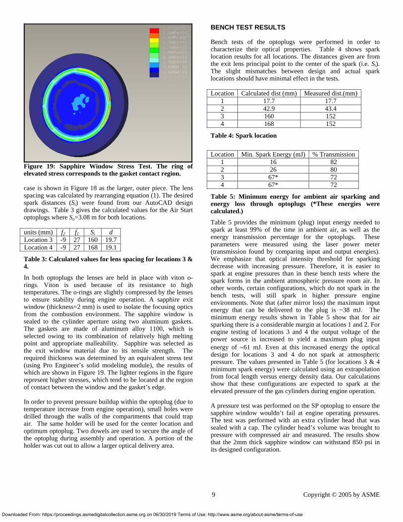
Figure 19: Sapphire Window Stress Test. The ring of elevated stress corresponds to the gasket contact region. case is shown in Figure 18 as the larger, outer piece. The lens spacing was calculated by rearranging equation (1). The desired spark distances (Si) were found from our AutoCAD design drawings. Table 3 gives the calculated values for the Air Start optoplugs where So=3.08 m for both locations. units (mm) f2 f1 Si d Location 3 -9 27 160 19.7 Location 4 -9 27 168 19.1
Table 3: Calculated values for lens spacing for locations 3 & 4.
In both optoplugs the lenses are held in place with viton o-rings. Viton is used because of its resistance to high temperatures. The o-rings are slightly compressed by the lenses to ensure stability during engine operation. A sapphire exit window (thickness=2 mm) is used to isolate the focusing optics from the combustion environment. The sapphire window is sealed to the cylinder aperture using two aluminum gaskets. The gaskets are made of aluminum alloy 1100, which is selected owing to its combination of relatively high melting point and appropriate malleability. Sapphire was selected as the exit window material due to its tensile strength. The required thickness was determined by an equivalent stress test (using Pro Engineer’s solid modeling module), the results of which are shown in Figure 19. The lighter regions in the figure represent higher stresses, which tend to be located at the region of contact between the window and the gasket’s edge. In order to prevent pressure buildup within the optoplug (due to temperature increase from engine operation), small holes were drilled through the walls of the compartments that could trap air. The same holder will be used for the center location and optimum optoplug. Two dowels are used to secure the angle of the optoplug during assembly and operation. A portion of the holder was cut out to allow a larger optical delivery area.
aded From: https://proceedings.asmedigitalcollection.asme.org on 06/30/2019 Terms of Us
BENCH TEST RESULTS Bench tests of the optoplugs were performed in order to characterize their optical properties. Table 4 shows spark location results for all locations. The distances given are from the exit lens principal point to the center of the spark (i.e. Si). The slight mismatches between design and actual spark locations should have minimal effect in the tests. Location Calculated dist (mm) Measured dist.(mm)
1 17.7 17.7 2 42.9 43.4 3 160 152 4 168 152
Table 4: Spark location
Location Min. Spark Energy (mJ) % Transmission
1 16 82 2 26 80 3 67* 72 4 67* 72
Table 5: Minimum energy for ambient air sparking and energy loss through optoplugs (*These energies were calculated.)
Table 5 provides the minimum (plug) input energy needed to spark at least 99% of the time in ambient air, as well as the energy transmission percentage for the optoplugs. These parameters were measured using the laser power meter (transmission found by comparing input and output energies). We emphasize that optical intensity threshold for sparking decrease with increasing pressure. Therefore, it is easier to spark at engine pressures than in these bench tests where the spark forms in the ambient atmospheric pressure room air. In other words, certain configurations, which do not spark in the bench tests, will still spark in higher pressure engine environments. Note that (after mirror loss) the maximum input energy that can be delivered to the plug is ~38 mJ. The minimum energy results shown in Table 5 show that for air sparking there is a considerable margin at locations 1 and 2. For engine testing of locations 3 and 4 the output voltage of the power source is increased to yield a maximum plug input energy of ∼61 mJ. Even at this increased energy the optical design for locations 3 and 4 do not spark at atmospheric pressure. The values presented in Table 5 (for locations 3 & 4 minimum spark energy) were calculated using an extrapolation from focal length versus energy density data. Our calculations show that these configurations are expected to spark at the elevated pressure of the gas cylinders during engine operation. A pressure test was performed on the SP optoplug to ensure the sapphire window wouldn’t fail at engine operating pressures. The test was performed with an extra cylinder head that was sealed with a cap. The cylinder head’s volume was brought to pressure with compressed air and measured. The results show that the 2mm thick sapphire window can withstand 850 psi in its designed configuration.
9 Copyright © 2005 by ASME
e: http://www.asme.org/about-asme/terms-of-use
Downlo
CONCLUSIONS This paper presents the design methodology used to develop a practical open-path laser ignition system for single cylinder operation of a large-bore natural gas engine. CFD modeling was employed to find an optimal spark location within the cylinder volume. Of the four locations considered, the CFD results show that placing the laser 2” off-center toward the intake side of the cylinder attains the optimal burn rate. The upcoming experiments (to be presented in the 2nd paper of this 2 paper series) will investigate each of the four spark locations to examine the potential benefits of laser ignition. Beam path requirements were considered as well as vibration and thermal effects in order to determine where and how to mount the laser head and laser power supply. Finally, an optoplug was designed for each of our 4 test locations. Each 2-lens plug was designed using standard optical imaging lens equations. The optoplugs have undergone preliminary bench testing, which has proven their efficacy. The plugs are similar in size to conventional spark plugs and use the same threading so that they may be easily integrated on-engine.
ACKNOWLEDGMENTS This work was funded by the Gas Research Institute with co-funding and in-kind support from Altronic, Inc. The authors acknowledge key technical contributions from Morgan DeFoort, Ryan Shannon, Keri Schafer, and Aaron Zimenoff. The authors also acknowledge the technical support from Big Sky Laser and Pioneer Engineering.
REFERENCES 1 Dale, J.D., Smy, P.R., Clements, R.M., “Laser Ignited Internal Combustion Engine – An Experimental Study,” SAE Paper 780329, 1978. 2 McMillian, M., Richardson, S., Woodruff, S.D., Tran, P. and McIntyre, D., “Laser-Spark Ignition for Natural Gas Fueled Reciprocating Engines,” Gas Machinery Conference 2003, DOE Research Review, October 5-8, 2003. 3 Kopecek, H., Charareh, S., Lackner, M., Forsich, C., Winter, F., Klausner, J., Herdin, G., and Wintner, E., 2003, “Laser Ignition of Methane-Air Mixtures at High Pressures and Diagnostics,” Spring Technical Conference ASME, Salzburg, Austria, Paper No. ICES2003-614, 2003. 4 Olsen, D.B., Hutcherson, G.C., Willson, B.D., and Mitchell, C.E., “Development of the Tracer Gas Method for Large Bore Natural Gas Engines: Part 2 – Measurement of Scavenging Parameters”, Journal of Engineering for Gas Turbines and Power, Vol. 124, Issue 3 pp. 686-694, July 2002. 5 Olsen, D.B. and Willson, B.D., “The Effect of Parametric Variations on Formaldehyde Emissions from a Large Bore Natural Gas Engine”, Proceedings ASME-ICE Spring Technical Conference, ICE-Vol. 38, Paper No. 2002-ICE-446, 2002.
aded From: https://proceedings.asmedigitalcollection.asme.org on 06/30/2019 Terms of Use:
6 Brown, J., Mizia, J., Olsen, D.B. and Willson, B.D., “On-Engine Demonstration of Micro-Pilot Ignition System for a Cooper-Bessemer GMV-4TF”, Proceedings ASME-ICE Fall Technical Conference, Sept. 2003. 7 Kim, G.H., Kirkpatrick, A., and Mitchell, C., "Computational Modeling of Natural Gas Injection in a Large Bore Engine", J. of Engineering For Gas Turbines and Power, 126, pp 256-264. 8 Kirkpatrick, A., Li, Y., Mitchell, C. and Willson, B., “Analytical and Computational Modeling of High Pressure Gas Injection”, Proceedings ASME ICE Fall Technical Conference, Vol. 37-2, Paper No. 2001-ICE-410, 2001. 9 Kirkpatrick, A., Kim, G.H., and Mitchell, C., "CFD Simulation of Fluid Flow and Combustion in a Two Stroke Large Bore Engine", CIMAC 2004 Congress, Kyoto, Japan, June 2004. 10 Hecht, E., Optics Fourth Edition, Addison Wesley, San Francisco, CA, pp. 168, Chap. 5, 2002.
10 Copyright © 2005 by ASME
http://www.asme.org/about-asme/terms-of-use
Related Documents