Development of an automatic robotic cleaning system for photovoltaic plants Student: Nawaf Albaqawi ID No: 10330652 Bachelor of Engineering Technology (Electrical) SCCC701 Engineering Development Project Academic Supervisor: Alireza Gheitasi Tutor: Debbie Hogan 2014

Welcome message from author
This document is posted to help you gain knowledge. Please leave a comment to let me know what you think about it! Share it to your friends and learn new things together.
Transcript

SCCC701 Engineering Development Project | P a g e
Development of an automatic robotic cleaning system for photovoltaic plants
Student: Nawaf Albaqawi
ID No: 10330652
Bachelor of Engineering Technology (Electrical)
SCCC701 Engineering Development Project
Academic Supervisor: Alireza Gheitasi
Tutor: Debbie Hogan
2014

SCCC701 Engineering Development Project | P a g e i
PROJECT DETAILS
STUDENT
Name: Nawaf Albaqawi
Email: [email protected]
Phone: 021794441
ACADEMIC SUPERVISORS
Name: Alireza Gheitasi
Email: [email protected]
Direct Work Line: 07-8348800 ext 3143
TUTOR
Name: Debbie Hogan
Email: [email protected]
Direct Work Line: 07-834 8800 ext 7839
SCCC701 Engineering Development Project | P a g e ii
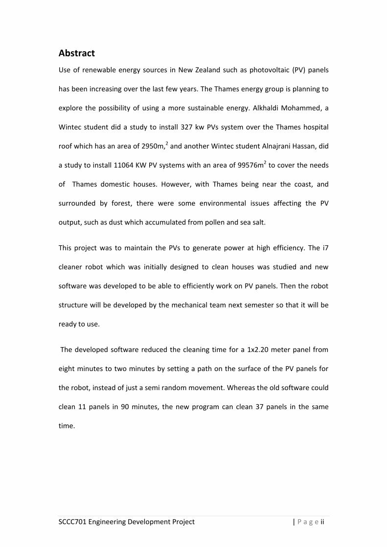
Abstract
Use of renewable energy sources in New Zealand such as photovoltaic (PV) panels
has been increasing over the last few years. The Thames energy group is planning to
explore the possibility of using a more sustainable energy. Alkhaldi Mohammed, a
Wintec student did a study to install 327 kw PVs system over the Thames hospital
roof which has an area of 2950m,2 and another Wintec student Alnajrani Hassan, did
a study to install 11064 KW PV systems with an area of 99576m2 to cover the needs
of Thames domestic houses. However, with Thames being near the coast, and
surrounded by forest, there were some environmental issues affecting the PV
output, such as dust which accumulated from pollen and sea salt.
This project was to maintain the PVs to generate power at high efficiency. The i7
cleaner robot which was initially designed to clean houses was studied and new
software was developed to be able to efficiently work on PV panels. Then the robot
structure will be developed by the mechanical team next semester so that it will be
ready to use.
The developed software reduced the cleaning time for a 1x2.20 meter panel from
eight minutes to two minutes by setting a path on the surface of the PV panels for
the robot, instead of just a semi random movement. Whereas the old software could
clean 11 panels in 90 minutes, the new program can clean 37 panels in the same
time.

SCCC701 Engineering Development Project | P a g e iii
Abbreviations
DC – Direct current
kW – Kilowatt
m2 – Square meter
µc – Microcontroller
PV – Photovoltaic
V1 – The name of the cleaning robotic system
Glossary
Array – Is a way of photovoltaic (PV) modules electrical connection that providing a
single electrical output.
Direct current (DC) – The PV systems genera electricity in DC, which is defined as the
electricity flow, continues through conductors.
Kilowatt (kW) – A unit of electrical power equal to 1,000 watts.
Photovoltaic – is technology to generating power, which uses a semiconductor to
convert light into electricity.
Watt – A unit of measurement of electric power.
SCCC701 Engineering Development Project | P a g e iv
Table of Contents
PROJECT DETAILS ............................................................................................................ i
Abstract .......................................................................................................................... ii
Abbreviations ................................................................................................................ iii
Glossary ......................................................................................................................... iii
Table of Contents .......................................................................................................... iv
Table of Figures .............................................................................................................. v
Table of Tables .............................................................................................................. vi
1. Introduction ............................................................................................................ 1
2. Literature review .................................................................................................... 2
2.1 Growth of PV power usage ...................................................................................... 3
2.2 Environmental factors affecting efficiency of PV panels ......................................... 3
2.2.1 Shadow .............................................................................................................. 3
2.2.2 Snow .................................................................................................................. 4
2.2.3 Externally high temperature ............................................................................. 4
2.2.4 Dust, dirt, bird droppings, pollen and sea salt .................................................. 4
2.3 Effects of dust on solar panel efficiency .................................................................. 5
2.4 Methods used to clean PV panels ............................................................................ 6
2.4.1 Heliotex technology .......................................................................................... 6
2.4.2 Electrostatics cleaning ....................................................................................... 8
2.4.3 Robotic cleaning solutions ................................................................................ 9
3. Methodology ........................................................................................................ 13
3.1 Analyses of the i7 cleaning robot ........................................................................... 13
3.1.1 Analyses of the physical shape and internal components .............................. 13
3.1.2 Analysis of the movement pattern and the cleaning mechanism .................. 14
3.2 The mechanical stability testing ............................................................................ 15
3.3 Software development .......................................................................................... 16
3.3.2 The program development ............................................................................. 17
3.3.3 Conditions based on the sensors .................................................................... 18
3.3.4 Testing the operation of the new program ..................................................... 20
4. Result and discussion ............................................................................................ 22
4.1 The mechanical construction testing result ........................................................... 22
4.1.1 Testing the cleaning and the movement pattern of the robot on zero angle 22
4.1.2 The correct angle for the robot to be stable ................................................... 23
4.1.3 Testing the robot on a 45o angle ..................................................................... 24
4.1.4 Flipping angles ................................................................................................. 25
4.1.5 Crossing between two boards ......................................................................... 25

SCCC701 Engineering Development Project | P a g e v
4.1.6 Experiments to stop the robot flipping ........................................................... 26
4.2 The prototype testing result .................................................................................. 27
4.2.1 The forward path............................................................................................. 27
4.2.2 Rotation 180o right or left ............................................................................... 28
4.2.3 Right edge detected ........................................................................................ 28
4.2.4 Ending the cleaning process ............................................................................ 29
5. Conclusion and recommendation ........................................................................ 30
6. Student Declaration .............................................................................................. 31
7. References ............................................................................................................... 32
8. Appendix .................................................................................................................. 34
Appendix A The full codes of the developed software ................................................ 34
Appendix B The specification of the cleaner robot ..................................................... 42
Appendix C Photos of the robot’s movement process during cleaning ...................... 43
Table of Figures
Figure 2-1: Thames location over New Zealand. ........................................................... 2
Figure 2-2: Heliotex cleaning technology using water and soap to clean the surface of
PV panels (Heliotex, 2013). .................................................................................... 6
Figure 2-3: Structure of PVs system that uses electrostatic cleaning (Jalbuena, 2010).
................................................................................................................................ 8
Figure 2-4: Traveling system of robot V1.0 head along of the panel arrays (Anderson,
2012) ...................................................................................................................... 9
Figure 2-5: Drive Wheel Paired Via a Chain (Anderson, 2012). ................................... 10
Figure 2-6: The results of a single pass of the V1 cleaning robot ................................ 10
Figure 2-7: Sun Brush full automatic cleaning over solar panels (Siemens, 2013)...... 11
Figure 2-8: The i7 house-cleaning robot. ..................................................................... 12
Figure 3-1: i7 Cleaning robot components. ................................................................. 13
Figure 3-2: Moving in the zigzag mode ........................................................................ 14
Figure 3-3: Moving in the spiral mode. ........................................................................ 14
Figure 3-4: The i7 cleaning robot’s bins (Pursonic i7 vacuum cleaner robot, 2012). .. 14
Figure 3-5: Cleaning experiment. ................................................................................. 15
Figure 3-6: The new constant path of the cleaner robot. ........................................... 16
Figure 3-7: The searching path of the robot. ............................................................... 17
Figure 3-8: The prototype of the new program represented by LED lights and
controlled by Arduino microcontroller. ............................................................... 20
Figure 3-9: Wiring diagram of the prototype. ............................................................. 21
Figure 4-1: Soft powder left after cleaned the board. ................................................. 22
SCCC701 Engineering Development Project | P a g e vi
Figure 4-2: The dirt bin storage. .................................................................................. 22
Figure 4-3: The robot tested on 19.4 degree angle. .................................................... 23
Figure 4-4: Tip supported on the front of the robot. .................................................. 24
Figure 4-5: The robot flipping over when it climbed on 45 degree angle. .................. 24
Figure 4-6: Starting flipping angle which is 23 degree angle. ...................................... 25
Figure 4-7: The robot crossing between two boards. ................................................. 25
Figure 4-8: Extra weight added to the robot. .............................................................. 26
Figure 4-9: The left edge detected and the robot back to the path. ........................... 27
Figure 4-10: The front edge detected and the robot rotated. .................................... 27
Figure 4-11: Rotation 180 degree to the right. ............................................................ 28
Figure 4-12: Rotation 180 degree to the left. .............................................................. 28
Figure 4-13: The right edge detected and the robot back to the path. ...................... 28
Figure 4-14: Detecting the End and back to the starting point. .................................. 29
Table of Tables
Table 3-1 The truth table of the new program sensors and actuators action. ........... 18
Table 3-2 Existing i7 cleaning robot motors control movement. ................................ 19

SCCC701 Engineering Development Project | P a g e 1
1. Introduction
Photovoltaic panel production has increased globally in response to the growing
demand for solar energy. This has been the result of an increased awareness of the
damage to the environment that using fossil fuel sources has had over the years. The
rate of solar panel usage in New Zealand has increased 370% since 20011 (Sustainble
Electricity Association New Zealand, 2013).
There are many factors that affect PV power efficiency, such as shadow, snow, high
temperatures, pollen, bird droppings, sea salt, dust and dirt. The main factor that
affects a PV panel’s efficiency is dust, which can reduce its efficiency by up to 50%,
depending on the environment.
As the Thames Energy Group eager to explore the possibility of using a more
sustainable power source. The possibility of installing many PV panels into the area
brought about the need to consider how to increase long term efficiency by the
regular removal of debris from the PV panels. In particular, dust which is made up of
pollen, sea salt and dirt particles.
This project investigated the possibility of using the i7 cleaning robots (usually used
for house cleaning) to remove dust, sea salt and pollen from the surfaces of PV
panels.
The limitation of this project was that the new software was tested in simulated
conditions, but has not been used in actual environmental conditions in the Thames
township.
SCCC701 Engineering Development Project | P a g e 2
2. Literature review
For solar power to be efficient, elimination of some environmental effects is needed.
This section will discuss the PVs’ efficiency which is influenced by the environment,
especially the effects of dust. The previous automatic cleaning methods that were
used have been evaluated with the purpose of developing an i7 cleaning robot which
will be efficient at removing dust and pollen from the PV panel’s surface.
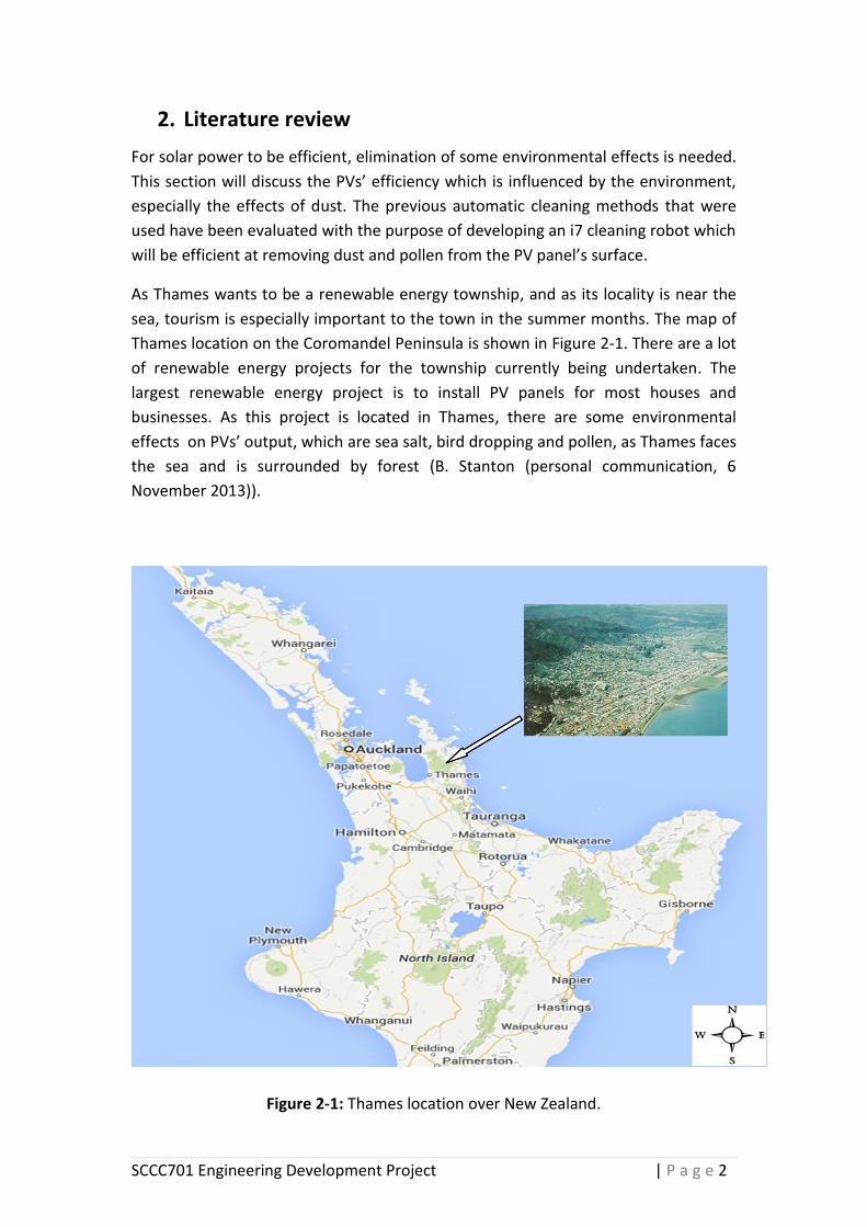
As Thames wants to be a renewable energy township, and as its locality is near the
sea, tourism is especially important to the town in the summer months. The map of
Thames location on the Coromandel Peninsula is shown in Figure 2-1. There are a lot
of renewable energy projects for the township currently being undertaken. The
largest renewable energy project is to install PV panels for most houses and
businesses. As this project is located in Thames, there are some environmental
effects on PVs’ output, which are sea salt, bird dropping and pollen, as Thames faces
the sea and is surrounded by forest (B. Stanton (personal communication, 6
November 2013)).
Figure 2-1: Thames location over New Zealand.
SCCC701 Engineering Development Project | P a g e 3
2.1 Growth of PV power usage
PV power is one of the most efficient renewable sources of energy. The use of PV
power energy is growing worldwide. In New Zealand it has been reported that the
installations of PV panel systems have increased dramatically by 370% since 2011,
which has also led to a need to find a way to effectively keep the PV panels clean
(Sustainble Electricity Association New Zealand, 2013). The current capacity of an
installed PV system in New Zealand is 8.2MW (Sustainble Electricity Association New
Zealand, 2013). Lower cost and ease of use are the two key drivers behind the
growth of PV panels in New Zealand (Sustainble Electricity Association New Zealand,
2013). In other countries the situation is the same; for example, the residential PV
capacity installed in the United States is projected to grow from 1.4 GW in 2010 to
10.6 GW by 2016 (Clean Energy Prize, 2013).
2.2 Environmental factors affecting efficiency of PV panels
Solar power generation can be influenced by many factors. The major factors that
reduce or impede the generation of power for the PV panels are; shadows, snow,
high temperatures, dust, dirt, bird droppings, pollen and sea salt. The environmental
factors affecting solar energy generation will be discussed below.
2.2.1 Shadow
When installing PV panels, it is important to consider where shadows fall (Sullivan,
2011). When PV panels are not installed correctly, their output can be reduced. To
avoid reducing the efficiency of the PV panel, the following should be considered:
The dimensions of any shadow at different times of the year
The structure and angle of the PV panel
Tracking how the shadow influences the panel (Sullivan, 2011).

SCCC701 Engineering Development Project | P a g e 4
2.2.2 Snow
PV panels can still generate electricity under a light snowfall, but once the snow
completely blocks out the sun radiation, the PV panels will stop generating electricity
(Adele, 2010). Further, if one area of a solar panel is completely covered by snow,
the rest of the panel can stop functioning because of the way the solar cells are
wired together (Adele, 2010). In this project snow was not considered because it has
rarely snowed in Thames.
2.2.3 Externally high temperature
When panels reach high temperatures, power efficiency drops. Hill reported that the
efficiency of energy output drops by 1.1% for every extra degree in Celsius once the
PV panel temperature reaches 42 (Hill, 2013). In this project extremely high
temperatures were not be considered, as the temperature in Thames rarely reaches
this level.
2.2.4 Dust, dirt, bird droppings, pollen and sea salt
Accumulated dust on the surfaces of PV panels can come from many different
sources, and can have a big impact on electricity production. The efficiency of the
solar panel can be reduced by up to 50% in a dusty environment, as this interferes
with the amount of direct sunlight received to the PV array (Kasim, 2010). The rate
of dust in Thames is low, but annual cleaning is still recommended to remove dust
that has accumulated over this time. Pollen from flowering trees, bird droppings and
salt spray from the sea are particular problems for the Thames area (B. Stanton
(personal communication, 6 November 2013)).

SCCC701 Engineering Development Project | P a g e 5
2.3 Effects of dust on solar panel efficiency
The power output generated by PV panels is known to suffer power efficiency losses
over time due to accumulation of dust and other dirt. In the Middle East, India and
Australia, PV power output is significantly affected by the accumulation of dust on
the surfaces of PV arrays. In Saudi Arabia, the accumulation of dust decreases the
power production by up to 50% (Adinoyi, 2013). Research done by an engineering
student in Baghdad in 2010 found that the transmittance decreased over a one-
month period by approximately 50% on average, due to the natural deposition of
dust on PV panels (Kasim, 2010).
As the growth of PV panel use increases, so does the need for monitoring and
cleaning the panels’ surfaces. The frequency of cleaning the PV panels depends on
the environment of the solar installation. A New Zealand company suggests solar
panels should be cleaned once to twice a year in the New Zealand environment (B.
Stanton (personal communication, 6 November 2013)).
SCCC701 Engineering Development Project | P a g e 6
2.4 Methods used to clean PV panels
At present, PV panels can be cleaned manually and automatically. Over time, manual
cleaning is more costly compared to automatic cleaning. This project considered
some different cleaning technologies available on the market today, such as; the
Heliotex rinse, electrostatic cleaning, the V1 cleaning robot system and the SunBrush
robot system. These cleaning methods were chosen to review, so as to determine
whether the development of the i7 house-cleaning robot will work on a PV panel’s
surface. Furthermore, the use of PV panels cleaning robotics has been expanding
over the last few years to reduce the need for manual cleaning (Anderson, 2012).
The cleaning methods are explained below:
2.4.1 Heliotex technology
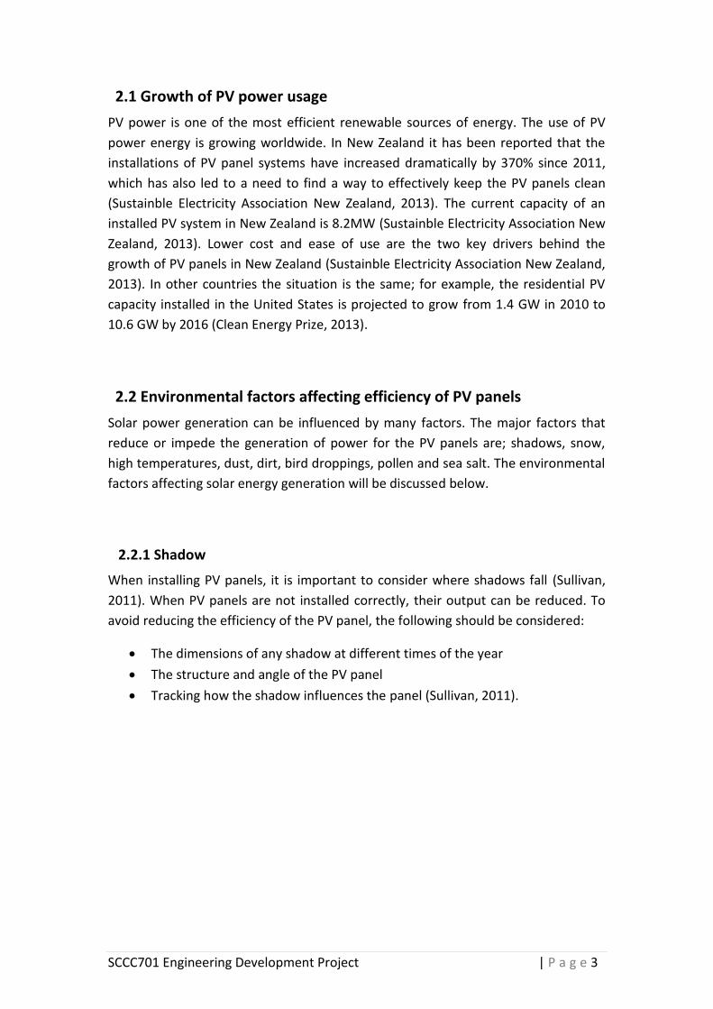
Heliotex is an automatic cleaning system that washes and rinses solar panel surfaces.
The cleaning system can be programmed whenever it is necessary, depending on the
environment (Heliotex, 2013). It does not require any further attention except the
replacement of the water filters and the occasional refilling of the soap concentrate.
It contains a five-gallon reservoir for soap, which does not cause any damage to the
solar panels and roofing materials (Heliotex, 2013).
The Heliotex system sources the water from the residence via a hose or pipe
connected to the pump and attached to nozzles on the solar panel surface without
causing rubbing. See Figure 2-2.
The Heliotex system can be installed for any size or number of solar panels. The cost
of installation for the Heliotex is US$2,258.00 to cover 50 PV panels (Conduit, 2014).
Figure 2-2: Heliotex cleaning technology using water and soap to clean the surface of PV panels (Heliotex, 2013).

SCCC701 Engineering Development Project | P a g e 7
The advantages and disadvantages of using the Heliotex cleaning system are listed
below:
Advantages:
Good for areas with ready access to water.
Improves the effectiveness of the PV panels after being washed by almost
100%.
The Heliotex cleaning system is reliable (warranted for 10 years).
Disadvantages:
Expensive equipment such as the soap, hoses and pumps which are required.
Requires ready access to plenty of water.
Needs regular checking for the water and soap residue build up.
The soap may affect the environment of plants.

SCCC701 Engineering Development Project | P a g e 8
2.4.2 Electrostatics cleaning
Electrostatics cleaning technology is named “Harvesting electricity”. This cleaning
technology was first developed by scientists to solve the problem of dust deposits on
the surfaces of PVs located on Mars. This technology can also be used in dry dusty
areas on Earth. Electrostatic charge material is used on a transparent plastic sheet or
glass that covers the solar panels. Sensors monitor dust levels and activate the
system into cleaning mode (Jalbuena, 2010).
The dust is shaken off the solar panels when an electrically charged wave breaks
over the surface material. This is not a safe way for homeowners who are using solar
panels because the panel shakes which may loosen its connection to the roof and it
could fall down and cause injury. However, it is an effective solution for larger
systems elsewhere. The structure of the panels is strong and flexible to avoid
breakage that may be caused by shaking, as shown in Figure 2-3 (Jalbuena, 2010).
In two minutes this system can remove up to 90% of dust from the surfaces of the
PV panels by sending an electrical dust deterring wave which causes the dust to fall
off onto the ground. (Jalbuena, 2010).However, this system is not going to remove
dust when it gets wet, or if it is in a moist environment. The movement of the wave
mechanism requires only a small amount of electricity which makes it a power
efficient system however at present; the worldwide usage of the harvesting system
is only 4% (Jalbuena, 2010)
Figure 2-3: Structure of PVs system that uses electrostatic cleaning (Jalbuena, 2010).

SCCC701 Engineering Development Project | P a g e 9
2.4.3 Robotic cleaning solutions
The section below discusses and analyses cleaning robots, such as the V1 cleaning
fixed robot and the SunBrush cleaner robot, to develop a better solution for using
the i7 vacuum-cleaning robot on PV panels.
2.4.3.1 The PV cleaner V1 robot
The robotised V1 system was designed for cleaning the surface of the PV panels
automatically to maximize the output of energy (Anderson, 2012). The V1 robot is
composed of a cleaning head and a drive system. The cleaning head has two
cylindrical brushes traveling upward and downward along the panel surface edges by
a pair of motorized trolleys to generate a clean PV panel as shown in Figure 2-4
(Anderson, 2012). A guide cable is connected to each drive trolley to control the
movement of the cleaning head and prevent unwanted rotation (Anderson, 2012).
Figure 2-4: Traveling system of robot V1.0 head along of the panel arrays (Anderson, 2012).
SCCC701 Engineering Development Project | P a g e 10
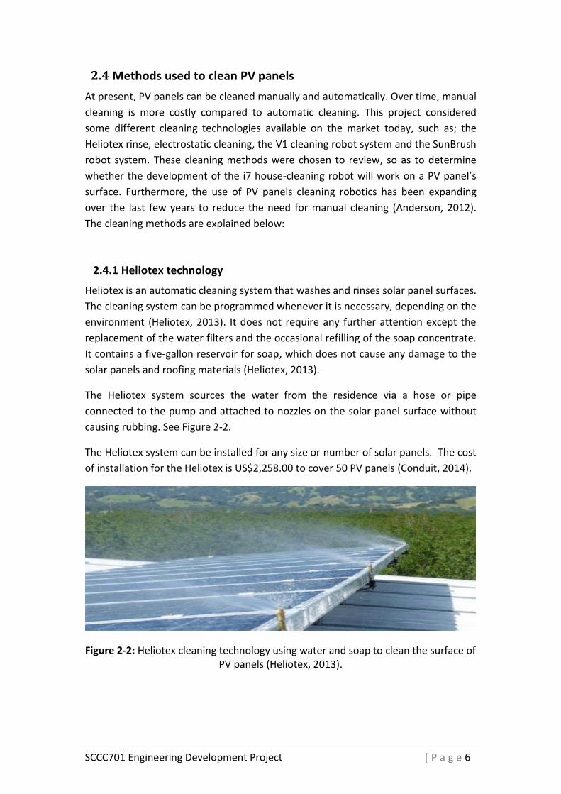
The drive system consists of three main components of motion: the top and bottom
trolleys and the cleaning head. The top and bottom trolleys use a 12V DC motor, to
provide motion to the cleaning system. The top and bottom can be controlled
independently along the panel rows. Contrinex 500 M30 sensors located on the
trolley frame detect the edges of the panel, giving a command to the control system
to slow or stop the motion when the trolley reaches the end of the panel array. The
drive wheels of each trolley are composed of two pairs. Each pair is linked via a chain
as shown in Figure 2-5. The wheels were designed in pairs to avoid falling down
when it is crossing gaps between two panels (Anderson, 2012).
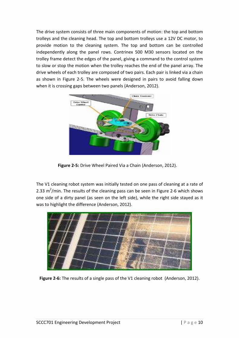
The V1 cleaning robot system was initially tested on one pass of cleaning at a rate of
2.33 m2/min. The results of the cleaning pass can be seen in Figure 2-6 which shows
one side of a dirty panel (as seen on the left side), while the right side stayed as it
was to highlight the difference (Anderson, 2012).
Figure 2-6: The results of a single pass of the V1 cleaning robot (Anderson, 2012).
Figure 2-5: Drive Wheel Paired Via a Chain (Anderson, 2012).
SCCC701 Engineering Development Project | P a g e 11
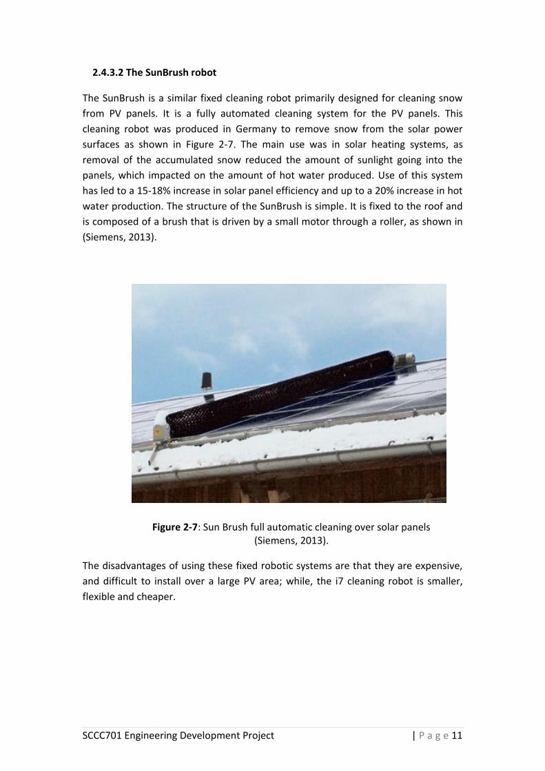
2.4.3.2 The SunBrush robot
The SunBrush is a similar fixed cleaning robot primarily designed for cleaning snow
from PV panels. It is a fully automated cleaning system for the PV panels. This
cleaning robot was produced in Germany to remove snow from the solar power
surfaces as shown in Figure 2-7. The main use was in solar heating systems, as
removal of the accumulated snow reduced the amount of sunlight going into the
panels, which impacted on the amount of hot water produced. Use of this system
has led to a 15-18% increase in solar panel efficiency and up to a 20% increase in hot
water production. The structure of the SunBrush is simple. It is fixed to the roof and
is composed of a brush that is driven by a small motor through a roller, as shown in
(Siemens, 2013).
The disadvantages of using these fixed robotic systems are that they are expensive,
and difficult to install over a large PV area; while, the i7 cleaning robot is smaller,
flexible and cheaper.
Figure 2-7: Sun Brush full automatic cleaning over solar panels (Siemens, 2013).
SCCC701 Engineering Development Project | P a g e 12
2.4.3.3 Potential cleaning robot
After looking at all the cleaning methods, the idea came to develop the i7 vacuum
robot, which was designed to clean floors in houses, to work on solar panel surfaces.
The i7 cleaning vacuum robot was chosen for this project because it is flexible, small,
and has an intelligent control system.
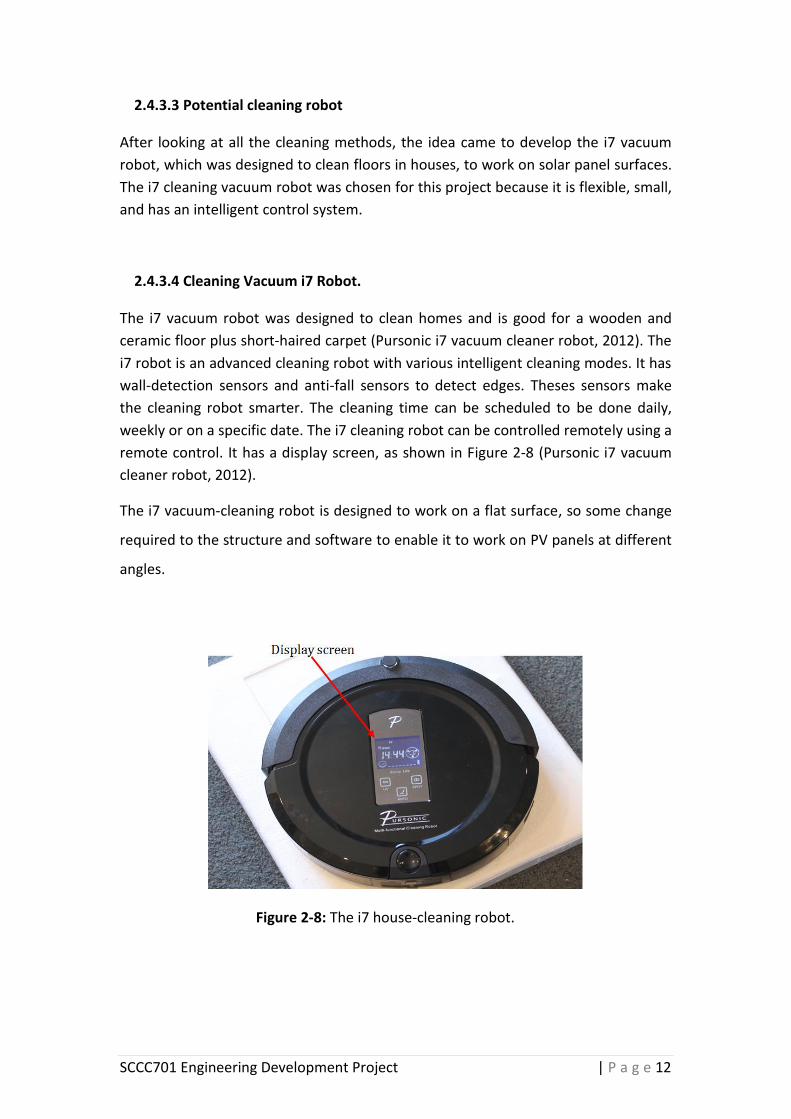
2.4.3.4 Cleaning Vacuum i7 Robot.
The i7 vacuum robot was designed to clean homes and is good for a wooden and
ceramic floor plus short-haired carpet (Pursonic i7 vacuum cleaner robot, 2012). The
i7 robot is an advanced cleaning robot with various intelligent cleaning modes. It has
wall-detection sensors and anti-fall sensors to detect edges. Theses sensors make
the cleaning robot smarter. The cleaning time can be scheduled to be done daily,
weekly or on a specific date. The i7 cleaning robot can be controlled remotely using a
remote control. It has a display screen, as shown in Figure 2-8 (Pursonic i7 vacuum
cleaner robot, 2012).
The i7 vacuum-cleaning robot is designed to work on a flat surface, so some change
required to the structure and software to enable it to work on PV panels at different
angles.
Figure 2-8: The i7 house-cleaning robot.
SCCC701 Engineering Development Project | P a g e 13
3. Methodology
This section describes the methodology used to modify the i7 cleaning robot to clean
the PV panels’ surfaces. The methods for developing the cleaner robot are divided
into 3 sections:
1) Analyses of the i7 cleaning robot
2) Mechanical stability analyses
3) Software development
In the first section components of the i7 cleaning robot have been identified. This
analysis was needed to enable the mechanical improvement and the software
improvement. In the mechanical analysis section the robot was tested at different
angles to find the most stable movement for the new software, also to address the
issues needed to be improved by the mechanical team. In the software section new
software was developed and tested to enable the robot to work on the surfaces of
PV panels.
3.1 Analyses of the i7 cleaning robot
Different components of the i7 cleaner robot were analyzed in order to understand
the process of cleaning, based on the current software. This analysis was to
understand the mechanism of operation of the robot to design new software that
enables the robot to work effectively on the surface of PV panels.
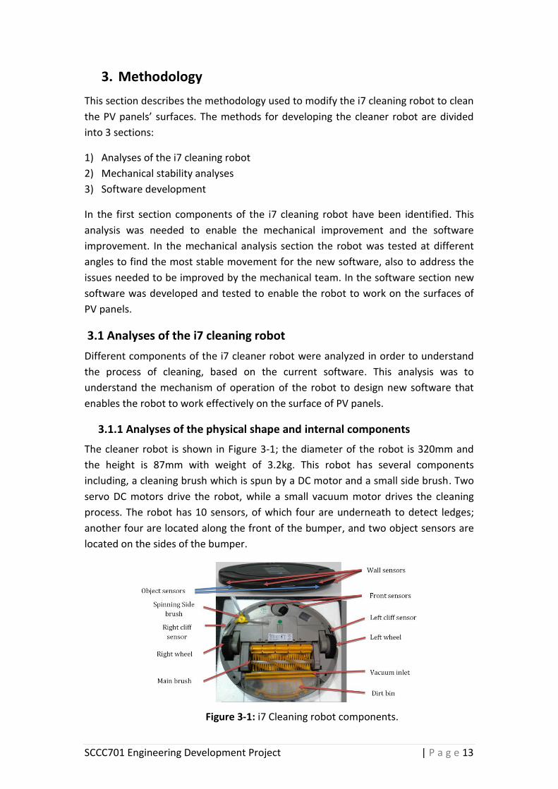
3.1.1 Analyses of the physical shape and internal components
The cleaner robot is shown in Figure 3-1; the diameter of the robot is 320mm and
the height is 87mm with weight of 3.2kg. This robot has several components
including, a cleaning brush which is spun by a DC motor and a small side brush. Two
servo DC motors drive the robot, while a small vacuum motor drives the cleaning
process. The robot has 10 sensors, of which four are underneath to detect ledges;
another four are located along the front of the bumper, and two object sensors are
located on the sides of the bumper.
Figure 3-1: i7 Cleaning robot components.

SCCC701 Engineering Development Project | P a g e 14
3.1.2 Analysis of the movement pattern and the cleaning mechanism
The i7 cleaning robot follows no preset path; it is controlled by a microcontroller
(µc). The methods of the i7 cleaning robot’s movement are zigzag, spiral and anti-fall
as shown in Figures 3-2 and 3-3. When the robot is in the zigzag mode it travels
straight for a set distance, then changes direction, or also will change direction if it
detects an object. At a set distance it will go into the spiral mode, where the robot
spirals on one spot for a short time, then goes back to the zigzag mode.
Dirt, pollen and dust are scoured by the brush into the main dirt bin and the soft
dust is vacuumed through the inlet vacuum as shown in Figure 3-4. For more
specifications of the i7 cleaning robot see appendix B.
Figure 3-4: The i7 cleaning robot’s bins (Pursonic i7 vacuum cleaner robot, 2012).
Figure 3-2: Moving in the zigzag mode. Figure 3-3: Moving in the spiral mode.
SCCC701 Engineering Development Project | P a g e 15
3.2 The mechanical stability testing
In this section the i7 cleaning robot’s stability was tested at different angles to find
the most stable movement for the new software. Also to find the stable angle for the
robot to work on and the maximum angle that it is able to operate at. The processes
of the stability test are listed below:
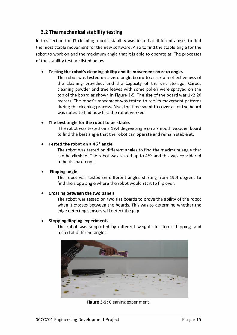
Testing the robot’s cleaning ability and its movement on zero angle. The robot was tested on a zero angle board to ascertain effectiveness of the cleaning provided, and the capacity of the dirt storage. Carpet cleaning powder and tree leaves with some pollen were sprayed on the top of the board as shown in Figure 3-5. The size of the board was 1×2.20 meters. The robot’s movement was tested to see its movement patterns during the cleaning process. Also, the time spent to cover all of the board was noted to find how fast the robot worked.
The best angle for the robot to be stable. The robot was tested on a 19.4 degree angle on a smooth wooden board to find the best angle that the robot can operate and remain stable at.
Tested the robot on a angle. The robot was tested on different angles to find the maximum angle that can be climbed. The robot was tested up to and this was considered to be its maximum.
Flipping angle The robot was tested on different angles starting from 19.4 degrees to find the slope angle where the robot would start to flip over.
Crossing between the two panels The robot was tested on two flat boards to prove the ability of the robot when it crosses between the boards. This was to determine whether the edge detecting sensors will detect the gap.
Stopping flipping experiments The robot was supported by different weights to stop it flipping, and tested at different angles.
Figure 3-5: Cleaning experiment.
SCCC701 Engineering Development Project | P a g e 16
3.3 Software development
As explained in Section 3.1.2, the i7 cleaner robot was moving semi randomly, and
that caused higher power consumption. The existing software is locked by the
manufacturer so that new software needed to be developed. The new software is
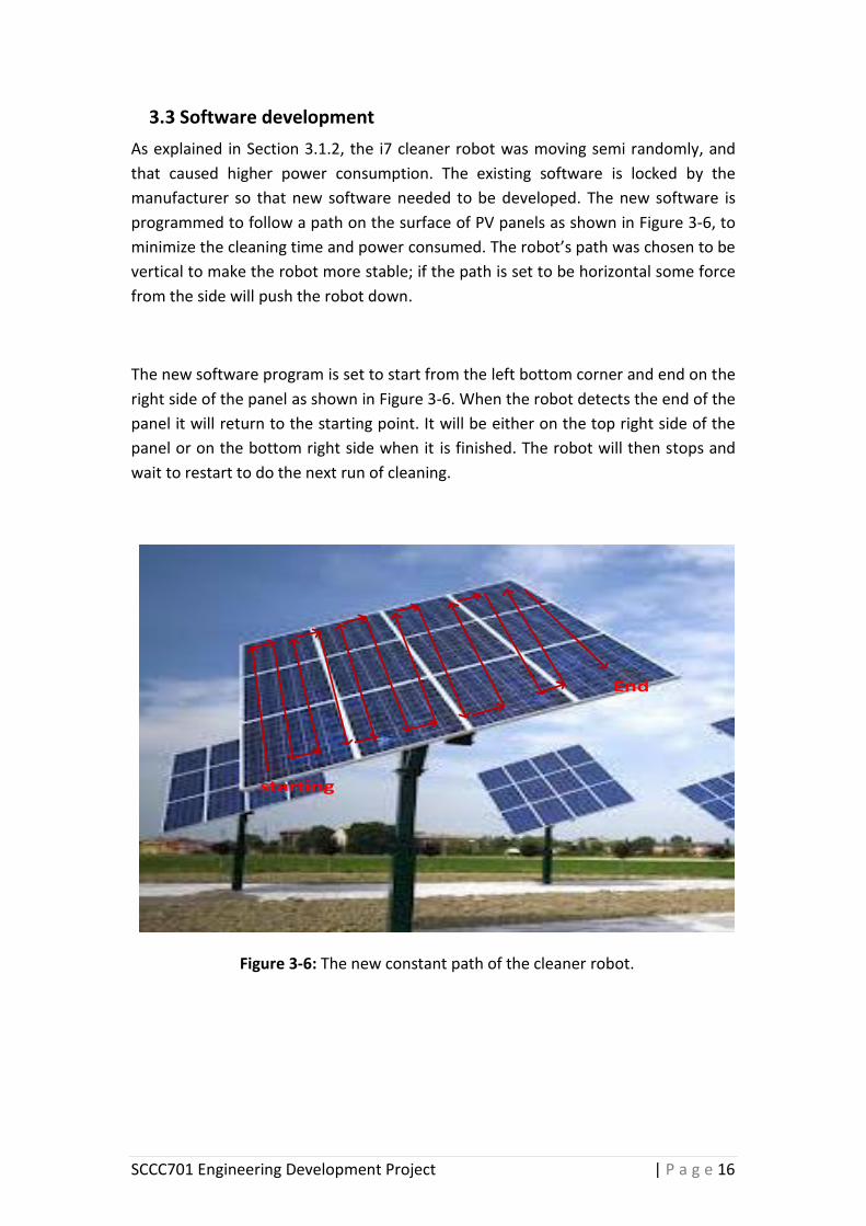
programmed to follow a path on the surface of PV panels as shown in Figure 3-6, to
minimize the cleaning time and power consumed. The robot’s path was chosen to be
vertical to make the robot more stable; if the path is set to be horizontal some force
from the side will push the robot down.
The new software program is set to start from the left bottom corner and end on the
right side of the panel as shown in Figure 3-6. When the robot detects the end of the
panel it will return to the starting point. It will be either on the top right side of the
panel or on the bottom right side when it is finished. The robot will then stops and
wait to restart to do the next run of cleaning.
starting
End
Figure 3-6: The new constant path of the cleaner robot.

SCCC701 Engineering Development Project | P a g e 17
3.3.2 The program development
The new program process for the cleaning robot is shown in the flow diagram in
Figure 3-7 and the full codes of the program are indicated in appendix A. This
program is an alternative to the i7 cleaning robot program. The new program has
these considerations:
1. Follow the sequence process as shown in Figure 3-7
2. By using anti-fall sensors the ledges of the PVs are recorded so that it
does not fall off
3. Returns to the starting point after finishing the cleaning process
Idle
Straight
Obstacle
front
Obstacle
left
Obstacle
right
Stop, Turn
Left 4cm
Stop, Turn
Right 4 cm,
Stop, back 10 cm
Rotate 180°
right
Stop, back 10 cm
Rotate 180°
left
Obstacle
front
Obstacle
left
Obstacle
right
Stop, Turn
Left 4cm
Stop, Turn
Right 4 cm,
Straight
Back to original place
Then
Front sensor & right
sensor engaged
Front sensor & left
sensor engaged
Figure 3-7: The searching path of the robot.
SCCC701 Engineering Development Project | P a g e 18
3.3.3 Conditions based on the sensors
This section explains the sensors’ detection and the robot directions based on the
searching path in the flow diagram as demonstrated in Section 3.4.2. In this
development three main underneath sensors were used, which are the front, the left
and the right sensors. Other sensors were not necessary when the robot was used
on the PV panels. Table 3-1 points out each sensor’s working and the robot’s
direction. These sensors were used to control the movement of the robot by using
actuators. There are two possible situations for each sensor which are high or low. A
high situation happens when one of the robot sensors detects the ledge and the low
situation means the sensor has not detected an edge. These situations are based on
the sensor’s signal.
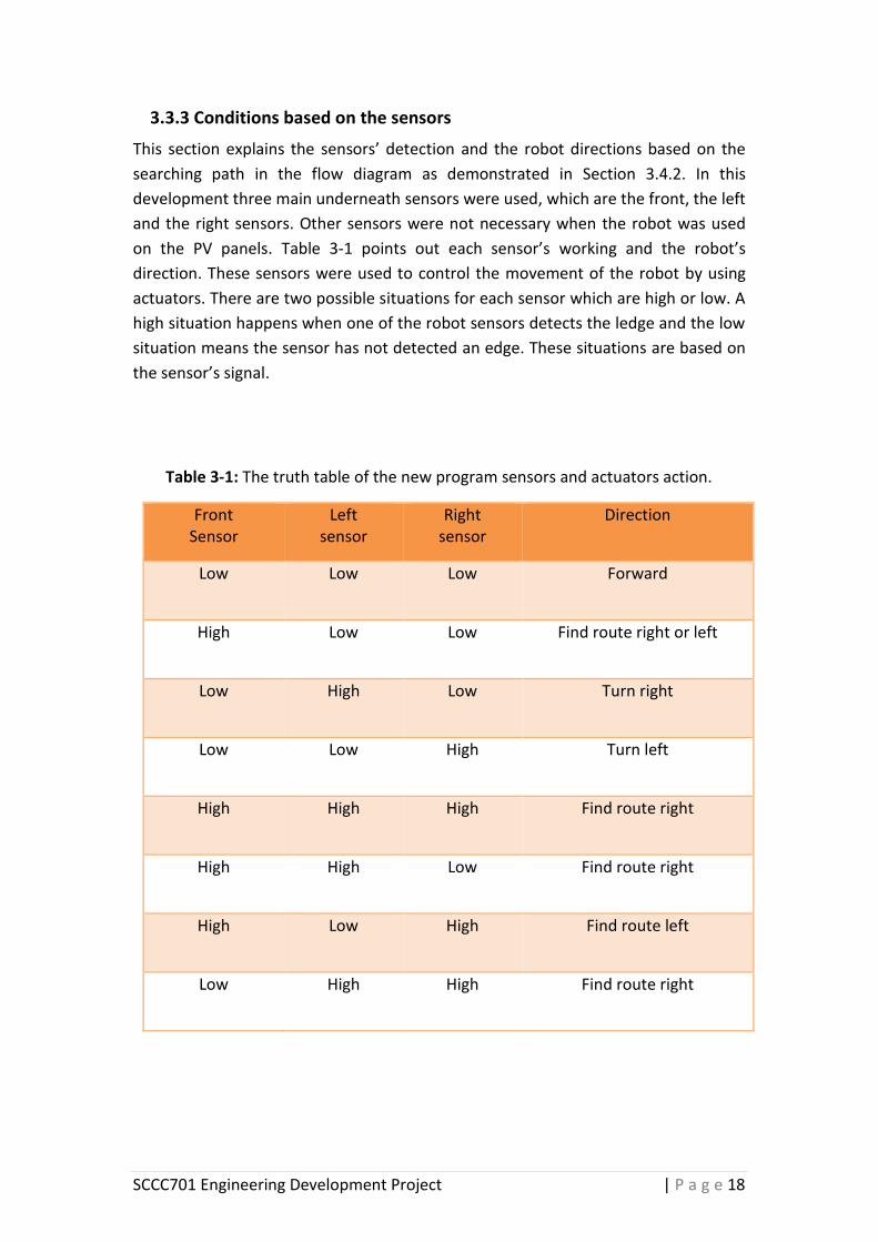
Table 3-1: The truth table of the new program sensors and actuators action.
Front Sensor
Left sensor
Right sensor
Direction
Low Low Low Forward
High Low Low Find route right or left
Low High Low Turn right
Low Low High Turn left
High High High Find route right
High High Low Find route right
High Low High Find route left
Low High High Find route right

SCCC701 Engineering Development Project | P a g e 19
The movement and rotation of the i7 cleaning robot was controlled by the right and
left wheels. A similar method was used to design the new software as shown in
Table 3-2. The new program was simulated on the Uno Arduino microcontroller.
Table 3-2: The cleaner robot’s motors control movement.
Robot Movement Left Motor Right Motor
Straight Straight Straight
Avoid the left edge Stop Reverse
Avoid the right edge Reverse Stop
Backward Reverse Reverse
Right-Rotating 180o Straight Stop
Left-Rotating 180o Stop Straight
This table demonstrated the direction movement of the robot when a sensor detects
an edge. There are six possible ways to change the robot’s direction.
First way; when all the sensors are low the robot will travel straight.
The second one; when the left sensor detects an edge on the left
side it will stop then turn to the right side four centimeters until the
left sensor goes to low.
The third situation; when the right edge is detected it will do the
same as the left sensor’s job when it detects the edge, but the
motor’s directions will be opposite.
The fourth situation is when the robot drives backward in three
circumstances. If the front sensor and the right sensor go high the
robot will stop, drive back 10cm, and change to the left direction,
and if all three sensors are high, the robot will stop and drive back
10cm, then find a route right. The last circumstance is if the front
sensor and the left sensor are high, the robot will stop and drive
back 10cm, then find a route right.
The fifth situation of the robot directions is when the robot rotates
180o to the right side. This happens when the robot reaches the top
ledge of the panel; it will stop and travel back 10cm, then rotates
180o as it drives down along the panel.
The last situation is when the robot rotates to the left side from the
bottom of the panel and drives up along the panel. The process of
the rotation is the same as for the right rotation.

SCCC701 Engineering Development Project | P a g e 20
3.3.4 Testing the operation of the new program
The new controlling program was tested on the Arduino µc with LED lights that
represented actuators, and three switches to represent the i7 cleaning robot’s
sensors as shown in Figure 3-8. The green lights represented the forward movement
of the robot; the red LED lights represented the backward movement of the robot,
and the orange LED light represented the brush actuator. The green and the red
LEDs on the right side of the prototype represented the right-motor of the i7
cleaning robot and the left side LED lights represented the left-motor. The three
sensors which are the front sensor, the left sensor and the right sensor are
controlling the robot movement on a set path and protect it from falling off the
panel. The circuit wiring diagram of the prototype is shown in Figure 3-9.
Figure 3-8: The prototype of the new program represented by LED lights and
controlled by Arduino microcontroller.
1. Represents the front sensor
2. Represents the left sensor
3. Represents the right sensor
4. Represents the right-motor forward
5. Represents the right-motor reverse
6. Represents the left-motor forward
7. Represents the left-motor reverse
8. Represents the brush’s motor
9. Represents the on and off switch
10. The Arduino microcontroller

SCCC701 Engineering Development Project | P a g e 21
The Arduino µc was used because it is useful in the robotics and the ease
of the installation. In addition, many useful examples can be downloaded
from the Arduino website.
Figure 3-9: Wiring diagram of the prototype.
D4
D5
D4
D6
D3
Left-Motor Right-Motor
Brush-Motor
Brush-MotorR-Motor-ReversL-Motor-ReversL-Motor-ForwardR-Motor-Forward
Front-SensorLeft-SensorRight-Sensor
+5V
D13
D11D12
Front-Proximity Sensor
Left-Proximity Sensor Right-Proximity Sensor
SCCC701 Engineering Development Project | P a g e 22
4. Result and discussion
In this section the results regarding the cleaning provided and the robot’s movement
on different angled boards are presented and discussed. Also, the result of testing
the new software is discussed. Some issues were found, and these problems will
affect the efficiency of the robot if it used on the PVs surface. The issues have been
divided into two main groups:
1- Mechanical construction analysis
2- Software development
4.1 The mechanical construction testing result
4.1.1 Testing the cleaning and the movement pattern of the robot on zero angle
The i7 cleaning robot proved a good cleaning method by removing all the tree leaves
and pollen to the main storage bin. Some of the powder was removed to the main
bin while the soft sticky powder was removed to the small bin; these processes were
carried out several times.
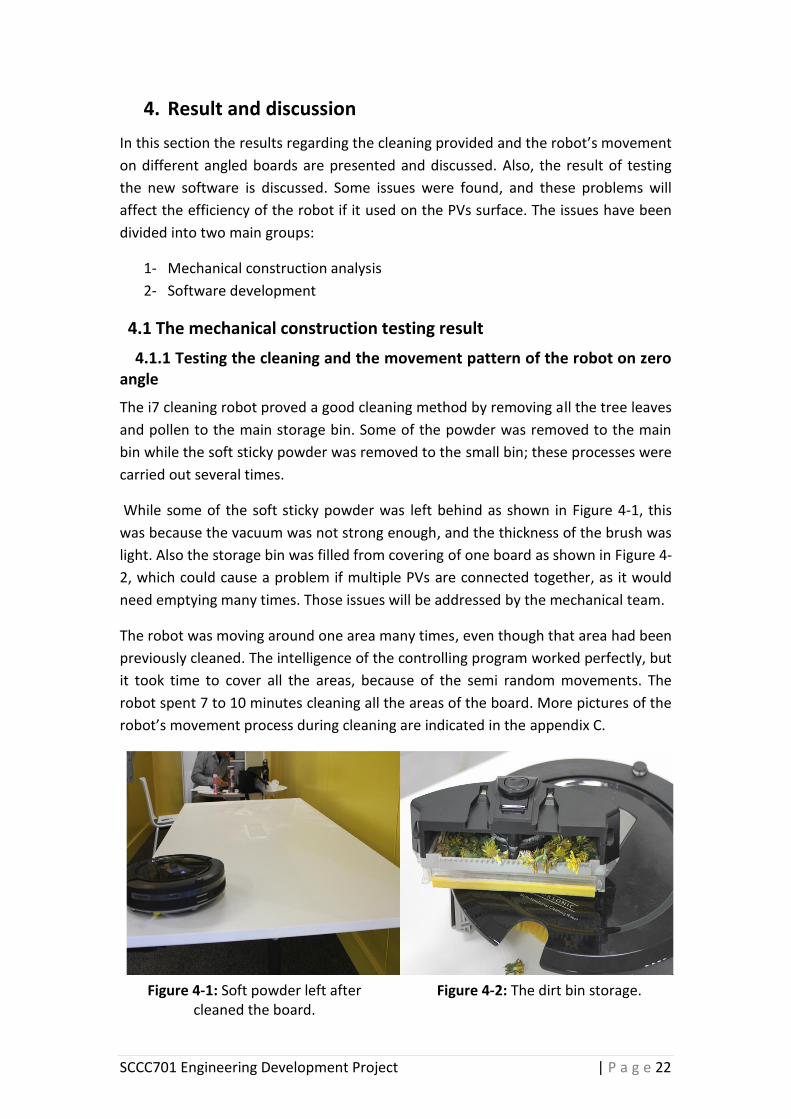
While some of the soft sticky powder was left behind as shown in Figure 4-1, this
was because the vacuum was not strong enough, and the thickness of the brush was
light. Also the storage bin was filled from covering of one board as shown in Figure 4-
2, which could cause a problem if multiple PVs are connected together, as it would
need emptying many times. Those issues will be addressed by the mechanical team.
The robot was moving around one area many times, even though that area had been
previously cleaned. The intelligence of the controlling program worked perfectly, but
it took time to cover all the areas, because of the semi random movements. The
robot spent 7 to 10 minutes cleaning all the areas of the board. More pictures of the
robot’s movement process during cleaning are indicated in the appendix C.
Figure 4-1: Soft powder left after cleaned the board.
Figure 4-2: The dirt bin storage.

SCCC701 Engineering Development Project | P a g e 23
4.1.2 The correct angle for the robot to be stable
On a board, the robot traveled up and down the smooth wooden board perfectly on
a 19.4 degree angle as shown in Figure 4-3. However the robot went a bit faster than
normal when it was going down the slope, but this did not affect the robot’s
movement, because the robot was still stable.
The robot slipped down when it was turned off at the top of the board because the
material of the wheels could not stop the robot from slipping.
Figure 4-3: The robot tested on 19.4 degree angle.

SCCC701 Engineering Development Project | P a g e 24
4.1.3 Testing the robot on a 45o angle
The robot was first tested on a 45 degree angle and it climbed well, however it
needed tip support on the front to give it more stability to avoid flipping, as shown in
Figure 4-4. If the robot does not have support in the front it will flip over, as shown
in Figure 4-5. Also, the movement of the robot was hard and more slippery.
When the robot traveled downward, it went faster than the normal speed because
of the weight of the robot pushing it down. If there was no raised edge on the panel
it would have fallen down, because there was not enough time for the edge
detecting sensor to sense this and then send a command to the microcontroller to
rotate the robot.
From this experiment it was found that the motors and the gearboxes that drove the
wheels were strong enough, and were capable of moving the robot on a 45 degree
angle.
Figure 4-5: The robot flipping over when it climbed on 45 degree angle.
Figure 4-4: Tip supported on the front of the robot.

SCCC701 Engineering Development Project | P a g e 25
4.1.4 Flipping angles
The robot started to flip when the angle was increased to 23 degrees, as shown in
Figure 4-6. The robot started to lose it stability at this point. The cause of flipping
was that the shape of the robot was designed to work on flat surface, not on angles.
4.1.5 Crossing between two boards
The maximum gap the robot can cross between two panels was 2cm as shown in
Figure 4-7; for gaps more than 2cm, the robot managed to detect the gap and then
changed direction to avoid falling down. Also, as the sizes of the wheels were small
the robot could not jump between two panels if the gap was bigger.
Figure 4-6: Starting flipping angle which is 23 degree angle.
Figure 4-7: The robot crossing between two boards.

SCCC701 Engineering Development Project | P a g e 26
4.1.6 Experiments to stop the robot flipping
Two experiments were carried out to find a solution to the robot flipping when it
worked at a angle or greater.
4.1.6.1 Support the robot by using different weights
The robot was tested again on a 45 degree angle supported with a 1 kg weight on
the front. It still started to flip over, even with the support of 1kg weight. The weight
was increased until the robot stopped flipping, and the support weight was 1.4 kg.
The robot climbed the board successfully, but without stability. Whereas, when
the robot traveled back down, it started to flip from the back and lost control as is
shown in Figure 4-8. This was because the movement was too fast.
4.1.6.2 Tested with a supported weight of 800 g
The robot was tested until a 30.4o angle and supported by a 800g weight on the top-
front. It climbed without flipping, but still needed some support to avoid slipping.
However, increasing the weight of the robot affected the battery life and the motor’s
life.
Figure 4-8: Extra weight added to the robot.

SCCC701 Engineering Development Project | P a g e 27
4.2 The prototype testing result
The result of the software development program, which was required to drive the
robot in a set path, was that it worked well. The time for the robot to clean a board
sized 1×2.20 meters in a set path was 2.42 minutes. However, the time taken in the
original program to cover same board was 7 to 10 minutes, which was an average of
8.50 minutes, because of the semi random movement. The time of the robot’s
battery life is 90 minutes when it is cleaning on a flat surface, but with the new
program it can clean 37 panels size 1×2.20 meters in 90 minutes, whereas in the
existing program it could only clean 11 panels of the same size in that time.
After thorough testing it was proven that the sensors worked effectively in all
aspects of controlling the robot, and prevented it from falling off the edge of the PV
panel. The full details of the testing process and the results are outlined below.
4.2.1 The forward path
The robot was moving along the left edge as shown in Figure 4-9 where there were
two possibilities of detecting edges. The first situation was when the robot started
moving up the panel and lost its direction on the left side. In this situation the left
sensor detected the edge then stopped, reversing the right motor 4cm each time
until the robot went back to the set path. The second situation was when the robot
reached the top edge; then the front sensor detected it, stopped and went backward
10cm, then rotated 180o before driving down as shown in Figure 4-10.
Top
L R
F
1 Go back
10cm
2 Rotate
180o
L R
F
Top
Reverse
Figure 4-10: The front edge detected and the robot rotated.
Figure 4-9: The left edge detected and the robot back to the path.

SCCC701 Engineering Development Project | P a g e 28
4.2.2 Rotation 180o right or left
The robot was rotating when the front sensor engaged. When the robot reached the
top edge it stopped, went backward 10cm, then rotated as shown in Figure 4-11.
Also the left rotation was the same as the right rotation process; however the robot
was rotated left when it reached the bottom of the panels as shown in Figure 4-12.
4.2.3 Right edge detected
The right sensor engaged whether the robot drove to the top or the bottom of the
panel. The right-side edge detection mode started the robot, then stopped it,
reversed the left motor 4cm each time until the robot went back to the set path as
shown in Figure 4-13.
Reverse
Top
L R
F
Figure 4-12: Rotation 180 degree to the left.
Figure 4-11: Rotation 180 degree to the right.
Figure 4-13: The right edge detected and the robot back to the path.

SCCC701 Engineering Development Project | P a g e 29
4.2.4 Ending the cleaning process
When the robot was on the top right of the panel, and rotating to the right side, the
front sensor and the right sensor engaged, and that meant that the robot had
reached the end (the right side of the panel) as shown in Figure 4-14. It then went
down to the original location, and then shifted into the idle mode until it restarted.
Whereas if the robot reached the end of the bottom of the panel during the
rotation, and if the front sensor and the left sensor engaged as shown in Figure 4-14
the robot went to the original location then shifted to the idle mode until the robot
restarted.
Rotating
left & F-L
sensors
engaged
Rotating
right & F-R
sensors
engaged
Top L
R
F
L
R F Starting
point
Figure 4-14: Detecting the End and back to the starting point.
SCCC701 Engineering Development Project | P a g e 30
5. Conclusion and recommendation
This project highlights the effect of dust, dirt, pollen, sea salt, and bird droppings on
the PV system’s efficiency. However, the development of the i7 cleaner robot can
help solve those problems. This development is divided into two parts; mechanical
(stability and cleaning mechanism) which will be developed by mechanical team next
semester, and the software development. The software development for the i7
cleaner robot has been done in this project. The cleaning time has been reduced
from eight to two minutes by setting a path for the robot on the surface of the PV
panels, instead of using the semi random movement method.
From this project learned about the field of robotics and designing programs using
Arduino software. Also learned how to lead and manage a project in the future.
The weaknesses of this project were the limited time and the fact that the
mechanical team work will not start until next semester.
Recommendations
In the future, the robot’s software can be developed to be smarter, such as
that when it cleans any PV panel surface, it will save the information about
ledges, size and its location.
Install the Arduino µc with the developed program into the robot after the
mechanic development.
Instead of increasing the robot weight to make it stable, changing the robot’s
shape with better cleaning mechanism is recommended.
Future development could be to connect the cleaner robot to Almalki Ali’s project,
which is monitoring PV panels wirelessly, and developing software connection to
give alarms and alerts. Further and useful information about the cleaner robot is
obtainable from
http://www.robotiklubi.ee/_media/kursused/roomba_sumo/failid/hacking_roomba.
SCCC701 Engineering Development Project | P a g e 31
6. Student Declaration
I have not copied any part of this report from any other person’s work, except as
correctly referenced. Collaboration: No other person has written any part of this
report for me.
Student Name: Nawaf Albaqawi
Student Signature: ________________________ (signature)
Hand-in Date 6 / 06 / 2014
Completion Date 5 / 06 / 2014
SCCC701 Engineering Development Project | P a g e 32
7. References
Adele. (2010, 8 5). The Effect of Snow on Solar Panels. Retrieved 10 2, 2013, from
One Block Off the Grid: http://1bog.org/blog/the-effect-of-snow-on-solar-
panels/
Adinoyi, M. J. (2013). Effect of dust accumulation on the power outputs of solar
photovoltaic modules. Retrieved 9 29, 2013, from sciencedirect:
http://www.sciencedirect.com/science/article/pii/S0960148113003078
Anderson, A. G. (2012). ROBOTIC DEVICE FOR CLEANING PHOTOVOLTAIC PANEL
ARRAYS. Retrieved 9 12, 2013, from Northeastern University:
http://www.coe.neu.edu/Research/robots/papers/CLAWAR09.pdf
Clean Energy Prize. (2013, 2 26). PV Cleaner. Retrieved 2 20, 2014, from Clean Energy
Prize: http://cep.mit.edu/wp-
content/uploads/2013/02/PV_Cleaner_Executive_Summary.pdf
Conduit, S. (2014). Solar Conduit. Retrieved 2 18, 2014, from solarconduit:
https://solarconduit.com/shop/checkout/cart/
Heliotex. (2013). HELIOTEX AUTOMATIC SOLAR PANEL CLEANING SYSTEM. Retrieved
9 14, 2013, from solarconduit: https://solarconduit.com/shop/sun/pv-
module-washing-systems/heliotex-automatic-solar-panel-cleaning-system-
50.html
Hill, C. (2013). The Effects of Temperature on Solar Panel Power Production.
Retrieved 10 1, 2013, from sfgate: http://homeguides.sfgate.com/effects-
temperature-solar-panel-power-production-79764.html
Jalbuena, K. R. (2010, 8 27). mars-inspired technology makes pv-panels-self cleaning.
Retrieved 9 14, 2013, from ecoseed.org/technology:
http://www.ecoseed.org/technology/13801-mars-inspired-technology-
makes-pv-panels-self-cleaning
Kasim, N. K. (2010). New Technique for Treatment of the dust accumulation from PV
solar panels surface. Iraqi Journal of Physics, 2010.
Siemens. (2013). The Dirt Must Disappear. Retrieved 9 14, 2013, from Siemens:
http://www.industry.siemens.com/topics/global/en/magazines/process-
news/sustainability/logo-controls-automatic-panel-
cleaning/pages/default.aspx
SCCC701 Engineering Development Project | P a g e 33
Sullivan, R. M. (2011). SHADOW EFFECTS ON A SERIES-PARALLEL ARRAY OF SOLAR
CELLS. Retrieved 10 1, 2013, from Nasa:
http://ntrs.nasa.gov/archive/nasa/casi.ntrs.nasa.gov/19650020213_1965020
213.pdf
Sustainble Electricity Association New Zealand. (2013, 11 7). SOLAR PV SURVEY
RESULTS RELEASED. Retrieved 2 25, 2014, from Sustainble Electricity
Association New Zealand: http://www.seanz.org.nz/News-Events/News/NZ-
Solar-PV-Surey-Results-released

SCCC701 Engineering Development Project | P a g e 34
8. Appendix
Appendix A The full codes of the developed software

SCCC701 Engineering Development Project | P a g e 35

SCCC701 Engineering Development Project | P a g e 36

SCCC701 Engineering Development Project | P a g e 37
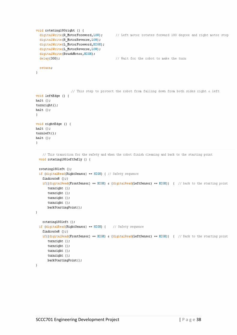
SCCC701 Engineering Development Project | P a g e 38

SCCC701 Engineering Development Project | P a g e 39

SCCC701 Engineering Development Project | P a g e 40

SCCC701 Engineering Development Project | P a g e 41

SCCC701 Engineering Development Project | P a g e 42
Appendix B The specification of the cleaner robot

SCCC701 Engineering Development Project | P a g e 43
Appendix C Photos of the robot’s movement process during cleaning
Related Documents