Proceedings of COBEM 2005 18th International Congress of Mechanical Engineering Copyright © 2005 by ABCM November 6-11, 2005, Ouro Preto, MG DEVELOPMENT OF AN AUTOMATIC INSPECTION EQUIPMENT BASED ON THE TOFD TECHNIQUE. Elineudo Pinho de Moura Programa de Mestrado em Engenharia e Ciências dos Materiais, Universidade Federal do Ceará, Campus do Pici, Centro de Tecnologia, Bloco 714, CEP.: 60455-760 e-mail: [email protected] Alex Araújo de Vasconcellos Engenharia Elétrica, Universidade Federal do Ceará. e-mail: [email protected] Abstract. Non-destructive testing (NDT) is a powerful tool employed to asses the integrity of parts, equipments and structures. NDT techniques are widely used for discontinuities detection and measurement. Each method has its advantages and drawbacks and the choice of the adequate NDT method relays on the desired application. Although the radiographic test is broadly applied for welded joints inspection, the ultrasound technique (UT) is replacing it for many applications. Among all of the UTs, the time of flight diffraction (TOFD) technique is becoming more and more attractive. Besides getting over the problems for the radiographic inspection in relation to detection and measurement of defects perpendicular to the surface of the sample, the TOFD technique allows one to perform automatic inspection and the acquisition of permanent inspection records. It is possible to perform faster inspections with high reliability and low false identification rates. The aim of this work was to develop an automatic inspection equipment based on the TOFD technique. This equipment is able to detect and measure defects in welded joints, metal sheets, pipes and other kinds of metallic structures so that the user influence on the data acquisition results is minimized and the test reliability is strongly increased. Its detection efficiency was determined based on the results acquired after inspections performed on test pieces in which well controlled defects were introduced. Keywords: NDT, Ultrasound, TOFD, Automation, Automatic Equipaments. 1. Introduction Non-destructive tests (NDT) are a powerful tool to warrant parts, equipments and structures integrity and so they are broadly used for detection and dimensioning of discontinuities in materials. There are many types of NDTs: penetrating fluids, magnetic particles, ultrasound, eddy currents, etc. (ASM Handbook, 1994, ASNT Handbook, 1991, ASNT Handbook, 1996). Each of them has its advantages and drawbacks depending on the material to be inspected, kind of discontinuity, material environment, etc. Thus, the choice of the most adequate method relays on the desired application. Although radiography (RT) is widely employed to detect and sizing up discontinuities in welded joints, it requires special safety procedures, time to develop the radiographic frame and its response is all about the discontinuity length which is not enough to assess risk caused by the defect. Then, ultrasound (UT) is becoming the best choice to replace RT because there is no harm for the operator and discontinuities can be well dimensioned. The arise of the time of flight diffraction technique (TOFD) (Silk, 1979, Silk, 1987) was a great progress for UT. TOFD has become more and more used because faster inspections can be performed with high reliability on the dimensioning and low false identification rates (Raad and Dijkstra, 1997, Verkooijen, 1995, Raad and Dijkstra, 1998). The ultrasound beam incides obliquely on the surface to be inspected so that RT drawbacks to detect and dimension discontinuities perpendicular to the surface part are overcome (Raad and Dijkstra, 1997, Verkooijen, 1995, Raad and Dijkstra, 1998). The automatic displacement of transducers combined with signal digitalization makes it possible to perform automatic inspections with permanent records. The present work was aimed to build an automatic inspection equipment based on TOFD. It is capable of detecting and dimensioning defects in welded joints, pipes and several other metallic structures. The expectation is to reduce operator influence and increase test reliability. The efficiency of the equipment was evaluated based on inspections on test pieces with well controlled defects.

Welcome message from author
This document is posted to help you gain knowledge. Please leave a comment to let me know what you think about it! Share it to your friends and learn new things together.
Transcript
Proceedings of COBEM 2005 18th International Congress of Mechanical EngineeringCopyright © 2005 by ABCM November 6-11, 2005, Ouro Preto, MG
DEVELOPMENT OF AN AUTOMATIC INSPECTION EQUIPMENTBASED ON THE TOFD TECHNIQUE.
Elineudo Pinho de MouraPrograma de Mestrado em Engenharia e Ciências dos Materiais, Universidade Federal do Ceará, Campus do Pici, Centro deTecnologia, Bloco 714, CEP.: 60455-760e-mail: [email protected]
Alex Araújo de VasconcellosEngenharia Elétrica, Universidade Federal do Ceará.e-mail: [email protected]
Abstract. Non-destructive testing (NDT) is a powerful tool employed to asses the integrity of parts, equipments andstructures. NDT techniques are widely used for discontinuities detection and measurement. Each method has itsadvantages and drawbacks and the choice of the adequate NDT method relays on the desired application.
Although the radiographic test is broadly applied for welded joints inspection, the ultrasound technique (UT) isreplacing it for many applications. Among all of the UTs, the time of flight diffraction (TOFD) technique is becomingmore and more attractive. Besides getting over the problems for the radiographic inspection in relation to detectionand measurement of defects perpendicular to the surface of the sample, the TOFD technique allows one to performautomatic inspection and the acquisition of permanent inspection records. It is possible to perform faster inspectionswith high reliability and low false identification rates.
The aim of this work was to develop an automatic inspection equipment based on the TOFD technique. Thisequipment is able to detect and measure defects in welded joints, metal sheets, pipes and other kinds of metallicstructures so that the user influence on the data acquisition results is minimized and the test reliability is stronglyincreased. Its detection efficiency was determined based on the results acquired after inspections performed on testpieces in which well controlled defects were introduced.
Keywords: NDT, Ultrasound, TOFD, Automation, Automatic Equipaments.
1. Introduction
Non-destructive tests (NDT) are a powerful tool to warrant parts, equipments and structures integrity and so they arebroadly used for detection and dimensioning of discontinuities in materials. There are many types of NDTs: penetratingfluids, magnetic particles, ultrasound, eddy currents, etc. (ASM Handbook, 1994, ASNT Handbook, 1991, ASNTHandbook, 1996). Each of them has its advantages and drawbacks depending on the material to be inspected, kind ofdiscontinuity, material environment, etc. Thus, the choice of the most adequate method relays on the desiredapplication.
Although radiography (RT) is widely employed to detect and sizing up discontinuities in welded joints, it requiresspecial safety procedures, time to develop the radiographic frame and its response is all about the discontinuity lengthwhich is not enough to assess risk caused by the defect. Then, ultrasound (UT) is becoming the best choice to replaceRT because there is no harm for the operator and discontinuities can be well dimensioned.
The arise of the time of flight diffraction technique (TOFD) (Silk, 1979, Silk, 1987) was a great progress for UT.TOFD has become more and more used because faster inspections can be performed with high reliability on thedimensioning and low false identification rates (Raad and Dijkstra, 1997, Verkooijen, 1995, Raad and Dijkstra, 1998).The ultrasound beam incides obliquely on the surface to be inspected so that RT drawbacks to detect and dimensiondiscontinuities perpendicular to the surface part are overcome (Raad and Dijkstra, 1997, Verkooijen, 1995, Raad andDijkstra, 1998). The automatic displacement of transducers combined with signal digitalization makes it possible toperform automatic inspections with permanent records.
The present work was aimed to build an automatic inspection equipment based on TOFD. It is capable of detectingand dimensioning defects in welded joints, pipes and several other metallic structures. The expectation is to reduceoperator influence and increase test reliability. The efficiency of the equipment was evaluated based on inspections ontest pieces with well controlled defects.
jokamoto
ABCM Symposium Series in Mechatronics - Vol. 2 - pp.105-112 Copyright © 2006 by ABCM
Proceedings of COBEM 2005 18th International Congress of Mechanical EngineeringCopyright © 2005 by ABCM November 6-11, 2005, Ouro Preto, MG
2. TOFD
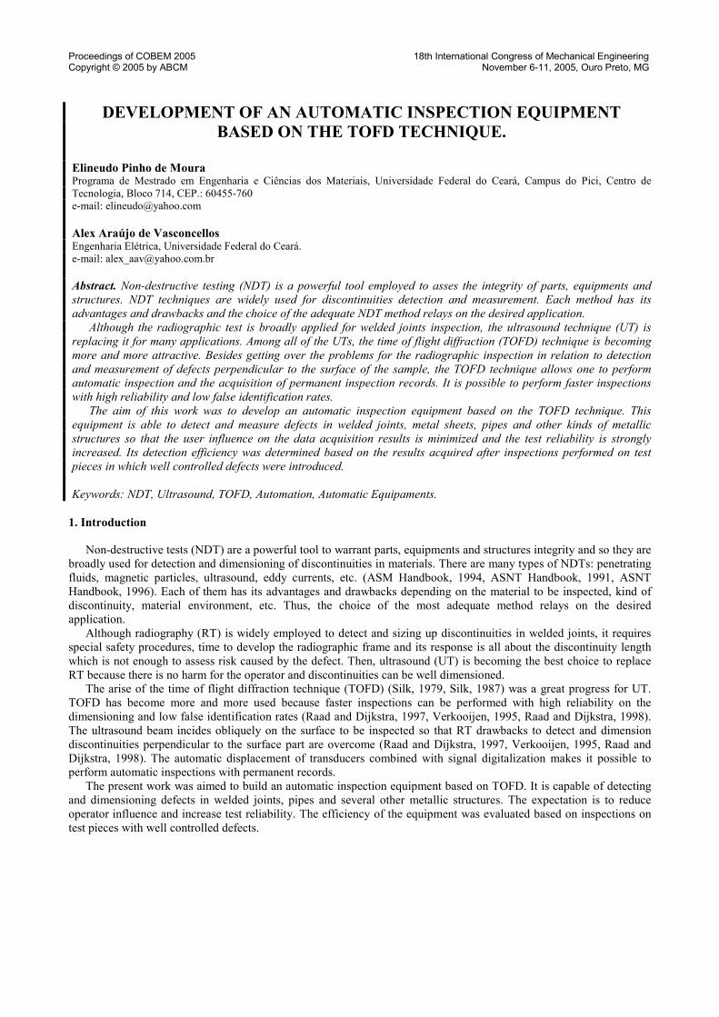
To dimension defects by TOFD, the position of the signals generated by their extremities, i.e., the time differencebetween them is recorded. Thus, TOFD is weakely affected by differences in signal amplitude. The traditional setup forTOFD is one emitting transducer and one receiving both aligned to the weld bead in order to cover the interest region(Fig. 1) (British Standard BS7706, 1993).
Figure 1 – Setup for TOFD: (1) Pulser, (2) Receiver, (a) Lateral wave, Diffracted wave from the upper (b) and lower (c)extremities of the defect and (d) Backwall echo.
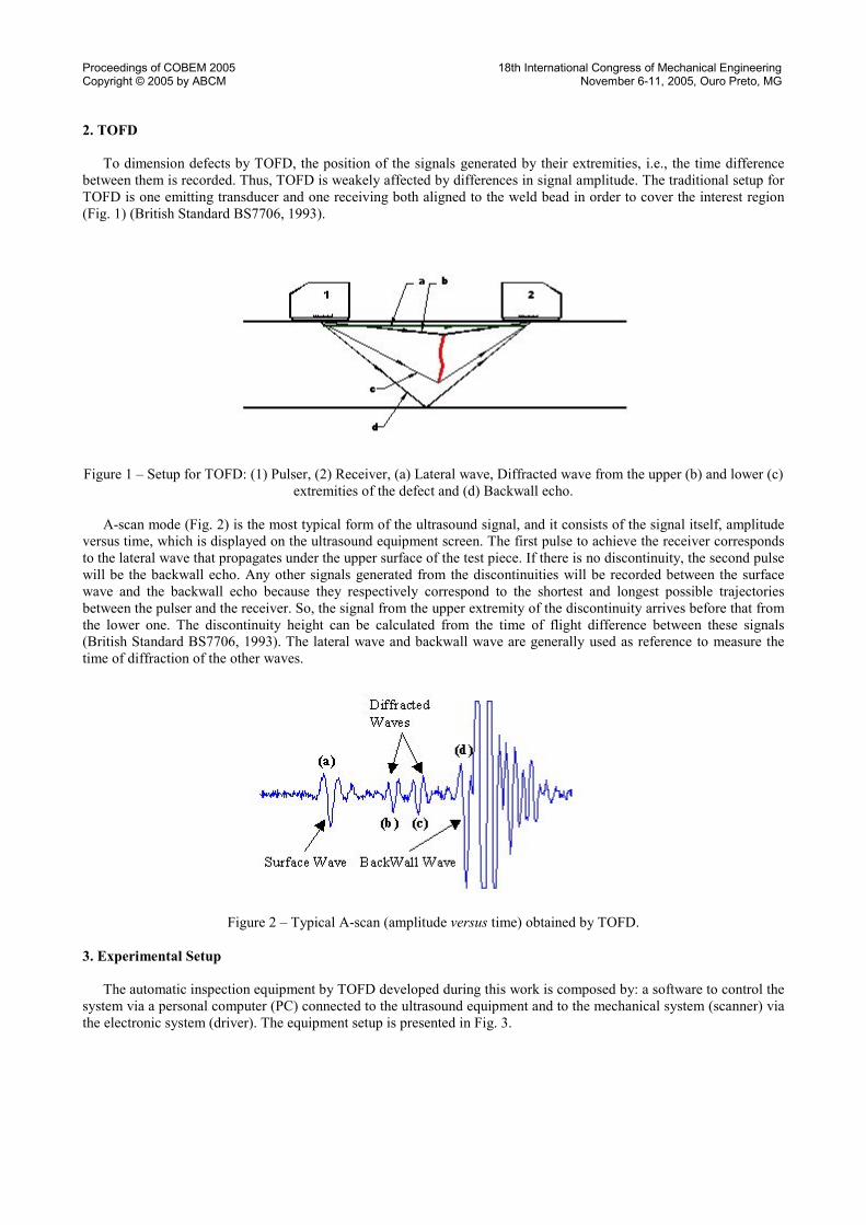
A-scan mode (Fig. 2) is the most typical form of the ultrasound signal, and it consists of the signal itself, amplitudeversus time, which is displayed on the ultrasound equipment screen. The first pulse to achieve the receiver correspondsto the lateral wave that propagates under the upper surface of the test piece. If there is no discontinuity, the second pulsewill be the backwall echo. Any other signals generated from the discontinuities will be recorded between the surfacewave and the backwall echo because they respectively correspond to the shortest and longest possible trajectoriesbetween the pulser and the receiver. So, the signal from the upper extremity of the discontinuity arrives before that fromthe lower one. The discontinuity height can be calculated from the time of flight difference between these signals(British Standard BS7706, 1993). The lateral wave and backwall wave are generally used as reference to measure thetime of diffraction of the other waves.
Figure 2 – Typical A-scan (amplitude versus time) obtained by TOFD.
3. Experimental Setup
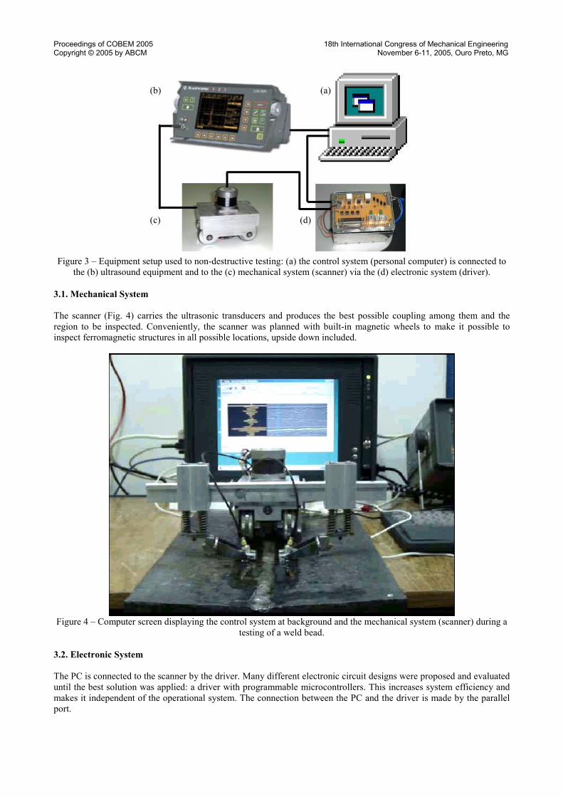
The automatic inspection equipment by TOFD developed during this work is composed by: a software to control thesystem via a personal computer (PC) connected to the ultrasound equipment and to the mechanical system (scanner) viathe electronic system (driver). The equipment setup is presented in Fig. 3.
Proceedings of COBEM 2005 18th International Congress of Mechanical EngineeringCopyright © 2005 by ABCM November 6-11, 2005, Ouro Preto, MG
Figure 3 – Equipment setup used to non-destructive testing: (a) the control system (personal computer) is connected tothe (b) ultrasound equipment and to the (c) mechanical system (scanner) via the (d) electronic system (driver).
3.1. Mechanical System
The scanner (Fig. 4) carries the ultrasonic transducers and produces the best possible coupling among them and theregion to be inspected. Conveniently, the scanner was planned with built-in magnetic wheels to make it possible toinspect ferromagnetic structures in all possible locations, upside down included.
Figure 4 – Computer screen displaying the control system at background and the mechanical system (scanner) during atesting of a weld bead.
3.2. Electronic System
The PC is connected to the scanner by the driver. Many different electronic circuit designs were proposed and evaluateduntil the best solution was applied: a driver with programmable microcontrollers. This increases system efficiency andmakes it independent of the operational system. The connection between the PC and the driver is made by the parallelport.
(a)(b)
(c) (d)
Proceedings of COBEM 2005 18th International Congress of Mechanical EngineeringCopyright © 2005 by ABCM November 6-11, 2005, Ouro Preto, MG
3.3. Control System
The control software manages the ultrasound on-line, real time data acquisition with scanner positioning. It was writtenin Borland C++ builder 6 and allows: (a) choice of communication ports with the driver and (b) with the ultrasoundequipment, which sends signals to the computer, besides (c) the choice of data transmission rate. With all theseparameters input, the user can displace transducers to setup initial inspection position or perform the inspection itself.
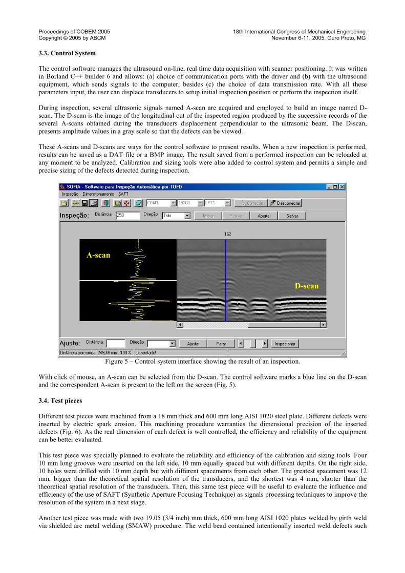
During inspection, several ultrasonic signals named A-scan are acquired and employed to build an image named D-scan. The D-scan is the image of the longitudinal cut of the inspected region produced by the successive records of theseveral A-scans obtained during the transducers displacement perpendicular to the ultrasonic beam. The D-scan,presents amplitude values in a gray scale so that the defects can be viewed.
These A-scans and D-scans are ways for the control software to present results. When a new inspection is performed,results can be saved as a DAT file or a BMP image. The result saved from a performed inspection can be reloaded atany moment to be analyzed. Calibration and sizing tools were also added to control system and permits a simple andprecise sizing of the defects detected during inspection.
Figure 5 – Control system interface showing the result of an inspection.
With click of mouse, an A-scan can be selected from the D-scan. The control software marks a blue line on the D-scanand the correspondent A-scan is present to the left on the screen (Fig. 5).
3.4. Test pieces
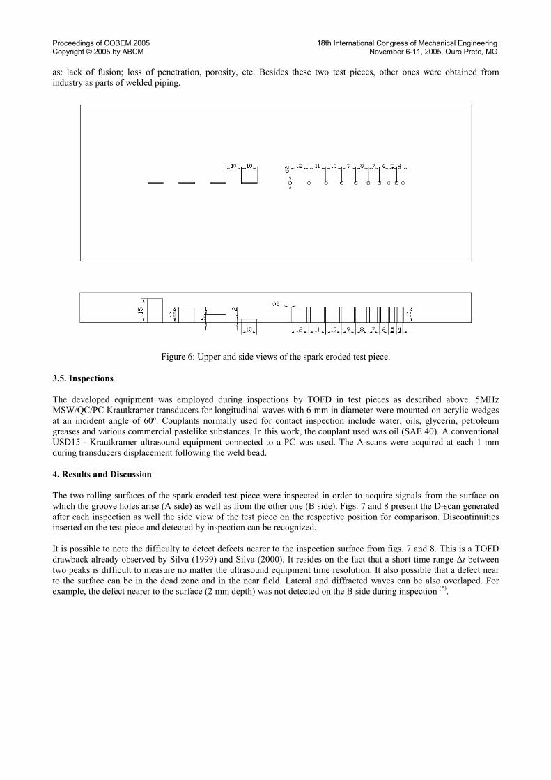
Different test pieces were machined from a 18 mm thick and 600 mm long AISI 1020 steel plate. Different defects wereinserted by electric spark erosion. This machining procedure warranties the dimensional precision of the inserteddefects (Fig. 6). As the real dimension of each defect is well controlled, the efficiency and reliability of the equipmentcan be better evaluated.
This test piece was specially planned to evaluate the reliability and efficiency of the calibration and sizing tools. Four10 mm long grooves were inserted on the left side, 10 mm equally spaced but with different depths. On the right side,10 holes were drilled with 10 mm depth but with different spacements from each other. The greatest spacement was 12mm, bigger than the theoretical spatial resolution of the transducers, and the shortest was 4 mm, shorter than thetheoretical spatial resolution of the transducers. Then, this same test piece will be useful to evaluate the influence andefficiency of the use of SAFT (Synthetic Aperture Focusing Technique) as signals processing techniques to improve theresolution of the system in a next stage.
Another test piece was made with two 19.05 (3/4 inch) mm thick, 600 mm long AISI 1020 plates welded by girth weldvia shielded arc metal welding (SMAW) procedure. The weld bead contained intentionally inserted weld defects such
D-scan
A-scan
Proceedings of COBEM 2005 18th International Congress of Mechanical EngineeringCopyright © 2005 by ABCM November 6-11, 2005, Ouro Preto, MG
as: lack of fusion; loss of penetration, porosity, etc. Besides these two test pieces, other ones were obtained fromindustry as parts of welded piping.
Figure 6: Upper and side views of the spark eroded test piece.
3.5. Inspections
The developed equipment was employed during inspections by TOFD in test pieces as described above. 5MHzMSW/QC/PC Krautkramer transducers for longitudinal waves with 6 mm in diameter were mounted on acrylic wedgesat an incident angle of 60º. Couplants normally used for contact inspection include water, oils, glycerin, petroleumgreases and various commercial pastelike substances. In this work, the couplant used was oil (SAE 40). A conventionalUSD15 - Krautkramer ultrasound equipment connected to a PC was used. The A-scans were acquired at each 1 mmduring transducers displacement following the weld bead.
4. Results and Discussion
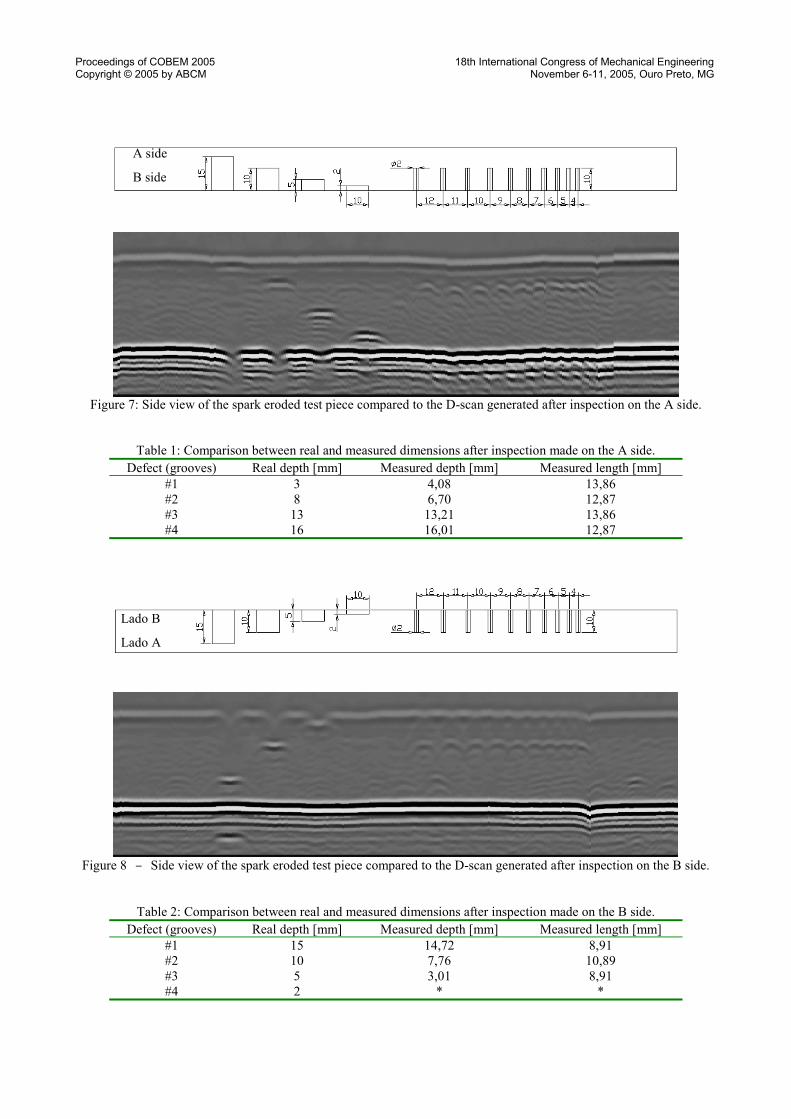
The two rolling surfaces of the spark eroded test piece were inspected in order to acquire signals from the surface onwhich the groove holes arise (A side) as well as from the other one (B side). Figs. 7 and 8 present the D-scan generatedafter each inspection as well the side view of the test piece on the respective position for comparison. Discontinuitiesinserted on the test piece and detected by inspection can be recognized.
It is possible to note the difficulty to detect defects nearer to the inspection surface from figs. 7 and 8. This is a TOFDdrawback already observed by Silva (1999) and Silva (2000). It resides on the fact that a short time range Δt betweentwo peaks is difficult to measure no matter the ultrasound equipment time resolution. It also possible that a defect nearto the surface can be in the dead zone and in the near field. Lateral and diffracted waves can be also overlaped. Forexample, the defect nearer to the surface (2 mm depth) was not detected on the B side during inspection (*).
Proceedings of COBEM 2005 18th International Congress of Mechanical EngineeringCopyright © 2005 by ABCM November 6-11, 2005, Ouro Preto, MG
Figure 7: Side view of the spark eroded test piece compared to the D-scan generated after inspection on the A side.
Table 1: Comparison between real and measured dimensions after inspection made on the A side.Defect (grooves) Real depth [mm] Measured depth [mm] Measured length [mm]
#1 3 4,08 13,86#2 8 6,70 12,87#3 13 13,21 13,86#4 16 16,01 12,87
Figure 8 – Side view of the spark eroded test piece compared to the D-scan generated after inspection on the B side.
Table 2: Comparison between real and measured dimensions after inspection made on the B side.Defect (grooves) Real depth [mm] Measured depth [mm] Measured length [mm]
#1 15 14,72 8,91#2 10 7,76 10,89#3 5 3,01 8,91#4 2 * *
A side
B side
Lado B
Lado A
Proceedings of COBEM 2005 18th International Congress of Mechanical EngineeringCopyright © 2005 by ABCM November 6-11, 2005, Ouro Preto, MG
It can be easily seen on the D-scan (Figs. 7 and 8) that the two more spaced holes can be distinguished. It is also notedthat it is not easy to resolve the next defects as they become less spaced. Then, this test piece will be also useful toevaluate the use of SAFT to improve the resolution of the system in a next stage.
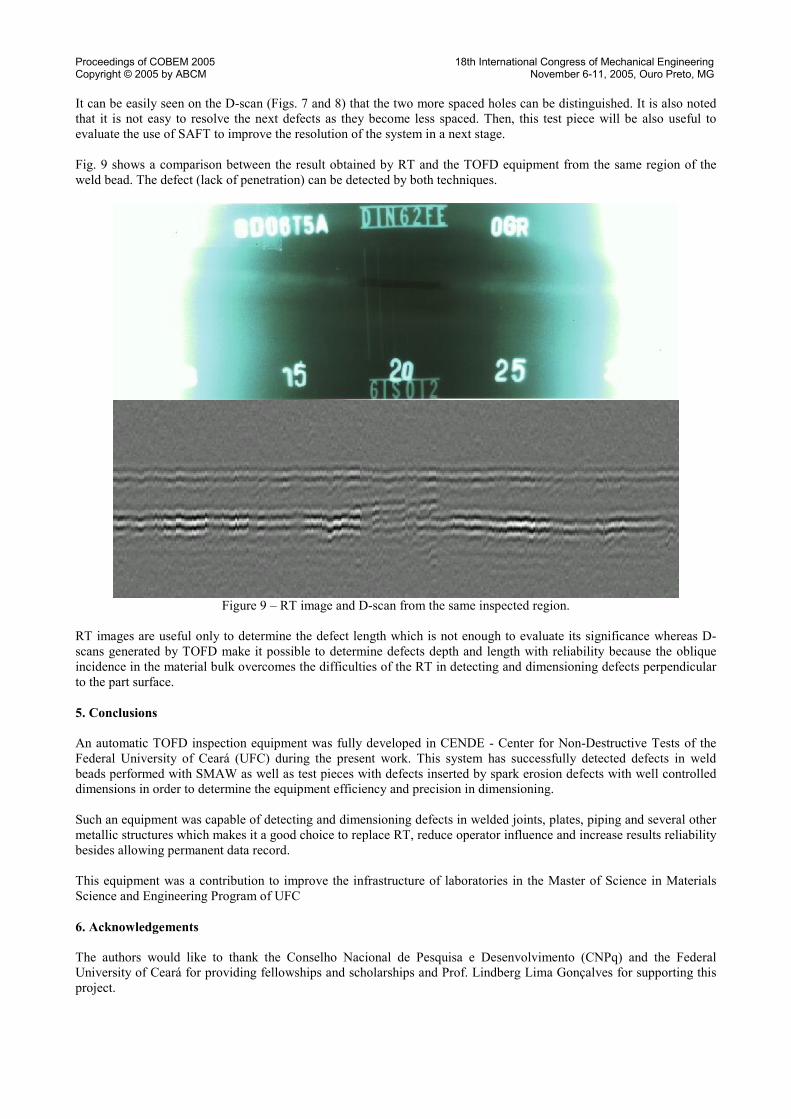
Fig. 9 shows a comparison between the result obtained by RT and the TOFD equipment from the same region of theweld bead. The defect (lack of penetration) can be detected by both techniques.
Figure 9 – RT image and D-scan from the same inspected region.
RT images are useful only to determine the defect length which is not enough to evaluate its significance whereas D-scans generated by TOFD make it possible to determine defects depth and length with reliability because the obliqueincidence in the material bulk overcomes the difficulties of the RT in detecting and dimensioning defects perpendicularto the part surface.
5. Conclusions
An automatic TOFD inspection equipment was fully developed in CENDE - Center for Non-Destructive Tests of theFederal University of Ceará (UFC) during the present work. This system has successfully detected defects in weldbeads performed with SMAW as well as test pieces with defects inserted by spark erosion defects with well controlleddimensions in order to determine the equipment efficiency and precision in dimensioning.
Such an equipment was capable of detecting and dimensioning defects in welded joints, plates, piping and several othermetallic structures which makes it a good choice to replace RT, reduce operator influence and increase results reliabilitybesides allowing permanent data record.
This equipment was a contribution to improve the infrastructure of laboratories in the Master of Science in MaterialsScience and Engineering Program of UFC
6. Acknowledgements
The authors would like to thank the Conselho Nacional de Pesquisa e Desenvolvimento (CNPq) and the FederalUniversity of Ceará for providing fellowships and scholarships and Prof. Lindberg Lima Gonçalves for supporting thisproject.
Proceedings of COBEM 2005 18th International Congress of Mechanical EngineeringCopyright © 2005 by ABCM November 6-11, 2005, Ouro Preto, MG
7. References
ASM Handbook - "Nondestructive Evaluation and Quality Control", 9th ed., Vol. 17, (The Materials InformationSociety, New York, 1994).
ASNT Handbook - "Ultrasonic Testing", editor P. McIntire, Vol. 7, (ASNT, New York, 1991).ASNT Handbook - Nondestructive Testing Overview, editors P. O. Moore and P. McIntire, Vol. 10, (ASNT, New
York, 1996);British Standard BS7706, Guide to Calibration and Setting-up of the Ultrasonic Time of Flight Diffraction (TOFD)
Technique for the Detection, Location and Sizing of Flaws, 1993.Raad, J.A., Dijkstra, F.H, "Mechanized Ultrasonic testing on Girth Welds During Pipeline Constructions", Materials
Evaluation, 55 (8), pp 890-895, Auguste 1997.Raad, J. A., Dijkstra, F. H., "Mechanised UT on Girth Welds During Pipeline Construction - a Mature Alternative to
Radiography", Insight 40 (6), pp. 435-438, (1998).Silk. M.G., "Transfer of Ultrasonic Energy in the Diffraction Technique for Crack Sizing", Ultrasonics 17 (3), pp
113-121, (1979)Silk, M.G., "Changes in Ultrasonic Defect Location and Sizing", NDT International 20 (1), pp 9-14, Feb (1987)Silva, I. C., "Avaliação da Técnica do Tempo de Percurso da Onda Difratada no Dimensionamento de
Descontinuidades", MSc. dissertation, Universidade Federal do Rio de Janeiro, COPPE/UFRJ, Rio de Janeiro, março1999.
Silva, S.G., "Técnica Ultra-Sônica do Tempo de Percurso da Onda Difratada na Detecção e Dimensionamento deDescontinuidades em Cordões de Solda de Aço", MSc. dissertation, Universidade Federal do Rio de Janeiro,COPPE/UFRJ, Rio de Janeiro, dezembro 2000.
Verkooijen, J., "TOFD Used to Replace Radiography", Insight 37 (6), pp. 433-435, Jun 1995.
8. Responsibility notice
The authors are the only responsibles for the printed material included in this paper.
Related Documents