180 QR of RTRI, Vol. 53, No. 3, Aug. 2012 Masanori HANSAKA, Dr.Eng. Senior Researcher, Laboratory Head, Daigo SATO Researcher, Development of a Wind Load Reduction Soundproof System Vibration-Isolating Materials Laboratory, Material Technology Division Shogo MAMADA Assistant Senior Researcher, Vibration-Isolating Materials Laboratory, Material Technology Division Nozomu TANIGUCHI, Dr.Eng. Senior Researcher, Steel & Hybrid Structure Laboratory, Structure Technology Division It is generally difficult to install extremely high soundproof walls without drastic rein- forcement of the viaduct because the higher the wall, the greater the wind load and moment. A new type of soundproof system was therefore developed. The proposed system comprises a clear soundproof plate and supporting frames. The top of soundproof plate is supported by a rotary axis and all or a part of the other three sides of the plate are fixed by magnetic attrac- tive forces and offers high soundproof performance in ordinary conditions. When the wind load exceeds the safety limit for the viaduct, the plate opens and the appropriate wind load is released. A load test and wind tunnel test were conducted and the wind load reduction mech- anism of the developed system was verified. Keywords: railway noise, viaduct, soundproof wall, sound insulation, wind load 1. Introduction Soundproof walls have been added to concrete viaducts and other railway structures to abate railway noise. In recent years, demand has appeared for extremely higher soundproof constructions to improve noise abatement per- formance around railway tracks for the needs attendant on a speed up of train and increase of tall buildings near railway lines. Higher walls installed on viaducts, however, lead to higher wind loads and moments. As such, it is al- most impossible to install extremely high soundproof con- structions without concomitant reinforcement of the via- duct. A new soundproof system was therefore proposed [1]. It is composed of a soundproof plate and a set of frames. The top side of the soundproof plate is supported by a ro- tary axis, and all or a part of the other three sides are fixed by magnetic attractive forces. The plate usually remains closed and will open in case of strong wind exceeding a load of 1.5kPa, under which the safety for the viaduct is kept. In order to verify the wind load reduction mechanism of the new soundproof system, load and wind tunnel tests were performed. 2. Specifications for the developed soundproof sys- tem 2.1 Specifications The specifications to be satisfied by the new system were identified as follows; (1) High sound proofing performance in ordinary con- ditions. (2) High wind abatement performance in strong winds. (3) Adaptable for installation on existing soundproof standard-sized walls 3m high, 3m wide and 0.2m maximum depth. (4) Easy maintenance (as a standard maintenance guide, inspections are expected to be carried out every two years). (1) and (2) are essential specifications for the sound- proof system; each specific value is given in the next chap- ter, (3) and (4) are set to meet the demands of railway com- panies. Regarding (3), the width was set on the premise that soundproof plates would generally be affixed to exist- ing soundproof walls between pillars, which are installed at approximately every 3m along the railway. 2.2 Sound abatement performance The sound reducing performance of the system can be estimated from the sound transmission model shown in Fig.1 because the sound reduction mechanism is similar to that of the soundproof plate installed on the existing soundproof wall. The path along which the sound transmits over an existing 2m high soundproof wall above rail level is defined as path A. The path over a 3m high soundproof plate on the existing soundproof wall is defined as path B. L pa , the sound pressure level along path A is equal to the sum of L pb (the sound pressure level along path B), and L pc (the sound pressure level transmitted through the part of soundproof plate on the soundproof wall). Consequently, L pa is given as follows; 10 10 10 10 10 10 L L L pa pb pc = + (1) PAPER

Welcome message from author
This document is posted to help you gain knowledge. Please leave a comment to let me know what you think about it! Share it to your friends and learn new things together.
Transcript

180 QR of RTRI, Vol. 53, No. 3, Aug. 2012
Masanori HANSAKA, Dr.Eng.Senior Researcher, Laboratory Head,
Daigo SATOResearcher,
Development of a Wind Load Reduction Soundproof System
Vibration-Isolating Materials Laboratory, Material Technology Division
Shogo MAMADAAssistant Senior Researcher,
Vibration-Isolating Materials Laboratory, Material Technology Division
Nozomu TANIGUCHI, Dr.Eng. Senior Researcher,
Steel & Hybrid Structure Laboratory, Structure Technology Division
It is generally difficult to install extremely high soundproof walls without drastic rein-forcement of the viaduct because the higher the wall, the greater the wind load and moment. A new type of soundproof system was therefore developed. The proposed system comprises a clear soundproof plate and supporting frames. The top of soundproof plate is supported by a rotary axis and all or a part of the other three sides of the plate are fixed by magnetic attrac-tive forces and offers high soundproof performance in ordinary conditions. When the wind load exceeds the safety limit for the viaduct, the plate opens and the appropriate wind load is released. A load test and wind tunnel test were conducted and the wind load reduction mech-anism of the developed system was verified.
Keywords: railway noise, viaduct, soundproof wall, sound insulation, wind load
1. Introduction
Soundproof walls have been added to concrete viaducts and other railway structures to abate railway noise. In recent years, demand has appeared for extremely higher soundproof constructions to improve noise abatement per-formance around railway tracks for the needs attendant on a speed up of train and increase of tall buildings near railway lines. Higher walls installed on viaducts, however, lead to higher wind loads and moments. As such, it is al-most impossible to install extremely high soundproof con-structions without concomitant reinforcement of the via-duct. A new soundproof system was therefore proposed [1]. It is composed of a soundproof plate and a set of frames. The top side of the soundproof plate is supported by a ro-tary axis, and all or a part of the other three sides are fixed by magnetic attractive forces. The plate usually remains closed and will open in case of strong wind exceeding a load of 1.5kPa, under which the safety for the viaduct is kept. In order to verify the wind load reduction mechanism of the new soundproof system, load and wind tunnel tests were performed.
2. Specifications for the developed soundproof sys-tem
2.1 Specifications
The specifications to be satisfied by the new system were identified as follows;
(1) High sound proofing performance in ordinary con-ditions.
(2) High wind abatement performance in strong winds.
(3) Adaptable for installation on existing soundproof standard-sized walls 3m high, 3m wide and 0.2m maximum depth.
(4) Easy maintenance (as a standard maintenance guide, inspections are expected to be carried out every two years).
(1) and (2) are essential specifications for the sound-proof system; each specific value is given in the next chap-ter, (3) and (4) are set to meet the demands of railway com-panies. Regarding (3), the width was set on the premise that soundproof plates would generally be affixed to exist-ing soundproof walls between pillars, which are installed at approximately every 3m along the railway.
2.2 Sound abatement performance
The sound reducing performance of the system can be estimated from the sound transmission model shown in Fig.1 because the sound reduction mechanism is similar to that of the soundproof plate installed on the existing soundproof wall. The path along which the sound transmits over an existing 2m high soundproof wall above rail level is defined as path A. The path over a 3m high soundproof plate on the existing soundproof wall is defined as path B. Lpa, the sound pressure level along path A is equal to the sum of Lpb (the sound pressure level along path B), and Lpc
(the sound pressure level transmitted through the part of soundproof plate on the soundproof wall). Consequently, Lpa is given as follows;
10 10 1010 10 10L L Lpa pb pc= + (1)
PAPER

181QR of RTRI, Vol. 53, No. 3, Aug. 2012
Now, assuming that acoustic transmission loss of the soundproof plate on the soundproof wall is TL, (1) is modi-fied as follows to obtain (2).
10 10 1010 10 10L L L TLp pb pc= + −( ) (2)
The sound reduction obtained (= DL) by installing the soundproof plate on the existing soundproof wall is given by
∆L L Lpa p= − (3)
It is proposed that the method of prediction for the sound pressure level transmitted along railway viaduct by reference [2], La and Lb can be calculated by this method. Then, DL is calculated by the (1)-(3). Considering sound conditions by viaducts constructed along Shinkansen lines and the reported results of soundproof wall installations [2], DL is expected to be over 5dB at the observation point where the distance from railway viaduct center is 25m at 1.2m from the ground.
As the result of simulation of the DL by the method above mentioned with changing TL, the relationship be-tween TL and DL is given as Fig. 2. In this estimation, train velocity was set at 360km/h in anticipation of higher run-ning speeds in the future. It is reasonable to assume that TL should be 15 ~ 16dB in order to ensure that DL is over 5dB in Fig. 2. Based on this estimation, the performance of acoustic transmission loss was set to 16dB (as the all pass value).
Fig. 1 Schematic model of sound transmission around the railway viaduct
Fig. 2 Relationship between TL and DL
2m Sound sourcePath B
Path A
Observation point
Existing soundproof wall
Soundproof plate
3m
0
1
2
3
4
5
6
0 5 10 15 20 25
L (d
B)
TL (dB)
∆
2.3 Wind load reduction performance
The strength of viaduct and soundproof wall construct-ed on it was inspected assuming that a unit soundproof system panel 3m high and 3m wide would be installed on the existing wall of 2m high above rail level along the railway. After applying the new 3m soundproof panels to existing soundproof walls on the viaduct, in order to main-tain the safety of the whole structure wind load must be kept under 1.5kPa even when the load of the blowing wind is 3kPa, which is the maximum admissible value in the design of railway structures. Based on this estimation, the wind abatement performance of the soundproof system was determined as the capacity to reduce wind load from 3kPa to 1.5kPa (50% reduction).
3. Design for the new sound and wind load reducing structure
3.1 Investigation of existing equipment options
To ensure the soundproof system could meet the above-mentioned specifications, firstly, existing equipment op-tions were investigated. Among the equipment identified as possible candidates were silencers, which have a ven-tilation function. Louvred type silencers which comprises many thin blades at identical pitch offering lighting or ven-tilation, is a representative type of silencer, used for venti-lation. Louvred type silencers for sound reduction and wind load reduction have already been studied [3]. However, for these types of silencers to improve wind load reduction per-formance the blade pitch would need to be increased at the expense of sound abatement performance, and vice versa. Therefore, simultaneous improvement in sound and wind load abatement performance is incompatible with ventila-tor type silencers. In reference [3], the acoustic transmis-sion loss of a louvred type silencer 0.22m thick offering 40% reduction in wind load is less than 10dB.
A mechanical system was then developed compris-ing a mechanically controlled soundproof plate which remained closed under ordinary conditions and opened in strong winds. This system has the design flexibility to have both high wind load reduction and sound reduction performance. However, the mechanical system with its many components, complex structure and mechanics and large size, does not satisfy the specification to be less than 200mm thick. More frequent maintenance is also required at shorter periods than the specified two years.
3.2 New structure design for sound and wind load reduction
Since none of the existing equipment was found to meet the soundproof system specifications, a new struc-ture and mechanism was developed. The resulting new structure design is shown in Fig. 3. It is composed of a soundproof plate and supporting frame. The top side of the soundproof plate is supported by a rotary axis, and all or a part of the other three sides are fixed by magnetic forces. 1mm thick steel plates are attached on right, left and bottom side of the soundproof plate. Some permanent

182 QR of RTRI, Vol. 53, No. 3, Aug. 2012
magnets are attached on all or a part of the three sides excluding the top side of the frame fixing the soundproof plate by magnetic force. The soundproof plate usually re-mains closed and opens in case of strong winds whose load exceeds 1.5kPa. The soundproof plate is made of a clear 8mm thick polycarbonate plate to ensure that the scenery can still be seen from the train window and to prevent cut-ting off sunlight to residents in the vicinity of the railway line. This system satisfies the specification that thickness should be less than 200mm. And because this system is composed only of simple members which don’t need extra works for maintenance, it presumably meets the specifica-tion to be easy maintenance.
In addition when the soundproof plate in the system opens, trains will be stopped because of the strong winds. The soundproof plate will remain closed, however, during train operations since the wind load caused by a passing train is presumed to be below 1kPa [4].
4. Verification of wind load reduction performance by load testing
4.1 Estimation of a concentrated load equilibrated with a wind load
With a wind load applied uniformly on the soundproof plate the soundproof plate will open when the wind load
Fig. 3 Structure and movement of soundproof system
(a) Wind load is under 1.5kPa (b) Wind load exceeding 1.5kPa
Soundproof plate
Frame Steel plate
Magnet Rotary axis
moment around the rotary axis exceeds the magnetic at-tractive forces on all or a part of three sides of the sound-proof plate. Since the soundproof plate is made of a rigid uniform material,a concentrated load equilibrated with a wind load applied to the soundproof plate can be estimated. This approach facilitates the design and serves to verify the system’s dynamics. Assuming that both a uniform wind load and a concentrated load are exerted vertically onto the soundproof plate, that since the soundproof plate is made of a rigid uniform material, the displacement of the plate around the axis is uniform, the equilibrium model in Fig.4 is formulated. Figure 4 (a) shows a wind load model and Fig. 4 (b) shows a concentrated load model. In these mod-els, the upper side has a rotary axis and the bottom side of the soundproof plate is fixed by magnetic attractive force. In the experiment described later, additional trials adding magnetic force to the right and left sides of the soundproof plate were also conducted and verified. Nonetheless, this analysis only focuses on the case when the magnetic attrac-tive force is applied on the bottom side given that magnetic attractive force applied on the bottom side is dominant when the soundproof plate just begins to open.
Firstly, the uniform wind load shown in Fig. 4 (a) was analyzed. When the soundproof plate remains closed, and reaction force is RA (N) on the rotary axis and RB (N) on the bottom side,the equation for the load equilibrium in the normal direction is given as follows:
R R pblA B= = 12 (4)
Fig. 4 Equilibrium model when the soundproof plate remains closed
(a) Wind load model
RA
RB
l
b
Wind load
Concentrated load
x
RB
RA
(b) Concentrated load model
183QR of RTRI, Vol. 53, No. 3, Aug. 2012
Where p(Pa) is the wind load applied vertically onto the soundproof plate, b(m) is the width and l(m) is the height of the soundproof plate.
Then, the equation of a moment of wind load equili-brated with a moment of RB is given as follows:
M R pblp Bl= = 12
2 (5)
where Mp (N・m) is the wind load moment.In Fig.4 (b), a concentrated load moment applied to the
center of the soundproof plate across its width and at x (m) distance from the rotary axis is given by F×x, and as is equilibrated with the moment Mp,giving (6).
FMx
pblx
p= =2
2 (6)
where F (N) is the concentrated load.The limit value which is defined as a concentrated load
equilibrated with uniform wind load of 1.5kPa is calculated to be about 69.8N with (6), where p is set as 1.5kPa, b is as 0.3m, l is as 0.3m and x is as 0.29m.
4.2 Load test
4.2.1 Test method
To verify the mechanics of the soundproof plate in this system, a load test was performed. In the load test, the structure of the specimen was based on the design men-tioned in Chapter 3. The specimen soundproof plate was made of a phenolic resin plate approximately 5mm thick, 0.3m high and 0.3m wide. Several neodymium magnets of about 17×12×5mm in size with a magnetic attractive force of about 37N in the normal direction, were attached on all or a part of the sides except for the top of the frame. Ten magnets could be attached to one side of frame, allow-ing arbitrary adjustment of the magnetic attractive force by changing the number of magnets. Figure 5 provides a view of a load test. A concentrated load was applied by the test bench to the horizontal center 0.29m away from the rotary axis of the soundproof plate. Results of measure-ments of gusts of wind [5], indicated that the load incre-ment speed in the case of gusts could be assumed to be
about 15N/s. The test bench load application speed , i.e. the crosshead speed on the test bench was set to approximately 500mm/min in order to reproduce a concentrated load ap-plication velocity to the soundproof plate of approximately 15N/s.
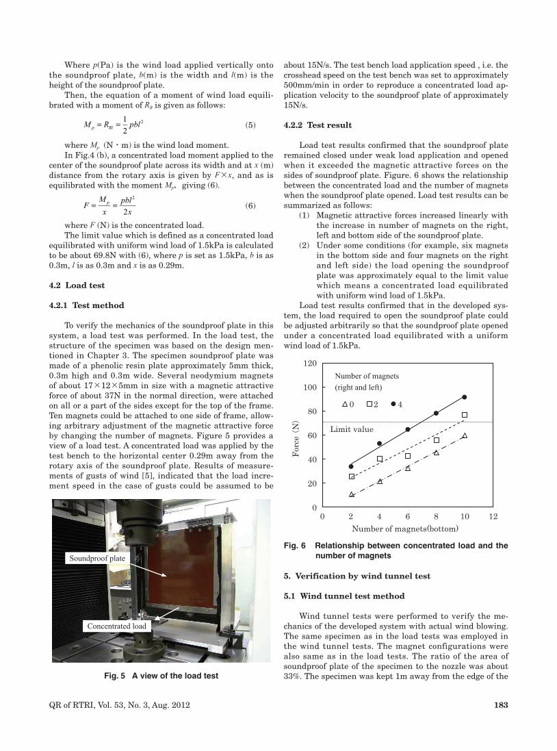
4.2.2 Test result
Load test results confirmed that the soundproof plate remained closed under weak load application and opened when it exceeded the magnetic attractive forces on the sides of soundproof plate. Figure. 6 shows the relationship between the concentrated load and the number of magnets when the soundproof plate opened. Load test results can be summarized as follows:
(1) Magnetic attractive forces increased linearly with the increase in number of magnets on the right, left and bottom side of the soundproof plate.
(2) Under some conditions (for example, six magnets in the bottom side and four magnets on the right and left side) the load opening the soundproof plate was approximately equal to the limit value which means a concentrated load equilibrated with uniform wind load of 1.5kPa.
Load test results confirmed that in the developed sys-tem, the load required to open the soundproof plate could be adjusted arbitrarily so that the soundproof plate opened under a concentrated load equilibrated with a uniform wind load of 1.5kPa.
Fig. 5 A view of the load test
Concentrated load
Soundproof plateFig. 6 Relationship between concentrated load and the
number of magnets
0
20
40
60
80
100
120
0 2 4 6 8 10 12
Forc
e (N)
Number of magnets(bottom)
0 2 4
Number of magnets (right and left)
Limit value
5. Verification by wind tunnel test
5.1 Wind tunnel test method
Wind tunnel tests were performed to verify the me-chanics of the developed system with actual wind blowing. The same specimen as in the load tests was employed in the wind tunnel tests. The magnet configurations were also same as in the load tests. The ratio of the area of soundproof plate of the specimen to the nozzle was about 33%. The specimen was kept 1m away from the edge of the

184 QR of RTRI, Vol. 53, No. 3, Aug. 2012
nozzle and set so that the wind load could apply uniformly and vertically onto the soundproof plate of specimen. Wind velocity was increased from 0m/s to 36m/s for 60-80 sec-onds as well as the wind load and that was measured when the soundproof plate opened. Wind velocity was measured by a Pitot tube set inside at about 0.7m from the edge of the nozzle. Figure 7 shows the wind tunnel test set up.
5.2 Measuring wind load applied to the soundproof plate
Wind load was also measured during the tests as fol-lows: since it was difficult to measure the wind load ap-plied uniformly on the soundproof plate correctly, concen-trated load equilibrated with the uniform wind load was measured using the method introduced in Section 4.1. In this measurement the soundproof plate was made to move freely by taking off the magnets on the sides of the frame, and the concentrated load was measured by a load cell with a strain gauge placed at the horizontal center of plate 0.2m away from the rotary axis.
Based on hydromechanics, wind load is given in (7)
p cv= 12
2r (7)
Where c is the drag coefficient (c=2.0), r (kg/m3) is air density (1.23kg/m3) and v (m/s) is wind velocity.
By (7) it is calculated that a wind load of 3kPa is gen-erated when the wind velocity v is about 50m/s, and 1.5kPa corresponds to about 35m/s.
Then, concentrated load is given by (6) and (7) as fol-lows when wind velocity is measured as v
F bl cxv=
22
4r
(8)
Consequently, a comparison was made with F of the measured value obtained by load cell and the value calcu-lated by (8).
5.3 Test result
The relationship between two values of concentrated load on the soundproof plate; one is the measured values with a load cell, the other is the calculated values by (8) is shown in Fig 8. These values almost agree, indicating that the method to estimate the concentrated load equilibrated
Fig. 7 View of the wind tunnel test
Nozzle
Specimen
Wind
with the uniform wind load is valid.Table 1 shows the relationship between the number
of magnets and wind velocity when the soundproof plate opened. The symbol [-] in Table 1 means that the sound-proof plate remained closed. Test results provided verifi-cation that the soundproof plate remained closed subject to weak winds regardless of the number of magnets and opened when the wind blew with exerting a load above a certain strength except in a few cases where there were too many magnets. It was possible to identify the conditions when the soundproof plate opened with the wind load of exactly 1.5kPa (corresponds to about 35m/s). The magnet configuration for this case was almost the same as the load test where the soundproof plate opened under the concen-trated load equilibrated with a uniform wind load of 1.5kPa in the load test (section 4.2).
However wind velocity values were measured by Pi-tot tube inside the nozzle, which means that it was prob-able that the velocity around the soundproof plate was a little different from the measured values. However, as mentioned above several times in the developed system the load which forces the soundproof plate to open can be adjusted arbitrarily by changing the magnetic attractive forces on the sides of the soundproof plate. After installa-tion of the system on railway viaducts, it can therefore be fine tuned to ensure that the soundproof plate will open just with a wind load of 1.5kPa.
Table 1 Wind velocity (m/s) in the wind tunnel tests where the soundproof plate opened
Fig. 8 Wind load of measured and calculated values
0102030405060708090
100110
Win
d lo
ad (N
)
0 5 10 15 20 25 30 35 40Wind velocity (m/s)
Measured value
Calculated value
Number of magnets (right and left)
0 2 4
Number of
magnets
(bottom)
2 18.0 24.6 26.7
4 24.4 30.0 32.5
6 28.9 33.5 34.6
8 32.5 34.9 -
10 35.0 - -
6. Conclusions
A new soundproof system was developed with a wind load reducing function in order to make it possible to affix

185QR of RTRI, Vol. 53, No. 3, Aug. 2012
extremely high soundproof panels on existing soundproof walls without having to drastically reinforce the existing underlying structure. According to fundamental studies, the following conclusions were obtained:
(1) Specifications for this system were set; one was that the sound insulation performance of the soundproof plate should be 16dB (as all pass val-ue) and another was that the wind load reduction performance be more than 50% (reducing a 3kPa strong wind load to less than 1.5kPa when applied to the plate).
(2) The new soundproof system was designed as fol-lows: The top of the plate was supported by a rotary axis. All or a part of the other three sides of the plate were fixed to the frame through mag-netic attractive forces. The normal position of the soundproof plate is closed to maintain its high soundproofing properties opening solely to reduce wind load applied onto the plate in case of strong winds with a load exceeding 1.5kPa, which is the maximum admissible safety value for the viaduct.
(3) A calculation method to obtain a concentrated load equilibrated with wind load uniformly applied to the soundproof plate was derived based on simple mechanics. Load test results clearly demonstrated that the load required to open the soundproof plate in the developed system could be adjusted arbitrarily by changing the magnetic attractive forces on the sides of the plate and be adjusted to open under just the limit value of load equilibrat-ed with a wind load of 1.5kPa.
(4) Wind tunnel test results verified that the sound-proof plate remained closed when subject to weak winds and that the magnetic attractive forces
were adjustable making it possible to ensure that the soundproof plate would be actually opened when the wind load was just 1.5kPa.
Acknowledgment:
The authors would like to express their thanks to NIP-PON SHEET GLASS ENVIRONMENT AMENITY Co., Ltd. for their cooperation in the development of soundproof system with a wind load reducing function.
References
[1] D. Sato, M. Hansaka, N. Taniguchi, S. Mamamda, “Analysis of Mechanism of Wind Load Reduction of the Developed Soundproof System,” RTRI Report, Vol.25, No.11, pp. 23-28, 2011 (in Japanese).
[2] K. Nagakura, Y. Zenda, “Prediction Model of Wayside Noise Level of Shinkansen,” RTRI Report, Vol.14, No.9, pp. 5-10, 2000 (in Japanese).
[3] Y. Watanabe, I. Yoshida, Y. Kubo, K. Kato, “A basic study on a noise barrier for reduction of wind load,” Journal of Infrastructure Planning and Management, No.530, pp. 117-122, 1996 (in Japanese).
[4] K. Tanemoto, H. Kajiyama, “Train Draft and Pressure Variation on a Platform,” RTRI Report, Vol.17, No.11, pp. 53-56, 2003 (in Japanese).
[5] S. Homma, T. Susuki, N. Hanada, J. Maeda, M. Ohm-ori, “Wind Response of Constitutive Members of a Tower-supported Steel Stack m,” Proceedings of 18th National Symposium on Wind Engineering, pp. 479-484, 2004 (in Japanese).
Related Documents

![[XLS]Load Reduction Estimating Workbook - Ohio …water.ohiodnr.gov/portals/soilwater/data/xls/Load... · Web viewOil/Grit Separator storm sewers. Feedlots Feedlot Pollution Reduction](https://static.cupdf.com/doc/110x72/5b5e17937f8b9a310a8bbb8c/xlsload-reduction-estimating-workbook-ohio-water-web-viewoilgrit-separator.jpg)