actuators Article Development of a New Backdrivable Actuator for Haptic Interfaces and Collaborative Robots Florian Gosselin 1, *, Fabien Ferlay 2 and Alexandre Janot 3 1 Interactive Robotics Laboratory, French Alternative Energies and Atomic Energy Commission, Laboratory of Applied Research on Software Intensive Technologies (CEA, LIST), Gif-sur-Yvette F-91190, France 2 Mechanical Projects Engineering Group, French Alternative Energies and Atomic Energy Commission, Institute for Magnetic Fusion Research (CEA, IRFM), Saint-Paul Lez Durance F-13108, France; [email protected] 3 Office National d’Etudes et de Recherches Aérospatiales (ONERA, The French Aerospace Lab), Toulouse F-31055, France; [email protected] * Correspondence: fl[email protected]; Tel.: +33-1-69-080-786; Fax: +33-1-69-080-701 Academic Editors: Mathieu Grossard and Micky Rakotondrabe Received: 31 August 2015; Accepted: 31 May 2016; Published: 9 June 2016 Abstract: Industrial robots are most often position controlled and insensitive to external forces. In many robotic applications, however, such as teleoperation, haptics for virtual reality, and collaborative robotics, a close cooperation between humans and robots is required. For such applications, force sensing and control capabilities are required for stable interactions with the operator and environment. The robots must also be backdrivable, i.e., the robot must be able to follow user’s induced movements with the least possible resistance. High force efficiency is also desirable. These requirements are different from the design drivers of traditional industrial robots and call for specific actuators and reducers. Many such devices were proposed in the literature. However, they suffer from several drawbacks, offering either a limited reduction ratio or being complex and bulky. This paper introduces a novel solution to this problem. A new differential cable drive reducer is presented. It is backdrivable, has a high efficiency, and a potentially infinite reduction ratio. A prototype actuator using such a reducer has been developed and integrated on a test bench. The experimental characterization of its performance confirms its theoretical advantages. Keywords: backdrivable actuator; high reduction ratio; differential cable drive; haptics; collaborative robots 1. Introduction Nowadays robots are still mostly used in industrial environments to perform tedious and repetitive tasks autonomously such as holding, moving and assembling parts [1]. Welding of a car body in the automotive industry or handling and packaging electronic components or food are good examples. Such industrial robots are position controlled, with focus on precision and repeatability regardless of external perturbations, even if some level of force control is also required for assembly tasks. This approach is, however, only useful for mass production as it requires the whole factory, or at least the whole assembly line, to be organized around the robots which must work in a controlled environment, the human having to stay away for productivity and safety reasons. Many tasks do not comply with these requirements. Indeed, numerous activities involve complex and non-repetitive tasks which are still performed manually. Such tasks cannot be robotized as it would require expensive solutions which, for small series production, are not competitive compared to human workers, especially in low wage countries. For some tasks requiring reactivity and adaptability, no solution even exist as, despite continuous advancements in sensors and artificial intelligence, humans have unmatched sensing, analysis and decision capabilities. Actuators 2016, 5, 17; doi:10.3390/act5020017 www.mdpi.com/journal/actuators

Welcome message from author
This document is posted to help you gain knowledge. Please leave a comment to let me know what you think about it! Share it to your friends and learn new things together.
Transcript
actuators
Article
Development of a New Backdrivable Actuator forHaptic Interfaces and Collaborative Robots
Florian Gosselin 1,*, Fabien Ferlay 2 and Alexandre Janot 3
1 Interactive Robotics Laboratory, French Alternative Energies and Atomic Energy Commission, Laboratory ofApplied Research on Software Intensive Technologies (CEA, LIST), Gif-sur-Yvette F-91190, France
2 Mechanical Projects Engineering Group, French Alternative Energies and Atomic Energy Commission,Institute for Magnetic Fusion Research (CEA, IRFM), Saint-Paul Lez Durance F-13108, France;[email protected]
3 Office National d’Etudes et de Recherches Aérospatiales (ONERA, The French Aerospace Lab),Toulouse F-31055, France; [email protected]
* Correspondence: [email protected]; Tel.: +33-1-69-080-786; Fax: +33-1-69-080-701
Academic Editors: Mathieu Grossard and Micky RakotondrabeReceived: 31 August 2015; Accepted: 31 May 2016; Published: 9 June 2016
Abstract: Industrial robots are most often position controlled and insensitive to external forces.In many robotic applications, however, such as teleoperation, haptics for virtual reality, andcollaborative robotics, a close cooperation between humans and robots is required. For suchapplications, force sensing and control capabilities are required for stable interactions with theoperator and environment. The robots must also be backdrivable, i.e., the robot must be able tofollow user’s induced movements with the least possible resistance. High force efficiency is alsodesirable. These requirements are different from the design drivers of traditional industrial robotsand call for specific actuators and reducers. Many such devices were proposed in the literature.However, they suffer from several drawbacks, offering either a limited reduction ratio or beingcomplex and bulky. This paper introduces a novel solution to this problem. A new differential cabledrive reducer is presented. It is backdrivable, has a high efficiency, and a potentially infinite reductionratio. A prototype actuator using such a reducer has been developed and integrated on a test bench.The experimental characterization of its performance confirms its theoretical advantages.
Keywords: backdrivable actuator; high reduction ratio; differential cable drive; haptics;collaborative robots
1. Introduction
Nowadays robots are still mostly used in industrial environments to perform tedious andrepetitive tasks autonomously such as holding, moving and assembling parts [1]. Welding ofa car body in the automotive industry or handling and packaging electronic components or foodare good examples. Such industrial robots are position controlled, with focus on precision andrepeatability regardless of external perturbations, even if some level of force control is also requiredfor assembly tasks. This approach is, however, only useful for mass production as it requires thewhole factory, or at least the whole assembly line, to be organized around the robots which mustwork in a controlled environment, the human having to stay away for productivity and safety reasons.Many tasks do not comply with these requirements. Indeed, numerous activities involve complex andnon-repetitive tasks which are still performed manually. Such tasks cannot be robotized as it wouldrequire expensive solutions which, for small series production, are not competitive compared to humanworkers, especially in low wage countries. For some tasks requiring reactivity and adaptability, nosolution even exist as, despite continuous advancements in sensors and artificial intelligence, humanshave unmatched sensing, analysis and decision capabilities.
Actuators 2016, 5, 17; doi:10.3390/act5020017 www.mdpi.com/journal/actuators
Actuators 2016, 5, 17 2 of 26
Recently, new robots called collaborative robots or cobots have been introduced to addressspecifically such tasks and environments. Cobots are usually equipped with a handle grasped inhand and used to manipulate the robot, some of them even allowing to grasp and move any of theirlinks. This way, they perform tasks under direct manual control of humans who keep a permanentcontrol on task advancement. Yet they help operators either through guiding their gesture whenperforming a complex or precise operation or through power amplification in arduous or heavy loadtasks. They combine the human awareness and reactivity and the robot working force. They comein different forms, ranging from simple electro-mechanical assistive systems [2,3], to robots eitherequipped with dedicated handles [4] or specifically designed to interact with humans [5–7], to morecomplex systems such as exoskeletons [8–10]. It is worth noting that even if cobots have initially beendeveloped for permanent interaction with humans, most of them available on the market today like theUR3, UR5 and UR10 from Universal Robots (Odense, Denmark, http://www.universal-robots.com/),LBR IIWA from Kuka (Augsburg, Germany, http://www.kuka-robotics.com/), or Baxter fromRethink Robotics (Boston, MA, USA, http://www.rethinkrobotics.com/) are mainly used to performindustrial applications autonomously just as conventional robots do. The opportunity to workin close cooperation with them and to move them manually is only used from time to time toprogram their trajectories in space. In this approach, the user moves the robot to different points inspace. Then, the robot’s controller generates a trajectory passing through these points, allowing therobot to subsequently reproduce autonomously the same trajectory. Alternative and more complexprogramming by demonstration techniques allow learning complex trajectories instead of only passingpoints [11]. In any case, in this way cobots can be programmed very easily and quickly and can be usedfor small batch production. A comprehensive review of cobots working this way can be found in [12].
Other examples of physical human-robot collaboration are found in force feedbackteleoperation [13–15] and haptics for Virtual Reality (VR) [16–18]. Teleoperation systems are composedof a master arm equipped with a handle grasped in hand and manipulated by an operator, anda slave robot, located in a remote environment, which mimics the movements of the master arm.This way, the user is able to control the movements of the robot in the distant site which he cannotphysically access because this site is hazardous (e.g., nuclear teleoperation, space telerobotics), distant,or at a different scale (e.g., telesurgery, tele micromanipulation). In force feedback systems, themaster arm is further equipped with motors which are controlled either to follow the slave robot’smovements, or to apply forces similar to those applied on the slave arm and sensed with adequatesensors. This way, the operator is able to feel the interactions of the slave robot with its environmentand can work more precisely, more quickly, and with less force, at the price of more complexity andpotential instabilities if the gains in the controller of the master slave coupled system are improperlyadjusted. The same principle is used in VR haptics, the slave robot being replaced with an avatar ina simulated environment. The user manipulates a haptic interface usually equipped with a handlewhose movements are reproduced by a virtual avatar. A physical engine is used to compute, inreal-time, the forces applied on the avatar; for example, simulated gravity or forces applied by thesurrounding objects if collisions with the environment occur, and its dynamics. Finally, the hapticinterface actuators are used to move the handle according to the avatar’s movements or to reproducethe forces applied on it. VR haptics can be used, for example, to simulate assembly tasks and verifythat the different parts of a complex system being designed can be assembled together. This approachallows quicker detection of clashes and faster settlement of errors compared to real prototypes. As thehuman behavior can be simulated as well, VR systems can also be used to design workshops, assemblylines, or dexterous tasks in a complex environment and check their ergonomics.
It is worth noting that whether considering telerobotics, telesurgery, or VR haptics, force feedbackinterfaces share the same design drivers. First of all, contrary to usual industrial robots, all of thesesystems are force controlled. Additionally, they must be as transparent as possible, i.e., they mustresist the user’s movements as little as possible in free space. They must, therefore, have a sufficientlylarge workspace and exhibit low friction and low inertia. They must also have high dynamics in
Actuators 2016, 5, 17 3 of 26
order to apply sufficiently rapidly rising forces when the slave robot or avatar encounters obstacles.The later calls in particular for a sufficient mechanical stiffness and high controller gains, also felt bythe operator as a high control stiffness. Finally, being in close contact with the operator, they mustbe safe and stable in any conditions. These requirements also hold for cobots, which can be seen ascollocated master slave systems and also belong to the field of interactive robotics. Their friction andinertia must be low enough to allow free movements of the operator over a large workspace whenno guidance is desired. Yet their force capacity and stiffness must be high enough to clearly guidethe user when needed, especially in case a permanent force is already applied; for example, to carryan object if its weight is not completely compensated by the robot.
In this paper, we introduce a new reducer called a differential cable drive which tries to answerthese requirements. It is highly backdrivable, it has a high efficiency, and its component’s dimensionscan be tuned to obtain any reduction ratio using only simple and inexpensive components.
This paper is organized as follows. Section 2 presents a short review of the existing actuators andsensors usually used in the field of interactive robotics, highlighting their advantages and drawbacks.Then, Section 3 introduces the principle of operation, design and dimensioning of the differentialcable drive. A 1-DOF (degree of freedom) prototype robot integrating such a reducer it then presentedin Section 4 and its performances are given and discussed in Section 5. Finally, Section 6 concludesthis paper.
2. State of the Art in Interactive Robotics Actuation
Several solutions have been introduced in the literature to answer the requirements of interactiverobotics, i.e., a high mechanical transparency, high dynamics, and a high degree of safety. One canglobally distinguish three main approaches: development of mechanically highly backdrivableactuators, adaptation of existing robots to give them some interactive capabilities, and developmentof fully integrated mechatronic solutions. These approaches are introduced and discussed in thefollowing subsections.
2.1. Highly Backdrivable Actuators
Specific actuation systems have been developed for teleoperation. Indeed, permanent humansystem collaboration is a key characteristic in this field. Historically, the first master slave systemswere purely mechanical devices developed for remote handling in the nuclear industry [13]. Themaster and slave arms were mechanically bounded together and the master arm’s handle was coupledto the slave gripper using cables, pulleys and rods routed through the poly-articulated structure.The mechanical coupling was made at the joint level, which means that every joint of the slave robotreproduced the movements of the corresponding joint of the master arm and vice versa. Such systemsare very efficient and force feedback is of a remarkable quality. They are still routinely used today asthe standard solution for remote handling in nuclear facilities. However, the operator has to stay closeto the radiation-hardened wall separating the master side from the slave side in which the radioactivematerial is manipulated and, more specifically, close to the small hardened window giving a visualaccess to the site, hence awkward and uncomfortable postures. Direct mechanical joint couplingalso imposes large movements and high forces on the operator side when large displacements andlarge forces are required in the remote environment. To overcome this problem, master and slaverobots were separated and actuated with backdrivable high-efficiency actuators first still coupled atthe joint level [19], then coupled in the Cartesian space. Such force feedback systems allow introducingposition and force ratios between the master and slave robots. Later on, more advanced functions wereintroduced as, for example, carried objects’ weight compensation, clutching, virtual guides, virtualor augmented reality visual feedback, etc. Master slave systems are also used in space telerobotics,telesurgery or VR (the slave being replaced with a virtual avatar in the later case). Being derived frompassive systems which had to be as mechanically transparent as possible, most of the master arms forteleoperation and haptic interfaces for VR still make use of mechanically transparent, backdrivable,
Actuators 2016, 5, 17 4 of 26
and high-efficiency actuators and reducers. This way, the force applied on the different links is roughlyproportional to the motors currents and theses robots can be force controlled without force sensorsusing more simple control loops.
Some of the first force feedback robots used block-and-tackle reducers, in which a cable is routedaround multiple pulleys arranged in a fixed group and a moving group. This way, the movement ofthe moving group of pulleys used as reducer output is only a fraction of the cable movement used asinput. By attaching two antagonistic cables to the motor and using two moving groups with a largenumber of pulleys to pull two output cables driving a joint pulley, a relatively large reduction ratio canbe obtained. Indeed such a reducer is a usual solution on cranes with, however, only one input andone output cable in this case. In master slave systems, the input cables usually used with such reducerswere further replaced with metallic tapes [19], allowing for a higher stiffness and a more compactdesign. These reducers have exceptional performances in terms of reversibility, friction, stiffness, andinertia. However, they require a complex arrangement of numerous moving parts and they are bulky.
Cable capstan drives are also widely used on master-slave systems and haptic interfaces [16,20–24].They are composed of a first small input pulley attached to the motor axis, a cable wound on thispulley, and attached at both ends to a second larger output pulley fixed on the driven link. The frictionbetween the cable and pulley being an exponential function of the winding angle, it does not slide onthe input pulley, provided a sufficient number of turns. Cable capstan reducers function like gears, thegear teeth being replaced with the transmission cable. Their reduction ratio is directly proportionalto the ratio between the diameters of the input and output pulleys. Yet, while gear trains displayeither backlash or friction, capstan reducers have zero backlash and a negligible friction. They are,thus, highly transparent, backdrivable, and have a very high efficiency, which make them very wellsuited for interactive robotics. However, the cable deforms plastically when bent too narrowly. As aconsequence, the input pulley must respect a minimum diameter, typically in the order of 10 mm formost often-used multiple-strand miniature metal cables. Large reduction ratios thus require largeoutput pulleys and, in practice, cable capstan reducers suffer from a limited reduction ratio, usuallyin the order of 10:1 to 20:1. Furthermore, contrary to belts, cables have to be wrapped in spiralsaround the input pulleys. As a consequence, they advance along the axis of these pulleys as the jointmoves. For large angles of rotation and/or large reduction ratios, this advancement is not negligibleand input pulleys are relatively long. As the cable must always exit the driving pulley in front ofthe entry on the driven pulley, the later must have the same width as the former and the system isglobally cumbersome in this case. Of course these difficulties can be circumvented using two-stagecable reducers [5] or combining cable reducers and other reduction means; for example, friction drivesas in [25]. These solutions, however, increase complexity. It is worth noting that two-stage timing beltreducers have also been used recently for the design of a balance feedback interface [26]. The reductionratio is however limited to 23:1.
Another solution used on master arms and exoskeletons is screw and cable actuators (SCS) [27].These actuators make use of a ball screw whose nut is used as an input driven by an actuator, usuallythrough a first belt reduction stage, and whose screw is attached to both ends of a cable, itself attached toan output pulley. By drilling the screw and attaching the cable ends close to the center of the screw andclose to the nut, parasitic efforts and movements in the system are minimized and efficiency maximized.Such an actuator is compact, highly backdriveable, and has a high efficiency. Moreover, contrary togears and capstan drives, the actuator is parallel to the screw. This way, a slender design, particularlywell suited for integration on slim robots and exoskeletons, can be obtained. Additionally, havingtwo stages, SCS can reach relatively high reduction ratios, typically on the order of 60:1 to 80:1.They however make use of complex and expensive components. Furthermore, as the screw must bedrilled to allow attaching the cable near its center, large screws are required. This requires, in turn,large nuts which introduce additional inertia.
Actuators 2016, 5, 17 5 of 26
2.2. Adaptation of Industrial Robots to Interactive Robotics Requirements
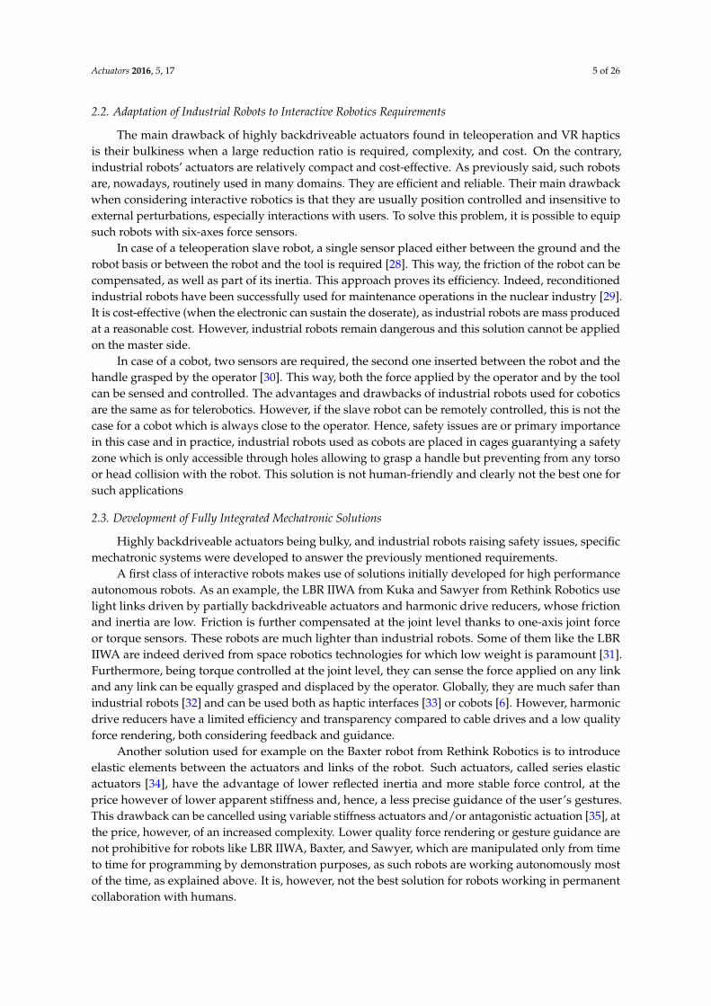
The main drawback of highly backdriveable actuators found in teleoperation and VR hapticsis their bulkiness when a large reduction ratio is required, complexity, and cost. On the contrary,industrial robots’ actuators are relatively compact and cost-effective. As previously said, such robotsare, nowadays, routinely used in many domains. They are efficient and reliable. Their main drawbackwhen considering interactive robotics is that they are usually position controlled and insensitive toexternal perturbations, especially interactions with users. To solve this problem, it is possible to equipsuch robots with six-axes force sensors.
In case of a teleoperation slave robot, a single sensor placed either between the ground and therobot basis or between the robot and the tool is required [28]. This way, the friction of the robot can becompensated, as well as part of its inertia. This approach proves its efficiency. Indeed, reconditionedindustrial robots have been successfully used for maintenance operations in the nuclear industry [29].It is cost-effective (when the electronic can sustain the doserate), as industrial robots are mass producedat a reasonable cost. However, industrial robots remain dangerous and this solution cannot be appliedon the master side.
In case of a cobot, two sensors are required, the second one inserted between the robot and thehandle grasped by the operator [30]. This way, both the force applied by the operator and by the toolcan be sensed and controlled. The advantages and drawbacks of industrial robots used for coboticsare the same as for telerobotics. However, if the slave robot can be remotely controlled, this is not thecase for a cobot which is always close to the operator. Hence, safety issues are or primary importancein this case and in practice, industrial robots used as cobots are placed in cages guarantying a safetyzone which is only accessible through holes allowing to grasp a handle but preventing from any torsoor head collision with the robot. This solution is not human-friendly and clearly not the best one forsuch applications
2.3. Development of Fully Integrated Mechatronic Solutions
Highly backdriveable actuators being bulky, and industrial robots raising safety issues, specificmechatronic systems were developed to answer the previously mentioned requirements.
A first class of interactive robots makes use of solutions initially developed for high performanceautonomous robots. As an example, the LBR IIWA from Kuka and Sawyer from Rethink Robotics uselight links driven by partially backdriveable actuators and harmonic drive reducers, whose frictionand inertia are low. Friction is further compensated at the joint level thanks to one-axis joint forceor torque sensors. These robots are much lighter than industrial robots. Some of them like the LBRIIWA are indeed derived from space robotics technologies for which low weight is paramount [31].Furthermore, being torque controlled at the joint level, they can sense the force applied on any linkand any link can be equally grasped and displaced by the operator. Globally, they are much safer thanindustrial robots [32] and can be used both as haptic interfaces [33] or cobots [6]. However, harmonicdrive reducers have a limited efficiency and transparency compared to cable drives and a low qualityforce rendering, both considering feedback and guidance.
Another solution used for example on the Baxter robot from Rethink Robotics is to introduceelastic elements between the actuators and links of the robot. Such actuators, called series elasticactuators [34], have the advantage of lower reflected inertia and more stable force control, at theprice however of lower apparent stiffness and, hence, a less precise guidance of the user’s gestures.This drawback can be cancelled using variable stiffness actuators and/or antagonistic actuation [35], atthe price, however, of an increased complexity. Lower quality force rendering or gesture guidance arenot prohibitive for robots like LBR IIWA, Baxter, and Sawyer, which are manipulated only from timeto time for programming by demonstration purposes, as such robots are working autonomously mostof the time, as explained above. It is, however, not the best solution for robots working in permanentcollaboration with humans.
Actuators 2016, 5, 17 6 of 26
2.4. Summary of the Advantages and Drawbacks of Existing Actuation Systems for Interactive Robotics
As highlighted above, several solutions exist for giving robots interactive capabilities. First of all,it is possible to equip existing industrial robots with force sensors to render them sensitive to externalforces applied by an operator. This solution is, however, not well suited for master arms, hapticinterfaces, and cobots, as industrial robots remain dangerous due to their large force capacity, highspeed, large inertia, and highly rigid links. As a consequence, they have to be physically separatedfrom the user. A second approach proposed in the literature is to use lighter and less powerfullightweight robots using either harmonic drive reducers or series elastic actuators. Their maximumspeed and force capacity are lower, and their joints are more compliant. All of these characteristicsmake them more human-friendly and allow using them close to human operators. However, theirlimited transparency, considering either friction or stiffness, leads to a limited quality force renderingand/or user guidance. This is not a real problem for robots with which humans interact only fromtime to time to program them by demonstration. It is, however, a real limitation for robots workingin permanent collaboration with humans, as for example exoskeletons or haptic interfaces. For thoserobots, mechanically highly backdrivable actuators developed for teleoperation and VR haptics appearas the best solution. Their main drawback is their bulkiness when a large reduction ratio is required,complexity and cost. The purpose of this paper is to introduce a new reducer called a differential cabledrive which circumvents these drawbacks. This reducer is presented in the next sections.
3. Design and Dimensioning of a Bi-Directional Differential Cable Drive Actuator
3.1. Genesis
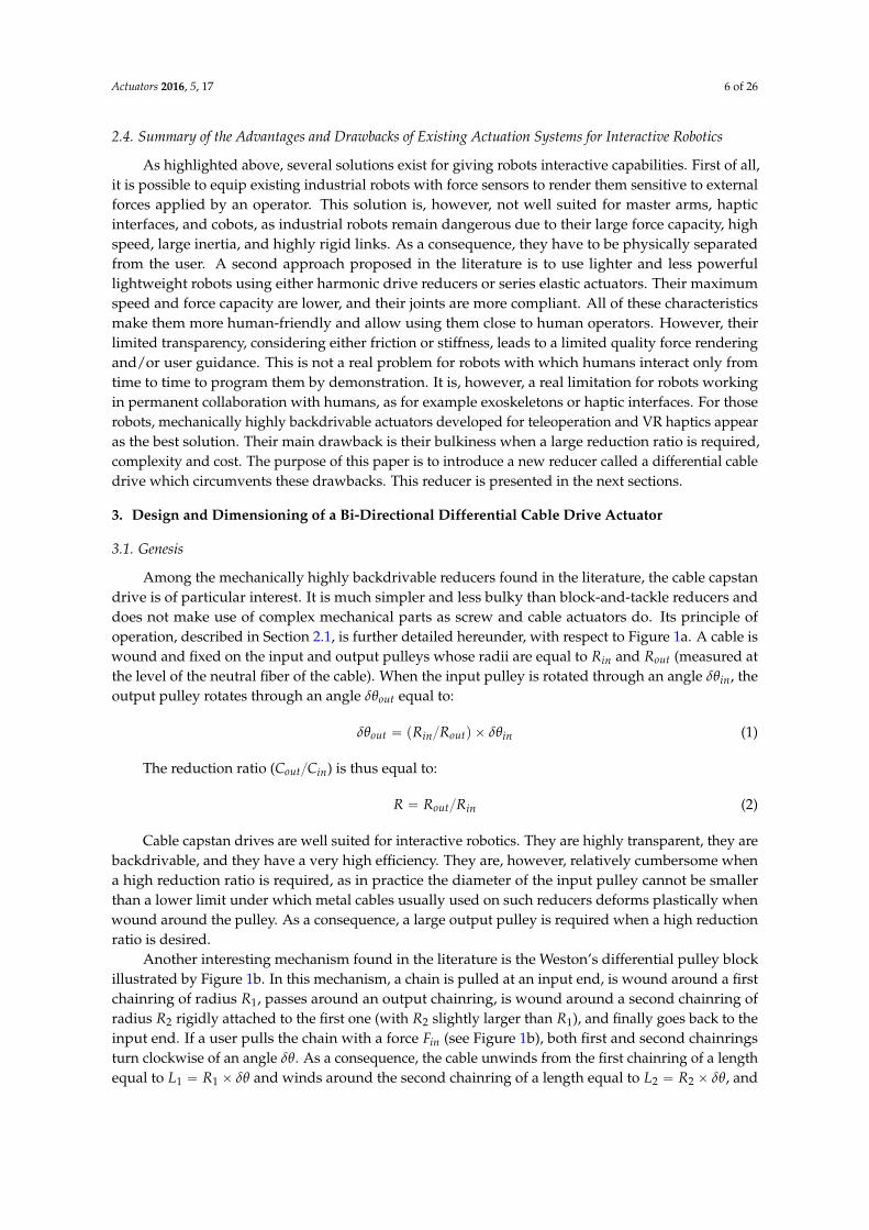
Among the mechanically highly backdrivable reducers found in the literature, the cable capstandrive is of particular interest. It is much simpler and less bulky than block-and-tackle reducers anddoes not make use of complex mechanical parts as screw and cable actuators do. Its principle ofoperation, described in Section 2.1, is further detailed hereunder, with respect to Figure 1a. A cable iswound and fixed on the input and output pulleys whose radii are equal to Rin and Rout (measured atthe level of the neutral fiber of the cable). When the input pulley is rotated through an angle δθin, theoutput pulley rotates through an angle δθout equal to:
δθout “ pRin{Routq ˆ δθin (1)
The reduction ratio (Cout{Cin) is thus equal to:
R “ Rout{Rin (2)
Cable capstan drives are well suited for interactive robotics. They are highly transparent, they arebackdrivable, and they have a very high efficiency. They are, however, relatively cumbersome whena high reduction ratio is required, as in practice the diameter of the input pulley cannot be smallerthan a lower limit under which metal cables usually used on such reducers deforms plastically whenwound around the pulley. As a consequence, a large output pulley is required when a high reductionratio is desired.
Another interesting mechanism found in the literature is the Weston’s differential pulley blockillustrated by Figure 1b. In this mechanism, a chain is pulled at an input end, is wound around a firstchainring of radius R1, passes around an output chainring, is wound around a second chainring ofradius R2 rigidly attached to the first one (with R2 slightly larger than R1), and finally goes back to theinput end. If a user pulls the chain with a force Fin (see Figure 1b), both first and second chainringsturn clockwise of an angle δθ. As a consequence, the cable unwinds from the first chainring of a lengthequal to L1 “ R1 ˆ δθ and winds around the second chainring of a length equal to L2 “ R2 ˆ δθ, and
Actuators 2016, 5, 17 7 of 26
the output pulley is lifted from a distance equal to half to difference, that is, Lout “ ppR2 ´ R1q {2q ˆ δθ.The corresponding distance travelled at the input end being Lin “ L2 “ R2 ˆ δθ, we get:
Lout “ ppR2 ´ R1q { p2ˆ R2qq ˆ Lin (3)
The reduction ratio (Fout{Fin) is, thus, equal to:
R “ p2ˆ R2q { pR2 ´ R1q (4)
Given a small difference between the radii of the chainrings, a very high reduction ratio can beobtained. Weston differential pulleys are indeed commonly used on manual chain hoists to lift veryheavy objects, like car engines. With chains, however, the chainrings’ radii are linked with the numberof teeth and cannot be chosen arbitrarily (the difference is usually one or a few teeth). Also, chainringscannot be made very small and the system is relatively cumbersome. While this is not a problem forworkshops’ hoists, it is not convenient for a robotic reducer.
Actuators 2016, 5, 17 7 of 26
chainrings cannot be made very small and the system is relatively cumbersome. While this is not a problem for workshops’ hoists, it is not convenient for a robotic reducer.
(a) (b) (c)
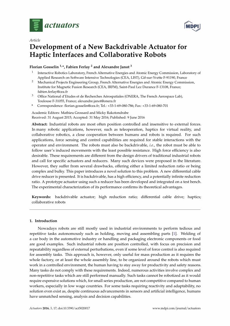
Figure 1. Principle of operation of state-of-the-art cable and chain reducers: (a) cable capstan drive, (b) Weston’s differential pulley block, and (c) cable differential pulleys.
Similar systems using cables instead of chains also exist (see Figure 1c). Such mechanisms, making use of a differential pulley, are commonly used for the purpose of teaching the theory of machines (see for example the wheel and differential axle proposed by P.A. Hilton Ltd, Stockbridge, UK, http//www.p-a-hilton.co.uk/). The principle of operation and the reduction ratio are the same as for the Weston’s differential pulley block. With a cable instead of a chain, however, the radii can be chosen arbitrarily close to each other, thus an even higher reduction ratio can be obtained. It is worth noting that, contrary to the cable capstan drive, the bulkiness of the system is independent of the reduction ratio, hence a potentially more compact solution when a high reduction ratio is required. Additionally, this mechanism remains highly transparent and backdrivable. However, in its current form, is can only pull an output load (mass M on Figure 1c) in one direction. This is not convenient for a robot’s joint which moves in opposite directions.
In this paper, we propose to combine two properly-synchronized input differential pulleys with an output pulley similar to a cable capstan drive’s one to control a robot joint. The principle of operation of such a bi-directional differential cable drive actuator, which combines the advantages of both systems, is explained in the next subsection.
3.2. Principle of Operation of the Differential Cable Drive Actuator
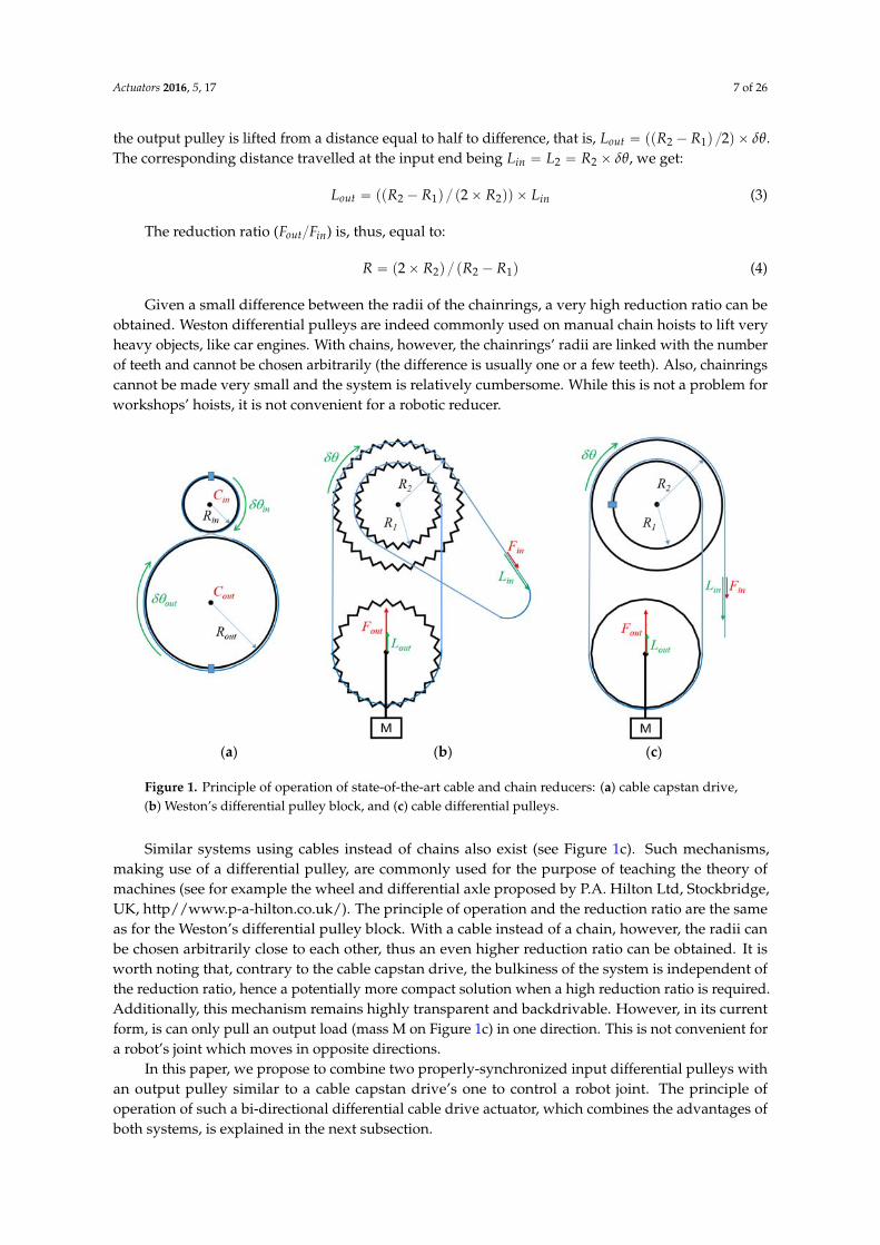
As shown in Figure 2, in order to obtain a high reduction ratio cable drive, we propose here to combine two synchronized input differential pulleys with an output pulley similar to a cable capstan drive’s one (in practice, the same differential pulley is used in both directions, the larger pulley in one direction being the smaller in the opposite direction, and vice versa). The principle of operation is similar to a Weston’s differential pulley block or cable differential pulleys, except that the differential pulleys are used here as the input instead of an intermediate block of pulleys (the cable being conversely used as an intermediate mean of transmission instead of the input of the system) and the pulley moving in translation is used here as an intermediate idler pulley, the output being a separate pulley similar to the output pulley of a cable capstan drive.
Figure 1. Principle of operation of state-of-the-art cable and chain reducers: (a) cable capstan drive,(b) Weston’s differential pulley block, and (c) cable differential pulleys.
Similar systems using cables instead of chains also exist (see Figure 1c). Such mechanisms,making use of a differential pulley, are commonly used for the purpose of teaching the theory ofmachines (see for example the wheel and differential axle proposed by P.A. Hilton Ltd, Stockbridge,UK, http//www.p-a-hilton.co.uk/). The principle of operation and the reduction ratio are the sameas for the Weston’s differential pulley block. With a cable instead of a chain, however, the radii canbe chosen arbitrarily close to each other, thus an even higher reduction ratio can be obtained. It isworth noting that, contrary to the cable capstan drive, the bulkiness of the system is independent ofthe reduction ratio, hence a potentially more compact solution when a high reduction ratio is required.Additionally, this mechanism remains highly transparent and backdrivable. However, in its currentform, is can only pull an output load (mass M on Figure 1c) in one direction. This is not convenient fora robot’s joint which moves in opposite directions.
In this paper, we propose to combine two properly-synchronized input differential pulleys withan output pulley similar to a cable capstan drive’s one to control a robot joint. The principle ofoperation of such a bi-directional differential cable drive actuator, which combines the advantages ofboth systems, is explained in the next subsection.
Actuators 2016, 5, 17 8 of 26
3.2. Principle of Operation of the Differential Cable Drive Actuator
As shown in Figure 2, in order to obtain a high reduction ratio cable drive, we propose hereto combine two synchronized input differential pulleys with an output pulley similar to a cablecapstan drive’s one (in practice, the same differential pulley is used in both directions, the largerpulley in one direction being the smaller in the opposite direction, and vice versa). The principle ofoperation is similar to a Weston’s differential pulley block or cable differential pulleys, except that thedifferential pulleys are used here as the input instead of an intermediate block of pulleys (the cablebeing conversely used as an intermediate mean of transmission instead of the input of the system)and the pulley moving in translation is used here as an intermediate idler pulley, the output beinga separate pulley similar to the output pulley of a cable capstan drive.Actuators 2016, 5, 17 8 of 26
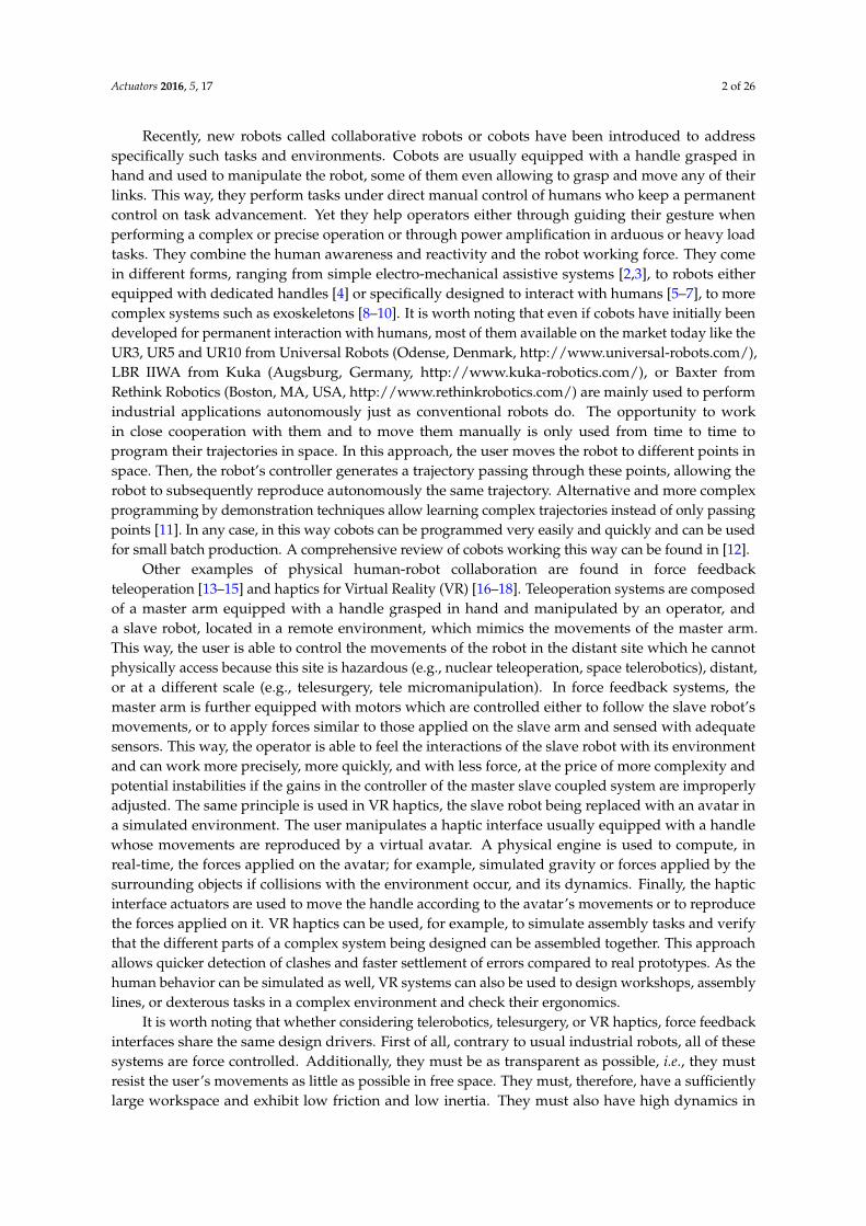
Figure 2. Principle of a differential cable drive.
A primary cable (thin solid lines in Figure 2) is attached to the first input pulley of radius , wound around a first idler pulley and attached to the second pulley of radius with . If the first input pulley turns clockwise of an angle , the cable unwinds from this pulley of a length equal to = × . Both input pulleys being attached together, the second input pulley also turns clockwise of an angle . Thus a length of cable equal to = × winds around it. As a consequence, the free part of the cable between the input pulleys shortens. For a rotation of an angle , the shortening equals half the difference (provided the cable is maintained in tension and the two cable strands between the input pulleys and the idler pulley are parallel) and the idler pulley gets closer to the input pulleys from a distance = ( − )/2 × . If the idler pulley is, itself, attached to an output pulley of radius through a secondary cable (large solid line in Figure 2), the later turns counterclockwise of an angle: = / = ( − )/(2 × ) × (5)
Hence, by denoting the (motor) input torque and the output (joint) torque, the reduction ratio of the differential cable drive is given by: = / = / = (2 × )/( − ) (6)
Conversely, a second idler pulley and a second strand of the primary cable and of the secondary cable (broken lines in Figure 2) are used to drive the output pulley clockwise.
As can be seen from Equation (6), the reduction ratio is no more defined as the ratio between some pulleys radii but as the ratio between the output pulley radius and the difference in input pulleys radii. This way, a very high, and potentially infinite, reduction ratio can be easily obtained. Therefore, one has only to manufacture input pulleys with a small difference in diameter. It is worth noting however that in case of a large reduction ratio, the force in the cables increases, and this introduces practical limitations due to cable compliance and resistance limits.
3.3. Dimensioning and Implementation
While the design presented in Figure 2 is relatively simple, its implementation requires the application of precise rules related to cable drive systems. These rules drive the choice of the actuator and cables and the dimensioning of the input, idler, and output pulleys, as well as of the whole reducer, as will be further detailed hereunder.
3.3.1. Actuator Selection
Haptic interfaces and collaborative robots usually make use of ironless DC motors (e.g., from Maxon Motor, Sachseln, Switzerland, http://www.maxonmotor.com/). These actuators have a very high peak torque, a very low inertia, and low cogging. They are also relatively simple to control compared to brushless actuators and come in a large range of sizes. Such actuators are commonly used on commercially available haptic interfaces such as, for example, the well-known Geomagic Touch, Geomagic Touch X and Sensable PHANToM Premium from Geomagic (Cary, NC, USA, http://www.geomagic.com/), Virtuose 3D and Virtuose 6D from Haption (Soulgé-sur-Ouette, France,
Figure 2. Principle of a differential cable drive.
A primary cable (thin solid lines in Figure 2) is attached to the first input pulley of radius Rin1,wound around a first idler pulley and attached to the second pulley of radius Rin2 with Rin2 ą Rin1.If the first input pulley turns clockwise of an angle δθin, the cable unwinds from this pulley of a lengthequal to Lin1 “ Rin1 ˆ δθin. Both input pulleys being attached together, the second input pulley alsoturns clockwise of an angle δθin. Thus a length of cable equal to Lin2 “ Rin2 ˆ δθin winds aroundit. As a consequence, the free part of the cable between the input pulleys shortens. For a rotation ofan angle δθin, the shortening equals half the difference (provided the cable is maintained in tensionand the two cable strands between the input pulleys and the idler pulley are parallel) and the idlerpulley gets closer to the input pulleys from a distance Lip “ ppRin2 ´ Rin1q {2q ˆ δθin. If the idler pulleyis, itself, attached to an output pulley of radius Rout through a secondary cable (large solid line inFigure 2), the later turns counterclockwise of an angle:
δθout “ Lip{Rout “ ppRin2 ´ Rin1q { p2ˆ Routqq ˆ δθin (5)
Hence, by denoting Cin the (motor) input torque and Cout the output (joint) torque, the reductionratio of the differential cable drive is given by:
R “ Cout{Cin “ δθin{δθout “ p2ˆ Routq { pRin2 ´ Rin1q (6)
Conversely, a second idler pulley and a second strand of the primary cable and of the secondarycable (broken lines in Figure 2) are used to drive the output pulley clockwise.
As can be seen from Equation (6), the reduction ratio is no more defined as the ratio between somepulleys radii but as the ratio between the output pulley radius and the difference in input pulleys radii.This way, a very high, and potentially infinite, reduction ratio can be easily obtained. Therefore, onehas only to manufacture input pulleys with a small difference in diameter. It is worth noting howeverthat in case of a large reduction ratio, the force in the cables increases, and this introduces practicallimitations due to cable compliance and resistance limits.

Actuators 2016, 5, 17 9 of 26
3.3. Dimensioning and Implementation
While the design presented in Figure 2 is relatively simple, its implementation requires theapplication of precise rules related to cable drive systems. These rules drive the choice of the actuatorand cables and the dimensioning of the input, idler, and output pulleys, as well as of the whole reducer,as will be further detailed hereunder.
3.3.1. Actuator Selection
Haptic interfaces and collaborative robots usually make use of ironless DC motors (e.g., fromMaxon Motor, Sachseln, Switzerland, http://www.maxonmotor.com/). These actuators havea very high peak torque, a very low inertia, and low cogging. They are also relatively simple tocontrol compared to brushless actuators and come in a large range of sizes. Such actuators arecommonly used on commercially available haptic interfaces such as, for example, the well-knownGeomagic Touch, Geomagic Touch X and Sensable PHANToM Premium from Geomagic (Cary, NC,USA, http://www.geomagic.com/), Virtuose 3D and Virtuose 6D from Haption (Soulgé-sur-Ouette,France, http://www.haption.com/), and delta.x, omega.x and sigma.x from Force Dimension (Nyon,Switzerland, http://www.forcedimension.com/).
In practice, these actuators are usually controlled using a PD (proportional and derivative)position controller (with gains denoted here Kcont and Bcont). The force τhi applied by the actuators ofthe haptic interface when the slave arm or virtual reality avatar is blocked against its environmentdepends on the difference between the current interface’s angular position qhi and speed
.qhi and the
slave robot’s or avatar’s data qre f and.qre f used as a reference [36], through the following equation:
τhi “ Kcont ˆ´
qre f ´ qhi
¯
` Bcont ˆ´ .
qre f ´.qhi
¯
(7)
Such a controller has the advantage of being passive, i.e., stable regardless the operator’scommands and the interactions with the environment. In practice, however, the gains allowing toensure stability are limited due to the spatial and temporal quantization of the measured positions [37],and must remain within given limits Kcont_max_actuator and Bcont_max_actuator. When the user tries to turnthe rotor of the motor, he feels a viscoelastic behavior. The highest stiffness that can be rendered isequal to Kcont_max_actuator, called here control stiffness. It is worth noting that these limitations occur atthe actuator level. When a reducer is used between the actuators and links, it can be demonstratedthat the stiffness sensed by the user at the joint level is proportional to the reduction ratio square.
Kcont_max_joint “ Kcont_max_actuator ˆ R2 (8)
When the user manipulates the interface through a handle fixed at the extremity of a link of lengthL, the apparent stiffness further depends on L. It can be expressed using the following equation:
Kcont_max_handle “ Kcont_max_actuator ˆ pR{Lq2 (9)
Hence, to allow for the simulation of rigid environments, the designer can either use highperformances actuators, sensors, and electronics (allowing to get a high value of Kcont_max_actuator),or high reduction ratios, or short links (at the price however of a limited workspace). Of course theactuators’ torques are further filtered by the interface’s mechanical structure.
The reader may observe that previous equations are written for a one degree of freedom (1DOF)interface. The same principle applies to multi DOFs robots, using a reduction matrix instead of a simplescalar reduction ratio, and the Jacobian of the robot instead of the link’s length.
From Equations (6) and (9), it can be seen that both the force capacity and control stiffness of thehaptic interface directly depend on the reduction ratio R and link’s length L. The choice of a givenactuator and reduction ratio, thus, depends on the desired maximum force feedback capacity and
Actuators 2016, 5, 17 10 of 26
apparent stiffness which are important design drivers for haptic interfaces and cobots. It can be noticedthat, for a given desired force, one can use either a large actuator with a small reducer, or a smallactuator and a large reducer, or any intermediate solution. A larger actuator usually allows minimizingcomplexity and friction, while a smaller actuator minimizes weight (provided the reducer’s increase inweight is not superior to the decrease in weight of the smaller motor) and maximizes the apparentstiffness (which is proportional to the reduction ratio square), even if smaller motors typically havea lower control stiffness than larger ones.
3.3.2. Cable Choice
As for the actuator, the choice of the cables is driven by the desired force and stiffness at theoutput of the system. Indeed, the secondary cable should be able to resist the force generated by theoutput joint. With Rout the radius of the output pulley and Cout_max the maximum desired outputtorque, the highest force in the secondary cable equals:
Fsc_max “ Cout_max{Rout (10)
Usually, a cable with a resistance of at least 2 times Fsc_max is chosen. It is worth noting that metalcables usually used in such reducers plastically deform when wound on small pulleys. For the mostflexible cables found on the market, the minimum diameter of the pulley is about 17 times the cablediameter. Hence, for a secondary cable of diameter dsc, we get Rout ě 8.5ˆ dsc (at the level of the cableneutral fiber), and the cable should have a resistance higher than Cout_max{ p8.5ˆ dscq.
The same holds for the primary cable. With the hypothesis that all cables remain parallel (seebelow) and under tension, the force in the primary cable is half the force in the secondary one. Hence, asmaller cable with a minimum resistance of Cout_max{ p17ˆ dscq is required.
It is worth noting that, as for the actuator, the stiffness of the cables should also be taken intoaccount when selecting them. Depending on the size of the system and range of motion, the length ofthe free strands of the cables (i.e., the sections of the cable in-between the pulleys) can be quite long,introducing flexibilities and decreasing the apparent stiffness sensed by the user. At first sight, thecontrol stiffness Kcont_max and cables stiffness Kcables (both computed in the same space, being eitherthe motor space, the joint space or the Cartesian space in which the handle moves) act in series, andboth are much lower than the link’s stiffness. Hence, the global apparent stiffness equals:
Kapp_max “´
K´1cont_max ` K´1
cables
¯´1(11)
Given a desired apparent stiffness and a control stiffness obtained as an output of the motorselection, the required cable stiffness can be computed. Under the assumption that all cables remainparallel and under tension, the four free strands of the primary cable act in parallel, so as the two freestrands of the secondary cable, both acting in series. Once the cables have been chosen, the designercan check if the desired stiffness is attained (taking into account the different configurations of therobot as the ratio between the length of the different strands depend on the output angle). If not, thecable selection can be improved.
3.3.3. Dimensioning of the Output Pulley
As said previously, the output pulley must have a minimum radius equal to Rout ě 8.5ˆ dsc.In practice, this radius is adjusted depending on other integration constraints, and can be higher thanthis minimum value.
3.3.4. Dimensioning of the Input Pulleys
Regarding the input pulleys, it must first of all be noted that the rotation of the differential pulleyscan be quite large for high reduction ratio. As an example, for a reduction ratio of R = 60 and a range
Actuators 2016, 5, 17 11 of 26
of motion δθout = 120˝ at the joint level, the differential pulley rotates 20 turns (from Equation (6), wehave δθin “ Rˆ δθout “ 7200˝).
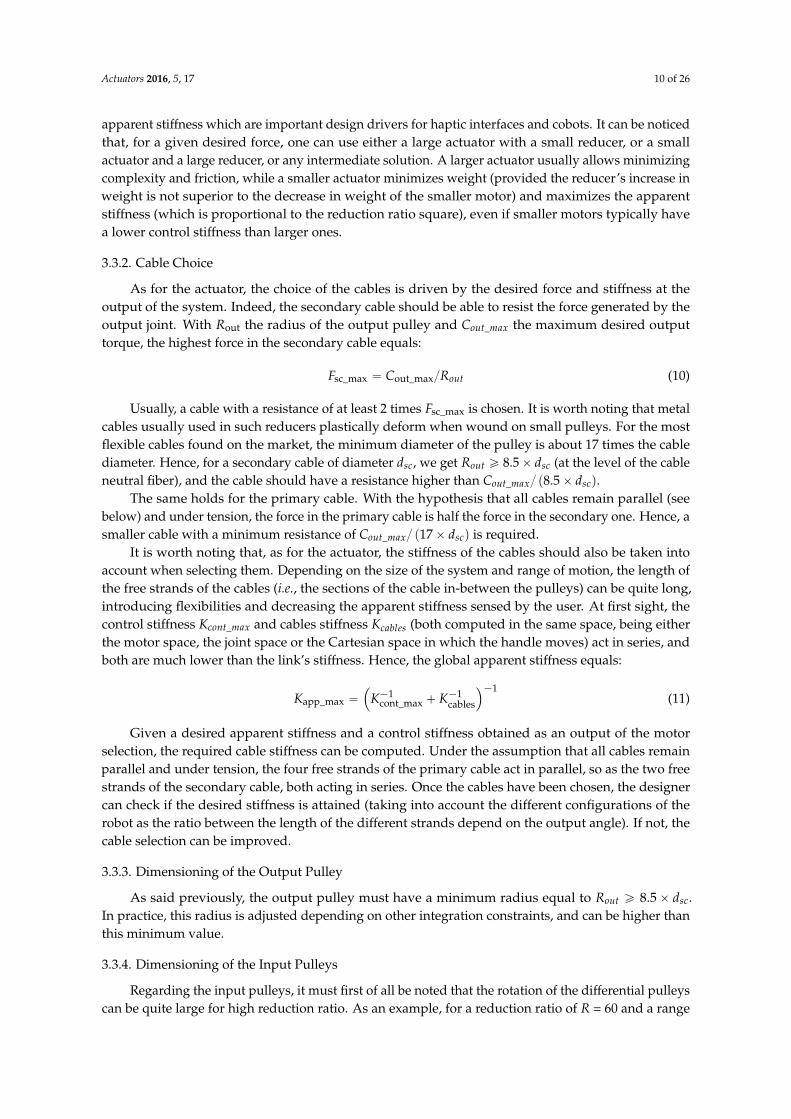
The readers must also keep in mind that, as already said in Section 2.1, cables have to be woundin spirals around the input pulleys. In practice, to properly guide the cables around the pulleys andavoid any possible overlap, a spiral thread is usually machined at the surface of the pulleys, witha thread pitch p slightly larger than the primary cable diameter dpc (typically about 1.25 times thecable diameter), the latter depending on the force transmitted in the cable. As a consequence, the cabletravels a distance along the pulley axis equal to the number of turns times the thread pitch. Referringto the above example, if 20 turns are required and if a thin primary metal cable of diameter 1 mm asoften found in haptic interfaces’ cable drives is used, the cable travels 25 mm along the pulley axiswhen the joint turns 120˝. This result holds, of course, for both the large and the small pulleys ofthe differential.
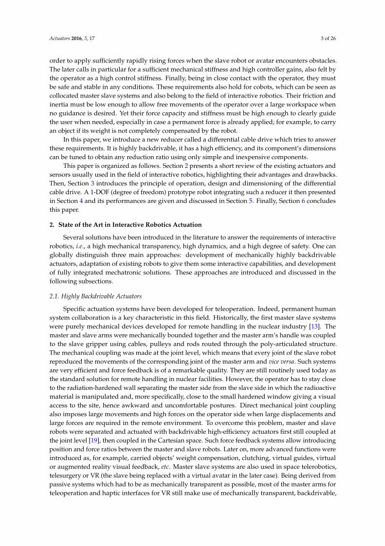
The last point to mention is the cable fixation on the pulleys. This can be made with screws.In this case the pulleys should be sufficiently long to integrate the screws whose head diameter usuallyrepresents about three or four turns for small cables, as presented above. Alternatively, the cables cansimply be locked by friction. The friction between the cable and pulley being an exponential functionof the winding angle, it does not slide on the input pulley if this angle is sufficient. In practice, four tofive turns are usually sufficient to avoid cable slippage. Both methods are illustrated in Figure 3,which also summarizes the aforementioned dimensioning rules (in Figure 3, the input pulleys arerepresented at the center of the workspace with the hypothesis that the joint can turn δθout{2 clockwiseand counterclockwise, the global range of motion being equal to δθout).
Actuators 2016, 5, 17 11 of 26
represented at the center of the workspace with the hypothesis that the joint can turn /2 clockwise and counterclockwise, the global range of motion being equal to ).
Figure 3. General rules of dimensioning of the input and idler pulleys.
One can see that the length of the input pulley is smaller with a cable friction locking compared to screw attachments. One could conclude that friction locking is desirable on both pulleys. This would however require a closed cable loop. This in turn would require both ends of the cable to be attached together. This would result in practice in a cable bulge which would introduce perturbations when the cable is wound around the pulleys. To avoid this problem, we recommend a cable friction locking on one pulley and a screw attachment on the second one.
It is also worth noting that Equations (5) and (6) require that the primary cable strands remain parallel to each other. If not, the geometry of the quadrangle formed by the input and output points of the primary cable on the input pulleys and each of the idler pulleys will deform when the system moves, consuming part of the elongation or shortening of the cable and modifying the reduction ratio which would further depend on the joint angle. This parallelism introduces constraints on both the input and idler pulleys dimensions (see below for the later). In particular, one can see from Figure 3 that the primary cables will “advance” along the input pulleys when the system moves. If the direction of the spiral thread is not the same on both pulleys, the distance between the input and output points of the primary cable on the input pulleys, and hence the angle between the primary cable strands, will change as a function of the pulleys’ angle. To maintain these strands parallel, the direction of the spiral thread must be the same on both input pulleys. Additionally, we introduce a small distance between the two strands going in and out of the input pulley with screw attachments in order to avoid the cable strands to collide and rub against each other. In practice, this distance is set at the same value as the length of the friction locking on the other pulley (see details below).
Regarding the pulleys’ diameter, it is mostly limited by the minimum winding diameter of the primary cable, with the same rules as for the secondary cable, i.e., & ≥ 8.5 × . Then, the difference in pulleys diameter is directly function of the chosen actuator which fixes the reduction ratio and the output pulley’s radius through Equation (6).
3.3.5. Dimensioning of the Idler Pulleys
For the same reason as explained above, the diameter of the idler pulleys must be equal to the distance between the output point of the primary cable from one input pulley and its input point on the second input pulley. If not, the cable strands will not remain parallel as the system moves.
Figure 3. General rules of dimensioning of the input and idler pulleys.
One can see that the length of the input pulley is smaller with a cable friction locking compared toscrew attachments. One could conclude that friction locking is desirable on both pulleys. This wouldhowever require a closed cable loop. This in turn would require both ends of the cable to be attachedtogether. This would result in practice in a cable bulge which would introduce perturbations when thecable is wound around the pulleys. To avoid this problem, we recommend a cable friction locking onone pulley and a screw attachment on the second one.
It is also worth noting that Equations (5) and (6) require that the primary cable strands remainparallel to each other. If not, the geometry of the quadrangle formed by the input and output pointsof the primary cable on the input pulleys and each of the idler pulleys will deform when the systemmoves, consuming part of the elongation or shortening of the cable and modifying the reduction ratiowhich would further depend on the joint angle. This parallelism introduces constraints on both the
Actuators 2016, 5, 17 12 of 26
input and idler pulleys dimensions (see below for the later). In particular, one can see from Figure 3that the primary cables will “advance” along the input pulleys when the system moves. If the directionof the spiral thread is not the same on both pulleys, the distance between the input and output pointsof the primary cable on the input pulleys, and hence the angle between the primary cable strands, willchange as a function of the pulleys’ angle. To maintain these strands parallel, the direction of the spiralthread must be the same on both input pulleys. Additionally, we introduce a small distance betweenthe two strands going in and out of the input pulley with screw attachments in order to avoid the cablestrands to collide and rub against each other. In practice, this distance is set at the same value as thelength of the friction locking on the other pulley (see details below).
Regarding the pulleys’ diameter, it is mostly limited by the minimum winding diameter of theprimary cable, with the same rules as for the secondary cable, i.e., Rin1&Rin2 ě 8.5ˆ dpc. Then, thedifference in pulleys diameter is directly function of the chosen actuator which fixes the reduction ratioand the output pulley’s radius through Equation (6).
3.3.5. Dimensioning of the Idler Pulleys
For the same reason as explained above, the diameter of the idler pulleys must be equal to thedistance between the output point of the primary cable from one input pulley and its input point onthe second input pulley. If not, the cable strands will not remain parallel as the system moves.
With the approximation that the angle between the input and output points of the primary cableon the input pulleys equals 180˝, the diameter of the idler pulleys can be computed using the followingformula (see Figure 3 for the notations):
dip1 “
c
pRin2 ´ Rin1q2`
´
Lrom ` Lsh ` L f s ` 1¯2
(12)
dip2 “
c
pRin2 ´ Rin1q2`
´
Lrom ` L f l ` Lsh ` 1¯2
(13)
On can see that the idler pulleys can have the same diameter if the distance between thetwo strands going in and out of the input pulley with screw attachments is equal to the lengthof the friction locking (L f s “ L f l). In order to simplify the design and manufacturing of the system, werecommend respecting this constraint.
3.3.6. Global Dimensioning of the System
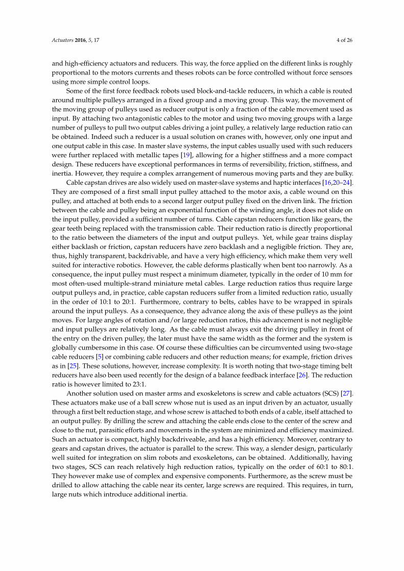
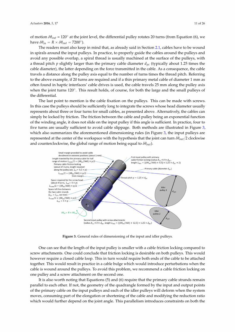
The radii of the different pulleys being known, the distance between the input and output pulleyscan be fixed. Indeed, as shown on Figure 4, when the output pulley turns of an angle ˘δθout{2, theidler pulleys travel a distance equal to Lip “ ˘pδθout{2q ˆ Rout. Hence, the distance between theinput and output pulleys must be larger than dip1 ` Lip and dip2 ` Lip plus a small margin to avoidinter-pulley collisions. It is worth noting that, as can be seen from Figures 3 and 4, some primary cablescross the paths of the idler pulleys when the latter moves toward the input pulleys. As a consequence,the distance between the pulleys must be increased to avoid collisions between the cables and idlerpulleys. In practice, the occurrence of these collisions depends on the pulleys diameter and on the anglebetween the cables going in both directions and the distance between the input and output pulleysmust be adjusted iteratively until no collision remains. This can be accomplished with a CAD software.
It is also worth noting that, as the input cables “advance” along the input pulleys when thesystem rotates, the distance between the point Pin1 (respectively, Pin2) defined as the middle of theinput and output points of the primary cable on the input pulleys and the point Pout1 (respectively,Pout2) defined as the input of the secondary cable on the output pulley (this distance can be consideredas some “virtual” length of the cables between the input and output pulleys) varies as a function of theoutput joint’s angle. As a consequence, the length of the free cable strands slightly changes when thesystem moves. In practice, however, the aforementioned constraints impose that the “virtual” length
Actuators 2016, 5, 17 13 of 26
of the cables is very large compared to the cable advance along the pulleys’ axis and this elongation isnegligible. As an example, the maximum elongation of the cables of the prototype presented belowequals 0.14% of the cables’ length [38].
Actuators 2016, 5, 17 12 of 26
With the approximation that the angle between the input and output points of the primary cable on the input pulleys equals 180°, the diameter of the idler pulleys can be computed using the following formula (see Figure 3 for the notations): = ( − ) + ( + + + 1) (12)
= ( − ) + ( + + + 1) (13)
On can see that the idler pulleys can have the same diameter if the distance between the two strands going in and out of the input pulley with screw attachments is equal to the length of the friction locking ( = ). In order to simplify the design and manufacturing of the system, we recommend respecting this constraint.
3.3.6. Global Dimensioning of the System
The radii of the different pulleys being known, the distance between the input and output pulleys can be fixed. Indeed, as shown on Figure 4, when the output pulley turns of an angle /2, the idler pulleys travel a distance equal to = ( /2) × . Hence, the distance between the input and output pulleys must be larger than + and + plus a small margin to avoid inter-pulley collisions. It is worth noting that, as can be seen from Figures 3 and 4, some primary cables cross the paths of the idler pulleys when the latter moves toward the input pulleys. As a consequence, the distance between the pulleys must be increased to avoid collisions between the cables and idler pulleys. In practice, the occurrence of these collisions depends on the pulleys diameter and on the angle between the cables going in both directions and the distance between the input and output pulleys must be adjusted iteratively until no collision remains. This can be accomplished with a CAD software.
Figure 4. Global dimensioning of the differential cable drive.
It is also worth noting that, as the input cables “advance” along the input pulleys when the system rotates, the distance between the point (respectively, ) defined as the middle of the input and output points of the primary cable on the input pulleys and the point (respectively,
) defined as the input of the secondary cable on the output pulley (this distance can be considered as some “virtual” length of the cables between the input and output pulleys) varies as a function of the output joint’s angle. As a consequence, the length of the free cable strands slightly changes when the system moves. In practice, however, the aforementioned constraints impose that the “virtual” length of the cables is very large compared to the cable advance along the pulleys’ axis and this elongation is negligible. As an example, the maximum elongation of the cables of the prototype presented below equals 0.14% of the cables’ length [38].
Figure 4. Global dimensioning of the differential cable drive.
3.3.7. Dimensioning Methodology
The equations presented above theoretically allow the successive dimensioning of the differentcomponents. In practice, the different choices are interdependent and the dimensioning of a differentialcable drive is an iterative process.
Additionally, the theoretical values obtained as an output of the dimensioning process can beadapted due to other constraints as for example integration or cost constraints.
4. Development and Manufacturing of a Differential Cable Drive Actuator Prototype
4.1. Context of the Study
Given the potential advantages of differential cable drives, we decided to develop a 1-DOFprototype robot integrating such a reducer. In order to set the design drivers, we selected as a use-casea maxilla facial surgery simulator developed within the framework of the European Integrated ProjectSKILLS (IST-FP6 #035005, 2006–2011). This use-case has stringent requirements in terms of bothtransparency in free space and force quality rendering when force feedback is required, for whichdifferential cable drives appear as a promising solution.
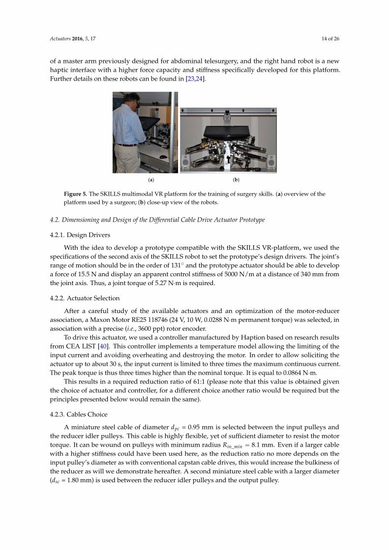
This simulator is a multimodal VR platform for the training of surgery skills [39], focusing morespecifically on an operation called the Epker osteotomy which consists in moving the lower mandibleforward or backward to correct an improper positioning of the teeth in the case of malformation or trauma.Therefore, the surgeon has in particular to drill the mandible bones. Experimental measurements madewith a motion capture system and a force sensor during a data acquisition campaign performed in theanatomy laboratory of a university hospital with which we collaborated during these developmentshave shown that the most critical steps of this surgery require bi-manual movements in the Cartesianspace with a maximum amplitude at the level of the surgery tool handle of about 162 to 194 mm intranslation and 137˝ in orientation. The maximum measured efforts on the handle are in the orderof 25 N and 1.5 N¨m (also in the Cartesian space). Finally, the bone stiffness is about 10,000 N/m.To allow for the simulation of this surgery, similar displacements and forces have to be reproducedat the level of the robot’s handle. Therefore, we developed two robots (one for each hand) havinga hybrid serial and parallel architecture. As shown on Figure 5, these robots are composed of two3-DOFs sub-structures connected together at their tip and equipped with an additional pivot DOF inseries. This structure combines the advantages of serial (large workspace in orientation) and parallelrobots (good transparency in orientation). In practice, the left hand robot is a reconditioned version
Actuators 2016, 5, 17 14 of 26
of a master arm previously designed for abdominal telesurgery, and the right hand robot is a newhaptic interface with a higher force capacity and stiffness specifically developed for this platform.Further details on these robots can be found in [23,24].
Actuators 2016, 5, 17 13 of 26
3.3.7. Dimensioning Methodology
The equations presented above theoretically allow the successive dimensioning of the different components. In practice, the different choices are interdependent and the dimensioning of a differential cable drive is an iterative process.
Additionally, the theoretical values obtained as an output of the dimensioning process can be adapted due to other constraints as for example integration or cost constraints.
4. Development and Manufacturing of a Differential Cable Drive Actuator Prototype
4.1. Context of the Study
Given the potential advantages of differential cable drives, we decided to develop a 1-DOF prototype robot integrating such a reducer. In order to set the design drivers, we selected as a use-case a maxilla facial surgery simulator developed within the framework of the European Integrated Project SKILLS (IST-FP6 #035005, 2006–2011). This use-case has stringent requirements in terms of both transparency in free space and force quality rendering when force feedback is required, for which differential cable drives appear as a promising solution.
This simulator is a multimodal VR platform for the training of surgery skills [39], focusing more specifically on an operation called the Epker osteotomy which consists in moving the lower mandible forward or backward to correct an improper positioning of the teeth in the case of malformation or trauma. Therefore, the surgeon has in particular to drill the mandible bones. Experimental measurements made with a motion capture system and a force sensor during a data acquisition campaign performed in the anatomy laboratory of a university hospital with which we collaborated during these developments have shown that the most critical steps of this surgery require bi-manual movements in the Cartesian space with a maximum amplitude at the level of the surgery tool handle of about 162 to 194 mm in translation and 137° in orientation. The maximum measured efforts on the handle are in the order of 25 N and 1.5 N∙m (also in the Cartesian space). Finally, the bone stiffness is about 10,000 N/m. To allow for the simulation of this surgery, similar displacements and forces have to be reproduced at the level of the robot’s handle. Therefore, we developed two robots (one for each hand) having a hybrid serial and parallel architecture. As shown on Figure 5, these robots are composed of two 3-DOFs sub-structures connected together at their tip and equipped with an additional pivot DOF in series. This structure combines the advantages of serial (large workspace in orientation) and parallel robots (good transparency in orientation). In practice, the left hand robot is a reconditioned version of a master arm previously designed for abdominal telesurgery, and the right hand robot is a new haptic interface with a higher force capacity and stiffness specifically developed for this platform. Further details on these robots can be found in [23,24].
(a) (b)
Figure 5. The SKILLS multimodal VR platform for the training of surgery skills. (a) overview of the platform used by a surgeon; (b) close-up view of the robots. Figure 5. The SKILLS multimodal VR platform for the training of surgery skills. (a) overview of the
platform used by a surgeon; (b) close-up view of the robots.
4.2. Dimensioning and Design of the Differential Cable Drive Actuator Prototype
4.2.1. Design Drivers
With the idea to develop a prototype compatible with the SKILLS VR-platform, we used thespecifications of the second axis of the SKILLS robot to set the prototype’s design drivers. The joint’srange of motion should be in the order of 131˝ and the prototype actuator should be able to developa force of 15.5 N and display an apparent control stiffness of 5000 N/m at a distance of 340 mm fromthe joint axis. Thus, a joint torque of 5.27 N¨m is required.
4.2.2. Actuator Selection
After a careful study of the available actuators and an optimization of the motor-reducerassociation, a Maxon Motor RE25 118746 (24 V, 10 W, 0.0288 N¨m permanent torque) was selected, inassociation with a precise (i.e., 3600 ppt) rotor encoder.
To drive this actuator, we used a controller manufactured by Haption based on research resultsfrom CEA LIST [40]. This controller implements a temperature model allowing the limiting of theinput current and avoiding overheating and destroying the motor. In order to allow soliciting theactuator up to about 30 s, the input current is limited to three times the maximum continuous current.The peak torque is thus three times higher than the nominal torque. It is equal to 0.0864 N¨m.
This results in a required reduction ratio of 61:1 (please note that this value is obtained giventhe choice of actuator and controller, for a different choice another ratio would be required but theprinciples presented below would remain the same).
4.2.3. Cables Choice
A miniature steel cable of diameter dpc = 0.95 mm is selected between the input pulleys andthe reducer idler pulleys. This cable is highly flexible, yet of sufficient diameter to resist the motortorque. It can be wound on pulleys with minimum radius Rin_min “ 8.1 mm. Even if a larger cablewith a higher stiffness could have been used here, as the reduction ratio no more depends on theinput pulley’s diameter as with conventional capstan cable drives, this would increase the bulkiness ofthe reducer as will we demonstrate hereafter. A second miniature steel cable with a larger diameter(dsc = 1.80 mm) is used between the reducer idler pulleys and the output pulley.
Actuators 2016, 5, 17 15 of 26
4.2.4. Dimensioning of the Output Pulley
With a secondary cable of diameter dsc = 1.80 mm, the output pulley’s radius should be largerthan Rout_min “ 15.3 mm. In practice, however, as shown on Figure 6, the differential cable drivestudied in this section differs from the system shown on Figures 2 and 4 from two respects.
Firstly, the device is statically balanced with a counterweight. Such a counterbalancing system,being either passive or active, is necessary on haptic interfaces in order to limit the fatigue of the userand avoid the system to fall in case the user drops the handle. To be efficient, such a counterweightshould be either sufficiently heavy or placed at a sufficient distance from the joint’s axis. The maximumreasonable weight fixed the distance which in turn constrained the pulley’s diameter (we choseto directly fix the counterweight on the output pulley). This results in an output pulley of radiusRout = 50 mm (at the level of the neutral cable fiber).
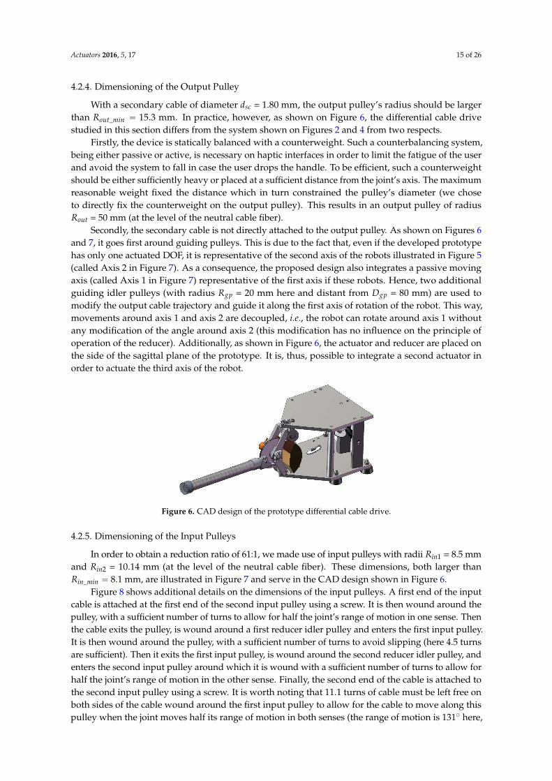
Secondly, the secondary cable is not directly attached to the output pulley. As shown on Figures 6and 7, it goes first around guiding pulleys. This is due to the fact that, even if the developed prototypehas only one actuated DOF, it is representative of the second axis of the robots illustrated in Figure 5(called Axis 2 in Figure 7). As a consequence, the proposed design also integrates a passive movingaxis (called Axis 1 in Figure 7) representative of the first axis if these robots. Hence, two additionalguiding idler pulleys (with radius Rgp = 20 mm here and distant from Dgp = 80 mm) are used tomodify the output cable trajectory and guide it along the first axis of rotation of the robot. This way,movements around axis 1 and axis 2 are decoupled, i.e., the robot can rotate around axis 1 withoutany modification of the angle around axis 2 (this modification has no influence on the principle ofoperation of the reducer). Additionally, as shown in Figure 6, the actuator and reducer are placed onthe side of the sagittal plane of the prototype. It is, thus, possible to integrate a second actuator inorder to actuate the third axis of the robot.
Actuators 2016, 5, 17 15 of 26
principle of operation of the reducer). Additionally, as shown in Figure 6, the actuator and reducer are placed on the side of the sagittal plane of the prototype. It is, thus, possible to integrate a second actuator in order to actuate the third axis of the robot.
Figure 6. CAD design of the prototype differential cable drive.
4.2.5. Dimensioning of the Input Pulleys
In order to obtain a reduction ratio of 61:1, we made use of input pulleys with radii = 8.5 mm and = 10.14 mm (at the level of the neutral cable fiber). These dimensions, both larger than _ = 8.1 mm, are illustrated in Figure 7 and serve in the CAD design shown in Figure 6.
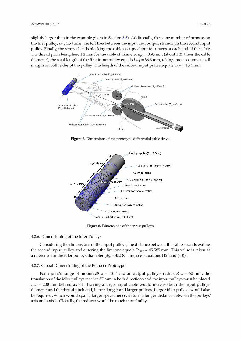
Figure 7. Dimensions of the prototype differential cable drive.
Figure 8 shows additional details on the dimensions of the input pulleys. A first end of the input cable is attached at the first end of the second input pulley using a screw. It is then wound around the pulley, with a sufficient number of turns to allow for half the joint’s range of motion in one sense. Then the cable exits the pulley, is wound around a first reducer idler pulley and enters the first input pulley. It is then wound around the pulley, with a sufficient number of turns to avoid slipping (here 4.5 turns are sufficient). Then it exits the first input pulley, is wound around the second reducer idler pulley, and enters the second input pulley around which it is wound with a sufficient number of turns to allow for half the joint’s range of motion in the other sense. Finally, the second end of the cable is attached to the second input pulley using a screw. It is worth noting that 11.1 turns of cable must be left free on both sides of the cable wound around the first input pulley to allow for the cable
Figure 6. CAD design of the prototype differential cable drive.
4.2.5. Dimensioning of the Input Pulleys
In order to obtain a reduction ratio of 61:1, we made use of input pulleys with radii Rin1 = 8.5 mmand Rin2 = 10.14 mm (at the level of the neutral cable fiber). These dimensions, both larger thanRin_min “ 8.1 mm, are illustrated in Figure 7 and serve in the CAD design shown in Figure 6.
Figure 8 shows additional details on the dimensions of the input pulleys. A first end of the inputcable is attached at the first end of the second input pulley using a screw. It is then wound around thepulley, with a sufficient number of turns to allow for half the joint’s range of motion in one sense. Thenthe cable exits the pulley, is wound around a first reducer idler pulley and enters the first input pulley.It is then wound around the pulley, with a sufficient number of turns to avoid slipping (here 4.5 turnsare sufficient). Then it exits the first input pulley, is wound around the second reducer idler pulley, andenters the second input pulley around which it is wound with a sufficient number of turns to allow forhalf the joint’s range of motion in the other sense. Finally, the second end of the cable is attached tothe second input pulley using a screw. It is worth noting that 11.1 turns of cable must be left free onboth sides of the cable wound around the first input pulley to allow for the cable to move along thispulley when the joint moves half its range of motion in both senses (the range of motion is 131˝ here,
Actuators 2016, 5, 17 16 of 26
slightly larger than in the example given in Section 3.3). Additonally, the same number of turns as onthe first pulley, i.e., 4.5 turns, are left free between the input and output strands on the second inputpulley. Finally, the screws heads blocking the cable occupy about four turns at each end of the cable.The thread pitch being here 1.2 mm for the cable of diameter dpc = 0.95 mm (about 1.25 times the cablediameter), the total length of the first input pulley equals Lin1 = 36.8 mm, taking into account a smallmargin on both sides of the pulley. The length of the second input pulley equals Lin2 = 46.4 mm.
Actuators 2016, 5, 17 15 of 26
principle of operation of the reducer). Additionally, as shown in Figure 6, the actuator and reducer are placed on the side of the sagittal plane of the prototype. It is, thus, possible to integrate a second actuator in order to actuate the third axis of the robot.
Figure 6. CAD design of the prototype differential cable drive.
4.2.5. Dimensioning of the Input Pulleys
In order to obtain a reduction ratio of 61:1, we made use of input pulleys with radii = 8.5 mm and = 10.14 mm (at the level of the neutral cable fiber). These dimensions, both larger than _ = 8.1 mm, are illustrated in Figure 7 and serve in the CAD design shown in Figure 6.
Figure 7. Dimensions of the prototype differential cable drive.
Figure 8 shows additional details on the dimensions of the input pulleys. A first end of the input cable is attached at the first end of the second input pulley using a screw. It is then wound around the pulley, with a sufficient number of turns to allow for half the joint’s range of motion in one sense. Then the cable exits the pulley, is wound around a first reducer idler pulley and enters the first input pulley. It is then wound around the pulley, with a sufficient number of turns to avoid slipping (here 4.5 turns are sufficient). Then it exits the first input pulley, is wound around the second reducer idler pulley, and enters the second input pulley around which it is wound with a sufficient number of turns to allow for half the joint’s range of motion in the other sense. Finally, the second end of the cable is attached to the second input pulley using a screw. It is worth noting that 11.1 turns of cable must be left free on both sides of the cable wound around the first input pulley to allow for the cable
Figure 7. Dimensions of the prototype differential cable drive.
Figure 8. Dimensions of the input pulleys.
4.2.6. Dimensioning of the Idler Pulleys
Considering the dimensions of the input pulleys, the distance between the cable strands exitingthe second input pulley and entering the first one equals Dio12 = 45.585 mm. This value is taken asa reference for the idler pulleys diameter (dip = 45.585 mm, see Equations (12) and (13)).
4.2.7. Global Dimensioning of the Reducer Prototype
For a joint’s range of motion δθout = 131˝ and an output pulley’s radius Rout = 50 mm, thetranslation of the idler pulleys reaches 57 mm in both directions and the input pulleys must be placedLred = 200 mm behind axis 1. Having a larger input cable would increase both the input pulleysdiameter and the thread pitch and, hence, longer and larger pulleys. Larger idler pulleys would alsobe required, which would span a larger space, hence, in turn a longer distance between the pulleys’axis and axis 1. Globally, the reducer would be much more bulky.
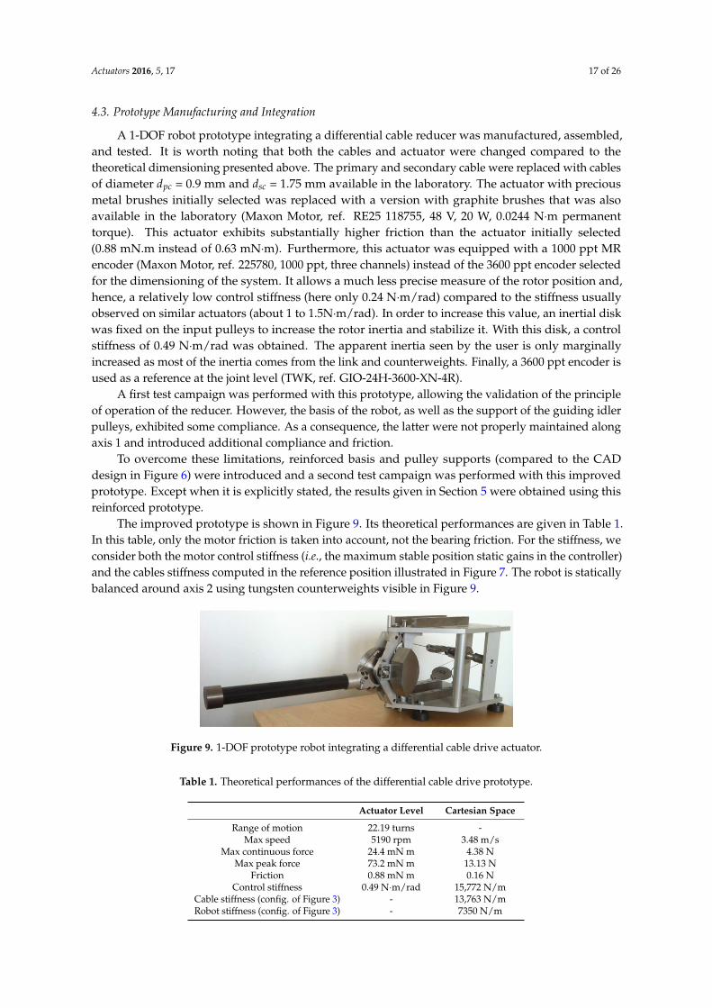
Actuators 2016, 5, 17 17 of 26
4.3. Prototype Manufacturing and Integration
A 1-DOF robot prototype integrating a differential cable reducer was manufactured, assembled,and tested. It is worth noting that both the cables and actuator were changed compared to thetheoretical dimensioning presented above. The primary and secondary cable were replaced with cablesof diameter dpc = 0.9 mm and dsc = 1.75 mm available in the laboratory. The actuator with preciousmetal brushes initially selected was replaced with a version with graphite brushes that was alsoavailable in the laboratory (Maxon Motor, ref. RE25 118755, 48 V, 20 W, 0.0244 N¨m permanenttorque). This actuator exhibits substantially higher friction than the actuator initially selected(0.88 mN.m instead of 0.63 mN¨m). Furthermore, this actuator was equipped with a 1000 ppt MRencoder (Maxon Motor, ref. 225780, 1000 ppt, three channels) instead of the 3600 ppt encoder selectedfor the dimensioning of the system. It allows a much less precise measure of the rotor position and,hence, a relatively low control stiffness (here only 0.24 N¨m/rad) compared to the stiffness usuallyobserved on similar actuators (about 1 to 1.5N¨m/rad). In order to increase this value, an inertial diskwas fixed on the input pulleys to increase the rotor inertia and stabilize it. With this disk, a controlstiffness of 0.49 N¨m/rad was obtained. The apparent inertia seen by the user is only marginallyincreased as most of the inertia comes from the link and counterweights. Finally, a 3600 ppt encoder isused as a reference at the joint level (TWK, ref. GIO-24H-3600-XN-4R).
A first test campaign was performed with this prototype, allowing the validation of the principleof operation of the reducer. However, the basis of the robot, as well as the support of the guiding idlerpulleys, exhibited some compliance. As a consequence, the latter were not properly maintained alongaxis 1 and introduced additional compliance and friction.
To overcome these limitations, reinforced basis and pulley supports (compared to the CADdesign in Figure 6) were introduced and a second test campaign was performed with this improvedprototype. Except when it is explicitly stated, the results given in Section 5 were obtained using thisreinforced prototype.
The improved prototype is shown in Figure 9. Its theoretical performances are given in Table 1.In this table, only the motor friction is taken into account, not the bearing friction. For the stiffness, weconsider both the motor control stiffness (i.e., the maximum stable position static gains in the controller)and the cables stiffness computed in the reference position illustrated in Figure 7. The robot is staticallybalanced around axis 2 using tungsten counterweights visible in Figure 9.
Actuators 2016, 5, 17 17 of 26
for the dimensioning of the system. It allows a much less precise measure of the rotor position and, hence, a relatively low control stiffness (here only 0.24 N∙m/rad) compared to the stiffness usually observed on similar actuators (about 1 to 1.5N∙m/rad). In order to increase this value, an inertial disk was fixed on the input pulleys to increase the rotor inertia and stabilize it. With this disk, a control stiffness of 0.49 N∙m/rad was obtained. The apparent inertia seen by the user is only marginally increased as most of the inertia comes from the link and counterweights. Finally, a 3600 ppt encoder is used as a reference at the joint level (TWK, ref. GIO-24H-3600-XN-4R).
A first test campaign was performed with this prototype, allowing the validation of the principle of operation of the reducer. However, the basis of the robot, as well as the support of the guiding idler pulleys, exhibited some compliance. As a consequence, the latter were not properly maintained along axis 1 and introduced additional compliance and friction.
To overcome these limitations, reinforced basis and pulley supports (compared to the CAD design in Figure 6) were introduced and a second test campaign was performed with this improved prototype. Except when it is explicitly stated, the results given in section 5 were obtained using this reinforced prototype.
The improved prototype is shown in Figure 9. Its theoretical performances are given in Table 1. In this table, only the motor friction is taken into account, not the bearing friction. For the stiffness, we consider both the motor control stiffness (i.e., the maximum stable position static gains in the controller) and the cables stiffness computed in the reference position illustrated in Figure 7. The robot is statically balanced around axis 2 using tungsten counterweights visible in Figure 9.
Figure 9. 1-DOF prototype robot integrating a differential cable drive actuator.
Table 1. Theoretical performances of the differential cable drive prototype.
Actuator Level Cartesian Space Range of motion 22.19 turns -
Max speed 5190 rpm 3.48 m/s Max continuous force 24.4 mN m 4.38 N
Max peak force 73.2 mN m 13.13 N Friction 0.88 mN m 0.16 N
Control stiffness 0.49 N∙m/rad 15,772 N/m Cable stiffness (config. of Figure 3) - 13,763 N/m Robot stiffness (config. of Figure 3) - 7350 N/m
5. Performances Characterization
5.1. System Preload
Slack strands must be avoided in belt and cable drive systems. Therefore, the cables must be preloaded with half the maximum applied force. Pre-tensioning bolts are, therefore, available in the prototype. By moving the upper and/or lower guiding idler pulley up or down, the tension in the cables can be adjusted to the desired value.
Figure 9. 1-DOF prototype robot integrating a differential cable drive actuator.
Table 1. Theoretical performances of the differential cable drive prototype.
Actuator Level Cartesian Space
Range of motion 22.19 turns -Max speed 5190 rpm 3.48 m/s
Max continuous force 24.4 mN m 4.38 NMax peak force 73.2 mN m 13.13 N
Friction 0.88 mN m 0.16 NControl stiffness 0.49 N¨m/rad 15,772 N/m
Cable stiffness (config. of Figure 3) - 13,763 N/mRobot stiffness (config. of Figure 3) - 7350 N/m
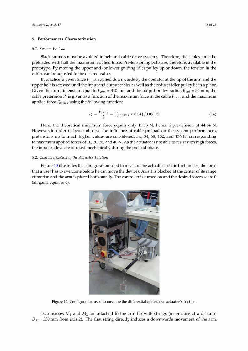
Actuators 2016, 5, 17 18 of 26
5. Performances Characterization
5.1. System Preload
Slack strands must be avoided in belt and cable drive systems. Therefore, the cables must bepreloaded with half the maximum applied force. Pre-tensioning bolts are, therefore, available in theprototype. By moving the upper and/or lower guiding idler pulley up or down, the tension in thecables can be adjusted to the desired value.
In practice, a given force Fop is applied downwards by the operator at the tip of the arm and theupper bolt is screwed until the input and output cables as well as the reducer idler pulley lie in a plane.Given the arm dimension equal to Larm = 340 mm and the output pulley radius Rout = 50 mm, thecable pretension Pc is given as a function of the maximum force in the cable Fcmax and the maximumapplied force Fopmax using the following function:
Pc “Fcmax
2“
“`
Fopmax ˆ 0.34˘
{0.05‰
{2 (14)
Here, the theoretical maximum force equals only 13.13 N, hence a pre-tension of 44.64 N.However, in order to better observe the influence of cable preload on the system performances,pretensions up to much higher values are considered, i.e., 34, 68, 102, and 136 N, correspondingto maximum applied forces of 10, 20, 30, and 40 N. As the actuator is not able to resist such high forces,the input pulleys are blocked mechanically during the preload phase.
5.2. Characterization of the Actuator Friction
Figure 10 illustrates the configuration used to measure the actuator’s static friction (i.e., the forcethat a user has to overcome before he can move the device). Axis 1 is blocked at the center of its rangeof motion and the arm is placed horizontally. The controller is turned on and the desired forces set to 0(all gains equal to 0).
Actuators 2016, 5, 17 18 of 26
In practice, a given force is applied downwards by the operator at the tip of the arm and the upper bolt is screwed until the input and output cables as well as the reducer idler pulley lie in a plane. Given the arm dimension equal to = 340 mm and the output pulley radius
= 50 mm, the cable pretension is given as a function of the maximum force in the cable and the maximum applied force using the following function: = 2 = ( × 0.34)/0.05 /2 (14)
Here, the theoretical maximum force equals only 13.13 N, hence a pre-tension of 44.64 N. However, in order to better observe the influence of cable preload on the system performances, pretensions up to much higher values are considered, i.e., 34, 68, 102, and 136 N, corresponding to maximum applied forces of 10, 20, 30, and 40 N. As the actuator is not able to resist such high forces, the input pulleys are blocked mechanically during the preload phase.
5.2. Characterization of the Actuator Friction
Figure 10 illustrates the configuration used to measure the actuator’s static friction (i.e., the force that a user has to overcome before he can move the device). Axis 1 is blocked at the center of its range of motion and the arm is placed horizontally. The controller is turned on and the desired forces set to 0 (all gains equal to 0).
Figure 10. Configuration used to measure the differential cable drive actuator’s friction.
Two masses and are attached to the arm tip with strings (in practice at a distance = 330 mm from axis 2). The first string directly induces a downwards movement of the arm. The second string is routed around a large equilibrated pulley whose friction has been previously identified. It is equal to 0.08 N for an unloaded string and 0.1 N when the string is loaded with a mass of 105 g, the pulley’s friction being supposed to vary linearly with the string load. During the measurements, , respectively , is increased (with , respectively , being kept constant)
Figure 10. Configuration used to measure the differential cable drive actuator’s friction.
Two masses M1 and M2 are attached to the arm tip with strings (in practice at a distanceDM = 330 mm from axis 2). The first string directly induces a downwards movement of the arm.
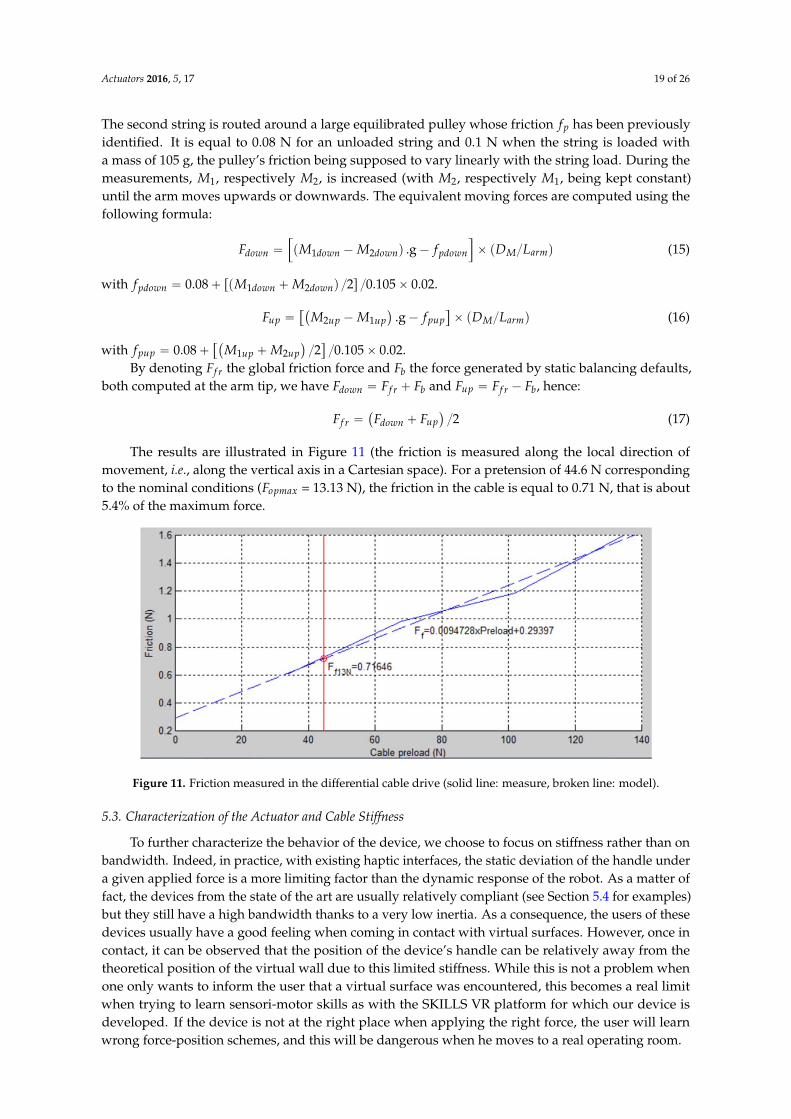
Actuators 2016, 5, 17 19 of 26
The second string is routed around a large equilibrated pulley whose friction fp has been previouslyidentified. It is equal to 0.08 N for an unloaded string and 0.1 N when the string is loaded witha mass of 105 g, the pulley’s friction being supposed to vary linearly with the string load. During themeasurements, M1, respectively M2, is increased (with M2, respectively M1, being kept constant)until the arm moves upwards or downwards. The equivalent moving forces are computed using thefollowing formula:
Fdown “”
pM1down ´M2downq .g´ fpdown
ı
ˆ pDM{Larmq (15)
with fpdown “ 0.08` rpM1down `M2downq {2s {0.105ˆ 0.02.
Fup ““`
M2up ´M1up˘
.g´ fpup‰
ˆ pDM{Larmq (16)
with fpup “ 0.08`“`
M1up `M2up˘
{2‰
{0.105ˆ 0.02.By denoting Ff r the global friction force and Fb the force generated by static balancing defaults,
both computed at the arm tip, we have Fdown “ Ff r ` Fb and Fup “ Ff r ´ Fb, hence:
Ff r “`
Fdown ` Fup˘
{2 (17)
The results are illustrated in Figure 11 (the friction is measured along the local direction ofmovement, i.e., along the vertical axis in a Cartesian space). For a pretension of 44.6 N correspondingto the nominal conditions (Fopmax = 13.13 N), the friction in the cable is equal to 0.71 N, that is about5.4% of the maximum force.
Actuators 2016, 5, 17 19 of 26
until the arm moves upwards or downwards. The equivalent moving forces are computed using the following formula: = ( − ). g − × ( / ) (15)
with = 0.08 + ( + )/2 /0.105 × 0.02. = − . g − × ( / ) (16)
with = 0.08 + + /2 /0.105 × 0.02. By denoting the global friction force and the force generated by static balancing defaults,
both computed at the arm tip, we have = + and = − , hence: = ( − )/2 (17)
The results are illustrated in Figure 11 (the friction is measured along the local direction of movement, i.e., along the vertical axis in a Cartesian space). For a pretension of 44.6 N corresponding to the nominal conditions ( = 13.13 N), the friction in the cable is equal to 0.71 N, that is about 5.4% of the maximum force.
Figure 11. Friction measured in the differential cable drive (solid line: measure, broken line: model).
5.3. Characterization of the Actuator and Cable Stiffness
To further characterize the behavior of the device, we choose to focus on stiffness rather than on bandwidth. Indeed, in practice, with existing haptic interfaces, the static deviation of the handle under a given applied force is a more limiting factor than the dynamic response of the robot. As a matter of fact, the devices from the state of the art are usually relatively compliant (see Section 5.4 for examples) but they still have a high bandwidth thanks to a very low inertia. As a consequence, the users of these devices usually have a good feeling when coming in contact with virtual surfaces. However, once in contact, it can be observed that the position of the device’s handle can be relatively away from the theoretical position of the virtual wall due to this limited stiffness. While this is not a problem when one only wants to inform the user that a virtual surface was encountered, this becomes a real limit when trying to learn sensori-motor skills as with the SKILLS VR platform for which our device is developed. If the device is not at the right place when applying the right force, the user will learn wrong force-position schemes, and this will be dangerous when he moves to a real operating room.
To characterize the response of our prototype, the actuator maximum stable static gain is adjusted for each value of the cable preload. Therefore, a fixed reference position is set and the
Figure 11. Friction measured in the differential cable drive (solid line: measure, broken line: model).
5.3. Characterization of the Actuator and Cable Stiffness
To further characterize the behavior of the device, we choose to focus on stiffness rather than onbandwidth. Indeed, in practice, with existing haptic interfaces, the static deviation of the handle undera given applied force is a more limiting factor than the dynamic response of the robot. As a matter offact, the devices from the state of the art are usually relatively compliant (see Section 5.4 for examples)but they still have a high bandwidth thanks to a very low inertia. As a consequence, the users of thesedevices usually have a good feeling when coming in contact with virtual surfaces. However, once incontact, it can be observed that the position of the device’s handle can be relatively away from thetheoretical position of the virtual wall due to this limited stiffness. While this is not a problem whenone only wants to inform the user that a virtual surface was encountered, this becomes a real limitwhen trying to learn sensori-motor skills as with the SKILLS VR platform for which our device isdeveloped. If the device is not at the right place when applying the right force, the user will learnwrong force-position schemes, and this will be dangerous when he moves to a real operating room.
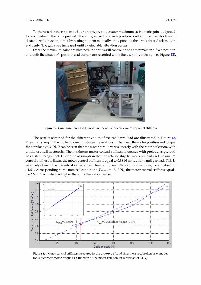
Actuators 2016, 5, 17 20 of 26
To characterize the response of our prototype, the actuator maximum stable static gain is adjustedfor each value of the cable preload. Therefore, a fixed reference position is set and the operator tries todestabilize the system, either by hitting the arm manually or by pushing the arm’s tip and releasing itsuddenly. The gains are increased until a detectable vibration occurs.
Once the maximum gains are obtained, the arm is still controlled so as to remain in a fixed positionand both the actuator’s position and current are recorded while the user moves its tip (see Figure 12).
Actuators 2016, 5, 17 20 of 26
operator tries to destabilize the system, either by hitting the arm manually or by pushing the arm’s tip and releasing it suddenly. The gains are increased until a detectable vibration occurs.
Once the maximum gains are obtained, the arm is still controlled so as to remain in a fixed position and both the actuator’s position and current are recorded while the user moves its tip (see Figure 12).
Figure 12. Configuration used to measure the actuators maximum apparent stiffness.
The results obtained for the different values of the cable pre-load are illustrated in Figure 13. The small stamp in the top left corner illustrates the relationship between the motor position and torque for a preload of 34 N. It can be seen that the motor torque varies linearly with the rotor deflection, with an almost null hysteresis. The maximum motor control stiffness increases with preload as preload has a stabilizing effect. Under the assumption that the relationship between preload and maximum control stiffness is linear, the motor control stiffness is equal to 0.38 N∙m/rad for a null preload. This is relatively close to the theoretical value of 0.49 N∙m/rad given in Table 1. Furthermore, for a preload of 44.6 N corresponding to the nominal conditions ( = 13.13 N), the motor control stiffness equals 0.62 N∙m/rad, which is higher than this theoretical value.
Figure 13. Motor control stiffness measured in the prototype (solid line: measure, broken line: model, top left corner: motor torque as a function of the motor rotation for a preload of 34 N).
Figure 12. Configuration used to measure the actuators maximum apparent stiffness.
The results obtained for the different values of the cable pre-load are illustrated in Figure 13.The small stamp in the top left corner illustrates the relationship between the motor position and torquefor a preload of 34 N. It can be seen that the motor torque varies linearly with the rotor deflection, withan almost null hysteresis. The maximum motor control stiffness increases with preload as preloadhas a stabilizing effect. Under the assumption that the relationship between preload and maximumcontrol stiffness is linear, the motor control stiffness is equal to 0.38 N¨m/rad for a null preload. This isrelatively close to the theoretical value of 0.49 N¨m/rad given in Table 1. Furthermore, for a preload of44.6 N corresponding to the nominal conditions (Fopmax = 13.13 N), the motor control stiffness equals0.62 N¨m/rad, which is higher than this theoretical value.
Figure 13. Motor control stiffness measured in the prototype (solid line: measure, broken line: model,top left corner: motor torque as a function of the motor rotation for a preload of 34 N).
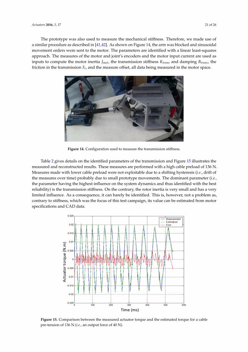
Actuators 2016, 5, 17 21 of 26
The prototype was also used to measure the mechanical stiffness. Therefore, we made use ofa similar procedure as described in [41,42]. As shown on Figure 14, the arm was blocked and sinusoidalmovement orders were sent to the motor. The parameters are identified with a linear least-squaresapproach. The measures of the motor and joint’s encoders and the motor input current are used asinputs to compute the motor inertia Jmot, the transmission stiffness Ktrans and damping Btrans, thefriction in the transmission Ft, and the measure offset, all data being measured in the motor space.
Actuators 2016, 5, 17 21 of 26
The prototype was also used to measure the mechanical stiffness. Therefore, we made use of a similar procedure as described in [41,42]. As shown on Figure 14, the arm was blocked and sinusoidal movement orders were sent to the motor. The parameters are identified with a linear least-squares approach. The measures of the motor and joint’s encoders and the motor input current are used as inputs to compute the motor inertia , the transmission stiffness and damping , the friction in the transmission , and the measure offset, all data being measured in the motor space.
Figure 14. Configuration used to measure the transmission stiffness.
Table 2 gives details on the identified parameters of the transmission and Figure 15 illustrates the measured and reconstructed results. These measures are performed with a high cable preload of 136 N. Measures made with lower cable preload were not exploitable due to a shifting hysteresis (i.e., drift of the measures over time) probably due to small prototype movements. The dominant parameter (i.e., the parameter having the highest influence on the system dynamics and thus identified with the best reliability) is the transmission stiffness. On the contrary, the rotor inertia is very small and has a very limited influence. As a consequence, it can barely be identified. This is, however, not a problem as, contrary to stiffness, which was the focus of this test campaign, its value can be estimated from motor specifications and CAD data.
Table 2. Identified parameters of the differential cable drive prototype’s transmission.
Mean value 1.5 × 10⁻⁸ Kg∙m2 0.3 N∙m/rad 2.0 × 10⁻³
N∙m/rad/s 7.0 × 10⁻³ N∙m 3.0 × 10⁻³ N∙m
Relative standard deviation 100.0% 1.0% 10.0% 2.0% 2.0%
Figure 14. Configuration used to measure the transmission stiffness.
Table 2 gives details on the identified parameters of the transmission and Figure 15 illustrates themeasured and reconstructed results. These measures are performed with a high cable preload of 136 N.Measures made with lower cable preload were not exploitable due to a shifting hysteresis (i.e., drift ofthe measures over time) probably due to small prototype movements. The dominant parameter (i.e.,the parameter having the highest influence on the system dynamics and thus identified with the bestreliability) is the transmission stiffness. On the contrary, the rotor inertia is very small and has a verylimited influence. As a consequence, it can barely be identified. This is, however, not a problem as,contrary to stiffness, which was the focus of this test campaign, its value can be estimated from motorspecifications and CAD data.Actuators 2016, 5, 17 22 of 26
Figure 15. Comparison between the measured actuator torque and the estimated torque for a cable pre-tension of 136 N (i.e., an output force of 40 N).
As the transmission stiffness for lower values of the cable pre-tension is not available with the reinforced prototype, we used data obtained with the initial non-reinforced prototype in order to have an idea of the influence of the cable pre-tension on transmission stiffness. Indeed, as highlighted in Section 4.3, two identification campaigns were performed. While the second one, from which all the results in Section 5, except here, are the results, did not allow identifying the transmission stiffness for lower cable tensions, this data is available for the first (non-reinforced) prototype. It is worth noting, however, that the transmission stiffness of this first prototype was lower than that of the reinforced one due especially to more compliant supports of the guiding pulleys (see CAD design of the first prototype in Figure 6 and reinforced prototype in Figure 9). To fit both data, we shifted the results obtained with the first prototype so that the data correspond to those of the reinforced one for a preload of 136 N, with the hypothesis that the effect of cable preload is then the same for both prototypes (i.e., the slope of the fitted line is the same).
The results are given in Figure 16. It can be seen from this picture that the cable stiffness for a preload of 44.6 N corresponding to the nominal conditions ( = 13.13 N) is only equal to 0.18 N∙m/rad. This corresponds to an apparent stiffness of 5750 N/m at the tip of the arm. This value is about the half of the theoretical value given in Table 1. All cables probably do not work in parallel as hypothetized. Still, this stiffness is relatively high compared to existing haptic interfaces.
Figure 15. Comparison between the measured actuator torque and the estimated torque for a cablepre-tension of 136 N (i.e., an output force of 40 N).
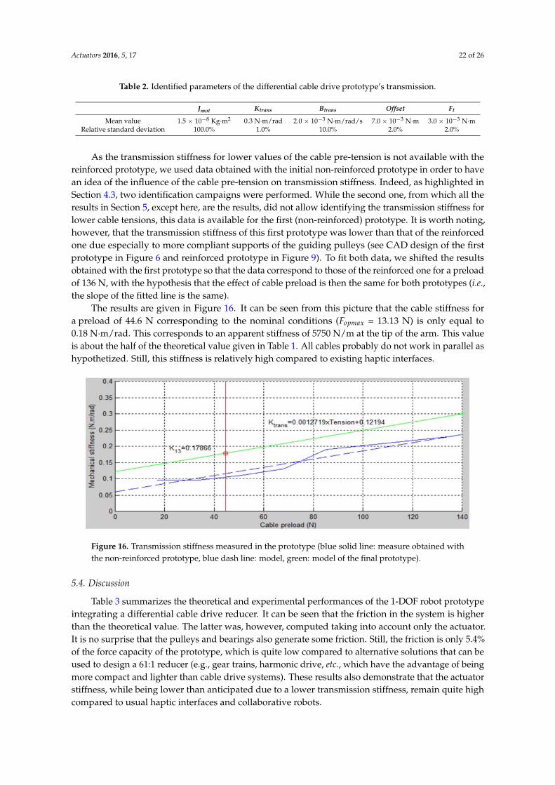
Actuators 2016, 5, 17 22 of 26
Table 2. Identified parameters of the differential cable drive prototype’s transmission.
Jmot Ktrans Btrans Offset Ft
Mean value 1.5 ˆ 10´8 Kg¨m2 0.3 N¨m/rad 2.0 ˆ 10´3 N¨m/rad/s 7.0 ˆ 10´3 N¨m 3.0 ˆ 10´3 N¨mRelative standard deviation 100.0% 1.0% 10.0% 2.0% 2.0%
As the transmission stiffness for lower values of the cable pre-tension is not available with thereinforced prototype, we used data obtained with the initial non-reinforced prototype in order to havean idea of the influence of the cable pre-tension on transmission stiffness. Indeed, as highlighted inSection 4.3, two identification campaigns were performed. While the second one, from which all theresults in Section 5, except here, are the results, did not allow identifying the transmission stiffness forlower cable tensions, this data is available for the first (non-reinforced) prototype. It is worth noting,however, that the transmission stiffness of this first prototype was lower than that of the reinforcedone due especially to more compliant supports of the guiding pulleys (see CAD design of the firstprototype in Figure 6 and reinforced prototype in Figure 9). To fit both data, we shifted the resultsobtained with the first prototype so that the data correspond to those of the reinforced one for a preloadof 136 N, with the hypothesis that the effect of cable preload is then the same for both prototypes (i.e.,the slope of the fitted line is the same).
The results are given in Figure 16. It can be seen from this picture that the cable stiffness fora preload of 44.6 N corresponding to the nominal conditions (Fopmax = 13.13 N) is only equal to0.18 N¨m/rad. This corresponds to an apparent stiffness of 5750 N/m at the tip of the arm. This valueis about the half of the theoretical value given in Table 1. All cables probably do not work in parallel ashypothetized. Still, this stiffness is relatively high compared to existing haptic interfaces.Actuators 2016, 5, 17 23 of 26
Figure 16. Transmission stiffness measured in the prototype (blue solid line: measure obtained with the non-reinforced prototype, blue dash line: model, green: model of the final prototype).
5.4. Discussion
Table 3 summarizes the theoretical and experimental performances of the 1-DOF robot prototype integrating a differential cable drive reducer. It can be seen that the friction in the system is higher than the theoretical value. The latter was, however, computed taking into account only the actuator. It is no surprise that the pulleys and bearings also generate some friction. Still, the friction is only 5.4% of the force capacity of the prototype, which is quite low compared to alternative solutions that can be used to design a 61:1 reducer (e.g., gear trains, harmonic drive, etc., which have the advantage of being more compact and lighter than cable drive systems). These results also demonstrate that the actuator stiffness, while being lower than anticipated due to a lower transmission stiffness, remain quite high compared to usual haptic interfaces and collaborative robots.
Table 3. Theoretical and experimental performances of the differential cable drive prototype.
Theoretical Performances Experimental Measurements
Actuator Level Cartesian Space Actuator Level Cartesian SpaceRange of motion 22.19 turns - - -
Max speed 5190 rpm 3.48 m/s - - Max continuous force 24.4 mN∙m 4.38 N - -
Max peak force 73.2 mN∙m 13.13 N - - Friction 0.88 mN∙m 0.16 Na - 0.71 Nb
Control stiffness 0.49 N∙m/rad 15,772 N/m 0.62 N∙m/rad 19,957 N/m Cable stiffness - 13,763 N/m 0.18 N∙m/rad 5750 N/m Robot stiffness - 7350 N/m - 4463 N/m
a Taking into account only the actuators; b Taking into account the whole system.
As a whole, these results prove that the proposed concept of a differential cable drive reducer exhibits a low friction and a high stiffness, which are the most important features of haptic interfaces (the former having in practice the highest influence on the perception of transparency in free space, the later fixing limits on the environments which can be perceived as realistic in contact). It is quite difficult to compare these results with the performances of other existing devices as their specifications in terms of force and workspace, which have a direct influence on friction and apparent stiffness, are different. Still, we can see that our prototype lies between the Sensable PHANToM Premium 1.5 and 1.5 High Force from Geomagic, which are references in the field of haptics. Indeed, they have a comparable workspace (195 mm × 270 mm × 375 mm) and the mean of their maximum force capacity (1.4 N and 8.3 N, with a mean of 4.85 N) is close to the maximum continuous force or our device (we chose here to compare the continuous force capacity of both devices, the peak force capacity being much more difficult to compare as they are not computed the same way, the Haption
Figure 16. Transmission stiffness measured in the prototype (blue solid line: measure obtained withthe non-reinforced prototype, blue dash line: model, green: model of the final prototype).
5.4. Discussion
Table 3 summarizes the theoretical and experimental performances of the 1-DOF robot prototypeintegrating a differential cable drive reducer. It can be seen that the friction in the system is higherthan the theoretical value. The latter was, however, computed taking into account only the actuator.It is no surprise that the pulleys and bearings also generate some friction. Still, the friction is only 5.4%of the force capacity of the prototype, which is quite low compared to alternative solutions that can beused to design a 61:1 reducer (e.g., gear trains, harmonic drive, etc., which have the advantage of beingmore compact and lighter than cable drive systems). These results also demonstrate that the actuatorstiffness, while being lower than anticipated due to a lower transmission stiffness, remain quite highcompared to usual haptic interfaces and collaborative robots.
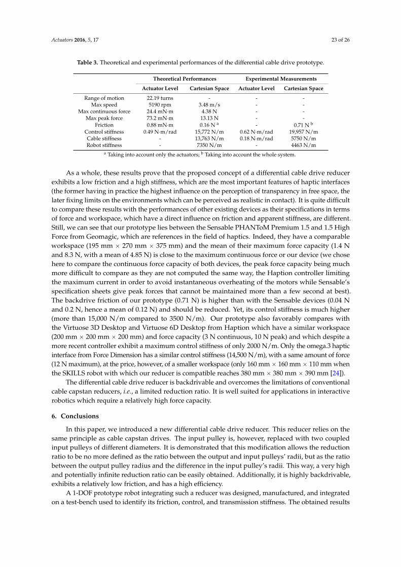
Actuators 2016, 5, 17 23 of 26
Table 3. Theoretical and experimental performances of the differential cable drive prototype.
Theoretical Performances Experimental Measurements
Actuator Level Cartesian Space Actuator Level Cartesian Space
Range of motion 22.19 turns - - -Max speed 5190 rpm 3.48 m/s - -
Max continuous force 24.4 mN¨m 4.38 N - -Max peak force 73.2 mN¨m 13.13 N - -
Friction 0.88 mN¨m 0.16 N a - 0.71 N b
Control stiffness 0.49 N¨m/rad 15,772 N/m 0.62 N¨m/rad 19,957 N/mCable stiffness - 13,763 N/m 0.18 N¨m/rad 5750 N/mRobot stiffness - 7350 N/m - 4463 N/m
a Taking into account only the actuators; b Taking into account the whole system.
As a whole, these results prove that the proposed concept of a differential cable drive reducerexhibits a low friction and a high stiffness, which are the most important features of haptic interfaces(the former having in practice the highest influence on the perception of transparency in free space, thelater fixing limits on the environments which can be perceived as realistic in contact). It is quite difficultto compare these results with the performances of other existing devices as their specifications in termsof force and workspace, which have a direct influence on friction and apparent stiffness, are different.Still, we can see that our prototype lies between the Sensable PHANToM Premium 1.5 and 1.5 HighForce from Geomagic, which are references in the field of haptics. Indeed, they have a comparableworkspace (195 mm ˆ 270 mm ˆ 375 mm) and the mean of their maximum force capacity (1.4 Nand 8.3 N, with a mean of 4.85 N) is close to the maximum continuous force or our device (we chosehere to compare the continuous force capacity of both devices, the peak force capacity being muchmore difficult to compare as they are not computed the same way, the Haption controller limitingthe maximum current in order to avoid instantaneous overheating of the motors while Sensable’sspecification sheets give peak forces that cannot be maintained more than a few second at best).The backdrive friction of our prototype (0.71 N) is higher than with the Sensable devices (0.04 Nand 0.2 N, hence a mean of 0.12 N) and should be reduced. Yet, its control stiffness is much higher(more than 15,000 N/m compared to 3500 N/m). Our prototype also favorably compares withthe Virtuose 3D Desktop and Virtuose 6D Desktop from Haption which have a similar workspace(200 mm ˆ 200 mm ˆ 200 mm) and force capacity (3 N continuous, 10 N peak) and which despite amore recent controller exhibit a maximum control stiffness of only 2000 N/m. Only the omega.3 hapticinterface from Force Dimension has a similar control stiffness (14,500 N/m), with a same amount of force(12 N maximum), at the price, however, of a smaller workspace (only 160 mmˆ 160 mmˆ 110 mm whenthe SKILLS robot with which our reducer is compatible reaches 380 mm ˆ 380 mm ˆ 390 mm [24]).
The differential cable drive reducer is backdrivable and overcomes the limitations of conventionalcable capstan reducers, i.e., a limited reduction ratio. It is well suited for applications in interactiverobotics which require a relatively high force capacity.
6. Conclusions
In this paper, we introduced a new differential cable drive reducer. This reducer relies on thesame principle as cable capstan drives. The input pulley is, however, replaced with two coupledinput pulleys of different diameters. It is demonstrated that this modification allows the reductionratio to be no more defined as the ratio between the output and input pulleys’ radii, but as the ratiobetween the output pulley radius and the difference in the input pulley’s radii. This way, a very highand potentially infinite reduction ratio can be easily obtained. Additionally, it is highly backdrivable,exhibits a relatively low friction, and has a high efficiency.
A 1-DOF prototype robot integrating such a reducer was designed, manufactured, and integratedon a test-bench used to identify its friction, control, and transmission stiffness. The obtained results

Actuators 2016, 5, 17 24 of 26
prove that the differential cable drive actuator is backdriveable, exhibits a low friction and a highstiffness. It confirms its theoretical advantages.
The proposed differential cable drive actuator is well suited for applications in interactive roboticswhich require a relatively high force capacity.
Acknowledgments: This work was partially supported by the European Commission (SKILLS Integrated Project,IST-FP6 #035005).
Author Contributions: Florian Gosselin initiated and supervised the development of the differential cable driveactuator and wrote the paper, Fabien Ferlay performed the dimensioning, design, assembly and integration of theprototype, Alexandre Janot performed the system’s performances identification.
Conflicts of Interest: The authors declare no conflict of interest.
References
1. Worldwide Distribution of Industrial Robots. In World Robotics, Industrial Robots; International Federation ofRobotics Statistical Department: Frankfurt, Germany, 2013; pp. 42–94.
2. Peshkin, M.A.; Colgate, J.E.; Wannasuphroprasit, W.; Moore, C.A.; Gillespie, R.B.; Akella, P.Cobot Architecture. IEEE Trans. Robot. Autom. 2001, 17, 377–390. [CrossRef]
3. Colgate, J.E.; Peshkin, M.; Klostermeyer, S.H. Intelligent Assist Devices in Industrial Applications: A Review.In Proceedings of the IEEE International Conference on Intelligent Robots and Systems, Las Vegas, NV, USA,27–31 October 2013; Volume 3, pp. 2516–2521.
4. Lamy, X.; Colledani, F.; Geffard, F.; Méasson, Y.; Morel, G. Achieving efficient and stable comanipulationthrough adaptation to changes in human arm impedance. In Proceedings of the IEEE InternationalConference on Robotics and Automation, Kobe, Japan, 12–17 May 2009; pp. 265–271.
5. Townsend, W.T. The Effect of Transmission Design on Force-controlled Manipulator Performance.Ph.D Thesis, Massachussets Institute of Technology, Cambridge, MA, USA, 1998.
6. Bischoff, R.; Kurth, J.; Schreiber, G.; Koeppe, R.; Albu-Schäffer, A.; Beyer, A.; Eiberger, O.; Haddadin, S.;Stemmer, A.; Grunwald, G.; et al. The KUKA-DLR lightweight robot arm—A new reference platform forrobotics research and manufacturing. In Proceedings of the International Symposium on Robotics (ISR),Munich, Germany, 7–9 June 2010; pp. 1–8.
7. Riwan, A.; Giudicelli, B.; Taha, F.; Lazennec, J.-Y.; Sabhani, A.; Kilian, P.; Jabbour, Z.; VanRhijn, J.; Louveau, F.;Morel, G.; et al. Projet Surgicobot: Robot d’assistance à la chirurgie du rachis. IRBM 2011, 32, 130–134.[CrossRef]
8. Kazerooni, H. Exoskeletons for Human Performance Augmentation. In Springer Handbook of Robotics;Siciliano, B., Khatib, O., Eds.; Springer: New York, NY, USA, 2008; pp. 773–793.
9. Sylla, N.; Bonnet, V.; Colledani, F.; Fraisse, P. Ergonomic contribution of ABLE exoskeleton in automotiveindustry. Int. J. Ind. Ergon. 2014, 44, 475–481. [CrossRef]
10. Fontana, M.; Vertechy, R.; Marcheschi, S.; Salsedo, F.; Bergamasco, M. The Body Extender, A Full-BodyExoskeleton for the Transport and Handling of Heavy Loads. IEEE Robot. Autom. Mag. 2014, 21, 34–44.[CrossRef]
11. Billard, A.; Calinon, S.; Dillmann, R.; Schaal, S. Robot Programming by Demonstration. In Springer Handbookof Robotics; Siciliano, B., Khatib, O., Eds.; Springer: New York, NY, USA, 2008; pp. 1371–1394.
12. Robotiq. Collaborative Robot EBook, 5th ed.; Robotiq: Lévis, QC, Canada, 2014.13. Vertut, J.; Coiffet, P. Les robots—Tome 3A: téléopération, évolution des technologies; Hermes Publishing: Paris,
France, 1984. (In French)14. Sheridan, T.B. Telerobotics. Automatica 1989, 25, 487–507. [CrossRef]15. Hokayem, P.F.; Spong, M.W. Bilateral teleoperation: An historical survey. Automatica 2006, 42, 2035–2057.
[CrossRef]16. Massie, T.H.; Salisbury, J.K. The PHANToM haptic interface: A device for probing virtual objects.
In Proceedings of the ASME Haptic Interfaces for Virtual Environment and Teleoperator Systems in DynamicSystems and Control, Chicago, IL, USA, 6–11 November 1994; pp. 295–301.
17. Hayward, V.; Astley, O.R.; Cruz-Hernandez, M.; Grant, D.; Robles-De-La-Torre, D. Haptic interfaces anddevices. Sens. Rev. 2004, 24, 16–29. [CrossRef]

Actuators 2016, 5, 17 25 of 26
18. Gosselin, F.; Andriot, C.; Fuchs, P. Hardware Devices of Force Feedback Interfaces. In Virtual Reality: Conceptsand Technologies; Fuchs, P., Moreau, G., Guitton, P., Eds.; CRC Press/Balkema: Leiden, The Netherlands, 2011;Chapter 8; pp. 137–178.
19. Vertut, J.; Charles, J.; Coiffet, P.; Petit, M. Advance of the MA23 force reflecting manipulator system.In Proceedings of the Symposium on the Theory and Practice of Robots and Manipulators, Warsaw, Poland,14–17 September 1976.
20. Bejczy, A.K. Teleoperation: The Language of the Human Hand. In Proceedings of the IEEE InternationalWorkshop on Robot and Human Communication, Tokyo, Japan, 1–3 September 1992; pp. 32–43.
21. McAffee, D.A.; Snow, E.R.; Townsend, W.T. Force Reflecting Hand Controller. U.S. Patent No. 5,193,963, 16March 1993.
22. Madhani, A.J. Design of Teleoperated Surgical Instruments for Minimally Invasive Surgery. Ph.D Thesis,Massachusetts Institute of Technology, Cambridge, MA, USA, 1998.
23. Gosselin, F.; Bidard, C.; Brisset, J. Design of a high fidelity haptic device for telesurgery. In Proceedings ofthe 2005 IEEE International Conference on Robotics and Automation, Barcelona, Spain, 18–22 April 2005;pp. 206–211.
24. Gosselin, F.; Ferlay, F.; Bouchigny, S.; Mégard, C.; Taha, F. Specification and design of a new haptic interfacefor maxillo facial surgery. In Proceedings of the 2011 IEEE International Conference on Robotics andAutomation, Shanghai, China, 9–13 May 2011; pp. 737–744.
25. Cai, V.A.D.; Bidaud, P.; Hayward, V.; Gosselin, F.; Desailly, E. Self-Adjusting, Isostatic Exoskeleton for theHuman Knee Joint. In Proceedings of the Annual International Conference of the IEEE Engineering inMedecine and Biology Society, Boston, MA, USA, 30 August–3 September 2011; pp. 612–618.
26. Ramos, J.; Wang, A.; Kim, S. A Balance Feedback Human Machine Interface for Humanoid Teleoperation inDynamic Tasks. In Proceedings of the IEEE/RSJ International Conference on Intelligent Robots and Systems,Hamburg, Germany, 28 September–2 October 2015; pp. 4229–4235.
27. Garrec, P. Screw and Cable Acutators (SCS) and Their Applications to Force Feedback Teleoperation,Exoskeleton and Anthropomorphic Robotics. In Robotics 2010: Current and Future Challenges; Abdellatif, H.,Ed.; Intech: Rijeka, Croatia, 2010; pp. 167–191.
28. Geffard, F.; Andriot, C.; Micaelli, A.; Morel, G. On the Use of a Base Force/Torque Sensor in Teleoperation.In Proceedings of the IEEE International Conference on Robotics and Automation, San Francisco, CA, USA,24–28 April 2000; pp. 2677–2683.
29. Geffard, F.; Garrec, P.; Piolain, G.; Brudieu, M.-A.; Thro, J.-F.; Coudray, A.; Lelann, E. TAO2000 V2Computer-Assisted Force Feedback Telemanipulators Used as Maintenance and Production Tools at theAREVA NC–La Hague Fuel Recycling Plant. J. Field Robot. 2012, 29, 161–174. [CrossRef]
30. Lamy, X. Conception d’une interface de pilotage d’un cobot. Ph.D Thesis, Université Pierre et Marie Curie,Paris, France, 2011. (In French)
31. Hirzinger, G.; Sporer, N.; Schedl, M.; Butterfaß, J.; Grebenstein, M. Torque-Controlled Lightweight Arms andArticulated Hands: Do We Reach Technological Limits Now? Int. J. Robot. Res. 2004, 23, 331–340. [CrossRef]
32. Haddadin, S.; Albu-Shäffer, A.; Hirzinger, G. Requirements for Safe Robots: Measurements, Analysis andNew Insights. Int. J. Robot. Res. 2009, 28, 1507–1527. [CrossRef]
33. Hulin, T.; Hertkorn, K.; Kremer, P.; Schatzle, S.; Artigas, J.; Sagardia, M.; Zacharias, F.; Preusche, C. The DLRBimanual Haptic Device with Optimized Workspace. In Proceedings of the IEEE International Conferenceon Robotics and Automation, Shangai, China, 9–13 May 2011; pp. 3441–3442.
34. Pratt, G.A.; Williamson, M.M. Series elastic actuators. In Proceedings of the IEEE/RSJ InternationalConference on Intelligent Robots and Systems, Pittsburgh, PA, USA, 5–9 August 1995; pp. 399–406.
35. Grebenstein, M.; Albu-Schaffer, A.; Bahls, T.; Chalon, M.; Eiberger, O.; Friedl, W.; Gruber, R.; Haddadin, S.;Hagn, U.; Haslinger, R.; et al. The DLR Hand Arm System. In Proceedings of the IEEE InternationalConference on Robotics and Automation, Shangai, China, 9–13 May 2011; pp. 3175–3182.
36. Andriot, C.; Gosselin, F.; Fuchs, P. Control of a Force Feedback Interface. In Virtual Reality: Concepts andTechnologies; Fuchs, P., Moreau, G., Guitton, P., Eds.; CRC Press/Balkema: Leiden, The Netherlands, 2011;Chapter 9; pp. 179–190.
37. Gil, J.J.; Sanchez, E.; Hulin, T.; Preusche, C.; Hirzinger, G. Stability boundary for haptic rendering: influenceof damping and delay. J. Comput. Inf. Sci. Eng. 2009, 9, 011005:1–011005:8. [CrossRef]

Actuators 2016, 5, 17 26 of 26
38. Gosselin, F.; Ferlay, F. Dossier de conception d’un réducteur différentiel pour le Virtuose 6D médical évolution II;Internal Report DTSI/SRCI/08–536; CEA LIST: Fontenay-aux-Roses, France, 2008. (In French)
39. Gosselin, F.; Bouchigny, S.; Mégard, C.; Taha, F.; Delcampe, P.; D’Hauthuille, C. Haptic systems for trainingsensori-motor skills, a use case in surgery. Robot. Auton. Syst. 2013, 61, 380–389. [CrossRef]
40. Marx, N.; Alexandre, J.M.; Pottier, P. Métrologie et mise en œuvre d’un variateur pour moteur à courant continu;Internal Report DTSI/SRSI/LEMS/02RT.037; CEA LIST: Fontenay-aux-Roses, France, 2002. (In French)
41. Janot, A.; Bidard, C.; Gosselin, F.; Gautier, M.; Keller, D.; Perrot, Y. Modeling and identification of a 3 DOFhaptic interface. In Proceedings of the IEEE International Conference on Robotics and Automation, Roma,Italy, 10–14 April 2007; pp. 4949–4955.
42. Janot, A.; Gautier, M.; Jubien, A.; Vandanjon, P.O. Experimental joint stiffness identification depending onmeasurements availability. In Proceedings of the IEEE Conference on Decision and Control and EuropeanControl Conference, Orlando, FL, USA, 12–15 December 2011; pp. 5112–5117.
© 2016 by the authors; licensee MDPI, Basel, Switzerland. This article is an open accessarticle distributed under the terms and conditions of the Creative Commons Attribution(CC-BY) license (http://creativecommons.org/licenses/by/4.0/).
Related Documents


![Design of Robust and Force Sensitive Actuator for …Abstract Model of Backdrivable Actuators • Series Elastic Actuator J 1 J 2 K=[k ij] J 1 J 2 D=[d ij] •Electro‐Hydrostatic](https://static.cupdf.com/doc/110x72/5eb646a14e8f5d0b3741a88f/design-of-robust-and-force-sensitive-actuator-for-abstract-model-of-backdrivable.jpg)