This paper appears in Smart Materials and Structures 2013 doi:10.1088/0964-1726/23/2/025028 http://www.iopscience.iop.org/0964-1726/23/2/025028/ 1 Development of a multilayered wide-ranged torque magnetorheological brake Carlos Rossa, Adrien Jaegy, Alain Micaelli, and Jos´ e Lozada Abstract—This paper presents the design of a multilayered magnetorheological brake from modelling to prototyping and characterisation. A magnetostatic model intended to provide a specific magnetic flux density over a fluid gap regardless of the dimensions of the fluid surface is proposed. The ferromagnetic path and the coil are dimensioned in consequence. The model needs only three inputs to completely define the brake i.e. the number of fluid gaps, the inner radius of the smallest fluid gap and the fluid gap depth. The evaluation criteria are defined by the torque density, the controllability and the reactivity, described as a function of the dimensions and the number of fluid gaps. The model has been optimized to improve the torque density. The brake has 4 fluid gaps and has been built and characterized. The expected torque when the fluid reaches the desired induction is 3.4 Nm and the measured torque is 3.6 Nm. This represents a relative error of 5.5%. The brake has 60 mm diameter, 39 mm width with a hollow shaft of 12 mm diameter. When exploited up to complete saturation, the measured torque is 5.3 Nm with 19 W power consumption. The brake has a torque density of 48.1 kN/m 2 , a maximum-to-minimum torque ratio of 176 with 50 ms electromechanical time constant. I. I NTRODUCTION Rheological fluids have been successfully applied in a wide range of high fidelity actuators within the context of human- machine interfaces during the past two decades. Such devices provide fast response time, high force per volume ratio with low power requirements, making them particularly suitable for the design of embedded systems [18]. A rheological fluid consists of a suspension of micron- sized soft ferromagnetic or non-conducting particles dispersed in a carrying liquid (typically mineral oils, synthetic oils or water). Their rheological properties can be instantly, strongly and reversibly modified by the action of an electric field, in the case of a electrorheological fluid (ERF) [4], or by the action of a magnetic field in the case of a magnetorheological fluid (MRF) [13]. While ERF-based actuators typically need excitation voltages in the range of a kilovolt, MRF-based actuators need relatively low operating currents and voltages. Designing an MRF actuator implies dealing with non- linearities introduced by the fluid behaviour and the magnetic saturation. Furthermore, a tradeoff can be observed between the measures of performance characterizing an MRF actuator. For human friendly robotics applications, the actuator can be evaluated with regards to the torque density, controllability and reactivity. Torque density ρ is the ratio torque-to-volume in terms of N/m 2 , the controllability K is the maximum torque The authors are with the French Atomic Energy Commission, CEA, LIST Sensorial and Ambient Interfaces Laboratory 91191 Gif-sur-Yvette, France. Email: [email protected]; [email protected]; [email protected] to minimum torque ratio, and the reactivity δ t is the torque- to-eletric time constant ratio in terms of Nm/s measured for a step-type excitation. Most of the available work dealing with the design and optimization of MRF actuators predominantly focusses on torque optimization. For instance, Karakoc et al. [7] present the design of an automotive MRF brake using a multiphysics optimization method to maximize the controllable torque. A cost function is defined including the braking torque and weight. In the same way, using finite element analysis, Park et al. [16] define cost functions to maximize to the torque-to- weight ratio while keeping a minimal required braking torque. Gudmundsson et al. [5] present a multi-objective optimization method for a prosthetic knee brake in terms of controllable torque, including also the off-state torque and weight. They consider an optimization parameter as a constraint in the modelling, or as an additional objective function. Zhang et al. [24] focus on a finite element analysis of the magnetic circuit saturation of an MRF-based damper. Yang et al. [23] investigate the feasibility of an MRF valve considering the relation of the volume fraction to yield stress, response time of the coils and electric power losses. Nguyen et al. [14] present an optimized design of a motorcycle brake where the required braking torque, temperature, mass and geometric dimensions are defined as optimization constraints. In some approaches, the goal of the optimization is to increase the magnetic flux in the MRF as much as possible [1]. However, the necessary coil volume and power supply increase considerably if the fluid becomes saturated. With regards to the considered evaluation criteria, a com- mercially available MRF-brake (RD-2078-01) from Lord Cor- poration [2] has 96.6 mm diameter, 35.7 mm width and generates from 0.4 Nm (off-state torque) to 4 Nm at 1 A. The response time is 10 ms, yielding a torque density of 12.5 kN/m 2 , a controllability of 10, and a reactivity of 400 Nm/s. Liu et al. [11] discus the conception of a single disc MRF brake able to provide 0.5 to 7 Nm at 2 A, or rather a torque density of 17.4 kN/m 2 , and a dynamic range of 14. Guo and Liao [6] present the optimization of a clutch/brake system and obtain a torque density of 13.6 kN/m 2 , and a reactivity ratio of 19.2 Nm/s. Senkal and Gurocak [22] present the design of a 10.9 Nm serpentine flux path-based brake with low friction sealing technique in order to reduce off-state torque. The authors present a o torque density of 38.4 kN/m 2 , a controllability of 109, and a reactivity of 181.2 Nm/s. This paper presents the design of a high torque density MRF brake from analytical modelling to prototyping and characterisation. A magnetostatic model intended to deliver a desired magnetic flux density over the fluid surface is

Welcome message from author
This document is posted to help you gain knowledge. Please leave a comment to let me know what you think about it! Share it to your friends and learn new things together.
Transcript
This paper appears in Smart Materials and Structures 2013doi:10.1088/0964-1726/23/2/025028
http://www.iopscience.iop.org/0964-1726/23/2/025028/
1
Development of a multilayered wide-rangedtorque magnetorheological brakeCarlos Rossa, Adrien Jaegy, Alain Micaelli, and Jose Lozada
Abstract—This paper presents the design of a multilayeredmagnetorheological brake from modelling to prototyping andcharacterisation. A magnetostatic model intended to provide aspecific magnetic flux density over a fluid gap regardless of thedimensions of the fluid surface is proposed. The ferromagneticpath and the coil are dimensioned in consequence. The modelneeds only three inputs to completely define the brake i.e. thenumber of fluid gaps, the inner radius of the smallest fluid gapand the fluid gap depth. The evaluation criteria are defined bythe torque density, the controllability and the reactivity, describedas a function of the dimensions and the number of fluid gaps.The model has been optimized to improve the torque density. Thebrake has 4 fluid gaps and has been built and characterized. Theexpected torque when the fluid reaches the desired induction is3.4 Nm and the measured torque is 3.6 Nm. This represents arelative error of 5.5%. The brake has 60 mm diameter, 39 mmwidth with a hollow shaft of 12 mm diameter. When exploited upto complete saturation, the measured torque is 5.3 Nm with 19W power consumption. The brake has a torque density of 48.1kN/m2, a maximum-to-minimum torque ratio of 176 with 50 mselectromechanical time constant.
I. INTRODUCTION
Rheological fluids have been successfully applied in a widerange of high fidelity actuators within the context of human-machine interfaces during the past two decades. Such devicesprovide fast response time, high force per volume ratio withlow power requirements, making them particularly suitable forthe design of embedded systems [18].
A rheological fluid consists of a suspension of micron-sized soft ferromagnetic or non-conducting particles dispersedin a carrying liquid (typically mineral oils, synthetic oils orwater). Their rheological properties can be instantly, stronglyand reversibly modified by the action of an electric field, inthe case of a electrorheological fluid (ERF) [4], or by theaction of a magnetic field in the case of a magnetorheologicalfluid (MRF) [13]. While ERF-based actuators typically needexcitation voltages in the range of a kilovolt, MRF-basedactuators need relatively low operating currents and voltages.
Designing an MRF actuator implies dealing with non-linearities introduced by the fluid behaviour and the magneticsaturation. Furthermore, a tradeoff can be observed betweenthe measures of performance characterizing an MRF actuator.For human friendly robotics applications, the actuator can beevaluated with regards to the torque density, controllabilityand reactivity. Torque density ρ is the ratio torque-to-volumein terms of N/m2, the controllability K is the maximum torque
The authors are with the French Atomic Energy Commission, CEA, LISTSensorial and Ambient Interfaces Laboratory 91191 Gif-sur-Yvette, France.Email: [email protected]; [email protected]; [email protected]
to minimum torque ratio, and the reactivity δ t is the torque-to-eletric time constant ratio in terms of Nm/s measured for astep-type excitation.
Most of the available work dealing with the design andoptimization of MRF actuators predominantly focusses ontorque optimization. For instance, Karakoc et al. [7] presentthe design of an automotive MRF brake using a multiphysicsoptimization method to maximize the controllable torque. Acost function is defined including the braking torque andweight. In the same way, using finite element analysis, Parket al. [16] define cost functions to maximize to the torque-to-weight ratio while keeping a minimal required braking torque.Gudmundsson et al. [5] present a multi-objective optimizationmethod for a prosthetic knee brake in terms of controllabletorque, including also the off-state torque and weight. Theyconsider an optimization parameter as a constraint in themodelling, or as an additional objective function. Zhang etal. [24] focus on a finite element analysis of the magneticcircuit saturation of an MRF-based damper. Yang et al. [23]investigate the feasibility of an MRF valve considering therelation of the volume fraction to yield stress, response time ofthe coils and electric power losses. Nguyen et al. [14] presentan optimized design of a motorcycle brake where the requiredbraking torque, temperature, mass and geometric dimensionsare defined as optimization constraints. In some approaches,the goal of the optimization is to increase the magnetic fluxin the MRF as much as possible [1]. However, the necessarycoil volume and power supply increase considerably if thefluid becomes saturated.
With regards to the considered evaluation criteria, a com-mercially available MRF-brake (RD-2078-01) from Lord Cor-poration [2] has 96.6 mm diameter, 35.7 mm width andgenerates from 0.4 Nm (off-state torque) to 4 Nm at 1 A.The response time is 10 ms, yielding a torque density of12.5 kN/m2, a controllability of 10, and a reactivity of 400Nm/s. Liu et al. [11] discus the conception of a single discMRF brake able to provide 0.5 to 7 Nm at 2 A, or rather atorque density of 17.4 kN/m2, and a dynamic range of 14.Guo and Liao [6] present the optimization of a clutch/brakesystem and obtain a torque density of 13.6 kN/m2, and areactivity ratio of 19.2 Nm/s. Senkal and Gurocak [22] presentthe design of a 10.9 Nm serpentine flux path-based brakewith low friction sealing technique in order to reduce off-statetorque. The authors present a o torque density of 38.4 kN/m2,a controllability of 109, and a reactivity of 181.2 Nm/s.
This paper presents the design of a high torque densityMRF brake from analytical modelling to prototyping andcharacterisation. A magnetostatic model intended to delivera desired magnetic flux density over the fluid surface is
2
(a) (b) (c) (d)
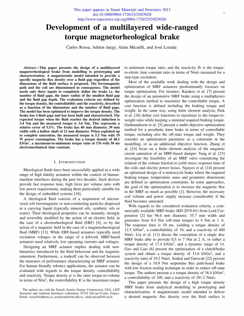
Fig. 1. Rheological effect in an MRF suspension between shearing plates. Theparticles are homogeneously distributed in the carrier liquid (a). A magneticfield ~H is applied and magnetizes the particles which behave as a magneticdipole and undergo interaction forces (b) before forming chain-like structuresaligned to the field (c). A relative displacement of the poles stretches thechains and create a resistive force ~F against the velocity x (d). The resistiveforce increases with the magnitude of the applied magnetic field.
developed. The model allows for an optimal design of theferromagnetic path and the coil taking into consideration themagnetic saturation. It also defines the mentioned evaluationcriteria as a function of the dimensions and the number of fluidgaps. The design requirements are: a desired torque of 3.2 Nm,an external radius inferior to 30 mm and a 6 mm radius hollowshaft. The paper is organized as follows. Section II presents abrief review of the MRF behaviour. The brake geometry andits respective magnetostatic model are subsequently presentedand the evaluation criteria are defined. In Section III, the linearrange of the analytical model is verified using finite elementanalysis. The results highlight that the evaluation criteria areinterconnected and a compromise between torque density andcontrollability must be found. The optimized brake has beenbuilt and the experimental results are presented in Section IV.The final dimensions are 60 mm diameter, 39 mm width witha hollow shaft of 12 mm diameter. The torque varies from0.03 Nm to 5.3 Nm and the brake consumes 19 W. This givesa torque density of 48.1 kN/m2, a controllability of 176.6 anda reactivity ratio of 106 Nm/s.
II. ANALYTICAL MODELLING
In this section the analytical model based on the Binghamplastic formulation is developed. The model defines the eval-uation criteria as a function of the dimensions and the numberof fluid gaps.
A. Rheological Behaviour
Fig. 1 shows the rheological effect in an MR suspension andhow this principle can be employed for the design of MRF-based actuators. The fluid is commonly confined between twomagnetic poles. In the absence of a magnetic field, the particlesof the MR suspension are homogeneously distributed in thecarrier fluid and the suspension behaves as a Newtonian fluidFig.1(a). When a magnetic field ~H is applied, the particles aremagnetized and undergo magnetic interaction forces Fig.1(b).Hence, they form chain-like structures or aggregates alignedroughly parallel to the applied field Fig.1(c). The chain struc-tures create a mechanical resistance against the relative motionof the poles or against a fluid flow. This phenomenon ismacroscopically perceived as an almost instantaneous alter-ation of the fluid’s apparent viscosity. When the mangetic polesare displaced, a resistive force appears on the poles passing
coil
stationary housing
rotary shaft
MR fluid
coil
rotary shaft
MR fluid
stationary housing
(a) (b)
Fig. 2. Single disc (a) and single cylinder (b) based brakes. The disc brakeis composed of a thin fluid gap perpendicular to the rotation axis. In thecylindrical brake the fluid is in a cylindrical volume around the axis. Themagnetic flux Φ is provided by a coil.
through them, slowing or stopping their relative displacementFig.1(d). This phenomenon can be exploited to the design ofcontrollable brakes.
The Bingham model [10] is commonly used to describe thebehaviour of MRFs as a function of the magnetic field H. Thefluid shear stress τ(γ,H) delivered by the fluid is consideredas a contribution of both a field dependent yield stress τy(H)and a viscous friction, which is dependent on the shear stressrate γ and the fluid viscosity η . The Bingham formulationgives:
|τ(γ,H)|= τy(H)+η |γ| i f |τ(γ,H)|> τy(H) (1)γ = 0 otherwise (2)
By setting the magnetic field strength, the fluid can displaya controllable yield stress.
B. Magnetostatic and Mechanical Modelling
The shear operating mode of an MRFs is commonly utilisedin rotary brakes. These actuators commonly take the form ofa disc or a cylindrical housing as illustrated in Fig. 2. Themagnetic flux Φ is applied orthogonally against the fluid shear.For disc brakes (Fig 2(a)), the fluid is confined in a thin volumeplaced perpendicular to the rotation axis while in the caseof a cylindrical brake (Fig 2(b)), the fluid is in a cylindricalgap around the axis of rotation. The magnetic field is usuallyprovided by coils. Thereby the resistive torque generated bythe brake can be controlled by setting the coil current strength.
According to the Bingham model, an MRF brake displaysa controllable torque Th, which is a function of the fielddependent yield stress, and a viscous torque Tv proportionalto the relative velocity of the poles. The total braking torqueis Tb = Th +Tv.
In order to maximize the torque in a given volume, theassociation of many elementary discs or cylinders in parallelis an efficient way for achieving high levels of torque aspresented in [5][15][17]. While in a multiple disc brake therelation between the number of discs and the torque is linear,the torque displayed by a multiple cylinder increases with thesquare of the radius of each cylinder.
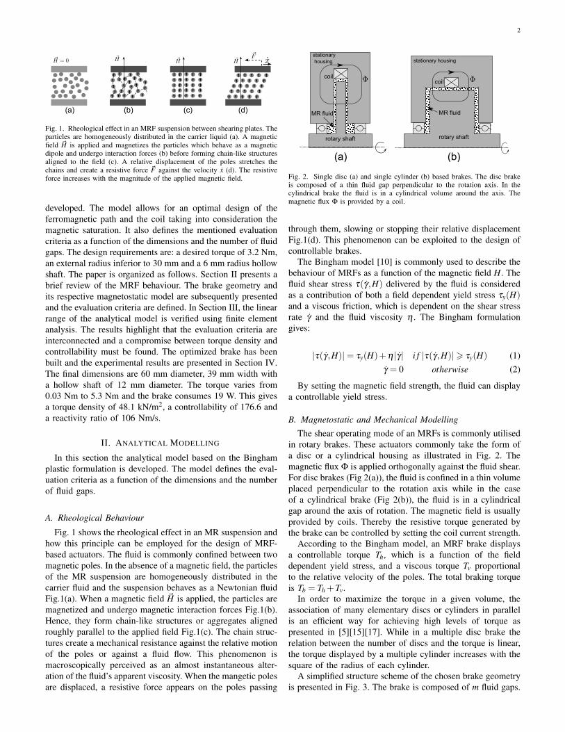
A simplified structure scheme of the chosen brake geometryis presented in Fig. 3. The brake is composed of m fluid gaps.
3
rotary shaft
MR fluid
coil
seal andbearing
stationary ferromagnetic
housing
Fig. 3. Multilayered cylindrical brake with 4 fluid gaps: The external lengthand radius are Lt and Rt . Each cylinder separated by a gap g has a thickness eand a radius rk . The radius of the smallest fluid gap is called r and the radiusof the largest one is r4 = R. L is the gap length, b the height of the coil andq the width of the ferromagnetic path on the right side of the coil, in-wherethe magnetic flux Φ loops. The width of the ferromagnetic section under thegaps is denoted p and of the lateral supports is z. The shaft rotates accordingto a velocity ω . The coil is reported laterally to the cylinders to reduce theelectric consumption.
The total radius and length are Rt and Lt respectively. Wedenote g the fluid gap depth, e the thickness of each cylinder,rk the inner radius of the fluid gap k, so that 1≤ k ≤ m withk ∈N∗, with rm = R and r1 = r the inner radius of the largestand of the smallest fluid surface respectively, b the coil width,q the width of the ferromagnetic path on the right side ofthe coil, and p the ferromagnetic path width below the gaps.The coil is placed adjacent to gaps in order to maximize thefluid surface crossed by the magnetic flux and to minimize itselectric resistance.
The magnetic flux Φ(t) generated by a coil with N turnsof wire excited by a current i(t) is given by Φ(t) = Ni(t)/R,where R is the magnetic reluctance observed by the coil. Theinner surface Sk of each fluid gap is Sk = 2πLrk with L thecylinder length and rk+1 = rk + e+ g. Considering only thereluctance of a fluid with an absolute permeability µmr, thereluctance is computed as follows:
R =1
2πµmrL
R∫r
drr
= gln[1+m(e+g)r−1
]2πµmrL(g+ e)
(3)
Considering that the permeability of the fluid is constant,a linear relationship between the magnetic field H(t) and themagnetic flux density can be established as B(t) = µmrH(t).The induced magnetic field over the fluid surface is H(t) =Ni(t)/µmrSR under assumption of a homogeneous flux on thefluid gap and non-saturation of the ferromagnetic circuit.
Regardless of the given geometry, the tangential resistiveforce is calculated by integrating τ(γ,H) over the shearingsurface S. For a rotary device, taking into account the radius rkbetween this surface and the rotation axis, the braking torqueTb for m fluid gaps is the given by the sum of the torquedelivered by each fluid surfaces as:
Tb =m
∑k=1
∫ ∫rkτ(H, γ)dS (4)
The relationship between the magnetic field H(t) andthe fluid dependent yield stress τy(H) is typically denotedτy(H) =αH(t)β [9] where α and β are fluid constants. Beforethe saturation point of the fluid we consider β = 1. Usingthe Bingham plastic model integrated over each fluid surfacecombined to Equation 4, the total torque Tb is:
Tb =Nα
Rµmri(t)
m
∑k=1
rk +2πηLg
ω(t)m
∑k=1
r3k (5)
With ω(t) the rotational velocity and η the fluid viscosity.In equation 5, the first term corresponds to the field dependenttorque Th and the second to the viscous torque Tv. The fluid gaplength L is taken into consideration in the magnetic reluctance.The controllable torque can be rewritten as a function of thenumber of fluid gaps m and as a function of a desired magneticflux density over the smallest fluid surface S1 called Bd , as:
Th = 2πr2Lα
µmr
[m+
(m−1)(R− r)2r
]Bd (6)
This equation suggests that the controllable torque increaseswith the number of fluid gaps. The viscous torque Tv isobtained as the sum of the viscous torque of each cylinderand can be approximated by:
Tv = 2πηLr3
gm[
1+32
(e+g
r
)(m−1)
]ω(t) (7)
The viscous torque quadratically increases with the numberof fluid gaps.
The required flux to obtain the desired magnetic flux densityBd over the smallest fluid surface S1 is Φ = BdS1. This definesthe magneto-motive force Nimax, given by:
Nimax = BdS1R (8)
where imax is the necessary current to achieve Bd with Nwire turns. The magnetomotive force then defines the powersupply P. The power can be obtained by Joule’s losses asP = i2maxRe where Re is the electric resistance of the coil. Theresistance expressed as a function of the resistivity of the wireκ , the mean radius of the coil rb and the section of the wire Sw,is Re = 2πrbκN/Sw. The section of the wire can be refereedto the desired maximum current-to-surface ratio ν in term ofA/m2 so that imax = Swν .
Replacing the current and the resistivity of the wire inthe Joule’s equation, the power can be rewritten as P =2πrbκνNimax. Combining this equation with Equations 8 and3, the power can be given as a function of the number of fluidgaps and the desired magnetic flux density on the smallestfluid by:
P = πνκ
µmrg
rbre+g
ln[
1+m(e+g)
r
]Bd (9)
The power consumption increases with the number of fluidgaps and is dependent on the fluid gap depth.
The eletric time constant of the coil is a function of themagnetic reluctance [8]. Considering the coil as an LR circuit,the time constant is given by δ tc = Lin/Re where Lin is the
4
inductance of the coil calculated as Lin = N2/R. The eletrictime constant yields:
δ tc =N2
ReR=
BdS1
2πκνrb= 2
rLκν(R+ r)
Bd (10)
According to this equation, as R = r +(e+ g)m the elec-tric time constant decreases with the number of fluid gaps.Knowing the power supply and the magnetic flux, the othergeometrical dimensions of the brake can now be calculated.
The coil volume can be expresses as Vcoil = 2πrbSwN/χ
where χ is the coil fill rate or as a function of the powersupply as Vcoil = P/κν2χ . Considering that the inner and theexternal radius of the coil are r and R respectively, the coilwidth b can be computed as b = P/π(R2−r2)ν2κχ , or rather:
b =g(R− r)
µmrνχ(e+g)(R2−3r2)ln[
1+m(e+g)
r
]Bd (11)
The magnetic path must be dimensioned in order to supportthe magnetic flux Φ = BdS1. A minimal ferromagnetic pathsection is therefore necessary to avoid the saturation of thepath. Consider B f er the maximal admissible magnetic fluxdensity of the ferromagnetic path and Sn the ferromagneticsection crossed by the flux. The flux conservation givesthe relation BdS1 = B f erSn under the assumption of no fluxleakages.
The minimal external radius to obtain the necessary crosssection width on the top of the coil Rt − R, then is Rt =√
2rLcsat +R2 whit csat = Bd/B f er. The width q of the rightside of the coil is obtained as q = Lcsat . The ferromagneticpath over the fluid gaps must respect p≤ r−
√r2−2Lcsat .
The total length of the brake is Lt = z+b+L(1+csat) withz the width of the lateral supports. The total volume is:
V = π[2rLcsat +R2][z+b+L(1+ csat)] (12)
From these equations the cost functions for optimizing thebrake are described in the next section.
C. Evaluation Criteria
The actuator is designed to fit a haptic feedback device.Haptic devices are robotic systems that display force or tactilesense to human operators which recreates the interaction witha virtual or teleoperated environment [21]. These devicesneed actuators able to cover a wide range of forces varyingideally from near to zero to near to infinite output impedance[19] [20]. An actuator adaptable for haptic devices shouldposses a high torque density, sufficient bandwidth, low outputimpedance, and high force display capability [3].
The cost functions for the optimization of the actuationsystem then deal with these three main requirements: thetorque density, the controllability and reactivity.
The torque density symbolizes the maximization of thecontrollable torque for a given volume so that ρ = Th/V andis expressed in terms of N/m2 as follows:
ρ =α
µmr
rL[2rm+(m−1)(R− r)](2rLcsat +R2)[L(2csat +1)+b]
Bd (13)
TABLE IINVARIANT PARAMETERS IN THE ANALYTIC MODEL
Term Value Unit Parameter
Bd 0.7 T desired induction in the smallest fluid gapB f er 1.5 T maximal admissible induction of the pathµmr 4.4π10−7 H/m fluid absolute permeabilityµ f er ∞ H/m path absolute permeabilityα 0.22 Pa.m/A fluid magnetic field to yield stress constantη 63.10−3 Pa.s fluid viscosity coefficientν 10.106 A/m2 coil wire current to surface ratioκ 17.10−9 Ω/m coil wire resistivityχ 70% - coil fill rate
From this equation it can be concluded that ρ increases withthe number of fluid gaps and can be improved using gaps withrelative large radius rk and small length L.
The controllability K depends on the dimension of the brakeas well as the seals and bearings and is defined as the achievedcontrollable torque Th at Bd divided by the viscous torquecoefficient Tv/ω(t). It describes the ability of the brake tovary from low to high output impedance and is computed asK = Thω(t)/Tv:
K =α
µη
gr
[2r+(m−1)(e+g)2r+3(m−1)(e+g)
]Bd (14)
This equation demonstrates that the controllability monoton-ically decreases with m. The controllable torque is expressedas a function of the desired induction and as a consequence,it is independent of the fluid gap depth. As the gap increases,the controllability increases too. However, the necessary powersupply to achieve Bd raises. Since the controllability as wellas the power supply increased with g, it represents a tradeoffbetween the power and the viscous torque.
Reactivity deals with the rapidity of the actuator to delivera desired torque and depends on the response time of theelectromagnetic circuit δ tc as well as the response time of thefluid. The mechanical response time of an MRF is typicallyinferior to a millisecond [25] and can be neglected compared toδ tc. Thus, the reactivity δ t, is defined as the ratio controllabletoque-to-electric time constant in terms of Nm/s, so thatδ t = Th/δ tc, and is computed as:
δ t = πανκ
µmrr(R− r)
[m+
(m−1)(R− r)2r
](15)
The reactivity increases with the number of fluid gaps. Be-sides, this equation highlights that a large coil radius improvesthe reactivity but also increases the power supply.
III. OPTIMIZATION AND FINITE ELEMENT ANALYSIS
The magnetostatic model has been implemented in Matlaband finite element analysis (FEA) using FEMM software 1 isused to strengthen the analytical approach.
The employed fluid is the MRF122EG from Lord Corpora-tion. The ferromagnetic path is made of pure iron (Telar 57).
1Finite Element Method Magnetics: www.femm.info
5
Analyticalmodel
design constraints
S.Ainitial
values
S.Q.P
Finiteelementanalysis
lookuptable
fluid yield stress
nonlinearvariables
geometrical model
optimized parameters
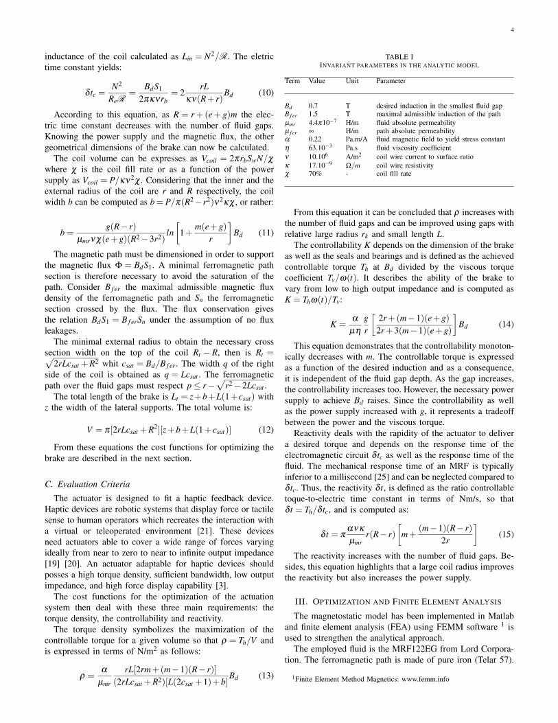
Fig. 4. Representation of the optimization algorithm. The geometricalconstrains are implemented in the analytic model. An initial solution isfound using the simulated annealing (SA) algorithm. The SA minimizes thefunction (Th − T )/T where T in order to guarantee a required torque T .The initial solution provided by the SA is sent to the sequential quadraticprogramming (SQP) algorithm which generates a finite element analysis tocalculate nonlinear behaviours. The materials characteristics are taken inaccount using a lookup table. The SQP minimizes the function 1/ρ in viewof maximizing the torque density. As output are determined m, L, rk , Nimax,q, T and rb.
Table I lists the parameters of the fluid, the ferromagneticpath and the coil adopted in the simulations. In the analyticalmodel the absolute permeability of the fluid µmr and thefield-to-yield stress constant α are assumed as constant. Thepermeability of the ferromagnetic path µ f er is considered asinfinite. The same parameters are used in the FEA except theB-H curves (magnetic flux density versus induced field) of thefluid and ferromagnetic material which are acquired from thedatasheets of each material. In the same way, by contrast tothe analytical model, in the FEA the fluid yield stress τy(H)is obtained as a non-linear function of the magnetic field.
The design specifications, the geometrical constraints andthe optimisation variables used in the optimization algorithmare listed bellow.
Design specifications: The minimal required controllablebraking torque is 3.2 Nm. In view of implementing the brakein a existing haptic device, a hollow shaft of 6 mm radiusmust be predicted and the external radius Rt must be inferiorto 30 mm. Due to manufacturing limitations and to avoid thedemormation of the cylinder, the thickness of each cylinderis set to e =1 mm. The emplacement of bearings and sealimposes r−q≥13 mm.
Geometrical constraints: In order to avoid saturation ofthe ferromagnetic path, the following geometric constraintsmust be respected. To avoid saturation on the top of the coil:Rt ≥
√2rLcsat +R2. On the adjacent section of the coil the
minimal width is q ≥ csatL. Finally, the ferromagnetic pathunder the gaps necessitates p≤ r−
√r2−2Lcsat .
Optimisation variables: The following parameters are themodel variables: the number of fluid gaps m, the inner radiusr of the smallest fluid gap, the fluid gap depth g, the length Lof each fluid gap, and the means radius of the coil rb.
Two critical parameters for optimising the brake are the fluidgap depth g and the number of fluid gaps m. The reactivityand the torque density are maximized when m tends to infinite.However, in order to maximize the controllability, m tends tozero. In the same way, the functions ρ , K, and δ t do not meet
−20 −10 0 10 20−20
−10
0
10
20
Fluid Gap Depth Variation [%]
Dev
iatio
n [%
]
−10 −5 0 5 10−20
−10
0
10
Length Variation [%]
Dev
iatio
n [%
]
ρK P
δ t
ρK P
δ t
Dev
iatio
n [%
]
Fig. 5. Influence of the fluid gap depth g and of the fluid gap length L onthe evaluation criteria. A compromise between ρ and K can be observed. Ifthe fluid gap is increased from 0.5 mm to 0.6 mm (+20%), K increases by14%. In the second figure, for L = 7 mm, ρ reaches its maximum value. Fora length variation superior to +7%, the ferromagnetic path on the right sideof the coil is saturated. For variation inferior to -11%, a 6 mm radius hollowshaft can not be built.
an optimal value as a function of g. Maximising the torquedensity necessitates the minimization of the fluid gap depth,while maximising the controllability implies a large fluid gap.Consequently, g determines the compromise controllabilityversus power supply and controllability versus torque density.Hence, g is choose to be set at 0.5 mm and optimisation willfocus on the maximization of the torque density.
The optimization algorithm represented in Fig. 4 comprisestwo successive steps. In the first step, a solution with respectto the geometric specifications and constraints is obtainedusing a ”simulated annealing algorithm” (SA). It consists ofa random search algorithm which statistically guarantees theconvergence of the model to the required torque T after afinite number of iterations. The SA minimizes the followingfunction:
f (Th) =|Th− T |
T(16)
The results provided by the SA are used in the ”sequentialquadratic programming” (SQP) algorithm which searches foran optimal solution that maximises the torque density. Thesolution provided by the SA algorithm guarantees that the SQPdoes not converge to a local minimum.
In order to maximize the torque density, the SQP minimizesthe function g(ρ):
g(ρ) =1ρ
(17)
The SQP communicates with the FEA software in order totake into account all magnetic saturation and non-linearities.The magnetic field is monitored for 10 levels of currentstrength varying from 0 A to 1 A. Results were obtainedfour fluid gaps. The smallest one has 22.5 mm radius, as aconsequence the other have 24 mm, 25.5 mm and 27 mmrespectively. The optimal fluid gap length is 7 mm.
6
coil
magnetic6path
magneticflux
hollow6shaft
12mm
bearing(3)6
6seals
30mmradius
non-magneticparts
39mm6width
(4)
(1)
(5)
(6)
(2) (7)
(8)
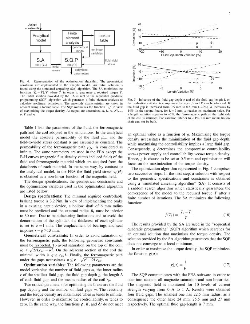
Fig. 6. CAD cross-view of the MRF-brake. Attached to the hollow rotaryshaft (1) a thin non-magnetic cylinder (5) supports two ferromagnetic cylinderswhich compose the fluid chamber. The coil is into the inner core (2) andthanks to the external housing (6), the magnetic flux is guided across thefluid gaps. A non-magnetic lateral support (4) blocks the translation of theaxis and bearings. The brake has 30 mm radius with a 6 mm radius hollowshaft and 39 mm length. The expected torque in the linear range is 3.4 Nm.
The fluid gap depth and the length of the gaps have animportant influence on the performance of the brake. Increas-ing the length improves the torque but also the necessarypower supply and the dimensions of the magnetic path. Anoptimal fluid gap length that maximizes the torque densitycan be found. With regard to the fluid gap depth however,the evaluation criteria do not present an maximal value aspresented in Fig. 5. A small change on these dimensionsaffects strongly the performance.
The design of the brake is shown in Fig. 6. The final externaldimensions are 39 mm width, 30 mm radius with 6 mm hollowshaft radius. The rotary hollow shaft (1) is connected to thestationary ferromagnetic path (2) using two bearings (3). Abearing cap (4) constraints their motion along the axis. Aroundthe shaft (1) is placed a thin rotary disc (5) which supportsthe rotary cylinders (7) of the fluid chamber. The rotary partsare (1) and (5). All but (2)(6)(7)(8) are non magnetic parts.By this means the magnetic flux is guided into the fluid gapswhile minimizing flux leakages.
The brake is designed to function with a maximum requiredmagnetic flux density Bd over the smallest fluid surface S1.Figure 7 shows the evolution of the mean induction value overS1 as a function of the current. According to the analyticalmodel, the desired induction is reached for a magnetomotiveforce of Nimax =232 A.turn. It is achieved with 475 turns of0.25 mm diameter wire and 0.49 A. According to the adoptedcurrent to surface ratio, this correponds to the maximal currentin norminal regime. Beyond this point, the fluid is expected to
0 0.2 0.4 0.6 0.8 10
0.2
0.4
0.6
0.8
1
1.2
1.4
Current[A]
B[T]
AnalyticFEA
0.49A
B[T]
Fig. 7. Magnetic flux density over the smallest fluid surface as a functionof the current. Using the analytical model, the surface reaches the desiredinduction of 0.7 T at 0.49 A and at 0.52 A using the finite element analysismodel. As speficied in the model, this is the maximal current in the norminalregime.
TABLE IIOPTIMIZED BRAKE DIMENSIONS
term value unit parameter
m 4 - number of fluid gapsr 22.5 mm smallest fluid gap radiusr2 24 mm second fluid gap radiusr3 25.5 mm third fluid gap radiusr4 27 mm fourth fluid gap radiusL 7 mm fluid gap lengthg 0.5 mm fluid gap depthrb 23.5 mm coil mean radiusRt 30 mm outer radius
saturate. Therefore, this is the limit of validity of the analyticalmodel. Using the FEA model, the desisted induction is attainedat Nimax=247 A.turn or rather 475 turns of wire and 0.52 A.This represents an error of +6% compared to the analyticalmodel (or 6% less torque for Nimax =232).
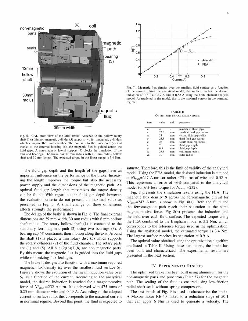
Fig. 8 presents the simulation results using the FEA. Themagnetic flux density B across the ferromagnetic circuit forNimax=247 A.turn is show in Fig. 8(a). Both the fluid andthe ferromagnetic path reach their saturation at the samemagnetomotive force. Fig 8(b) presents the induction andthe field over each fluid surface. The expected torque usingthe FEA combined to the Bingham model is 3.2 Nm, whichcorresponds to the reference torque used in the optimization.Using the analytical model, the estimated torque is 3.4 Nm.The largest surface reaches its saturation at 0.9 A.
The optimal value obtained using the optimization algorithmare listed in Table II. Using these parameters, the brake hasbeen built and characterized. The experimental results arepresented in the next section.
IV. EXPERIMENTAL RESULTS
The optimized brake has been built using aluminium for thenon-magnetic parts and pure iron (Telar 57) for the magneticpath. The sealing of the fluid is ensured using low-frictionradial shaft seals without spring compressors.
The test bench of Fig. 9 is used to characterise the brake.A Maxon motor RE-40 linked to a reduction stage of 50:1that can apply 6 Nm is used to generate a velocity. The
7
0.94 0.751.69 1.31 0.37
gap1
gap2
gap3
gap4
length
|B|[T](a) Finite element simulation
0 1 2 3 4 50.5
0.55
0.6
0.65
0.7
0.75
0.8
Length [mm]
|B| [
Tes
la]
0 1 2 3 4 50
50
100
150
200
250
300
|H| [
kA/m
]
|B||H|
gap 1gap 2
gap 3gap 4
(b) Magnetic field and magnetic flux density
Fig. 8. Simulation results using finite element analysis. In (a) the magneticflux density in the ferromagnetic path. The ferromagnetic path and the fluidreach their saturation at the same magnetic flux. The evolution of the inductionacross the fluid gaps is shown in (b). The fluid is exploited up to the desiredinduction of 0.7 T at 0.52 A.
torque transducer
DC motorMRF brake
Encoder
flexible coupling
flexible coupling
gears 50:1
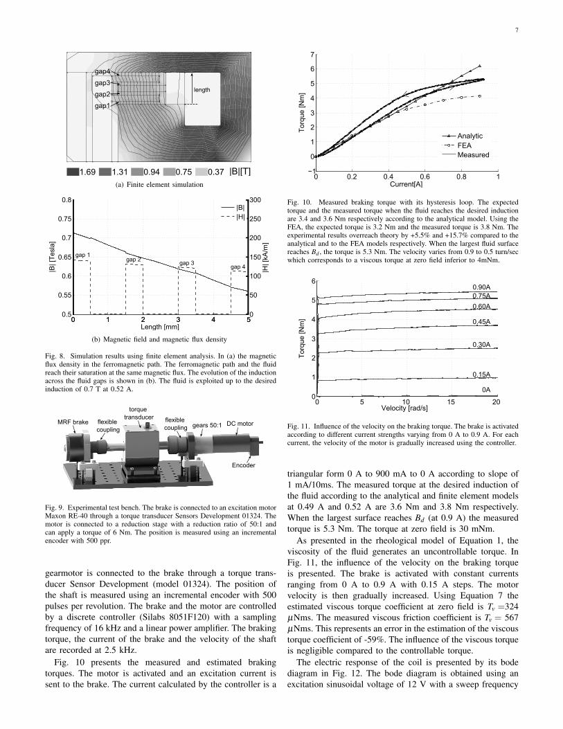
Fig. 9. Experimental test bench. The brake is connected to an excitation motorMaxon RE-40 through a torque transducer Sensors Development 01324. Themotor is connected to a reduction stage with a reduction ratio of 50:1 andcan apply a torque of 6 Nm. The position is measured using an incrementalencoder with 500 ppr.
gearmotor is connected to the brake through a torque trans-ducer Sensor Development (model 01324). The position ofthe shaft is measured using an incremental encoder with 500pulses per revolution. The brake and the motor are controlledby a discrete controller (Silabs 8051F120) with a samplingfrequency of 16 kHz and a linear power amplifier. The brakingtorque, the current of the brake and the velocity of the shaftare recorded at 2.5 kHz.
Fig. 10 presents the measured and estimated brakingtorques. The motor is activated and an excitation current issent to the brake. The current calculated by the controller is a
0 0.2 0.4 0.6 0.8 1−1
0
1
2
3
4
5
6
7
Current[A]
Tor
que
[Nm
]
AnalyticFEAMeasured
Tor
que
[Nm
]
Fig. 10. Measured braking torque with its hysteresis loop. The expectedtorque and the measured torque when the fluid reaches the desired inductionare 3.4 and 3.6 Nm respectively according to the analytical model. Using theFEA, the expected torque is 3.2 Nm and the measured torque is 3.8 Nm. Theexperimental results overreach theory by +5.5% and +15.7% compared to theanalytical and to the FEA models respectively. When the largest fluid surfacereaches Bd , the torque is 5.3 Nm. The velocity varies from 0.9 to 0.5 turn/secwhich corresponds to a viscous torque at zero field inferior to 4mNm.
0 5 10 15 200
1
2
3
4
5
6
Tor
que
[Nm
]
0A
0.15A
0.30A
0.45A
0.60A
0.75A0.90A
Tor
que2
[Nm
]
Velocity [rad/s]
Fig. 11. Influence of the velocity on the braking torque. The brake is activatedaccording to different current strengths varying from 0 A to 0.9 A. For eachcurrent, the velocity of the motor is gradually increased using the controller.
triangular form 0 A to 900 mA to 0 A according to slope of1 mA/10ms. The measured torque at the desired induction ofthe fluid according to the analytical and finite element modelsat 0.49 A and 0.52 A are 3.6 Nm and 3.8 Nm respectively.When the largest surface reaches Bd (at 0.9 A) the measuredtorque is 5.3 Nm. The torque at zero field is 30 mNm.
As presented in the rheological model of Equation 1, theviscosity of the fluid generates an uncontrollable torque. InFig. 11, the influence of the velocity on the braking torqueis presented. The brake is activated with constant currentsranging from 0 A to 0.9 A with 0.15 A steps. The motorvelocity is then gradually increased. Using Equation 7 theestimated viscous torque coefficient at zero field is Tv =324µNms. The measured viscous friction coefficient is Tv = 567µNms. This represents an error in the estimation of the viscoustorque coefficient of -59%. The influence of the viscous torqueis negligible compared to the controllable torque.
The electric response of the coil is presented by its bodediagram in Fig. 12. The bode diagram is obtained using anexcitation sinusoidal voltage of 12 V with a sweep frequency
8
10−2
100
102
104
106
−250
−200
−150
−100
−50
Frequency [Hz]
dB
(a) Voltage to current gain
10−2
100
102
104
106
−150
−100
−50
0
50
Frequency [Hz]
Pha
se [d
eg]
(b) Voltage to current phase
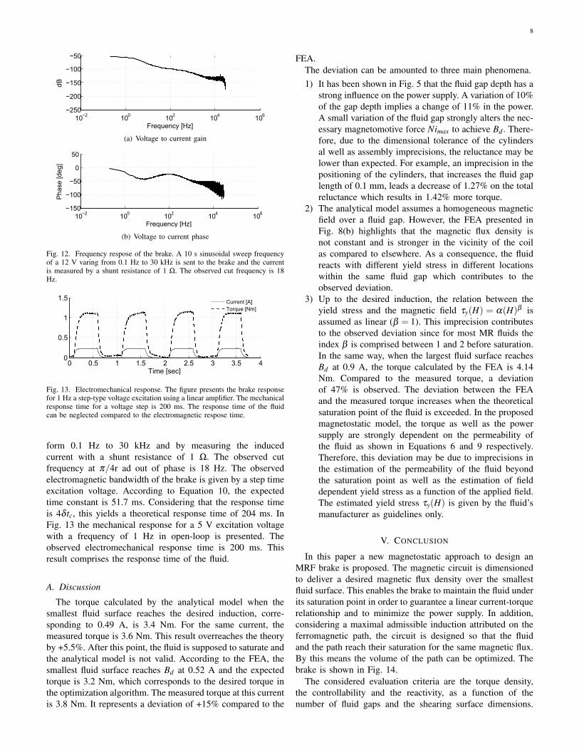
Fig. 12. Frequency respose of the brake. A 10 s sinusoidal sweep frequencyof a 12 V varing from 0.1 Hz to 30 kHz is sent to the brake and the currentis measured by a shunt resistance of 1 Ω. The observed cut frequency is 18Hz.
0 0.5 1 1.5 2 2.5 3 3.5 40
0.5
1
1.5
Time [sec]
Current [A]Torque [Nm]
0.5
Fig. 13. Electromechanical response. The figure presents the brake responsefor 1 Hz a step-type voltage excitation using a linear amplifier. The mechanicalresponse time for a voltage step is 200 ms. The response time of the fluidcan be neglected compared to the electromagnetic respose time.
form 0.1 Hz to 30 kHz and by measuring the inducedcurrent with a shunt resistance of 1 Ω. The observed cutfrequency at π/4r ad out of phase is 18 Hz. The observedelectromagnetic bandwidth of the brake is given by a step timeexcitation voltage. According to Equation 10, the expectedtime constant is 51.7 ms. Considering that the response timeis 4δ tc, this yields a theoretical response time of 204 ms. InFig. 13 the mechanical response for a 5 V excitation voltagewith a frequency of 1 Hz in open-loop is presented. Theobserved electromechanical response time is 200 ms. Thisresult comprises the response time of the fluid.
A. Discussion
The torque calculated by the analytical model when thesmallest fluid surface reaches the desired induction, corre-sponding to 0.49 A, is 3.4 Nm. For the same current, themeasured torque is 3.6 Nm. This result overreaches the theoryby +5.5%. After this point, the fluid is supposed to saturate andthe analytical model is not valid. According to the FEA, thesmallest fluid surface reaches Bd at 0.52 A and the expectedtorque is 3.2 Nm, which corresponds to the desired torque inthe optimization algorithm. The measured torque at this currentis 3.8 Nm. It represents a deviation of +15% compared to the
FEA.The deviation can be amounted to three main phenomena.1) It has been shown in Fig. 5 that the fluid gap depth has a
strong influence on the power supply. A variation of 10%of the gap depth implies a change of 11% in the power.A small variation of the fluid gap strongly alters the nec-essary magnetomotive force Nimax to achieve Bd . There-fore, due to the dimensional tolerance of the cylindersal well as assembly imprecisions, the reluctance may belower than expected. For example, an imprecision in thepositioning of the cylinders, that increases the fluid gaplength of 0.1 mm, leads a decrease of 1.27% on the totalreluctance which results in 1.42% more torque.
2) The analytical model assumes a homogeneous magneticfield over a fluid gap. However, the FEA presented inFig. 8(b) highlights that the magnetic flux density isnot constant and is stronger in the vicinity of the coilas compared to elsewhere. As a consequence, the fluidreacts with different yield stress in different locationswithin the same fluid gap which contributes to theobserved deviation.
3) Up to the desired induction, the relation between theyield stress and the magnetic field τy(H) = α(H)β isassumed as linear (β = 1). This imprecision contributesto the observed deviation since for most MR fluids theindex β is comprised between 1 and 2 before saturation.In the same way, when the largest fluid surface reachesBd at 0.9 A, the torque calculated by the FEA is 4.14Nm. Compared to the measured torque, a deviationof 47% is observed. The deviation between the FEAand the measured torque increases when the theoreticalsaturation point of the fluid is exceeded. In the proposedmagnetostatic model, the torque as well as the powersupply are strongly dependent on the permeability ofthe fluid as shown in Equations 6 and 9 respectively.Therefore, this deviation may be due to imprecisions inthe estimation of the permeability of the fluid beyondthe saturation point as well as the estimation of fielddependent yield stress as a function of the applied field.The estimated yield stress τy(H) is given by the fluid’smanufacturer as guidelines only.
V. CONCLUSION
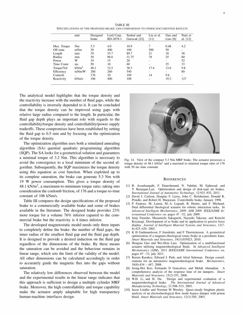
In this paper a new magnetostatic approach to design anMRF brake is proposed. The magnetic circuit is dimensionedto deliver a desired magnetic flux density over the smallestfluid surface. This enables the brake to maintain the fluid underits saturation point in order to guarantee a linear current-torquerelationship and to minimize the power supply. In addition,considering a maximal admissible induction attributed on theferromagnetic path, the circuit is designed so that the fluidand the path reach their saturation for the same magnetic flux.By this means the volume of the path can be optimized. Thebrake is shown in Fig. 14.
The considered evaluation criteria are the torque density,the controllability and the reactivity, as a function of thenumber of fluid gaps and the shearing surface dimensions.
9
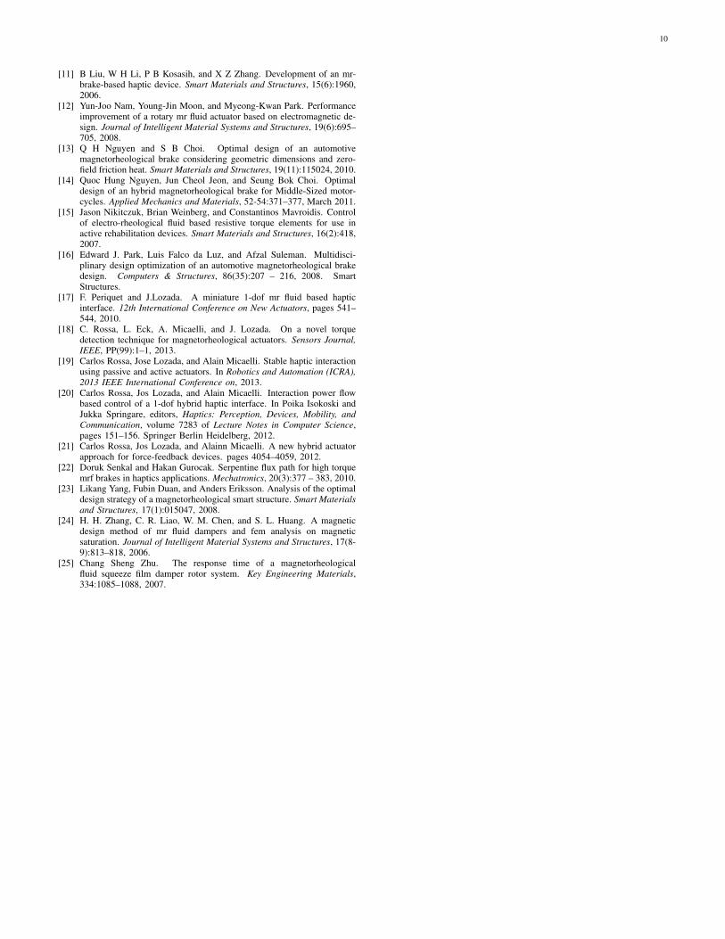
TABLE IIISPECIFICATIONS OF THE PROPOSED BRAKE AND COMPARISON TO OTHER DOCUMENTED RESULTS
unit Designed Lord Corp. Senkal and Liu et al. Guo and Nam etbrake RD-2078-1 Gurocak [22] [11] Liao [6] al. [12]
Max. Torque Nm 5.3 4.0 10.9 7 0.48 4.2Off-state mNm 30 400 100 500 50 -Length mm 39 35.7 89.7 21 18 38Radius mm 30 96.6 31.75 78 25 60Power W 19 15 20 - - 52Time Const ms 50 10 60 - 25 33Torque/Vol kN/m2 48.1 12.5 38.3 17.4 13.6 9.8Efficiency mNm/W 280 260 540 - - 80Controll. - 176 10 109 14 9.6 -Reactivity kNm/s 106 400 108 - 19.2 127
The analytical model highlights that the torque density andthe reactivity increase with the number of fluid gaps, while thecontrollability is inversely depended to it. It can be concludedthat the torque density can be improved using gaps withrelative large radius compared to the length. In particular, thefluid gap depth plays an important role with regards to thecontrollability/torque density and controllability/power supplytradeoffs. These compromises have been established by settingthe fluid gap to 0.5 mm and by focusing on the optimizationof the torque density.
The optimization algorithm uses both a simulated annealingalgorithm (SA) quential quadratic programming algorithm(SQP). The SA looks for a geometrical solution and guaranteesa minimal torque of 3.2 Nm. This algorithm is necessary toavoid the convergence to a local minimum of the second al-gorithm. Subsequently, the SQP maximizes the torque densityusing this equation as cost function. When exploited up toits complete saturation, the brake can generate 5.3 Nm with19 W power consumption. This gives a torque density of48.1 kN/m2, a maximum-to-minimum torque ratio, taking intoconsideration the coulomb friction, of 176 and a torque-to-timeconstant of 106 kNm/s.
Table III compares the design specifications of the proposedbrake to a commercially available brake and some of brakesavailable in the literature. The designed brake provides 23%more torque for a volume 76% inferior capared to the com-mercial brake but the reactivity is 4 times inferior.
The developed magnetostatic model needs only three inputsto completely define the brake: the number of fluid gaps, theinner radius of the smallest fluid gap and the fluid gap depth.It is designed to provide a desired induction on the fluid gapregardless of the dimensions of the brake. By these meansthe saturation can be avoided and the behaviour remains inlinear range, which sets the limit of the validity of the model.All other dimensions can be calculated accordingly in orderto accurately guide the magnetic flux into the gaps withoutsaturation.
The relatively low differences observed between the modeland the experimental results in the linear range indicates thatthis approach is sufficient to design a multiple cylinder MRFbrake. Moreover, the high controllability and torque capabilitymake the actuator amply adaptable for high transparencyhuman-machine interfaces design.
Fig. 14. View of the compact 5.3 Nm MRF brake. The actuator possesses atorque density of 48.1 kN/m2 and a maximal to minimal torque ratio of 176with 50 ms time constant.
REFERENCES
[1] B. Assadsangabi, F. Daneshmand, N. Vahdati, M. Eghtesad, andY. Bazargan-Lari. Optimization and design of disk-type mr brakes.International Journal of Automotive Technology, 12:921–932, 2011.
[2] David J. Carlson, Douglas F. Leroy, John C. Holzheimer, Donald R.Prindle, and Robert H. Marjoram. Controllable brake, January 1998.
[3] P. Fauteux, M. Lauria, M.-A. Legault, B. Heintz, and F. Michaud.Dual differential rheological actuator for robotic interaction tasks. InAdvanced Intelligent Mechatronics, 2009. AIM 2009. IEEE/ASME In-ternational Conference on, pages 47 –52, july 2009.
[4] Junji Furusho, Masamichi Sakaguchi, Naoyuki Takesue, and KenichiKoyanagi. Development of er brake and its application to passive forcedisplay. Journal of Intelligent Material Systems and Structures, 13(7-8):425–429, 2002.
[5] K H Gudmundsson, F Jonsdottir, and F Thorsteinsson. A geometricaloptimization of a magneto-rheological rotary brake in a prosthetic knee.Smart Materials and Structures, 19(3):035023, 2010.
[6] Hongtao Guo and Wei-Hsin Liao. Optimization of a multifunctionalactuator utilizing magnetorheological fluids. In Advanced IntelligentMechatronics (AIM), 2011 IEEE/ASME International Conference on,pages 67 –72, july 2011.
[7] Kerem Karakoc, Edward J. Park, and Afzal Suleman. Design consid-erations for an automotive magnetorheological brake. Mechatronics,18(8):434 – 447, 2008.
[8] Jeong-Hoi Koo, Fernando D Goncalves, and Mehdi Ahmadian. Acomprehensive analysis of the response time of mr dampers. SmartMaterials and Structures, 15(2):351, 2006.
[9] W.H. Li and H. Du. Design and experimental evaluation of amagnetorheological brake. The International Journal of AdvancedManufacturing Technology, 21:508–515, 2003.
[10] Jason Lindler and Norman M Wereley. Quasi-steady bingham plasticanalysis of an electrorheological flow mode bypass damper with pistonbleed. Smart Materials and Structures, 12(3):305, 2003.
10
[11] B Liu, W H Li, P B Kosasih, and X Z Zhang. Development of an mr-brake-based haptic device. Smart Materials and Structures, 15(6):1960,2006.
[12] Yun-Joo Nam, Young-Jin Moon, and Myeong-Kwan Park. Performanceimprovement of a rotary mr fluid actuator based on electromagnetic de-sign. Journal of Intelligent Material Systems and Structures, 19(6):695–705, 2008.
[13] Q H Nguyen and S B Choi. Optimal design of an automotivemagnetorheological brake considering geometric dimensions and zero-field friction heat. Smart Materials and Structures, 19(11):115024, 2010.
[14] Quoc Hung Nguyen, Jun Cheol Jeon, and Seung Bok Choi. Optimaldesign of an hybrid magnetorheological brake for Middle-Sized motor-cycles. Applied Mechanics and Materials, 52-54:371–377, March 2011.
[15] Jason Nikitczuk, Brian Weinberg, and Constantinos Mavroidis. Controlof electro-rheological fluid based resistive torque elements for use inactive rehabilitation devices. Smart Materials and Structures, 16(2):418,2007.
[16] Edward J. Park, Luis Falco da Luz, and Afzal Suleman. Multidisci-plinary design optimization of an automotive magnetorheological brakedesign. Computers & Structures, 86(35):207 – 216, 2008. SmartStructures.
[17] F. Periquet and J.Lozada. A miniature 1-dof mr fluid based hapticinterface. 12th International Conference on New Actuators, pages 541–544, 2010.
[18] C. Rossa, L. Eck, A. Micaelli, and J. Lozada. On a novel torquedetection technique for magnetorheological actuators. Sensors Journal,IEEE, PP(99):1–1, 2013.
[19] Carlos Rossa, Jose Lozada, and Alain Micaelli. Stable haptic interactionusing passive and active actuators. In Robotics and Automation (ICRA),2013 IEEE International Conference on, 2013.
[20] Carlos Rossa, Jos Lozada, and Alain Micaelli. Interaction power flowbased control of a 1-dof hybrid haptic interface. In Poika Isokoski andJukka Springare, editors, Haptics: Perception, Devices, Mobility, andCommunication, volume 7283 of Lecture Notes in Computer Science,pages 151–156. Springer Berlin Heidelberg, 2012.
[21] Carlos Rossa, Jos Lozada, and Alainn Micaelli. A new hybrid actuatorapproach for force-feedback devices. pages 4054–4059, 2012.
[22] Doruk Senkal and Hakan Gurocak. Serpentine flux path for high torquemrf brakes in haptics applications. Mechatronics, 20(3):377 – 383, 2010.
[23] Likang Yang, Fubin Duan, and Anders Eriksson. Analysis of the optimaldesign strategy of a magnetorheological smart structure. Smart Materialsand Structures, 17(1):015047, 2008.
[24] H. H. Zhang, C. R. Liao, W. M. Chen, and S. L. Huang. A magneticdesign method of mr fluid dampers and fem analysis on magneticsaturation. Journal of Intelligent Material Systems and Structures, 17(8-9):813–818, 2006.
[25] Chang Sheng Zhu. The response time of a magnetorheologicalfluid squeeze film damper rotor system. Key Engineering Materials,334:1085–1088, 2007.
Related Documents