830 IEEE TRANSACTIONS ON NEURAL SYSTEMS AND REHABILITATION ENGINEERING, VOL. 21, NO. 5, SEPTEMBER 2013 Development of a Multichannel Vestibular Prosthesis Prototype by Modification of a Commercially Available Cochlear Implant Nicolas S. Valentin, Kristin N. Hageman, Chenkai Dai, Charles C. Della Santina, and Gene Y. Fridman, Member, IEEE Abstract—No adequate treatment exists for individuals who re- main disabled by bilateral loss of vestibular (inner ear inertial) sensation despite rehabilitation. We have restored vestibular re- flexes using lab-built multichannel vestibular prostheses (MVPs) in animals, but translation to clinical practice may be best accom- plished by modification of a commercially available cochlear im- plant (CI). In this interim report, we describe preliminary efforts toward that goal. We developed software and circuitry to sense head rotation and drive a CI’s implanted stimulator (IS) to deliver up to 1 K pulses/s via nine electrodes implanted near vestibular nerve branches. Studies in two rhesus monkeys using the modi- fied CI revealed in vivo performance similar to our existing ded- icated MVPs. A key focus of our study was the head-worn unit (HWU), which magnetically couples across the scalp to the IS. The HWU must remain securely fixed to the skull to faithfully sense head motion and maintain continuous stimulation. We measured normal and shear force thresholds at which HWU-IS decoupling occurred as a function of scalp thickness and calculated pressure exerted on the scalp. The HWU remained attached for human scalp thicknesses from 3–7.8 mm for forces experienced during routine daily activities, while pressure on the scalp remained below capil- lary perfusion pressure. Index Terms—Cochlear, dizziness, electrical stimulation, im- plant, prosthesis, vestibular. I. INTRODUCTION T HE VESTIBULAR labyrinth helps maintain gaze and postural stability by driving reflexive eye and body movements in response to head motion. Rotational head motion is normally encoded into vestibular nerve activity by six semi- circular canals (SCCs), three in each inner ear, which modulate afferent neuron firing rates. Damage to sensory hair cells in the SCCs can occur due to infection, Ménière’s disease or ototoxic medications, causing impairment of vestibular reflexes. The re- sulting disequilibrium, blurred vision during head movements, Manuscript received September 20, 2012; revised January 21, 2013 and March 13, 2013; accepted April 08, 2013. Date of publication May 01, 2013; date of current version September 04, 2013. This work was supported by the National Institute on Deafness and Other Communication Disorders (NIDCD)under Grant R01DC009255 and Grant 1F31DC010099-01A1. The authors are with the Johns Hopkins Vestibular NeuroEngineering Lab, Department of Otolaryngology-Head & Neck Surgery and Biomedical Engineering, Johns Hopkins School of Medicine, Baltimore, MD 21205 USA (e-mail: [email protected]). Color versions of one or more of the figures in this paper are available online at http://ieeexplore.ieee.org. Digital Object Identifier 10.1109/TNSRE.2013.2259261 and postural instability degrade quality of life and increase risk of injury due to falls [4]. There is currently no adequate treatment for individuals with bilateral vestibular hypofunction (BVH) who fail to improve despite vestibular rehabilitation exercises. Preclinical studies in rodents and nonhuman primates strongly suggest that a multi- channel vestibular prosthesis (MVP) could improve quality of life for such patients [5]–[12]. Significant effort has been directed toward reducing the physical size of the sensors and the signal processing hard- ware of the vestibular prosthesis with the intent to develop a fully implantable device [10], [11], [18], [39]–[41]. However, considering the large capital investment and regulatory burden required to create a new implantable stimulator de novo, translation to clinical practice may be best accomplished by modification of a commercially available cochlear implant (CI) system. Initial attempts at prosthetic vestibular stimulation in humans using cochlear implant (CI) stimulators have revealed promising preliminary results [13]–[16], [37], [38]. While these stimulation experiments successfully confirmed the ability of a CI to evoke the intended response of the vestibular nerve via patterned stimulation delivered to custom electrodes, they did not address the overall design that would enable a CI to be used as a vestibular implant. For a CI to function as a vestibular prosthesis, the system would need the ability to not only stimulate the nerve, but also to sense head rotation velocity in 3-D, process the data and modulate the stimulation pattern delivered to each of the three branches of the nerve in real time, and be self-contained and compact so that it could be worn by a patient. A more complete system design that would adapt a commercial CI to function as a vestibular prosthesis could expedite translating research findings into clinical use by overcoming significant technological and regulatory hurdles. We adapted a commercially available CI system to function as a semi-implantable MVP. Our design includes motion sen- sors and a power source coupled magnetically to a modified CI’s implanted stimulator (IS) analogous to a method suggested in a patent publication by Garnham et al. [36]. Using a CI to implement a complete vestibular prosthesis presents a unique challenge. Unlike a CI, an MVP uses gyroscopes to accurately sense skull rotation in 3-D. Consequently, transcutaneous mag- netic (mechanical) coupling between the external head-worn component that contains the gyroscopes and the magnetically coupled implant must withstand head movements encountered during normal daily activities (e.g., walking, jogging, climbing 1534-4320 © 2013 IEEE

Welcome message from author
This document is posted to help you gain knowledge. Please leave a comment to let me know what you think about it! Share it to your friends and learn new things together.
Transcript

830 IEEE TRANSACTIONS ON NEURAL SYSTEMS AND REHABILITATION ENGINEERING, VOL. 21, NO. 5, SEPTEMBER 2013
Development of a Multichannel Vestibular ProsthesisPrototype by Modification of a Commercially
Available Cochlear ImplantNicolas S. Valentin, Kristin N. Hageman, Chenkai Dai, Charles C. Della Santina, and
Gene Y. Fridman, Member, IEEE
Abstract—No adequate treatment exists for individuals who re-main disabled by bilateral loss of vestibular (inner ear inertial)sensation despite rehabilitation. We have restored vestibular re-flexes using lab-built multichannel vestibular prostheses (MVPs)in animals, but translation to clinical practice may be best accom-plished by modification of a commercially available cochlear im-plant (CI). In this interim report, we describe preliminary effortstoward that goal. We developed software and circuitry to sensehead rotation and drive a CI’s implanted stimulator (IS) to deliverup to 1 K pulses/s via nine electrodes implanted near vestibularnerve branches. Studies in two rhesus monkeys using the modi-fied CI revealed in vivo performance similar to our existing ded-icated MVPs. A key focus of our study was the head-worn unit(HWU), which magnetically couples across the scalp to the IS. TheHWU must remain securely fixed to the skull to faithfully sensehead motion and maintain continuous stimulation. We measurednormal and shear force thresholds at which HWU-IS decouplingoccurred as a function of scalp thickness and calculated pressureexerted on the scalp. TheHWUremained attached for human scalpthicknesses from 3–7.8 mm for forces experienced during routinedaily activities, while pressure on the scalp remained below capil-lary perfusion pressure.
Index Terms—Cochlear, dizziness, electrical stimulation, im-plant, prosthesis, vestibular.
I. INTRODUCTION
T HE VESTIBULAR labyrinth helps maintain gaze andpostural stability by driving reflexive eye and body
movements in response to head motion. Rotational head motionis normally encoded into vestibular nerve activity by six semi-circular canals (SCCs), three in each inner ear, which modulateafferent neuron firing rates. Damage to sensory hair cells in theSCCs can occur due to infection, Ménière’s disease or ototoxicmedications, causing impairment of vestibular reflexes. The re-sulting disequilibrium, blurred vision during head movements,
Manuscript received September 20, 2012; revised January 21, 2013 andMarch 13, 2013; accepted April 08, 2013. Date of publication May 01,2013; date of current version September 04, 2013. This work was supportedby the National Institute on Deafness and Other Communication Disorders(NIDCD)under Grant R01DC009255 and Grant 1F31DC010099-01A1.The authors are with the Johns Hopkins Vestibular NeuroEngineering
Lab, Department of Otolaryngology-Head & Neck Surgery and BiomedicalEngineering, Johns Hopkins School of Medicine, Baltimore, MD 21205 USA(e-mail: [email protected]).Color versions of one or more of the figures in this paper are available online
at http://ieeexplore.ieee.org.Digital Object Identifier 10.1109/TNSRE.2013.2259261
and postural instability degrade quality of life and increase riskof injury due to falls [4].There is currently no adequate treatment for individuals with
bilateral vestibular hypofunction (BVH) who fail to improvedespite vestibular rehabilitation exercises. Preclinical studies inrodents and nonhuman primates strongly suggest that a multi-channel vestibular prosthesis (MVP) could improve quality oflife for such patients [5]–[12].Significant effort has been directed toward reducing the
physical size of the sensors and the signal processing hard-ware of the vestibular prosthesis with the intent to develop afully implantable device [10], [11], [18], [39]–[41]. However,considering the large capital investment and regulatory burdenrequired to create a new implantable stimulator de novo,translation to clinical practice may be best accomplished bymodification of a commercially available cochlear implant (CI)system. Initial attempts at prosthetic vestibular stimulation inhumans using cochlear implant (CI) stimulators have revealedpromising preliminary results [13]–[16], [37], [38]. While thesestimulation experiments successfully confirmed the ability ofa CI to evoke the intended response of the vestibular nervevia patterned stimulation delivered to custom electrodes, theydid not address the overall design that would enable a CIto be used as a vestibular implant. For a CI to function asa vestibular prosthesis, the system would need the ability tonot only stimulate the nerve, but also to sense head rotationvelocity in 3-D, process the data and modulate the stimulationpattern delivered to each of the three branches of the nerve inreal time, and be self-contained and compact so that it could beworn by a patient. A more complete system design that wouldadapt a commercial CI to function as a vestibular prosthesiscould expedite translating research findings into clinical use byovercoming significant technological and regulatory hurdles.We adapted a commercially available CI system to function
as a semi-implantable MVP. Our design includes motion sen-sors and a power source coupled magnetically to a modifiedCI’s implanted stimulator (IS) analogous to a method suggestedin a patent publication by Garnham et al. [36]. Using a CI toimplement a complete vestibular prosthesis presents a uniquechallenge. Unlike a CI, an MVP uses gyroscopes to accuratelysense skull rotation in 3-D. Consequently, transcutaneous mag-netic (mechanical) coupling between the external head-worncomponent that contains the gyroscopes and the magneticallycoupled implant must withstand head movements encounteredduring normal daily activities (e.g., walking, jogging, climbing
1534-4320 © 2013 IEEE

VALENTIN et al.: DEVELOPMENT OF A MULTICHANNEL VESTIBULAR PROSTHESIS PROTOTYPE 831
Fig. 1. Modified cochlear implant circuit block diagram. Our MCI prototypeconsists of 1) the BWU, 2) the HWU, and 3) the IS. The BWU samples sensorson the HWU every 5 ms and calculates instantaneous rate of stimulation. Pulsecommands are sent to the HWU and relayed via radio frequency to the IS, whichdelivers frequency-modulated biphasic charge-balanced pulses to the vestibularnerve. Power is provided by a 3.3 V supply, drawn from a 3.6 V Li-ion batterypack housed in the BWU.
stairs), which can include head rotations with peak velocities upto and accelerations up to (although thevast majority of head movements are much slower) [17]. At thesame time, forces on the intervening scalp must not exceed thesafety criteria indicated by the capillary perfusion pressure.We describe our design of the modified CI (MCI), system
bench tests and animal experiments, and we examine the tech-nical challenge of maintaining a safe but strong transcutaneousmagnetic coupling between the head-worn unit (HWU) andthe IS. Our findings highlight factors that must be consideredin development of an MCI intended to maintain uninterruptedvestibular nerve stimulation.
II. DEVICE DESCRIPTION
A. System Overview
As shown in Fig. 1, the MCI prototype comprises three maincomponents: a belt-worn unit (BWU), an external HWU andan IS. The BWU provides power to the HWU and reads headmotion information from gyroscopes and linear accelerometersin the HWU via I2C. Based on the gyroscope measurements, theBWU determines the instantaneous stimulation pulse-rate foreach electrode, schedules and sends a command to the HWU todeliver each pulse. The HWU relays the pulse information viathe radio-frequency (RF) link to the IS. IS in turn delivers eachspecified electrical current pulse to the vestibular nerve via oneof the nine electrodes implanted in the labyrinth. Under normaloperating conditions, the MCI draws 21.1 mA from a regulated3.3 V supply. The IS consumes 11.4 mA and the BWU+HWUconsumes 9.7 mA.
B. Belt-Worn Unit
The BWU holds two 3.6 V lithium-ion AAA-size batteriesin parallel (in case one loses charge or is removed), whichcontinuously power the whole MCI for up to 11 h via a 3.3 Vlinear regulator. BWU circuitry comprises surface-mount com-ponents on one side of a two-layer mm printedcircuit board (PCB). A mixed-signal microcontroller ( ;MSP430F1611, Texas Instruments, Dallas, TX, USA), running
at 8 MHz, controls the system. Using a second timer running at32.768 KHz, the samples gyroscope in the HWU every 5 ms
and controls stimulus pulse timing withprecision. A Bluetooth module (RN-42, Roving Networks, LosGatos, CA, USA) facilitates parameter changes for patient fit-ting. This small mm low power device provideswireless communication at up to 3 Mb/s, enabling subjects tomove within 20 m of a fitting computer while parameters areadjusted. All components are encased in a plastic housing forprotection and easy attachment to the patient’s belt. Includingbatteries, the whole BWU weighs 49 g.
C. Head-Worn Unit
HWU circuitry occupies both sides of a four-layermm PCB including a “slave” (MSP430F1611) that re-
ceives commands from the BWU via I2C and relays them tothe IS via the CI’s RF link, a surface-mount tri-axial ITG-3200gyroscope (InvenSense, Sunnyvale, CA, USA) for angular ve-locity measurement, and a ADXL345 tri-axial linear accelerom-eter (Analog Devices, Norwood, MA, USA). The gyroscopethat we are using for the MCI is more sensitive than the onesthat we used previously with the MVP, at 14 using a16-bit ADC embedded in the device. As with our previousMVPdesign, an accelerometer is included in the HWU to accuratelymeasure the HWU’s orientation relative to the skull during thefitting sessions [18]. These measurements would in turn allowthe real time software to compensate for misalignment betweenSCC’s and the HWU’s gyroscope axes.HWU components are encased in a plastic housing coupled
magnetically across the scalp to the IS via three replaceablemagnets arranged to align with magnets on the IS, positioningthe HWU so that gyroscope axes approximately align with theSCC axes. The HWUweighs 10 g without magnets and 18 gwith the heaviest magnets.
D. Internal Stimulator
The MCI uses a modified “Concerto” IS (Med-El Elek-tromedizinische Gerate GmbH, Innsbruck, Austria). Its
mm hermetic housing, inductive coil, 12feedthroughs and internal circuitry remain unchanged. How-ever, two alterations were made.The first modification replaces the standard CI electrode array
with a new array designed for stimulation of the vestibularnerve. The electrode array design was developed for nonhumanprimate studies for use with the MVP [18]. In brief, an array ofnine active and two reference 90/10 Pt/Ir electrode contacts isembedded within two silicone carriers. The design is based onanatomic measurements from 3-D reconstructions of macaquetemporal bones. A dual fork-shaped array facilitates placementinto the horizontal and superior SCC ampullae, while a secondarray facilitates placement into the posterior SCC ampulla. Thereference electrode can be positioned either in the temporalismuscle or in the perilymphatic space of the common cruswithin the labyrinth.The second modification is the addition of magnets for en-
hanced internal-external device coupling. The need for accu-rate head velocity measurements and continuous stimulation re-
832 IEEE TRANSACTIONS ON NEURAL SYSTEMS AND REHABILITATION ENGINEERING, VOL. 21, NO. 5, SEPTEMBER 2013
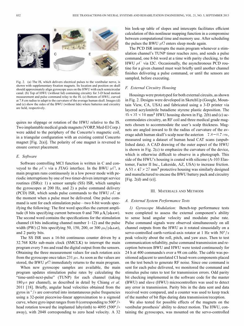
Fig. 2. (a) The IS, which delivers electrical pulses to the vestibular nerve, isshown with supplementary fixation magnets. Its location and position on skullshould approximately align gyroscope axes on the HWUwith each semicircularcanal. (b) Top of HWU (without lid) containing circuitry for 3-D head motionmeasurement and pulse command relay to the IS. (c) Bottom of HWU, curvedat 7.8 cm radius to adapt to the curvature of the average human skull. Images (d)and (e) show the sides of the BWU (without lids) where batteries and circuitryare held, respectively.
quires no slippage or rotation of the HWU relative to the IS.Two implantable medical grademagnets (VORP,Med-El Corp.)were added to the periphery of the Concerto’s magnetic coil,in a triangular configuration with an existing central Concertomagnet [Fig. 2(a)]. The polarity of one magnet is reversed toensure correct placement.
E. Software
Software controlling MCI function is written in C and con-veyed to the via a JTAG interface. In the BWU , amain program runs continuously in a low power mode with pe-riodic interruptions by one of two timer-driven interrupt serviceroutines (ISRs): 1) a sensor sample (SS) ISR, which samplesthe gyroscopes at 200 Hz, and 2) a pulse command delivery(PCD) ISR, which sends pulse commands to the HWU atthe moment when a pulse must be delivered. One pulse com-mand is sent for each stimulation pulse—two 8-bit words spec-ifying the following: The first word specifies the current ampli-tude (8 bits specifying current between 0 and 700 ).The second word contains the specifications for the stimulationchannel (4 bits indicating channel number 1–12) and the pulsewidth (PW) (2 bits specifying 50, 150, 200, or 300 ),and 2 parity bits.The SS ISR uses a 16-bit continuous counter driven by a
32.768 KHz sub-main clock (SMCLK) to interrupt the mainprogram every 5 ms and read the digital output from the sensors.Obtaining the three measurement values for each rotation axisfrom the gyroscope once takes 231 . As soon as the values arestored, the BWU immediately returns to the main program.When new gyroscope samples are available, the main
program updates stimulation pulse rates by calculating the“time-until-next-pulse” (TUNP) for each channel (taking180 per channel), as described in detail by Chiang et al.2011 [18]. Briefly, angular head velocities obtained from thegyros in are converted into instantaneous pulse frequenciesusing a 32-point piecewise-linear approximation to a sigmoidcurve, where gyro input ranges from 0 (corresponding to 500head rotation toward the implanted labyrinth) to 4095 (500away), with 2048 corresponding to zero head velocity. A 32
bin look-up table of slopes and intercepts facilitates efficientcalculation of this nonlinear mapping function in a compromisebetween computational time and memory use. After schedulingthe pulses the BWU enters sleep mode again.The PCD ISR interrupts the main program whenever a stim-
ulation channel’s TUNP timer reaches zero, and sends a pulsecommand, one 8-bit word at a time with parity checking, to theHWU via I2C. Occasionally, the asynchronous PCD rou-tine for a given channel must wait briefly until another channelfinishes delivering a pulse command, or until the sensors aresampled, before executing.
F. External Circuitry Housing
Housingswere prototyped for both external circuits, as shownin Fig. 2. Designs were developed in SketchUp (Google, Moun-tain View, CA, USA) and fabricated using a 3-D printer vialayered acrylonitrile butadiene styrene plastic deposition. The
mm HWU housing shown in Fig. 2(b) and (c) ac-commodates circuitry, an RF coil and three medical grade mag-nets chosen to accommodate the user’s scalp thickness. Mag-nets are angled inward to fit the radius of curvature of the av-erage adult human skull’s scalp near the asterion ,measured using a dataset of human head CAT scans (unpub-lished data). A CAD drawing of the outer aspect of the HWUis shown in Fig. 2(c) to emphasize the curvature of the device,which is otherwise difficult to observe in a photograph. Thisside of the HWU’s housing is coated with silicone (A-103 Elas-tomer, Factor II Inc., Lakeside, AZ, USA) to increase friction.A mm protective housing was similarly designedand manufactured to encase the BWU battery pack and circuitry[Fig. 2(d) and (e)].
III. MATERIALS AND METHODS
A. External System Performance Tests
1) Gyroscope Modulation: Bench-top performance testswere completed to assess the external component’s abilityto sense head angular velocity and modulate pulse rate.Pulse command signals were observed simultaneously on allchannel outputs from the HWU as it rotated sinusoidally on aservo-controlled earth-vertical-axis rotator at 1 Hz with 50peak velocity about the roll, pitch, and yaw axes. Then to testcommunication reliability, pulse command transmission and re-ception between BWU and HWU were tested continuously for24 h at 400 commands/s over a 98 cm cable. The cable was po-sitioned adjacent to unrelated CI head-worn components placedon the test bench to generate RF noise. Since one command issent for each pulse delivered, we monitored the command andstimulus pulse rates to test for transmission errors. Odd paritybit checking implemented in the software code for the master(BWU) and slave (HWU) microcontrollers was used to detectany error in transmission. Parity bits in the data sent and datareceived were compared, and a counter was used to keep trackof the number of bit flips during data transmission/reception.We also tested for possible effects of the magnets on the
vestibular prosthesis’ ability to detect motion. The HWU, con-taining the gyroscopes, was mounted on the servo-controlled

VALENTIN et al.: DEVELOPMENT OF A MULTICHANNEL VESTIBULAR PROSTHESIS PROTOTYPE 833
earth-vertical-axis rotator. Frequency modulated pulse com-mand signals were monitored on an output channel as the HWUwas rotated sinusoidally at 1 Hz with 50 dps peak velocityabout the pitch axis. The pulse rates were compared for 10 cy-cles of each of the following cases: HWU in the presence of nomagnets, one, and three (in a triangular configuration) Amadefive magnets (the strongest magnets used in our force/pressuremeasurements).2) Magnetic Retention Forces and Pressure: Proper MCI
function requires the HWU to remain securely coupled to theIS across the scalp to both transduce head motion accuratelyand maintain power and signal transmission. (Abrupt HWU-ISdecoupling would halt stimulation, causing vertigo and nys-tagmus due to a sudden drop in vestibular nerve activity. Rela-tive motion between the HWU and IS would cause less severebut nonetheless unpleasant symptoms due to inaccurate percep-tion of head motion and misalignment between head motionand reflexive responses of extraocular and postural muscles.)While fixation could be accomplished using percutaneous postsimplanted in the skull, that approach allows a path around thepost for transit of infection. We, therefore, sought to determinewhether coupling could be achieved using high-field rare-earthmedical grade magnets such that retention forces are sufficientto maintain coupling during daily activities without preventingcapillary perfusion.Threshold decoupling forces were measured across the scalp
of a human cadaver temporal bone (TB) specimen and the pres-sure exerted on the scalp was calculated. Tissue thickness wasmeasured at each magnet site. A post-auricular incision wasmade, the modified IS was implanted, and the incision was su-tured closed. The HWU was then magnetically attached acrossthe scalp, and threshold decoupling forces were measured bypulling in the superior, anterior, inferior, and outward direc-tions with a digital hanging scale (SR-1 1000 g 1 g, Amer-ican Weigh Scales Inc., Norcross, GA, USA). Superior, ante-rior and inferior refer to the directions with respect to the skullin standard erect anatomic orientation; “outward” denotes a di-rection perpendicular to the surface of the skull. Five measure-ments were made in each direction using each of six combina-tions of different magnets—MedEl Amade #3, #4, and #5, withresidual flux densities of 1.17, 1.33, and 1.39 T, respectively.The strongest magnet was always placed in the center position(Fig. 2).Lack of TB specimens uniformly spanning the range of typ-
ical human adult scalp thicknesses (90/10—percentile is from3.5–8 mm [19]) prompted us to use a synthetic material to sim-ulate scalp tissue in subsequent measurements. Preliminary in-vestigation showed the texture and consistency of cork wouldprovide an adequate approximation to scalp tissue. Thin corkpads were stacked and attached to a plastic human skull model,and force and pressure measurements were obtained in the samemanner as with the TB specimen.
B. Internal System Performance Tests
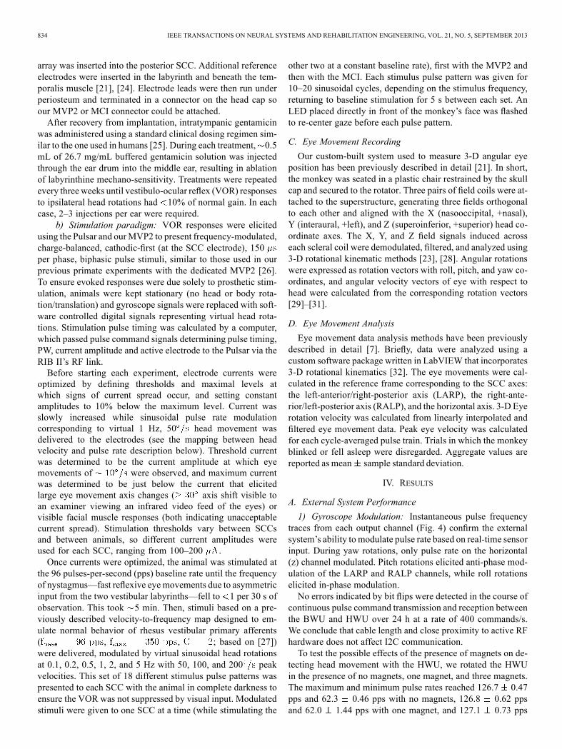
To verify functionality of the internal system, we used thePulsar IS (Med-El), a ceramic encased IS that functions inthe same way as the Concerto IS (which replaced the Pulsarin later design iterations). The Pulsar IS was controlled via a
Fig. 3. Setup used to test performance of the internal system. A com-puter sinusoidally modulated virtual head rotations and calculated timing ofpulse commands, which were sent to the implanted stimulator via the re-search interface box’s (RIBII) inductive link. Frequency-modulated biphasiccharge-balanced pulses were delivered to each of the monkey’s semicir-cular canals.
Research Interface Box II (RIB II; Leopold-Franzens-Univer-sity of Innsbruck, Austria [20]) (Fig. 3). We used this sep-arate setup to test the internal system performance due toproprietary restrictions on the RF design associated with theMed-El hardware.1) Current AmplitudeMeasurements: Prior to animal testing,
the current delivered by the Pulsar and by our lab-built MVP2weremeasured on a test-bench using a sense resistor wired in se-ries with a Teflon-coated steel wire (Cooner Wire, Chatsworth,CA, USA) submerged in 0.9% NaCl saline.2) In vivo Physiological Studies: Studies were performed on
two rhesus monkeys (F20124RhB and F060738RhG, referredto as monkey A and monkey B respectively; Macaca mulatta;5–12 kg) under a protocol approved by the Johns Hopkins An-imal Care and Use Committee, which is accredited by the As-sociation for the Assessment and Accreditation of LaboratoryAnimal Care, and consistent with European Community Direc-tive 86/609/EEC. The purpose of these experiments was to test ifthe MCI can deliver stimulation pulse trains evoking responsessimilar to those elicited with the MVP2.
a) Surgery: Each animal was implanted with 1) an acrylichead cap surgically affixed to the skull to aid in stereotaxicplacement during experiments, 2) two scleral coils for 3-D mea-surement of eye movements, and 3) an array of electrodes in-serted into the left ampullae. Vestibular function was ablatedvia intratympanic injection of gentamicin. Procedures were per-formed under sterile conditions and 1.5%–5% isoflurane anes-thesia.Surgical methods of head-cap, scleral coil, and electrode
implantation have been previously described [18], [21]–[23].In brief, a light poly-ether-ether-ketone head cap was firstaffixed to the animal’s skull using titanium bone screws. Then,two polytetrafluoro-ethylene-coated steel wire (Cooner Wire,Chatsworth, CA, USA) search coils were sutured to the scleraof each eye—one around the iris and another roughly orthog-onal to the first-, and wires were run to the connectors withinthe head cap. In a separate surgical session, electrodes wereimplanted into the left labyrinth. First, a mastoidectomy wasperformed, followed by exposure of the SCCs, each of whichwas then opened near the junction of the thin segment and theampulla. The forked electrode array was inserted near the junc-tion of the superior and horizontal SCCs, and the single-tine
834 IEEE TRANSACTIONS ON NEURAL SYSTEMS AND REHABILITATION ENGINEERING, VOL. 21, NO. 5, SEPTEMBER 2013
array was inserted into the posterior SCC. Additional referenceelectrodes were inserted in the labyrinth and beneath the tem-poralis muscle [21], [24]. Electrode leads were then run underperiosteum and terminated in a connector on the head cap soour MVP2 or MCI connector could be attached.After recovery from implantation, intratympanic gentamicin
was administered using a standard clinical dosing regimen sim-ilar to the one used in humans [25]. During each treatment, 0.5mL of 26.7 mg/mL buffered gentamicin solution was injectedthrough the ear drum into the middle ear, resulting in ablationof labyrinthine mechano-sensitivity. Treatments were repeatedevery three weeks until vestibulo-ocular reflex (VOR) responsesto ipsilateral head rotations had 10% of normal gain. In eachcase, 2–3 injections per ear were required.
b) Stimulation paradigm: VOR responses were elicitedusing the Pulsar and ourMVP2 to present frequency-modulated,charge-balanced, cathodic-first (at the SCC electrode), 150per phase, biphasic pulse stimuli, similar to those used in ourprevious primate experiments with the dedicated MVP2 [26].To ensure evoked responses were due solely to prosthetic stim-ulation, animals were kept stationary (no head or body rota-tion/translation) and gyroscope signals were replaced with soft-ware controlled digital signals representing virtual head rota-tions. Stimulation pulse timing was calculated by a computer,which passed pulse command signals determining pulse timing,PW, current amplitude and active electrode to the Pulsar via theRIB II’s RF link.Before starting each experiment, electrode currents were
optimized by defining thresholds and maximal levels atwhich signs of current spread occur, and setting constantamplitudes to 10% below the maximum level. Current wasslowly increased while sinusoidal pulse rate modulationcorresponding to virtual 1 Hz, 50 head movement wasdelivered to the electrodes (see the mapping between headvelocity and pulse rate description below). Threshold currentwas determined to be the current amplitude at which eyemovements of were observed, and maximum currentwas determined to be just below the current that elicitedlarge eye movement axis changes ( axis shift visible toan examiner viewing an infrared video feed of the eyes) orvisible facial muscle responses (both indicating unacceptablecurrent spread). Stimulation thresholds vary between SCCsand between animals, so different current amplitudes wereused for each SCC, ranging from 100–200 .Once currents were optimized, the animal was stimulated at
the 96 pulses-per-second (pps) baseline rate until the frequencyof nystagmus—fast reflexive eye movements due to asymmetricinput from the two vestibular labyrinths—fell to 1 per 30 s ofobservation. This took 5 min. Then, stimuli based on a pre-viously described velocity-to-frequency map designed to em-ulate normal behavior of rhesus vestibular primary afferents( , , ; based on [27])were delivered, modulated by virtual sinusoidal head rotationsat 0.1, 0.2, 0.5, 1, 2, and 5 Hz with 50, 100, and 200 peakvelocities. This set of 18 different stimulus pulse patterns waspresented to each SCC with the animal in complete darkness toensure the VOR was not suppressed by visual input. Modulatedstimuli were given to one SCC at a time (while stimulating the
other two at a constant baseline rate), first with the MVP2 andthen with the MCI. Each stimulus pulse pattern was given for10–20 sinusoidal cycles, depending on the stimulus frequency,returning to baseline stimulation for 5 s between each set. AnLED placed directly in front of the monkey’s face was flashedto re-center gaze before each pulse pattern.
C. Eye Movement Recording
Our custom-built system used to measure 3-D angular eyeposition has been previously described in detail [21]. In short,the monkey was seated in a plastic chair restrained by the skullcap and secured to the rotator. Three pairs of field coils were at-tached to the superstructure, generating three fields orthogonalto each other and aligned with the X (nasooccipital, +nasal),Y (interaural, +left), and Z (superoinferior, +superior) head co-ordinate axes. The X, Y, and Z field signals induced acrosseach scleral coil were demodulated, filtered, and analyzed using3-D rotational kinematic methods [23], [28]. Angular rotationswere expressed as rotation vectors with roll, pitch, and yaw co-ordinates, and angular velocity vectors of eye with respect tohead were calculated from the corresponding rotation vectors[29]–[31].
D. Eye Movement Analysis
Eye movement data analysis methods have been previouslydescribed in detail [7]. Briefly, data were analyzed using acustom software package written in LabVIEW that incorporates3-D rotational kinematics [32]. The eye movements were cal-culated in the reference frame corresponding to the SCC axes:the left-anterior/right-posterior axis (LARP), the right-ante-rior/left-posterior axis (RALP), and the horizontal axis. 3-D Eyerotation velocity was calculated from linearly interpolated andfiltered eye movement data. Peak eye velocity was calculatedfor each cycle-averaged pulse train. Trials in which the monkeyblinked or fell asleep were disregarded. Aggregate values arereported as mean sample standard deviation.
IV. RESULTS
A. External System Performance
1) Gyroscope Modulation: Instantaneous pulse frequencytraces from each output channel (Fig. 4) confirm the externalsystem’s ability to modulate pulse rate based on real-time sensorinput. During yaw rotations, only pulse rate on the horizontal(z) channel modulated. Pitch rotations elicited anti-phase mod-ulation of the LARP and RALP channels, while roll rotationselicited in-phase modulation.No errors indicated by bit flips were detected in the course of
continuous pulse command transmission and reception betweenthe BWU and HWU over 24 h at a rate of 400 commands/s.We conclude that cable length and close proximity to active RFhardware does not affect I2C communication.To test the possible effects of the presence of magnets on de-
tecting head movement with the HWU, we rotated the HWUin the presence of no magnets, one magnet, and three magnets.The maximum and minimum pulse rates reached 126.7 0.47pps and 62.3 0.46 pps with no magnets, 126.8 0.62 ppsand 62.0 1.44 pps with one magnet, and 127.1 0.73 pps
VALENTIN et al.: DEVELOPMENT OF A MULTICHANNEL VESTIBULAR PROSTHESIS PROTOTYPE 835
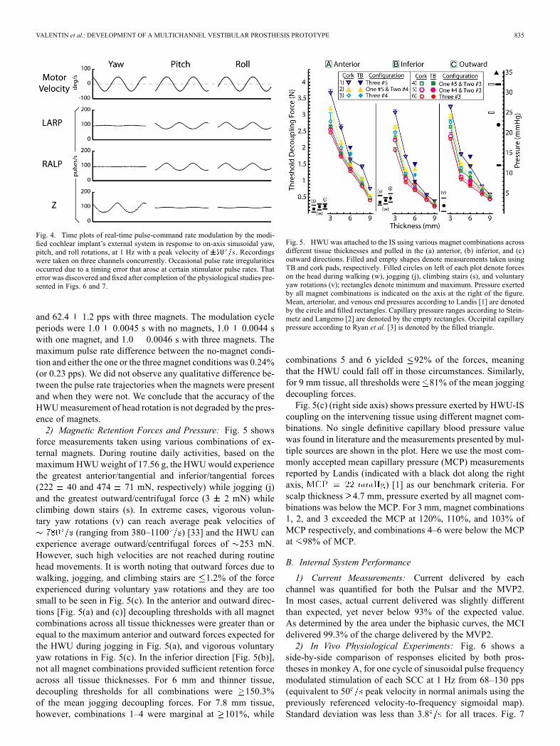
Fig. 4. Time plots of real-time pulse-command rate modulation by the modi-fied cochlear implant’s external system in response to on-axis sinusoidal yaw,pitch, and roll rotations, at 1 Hz with a peak velocity of . Recordingswere taken on three channels concurrently. Occasional pulse rate irregularitiesoccurred due to a timing error that arose at certain stimulator pulse rates. Thaterror was discovered and fixed after completion of the physiological studies pre-sented in Figs. 6 and 7.
and 62.4 1.2 pps with three magnets. The modulation cycleperiods were 1.0 0.0045 s with no magnets, 1.0 0.0044 swith one magnet, and 1.0 0.0046 s with three magnets. Themaximum pulse rate difference between the no-magnet condi-tion and either the one or the three magnet conditions was 0.24%(or 0.23 pps). We did not observe any qualitative difference be-tween the pulse rate trajectories when the magnets were presentand when they were not. We conclude that the accuracy of theHWUmeasurement of head rotation is not degraded by the pres-ence of magnets.2) Magnetic Retention Forces and Pressure: Fig. 5 shows
force measurements taken using various combinations of ex-ternal magnets. During routine daily activities, based on themaximum HWUweight of 17.56 g, the HWUwould experiencethe greatest anterior/tangential and inferior/tangential forces(222 40 and 474 71 mN, respectively) while jogging (j)and the greatest outward/centrifugal force (3 2 mN) whileclimbing down stairs (s). In extreme cases, vigorous volun-tary yaw rotations (v) can reach average peak velocities of
(ranging from 380–1100 ) [33] and the HWU canexperience average outward/centrifugal forces of 253 mN.However, such high velocities are not reached during routinehead movements. It is worth noting that outward forces due towalking, jogging, and climbing stairs are 1.2% of the forceexperienced during voluntary yaw rotations and they are toosmall to be seen in Fig. 5(c). In the anterior and outward direc-tions [Fig. 5(a) and (c)] decoupling thresholds with all magnetcombinations across all tissue thicknesses were greater than orequal to the maximum anterior and outward forces expected forthe HWU during jogging in Fig. 5(a), and vigorous voluntaryyaw rotations in Fig. 5(c). In the inferior direction [Fig. 5(b)],not all magnet combinations provided sufficient retention forceacross all tissue thicknesses. For 6 mm and thinner tissue,decoupling thresholds for all combinations were 150.3%of the mean jogging decoupling forces. For 7.8 mm tissue,however, combinations 1–4 were marginal at 101%, while
Fig. 5. HWU was attached to the IS using various magnet combinations acrossdifferent tissue thicknesses and pulled in the (a) anterior, (b) inferior, and (c)outward directions. Filled and empty shapes denote measurements taken usingTB and cork pads, respectively. Filled circles on left of each plot denote forceson the head during walking (w), jogging (j), climbing stairs (s), and voluntaryyaw rotations (v); rectangles denote minimum and maximum. Pressure exertedby all magnet combinations is indicated on the axis at the right of the figure.Mean, arteriolar, and venous end pressures according to Landis [1] are denotedby the circle and filled rectangles. Capillary pressure ranges according to Stein-metz and Langemo [2] are denoted by the empty rectangles. Occipital capillarypressure according to Ryan et al. [3] is denoted by the filled triangle.
combinations 5 and 6 yielded 92% of the forces, meaningthat the HWU could fall off in those circumstances. Similarly,for 9 mm tissue, all thresholds were 81% of the mean joggingdecoupling forces.Fig. 5(c) (right side axis) shows pressure exerted by HWU-IS
coupling on the intervening tissue using different magnet com-binations. No single definitive capillary blood pressure valuewas found in literature and the measurements presented by mul-tiple sources are shown in the plot. Here we use the most com-monly accepted mean capillary pressure (MCP) measurementsreported by Landis (indicated with a black dot along the rightaxis, ) [1] as our benchmark criteria. Forscalp thickness 4.7 mm, pressure exerted by all magnet com-binations was below the MCP. For 3 mm, magnet combinations1, 2, and 3 exceeded the MCP at 120%, 110%, and 103% ofMCP respectively, and combinations 4–6 were below the MCPat 98% of MCP.
B. Internal System Performance
1) Current Measurements: Current delivered by eachchannel was quantified for both the Pulsar and the MVP2.In most cases, actual current delivered was slightly differentthan expected, yet never below 93% of the expected value.As determined by the area under the biphasic curves, the MCIdelivered 99.3% of the charge delivered by the MVP2.2) In Vivo Physiological Experiments: Fig. 6 shows a
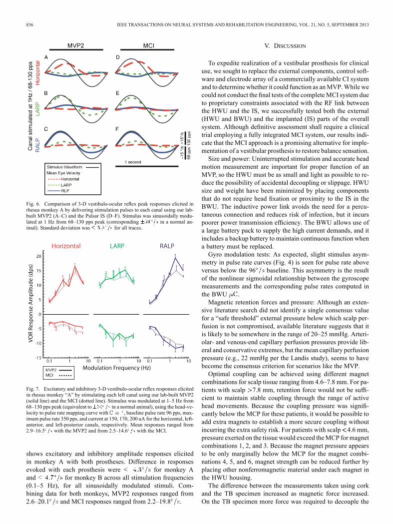
side-by-side comparison of responses elicited by both pros-theses in monkey A, for one cycle of sinusoidal pulse frequencymodulated stimulation of each SCC at 1 Hz from 68–130 pps(equivalent to 50 peak velocity in normal animals using thepreviously referenced velocity-to-frequency sigmoidal map).Standard deviation was less than 3.8 for all traces. Fig. 7
836 IEEE TRANSACTIONS ON NEURAL SYSTEMS AND REHABILITATION ENGINEERING, VOL. 21, NO. 5, SEPTEMBER 2013
Fig. 6. Comparison of 3-D vestibulo-ocular reflex peak responses elicited inrhesus monkey A by delivering stimulation pulses to each canal using our lab-built MVP2 (A–C) and the Pulsar IS (D–F). Stimulus was sinusoidally modu-lated at 1 Hz from 68–130 pps peak (corresponding in a normal an-imal). Standard deviation was for all traces.
Fig. 7. Excitatory and inhibitory 3-D vestibulo-ocular reflex responses elicitedin rhesus monkey “A” by stimulating each left canal using our lab-built MVP2(solid line) and the MCI (dotted line). Stimulus was modulated at 1–5 Hz from68–130 pps peak (equivalent to in a normal animal), using the head-ve-locity to pulse rate mapping curve with , baseline pulse rate 96 pps, max-imum pulse rate 350 pps, and current at 150, 170, 200 uA for the horizontal, left-anterior, and left-posterior canals, respectively. Mean responses ranged from2.9–16.5 with the MVP2 and from 2.5–14.6 with the MCI.
shows excitatory and inhibitory amplitude responses elicitedin monkey A with both prostheses. Difference in responsesevoked with each prosthesis were for monkey Aand for monkey B across all stimulation frequencies(0.1–5 Hz), for all sinusoidally modulated stimuli. Com-bining data for both monkeys, MVP2 responses ranged from2.6–20.1 and MCI responses ranged from 2.2–19.8 .
V. DISCUSSION
To expedite realization of a vestibular prosthesis for clinicaluse, we sought to replace the external components, control soft-ware and electrode array of a commercially available CI systemand to determinewhether it could function as anMVP.While wecould not conduct the final tests of the completeMCI system dueto proprietary constraints associated with the RF link betweenthe HWU and the IS, we successfully tested both the external(HWU and BWU) and the implanted (IS) parts of the overallsystem. Although definitive assessment shall require a clinicaltrial employing a fully integrated MCI system, our results indi-cate that the MCI approach is a promising alternative for imple-mentation of a vestibular prosthesis to restore balance sensation.Size and power: Uninterrupted stimulation and accurate head
motion measurement are important for proper function of anMVP, so the HWU must be as small and light as possible to re-duce the possibility of accidental decoupling or slippage. HWUsize and weight have been minimized by placing componentsthat do not require head fixation or proximity to the IS in theBWU. The inductive power link avoids the need for a percu-taneous connection and reduces risk of infection, but it incurspoorer power transmission efficiency. The BWU allows use ofa large battery pack to supply the high current demands, and itincludes a backup battery to maintain continuous function whena battery must be replaced.Gyro modulation tests: As expected, slight stimulus asym-
metry in pulse rate curves (Fig. 4) is seen for pulse rate aboveversus below the 96 baseline. This asymmetry is the resultof the nonlinear sigmoidal relationship between the gyroscopemeasurements and the corresponding pulse rates computed inthe BWU .Magnetic retention forces and pressure: Although an exten-
sive literature search did not identify a single consensus valuefor a “safe threshold” external pressure below which scalp per-fusion is not compromised, available literature suggests that itis likely to be somewhere in the range of 20–25 mmHg. Arteri-olar- and venous-end capillary perfusion pressures provide lib-eral and conservative extremes, but themean capillary perfusionpressure (e.g., 22 mmHg per the Landis study), seems to havebecome the consensus criterion for scenarios like the MVP.Optimal coupling can be achieved using different magnet
combinations for scalp tissue ranging from 4.6–7.8 mm. For pa-tients with scalp 7.8 mm, retention force would not be suffi-cient to maintain stable coupling through the range of activehead movements. Because the coupling pressure was signifi-cantly below the MCP for these patients, it would be possible toadd extra magnets to establish a more secure coupling withoutincurring the extra safety risk. For patients with scalp 4.6 mm,pressure exerted on the tissue would exceed theMCP formagnetcombinations 1, 2, and 3. Because the magnet pressure appearsto be only marginally below the MCP for the magnet combi-nations 4, 5, and 6, magnet strength can be reduced further byplacing other nonferromagnetic material under each magnet inthe HWU housing.The difference between the measurements taken using cork
and the TB specimen increased as magnetic force increased.On the TB specimen more force was required to decouple the

VALENTIN et al.: DEVELOPMENT OF A MULTICHANNEL VESTIBULAR PROSTHESIS PROTOTYPE 837
HWU likely due to the higher compressibility of the scalp whichallows the HWU to slightly dimple the tissue and resist greatertangential forces. All measurements taken with the human TBspecimen with scalp tissue 6 mm are well fit to the regressionlines defined by the cork data, being 532 mN away from theregression line in each case.One could convert the force data we report into torques by
arbitrarily specifying a center of rotation. We elected not to dothat because no single center of rotation sufficiently dominatesthe rotational motion experienced in activities of daily living.(One could choose the center of the head, but data would stillhave to be rescaled by the moment arm for rotation about anyother point.)In vivo stimulation: Data in Figs. 6 and 7 show that the MCI’s
implantable stimulator evokes responses in rhesus monkeyscomparable to those evoked with the MVP2 to partially restorethe 3-D VOR for head rotations about each SCC axis. However,some nonidealities were seen.First, LP canal stimulation yielded responses of greater mag-
nitude than the LA or LH canals. This could be due to the LPelectrode being closer to its target than other electrodes were totheirs.Second, an excitatory versus inhibitory asymmetry was seen
in the eye responses in Figs. 6 and 7. Asymmetry is an inherentfeature of VOR responses driven by a single normal ear [34]. Itis more apparent during prosthetic stimulation because pulsatilestimuli cannot depress vestibular nerve primary afferent fibers’firing rates below their spontaneous discharge rates. Stimulationprotocols in which subjects are allowed to adapt to supernormalbaseline rates during pulse frequency and amplitude “co-modu-lation” are effective in reducing asymmetry [35]. While we didnot explicitly test this stimulation strategy the MCI is fully ca-pable of implementing this protocol.Lastly, although responses were greater in the plane of the
stimulated SCC, spurious stimulation of nontarget nerves resultsin misalignment (i.e., eye movements do not precisely alignwith the 3-D axis of head rotation). This is likely due to currentspread.We previously showed that incorporating a pre-compen-satory 3-D coordinate transformation in the prosthesis can re-duce the misalignment [9]. Although the MCI’s HWU incorpo-rates a microcontroller similar to the one that implements thiscoordinate transformation protocol in the MVP2, we have notyet implemented that protocol in the MCI.Future directions: We tested external and internal systems
separately and verified their functionality. Efforts to combineboth systems into one complete, fully functional MCI are un-derway. Once this is accomplished, we intend to replicate re-sults obtained with our previous MVPs, implementing novelstimulation protocols and algorithms recently developed by ourlab to elicit more symmetric responses and improve misalign-ment [9], [35]. Results to date suggest that realization of thefirst human-implantable MVP for treatment of BVH is possibleusing this approach.
ACKNOWLEDGMENT
The authors gratefully acknowledge contributions of A.Jäger, R. Hessler, and A. Hofner (Med-El Elektromedizinische
Gerate GmbH; modified Concerto CI and associated hardware);E. Hochmair and O. Peter (University of Innsbruck; RIBII);N. Davidovics, M. Rahman, B. Chiang, B. Ward, J. Ho Ahn,and L. Swarthout (Johns Hopkins; analysis software, MVP2fabrication, editing, and animal care). C. Della Santina holdsan equity interest in and is CEO of Labyrinth Devices, LLC,a start-up company founded to support commercialization ofvestibular prosthesis technology. Terms of this arrangement aremanaged by the Johns Hopkins University in accordance withits conflict of interest policies.
REFERENCES
[1] E. Landis, “Micro-injection studies of capillary blood pressure inhuman skin,” Heart, vol. 15, 1930.
[2] J. A. Steinmetz and D. K. Langemo, “Changes in occipital capillaryperfusion pressures during coronary artery bypass graft surgery,” Adv.Wound Care, vol. 9, no. 3, pp. 28–32, May–Jun. 1996.
[3] D. Ryan, V. Allen, and A. Murray, “An investigation of interface pres-sures in low air loss beds,” Int. J. Clin. Pract., vol. 51, no. 5, pp.296–298, 1997.
[4] C. C. Della Santina, A. A. Migliaccio, R. Hayden, T. A. Melvin, G. Y.Fridman, B. Chiang, N. S. Davidovics, C. Dai, J. P. Carey, L. B. Minor,I. C. Anderson, H. Park, S. Lyford-Pike, and S. Tang, “Current andfuture management of bilateral loss of vestibular sensation—An up-date on the Johns Hopkins multichannel vestibular prosthesis project,”Cochlear Implants Int., vol. 11, no. Suppl 2, pp. 2–11, Sep. 2010.
[5] M. A. Rahman, C. Dai, G. Y. Fridman, N. S. Davidovics, B. Chiang,J. Ahn, R. Hayden, T. A. Melvin, D. Q. Sun, A. Hedjoudje, and C.C. Della Santina, “Restoring the 3-D vestibulo-ocular reflex via elec-trical stimulation: The Johns Hopkins multichannel vestibular pros-thesis project,” in Proc. IEEE Eng. Med. Biol. Soc. Conf., 2011, vol.2011, pp. 3142–3145.
[6] C. Dai, G. Y. Fridman, B. Chiang, N. S. Davidovics, T. A. Melvin, K.E. Cullen, and C. C. Della Santina, “Cross-axis adaptation improves3-D vestibulo-ocular reflex alignment during chronic stimulation viaa head-mounted multichannel vestibular prosthesis,” Exp. Brain Res.,vol. 210, no. 3–4, pp. 595–606, May 2011.
[7] N. S. Davidovics, G. Y. Fridman, B. Chiang, and C. C. Della Santina,“Effects of biphasic current pulse frequency, amplitude, duration, inter-phase gap on eye movement responses to prosthetic electrical stimula-tion of the vestibular nerve,” IEEE Trans. Neural Syst. Rehabil. Eng.,vol. 19, no. 1, pp. 84–94, Feb. 2011.
[8] D. Q. Sun, M. A. Rahman, G. Fridman, C. Dai, B. Chiang, and C. C.Della Santina, “Chronic stimulation of the semicircular canals using amultichannel vestibular prosthesis: Effects on locomotion and angularvestibulo-ocular reflex in chinchillas,” in Proc IEEE Eng. Med. Biol.Soc. Conf., 2011, vol. 2011, pp. 3519–3523.
[9] G. Y. Fridman, N. S. Davidovics, C. Dai, A. A. Migliaccio, and C.C. Della Santina, “Vestibulo-ocular reflex responses to a multichannelvestibular prosthesis incorporating a 3-D coordinate transformation forcorrection of misalignment,” J. Assoc. Res. Otolaryngol., vol. 11, no.3, pp. 367–381, Sep. 2010.
[10] W. Gong and D. M. Merfeld, “Prototype neural semicircular canalprosthesis using patterned electrical stimulation,” Ann. Biomed. Eng.,vol. 28, no. 5, pp. 572–581, May 2000.
[11] C. C. Della Santina, A. A.Migliaccio, and A. H. Patel, “Amultichannelsemicircular canal neural prosthesis using electrical stimulation to re-store 3-d vestibular sensation,” IEEE Trans. Biomed. Eng., vol. 54, no.6, pp. 1016–1030, Jun. 2007.
[12] C. Della Santina, A. Migliaccio, and A. Patel, “Electrical stimulation torestore vestibular function development of a 3-d vestibular prosthesis,”in Proc. IEEE Eng. Med. Biol. Soc. Conf., 2005, vol. 7, pp. 7380–7385.
[13] C. Wall, M. I. Kos, and J. P. Guyot, “Eye movements in responseto electric stimulation of the human posterior ampullary nerve,” Ann.Otol. Rhinol. Laryngol., vol. 116, no. 5, pp. 369–374, May 2007.
[14] J. T. Rubinstein, J. Phillips, K. Nai, L. Ling, S. Bierer, E. Jameson,and T. Oxford, “Clinical, scientific, regulatory roadmap for a humanvestibular implant,” presented at the ARO 2011 Midwinter Meet., Bal-timore, MD.

838 IEEE TRANSACTIONS ON NEURAL SYSTEMS AND REHABILITATION ENGINEERING, VOL. 21, NO. 5, SEPTEMBER 2013
[15] J. P. Guyot, A. Sigrist, M. Pelizzone, and M. I. Kos, “Adaptation tosteady-state electrical stimulation of the vestibular system in humans,”Ann. Otol. Rhinol. Laryngol., vol. 120, no. 3, pp. 143–149, Mar. 2011.
[16] J. P. Guyot, A. Sigrist, M. Pelizzone, G. C. Feigl, and M. I. Kos, “Eyemovements in response to electrical stimulation of the lateral and su-perior ampullary nerves,” Ann. Otol. Rhinol. Laryngol., vol. 120, no.2, pp. 81–87, Feb. 2011.
[17] D. Lasker and M. Schubert, “3-D measurement of linear accelerationsand angular velocities of the head, torso and leg during natural activ-ities,” presented at the ARO 35th Annu. Midwinter Res. Meet., SanDiego, CA, 2012.
[18] B. Chiang, G. Y. Fridman, C. Dai, M. A. Rahman, and C. C. DellaSantina, “Design and performance of a multichannel vestibular pros-thesis that restores semicircular canal sensation in rhesus monkey,”IEEE Trans. Neural Syst. Rehabil. Eng., vol. 19, no. 5, pp. 588–598,Oct. 2011.
[19] C. H. Raine, C. A. Lee, D. R. Strachan, C. T. Totten, and S. Khan,“Skin flap thickness in cochlear implant patients—A prospectivestudy,” Cochlear Implants Int., vol. 8, no. 3, pp. 148–157, Sep. 2007.
[20] A. Bahmer, O. Peter, and U. Baumann, “Recording and analysisof electrically evoked compound action potentials (ECAPs) withMED-EL cochlear implants and different artifact reduction strategiesin Matlab,” J. Neurosci. Methods, vol. 191, no. 1, pp. 66–74, Aug.2010.
[21] A. A. Migliaccio, M. C. Schubert, P. Jiradejvong, D. M. Lasker, R. A.Clendaniel, and L. B. Minor, “The three-dimensional vestibulo-ocularreflex evoked by high-acceleration rotations in the squirrel monkey,”Exp. Brain Res., vol. 159, no. 4, pp. 433–446, Dec. 2004.
[22] R. A. Clendaniel, D. M. Lasker, and L. B. Minor, “Horizontal vestibu-loocular reflex evoked by high-acceleration rotations in the squirrelmonkey. IV. Responses after spectacle-induced adaptation,” J. Neu-rophysiol., vol. 86, no. 4, pp. 1594–1611, Oct. 2001.
[23] D. A. Robinson, “Amethod of measuring eyemovement using a scleralsearch coil in a magnetic field,” IEEE Trans. Biomed. Eng., vol. 10, pp.137–145, Oct. 1963.
[24] C. Dai, G. Y. Fridman, and C. C. Della Santina, “Effects ofvestibular prosthesis electrode implantation and stimulation onhearing in rhesus monkeys,” Hear. Res., vol. 277, no. 1–2,pp. 204–210, Jul. 2011.
[25] L. B. Minor, “Intratympanic gentamicin for control of vertigo in Me-niere’s disease: Vestibular signs that specify completion of therapy,”Am. J. Otol., vol. 20, no. 2, pp. 209–219, Mar. 1999.
[26] C. Dai, G. Y. Fridman, N. S. Davidovics, B. Chiang, J. H. Ahn, andC. C. Della Santina, “Restoration of 3-D vestibular sensation in rhesusmonkeys using a multichannel vestibular prosthesis,” Hear. Res., vol.281, no. 1–2, pp. 74–83, Nov. 2011.
[27] S. G. Sadeghi, L. B. Minor, and K. E. Cullen, “Dynamics of thehorizontal vestibuloocular reflex after unilateral labyrinthectomy: Re-sponse to high frequency, high acceleration, high velocity rotations,”Exp. Brain Res., vol. 175, no. 3, pp. 471–484, Nov. 2006.
[28] D. Straumann, “The validity of oculomotor laws,” Schweiz Arch.Neurol. Psychiatr., vol. 146, no. 4, pp. 151–156, 1995.
[29] T. Haslwanter, “Mathematics of three-dimensional eye rotations,” Vi-sion Res, vol. 35, no. 12, pp. 1727–1739, Jun. 1995.
[30] A. A. Migliaccio and M. J. Todd, “Real-time rotation vectors,” Aus-tralas Phys. Eng. Sci. Med., vol. 22, no. 2, pp. 73–80, Jun. 1999.
[31] K. Hepp, “On Listing’s law,” Commun. Math. Phys., vol. 132, pp.285–295, 1990.
[32] A. A. Migliaccio, C. C. Della Santina, J. P. Carey, J. K. Niparko, andL. B. Minor, “The vestibulo-ocular reflex response to head impulsesrarely decreases after cochlear implantation,” Otol. Neurotol., vol. 26,no. 4, pp. 655–660, Jul. 2005.
[33] G. E. Grossman, R. J. Leigh, L. A. Abel, D. J. Lanska, and S. E.Thurston, “Frequency and velocity of rotational head perturbationsduring locomotion,” Exp. Brain Res., vol. 70, no. 3, pp. 470–476,1988.
[34] J. R. Ewald, Physiologische Untersuchungen uber das EndorgandesNervus Octavus. Wiesbaden, Germany: Nabu, 1892.
[35] N. S. Davidovics, G. Y. Fridman, and C. C. Della Santina, “Co-mod-ulation of stimulus rate and current from elevated baselines expandshead motion encoding range of the vestibular prosthesis,” Exp. BrainRes., vol. 218, no. 3, pp. 389–400, May 2012.
[36] C. Garnham, M. Zimmerling, and A. Jäger, “Vestibular implant systemwith internal and external motion sensors,” U.S. Patent 0 022 616 A1,2012.
[37] J. O. Phillips, S. J. Shepherd, A. L. Nowack, L. Ling, S. M. Bierer, C.R. S. Kaneko, C. M. T. Phillips, K. Nie, and J. T. Rubinstein, “Longitu-dinal performance of a vestibular prosthesis as assessed by electricallyevoked compound action potential recording,” inProc. Annu. Int. Conf.IEEE Eng. Med. Biol. Soc., 2012, pp. 6128–6131.
[38] K. Nie, L. Ling, S. Bierer, C. Kaneko, A. Fuchs, T. Oxford, J. Rubin-stein, and J. Phillips, “An experimental vestibular neural prosthesis:Design and preliminary results with rhesus monkeys stimulated withmodulated pulses,” IEEE Trans. Biomed. Eng., vol. 60, no. 6, pp. 1685–1692, Jun. 2013.
[39] T. G. Constandinou, J. Georgiou, and C. Toumazou, “A partial-current-steering biphasic stimulation driver for vestibular prostheses,” IEEETrans. Biomed. Circuits Syst., vol. 2, no. 2, pp. 106–113, Jun. 2008.
[40] J. Dai, A. Demosthenous, T. Perkins, X. Liu, and N. Donaldson, “Astimulator ASIC featuring versatile management for vestibular pros-theses,” IEEE Trans. Biomed. Circuits Syst., vol. 5, no. 2, pp. 147–159,Apr. 2011.
[41] S. Micera, J. DiGiovanna, A. Berthoz, A. Demosthenous, J. Guyot, K.Hoffmann, D. Merfeld, and M. Morari, “A closed-loop neural pros-thesis for vestibular disorders,” in Proc. 10th Symp. Neural Netw. Appl.Electr. Eng., Sep. 23–25, 2010, pp. 27–30.
Nicolas S. Valentin was born in Bogotá, Colombia.He received the B.S. degree in electrical engineeringfrom the California State Polytechnic University,Pomona, CA, USA, in 2009, and the M.S. degreein biomedical engineering from Johns Hopkins Uni-versity, Baltimore, MD, USA, in 2012. His graduateresearch work in the Vestibular NeuroengineeringLaboratory at Johns Hopkins University focusedon the development of a multichannel prosthesisprototype for restoration of vestibular function.He is currently a Systems Engineer for Labyrinth
Devices, Baltimore, MD, USA, working on the design and commercializationof the human-implantable vestibular prosthesis.
Kristin N. Hageman received the B.S. degree inbiomedical engineering from Case Western Re-serve University, Cleveland, OH, USA, in 2011,with a specialty in bioelectrical engineering. Sheis currently working toward the Ph.D. degree inbiomedical engineering at Johns Hopkins UniversitySchool of Medicine, Baltimore, MD, USA. Herresearch in the Vestibular NeuroEngineering Labfocuses on the circuit development of the nextgeneration multichannel vestibular prosthesis.
Chenkai Dai received the M.D. and M.S. degreesfrom Tongji Medical College, Huazhong Uni-versity of Science and Technology, Wuhan, China(1995–2003), and the Ph.D. degree in bioengineeringfrom the University of Oklahoma, Norman, OK,USA, in 2008, where his research focused on middleear mechanics.He is a Research Associate in the Department of
Otolaryngology-Head and Neck Surgery at the JohnsHopkins School of Medicine, Baltimore, MD, USA.His current research focuses on vestibular neurophys-
iology and on assessment and refinement of vestibular prosthesis technology inalert, behaving animals.
VALENTIN et al.: DEVELOPMENT OF A MULTICHANNEL VESTIBULAR PROSTHESIS PROTOTYPE 839
Charles C. Della Santina received the Ph.D. degreein bioengineering, in 1994, from the University ofCalifornia, Berkeley, CA, USA, where his work fo-cused on development of micromachined silicon de-vices for chronic multi-unit interfacing to the audi-tory/vestibular nerve, and the M.D. degree from theUniversity of California, San Francisco, CA, USA, in1997. He completed residency at the Johns HopkinsSchool of Medicine, Baltimore, MD, USA, in 2002.He has been a clinician-scientist at Johns Hopkins,
where he is Director of the Johns Hopkins VestibularNeuroEngineering Lab and a Professor of Otolaryngology—Head & neckSurgery and Biomedical Engineering. His research focuses on vestibularneurophysiology and development of a vestibular prosthesis for restoration oflabyrinthine sensation. He holds a founding interest in Labyrinth Devices LLC.
Gene Y. Fridman (M’13) received the B.S. degreein computer engineering from The University ofKansas, Lawrence, KS, USA, in 1992, the M.S.degree in electrical engineering from Purdue Uni-versity, West Lafayette, IN, USA, in 1995, andthe Ph.D. degree in biomedical engineering, spe-cializing in neural recording and stimulation, andmicro-electro-mechanical systems from the Univer-sity of California, Los Angeles, CA, USA, in 2006,and then completed postdoctoral training at JohnsHopkins University, Baltimore, MD, USA, in 2009.
Prior to receiving the Ph.D. degree, he worked in the industry for five yearsin R&D as software and systems engineer before deciding to engage in an aca-demic career. He is an Assistant Professor of Otolaryngology Head and NeckSurgery at the Johns Hopkins School of Medicine. His research focuses on stim-ulation and recording interaction with the nervous system for the innovation andimprovement of the neuro-electronic prostheses including cortical, cochlear,and vestibular implants.
Related Documents