Sensors 2015, 15, 3610-3624; doi:10.3390/s150203610 OPEN ACCESS sensors ISSN 1424-8220 www.mdpi.com/journal/sensors Article Development of a Moisture-in-Solid-Insulation Sensor for Power Transformers Belén García 1, *, Diego García 2 and Guillermo Robles 1 1 Department of Electrical Engineering, Universidad Carlos III de Madrid, Avda de la Universidad 30, Leganés, Madrid 28911, Spain 2 School of Electrical and Electronic Engineering, Edificio 356 - Ciudad Universitaria, Meléndez, Calle 13 No 100-00, Cali 760032, Colombia * Author to whom correspondence should be addressed; E-Mail: [email protected]; Tel.: +34-91-6249-949; Fax: +34-91-6249-430. Academic Editor: Vittorio M.N. Passaro Received: 23 December 2014 / Accepted: 22 January 2015 / Published: 4 February 2015 Abstract: Moisture is an important variable that must be kept under control to guarantee a safe operation of power transformers. Because of the hydrophilic character of cellulose, water mainly remains in the solid insulation, while just a few parts per million are dissolved in oil. The distribution of moisture between paper and oil is not static, but varies depending on the insulation temperature, and thus, water migration processes take place continuously during transformers operation. In this work, a sensor is presented that allows the determination of the moisture content of the transformer solid insulation in the steady state and during the moisture migration processes. The main objective of the design is that the electrodes of the sensor should not obstruct the movement of water from the solid insulation to the oil, so the proposed prototype uses a metallic-mesh electrode to do the measurements. The measurement setup is based on the characterization of the insulation dielectric response by means of the frequency dielectric spectroscopy (FDS) method. The sensitivity of the proposed sensor has been tested on samples with a moisture content within 1% to 5%, demonstrating the good sensitivity and repeatability of the measurements. Keywords: dielectric response; power transformer; moisture; solid insulation; moisture sensor; FDS; moisture monitoring

Welcome message from author
This document is posted to help you gain knowledge. Please leave a comment to let me know what you think about it! Share it to your friends and learn new things together.
Transcript
Sensors 2015, 15, 3610-3624; doi:10.3390/s150203610OPEN ACCESS
sensorsISSN 1424-8220
www.mdpi.com/journal/sensors
Article
Development of a Moisture-in-Solid-Insulation Sensor forPower TransformersBelén García 1,*, Diego García 2 and Guillermo Robles 1
1 Department of Electrical Engineering, Universidad Carlos III de Madrid, Avda de la Universidad 30,Leganés, Madrid 28911, Spain
2 School of Electrical and Electronic Engineering, Edificio 356 - Ciudad Universitaria, Meléndez,Calle 13 No 100-00, Cali 760032, Colombia
* Author to whom correspondence should be addressed; E-Mail: [email protected];Tel.: +34-91-6249-949; Fax: +34-91-6249-430.
Academic Editor: Vittorio M.N. Passaro
Received: 23 December 2014 / Accepted: 22 January 2015 / Published: 4 February 2015
Abstract: Moisture is an important variable that must be kept under control to guarantee asafe operation of power transformers. Because of the hydrophilic character of cellulose,water mainly remains in the solid insulation, while just a few parts per million aredissolved in oil. The distribution of moisture between paper and oil is not static, but variesdepending on the insulation temperature, and thus, water migration processes take placecontinuously during transformers operation. In this work, a sensor is presented that allowsthe determination of the moisture content of the transformer solid insulation in the steadystate and during the moisture migration processes. The main objective of the design isthat the electrodes of the sensor should not obstruct the movement of water from the solidinsulation to the oil, so the proposed prototype uses a metallic-mesh electrode to do themeasurements. The measurement setup is based on the characterization of the insulationdielectric response by means of the frequency dielectric spectroscopy (FDS) method. Thesensitivity of the proposed sensor has been tested on samples with a moisture content within1% to 5%, demonstrating the good sensitivity and repeatability of the measurements.
Keywords: dielectric response; power transformer; moisture; solid insulation; moisturesensor; FDS; moisture monitoring
Sensors 2015, 15 3611
1. Introduction
Power transformer reliability is essential for the adequate operation of power systems. Some of themain causes of transformer failures are related to their electrical insulation. These failures usually resultin huge economical costs for the electric companies in terms of damage to infrastructure and penalizationfor interruptions of the electricity supply [1].
Water is one of the most damaging agents for transformer cellulosic insulation. Its presence increasesthe aging rate of the insulation, reduces its dielectric margin and decreases the partial discharge inceptionvoltage [2]. These phenomena increase the probability of unexpected failures, so being able to estimatethe water content of transformer solid insulation is highly desirable to make adequate decisions relatedto maintenance operations, as well as to predict potential failure conditions [3,4].
Different methodologies have been proposed to determine the moisture content of transformer solidinsulation. Some of them are based on the use of equilibrium charts [5–7], which allow the estimationof the water content of the solid insulation if the temperature and the water content of oil are known.However, IEEE Standard C57.106.2006 discourages the use of this kind of direct calculation, as thecharts are only valid under equilibrium conditions, and their use might lead to errors in the estimation ofmoisture of up to 200% [8].
Several authors propose the use of oil-moisture probes combined with mathematical models tocharacterize the dynamics of the water exchange between paper and oil [9–12]. These models canprovide a good estimation of the moisture on the surface of the solid insulation; however, not so preciseinformation of the moisture in the inner part of the insulation can be obtained by using them. It mustbe considered that the time constants of water-migration between paper and oil are much longer that thethermal cycles inside the transformer, and as a consequence, the water on the surface of the paper mainlyparticipates in the exchange.
Alternatively, the methods based on the determination of the dielectric response of the transformerinsulation have been pointed out by Cigre as the most suitable to assess the moisture content of paperand pressboard [13]. Dielectric response methods are founded on the fact that when a dielectric materialis subjected to an electric field, its elemental dipoles are oriented in the direction of the field. Dipoleorientation is not instantaneous, but has a certain delay. The so-called dielectric response function,which characterizes the polarization transient, depends on different aspects, such as the material natureor the geometry of the object under study, but it also depends on the water content it contains.
Different measuring schemes might be currently used to obtain the dielectric response of the insulationin the time or the frequency domains, and commercial equipment is available to be used in the field.These techniques are accurate and lead to reliable estimations of the average moisture content of thesolid insulation. However, they should be applied off-line, since the current measuring schemes involveshort circuiting the transformer windings to be used as electrodes.
In this paper, a capacitive sensor is proposed to determine the moisture content of the transformersolid insulation while the transformer is in service. The difference of the proposed scheme with regardto classical approaches is that, in this case, the measurements are done on a test object composed ofKraft paper. The test object is fit inside the transformer tank, where it is subjected to temperature profilessimilar to those of transformer solid insulation, and as a consequence, it describes a moisture dynamics
Sensors 2015, 15 3612
similar to that of transformer solid insulation. The dielectric response of the object is measured todetermine its moisture content, and this indication is used to estimate the distribution of moisture of thetransformer solid insulation.
To define the geometry of the sensor, it is important to consider that the migration of moisture betweenpaper and oil should not be obstructed by the plates of the capacitive probe. To this aim, a metallic meshis used as the external electrode, while a solid core of steel is used as the inner electrode of the capacitor.
The advantage of the presented measuring scheme is that it allows having a continuous measurementof the water content of the solid insulation. The sensor is not proposed to be an alternative to the off-linedielectric measurements, but to complement the information provided by them between transformerdischarges. The new measuring scheme could also be used during moisture dynamics experiments,which are usually very complex and time consuming when the traditional methods based on periodicaldirect determinations of the moisture content of the insulation are applied [14,15].
In this work, a set of studies are conducted to evaluate the proposed design. The measurementswere done using mesh electrodes with different aperture sizes, and the influence of the mesh electrodein the moisture dynamics was evaluated, as well. The sensibility of the sensor was also tested usingspecimens prepared with different moisture contents, which were evaluated with the proposed measuringscheme. The test objects were characterized using the commercial equipment IDA 200, which measuresthe frequency dielectric response of the objects (FDS).
2. Design of the Sensor
2.1. Measuring Principle
As explained before, the objective of the sensor proposed in this work is to monitor the dynamics ofmoisture in the transformer solid insulation on-line.
The insulation of power transformers is composed of two materials with very different affinity tomoisture; while the cellulosic materials that form the solid insulation are very hydrophilic, the mineraloil, which is generally used as the liquid insulation, is highly hydrophobic. As a consequence, mostof the water of a transformer is retained by the solid insulation. However, the distribution of moisturebetween paper and oil is not static, but depends on the transformer operating conditions.
The water saturation level of paper and oil have an opposite tendency when the temperature raises.While the solubility of water in oil increases with the temperature, the capacity of paper to adsorb itdiminishes. As a consequence, when the transformer becomes hotter, the oil is able to absorb a largeramount of water from the paper [2] and a migration of moisture from paper to oil appears. The directionof water flow changes if the temperature diminishes.
The temperature inside the transformer varies along the day, because the fluctuations of the powerdemand are directly related to the winding power losses. These temperature variations cause moisturemigration processes between paper and oil during the transformer’s normal operation. Additionally, thetemperature distribution throughout the transformer windings is not homogeneous, and as a consequence,an inhomogeneous water distribution appears within the transformer insulation. While warmer parts of
Sensors 2015, 15 3613
the insulation on the top of the windings remain dryer, higher amounts of water are concentrated in thecolder parts of the transformer.
Different authors [5–7] have developed moisture charts that allow determining the distribution ofmoisture between paper and oil for a given temperature in steady-state conditions. It should be noted thatthe time constants of thermal and moisture dynamic processes are very different, and as a consequence,the moisture equilibrium between paper and oil will never be attained during the normal operation ofthe transformer.
The aim of this work is to evaluate a new measurement scheme that allows the continuous estimationof the moisture content of the transformer solid insulation. The technique is based on the characterizationof a probe constituted by a coil of Kraft paper allocated between two metallic plates forming a cylindricalcapacitor. The probe is fit in the transformer tank and operates immersed in the transformer oil, whereit is subjected to temperature profiles similar to those of the solid insulation. It should be noted that, asthe probe is constituted of the same material that composes the solid insulation of the windings, the timeconstants of water diffusion and the equilibrium conditions of the specimen that is characterized will besimilar to those of the insulation of the transformer winding.
The installation of the probe in a transformer would be similar to the installation of the moisture-in-oilprobes that are widely used nowadays. As in that case, the probe should ideally be inserted into the hotoil flow and as close as possible to the winding [12]. If the probe is installed in a different position or ifthe distribution of moisture throughout the winding needs to be estimated, further calculations might bedone considering the distribution of temperature on the winding and using a moisture diffusion model.
The moisture content of the Kraft paper coil is derived from the measurement of its dielectric response.The dielectric response measurement is measured in the frequency domain at a voltage below 10 V, whichallows one to make the measurement safely while the transformer is in service.
Further work is being carried out to develop the additional models necessary to include the previousaspects in a complete monitoring system where other variables, such as temperature, moisture-in-oiland load, are measured, to allow a precise calculation of the moisture content of the solid insulationthroughout the height of the winding.
2.2. Geometry of the Sensor
To define the geometry of the sensor, it must be considered that the processes that are beingcharacterized involve moisture movement between solid and liquid insulation, and to avoid the influenceof the electrodes on the migration processes, they should not obstruct the contact surface between bothmaterials. For this reason, the sensor was designed with a mesh-electrode that guarantees the movementof water through it and takes all of the previous aspects into account. These processes of adsorptionand desorption of moisture from oil to paper, and vice versa, have a certain hysteresis that is generallyneglected, because it represents small variations [2]. This hysteresis is exclusively related to the physicalprocesses in the paper, but not the measurement device.
The measuring principle of the sensor is based on determining the variation of the capacitance (C’)and the dielectric losses (C”) of a Kraft paper coil with frequency. The best approach to accomplishthis used capacitive sensors, where the relationship between the permittivity of the dielectric and the
Sensors 2015, 15 3614
impedance is a constant that depends on the geometry of the sensor. Then, two metallic plates can beconnected to a power supply and to the ground, respectively, and the dielectric under test can be placedbetween them to form a capacitor.
The variation of the impedance can be calculated by measuring the applied voltage and the currentat different frequencies. Most measuring schemes are based on this design, but some disadvantages arefound when measuring moisture variations in impregnated samples. The most important objection isthat the plates are solid and do not allow the flow of moisture if the dielectric under test is heated. Then,at least one of the sides of the capacitor must be a metallic mesh, so moisture can migrate from paperto oil.
The objective is to have a metallic structure so dense, that the capacitance is not negligible and can beeasily measured, but with an aperture size wide enough to allow the flowing of moisture. Several mesheswith different aperture sizes were cut into rectangles 16 cm long and 6 cm wide and tested to evaluatetheir performance (Table 1). The material is stainless steel AISI (American Iron and Steel Institute) 304.
Table 1. Types of metallic meshes tested.
Mesh Denomination Aperture Size (mm)
Mesh A 1× 1
Mesh B 0.75× 0.75
Mesh C 0.45× 0.45
The other problem is to ensure the repeatability of the measurements, designing a geometry of thesensor that remains invariant during the whole process and attaching the paper tightly, so that thecapacitance does not change. The proposed sensor is based on a cylindrical capacitor instead of a planecapacitor. The dielectric under test is wound around a cylindrical holder and fixed by cable ties. Then,the paper attached to the structure is subjected to the impregnation process explained in Section 3.
Finally, the metallic mesh is wrapped around the paper to complete the capacitor, and the prototypeis ready to be tested by applying voltage to the mesh and the metallic bulk. This step is carried outusing an insulation diagnostics system, IDA 200, that calculates the dissipation factor, tangent δ and thecapacitance and dielectric losses of the object for a range of frequencies from 0.1 mHz to 1 kHz.
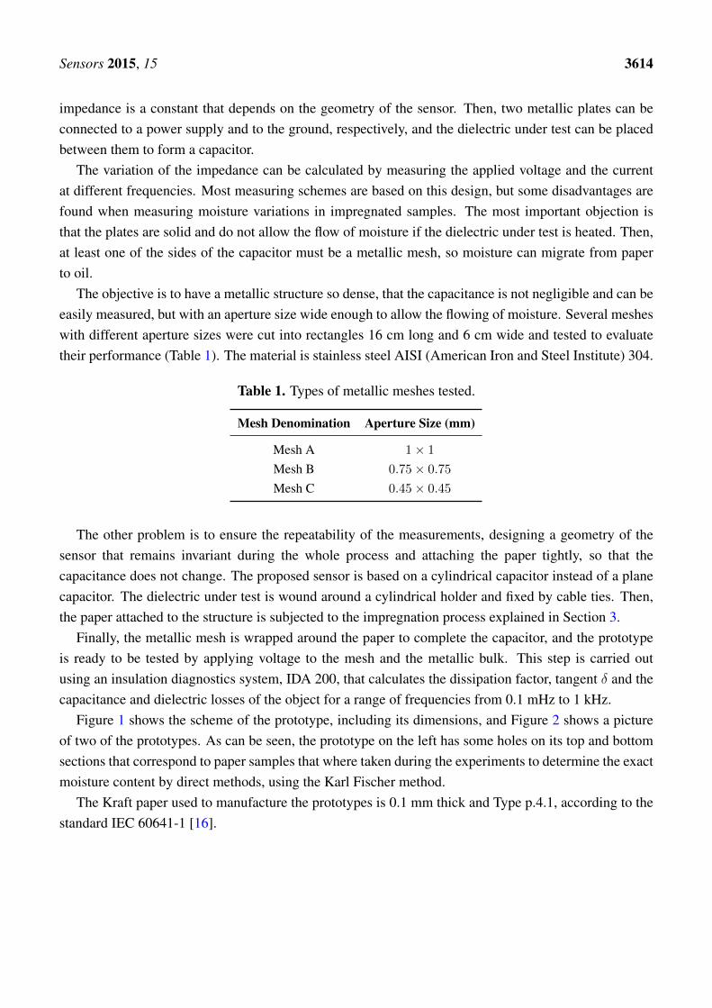
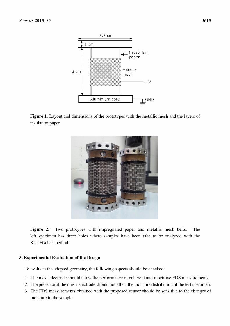
Figure 1 shows the scheme of the prototype, including its dimensions, and Figure 2 shows a pictureof two of the prototypes. As can be seen, the prototype on the left has some holes on its top and bottomsections that correspond to paper samples that where taken during the experiments to determine the exactmoisture content by direct methods, using the Karl Fischer method.
The Kraft paper used to manufacture the prototypes is 0.1 mm thick and Type p.4.1, according to thestandard IEC 60641-1 [16].
Sensors 2015, 15 3615
Figure 1. Layout and dimensions of the prototypes with the metallic mesh and the layers ofinsulation paper.
Figure 2. Two prototypes with impregnated paper and metallic mesh belts. Theleft specimen has three holes where samples have been take to be analyzed with theKarl Fischer method.
3. Experimental Evaluation of the Design
To evaluate the adopted geometry, the following aspects should be checked:
1. The mesh electrode should allow the performance of coherent and repetitive FDS measurements.2. The presence of the mesh-electrode should not affect the moisture distribution of the test specimen.3. The FDS measurements obtained with the proposed sensor should be sensitive to the changes of
moisture in the sample.
Sensors 2015, 15 3616
3.1. Effect of Using a Mesh-Electrode and Selection of the Aperture Size
As explained before, tests were done using meshes with different aperture sizes (Table 1) to evaluatewhich of them were suitable to obtain reliable measurements.
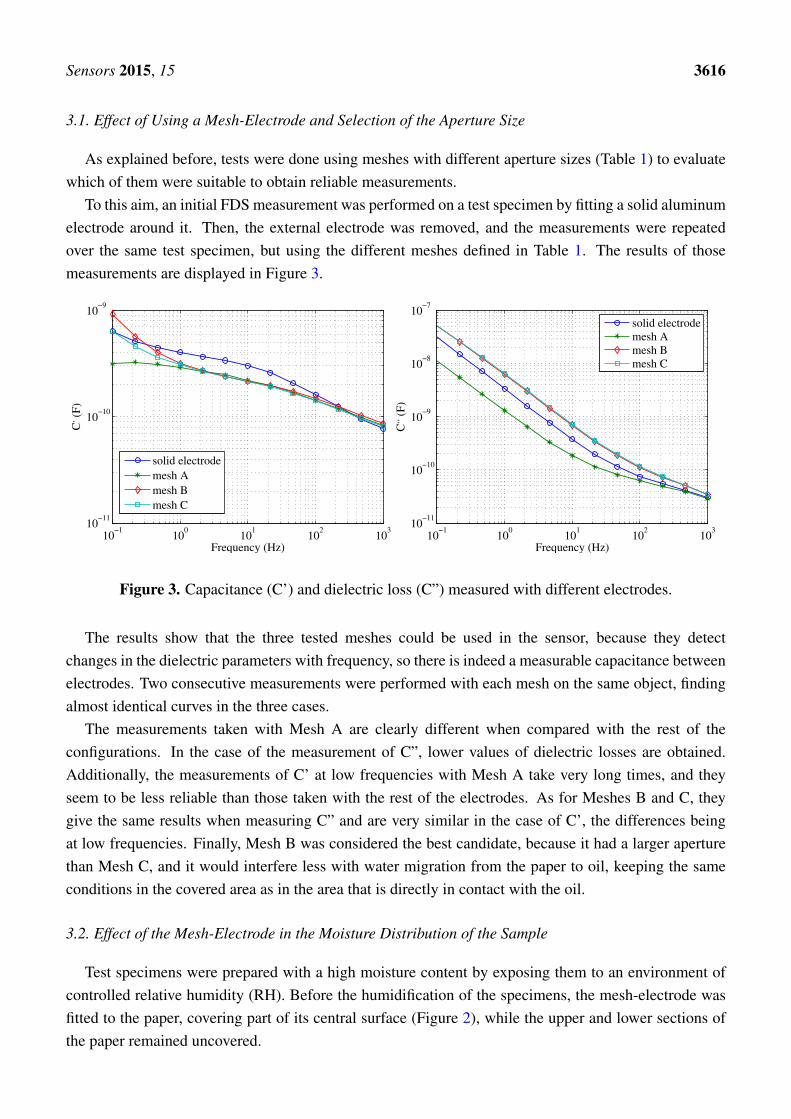
To this aim, an initial FDS measurement was performed on a test specimen by fitting a solid aluminumelectrode around it. Then, the external electrode was removed, and the measurements were repeatedover the same test specimen, but using the different meshes defined in Table 1. The results of thosemeasurements are displayed in Figure 3.
10−1
100
101
102
103
10−11
10−10
10−9
Frequency (Hz)
C, (
F)
solid electrode
mesh A
mesh B
mesh C
10−1
100
101
102
103
10−11
10−10
10−9
10−8
10−7
Frequency (Hz)
C,, (
F)
solid electrode
mesh A
mesh B
mesh C
Figure 3. Capacitance (C’) and dielectric loss (C”) measured with different electrodes.
The results show that the three tested meshes could be used in the sensor, because they detectchanges in the dielectric parameters with frequency, so there is indeed a measurable capacitance betweenelectrodes. Two consecutive measurements were performed with each mesh on the same object, findingalmost identical curves in the three cases.
The measurements taken with Mesh A are clearly different when compared with the rest of theconfigurations. In the case of the measurement of C”, lower values of dielectric losses are obtained.Additionally, the measurements of C’ at low frequencies with Mesh A take very long times, and theyseem to be less reliable than those taken with the rest of the electrodes. As for Meshes B and C, theygive the same results when measuring C” and are very similar in the case of C’, the differences beingat low frequencies. Finally, Mesh B was considered the best candidate, because it had a larger aperturethan Mesh C, and it would interfere less with water migration from the paper to oil, keeping the sameconditions in the covered area as in the area that is directly in contact with the oil.
3.2. Effect of the Mesh-Electrode in the Moisture Distribution of the Sample
Test specimens were prepared with a high moisture content by exposing them to an environment ofcontrolled relative humidity (RH). Before the humidification of the specimens, the mesh-electrode wasfitted to the paper, covering part of its central surface (Figure 2), while the upper and lower sections ofthe paper remained uncovered.
Sensors 2015, 15 3617
After the humidification process, some paper samples were taken at different heights of the testspecimen and analyzed with the Karl Fischer method to determine their moisture content [17].
The moisture distribution in height can be seen in Table 2. Concretely, four different samples weretaken at different heights in a test specimen prepared with a moisture content of about 3%. Two of thesesamples were in the area covered by the mesh and the other two in the uncovered area. Considering thatthe Karl Fischer method has a uncertainty of about 0.3% in the determination of the moisture content ofpaper [17], the differences found between the different samples can be considered negligible.
Table 2. Distribution of moisture in a test specimen along its height.
Sample UbicationMoisture Content (%)
Outside the Mesh Inside the Mesh
Top sample 3.4 3.1Bottom sample 3.5 3.3
Measurements were also made taking samples at three different depths of the specimen inside andoutside the mesh: a sample of external insulation (i.e., in direct contact with air), another at an averagedepth and one of the paper in contact with the aluminum core. As can be seen in Table 3, the moisturedistribution can be also considered homogeneous, and no influence of the mesh can be discerned.
Table 3. Moisture content at different depths of the test specimen.
Sample DeepnessMoisture Content (%)
Outside the Mesh Inside the Mesh
Inner sample 3.1 3.0Central sample 2.9 3.0Outer sample 2.9 3.0
From the previous analysis, it can be concluded that the presence of the chosen mesh does not affectthe movement of water in the insulation. This conclusion seems logical given that the size of the watermolecule is in the range of Å, while the size of the mesh is 0.75 mm.
3.3. Sensitivity of the Sensor
The sensitivity of the sensor to the variation of the moisture of the paper was also determined. To this aim,
measurements were performed on test specimens with different moisture contents. Four specimenswere prepared with moisture contents of 1.8%, 3.6%, 4% and 5.3% with the structure shown in Figure 2using a drying oven and different saline solutions, according to the standard ASTM E104-02 [18].The moisture concentration of the specimens was determined with Karl Fischer titration after the experiments.
The samples were introduced into a Teflon container filled with new and dry mineral oil, as wouldbe done in a real transformer. FDS measurements were carried out using the scheme shown in Figure 4,the applied voltage being 10 V for all cases. The process lasts in the range of tens of minutes, which
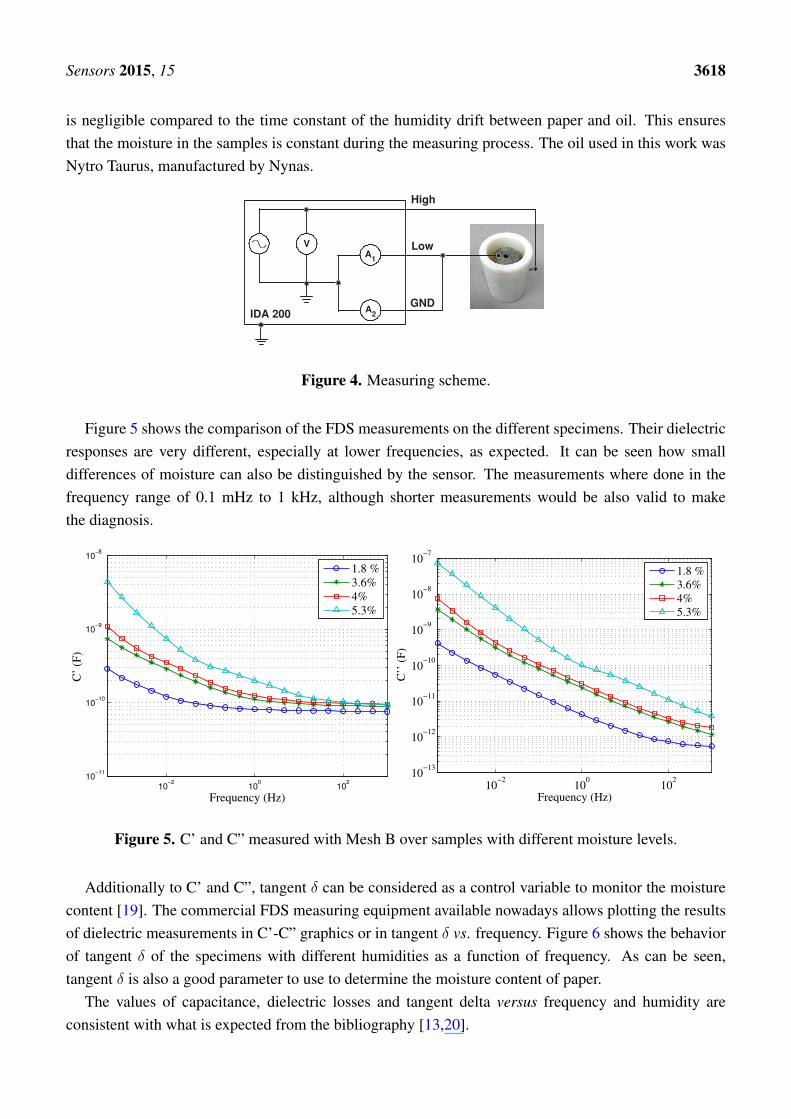
Sensors 2015, 15 3618
is negligible compared to the time constant of the humidity drift between paper and oil. This ensuresthat the moisture in the samples is constant during the measuring process. The oil used in this work wasNytro Taurus, manufactured by Nynas.
V A
1
A 2 IDA 200
High
Low
GND
Figure 4. Measuring scheme.
Figure 5 shows the comparison of the FDS measurements on the different specimens. Their dielectricresponses are very different, especially at lower frequencies, as expected. It can be seen how smalldifferences of moisture can also be distinguished by the sensor. The measurements where done in thefrequency range of 0.1 mHz to 1 kHz, although shorter measurements would be also valid to makethe diagnosis.
10−2
100
102
10−11
10−10
10−9
10−8
C’
(F)
Frequency (Hz)
1.8 %
3.6%
4%
5.3%
10−2
100
102
10−13
10−12
10−11
10−10
10−9
10−8
10−7
Frequency (Hz)
C’’
(F
)
1.8 %
3.6%
4%
5.3%
Figure 5. C’ and C” measured with Mesh B over samples with different moisture levels.
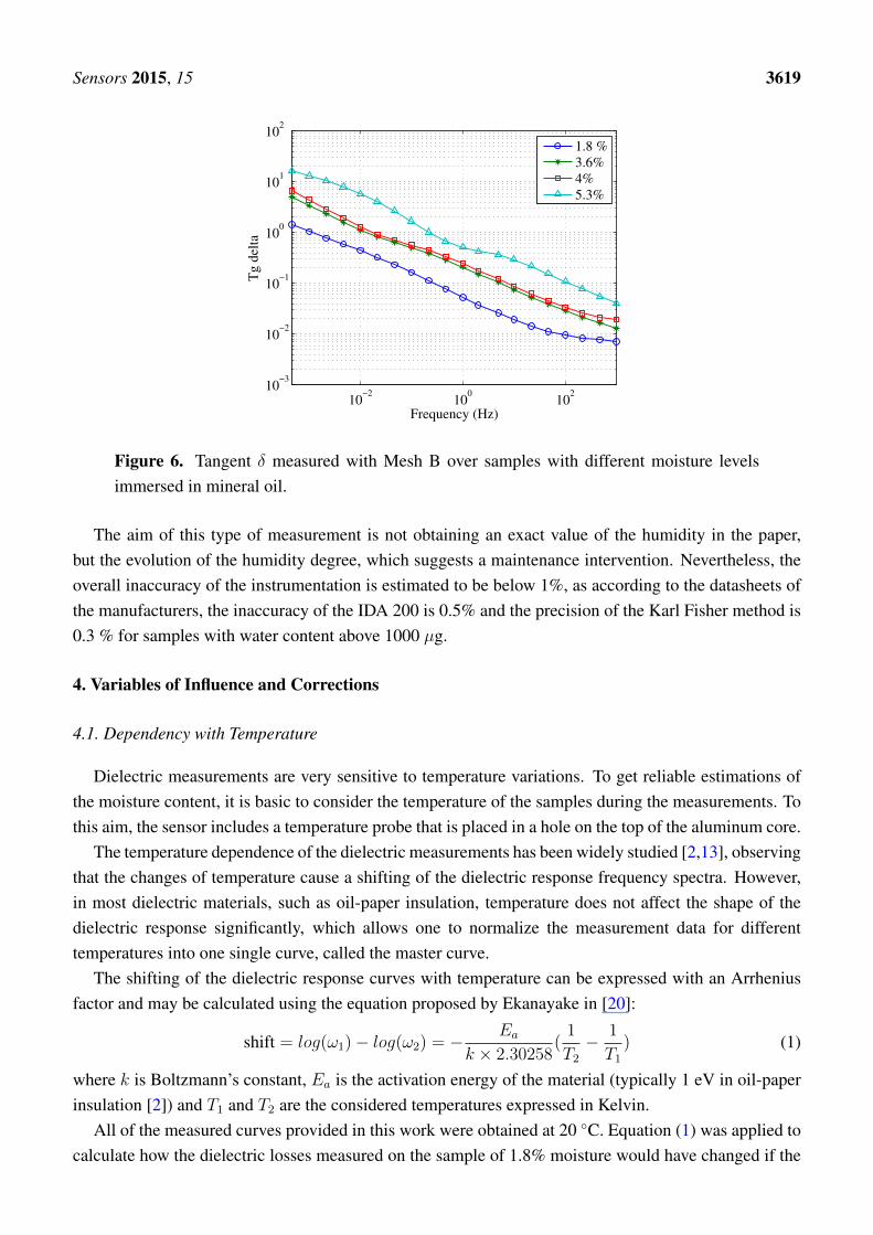
Additionally to C’ and C”, tangent δ can be considered as a control variable to monitor the moisturecontent [19]. The commercial FDS measuring equipment available nowadays allows plotting the resultsof dielectric measurements in C’-C” graphics or in tangent δ vs. frequency. Figure 6 shows the behaviorof tangent δ of the specimens with different humidities as a function of frequency. As can be seen,tangent δ is also a good parameter to use to determine the moisture content of paper.
The values of capacitance, dielectric losses and tangent delta versus frequency and humidity areconsistent with what is expected from the bibliography [13,20].
Sensors 2015, 15 3619
10−2
100
102
10−3
10−2
10−1
100
101
102
Frequency (Hz)
Tg d
elta
1.8 %
3.6%
4%
5.3%
Figure 6. Tangent δ measured with Mesh B over samples with different moisture levelsimmersed in mineral oil.
The aim of this type of measurement is not obtaining an exact value of the humidity in the paper,but the evolution of the humidity degree, which suggests a maintenance intervention. Nevertheless, theoverall inaccuracy of the instrumentation is estimated to be below 1%, as according to the datasheets ofthe manufacturers, the inaccuracy of the IDA 200 is 0.5% and the precision of the Karl Fisher method is0.3 % for samples with water content above 1000 µg.
4. Variables of Influence and Corrections
4.1. Dependency with Temperature
Dielectric measurements are very sensitive to temperature variations. To get reliable estimations ofthe moisture content, it is basic to consider the temperature of the samples during the measurements. Tothis aim, the sensor includes a temperature probe that is placed in a hole on the top of the aluminum core.
The temperature dependence of the dielectric measurements has been widely studied [2,13], observingthat the changes of temperature cause a shifting of the dielectric response frequency spectra. However,in most dielectric materials, such as oil-paper insulation, temperature does not affect the shape of thedielectric response significantly, which allows one to normalize the measurement data for differenttemperatures into one single curve, called the master curve.
The shifting of the dielectric response curves with temperature can be expressed with an Arrheniusfactor and may be calculated using the equation proposed by Ekanayake in [20]:
shift = log(ω1)− log(ω2) = − Ea
k × 2.30258(1
T2− 1
T1) (1)
where k is Boltzmann’s constant, Ea is the activation energy of the material (typically 1 eV in oil-paperinsulation [2]) and T1 and T2 are the considered temperatures expressed in Kelvin.
All of the measured curves provided in this work were obtained at 20 ◦C. Equation (1) was applied tocalculate how the dielectric losses measured on the sample of 1.8% moisture would have changed if the

Sensors 2015, 15 3620
measurements had been taken at temperatures of 50 ◦C and 80 ◦C (Figure 7). The same expression mightbe used to calculate the shifting of other variables, such as capacitance and tangent δ with temperature.
10−4
10−2
100
102
104
106
10−13
10−12
10−11
10−10
10−9
Frequency (Hz)
C’’
(F
)
20 ºC
50 ºC
80 ºC
shift1
shift 2
Figure 7. Dielectric losses of the sample with moisture 1.8% measured at 20 ◦C andcalculated for temperatures 50 ◦C and 80 ◦C (Shift 1 = −1.5976, Shift 2 = −2.9236).
4.2. Influence of the Relative Humidity of the Environment
The relative humidity (RH) of the environment does not have a significant influence in themeasurements of the sensor. The sensor is proposed to be used immersed in oil, which is a veryhydrophobic material. Even in humid environments, the contamination of the paper by water takenfrom oil would be very little. Additionally, the time constants involved in the adsorption of moisture intothe paper at room temperature are in the order of months [2], while the measurements with the sensortake about one hour.
The relative humidity of the air during the measurements shown in this work was monitored andhad a value within 40%–45%. Moreover, when not used, all samples were kept inside containers withsaline solutions that maintain the humidity constant for long periods of time after humidification. Thecontainers, in turn, were stored in a humidity-controlled environment area in the laboratory.
4.3. Influence of the Condition of the Oil
When FDS measurements are done in a real transformer, the insulation between the high voltage andlow voltage windings, usually called the CHL, measurement, or the insulation between one windingand the ground, usually called CHor CLmeasurements, might be characterized. In all cases, a certainvolume of oil is located between the plates of the capacitor that is being measured. The interpretation ofthe FDS measurements used to be based on the representation of the insulation as an XY model, whichshould include information related to the condition of the oil and the proportions of oil and paper presentbetween the plates of the capacitor [13].
Sensors 2015, 15 3621
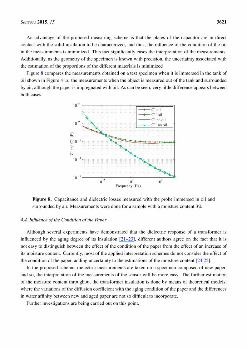
An advantage of the proposed measuring scheme is that the plates of the capacitor are in directcontact with the solid insulation to be characterized, and thus, the influence of the condition of the oilin the measurements is minimized. This fact significantly eases the interpretation of the measurements.Additionally, as the geometry of the specimen is known with precision, the uncertainty associated withthe estimation of the proportions of the different materials is minimized
Figure 8 compares the measurements obtained on a test specimen when it is immersed in the tank ofoil shown in Figure 4 vs. the measurements when the object is measured out of the tank and surroundedby air, although the paper is impregnated with oil. As can be seen, very little difference appears betweenboth cases.
10−2
100
102
10−12
10−11
10−10
10−9
10−8
C’
and C
’’ (
F)
Frequency (Hz)
C’ oil
C’’ oil
C’ no oil
C’’ no oil
Figure 8. Capacitance and dielectric losses measured with the probe immersed in oil andsurrounded by air. Measurements were done for a sample with a moisture content 3%.
4.4. Influence of the Condition of the Paper
Although several experiments have demonstrated that the dielectric response of a transformer isinfluenced by the aging degree of its insulation [21–23], different authors agree on the fact that it isnot easy to distinguish between the effect of the condition of the paper from the effect of an increase ofits moisture content. Currently, most of the applied interpretation schemes do not consider the effect ofthe condition of the paper, adding uncertainty to the estimations of the moisture content [24,25].
In the proposed scheme, dielectric measurements are taken on a specimen composed of new paper,and so, the interpretation of the measurements of the sensor will be more easy. The further estimationof the moisture content throughout the transformer insulation is done by means of theoretical models,where the variations of the diffusion coefficient with the aging condition of the paper and the differencesin water affinity between new and aged paper are not so difficult to incorporate.
Further investigations are being carried out on this point.
Sensors 2015, 15 3622
5. Conclusions
Methods based on the characterization of the dielectric response have been used for years to estimatethe moisture content in transformer solid insulation in field conditions. Nowadays, different commercialequipment is available to make such measurements based on the time domain or the frequency domainanalyses. At present, all of the dielectric response measuring schemes require the transformer to beout of service.
In this paper, a sensor is proposed to determine the moisture content of solid insulation in realtransformers while the equipment is in service. The sensor is based on the characterization of thedielectric response of a Kraft paper coil that would be fit inside the transformer tank and subjectedto the same conditions as the transformer solid insulation.
One of the electrodes has been substituted by a metallic mesh, so that it does not affect the moisturemigration processes between paper and oil that continuously take place during transformer operation.
The proposed scheme has been validated with an in-depth study that evaluates the design and themeasuring principle of the sensor. Firstly, the selection of the mesh electrode has been justified andtested. Measurements were carried out using meshes with different aperture sizes and also using asolid electrode. Then, the effect of the selected mesh in the moisture distribution of the coil wasevaluated using the Karl Fischer method. To this aim, a test specimen was subjected to a humidificationprocess with the mesh on, and the resulting moisture content of the areas covered with the mesh and theuncovered ones were compared in longitudinal and radial directions.
The sensitivity of the sensor was proven on test specimens prepared with different moisture contentsand using the FDS commercial equipment, IDA 200, to determine the dielectric response in the frequencydomain, with the samples immersed in mineral oil. The sensor demonstrated good sensitivity when thesetests were done, allowing us to assume that it will be able to distinguish moisture contents within 1%an 5% with enough accuracy. The values of capacitance versus frequency and humidity were consistentwith the values reported in the bibliography.
The proposed sensor could be a good complement to the off-line dielectric response measurements,as it would allow one to have information between consecutive discharges. Moreover, the geometryand properties of the materials that compose the sensor are perfectly characterized, which eases theinterpretation of the measurements.
The sensor proposed in this work is a prototype. In the future, its dimensions and constructivematerials will be revised to ease its integration into a real on-service transformer. Additional work isalso being done to adjust the dynamic models that will complement the information given by the sensor,allowing one to calculate the moisture distribution throughout the transformer winding.
Acknowledgments
This work has been supported by the Spanish Government under Contract DPI2012-35819.
Author Contributions
DG, BG and GR designed research; BG, DG and GR performed research and analyzed the data; BG,GR and DG wrote the paper. All authors read and approved the final manuscript.

Sensors 2015, 15 3623
Conflicts of Interest
The authors declare no conflict of interest.
References
1. Bartley, W. Analysis of Transformer Failures; In Proceedings of the 36th Annual Conference of theInternational Association of Engineering Insurers, Stockholm, Sweden, September 2003.
2. Working group A2.30. Moisture Equilibrium and Moisture Migration within TransformerInsulation Systems. Technical Brochure 349; Cigré: Paris, France, 2008.
3. Gielniak, J; Graczkowski, A.; Moranda, H.; Przybylek, P.; Walczak, K.; Nadolny, Z.;Moscicka-Grzesiak, H.; Feser, K.; Gubanski, S.M. Moisture in cellulose insulation of powertransformers-statistics. IEEE Trans. Dielectr. Electr. Insul. 2013, 10, 982–987.
4. Bhalla, D; Bansal, R.K.; Gupta, H.O; Hari, O.M. Preventing Power Transformer Failures throughElectrical Incipient Fault Analysis. Int. J. Perform. Eng. 2013, 9, 23–31.
5. Oommen, T. V. Moisture equilibrium in paper-oil insulation systems. In Proceedings ofthe Electrical and Electronics Insulation Conference, Chicago, IL, USA, 3–6 October 1983;pp. 162–166.
6. Griffin, P. J. Water in Transformers-So What! In Proceedings of the National Grid ConditionMonitoring Conference, Surrey, UK, 8–9 May 1996.
7. Du, Y.; Zahn, M.; Lesieutre, B.C. Moisture equilibrium in transformer paper-oil systems.IEEE Electr. Insul. Mag. 1999, 15, 11–20.
8. Guide for Acceptance and Maintenance of Insulating Oil in Equipment, IEEE Std. C57.106-2006;Institute of Electrical and Electronics Engineers: Piscataway, NJ, USA, 2006; pp.1–36.
9. Hribernik, W.; Pascoli, G.; Frohlich, K. An advanced model-based diagnosis system for onlinedetection of the moisture content of power transformer insulation. In Proceedings of the ConferenceRecord of the 2008 IEEE International Symposium on Electrical Insulation, Vancuveor, BC,Canada, 9–12 June 2008; pp. 187–191.
10. Garcia, B.; Burgos; J. C.; Alonso, A.M. ; Sanz, J. A moisture-in-oil model for power transformermonitoring—Part I: Theoretical foundation. IEEE Trans. Power Deliv. 2005, 20, 1417–1422.
11. Martin, D.; Perkasa, C.; Lelekakis, N. Measuring Paper Water Content of Transformers: A NewApproach Using Cellulose Isotherms in Nonequilibrium Conditions. IEEE Trans. Power Deliv.2013, 28, 1433–1439.
12. Koch, M.; Tenbohlen, S.; Stirl, T. Diagnostic Application of Moisture Equilibrium for PowerTransformers. IEEE Trans. Power Deliv. 2010, 25, 2574–2581.
13. Cigre Task Force D1.01.09. Dielectric Response Methods for Diagnostics of Power Transformers;Technical Brochure 254; Cigré: Paris, France, 2004.
14. Villarroel, R.; Garcia, B.; Burgos, J.C.; Garcia, D.F. Experimental study on moisture dynamics intransformers insulated with natural-esters. In Proceedings of the IEEE International Conference onSolid Dielectrics, Bologna, Italy, 30 June–4 July 2013; pp. 545–548.
15. Li, J.; Zhang, Z.; Grzybowski, S.; Liu, Y. Characteristics of moisture diffusion in vegetableoil-paper insulation. IEEE Trans. Dielectr. Electr. Insul. 2012, 19, 1650–1656.
Sensors 2015, 15 3624
16. IEC. Specification for Pressboard and Presspaper for Electrical Purposes—Part 1: Definitions andGeneral Requirements; International Electrotechnical Comission: Geneva, Switzerland, 2007.
17. IEC. Insulating Liquids. Oil-Impregnated Paper and Pressboard. Determination of Water byAutomatic Coulometric Karl Fishcher Titration; International Electrotechnical Comission: Geneva,Switzerland, 1997.
18. Standard Practice for Maintaining Constant Relative Humidity by Means of Aqueous Solutions,ASTM E104-02; ASTM International: West Conshohocken, PA, USA, 2012.
19. Kelly, J; Myers, S.; Stebbins, R. Transformer Maintenance Guide; Transformer MaintenanceInstitute: Tallmadge, OH, USA, 2004.
20. Ekanayake, C. Diagnosis of Moisture in Transformer Insulation—Application of FrequencyDomain Spectroscopy. Ph.D. Thesis, Chalmers University of Technology, Goteborg, Sweden,September 2006.
21. Wang, S.; Wei,J.; Yang, S.; Dong, M.; Zhang, G. Temperature and thermal aging effects on theFrequency Domain Spectroscopy measurement of oil-paper insulation. In Proceedings of the 9thInternational Conference on Properties and Applications of Dielectric Materials, Harbin, China,19–23 July 2009; pp. 329–332.
22. Wang, S.Q.; Zhang, G.J.; Wei, J.L.; Yang, S.; Dong, M.; Huang, X.B. Investigation on dielectricresponse characteristics of thermally aged insulating pressboard in vacuum and oil-impregnatedambient. IEEE Trans. Dielectr. Electr. Insul. 2010, 17, 1853–1862.
23. Aravinda, G.A.; Attaragama, C.; Palawatte, I.T.; Fernando, M.A.; Jayantha, G.A.; Kumara, J.R.Condition monitoring of current transformers using frequency domain dielectric spectroscopy. InProceedings of the 8th International Conference on Industrial and Information Systems, Kandy,Sri Lanka, 17–20 December 2013; pp. 168–173.
24. Baral, A.; Chakravorti, S. Prediction of moisture present in cellulosic part of power transformerinsulation using transfer function of modified debye mode. IEEE Trans. Dielectr. Electr. Insul.2014, 21, 1368–1375.
25. Betie, A.; Meghnefi, F.; Fofana, I; Yeo, Z. On the impacts of ageing and moisture on dielectricresponse of oil impregnated paper insulation systems. In Proceedings of the Conference onElectrical Insulation and Dielectric Phenomena (CEIDP), Montreal, QC, Canada, 14–17 October2012; pp. 219–222.
c© 2015 by the authors; licensee MDPI, Basel, Switzerland. This article is an open access articledistributed under the terms and conditions of the Creative Commons Attribution license(http://creativecommons.org/licenses/by/4.0/).
Related Documents