DEVELOPMENT OF A HYDROSTATIC TRANSMISSION WITH INTEGRATED SUPPLY FOR WORKING HYDRAULICS Jihao Guo*, Ludger Frerichs Institute of Mobile Machines and Commercial Vehicles, Technische Universität Braunschweig, Langer Kamp 19a, 38106 Braunschweig * Corresponding author: Tel.: +49 531 3917196; E-mail address: [email protected] ABSTRACT The paper presents a study of a highly integrated hydraulic powertrain for mobile working machines. The highlight of this new concept is the replacement of separated drive and working pumps in conventional systems with only one displacement pump. After a comparison of different system architectures, the appropriate operating and control strategies for the chosen topology were applied and optimized. With the help of simulations in AMESim, a proof of the function of the hydraulic circuit and the controlling has been established. In addition, the energy saving potential of the integrated hydraulic system is also considered, by comparing the energy consumption of the new and the conventional powertrain in different duty cycles. Keywords: Mobile Hydraulics, Integrated System, Energy Efficiency 1. GENERAL INSTRUCTIONS The reduction of fuel consumption and emissions from construction equipment is required - from a global perspective - due to the lack of fossil resources and the problems of global warming. On the other hand, the industry is making effort to build mobile working machines with lighter and more compact constructions. For the achievement of above-mentioned goals, a concept of an integrated hydraulic drivetrain has been developed. The widely used powertrain in construction machines mainly consists of two separate subsystems - a closed circuit for traction drive and an open circuit for working functions, which are connected by a shaft between the drive and working pump [1]. A power exchange between them is only possible with significant energy losses, because of the double conversion between hydraulic and mechanical energies. Figure 1: Schematic representation of the project idea The aim of this research project is to develop a hydrostatic transmission with an integrated supply of working hydraulics for mobile machines. This means that both the traction drive and the hydraulics for working functions are supplied only by one hydraulic pump (as shown in Figure 1). Besides the benefit of component saving, a flexible flow rate and power distribution without additional hydraulic components is possible. The peak flow rate and power for driving or working functions are not restricted by the dimension of the corresponding pump as well. Furthermore, the regenerated energy from braking actions could be used directly e.g. in a wheel loader for raising the bucket or for steering. In this paper, integrated systems with different kinds of basic circuits (closed or open) are compared and evaluated. Appropriate scales of components or sub-systems have been chosen for the selected topology. The hydraulic circuit and the control strategy of the hydraulic pump and motor are modeled in AMESim with rational simplification and parameterized with parameters given by the manufacturer. The simulations demonstrate the performance and the energy saving potential of the new hydraulic powertrain by different applications. After analyzing the dynamic properties of the system shown in the %& , & ( $

Welcome message from author
This document is posted to help you gain knowledge. Please leave a comment to let me know what you think about it! Share it to your friends and learn new things together.
Transcript
DEVELOPMENT OF A HYDROSTATIC TRANSMISSION WITH INTEGRATED SUPPLY FOR WORKING HYDRAULICS
Jihao Guo*, Ludger Frerichs
Institute of Mobile Machines and Commercial Vehicles, Technische Universität Braunschweig, Langer Kamp 19a,
38106 Braunschweig
* Corresponding author: Tel.: +49 531 3917196; E-mail address: [email protected]
ABSTRACT
The paper presents a study of a highly integrated hydraulic powertrain for mobile working machines.
The highlight of this new concept is the replacement of separated drive and working pumps in
conventional systems with only one displacement pump. After a comparison of different system
architectures, the appropriate operating and control strategies for the chosen topology were applied and
optimized. With the help of simulations in AMESim, a proof of the function of the hydraulic circuit
and the controlling has been established. In addition, the energy saving potential of the integrated
hydraulic system is also considered, by comparing the energy consumption of the new and the
conventional powertrain in different duty cycles.
Keywords: Mobile Hydraulics, Integrated System, Energy Efficiency
1. GENERAL INSTRUCTIONS
The reduction of fuel consumption and emissions
from construction equipment is required - from a
global perspective - due to the lack of fossil
resources and the problems of global warming.
On the other hand, the industry is making effort
to build mobile working machines with lighter
and more compact constructions. For the
achievement of above-mentioned goals, a
concept of an integrated hydraulic drivetrain has
been developed.
The widely used powertrain in construction
machines mainly consists of two separate
subsystems - a closed circuit for traction drive
and an open circuit for working functions, which
are connected by a shaft between the drive and
working pump [1]. A power exchange between
them is only possible with significant energy
losses, because of the double conversion between
hydraulic and mechanical energies.
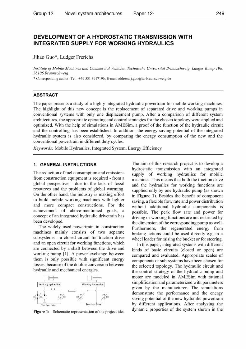
Figure 1: Schematic representation of the project idea
The aim of this research project is to develop a
hydrostatic transmission with an integrated
supply of working hydraulics for mobile
machines. This means that both the traction drive
and the hydraulics for working functions are
supplied only by one hydraulic pump (as shown
in Figure 1). Besides the benefit of component
saving, a flexible flow rate and power distribution
without additional hydraulic components is
possible. The peak flow rate and power for
driving or working functions are not restricted by
the dimension of the corresponding pump as well.
Furthermore, the regenerated energy from
braking actions could be used directly e.g. in a
wheel loader for raising the bucket or for steering.
In this paper, integrated systems with different
kinds of basic circuits (closed or open) are
compared and evaluated. Appropriate scales of
components or sub-systems have been chosen for
the selected topology. The hydraulic circuit and
the control strategy of the hydraulic pump and
motor are modeled in AMESim with rational
simplification and parameterized with parameters
given by the manufacturer. The simulations
demonstrate the performance and the energy
saving potential of the new hydraulic powertrain
by different applications. After analyzing the
dynamic properties of the system shown in the
simulation results, optimization potentials and
possibilities for simplification are discussed.
2. DESIGN OF SYSTEM TOPOLOGY
The drive and working hydraulic circuit of the
new drivetrain must be directly connected by
hydraulic lines, as the whole system is supplied
by only one variable displacement pump.
Therefore, the architecture of the circuits should
be adapted, thus the two subsystems could be
operated independently.
2.1. Topology of the working hydraulic system
In the partial load range, a Closed Center Load
Sensing System (CC-LS) has a higher efficiency
comparing with an Open Center Load Sensing
System (OC-LS) due to the adjustment of pump
flow rate to the demands of the cylinders [2].
Therefore, the efficiency of the working
hydraulics in conventional drivetrain (OC-LS)
could be significantly improved, if the supply unit
is replaced by a variable displacement pump (CC-
LS). As a variable displacement pump is
necessary for the traction drive, a working
hydraulic with CC-LS system could be applied in
the integrated drivetrain without additional
components.
2.2. Topology of the traction drive
The hydrostatic transmissions in mobile
applications are generally closed circuits, by
which the driving direction could be changed
with the reversible drive pump [3]. However, the
suction and the discharge sides exchange by
every reverse, which is an unfavourable condition
for the new integrated system. A directional
control valve is necessary between the traction
drive and working hydraulics, otherwise the
direction of the flow in working hydraulics would
be influenced by reverses of the driving direction.
The requirement of the directional valve is
extremely high, as the pressure by switching
could be higher than 400 bar [4], which is normal
in hydrostatic transmissions in mobile working
machines. Another difficulty for an integrated
system with closed circuit is to balance the
difference of flow rate in loop, which is caused
by differential cylinders in the working hydraulic
system.
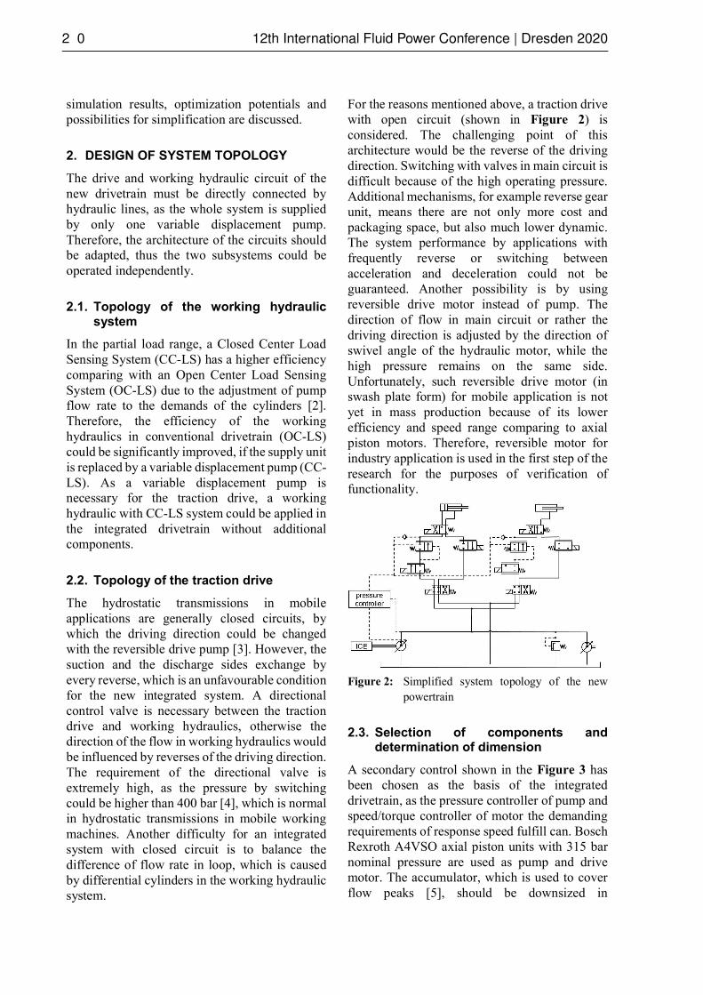
For the reasons mentioned above, a traction drive
with open circuit (shown in Figure 2) is
considered. The challenging point of this
architecture would be the reverse of the driving
direction. Switching with valves in main circuit is
difficult because of the high operating pressure.
Additional mechanisms, for example reverse gear
unit, means there are not only more cost and
packaging space, but also much lower dynamic.
The system performance by applications with
frequently reverse or switching between
acceleration and deceleration could not be
guaranteed. Another possibility is by using
reversible drive motor instead of pump. The
direction of flow in main circuit or rather the
driving direction is adjusted by the direction of
swivel angle of the hydraulic motor, while the
high pressure remains on the same side.
Unfortunately, such reversible drive motor (in
swash plate form) for mobile application is not
yet in mass production because of its lower
efficiency and speed range comparing to axial
piston motors. Therefore, reversible motor for
industry application is used in the first step of the
research for the purposes of verification of
functionality.
Figure 2: Simplified system topology of the new
powertrain
2.3. Selection of components and determination of dimension
A secondary control shown in the Figure 3 has
been chosen as the basis of the integrated
drivetrain, as the pressure controller of pump and
speed/torque controller of motor the demanding
requirements of response speed fulfill can. Bosch
Rexroth A4VSO axial piston units with 315 bar
nominal pressure are used as pump and drive
motor. The accumulator, which is used to cover
flow peaks [5], should be downsized in

consideration of the limited packaging space. The
both axial piston units work with 16 bar pre-
supply pressure, in order to cover a wider speed
range.
Figure 3: Schematic representation of the Bosch
Rexroth secondary control [5]
The dimension of hydraulic components is
determined according to the reference machine, a
wheel loader in power class 40 ~ 50 kW.
Comparing to conventional powertrain, the
hydraulic pump in new system should have a
larger dimension, to enable the supplying of
traction drive and working hydraulics at the same
time. Taking account of the available size of the
series, axial piston units with 71cm3 displacement
have been used as both pump and drive motor.
3. DESIGN OF CONTROL STRATEGY
The design of the control strategy for the new
powertrain is based on the controller in existed
secondary control system. The torque/speed
control for hydraulic motor can also be used in
mobile applications. The drivetrain delivers
torque proportional to accelerator pedal or
according to the difference between actual and
desired speed. On the other side, a pressure
controlled pump is used for achieving the demand
oriented supply in the working hydraulics. In
consideration of the efficiency of both axial
piston units, which is relevant to their opening
degrees, the system should work with variable
pressure. Therefore, the control requires not only
a torque/speed but also a pressure specification as
input variables. In the case of reaching the power
or flow rate limitation, the priority of working
hydraulics will be guaranteed by the timely
swivelling back of the drive motor. To avoid the
undersupply of pump, which causes significant
pressure drop in system, a control strategy for
limiting the motor swivel angel should be
developed.
3.1. Control strategy to determinate system pressure
The system pressure is dependent on both traction
drive and working hydraulics, because of the
direct connection between two subsystems. The
pressure in the working hydraulics (CC-LS
system) is determined by the loads on cylinders.
The output torque of the traction drive is
proportional to the product of displacement
volume of the hydraulic motor and the system
pressure. As the axial piston units have higher
efficiency by larger swivel angles, the pressure in
traction drive should be kept as low as possible.
Furthermore, throttling losses between the two
subsystems could be minimized, if they require a
similar pressure. As the pressure class in traction
drive is generally higher than working hydraulics,
a possible lower target pressure in traction drive
has the benefit of higher efficiency.
Figure 4: Schematic representation of the control
strategy [6]
The control strategy shown in Figure 4 is used
for the definition of the target system pressure
. For safety reasons, the supply for the
working hydraulics (incl. steering system) should
be always be guaranteed. Therefore, the maximal
available flow rate for traction drive
is calculated with Equation 1:
(1)
In the next step, the swivel angle of the drive
motor is adjusted according to the available flow
rate and its current shaft speed, in order to avoid
undersupply of the pump. Equation 2 represents

the maximum allowed displacement of the drive motor.
(2)
If the motor controller is in torque control mode, the target pressure of traction drive can be defined with Equation 3. The target output torque depends on operations (for example acceleration pedal) of the driver. Considering the nominal pressure of the secondary control system, the value will be restricted in the range of 20 ~ 315.
(3)
However, further equations are necessary for establishing mathematical relation between the target rotary speed of the hydraulic motor and the target torque, if the controller is in speed control mode. This part will be explained in detail in chapter 3.2.
On the other hand, the target pressure in the working hydraulics could be defined with Equation 4:
(4)
The target system pressure should follow the higher value:
(5)
If , the unnecessary pressure for working hydraulics would be throttled by pressure compensator valves in the CC-LS system. On the contrary, the displacement of the drive motor must be further reduced, in order to keep the output torque in its target value, as the pressure in traction drive could not be throttled.
3.2. Strategy for speed control of the drive motor
As mentioned above, the relation between target speed and target torque still needs to be established. The output torque of the drive motor actually means the accelerating ability or in other words, the ability, to compensate the difference between the current and the target speed. Therefore, the target pressure of traction drive, which is proportional to target torque, should also demand on the speed difference.
(6)
By selecting function form and setting parameters in Equation 6, the following criterions should be considered: 1. the traction drive must deliver appropriate
torque, in order to compensate the speed difference in acceptable time without overshoot
2. the target pressure should be possibly slow varied, in order to avoid extremely high dynamic demands on secondary control system
With the help of simulation, the following two functions are selected for the determination of target pressure in traction drive:
Linear: (7)
Cubic: (8)
with { } in bar, in min-1
The performance of these two control strategies will be shown and compared in chapter 4.
4. VERIFICATION OF FUNCTIONALITY
The function of the system architecture and control strategies has been proofed by means of computer simulations. In the first step, a model of the hydrostatic drive with the whole control strategy is built in AMESim. Secondly, the performance of the system by various applications is tested with the help of the measuring data from example machine. Finally, the control quality of different strategies is compared and evaluated.
4.1. The Simulation Model of the integrated system
As the research focuses on the power distribution between the traction drive and the working hydraulics, it is not necessary to build the internal structure of working hydraulics in detail. Which means, the flow rates in lift, dump and steering cylinder are considered as a whole. The total flow in working hydraulics is emulated by a flow control valve. The pressure in working hydraulics, which depends on the highest pressure load, is simulated with the help of a pressure relief valve. In the integrated powertrain, the recuperated energy from the working hydraulics is available for traction drive. Therefore, a model for return flow is built and connected with the high pressure side.
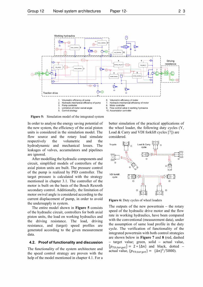
In order to analyse the energy saving potential of the new system, the efficiency of the axial piston units is considered in the simulation model. The flow source and the rotary load simulate respectively the volumetric and the hydrodynamic and mechanical losses. The leakages of valves, accumulators and pipelines are ignored.
After modelling the hydraulic components and circuit, simplified models of controllers of the axial piston units are built. The pressure control of the pump is realized by PID controller. The target pressure is calculated with the strategy mentioned in chapter 3.1. The controller of the motor is built on the basis of the Bosch Rexroth secondary control. Additionally, the limitation of motor swivel angle is considered according to the current displacement of pump, in order to avoid the undersupply in system.
The entire model shown in Figure 5 consists of the hydraulic circuit, controllers for both axial piston units, the load on working hydraulics and the driving resistance. The load, driving resistance, and (target) speed profiles are generated according to the given measurement data.
4.2. Proof of functionality and discussion
The functionality of the system architecture and the speed control strategy are proven with the help of the model mentioned in chapter 4.1. For a
better simulation of the practical applications of the wheel loader, the following duty cycles (Y, Load & Carry and VDI forklift cycles [7]) are considered.
Figure 6: Duty cycles of wheel loaders
The outputs of the new powertrain the rotary speed of the hydraulic drive motor and the flow rate in working hydraulics, have been compared with the conventional (measurement data), under the assumption of same load profile in the duty cycle. The verification of functionality of the integrated powertrain with both control strategies are shown below in Figure 7 and 8 (red, dashed
target value; green, solid actual value, and black, dotted
actual value, ).
Figure 5: Simulation model of the integrated system
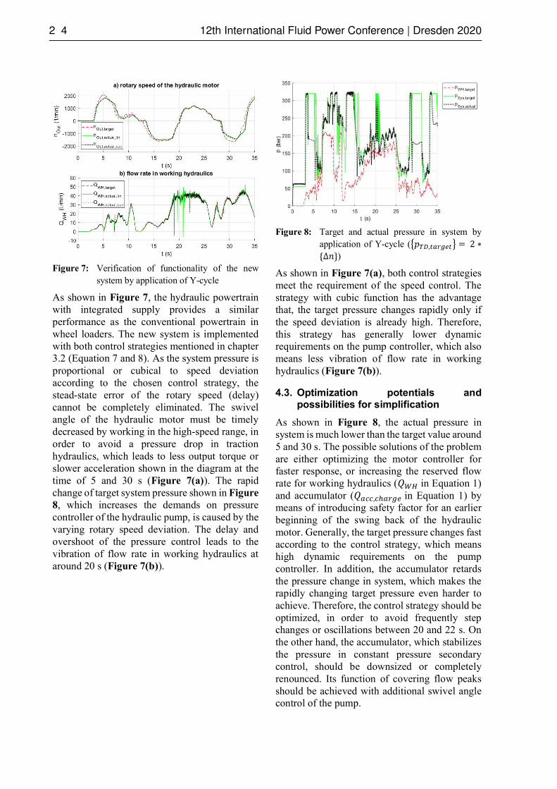
Figure 7: Verification of functionality of the new system by application of Y-cycle
As shown in Figure 7, the hydraulic powertrain with integrated supply provides a similar performance as the conventional powertrain in wheel loaders. The new system is implemented with both control strategies mentioned in chapter 3.2 (Equation 7 and 8). As the system pressure is proportional or cubical to speed deviation according to the chosen control strategy, the stead-state error of the rotary speed (delay) cannot be completely eliminated. The swivel angle of the hydraulic motor must be timely decreased by working in the high-speed range, in order to avoid a pressure drop in traction hydraulics, which leads to less output torque or slower acceleration shown in the diagram at the time of 5 and 30 s (Figure 7(a)). The rapid change of target system pressure shown in Figure
8, which increases the demands on pressure controller of the hydraulic pump, is caused by the varying rotary speed deviation. The delay and overshoot of the pressure control leads to the vibration of flow rate in working hydraulics at around 20 s (Figure 7(b)).
Figure 8: Target and actual pressure in system by application of Y-cycle (
)
As shown in Figure 7(a), both control strategies meet the requirement of the speed control. The strategy with cubic function has the advantage that, the target pressure changes rapidly only if the speed deviation is already high. Therefore, this strategy has generally lower dynamic requirements on the pump controller, which also means less vibration of flow rate in working hydraulics (Figure 7(b)).
4.3. Optimization potentials and possibilities for simplification
As shown in Figure 8, the actual pressure in system is much lower than the target value around 5 and 30 s. The possible solutions of the problem are either optimizing the motor controller for faster response, or increasing the reserved flow rate for working hydraulics ( in Equation 1) and accumulator ( in Equation 1) by means of introducing safety factor for an earlier beginning of the swing back of the hydraulic motor. Generally, the target pressure changes fast according to the control strategy, which means high dynamic requirements on the pump controller. In addition, the accumulator retards the pressure change in system, which makes the rapidly changing target pressure even harder to achieve. Therefore, the control strategy should be optimized, in order to avoid frequently step changes or oscillations between 20 and 22 s. On the other hand, the accumulator, which stabilizes the pressure in constant pressure secondary control, should be downsized or completely renounced. Its function of covering flow peaks should be achieved with additional swivel angle control of the pump.
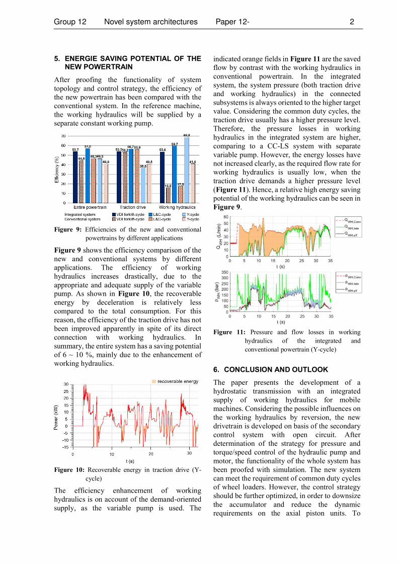
5. ENERGIE SAVING POTENTIAL OF THE NEW POWERTRAIN
After proofing the functionality of system topology and control strategy, the efficiency of the new powertrain has been compared with the conventional system. In the reference machine, the working hydraulics will be supplied by a separate constant working pump.
Figure 9: Efficiencies of the new and conventional powertrains by different applications
Figure 9 shows the efficiency comparison of the new and conventional systems by different applications. The efficiency of working hydraulics increases drastically, due to the appropriate and adequate supply of the variable pump. As shown in Figure 10, the recoverable energy by deceleration is relatively less compared to the total consumption. For this reason, the efficiency of the traction drive has not been improved apparently in spite of its direct connection with working hydraulics. In summary, the entire system has a saving potential of 6 ~ 10 %, mainly due to the enhancement of working hydraulics.
Figure 10: Recoverable energy in traction drive (Y-
cycle)
The efficiency enhancement of working hydraulics is on account of the demand-oriented supply, as the variable pump is used. The
indicated orange fields in Figure 11 are the saved flow by contrast with the working hydraulics in conventional powertrain. In the integrated system, the system pressure (both traction drive and working hydraulics) in the connected subsystems is always oriented to the higher target value. Considering the common duty cycles, the traction drive usually has a higher pressure level. Therefore, the pressure losses in working hydraulics in the integrated system are higher, comparing to a CC-LS system with separate variable pump. However, the energy losses have not increased clearly, as the required flow rate for working hydraulics is usually low, when the traction drive demands a higher pressure level (Figure 11). Hence, a relative high energy saving potential of the working hydraulics can be seen in Figure 9.
Figure 11: Pressure and flow losses in working hydraulics of the integrated and conventional powertrain (Y-cycle)
6. CONCLUSION AND OUTLOOK
The paper presents the development of a hydrostatic transmission with an integrated supply of working hydraulics for mobile machines. Considering the possible influences on the working hydraulics by reversion, the new drivetrain is developed on basis of the secondary control system with open circuit. After determination of the strategy for pressure and torque/speed control of the hydraulic pump and motor, the functionality of the whole system has been proofed with simulation. The new system can meet the requirement of common duty cycles of wheel loaders. However, the control strategy should be further optimized, in order to downsize the accumulator and reduce the dynamic requirements on the axial piston units. To

evaluate the energy saving potential, the efficiency of the new and conventional system is calculated with the help of simulation models. The integrated system provides an efficiency enhancement of 6 ~ 10 %, as the flow in working hydraulics is supplied as required.
In the following step, the functionality of system architecture and control will be validated on the test bench. The operating and control strategy will be adjusted and optimized according to the system dynamics in practice. On the other hand, the possibility of renouncement of accumulators and other methods to simplify the system topology will be examined. Finally, an integrated system with components for mobile applications will be implemented.
7. ACKNOWLEDGEMENTS
The content of this contribution is mainly based
Fahrantrieb mit integrierter Versorgung der -
Vorhaben Nr. 18092 N/1. The authors would like to thank the research association Forschungskuratorium Maschinenbau e. V. FKM, the Forschungsvereinigung Baumaschinen und Baustoffanlagen of the VDMA and the belonging companies for supporting the project.
NOMENCLATURE
CC-LS Closed Center Load Sensing Opening degree Target output torque [Nm] Rotary speed of drive motor [1/min] Target output rotary speed [1/min] Rotary speed of pump [1/min]
OC-LS Open Center Load Sensing Load pressure [bar] Target system pressure [bar] Target pressure of traction drive [bar] Target pressure of working hydraulics [bar]Charging flow rate of the accumulator [L/min] Maximal available flow rate for traction drive [L/min] Maximal pump flow rate [L/min] Flow rate in working hydraulics [L/min] Maximal flow rate in working hydraulics [L/min]
Displacement of motor [ ] Maximal displacement of motor [ ]
Maximal allowed displacement of drive motor [ ] Maximal displacement of pump [ ] Rotary speed difference [1/min] Load Sensing pressure [bar]
REFERENCES
[1] N.N (2010) Shop Manual: KOMATSU VEBM550101, 2010-11. pp: 10-7.
[2] Frerichs L (2018) Ölhydraulik - Schaltungen und Systeme. Vorlesungsskript Institut für mobile Maschinen und Nutzfahrzeuge, TU Braunschweig. pp: 74-76.
[3] Findeisen D (2006) Ölhydraulik: Handbuch für die hydrostatische Leistungsübertragung in der Fluidtechnik. 5., neu bearbeitete Auflage. pp: 18-29.
[4] Roos L, Untch J (2012) Traktorhydraulik. In: Frerichs, L. (Hrsg.): Jahrbuch Agrartechnik 2012, pp: 1-10.
[5] N.N (2012) Data Sheet: Bosch Rexroth RE 92057/12.2012
[6] Guo J, Kossen H.N, Frerichs L (2018) Aufwertung hydraulischer Antriebe am Beispiel Radlader. 10th MHK, Braunschweig.
[7] VDI-Richtlinien 2198 (2012) Typenblätter für Flurförderzeuge.
Related Documents