Development of a creep-damage model for non-isothermal long-term strength analysis of high-temperature components operating in a wide stress range Promotionsschrift zur Erlangung des akademischen Grades Dr.-Ing. vorgelegt dem Zentrum f¨ ur Ingenieurwissenschaften der Martin-Luther-Universit¨ at Halle-Wittenberg von Herrn M.Sc. Yevgen Gorash geb. am 07.11.1981 in Kharkiv (Ukraine) Gutachter: 1. Prof. Dr.-Ing. habil. Dr.h.c. Holm Altenbach, Halle (Saale) 2. Prof. Dr.techn.Wiss. Gennadiy I. Lvov, Kharkiv Halle (Saale), 21. Juli 2008 urn:nbn:de:gbv:3-000014163 [http://nbn-resolving.de/urn/resolver.pl?urn=nbn%3Ade%3Agbv%3A3-000014163]

Welcome message from author
This document is posted to help you gain knowledge. Please leave a comment to let me know what you think about it! Share it to your friends and learn new things together.
Transcript

Development of a creep-damage model fornon-isothermal long-term strength analysis
of high-temperature componentsoperating in a wide stress range
Promotionsschrift
zur Erlangung des akademischen Grades
Dr.-Ing.
vorgelegt dem
Zentrum fur Ingenieurwissenschaftender Martin-Luther-Universitat Halle-Wittenberg
von
Herrn M.Sc. Yevgen Gorash
geb. am 07.11.1981 in Kharkiv (Ukraine)
Gutachter:
1. Prof. Dr.-Ing. habil. Dr.h.c. Holm Altenbach, Halle (Saale)
2. Prof. Dr.techn.Wiss. Gennadiy I. Lvov, Kharkiv
Halle (Saale), 21. Juli 2008
urn:nbn:de:gbv:3-000014163[http://nbn-resolving.de/urn/resolver.pl?urn=nbn%3Ade%3Agbv%3A3-000014163]

III
PREFACE
The given Ph.D. thesis was accomplished as the final result ofmy post-graduate study at thechair “Dynamics and Strength of Machines” (National Technical University “KhPI”, Kharkiv,Ukraine) and the subsequent academic probation at the chair“Technische Mechanik” (Martin-Luther-Universitat Halle-Wittenberg) within the framework of the DAAD scholarship for post-graduate students and young scientists (A/06/09452).
I express my deep gratitude to German Academic Exchange Service (Deutscher AkademischerAustausch Dienst) for the essential financial support during my residence in Germany whileworking under the Ph.D. thesis and all previous visits within the framework of studentsacademic exchange programs. Thanks for the great possibility to establish an efficient scientificcollaboration with German academics, to realize personal academic development and to achievethe formulated scientific objectives including the defenceof Ph.D. thesis.
The given work was created under the scientific supervision and management of ProfessorsHolm Altenbach (MLU Halle-Wittenberg) and Gennadiy I. Lvov(NTU “KhPI”, Kharkiv,Ukraine). I would like to thank them for the educating me as a scientist, invaluable academicexperience in the solution of complex problems, sufficient freedom of choice and decision,strong motivation and generous support during all the time of the Ph.D. thesis preparation.
The profound gratitude to PD Dr.-Ing. Konstantin Naumenko for the everyday kind assistancein academic problems and effective collaboration in scientific sphere. It would be impossibleto complete my Ph.D. thesis without deep theoretical knowledge in the field of CreepMechanics and advanced practical skill in graphical designand organization of scientificactivities, which Dr. Naumenko generously sheared with me.
Moreover, I appreciate sincerely to all co-workers, Ph.D. students and students at the chair“Technische Mechanik” of Martin-Luther-Universitat Halle-Wittenberg for their permanentreadiness to help, constructive interest and discussions,favourable team atmosphere and perfectworking conditions.
My special heartfelt gratitudes to my parents for their understanding and compliant assistancein all my initiatives and to my beloved fiancee Nadiia Maiboroda for the every day essentialencouragement and creative inspiration for the achievement of maximum goals.
Halle (Saale), July 2008
Yevgen Gorash
IV
ABSTRACT
The structural analysis under in-service conditions at various temperatures requires a reliablecreep constitutive model which reflects time-dependent creep deformations and processes ac-companying creep like hardening and damage in a wide stress range. The objective of this workis to develop a comprehensive non-isothermal creep-damagemodel based on transitions of creepand long-term strength behavior in a wide stress range. The important features of the proposedcreep and damage equations are the response functions of theapplied stress which should ex-trapolate the laboratory creep and rupture data usually obtained in tests under increased stressand temperature to the in-service loading conditions relevant for industrial applications. Thestudy deals with four principal topics including the basic assumptions of creep constitutivemodeling, the conventional isotropic and anisotropic creep-damage models, the comprehen-sive non-isothermal creep-damage models for a wide stress range. Finally, the application tostructural analysis of benchmark problems and engineeringcomponents is demonstrated.
Within the framework of the constitutive modeling we discuss different creep-deformationmechanisms depending on stress and temperature level and their unification in the frames ofone creep constitutive model based on micro-structural experimental studies. An overview ofconventional approaches to phenomenological creep modeling with temperature dependence isgiven. It includes creep-damage models based on the Kachanov-Rabotnov-Hayhurst conceptand creep material models with both the initial and the damage induced anisotropy.
The proposed non-isothermal creep-damage model for a wide stress range is based on sev-eral assumptions derived from creep experiments and microstructural observations for variousadvanced heat resistant steels. The constitutive equationaffects the stress range dependent be-havior demonstrating the power-law to linear creep transition with a decreasing stress. To takeinto account the primary creep behavior a strain hardening function is introduced. To charac-terize the creep-rupture behavior the constitutive equation is generalized by introduction of twodamage internal state variables and appropriate evolutionequations. The description of long-term strength behaviour is based on the assumption of ductile to brittle damage transition witha decrease of stress. Two damage parameters represent the different ductile and brittle damageaccumulation. The creep constitutive and damage evolutionequations are extended includingthe temperature dependence using the Arrhenius-type functions. The unified multi-axial formof the creep-damage model for a wide stress range is presented. A new failure criterion includesboth the maximum tensile stress and the von Mises effective stress. The measures of influenceof the both these stress parameters are dependent on the level of stress.
Several isotropic and anisotropic creep-damage models areapplied to the numerical struc-tural analysis using FEM-based CAE-software ABAQUS and ANSYS. These models are incor-porated into the software finite element code by means of a user-defined material subroutines.To verify the subroutines several creep benchmark problemsare developed and solved by spe-cial numerical methods. The examples of long-term strengthanalysis for various industrialcomponents are highlighted to illustrate the effective features and importance of the continuumdamage mechanics approach for the life-time assessments instructural analysis. Finally, anexample of long-term strength analysis for the housing of a quick stop valve usually installedon steam turbines is presented. The results show that the developed approach is capable toreproduce basic features of creep and damage processes in engineering structures.
V
ZUSAMMENFASSUNG
Eine Strukturanalyse unter Betriebsbedingungen bei verschiedenen Temperaturen setzt ein zu-verlassiges Kriechkonstitutivmodell, welches zeitabh¨angige Kriechdeformationen widerspie-gelt und begleitende Prozesse wie Verfestigung und Schadigung uber einen großen Spannungs-bereich erfassen kann, voraus. Das Ziel dieser Arbeit ist die Entwicklung eines umfassenden,nicht-isothermen Kriech- und Schadigungsmodells, das die Ubergange im Verhalten des Krie-chens und der Langzeitfestigkeit beschreibt. Wesentlicher Bestandteil der vorgestellten Kriech-und Schadigungsgleichungen sind die Antwortfunktionen zur aufgebrachten Spannung, welchedie experimentellen Kriech- und Versagensdaten, die gewohnlich unter erhohten Spannungenund Temperaturen ermittelt werden, auf die Betriebsbedingungen extrapolieren sollten. DieseArbeit ist gegliedert in vier Themenbereiche: Grundannahmen der Modellierung, konventio-nelle isotrope und anisotrope Kriech- und Schadigungsmodelle, nicht-isothermes Kriech- undSchadigungsmodell fur große Spannungsbereiche sowie mehrere Beispiele fur die numerischeAbschatzung des Kriechens und der Schadigung bei Benchmarkproblemen und Bauteilen.
Im Rahmen der Modellierung werden verschiedene Mechanismen der Kriechdeformati-on, die vom Spannungs- und Temperaturniveau abhangen sowie deren Beschreibung in einemKriechkonstitutivmodell, dem experimentelle Ergebnissezu Grunde liegen, diskutiert. Es wirdein Uberblick uber konventionelle Ansatze zur phanomenologischen Modellierung des Krie-chens mit Temperaturabhangigkeit gegeben. Das beinhaltet Kriech- und Schadigungsmodelle,die auf den Arbeiten von Kachanov-Rabotnov-Hayhurst beruhen, und Kriechmodelle mit so-wohl einer anfanglichen als auch einer durch Schadigung induzierten Anisotropie.
Dem vorgestellten Kriech- und Schadigungsmodell liegen Annahmen zu Grunde, die aus ex-perimentellen Beobachtungen fur zahlreiche warmfeste Stahle abgeleitet wurden. Das von derKonstitutivgleichung beschriebene Kriechverhalten zeigt einenUbergang vom exponentiellenzum linearen Verhalten mit geringeren Spannungen. Um das Primarkriechen zu berucksichtigenwurde eine Funktion mit Dehnungsverfestigung verwendet. Das Versagen durch Kriechen wirdhinreichend genau beschrieben, wenn in die Konstitutivgleichung zwei Schadigungsparameterund die dazugehorigen Evolutionsgleichungen eingefuhrt sind. Die Beschreibung des Ver-haltens bezuglich der Langzeitfestigkeit basiert auf derAnnahme desUbergangs von dukti-lem zu sprodem Verhalten mit abnehmender Spannung. Die zwei Schadigungsparameter ha-ben einen unterschiedlichen Charakter bei duktiler und sproder Schadigungsakkumulierung.Die Kriechkonstitutiv- und Evolutionsgleichungen sind durch einen Arrheniusansatz erweitertworden, so dass die Temperaturabhangigkeit berucksichtigt werden kann. Die vereinheitlich-te mehraxiale Form des Kriech- und Schadigungsmodells fur große Spannungsbereiche wirdprasentiert. Ein neues Versagenskriterium, das sowohl die maximale Zugspannung als auch dieeffektive von Mises-Spannung beinhaltet, wird eingefuhrt.
Mehrere Kriech- und Schadigungsmodelle wurden fur Analysen von Bauteilen mit FEM-basierte Software wie ABAQUS und ANSYS verwendet. Diese Modelle wurden mithilfe vonbenutzerspezifischen Subroutinen in die Software integriert. Um diese Subroutinen zu verifizie-ren, wurden mehrere Benchmark-Kriechprobleme aufgestellt und numerisch gelost. Beispiels-weise wird eine Simulation zur Abschatzung der Langzeitfestigkeit anhand des Gehauses einesQuick-Stop Ventils einer Dampfturbine prasentiert. Die Ergebnisse belegen, dass der entwickel-te Ansatz in der Lage ist, die Merkmale des Kriechschadigungsprozesses zu erfassen.

VI

CONTENTS
1. Basic Assumptions and Motivation. . . . . . . . . . . . . . . . . . . . . . . . . . . 11.1 Creep Phenomena. . . . . . . . . . . . . . . . . . . . . . . . . . . . . . . . . 11.2 Phenomenological Modeling. . . . . . . . . . . . . . . . . . . . . . . . . . . 31.3 Creep Deformation Mechanisms. . . . . . . . . . . . . . . . . . . . . . . . . 71.4 Creep and Damage Models. . . . . . . . . . . . . . . . . . . . . . . . . . . . 131.5 Scope and Motivation. . . . . . . . . . . . . . . . . . . . . . . . . . . . . . . 16
2. Conventional approach to creep-damage modeling. . . . . . . . . . . . . . . . . . . 192.1 Non-isothermal isotropic creep-damage model. . . . . . . . . . . . . . . . . . 20
2.1.1 Uni-axial stress state. . . . . . . . . . . . . . . . . . . . . . . . . . . 202.1.2 Multi-axial stress state. . . . . . . . . . . . . . . . . . . . . . . . . . 21
2.2 Anisotropic creep-damage models. . . . . . . . . . . . . . . . . . . . . . . . 222.2.1 Model for anisotropic creep in a multi-pass weld metal. . . . . . . . . 222.2.2 Murakami-Ohno creep model with damage induced anisotropy . . . . . 28
3. Non-isothermal creep-damage model for a wide stress range . . . . . . . . . . . . . 313.1 Non-isothermal creep constitutive modeling. . . . . . . . . . . . . . . . . . . 323.2 Stress relaxation problem and primary creep modeling. . . . . . . . . . . . . 37
3.2.1 Stress relaxation problem. . . . . . . . . . . . . . . . . . . . . . . . . 383.2.2 Primary creep strain. . . . . . . . . . . . . . . . . . . . . . . . . . . 45
3.3 Non-isothermal long-term strength and tertiary creep modeling . . . . . . . . . 463.3.1 Stress dependence. . . . . . . . . . . . . . . . . . . . . . . . . . . . 493.3.2 Creep-damage coupling. . . . . . . . . . . . . . . . . . . . . . . . . 513.3.3 Temperature dependence. . . . . . . . . . . . . . . . . . . . . . . . . 56
3.4 Stress-dependent failure criterion. . . . . . . . . . . . . . . . . . . . . . . . . 59
4. Creep estimations in structural analysis. . . . . . . . . . . . . . . . . . . . . . . . . 634.1 Application of FEM to creep-damage analysis. . . . . . . . . . . . . . . . . . 634.2 Numerical benchmarks for creep-damage modeling. . . . . . . . . . . . . . . 66
4.2.1 Purposes and applications of benchmarks. . . . . . . . . . . . . . . . 664.2.2 Simply supported beam. . . . . . . . . . . . . . . . . . . . . . . . . 674.2.3 Pressurized thick cylinder. . . . . . . . . . . . . . . . . . . . . . . . 67
4.3 Anisotropic creep of a pressurized T-piece pipe weldment . . . . . . . . . . . . 704.3.1 Formulation of structural model. . . . . . . . . . . . . . . . . . . . . 704.3.2 Analysis of numerical results. . . . . . . . . . . . . . . . . . . . . . . 70
4.4 Creep-damage analysis of power plant components. . . . . . . . . . . . . . . 74

VIII Contents
4.4.1 Previous experience in FEA. . . . . . . . . . . . . . . . . . . . . . . 744.4.2 Steam turbine quick-stop valve. . . . . . . . . . . . . . . . . . . . . . 76
5. Conclusions and Outlook. . . . . . . . . . . . . . . . . . . . . . . . . . . . . . . . 83
A. Identification procedure of creep material parameters. . . . . . . . . . . . . . . . . 85A.1 Secondary creep stage. . . . . . . . . . . . . . . . . . . . . . . . . . . . . . . 85A.2 Tertiary creep stage. . . . . . . . . . . . . . . . . . . . . . . . . . . . . . . . 86A.3 Primary creep stage. . . . . . . . . . . . . . . . . . . . . . . . . . . . . . . . 87
Bibliography . . . . . . . . . . . . . . . . . . . . . . . . . . . . . . . . . . . . . . . . 106

1. BASIC ASSUMPTIONS AND MOTIVATION
Creep is the progressive time-dependent inelastic deformation under constant load and tem-perature.Relaxationis the time-dependent decrease of stress under the condition of constantdeformation and temperature. For many structural materials, for example steel, both the creepand the relaxation can be observed above a certain critical temperature. The creep processis accompanied by many different slow microstructural rearrangements including dislocationmovement, ageing of microstructure and grain-boundary cavitation.
The above definitions of creep and relaxation [152] are related to the case of uni-axial ho-mogeneous stress states realized in standard material testing. But many responsible engineeringstructures and components are subjected to high temperature environment and complex mechan-ical loadings over a long time of operation. Examples include structural components of powergeneration plants, chemical facilities, heat engines and other high-temperature equipment. Thelife of these structures is usually limited by possible time-dependent creep processes. Undercreep in structuresone usually understands time-dependent changes of strain and stress statestaking place in structural components as a consequence of external loading and temperature.Examples of these changes include progressive deformations, relaxation and redistribution ofstresses, local reduction of material strength, etc. Furthermore, the strain and stress states areinhomogeneous and multi-axial in most cases. The aim of “creep modeling for structural analy-sis” is the development of methods to predict time-dependent changes of stress and strain statesin engineering structures up to the critical stage of creep rupture, see e.g. [34, 152].
Design procedures and residual life assessments for such responsible high-temperaturestructural components as pressure piping systems and vessels, rotors and turbine blades, casingsof valves and turbines, etc. require the accounting for creep and damage processes. Chapter1 isdevoted to the discussion of basic features of materials creep and damage behavior, the overviewof main creep-deformation mechanisms, the highlighting ofmain approaches to phenomenolog-ical creep modeling and the definition of the scope for this contribution.
1.1 Creep Phenomena
In design of engineering structures against creep it is necessary to seek the material and theshape which will carry the design loads, without failure, for the design life at the design tem-perature. The meaning of “failure” depends on the application. Following four main types offailure illustrated in Fig.1.1are distinguished in [24, 25]:
a) Displacement-limited applications, in which precise dimensions or small clearances mustbe maintained (as in discs and blades of turbines).

2 1. Basic Assumptions and Motivation
a) b)
c)
d)
σ
σ
σσ
σ
σσ
ω
pp
p
T
T
T T
Fig. 1.1:Creep is important in four classes of design [25]: a) displacement-limited, b) buckling-limited,c) relaxation-limited, d) failure-limited.
b) Buckling-limited applications subjected to compressive loads, in which creep strain cancause buckling failure (as in high pressure pipelines).
c) Stress-relaxation-limited applications in which an initial tension relaxes with time (as inthe pretensioning of cables or bolts).
d) Rupture-limited applications, in which dimensional tolerance is relatively unimportant,but fracture must be avoided (as in steam turbine quick stop valve).
Design procedures and residual life assessments for such responsible high-temperaturestructural components as pressure piping systems and vessels, rotors and turbine blades, casingsof valves and turbines, etc. require the accounting for creep and damage processes. The aim ofcreep modeling for structural analysis is the development of reliable methods and creep modelsto predict time-dependent changes of stress and strain states in engineering structures up to thecritical stage of creep rupture, see e.g. [34, 152].
Structural analysis under creep conditions requires a reliable constitutive model whichreflects time dependent creep deformations and processes accompanying creep like harden-ing/recovery and damage. To tackle any of these we need constitutive equations which relatethe creep strain rateεcr or time-to-failuret∗ for the material to the stressσ and temperatureT towhich the material is exposed. The phenomenological approach to the development of a creep

1.2. Phenomenological Modeling 3
constitutive model is based on mathematical description ofexperimental creep curves obtainedfrom uniaxial creep tests.
A standard cylindrical tension specimen is heated up to the temperatureT = (0.3− 0.5)Tm
(Tm is the melting temperature of the material) and loaded by a tensile forceF. The value ofthe normal stress in the specimenσ0 should be much less than the yield limit of the materialσy. The instantaneous material response is therefore elastic. The load and the temperature arekept constant during the test and the axial engineering strain ε is plotted versus timet. A typicalcreep curve for a metal is schematically shown in Fig.1.2, the same examples of schematic rep-resentation of creep curve can be found in [24, 25, 145, 152, 179]. The instantaneous responsecan be characterized by the strain valueεel . The time-dependent response is the slow increaseof the strainε with a variable rate. Following Andrade [58], three stages can be considered in atypical creep curve: the first stage (primary or reduced creep), the second stage (secondary orstationary creep) and the third stage (tertiary or accelerated creep). During the primary creepstage the creep rate decreases to a certain value (minimum creep rateεcrmin). The secondarystage is characterized by the approximately constant creeprate. During the tertiary creep stagethe strain rate increases. At the end of the tertiary stage creep rupture of the specimen occurs attime momentt∗.
A number of creep material properties can be deduced from theuniaxial creep curve. Themost important of them are the duration of the stages, the value of minimum creep rateεcrmin,the time to fracturet∗ and the strain value before fractureε∗.
The shape of the creep curve is determined by several competing reactions [195] including:
1. Strain hardening;
2. Softening processes such as recovery, recrystallization, strain softening, and precipitateoveraging;
3. Damaging processes, such as cavitation and cracking, andspecimen necking.
Of these factors strain hardening tends to decrease the creep rate εcr, whereas the otherfactors tend to increase the creep rateεcr. The balance among these factors determines the shapeof the creep curve. During primary creep the decreasing slope of the creep curve is attributedto strain hardening. Secondary-stage creep is explained interms of a balance between strainhardening and the softening and damaging processes resulting in a nearly constant creep rate.The tertiary stage marks the onset of internal- or external-damage processes (item 3 in thepreceding numbered list), which result in a decrease in the resistance to load or a significantincrease in the net section stress. Coupled with the softening processes (item 2), the balanceachieved in stage 2 is now offset, and a rapidly increasing tertiary stage of creep is reached.
1.2 Phenomenological Modeling
In general, let us consider an additive split of the uniaxialstrainsε as follows, see e.g. [10]:
ε = εel + εth + εinel (1.2.1)

4 1. Basic Assumptions and Motivation
I
II
III
Time t
Str
ain
ε
instantaneous elastic strainεel
cree
pst
rainε
cr
min. creep rateεcrmin
nnnF
F
time tofracturet∗
FractureF = const, T = const,σσσ = σ0nnn ⊗ nnn, σ0 = F/A0
σ < σy, 0.3Tm < T < 0.5Tm
rup
ture
stra
inε∗
T
Primary creep:Hardening processes, obstructionof the dislocation movements,Relaxation processes,e.g. redistribution of lattice defects
Secondary creep:Hardening processes& Softeningprocessesare in equilibrium,Steady-stateor minimumcreep strain rateεcrmin
Tertiary creep:Damage processes, e.g. formation,growth & coalescence of voidsat the grain boundaries,Aging of the microstructure, etc.
Fig. 1.2:Strain vs. time curve under constant loadF and temperatureT (I – primary creep, II – secondarycreep, III – tertiary creep), after [152].
with εel, εth, εinel as the elastic, the thermal, and the inelastic strains, respectively. The thirdterm can be split into a creep and a plastic part:
εinel = εcr + εpl. (1.2.2)
Below we neglect the thermal and the plastic strains considering only elastic and creepstrains, as illustrated on Fig.1.2. This simplification yields
ε = εel + εcr. (1.2.3)
The phenomenological models of the creep theory are mostly based on constitutive relationsof the following type
f (ε, σ, t, T) = 0, (1.2.4)
where T denotes the temperature. At fixed temperature and prescribed stress historyσ(t)this equation determines the strain variationε(t) and vice versa [191]. The identification ofEq. (1.2.4) is connected with the performance of possible tests, for example, the creep or therelaxation test. For constant uni-axial stresses the creeplaw can be approximated by separatingthe stress, time, and temperature influences
εcr = f1(σ) f2(t) f3(T), (1.2.5)

1.2. Phenomenological Modeling 5
where the representations for the stress functionf1(σ), the time functionf2(t), and the tem-perature functionf3(T) are well-known from literature. A generalization for multi-axial statesis possible, for instance, by analogy to the flow theory in plasticity. Below the attention willbe focused on the stress and temperature functions. The examples of representations of stress,time and temperature functions can be found in [135, 190, 191].
The creep behavior can be divided into three stages as shown in Fig. 1.2. The first stageis connected with a hardening behavior, characterized by a decreasing creep strain rate. Thesecond stage is the stationary creep with a constant creep strain rate (the creep strains are pro-portional with respect to the time). During this stage we consider an equilibrium between thehardening and the damage processes in the material. The laststage is the tertiary creep with anincreasing creep strain rate, characterized by a dominant softening in the material. The mainsoftening is realized by damage processes. Note that some materials show no tertiary creep,others have a very short primary creep period. In all cases weobtain rupture (failure) caused bycreep as the final state of a creep curve.
The artificial modeling of the phenomenological creep behavior based on the division of thecreep curve (creep strain versus time at constant stresses)allows the multi-axial creep descrip-tion as follows. Let us introduce a set of equations, which contains three different types: anequation for the creep strain rate tensor influenced by hardening and/or damage and two sets ofevolution equations for the hardening and the damage variables:
εεεcr =∂F(σeq, T; H1, . . . , Hn, ω1, . . . , ωm)
∂σσσ,
Hi = Hi(σHeq, T; H1, . . . , Hn, ω1, . . . , ωm), i = 1, . . . , n,
ωk = ωk(σωeq, T; H1, . . . , Hn, ω1, . . . , ωm), k = 1, . . . , m.
(1.2.6)
In the notation (1.2.6) εεεcr is the creep strain rate tensor,σσσ is the stress tensor,F is the creeppotential,Hi andωk are the hardening and damage variables,σH
eq, σeq andσωeq are the equivalent
stresses which control the primary, secondary and tertiarycreep. The proposed set of equations(1.2.6) can be used for classical and non-classical creep models, see e.g. [10].
It must be underlined that in addition to the problem how to formulate the set of creepequations (1.2.6) the identification problem for this set must be solved. In Fig. 1.3 the solutionis schematically shown. The starting point is the identification of the creep equation for thesecondary part. Since the creep is stress and temperature dependent this identification can berealized at fixed temperatures and for constant stress in a very easy way. If such an approach isnot satisfying, we have to consider a more complex situationand use approaches presented, forexample, in [82] and valid for a wide range of stresses.
The creep is influenced by hardening and damaging processes and based on the identifiedsecondary creep equation. The equations for primary and tertiary creep can be established byextension of the secondary creep equations. The identification can be realized by analogy usingadditional experimental results. This approach is presented in several textbooks, for instance[124, 125, 126, 172, 189, 190].
The phenomenological approach to creep modeling generallyincludes 3 steps, see Fig.1.3:
1. The first step of the phenomenological creep modelling is the formulation of empiricalfunctions describing the sensitivity of the minimum creep rateεcrmin during the steady state

6 1. Basic Assumptions and Motivation
I
II
III
Time t
Cre
epst
rainε
cr
εcrmin = gε(σ, H, ω, T)εcrt=0 = 0H = gH(σ, H, ω, T)
Ht=0 = 0
ω = gω(σ, H, ω, T)ωt=0 = 0
Fractureω = ω∗
σ1σ2 > σ1
σ = const, T = const
Fig. 1.3: Identification of creep equations by uniaxial tests (after [10]).
to the stress level and the temperature. Hardening processes and softening processes arein equilibrium during secondary creep stage. The steady-state (minimum) creep strainrate is defined by the constitutive equationεcrmin = gε(σ, T), which depends only on thestressσ and the temperatureT. The power law and the hyperbolic functions of stress andArrhenius functions for temperature dependence are mostlyused in applications [145].
2. During the primary stage creep strainεcr is decelerated by hardening process (e.g. ob-struction of the dislocation movements) and relaxation processes (e.g. redistribution oflattice defects). To characterize the hardening/recoveryprocesses the constitutive equa-tion εcrmin = gε(σ, T, H) is generalized by introduction of hardening internal statevariableH and appropriate evolution equationH = gH(σ, T, H).
3. During the tertiary stage creep strainεcr is accelerated by the damage process (e.g. nucle-ation, growth and coalescence of voids at the grain boundaries) and aging process (e.g.degradation of the material microstructure). To characterize the damage process the con-stitutive equationεcrmin = gε(σ, T, H, ω) is generalized by introduction of the damageinternal state variableω and appropriate evolution equationω = gω(σ, T, H, ω).
The artificial modeling of the phenomenological creep behavior based on the division ofthe creep curve (creep strainεcr vs. timet at constant stressσ) allows the multi-axial creepdescription as follows. Let us introduce a set of equations,which contains three different types:an equation for the creep strain rate tensorεεεcr influenced by hardening and/or damage and twosets of evolution equations for the hardeningH and the damageω variables. The complete sys-tem of equation, describing creep and accompanying processes, consisting of main constitutiveequation for creep strain rate tensorεεεcr and evolutionary equations for assumed internal statevariables (H andω) can be presented as follows:
1.3. Creep Deformation Mechanisms 7
Time t
Cre
epst
rainε
cr
ε∗
t∗Primary
Secondary
Tertiary
Increasingstressσ and
temperatureT
εcrmin
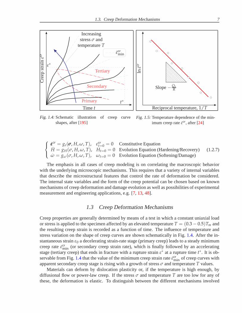
Fig. 1.4:Schematic illustration of creep curveshapes, after [195]
Slope−Qc
R
Reciprocal temperature,1/T
lnεc
r
Fig. 1.5:Temperature dependence of the min-imum creep rateεcr, after [24]
εεεcr = gε(σσσ, H, ω, T), εcrt=0 = 0 Constitutive EquationH = gH(σ, H, ω, T), Ht=0 = 0 Evolution Equation (Hardening/Recovery)ω = gω(σ, H, ω, T), ωt=0 = 0 Evolution Equation (Softening/Damage)
(1.2.7)
The emphasis in all cases of creep modeling is on correlatingthe macroscopic behaviorwith the underlying microscopic mechanisms. This requiresthat a variety of internal variablesthat describe the microstructural features that control the rate of deformation be considered.The internal state variables and the form of the creep potential can be chosen based on knownmechanisms of creep deformation and damage evolution as well as possibilities of experimentalmeasurement and engineering applications, e.g. [7, 13, 48].
1.3 Creep Deformation Mechanisms
Creep properties are generally determined by means of a testin which a constant uniaxial loador stress is applied to the specimen affected by an elevated temperatureT = (0.3− 0.5)Tm andthe resulting creep strain is recorded as a function of time.The influence of temperature andstress variation on the shape of creep curves are shown schematically in Fig.1.4. After the in-stantaneous strainε0 a decelerating strain-rate stage (primary creep) leads to asteady minimumcreep rateεcrmin (or secondary creep strain rate), which is finally followed by an acceleratingstage (tertiary creep) that ends in fracture with a rupture strain ε∗ at a rupture timet∗. It is ob-servable from Fig.1.4that the value of the minimum creep strain rateεcrmin of creep curves withapparent secondary creep stage is rising with a growth of stressσ and temperatureT values.
Materials can deform by dislocation plasticity or, if the temperature is high enough, bydiffusional flow or power-law creep. If the stressσ and temperatureT are too low for any ofthese, the deformation is elastic. To distinguish between the different mechanisms involved
8 1. Basic Assumptions and Motivation
0 0.2 0.4 0.6 0.8 1.010−6
10−5
10−4
10−3
10−2
10−1
Plasticity
Diffusional Flow
(Grain Boundary) (Lattice)
Ela
stic
ity
Power-Law Creep
T/Tm
σ eq/
G
(Low-Temperature Creep)
(High-Temperature Creep)
Theoretical Strength
So
lidu
sTe
mp
erat
ure
Yield Strength
Breakdown
ε4
ε3ε2ε1
ε4 > ε3 > ε2 > ε1
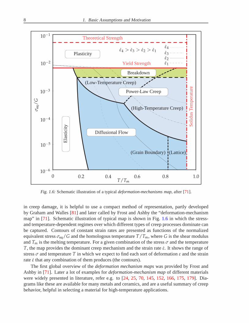
Fig. 1.6:Schematic illustration of a typicaldeformation-mechanisms map, after [71].
in creep damage, it is helpful to use a compact method of representation, partly developedby Graham and Walles [81] and later called by Frost and Ashby the “deformation-mechanismmap” in [71]. Schematic illustration of typical map is shown in Fig.1.6 in which the stress-and temperature-dependent regimes over which different types of creep processes dominate canbe captured. Contours of constant strain rates are presented as functions of the normalizedequivalent stressσeq/G and the homologous temperatureT/Tm, whereG is the shear modulusandTm is the melting temperature. For a given combination of the stressσ and the temperatureT, the map provides the dominant creep mechanism and the strain rateε. It shows the range ofstressσ and temperatureT in which we expect to find each sort of deformationε and the strainrateε that any combination of them produces (the contours).
The first global overview of thedeformation mechanism mapswas provided by Frost andAshby in [71]. Later a lot of examples fordeformation-mechanism mapof different materialswere widely presented in literature, refer e.g. to [24, 25, 70, 145, 152, 166, 175, 179]. Dia-grams like these are available for many metals and ceramics,and are a useful summary of creepbehavior, helpful in selecting a material for high-temperature applications.
1.3. Creep Deformation Mechanisms 9
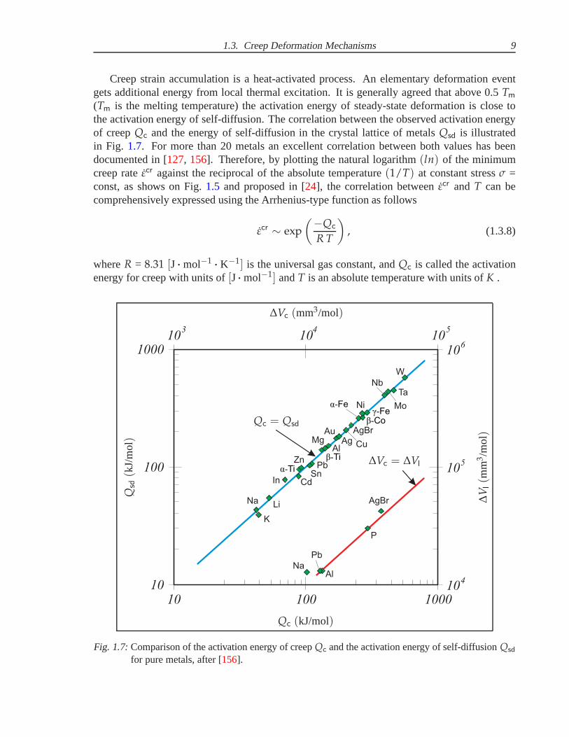
Creep strain accumulation is a heat-activated process. An elementary deformation eventgets additional energy from local thermal excitation. It isgenerally agreed that above 0.5Tm
(Tm is the melting temperature) the activation energy of steady-state deformation is close tothe activation energy of self-diffusion. The correlation between the observed activation energyof creepQc and the energy of self-diffusion in the crystal lattice of metals Qsd is illustratedin Fig. 1.7. For more than 20 metals an excellent correlation between both values has beendocumented in [127, 156]. Therefore, by plotting the natural logarithm(ln) of the minimumcreep rateεcr against the reciprocal of the absolute temperature(1/T) at constant stressσ =const, as shows on Fig.1.5 and proposed in [24], the correlation betweenεcr and T can becomprehensively expressed using the Arrhenius-type function as follows
εcr ∼ exp
(
−Qc
R T
)
, (1.3.8)
whereR = 8.31 [J··· mol−1 ··· K−1] is the universal gas constant, andQc is called the activationenergy for creep with units of[J··· mol−1] andT is an absolute temperature with units ofK .
K
LiNa
In Cd
α-Ti
P
AgBr
Sn
ZnPb
MgAl
AuAg Cu
AgBrβ-Co
γ-Feα-Fe Ni
Nb
W
Mo
10 100 1000
Na
Pb
Al
1000
100
10
10 10 103 4 5
10
10
10
6
5
4
Ta
β-Ti
Qc (kJ/mol)
∆Vc (mm3/mol)
Qsd
(kJ/
mo
l)
∆V
l(m
m3/m
ol)
Qc = Qsd
∆Vc = ∆Vl
Fig. 1.7:Comparison of the activation energy of creepQc and the activation energy of self-diffusionQsd
for pure metals, after [156].
10 1. Basic Assumptions and Motivation
At stressesσ and temperaturesT of interest to the engineer, the following behavior proposedby Norton [157] and Bailey [27] is generally obeyed:
εcr = A σn, (1.3.9)
whereA andn are stress-independent secondary creep constants. An exponential relationship,although not generally used, has also been proposed [183] to explain the behavior at very highstresses, as follows:
εcr = A exp (C σ), (1.3.10)
whereA andC are stress-independent constants.Because creep is a thermally activated process, its temperature sensitivity would be expected
to obey an Arrhenius-type expression (1.3.8), with a characteristic activation energyQc for therate-controlling mechanism. Considering both the stressσ and temperatureT dependencies ofthe creep strain rateεcr, Eq. (1.3.9) can therefore be rewritten as [183]:
εcr = A0 σn exp
(
−Qc
R T
)
, (1.3.11)
whereA0 andn are stress-independent creep constants, andR = 8.314 [J··· K−1 ··· mol−1] is theuniversal gas constant.
Although Eq. (1.3.11) suggests constant values forn andQc, experimental results on steelsshow both of these values to be variable with respect to stress σ and temperatureT. The ex-tended overviews of such experimental results are reportede.g. in [64, 194, 195]. Schematicillustration of creep strain rateεcr vs. stressσ dependence typical for the majority of advancedheat-resistant steels is shown on Fig.1.8. Such a generalization of phenomenological approachto the description of creep behaviour and change of constantn has been proposed to use in[24, 25, 59, 60, 119, 202].
The general approach illustrated on Fig.1.8shows the approximately stepped change in thevalue of creep constantn depending on the level of stressσ corresponding to the defined creep-deformation mechanism. For the all low-alloy and high-alloy heat resistant steels the stressexponentn from Eq. (1.3.11) is decreasing with the decrease of stressσ. But the change ofcreep constantn is stepped, because of the transition from the “power-law breakdown” at highstresses to the “power-law” creep mechanism at moderate stresses. This transition is laboratorywell studied and reported for many low-alloy heat-resistant steels, see e.g. [23, 41, 53, 69,194]. Table1.1 shows the summary of reported experimental data for severallow-alloy steelswith n3 andQ3 as “power-law breakdown” creep constants andn2 andQ2 as creep constantscorresponding to “power-law” mechanism. The reported values of stress exponentn can begeneralized asn3 > 8 for high stress levels and then gradually reducing to2 ≤ n2 ≤ 8 atmoderate stress levels, see Fig.1.8.
With the development of advanced high-alloy steels, the activated creep-deformation mech-anisms corresponding to the same stress levels as for low-alloy steels has changed. The techni-cal operating region for high-alloy steels also includes the change of creep constantn with thedecrease of stressσ. It is caused by the transition from the “power-law” creep athigh stressesto the “linear” creep or diffusional flow mechanism at moderate stresses. This transition is notlaboratory well studied, but never the less some experiments are reported for several high-alloy

1.3. Creep Deformation Mechanisms 11
Diffusional flow or“Harper-Dorn” creep
Power-lawcreep or
“viscous glide”
Power-lawbreakdown
experim
enta
lcre
ep tests
extr
a-
pola
tion
technic
al
opera
ting
regio
n
experim
enta
lcre
ep tests
Cre
epst
rain
rateε
cr
Stressσ
n1 < n2 < n3n1 < n2 < n3n1 < n2 < n3
n1 ∼ 1
2 ≤ n2 ≤ 8
8 ≤ n2 ≤ 12
n3 > 8
n3 > 12
n1
n2
n3
Low-alloy steels:
High-alloy steels:
Fig. 1.8:Schematic illustration of creep rateεcr vs. stressσ dependence, after [24, 25, 59, 60, 119, 202].
Table 1.1:Reported experimental values of secondary creep material parametersni andQi (i = 2, 3) forlow-alloy heat-resistant steels
System of steel Temperature, Low-stress region High-stress region ReferenceC n2 Q2, kJ/mole n3 Q3, kJ/mole
114Cr-1
2 Mo 510–620 4 400 10 625 [194]
214Cr-1Mo 565 2.5 — 12 — [41]
Cr-Mo-V 550–600 4.9 326 14.3 503 [69]
Fe-V-C 440–575 2.7 304 9.5 620 [53]
Cr-Ni-Mn 600–750 1.5–2 400-470 5.6 — [23]
heat-resistant steels, see e.g. [31, 106, 109, 110, 138, 187, 193]. Table1.2shows the summaryof reported experimental data for several high-alloy steels withn2 andQ2 as “power-law” creepconstants andn1 andQ1 as creep constants corresponding to the “linear” creep mechanism. Thereported values of stress exponentn can be generalized as8 ≤ n2 ≤ 12 for high stress levelsand then gradually reducing ton1 ∼ 1 at moderate stress levels, see Fig.1.8.
Although many investigators report a distinct break in the curve presenting creep strain rate
12 1. Basic Assumptions and Motivation
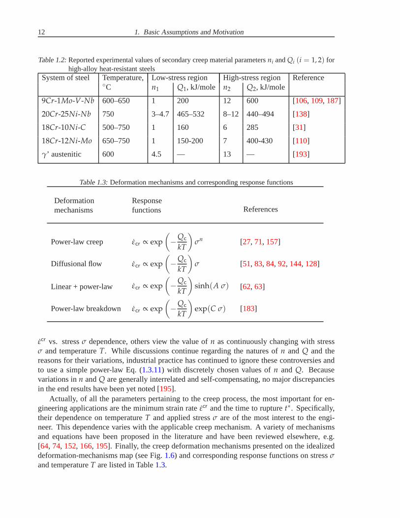
Table 1.2:Reported experimental values of secondary creep material parametersni andQi (i = 1, 2) forhigh-alloy heat-resistant steels
System of steel Temperature, Low-stress region High-stress region ReferenceC n1 Q1, kJ/mole n2 Q2, kJ/mole
9Cr-1Mo-V-Nb 600–650 1 200 12 600 [106, 109, 187]
20Cr-25Ni-Nb 750 3–4.7 465–532 8–12 440–494 [138]
18Cr-10Ni-C 500–750 1 160 6 285 [31]
18Cr-12Ni-Mo 650–750 1 150-200 7 400-430 [110]
γ’ austenitic 600 4.5 — 13 — [193]
Table 1.3:Deformation mechanisms and corresponding response functions
Deformationmechanisms
Responsefunctions References
Power-law creep εcr ∝ exp
(
−Qc
kT
)
σn [27, 71, 157]
Diffusional flow εcr ∝ exp
(
−Qc
kT
)
σ [51, 83, 84, 92, 144, 128]
Linear + power-law εcr ∝ exp
(
−Qc
kT
)
sinh(A σ) [62, 63]
Power-law breakdown εcr ∝ exp
(
−Qc
kT
)
exp(C σ) [183]
εcr vs. stressσ dependence, others view the value ofn as continuously changing with stressσ and temperatureT. While discussions continue regarding the natures ofn and Q and thereasons for their variations, industrial practice has continued to ignore these controversies andto use a simple power-law Eq. (1.3.11) with discretely chosen values ofn and Q. Becausevariations inn andQ are generally interrelated and self-compensating, no major discrepanciesin the end results have been yet noted [195].
Actually, of all the parameters pertaining to the creep process, the most important for en-gineering applications are the minimum strain rateεcr and the time to rupturet∗. Specifically,their dependence on temperatureT and applied stressσ are of the most interest to the engi-neer. This dependence varies with the applicable creep mechanism. A variety of mechanismsand equations have been proposed in the literature and have been reviewed elsewhere, e.g.[64, 74, 152, 166, 195]. Finally, the creep deformation mechanisms presented on the idealizeddeformation-mechanisms map (see Fig.1.6) and corresponding response functions on stressσand temperatureT are listed in Table1.3.

1.4. Creep and Damage Models 13
nnn
nnn
A0
Aω
I
II
IIIMacrocracks
Microcracks
Orientated CavitiesIsolated Cavities
AB
C
D
A — observation B — observation, fixed inspection intervalsC — limited service until repair D — immediate repair
Time t
Str
ain
ε
instantaneous elastic strainεel
cree
pst
rainε
cr
min. creep rateεcrmintime to
fracturet∗
Fracture
Creep damage startsDamage accumulates
rup
ture
stra
inε∗
Fig. 1.9:Evolution of damage caused by creep and corresponding service operations in a high-temperature component, after [154].
1.4 Creep and Damage Models
A typical creep behaviour of metals and alloys is accompanied by time-dependent creep defor-mations and damage processes induced by the nucleation and the growth of microscopic cracksand cavities. In order to characterise the evolution of the material damage as well as to describethe increase in creep strain rate during tertiary creep the continuum damage mechanics has beenestablished and demonstrated to be a powerful approach, e.g. [89]. A lot of applications of creepcontinuum damage mechanics are related to the long-term predictions in thin-walled structures,e.g. pipes or pipe bends used in power and chemical plants. Here follows the short introductioninto the continuum damage mechanics.
Damage accumulates in the form of internal cavities during creep. The damage first appearsat the start of thetertiary stageof the creep curve and grows at an increasing rate thereafter. Theshape of thetertiary stageof the creep curve (see Fig.1.2) reflects this: as the cavities grow,the cross-section of the specimen decreases, and at constant load the stressσ goes up. Sinceεcr ∝ σn, the creep rateεcr goes up even faster than the stressσ does caused by creep damage,as illustrated on Fig.1.9.
Isotropic damage models are generally formulated using thethe concept of the effectivestressσ, see e.g. [34, 124, 152, 166]. In the uniaxial case this concept is formulated as fol-lows. Previous studies incontinuum damage mechanicsstarts with the concept ofcontinuityψnnn
introduced by Kachanov [100]:
ψnnn =A0 − Aω
A0, (1.4.12)
where A0 denotes the cross section of a uniaxial specimen,Aω is the cross section area of

14 1. Basic Assumptions and Motivation
cavities, andnnn is the normal vector to the cross-section, as illustrated onFig. 1.9. Using theEq. (1.4.12) a virgin state is characterized withψnnn = 1, a fracture is characterized withψnnn = 0,an isotropic damage is described withψ ≡ ψnnn, and for the damaged state thecontinuityψnnn liesin the range1 ≥ ψnnn ≥ 0.
Later the concept ofcontinuityψnnn was extended to the concepts of scalar state variableω,e.i. isotropicdamageparameterω, which characterises a damage state of a material loaded bythe stressσ. Specifying byω the area fraction of cavities
ω = Aω/A0 ≡ 1 − ψ, (1.4.13)
one can introduce theeffective stressor net stressσ by dividing the applied forceF to theeffective areaor net area
A = A0 − Aω = A0(1 − ω). (1.4.14)
As a result the effective stress was defined by Rabotnov in [171] as follows:
σ =F
A=
F
A0(1 − ω)=
σ
(1 − ω). (1.4.15)
In [171] Rabotnov pointed out that the damage state variableω “may be associated withthe area fraction of cracks, but such an interpretation is connected with a rough scheme and istherefore not necessary”. Rabotnov assumed that the creep rate is additionally dependent on thecurrent damage state. The constitutive equation should have the form
εcr = εcr(σ, ω). (1.4.16)
Furthermore, the damage processes can be reflected in the evolution equation
ω = ω(σ, ω), ω|t=0 = 0, ω < ω∗, (1.4.17)
whereω∗ is the critical value of the damage parameter for which the material fails. With thepower functions of stress and damage the constitutive equation may be formulated as follows
εcr =A σn
(1 − ω)m, (1.4.18)
accompanied by the damage evolution equation in the form
εcr =B σk
(1 − ω)l, (1.4.19)
whereA, B, n, m, l, k are the material dependent creep parameters.These Eqs (1.4.18) and (1.4.19) can be only applied to the case of constant temperatureT.
To generalize them to the non-isothermal conditions the material constantsA andB should bereplaced by the functions of temperatureT. Assuming the Arrhenius-type temperature depen-dence (1.3.8) the following relations can be utilized [152]
A(T) = A0 exp
(
−Qc
R T
)
and B(T) = B0 exp
(
−Qd
R T
)
, (1.4.20)
1.4. Creep and Damage Models 15
whereQc andQd are the activation energies of creep and damage processes, respectively.To identify the material constants in Eqs (1.4.18) - (1.4.20) experimental data of uni-axial
creep up to rupture for certain stress and temperature ranges are required. The identificationprocedure is presented e.g. in [114]. If to limit to the case of fixed temperature and to assumem = n in Eq. (1.4.18), then the uni-axial creep model takes the form [152]
εcr = A
(
σ
1 − ω
)n
and ω =B σk
(1 − ω)l(1.4.21)
The model (1.4.21) was applied for the creep-damage description of transversely loadedshells and plates, presented e.g. in [13, 14, 15, 18, 19, 35, 52], and creep of several steels pipesand welded structures, e.g. in [42, 96, 151, 152]. The isotropic damage concept is suitable tocharacterise the creep-damage behaviour of some materialslike steels and aluminium alloys[45] and is applicable for simple stress states typically realised in uniaxial creep tests [37, 143].
Dyson and McClean proposed in [62] the following modification of the Kachanov-Rabotnovcreep-damage model, which fits all creep stages and it is mainly used for the creep modellingof low alloy ferritic steels and Ni-base alloys:
εcr = εcr0 (1 + Dd) exp
(
−Q
R T
)
sinh
(
σ (1 − H)
σ0 (1 − Dp) (1 − ω)
)
, (1.4.22)
whereεcr andεcr0 are the equivalent minimum creep strain rate and the reference creep strain rate;σ andσ0 are the equivalent stress and the reference stress, respectively; T is the temperature;Qis the creep activation energy;H, Dd, Dp, ω are internal state variables, defined by evolutionequations. Notably,H is the hardening parameter,Dd is the damage parameter caused bymultiplication of mobile dislocations,Dp is the damage parameter caused by particle coarseningandω is the damage parameter caused by the cavity nucleation and growth.
There are unlimited possibilities to extend the constitutive equations. As one example canserve the model [167], in which the additional number of creep parameters, determining damagemechanisms and corresponding temperature dependencies, are introduced. A set of constitutiveequations have been derived with an associated set of temperature dependencies, which de-scribe the accumulation of intergranular cavitation, the coarsening of carbide precipitates andthe influence of these mechanisms on the effective creep strain rate
εe = A sinh
[
Bσe (1 − H)
(1 − Φ) (1 − ω)
]
, ω = CNεe
(
σ1
σe
)ν
, (1.4.23)
H =
(
hεe
σe
)(
1 −H
H∗
)
, Φ =
(
Kc
3
)
(1 − Φ)4 ,
A = A0 B exp
(
−QA
R T
)
, B = B0 exp
(
−QB
R T
)
,
Kc =
(
Kc0
B3
)
exp
(
−QKC
R T
)
, C = C0 exp
(
−QC
R T
)
,
whereN = 1 for σ1 > 0 andN = 0 for σ1 ≤ 0; A0, B0, C0, Kc0, h, H∗, QA, QB, QC andQKC
are material constants to be determined from uniaxial creepdata over a range of stresses and oftemperatures; the constantν is determined from multi-axial creep rupture data [167].
16 1. Basic Assumptions and Motivation
1.5 Scope and Motivation
In recent years a lot of industrial and scientific organizations work intensively for improvedmodeling and experimental investigation of creep-damage behavior of heat-resistant materialsused in high-temperature equipment components of power-generation plants, chemical facili-ties, heat engines, etc. Among them are European Creep Collaborative Committee, see e.g. [93,139], Forschungszentrum Karlsruhe (Germany), see e.g. [117, 176, 177], Institute of Physics ofMaterials Brno (Czech Republic), see e.g. [105, 106, 107, 108, 109, 110, 165, 185, 186, 187],Materialprufungsanstalt Stuttgart (Germany), see e.g. [75, 104, 133, 196], Oak Ridge NationalLaboratory (USA), see e.g. [111, 137], National Research Institute for Metals (Japan), see e.g.[5, 6, 118, 162, 163, 164, 201], National Aeronautics and Space Administration (USA), seee.g. [173, 174], etc. At present, a large number of creep models, which are able to describeuniaxial creep curves for certain stress and temperature ranges, have been developed and prac-tically applied for creep estimations and life-time assessments. Only few of them are foundapplicable to the FEM-based creep modeling for structural analysis and life-time assessmentunder multi-axial stress states, because of their different initial designations and correspondingmathematical and mechanical limitations. Therefore, all the basic approaches to the descrip-tion of creep behavior can be conventionally systematized on four main groups as proposedin [147, 152]: 1) empirical models, 2) materials science models, 3) micro-mechanical models,4) continuum mechanics models.
Within the frames and objectives of this work thecontinuum mechanics modelsare of themost interest. The objective ofcontinuum mechanics modelingis to investigate creep in ide-alized three-dimensional solids. The idealization is related to the hypothesis of a continuum,e.g. refer to [85]. The approach is based on balance equations and assumptions regarding thekinematics of deformation and motion. Creep behavior is described by means of constitutiveequations which relate deformation processes and stresses. Details of topological changes ofmicrostructure like subgrain size or mean radius of carbideprecipitates are not considered. Theprocesses associated with these changes like hardening, recovery, ageing and damage can betaken into account by means of hidden or internal state variables and corresponding evolu-tion equations, see e.g. [34, 126, 172, 189]. Creep constitutive equations with internal statevariables can be applied to structural analysis. Various models and methods recently devel-oped within the mechanics of structures can be extended to the solution of creep problems.Examples are theories of rods, plates and shells as well as direct variational methods, e.g.[11, 34, 40, 135, 152, 168, 190]. Numerical solutions by the finite element method combinedwith various time step integration techniques allow to simulate time dependent structural behav-ior up to critical state of failure. Examples of recent studies include circumferentially notchedbars [87], pipe weldments [91] and thin-walled tubes [117]. In these investigations qualitativeagreements between the theory and experiments carried out on model structures have been es-tablished. Constitutive equations with internal state variables have been found to be mostlysuited for the creep analysis of structures [91]. However, it should be noted that this approachrequires numerous experimental data of creep for structural materials over a wide range of stressand temperature as well as different complex stress states.
This thesis is a contribution to the continuum mechanics modeling of creep and damage withthe aim of structural analysis of industrial components andstructures. This type of modeling is
1.5. Scope and Motivation 17
related to the both fields of “creep mechanics” [34, 160] and “continuum damage mechanics”[89] and requires the following steps [40, 94, 147, 152, 159]:
• formulation of a constitutive model including creep constitutive equation and evolutionequations for internal state variables (e.g. damage, softening, hardening, etc.) to reflectbasic features of creep behavior of a structural material under multi-axial stress states,
• identification of creep material parameters in constitutive and evolution equations basedon experimental data of creep and long-term strength at several temperatures,
• development of geometrical model of analysed structure or application of a structuralmechanics model by taking into account creep processes and stress state effects,
• formulation of an initial-boundary value problem based on the creep constitutive andstructural mechanics models with initial and boundary conditions,
• application of finite element method or development of numerical solution procedures,
• verification of obtained results as well as the numerical methods and algorithms.
The principal aim of this work is the development of a comprehensive creep-damage constitu-tive model based on continuum mechanics approach, then the following significant problemsand questions of constitutive modeling must be taken into account:
• Applicability to wide ranges of temperature and stress.The constitutive and evolutionequations are formulated as phenomenological dependencies on stress and temperature.According to experimental studies many materials for high-temperature applications ex-hibit a stress and temperature ranges dependent creep behavior. The European andJapanese material research results show that, especially for new steels in the class of9-12%Cr, long-term creep-rupture testing of> 50 000 h under low stresses is required todetermine the real alloy behaviour, e.g. refer to [101, 118]. Otherwise a very dangerousoverestimation of the material stability can result as shown in different publications ifcomparing long-term extrapolations on the basis of either short or long term tests. Thus,the response functions of the applied stress and temperature in constitutive and evolu-tions equations should extrapolate the laboratory creep and rupture data usually obtainedunder increased stress and temperature to the in-service loading conditions relevant forindustrial applications.
• Ability to model tertiary creep stage. The aim of creep modeling is to reflect basic featuresof creep in structures including the development of inelastic deformations, relaxation andredistribution of stresses as well as the local reduction ofmaterial strength. A modelshould be able to account for material degradation processes in order to predict long-termstructural behavior, i.e. time-to-fracture, and to analyze critical zones of creep failure.
• Minimum quantity of creep material parameters.Conventional constitutive models con-tain the large number of parameters which must be identified by the way of complex, longand expensive experiments. Such situation results to high necessity for development of

18 1. Basic Assumptions and Motivation
models with a small number of parameters at preservation accuracy, sufficient for practi-cal purposes. Effective way of creation of such models is thecombination of approachesof continuum mechanics with qualitative conclusions of physics of creep of metals.
• Simplicity of creep parameters identification.Depending on the choice of creep-damagemodel the main problem is the creep parameter identificationfor the corresponding ma-terial. The significant scatter of properties of creep demands a lot number of experimentsfor statistical processing of experimental results. For parameter identification even simpleconstitutive models require a considerable number of experiments both under uni-axialand multi-axial loading. Thus, the creep material parameters for a selected constitutivemodel must be derived from the standard procedures for creepuni-axial testing.
• Compatibility with commercial FEM-based software.Commercial finite element codeslike ABAQUS and ANSYS were developed to solve various problems in solid mechanics.In application to the creep analysis one should take into account that a general purposeconstitutive equation which allows to reflect the whole set of creep and damage processesin structural materials over a wide range of loading and temperature conditions is notavailable at present in commercial FEM-based software. Therefore, a specific constitu-tive model with selected internal state variables, specialtypes of stress and temperaturefunctions as well as material constants identified from available experimental data shouldbe incorporated into the commercial finite element code by writing a user-defined materialsubroutine [152]. Furthermore, the constitutive model must be compatible with standardprogramming languages (e.g. FORTRAN, C++, PYTHON) and easyto be translated intoprogramming code.
Therefore, within the framework of the dissertation a comprehensive non-isothermal creep-damage model based on continuum mechanics approach and applicable to a wide stress rangehave to be developed. The model must rely on the material science assumptions about variouscreep-deformation behavior in a wide stress range and experimental observations showing thechanges of material microstructure caused by long-term thermal exposure and creep deforma-tions. In addition, it must contain a minimum of creep material parameters, which are easyidentified from the standard procedures for creep and rupture uni-axial testing. For the pur-pose of effective application to numerical structural analysis in FEM-based software the modelshould be presented in the form of a user-defined material subroutine coding.

2. CONVENTIONAL APPROACH TO CREEP-DAMAGE MODELING
In Chapter1 we discussed theoretical approaches to the constitutive modeling of creep behavior.Chapter2 presents the conventional approaches to creep-damage modeling, which are appliedto several engineering materials. The models include specific forms of the constitutive equa-tion for the creep rate tensor and evolution equations for internal state variables. In addition,constitutive functions of stress and temperature are specified. In order to find a set of mate-rial constants creep tests under constant load and temperature leading to a homogeneous stressstate are required. The majority of available experimentaldata is presented as creep strain ver-sus time curves from standard uni-axial tests. Based on these experimental curves the creepmaterial parameters are identified.
Section2.1 is devoted to description of the conventional isotropic Kachanov-Rabotnov-Hayhurst creep-damage model based on continuum damage mechanics, see e.g. [89, 100, 171].The model is extended to the case of variable temperature andstrain hardening consideration[114]. Both the creep and the damage rates are assumed temperature dependent. A techniquefor the identification of material creep parameters for the model based on the available familyof experimental creep curves is presented in AppendixA. The model was applied to the numer-ical long-term strength analysis and life-time assessmentunder the creep conditions of severaltypical power-generation plant components [79, 114, 129, 130, 131, 132].
The objective of Sect.2.2.1 to develop a model for anisotropic creep behavior in a weldmetal produced by multi-pass welding. The anisotropy of creep properties is caused the com-plex directional microstructure of weld metal induced by the heat affect [95]. The structuralanalysis of a welded joint requires a constitutive equationof creep for the weld metal undermulti-axial stress states. For this purpose we apply the approaches to modeling of creep for ini-tially anisotropic materials. The outcome is the a creep constitutive equation for the strain ratetensor describing secondary and tertiary creep behavior. It is accompanied by the two damageevolution equations describing the different damage accumulation in the longitudinal directionand in the transverse plane of isotropy. The material constants are identified according to theexperimental data presented in the literature [95]. The model was verified applying it to thenumerical long-term strength analysis of a typical T-piecepipe weldment [80].
Since the nature of damage phenomenon is generally anisotropic, the isotropic materialdamage is just a simplified case of the damage anisotropy. Then it is necessary to highlightin Sect.2.2.2the Murakami-Ohno creep-damage model with damage induced anisotropy. Theanisotropic creep behaviour induced by damage is characterised by introducing a tensor-valuedinternal state variable. We should discuss the anisotropicdamage concept proposed by Mu-rakami and Ohno [142] in order to conclude about the influence of damage induced anisotropyon the long-term predictions in high-temperature engineering applications, e.g. [13, 79].

20 2. Conventional approach to creep-damage modeling
2.1 Non-isothermal isotropic creep-damage model
The conventional isotropic creep-damage model by Kachanov[100], Rabotnov [171] and Hay-hurst [89] is based on the continuum damage mechanics. It contains thepower-law stress re-sponse function and a scalar damage parameter. The conventional model is extended to thecase of variable temperature and strain hardening consideration. Both the creep and the damagerates are assumed temperature dependent using the Arrhenius-type functions. The constitutivemodel is able to describe the primary, secondary and tertiary stages of creep behavior. Both theuni-axial and the multi-axial forms of the model accompanied with a technique for the identifi-cation of material creep parameters based on the available family of experimental creep curvesat various temperatures and wide stress range are presentedbelow.
2.1.1 Uni-axial stress state
The Kachanov-Rabotnov-Hayhurst model and physical mechanisms of creep for typical heat-resistant steels build the basis for the here suggested non-isothermal creep-damage model. Theprimary creep is characterized by the introduction of the following strain hardening function:
H(εcr) = 1 + C exp
(
−εcr
k
)
. (2.1.1)
In order to reflect various influences of temperature on the diffusional creep and the crossslip dislocation two different functional dependences areintroduced in the constitutive creepstrain rate equation and in the evolution equation determining the damage rate. For the descrip-tion of temperature dependence the Arrhenius functions [167] are introduced:
A(T) = A exp
(
−Qα
R T
)
and B(T) = B exp
(
−Qβ
R T
)
. (2.1.2)
The uni-axial form of creep-damage equations considering strain hardening for variabletemperature field is given in the following form
dεcr
dt= A(T) H(εcr)
[
σ
1 − ω
]n
, (2.1.3)
dω
dt= B(T)
σm
(1 − ω)l. (2.1.4)
In Eqs (2.1.1) - (2.1.4) εcr represents the creep strain;t denotes time;σ is the uniaxial stress;Qα andQβ are energies of activation;T is the absolute temperature;A, B, C, n, m, k, l are thematerial constants;ω is the scalar damage parameter(0 ≤ ω ≤ ω∗), whereω∗ is the criticalvalue of damage corresponding to the time of rupturet∗.
Instead of three constants including the energies of activation of creep and damage processesand universal gas constant the following two constants are introduced:
h =Qα
Rand p =
Qβ
R. (2.1.5)

2.1. Non-isothermal isotropic creep-damage model 21
In the general case, the values of thermal energies of activation for creep processQα andfor damage processQβ of the typical heat-resistant steel are different. Together with the othermaterial constants, they are estimated from the set of experimental creep curves within a widerange of temperatures and stresses.
The time integration of the damage evolution equation (2.1.4) under assumption of the fixedstress and temperature provides the functionω(t) as follows:
ω(t) = 1 −
[
1 − (l + 1) B exp
(
−p
T
)
σm t
]1
l+1
. (2.1.6)
Therefore, time-to-rupturet∗ can be defined with assumption thatω = 1 as follows:
t∗ =1
[
(l + 1) B exp(
−pT
)
σm] . (2.1.7)
By taking into account the time-dependent functionω(t) in the form of Eq. (2.1.6), thecreep constitutive equation (2.1.3) is integrated by time as follows
εcr(t) = k ln
[
(1 + C) exp
(
ζ(t)
k
)
− C
]
, (2.1.8)
where the auxiliary time-dependent functionζ(t) is defined in the following form:
ζ(t) =A exp
(
p−hT
)
σn−m
B (n − l − 1)
[
1 − (l + 1) B exp(
−p
T
)
σm t]
l−n+1l+1
− 1
. (2.1.9)
The procedure of material creep constants identification under the constant temperature isdescribed in [77]. For the identification of values for the activation energies of creep-damageprocesses, i.e. creep constantsh and p, it is necessary to have experiment data under at leasttwo differents values of temperatureT. If the experimental data is available for more than twotemperatureT values, than the identification procedure cited in [114] must be applied. Thetypical creep material parameters identification procedure for the uniaxial form (2.1.3) - (2.1.4)of conventional non-isothermal creep-damage model is highlighted in AppendixA.
For the creep rupture time assessment, which is principallydefined by secondary and tertiarycreep stages, it is possible to apply the simplified version of creep-damage model by neglectingthe primary creep stage, i.e. by settingH (εcr) = 1. Further simplification can be made byequating the tertiary creep constantsm = l. Such a model contains only 6 material constants,which can be easily determined from experimental data.
2.1.2 Multi-axial stress state
The internal material state variables and the form of the creep potential of the constitutive modelfor isotropic creep behaviour can be chosen based on known mechanisms of creep deformationand damage evolution [7]. According to known deformation mechanisms the primary and sec-ondary creep rates are dominantly controlled by the von Mises effective stress. The tertiarycreep stage, accelerated by damage, is additionally influenced by the kind of the stress state.

22 2. Conventional approach to creep-damage modeling
The conventional isotropic creep-damage model by Kachanov-Rabotnov-Hayhurst is basedon the power-law stress function and a scalar damage parameter, with a constitutive equation
εεεcr =3
2
εcreqσvM
sss, (2.1.10)
where the equivalent creep strain rate have following form
εcreq = A exp
(
−h
T
) [
1 + C exp
(
−εcreqk
)] (
σvM
1 − ω
)n
, (2.1.11)
and the evolutional equation for a scalar damage parameter is formulated as follows
ω = B exp(
−p
T
)
(⟨
σωeq
⟩)m
(1 − ω)l. (2.1.12)
In notations (2.1.10) - (2.1.12) εεεcr represents the creep strain rate tensor;σvM =[
32 sss · · sss
]
12
is the effective von Mises stress;sss is the stress deviator;A, B, n, m, l are creep materialparameters;ω is an isotropic damage parameter(0 ≤ ω ≤ ω∗), σω
eq is the damage equivalentstress, used in the form proposed by Leckie and Hayhurst in [121]
σωeq = ασI + (1 − α) σvM, (2.1.13)
whereσI is a maximum principal stress,α is a weighting factor considering the influence ofdamage mechanisms (σI-controlled orσvM-controlled).
The creep-damage model (2.1.10) - (2.1.12) fulfils the condition of incompressibility. Fur-thermore, the damage evolution is assumed only for the positive equivalent stress
⟨
σωeq
⟩
= σωeq for σω
eq > 0 and⟨
σωeq
⟩
= 0 for σωeq ≤ 0. (2.1.14)
2.2 Anisotropic creep-damage models
2.2.1 Model for anisotropic creep in a multi-pass weld metal
The lifetime to fracture of high-temperature components offossil power plants and chemicalfacilities structures is defined by irreversible processesof creep and damage. The most danger-ous and the probable place of rupture in welded structures ofpipelines or high-pressure vesselsis the weldment zone. The reason of that fact is a complex and non-uniform microstructure ofthe material in the weldment zone caused by the manufacturing process of multi-pass welding.It is possible to define at least three main zones: weld metal,adjacent heat-affected zone andparent material of a welded structure (see Fig.2.1), as described in [96, 152].
The principal purposes of creep-damage modeling for weldedstructures are:
• the long-term prediction of stress redistribution in a local weldment zone having complexgeometry as a result of creep strain,

2.2. Anisotropic creep-damage models 23
Multipass weldingprocess
Intercritical zone
Fine grained zoneCoarse grained zone
Weld metal(WM)
Heat-affected zone(HAZ)
Parent material(PM)
WM
WM
PM
PM
HAZ
HAZ
Stress-strain behavior(room temperature)
Creep behavior(T = 0.5 − 0.7 Tm)
TimeStrain
Str
ess
Cre
epst
rain
Fig. 2.1:Typical microstructure of welded joint and material behavior, after [151, 152].
• an estimation of probable zones with critical damage accumulation that could lead tofracture and crack initiation.
Particularly, creep modeling allows to predict zones of unexpected fracture and for the pur-pose of inspection of some structural components during thethe service and to estimate theresidual lifetime of a structure. Description and methodology of in-service inspections for high-temperature power and chemical plant components can be found e.g. in [43].
Analysis of literature
One of the possibilities to model creep process in welded structures is to use the concepts ofcontinuum damage mechanics which provide constitutive equation for the creep strain rate ten-sor, damage evolution equation and evolution equations forother material state variables, e.g.hardening, softening, etc. These equations are complemented with non-linear initial-boundaryproblem to analyze the long-term strength of structures, see e.g. [13, 89]. The practical experi-ence and approaches to creep modeling in welded structures using FEM during the last 10 yearscan be found in [91, 96, 184]. According to that approaches the weldment volume was dividedon three zones considering different material behavior under the creep conditions (see Fig.2.2).
24 2. Conventional approach to creep-damage modeling
0 100 200 300 400 500 600 700 800
0.05
0.04
0.03
0.02
0.01
0
Time (t), h
Cre
epst
rain
(εcr )
Parent (base) material
Heat-affected zone
Weld metal (longitudinal)
Weld metal (transversal)
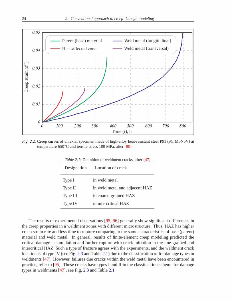
Fig. 2.2:Creep curves of uniaxial specimen made of high-alloy heat-resistant steel P91 (9CrMoNbV) attemperature 650C and tensile stress 100 MPa, after [80].
Table 2.1:Definition of weldment cracks, after [47].
Designation Location of crack
Type I in weld metal
Type II in weld metal and adjacent HAZ
Type III in coarse-grained HAZ
Type IV in intercritical HAZ
The results of experimental observations [95, 96] generally show significant differences inthe creep properties in a weldment zones with different microstructure. Thus, HAZ has highercreep strain rate and less time to rupture comparing to the same characteristics of base (parent)material and weld metal. In general, results of finite-element creep modeling predicted thecritical damage accumulation and further rupture with crack initiation in the fine-grained andintercritical HAZ. Such a type of fracture agrees with the experiments, and the weldment cracklocation is of type IV (see Fig.2.3and Table2.1) due to the classification of for damage types inweldments [47]. However, failures due cracks within the weld metal have been encountered inpractice, refer to [95]. These cracks have types I and II in the classification scheme for damagetypes in weldments [47], see Fig.2.3and Table2.1.
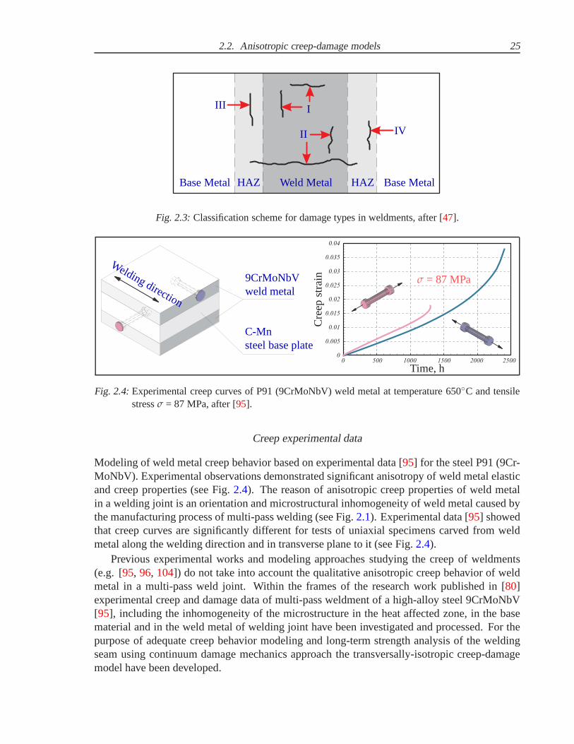
2.2. Anisotropic creep-damage models 25
Base MetalBase Metal HAZHAZ Weld Metal
I
II
III
IV
Fig. 2.3:Classification scheme for damage types in weldments, after [47].
0 500 1000 1500 2000 2500
0.04
0.035
0.03
0.025
0.02
0.015
0.01
0.005
0
σ = 87 MPa
Time, h
Cre
epst
rain
9CrMoNbVweld metal
C-Mnsteel base plate
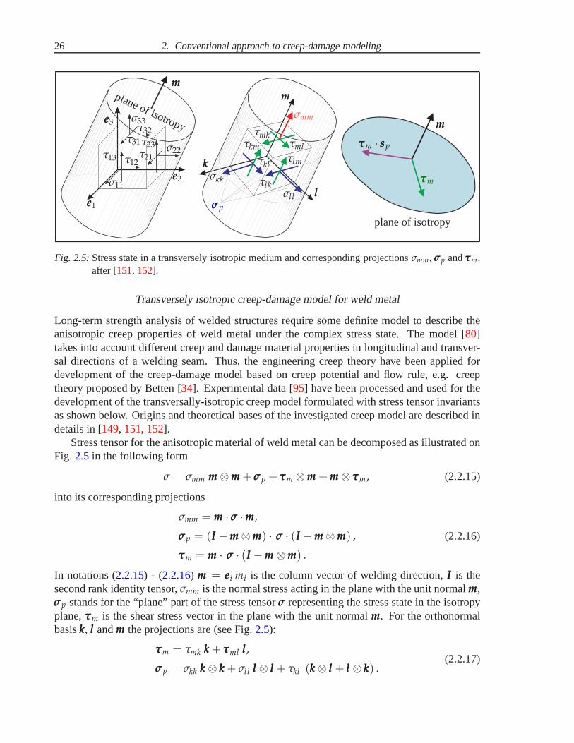
Welding direction
Fig. 2.4:Experimental creep curves of P91 (9CrMoNbV) weld metal at temperature 650C and tensilestressσ = 87 MPa, after [95].
Creep experimental data
Modeling of weld metal creep behavior based on experimentaldata [95] for the steel P91 (9Cr-MoNbV). Experimental observations demonstrated significant anisotropy of weld metal elasticand creep properties (see Fig.2.4). The reason of anisotropic creep properties of weld metalin a welding joint is an orientation and microstructural inhomogeneity of weld metal caused bythe manufacturing process of multi-pass welding (see Fig.2.1). Experimental data [95] showedthat creep curves are significantly different for tests of uniaxial specimens carved from weldmetal along the welding direction and in transverse plane toit (see Fig.2.4).
Previous experimental works and modeling approaches studying the creep of weldments(e.g. [95, 96, 104]) do not take into account the qualitative anisotropic creep behavior of weldmetal in a multi-pass weld joint. Within the frames of the research work published in [80]experimental creep and damage data of multi-pass weldment of a high-alloy steel 9CrMoNbV[95], including the inhomogeneity of the microstructure in theheat affected zone, in the basematerial and in the weld metal of welding joint have been investigated and processed. For thepurpose of adequate creep behavior modeling and long-term strength analysis of the weldingseam using continuum damage mechanics approach the transversally-isotropic creep-damagemodel have been developed.
26 2. Conventional approach to creep-damage modeling
mmmmmm
mmm
kkk
lll
plane of isotropy
plane of isotropy
τττm
τττm · sssp
eee1
eee2
eee3σmm
σσσp
σkk
σll
τmkτkm
τkl
τlk
τml
τlm
σ11
σ22
σ33
τ13
τ31
τ12τ21
τ23
τ32
Fig. 2.5:Stress state in a transversely isotropic medium and corresponding projectionsσmm, σσσp andτττm,after [151, 152].
Transversely isotropic creep-damage model for weld metal
Long-term strength analysis of welded structures require some definite model to describe theanisotropic creep properties of weld metal under the complex stress state. The model [80]takes into account different creep and damage material properties in longitudinal and transver-sal directions of a welding seam. Thus, the engineering creep theory have been applied fordevelopment of the creep-damage model based on creep potential and flow rule, e.g. creeptheory proposed by Betten [34]. Experimental data [95] have been processed and used for thedevelopment of the transversally-isotropic creep model formulated with stress tensor invariantsas shown below. Origins and theoretical bases of the investigated creep model are described indetails in [149, 151, 152].
Stress tensor for the anisotropic material of weld metal canbe decomposed as illustrated onFig. 2.5in the following form
σ = σmm mmm ⊗mmm + σσσp + τττm ⊗mmm + mmm ⊗ τττm, (2.2.15)
into its corresponding projections
σmm = mmm · σσσ ·mmm,
σσσp = (III −mmm ⊗mmm) · σσσ · (III −mmm ⊗mmm) ,
τττm = mmm · σσσ · (III −mmm ⊗mmm) .
(2.2.16)
In notations (2.2.15) - (2.2.16) mmm = eeei mi is the column vector of welding direction,III is thesecond rank identity tensor,σmm is the normal stress acting in the plane with the unit normalmmm,σσσp stands for the “plane” part of the stress tensorσσσ representing the stress state in the isotropyplane,τττm is the shear stress vector in the plane with the unit normalmmm. For the orthonormalbasiskkk, lll andmmm the projections are (see Fig.2.5):
τττm = τmk kkk + τττml lll,
σσσp = σkk kkk ⊗ kkk + σll lll ⊗ lll + τkl (kkk ⊗ lll + lll ⊗ kkk) .(2.2.17)
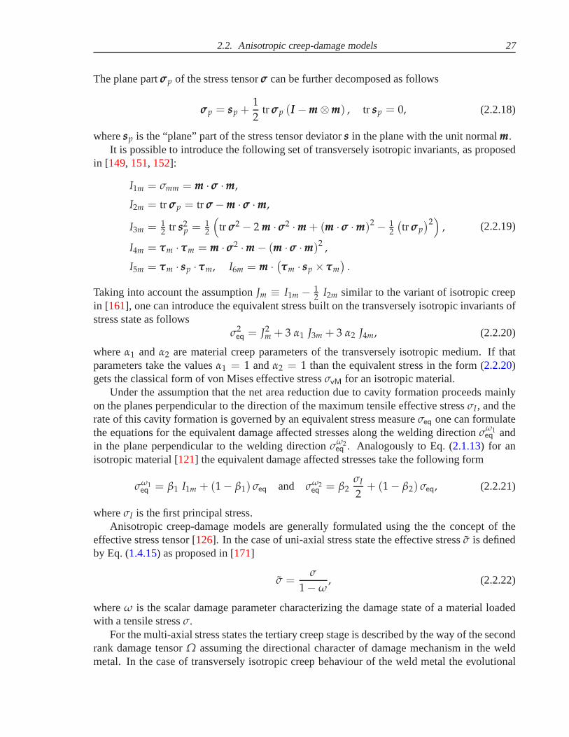
2.2. Anisotropic creep-damage models 27
The plane partσσσp of the stress tensorσσσ can be further decomposed as follows
σσσp = sssp +1
2tr σσσp (III −mmm ⊗mmm) , tr sssp = 0, (2.2.18)
wheresssp is the “plane” part of the stress tensor deviatorsss in the plane with the unit normalmmm.It is possible to introduce the following set of transversely isotropic invariants, as proposed
in [149, 151, 152]:
I1m = σmm = mmm · σσσ ·mmm,
I2m = tr σσσp = tr σσσ −mmm · σσσ ·mmm,
I3m = 12 tr sss2
p = 12
(
tr σσσ2 − 2 mmm · σσσ2 ·mmm + (mmm · σσσ ·mmm)2 − 12
(
tr σσσp
)2)
,
I4m = τττm · τττm = mmm · σσσ2 ·mmm − (mmm · σσσ ·mmm)2 ,
I5m = τττm · sssp · τττm, I6m = mmm ·(
τττm · sssp × τττm
)
.
(2.2.19)
Taking into account the assumptionJm ≡ I1m − 12 I2m similar to the variant of isotropic creep
in [161], one can introduce the equivalent stress built on the transversely isotropic invariants ofstress state as follows
σ2eq = J2
m + 3 α1 J3m + 3 α2 J4m, (2.2.20)
whereα1 andα2 are material creep parameters of the transversely isotropic medium. If thatparameters take the valuesα1 = 1 andα2 = 1 than the equivalent stress in the form (2.2.20)gets the classical form of von Mises effective stressσvM for an isotropic material.
Under the assumption that the net area reduction due to cavity formation proceeds mainlyon the planes perpendicular to the direction of the maximum tensile effective stressσI, and therate of this cavity formation is governed by an equivalent stress measureσeq one can formulatethe equations for the equivalent damage affected stresses along the welding directionσω1
eq andin the plane perpendicular to the welding directionσω2
eq . Analogously to Eq. (2.1.13) for anisotropic material [121] the equivalent damage affected stresses take the following form
σω1eq = β1 I1m + (1 − β1) σeq and σω2
eq = β2σI
2+ (1 − β2) σeq, (2.2.21)
whereσI is the first principal stress.Anisotropic creep-damage models are generally formulatedusing the the concept of the
effective stress tensor [126]. In the case of uni-axial stress state the effective stressσ is definedby Eq. (1.4.15) as proposed in [171]
σ =σ
1 − ω, (2.2.22)
whereω is the scalar damage parameter characterizing the damage state of a material loadedwith a tensile stressσ.
For the multi-axial stress states the tertiary creep stage is described by the way of the secondrank damage tensorΩ assuming the directional character of damage mechanism in the weldmetal. In the case of transversely isotropic creep behaviour of the weld metal the evolutional

28 2. Conventional approach to creep-damage modeling
damage equation is formulated in consideration of simple loading conditions. And the secondrank damage tensorΩ is replaced with two scalar damage parameters:ω1 (along the weldingdirection) andω2 (in the plane perpendicular to the welding direction), refer to [80].
Therefore, effective stress tensor considering two scalardamage parametersω1 andω2 canbe formulated as proposed in [50, 150] in the following form
σσσ =I1m
1 − ω1mmm ⊗mmm +
σσσp
1 − ω2+
1√
(1 − ω1) (1 − ω2)(τττm ⊗mmm + mmm ⊗ τττm) . (2.2.23)
The corresponding damage evolutional equations for the scalar damage parametersω1 andω2
with an assumption (2.2.21) are formulated as proposed in [80] in the following form:
ω1 =b1
(⟨
σω1eq
⟩)k
(1 − ω1)l1
and ω2 =b2
(⟨
σω2eq
⟩)k
(1 − ω2)l2
. (2.2.24)
Finally, the constitutive equation of steady-state creep with the consideration of transverselyisotropic damage accumulation and the corresponding set ofcreep material parameters is ob-tained in the form, proposed in [149, 150, 151] as follows
εεεcr =3
2a σn−1
eq
(
Jm
(
mmm ⊗mmm −1
3III
)
+ α1sssp + α2 (τττm ⊗mmm + mmm ⊗ τττm)
)
, (2.2.25)
where the secondary creep material parametersa = 1.146 · 10−22 [MPa−n/h] andn = 8.644 aretaken from [95] as constants in Norton’s law for longitudinal direction ofthe 9CrMoNbV weldmetal at 650C; the tertiary creep material parametersb1 = 1.6 · 10−20 [h ··· MPak], l1 = 11.46,b2 = 4.76 · 10−20 [h ··· MPak], l2 = 20 andk = 7.9 are identified using assumptions presented in[150]; correlation material parameters between longitudinal and transverse weld metal direc-tions identified in [80] for creep properties areα1 = 1.23, α2 = 1 and for damage properties areβ1 = 0.59, β2 = 0.23.
It was proved that the shown above transversely isotropic creep-damage model well de-scribes the experimental creep curves [95] along the welding direction and across the weld-ing seam at temperature 650C in stress range from 70 to 100 MPa. The necessary materialcreep parameters for welding zones with different microstructure were estimated from fittingthe experimental data referenced in [95, 96]. Anisotropic model for the weld metal materialand conventional isotropic model by Kachanov-Rabotnov [89] for another materials of weldedstructure were were applied for FE-bases creep analyses in CAE-system ANSYS to describethe creep and damage processes, refer to [80]. These creep-damage models were inserted in theFORTRAN codes of subroutines incorporated into the FE-codes of ANSYS for the purpose oflong-term strength analyses. This procedure is described in [22].
2.2.2 Murakami-Ohno creep model with damage induced anisotropy
In the general case of complex stress states by constant or cyclic loading conditions the grainboundary cavitation may induce the anisotropic tertiary creep response with significant depen-dence on the loading orientation. The anisotropic behaviour induced by damage has been ob-served in creep tests under nonproportional loading [143] or in tests on predamaged specimens
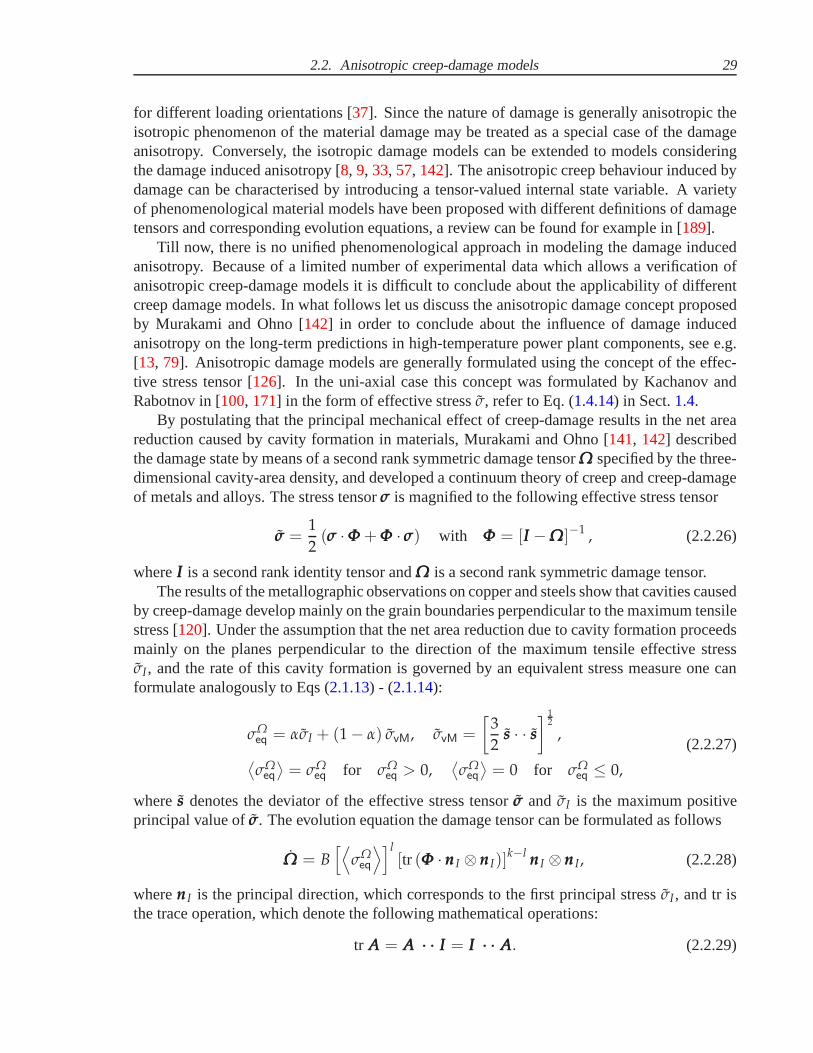
2.2. Anisotropic creep-damage models 29
for different loading orientations [37]. Since the nature of damage is generally anisotropic theisotropic phenomenon of the material damage may be treated as a special case of the damageanisotropy. Conversely, the isotropic damage models can beextended to models consideringthe damage induced anisotropy [8, 9, 33, 57, 142]. The anisotropic creep behaviour induced bydamage can be characterised by introducing a tensor-valuedinternal state variable. A varietyof phenomenological material models have been proposed with different definitions of damagetensors and corresponding evolution equations, a review can be found for example in [189].
Till now, there is no unified phenomenological approach in modeling the damage inducedanisotropy. Because of a limited number of experimental data which allows a verification ofanisotropic creep-damage models it is difficult to concludeabout the applicability of differentcreep damage models. In what follows let us discuss the anisotropic damage concept proposedby Murakami and Ohno [142] in order to conclude about the influence of damage inducedanisotropy on the long-term predictions in high-temperature power plant components, see e.g.[13, 79]. Anisotropic damage models are generally formulated using the concept of the effec-tive stress tensor [126]. In the uni-axial case this concept was formulated by Kachanov andRabotnov in [100, 171] in the form of effective stressσ, refer to Eq. (1.4.14) in Sect.1.4.
By postulating that the principal mechanical effect of creep-damage results in the net areareduction caused by cavity formation in materials, Murakami and Ohno [141, 142] describedthe damage state by means of a second rank symmetric damage tensorΩΩΩ specified by the three-dimensional cavity-area density, and developed a continuum theory of creep and creep-damageof metals and alloys. The stress tensorσσσ is magnified to the following effective stress tensor
σσσ =1
2(σσσ ·ΦΦΦ + ΦΦΦ · σσσ) with ΦΦΦ = [III −ΩΩΩ]−1 , (2.2.26)
whereIII is a second rank identity tensor andΩΩΩ is a second rank symmetric damage tensor.The results of the metallographic observations on copper and steels show that cavities caused
by creep-damage develop mainly on the grain boundaries perpendicular to the maximum tensilestress [120]. Under the assumption that the net area reduction due to cavity formation proceedsmainly on the planes perpendicular to the direction of the maximum tensile effective stressσI, and the rate of this cavity formation is governed by an equivalent stress measure one canformulate analogously to Eqs (2.1.13) - (2.1.14):
σΩeq = ασI + (1 − α) σvM, σvM =
[
3
2sss · · sss
]12
,
⟨
σΩeq
⟩
= σΩeq for σΩ
eq > 0,⟨
σΩeq
⟩
= 0 for σΩeq ≤ 0,
(2.2.27)
wheresss denotes the deviator of the effective stress tensorσσσ and σI is the maximum positiveprincipal value ofσσσ. The evolution equation the damage tensor can be formulatedas follows
ΩΩΩ = B[⟨
σΩeq
⟩]l[tr (ΦΦΦ · nnnI ⊗ nnnI)]
k−l nnnI ⊗ nnnI, (2.2.28)
wherennnI is the principal direction, which corresponds to the first principal stressσI, and tr isthe trace operation, which denote the following mathematical operations:
tr AAA = AAA ··· ··· III = III ··· ··· AAA. (2.2.29)
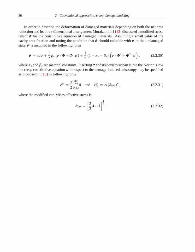
30 2. Conventional approach to creep-damage modeling
In order to describe the deformation of damaged materials depending on both the net areareduction and its three-dimensional arrangement Murakamiin [142] discussed a modified stresstensorσσσ for the constitutive equation of damaged materials. Assuming a small value of thecavity area fraction and noting the condition thatσσσ should coincide withσσσ in the undamagedstate,σσσ is assumed in the following form
σσσ = αs σσσ +1
2βs (σσσ ·ΦΦΦ + ΦΦΦ · σσσ) +
1
2(1 − αs − βs)
(
σσσ ·ΦΦΦ2 + ΦΦΦ2 · σσσ)
, (2.2.30)
whereαs andβs are material constants. Insertingσσσ and its deviatoric partsss into the Norton’s lawthe creep constitutive equation with respect to the damage-induced anisotropy may be specifiedas proposed in [13] in following form
εεεcr =3
2
εcreqσvM
sss and εcreq = A (σvM)n , (2.2.31)
where the modified von Mises effective stress is
σvM =
[
3
2sss · · sss
]12
. (2.2.32)

3. NON-ISOTHERMAL CREEP-DAMAGE MODEL FOR A WIDESTRESS RANGE
Many materials exhibit a stress range dependent creep behavior. The power-law creep observedfor a certain stress range changes to the viscous type creep if the stress value decreases. Recentlypublished creep experimental data for advanced heat resistant steels indicate that the high creepexponent (in the range 5-12 for power-law behaviour) may gradually decrease to the low valueof approximately 1 within the stress range relevant for engineering structures. The first aimof work presented in Sect.3.1 is to confirm the assumption, that the creep behavior is stressrange dependent demonstrating the power-law to viscous transition with a decreasing stress.The assumption is based on the available creep and stress relaxation experiments for the several9-12%Cr heat-resistant steels. An extended constitutive model for the minimum creep rate isintroduced to consider both the linear and the power law creep ranges depending upon the stresslevel. To take into account the primary creep behavior a strain hardening function is utilized.The data for the minimum creep rate is well-defined only for moderate and high stress levels. Toreconstruct creep rates for the low stress range the data of the stress relaxation test are applied,as presented in Sect.3.2 The results show a gradual decrease of the creep exponent with thedecrease stress level. Furthermore, they illustrate that the proposed constitutive model withstrain hardening function well describes the creep rates for a wide stress range including theloading values relevant to engineering applications. The proposed creep constitutive model isextended with the temperature dependence using the Arrhenius-type functions.
To characterize the tertiary creep behaviour and fracture the proposed constitutive equa-tion is generalized by introduction of damage internal state variables and appropriate evolutionequations. The description of long-term strength behaviour for advanced heat-resistant steelsis based on the assumption of ductile to brittle damage character transition with a decrease ofstress. The second aim of work presented in Sect.3.3 is to formulate the long-term strengthequation based on ductile to brittle damage transition and to confirm it with the available creep-rupture experiments for the 9-12%Cr advanced heat-resistant steels. Therefore, two damageparameters were introduced with ductile and brittle damageaccumulation characters. They arebased on the same long-term strength equation describing time-to-rupture, but lead to the dif-ferent types of fracture. Ductile fracture with progressive deformation and necking occurs athigh stress levels and is accompanied by power-low creep deformations. However, brittle frac-ture caused by thermal exposure and material microstructure degradation occurs at low stresslevels and it is dominantly accompanied by the linear creep deformations. And two correspond-ing ductile and brittle damage evolution equations based onKachanov-Rabotnov concept areformulated for the coupling with creep constitutive equation. The proposed damage evolutionequations are extended with the temperature dependence using the Arrhenius-type functions.All the necessary tertiary creep material parameters identified fitting the available from litera-
32 3. Non-isothermal creep-damage model for a wide stress range
ture creep-rupture experimental data for the 9-12%Cr advanced heat-resistant steels at severaltemperatures.
Finally in Sect.3.4 the unified multi-axial form of non-isothermal creep-damage model fora wide stress is proposed. The available creep-rupture experiments for 9-12%Cr heat-resistantsteels [155] suggests that the brittle damage evolution is primarily controlled by the maximumtensile stress at low stress levels. And within the range of high stresses the primarily ductilecreep damage is governed by the von Mises effective stress and leads to the necking of uniaxialspecimen. To analyse the failure mechanisms under multi-axial stress states the isochronousrupture loci (plots of stress states leading to the same timeto fracture) and time-to-rupture sur-face are presented. They illustrate that the proposed failure criterion include both the maximumtensile stress and the von Mises effective stress, as in the Sdobyrev [180] and Leckie-Hayhurstcriteria [86]. But the measures of influence of the both stress parametersare dependent on thelevel of stress showing ductile to brittle failure transition.
3.1 Non-isothermal creep constitutive modeling
Many components of power generation equipment and chemicalrefineries are subjected to hightemperature environments and complex loading over a long time. For such conditions the struc-tural behavior is governed by various time-dependent processes including creep deformation,stress relaxation, stress redistribution as well as damageevolution in the form of microcracks,microvoids, and other defects. The aim of “creep mechanics”is the development of methodsto predict time-dependent changes of stress and strain states in engineering structures up tothe critical stage of creep rupture, see e.g. [34, 152]. To this end various constitutive modelswhich reflect time-dependent creep deformations and processes accompanying creep like hard-ening/recovery and damage have been recently developed. One feature of the creep constitutivemodeling is the response function of the applied stress which is usually calibrated against theexperimental data for the minimum (secondary) creep rate. An example is the Norton-Baileylaw (power law) which is often applied because of easier identification of material constants,mathematical convenience in solving structural mechanicsproblems and possibility to analyzeextreme cases of linear creep or perfect plasticity by setting the creep exponent to unity or toinfinity, respectively. Therefore, the majority of available solutions within the creep structuralmechanics are based on the power law creep assumption, e.g. [34, 40, 94, 166].
On the other hand, it is known from the materials science thatthe “power law creep mecha-nism” operates only for a specific stress range and may changeto the linear, e.g. diffusion typemechanism with a decrease of the stress level [71]. As the recently published experimental datashow [108, 110, 117, 176, 177], advanced heat resistant steels exhibit the transition from thepower law to the linear creep at the stress levels relevant for engineering applications. To es-tablish creep behavior for low and moderate stress levels special experimental techniques wereemployed. Furthermore, experimental analysis of creep under low stress values requires expen-sive long-time tests. Although the results presented in [108, 110, 117, 176, 177] indicate thatthe power law may essentially underestimate the creep rate,experimental data for many othermaterials is not available, and the power law stress function is usually preferred.
Generally, the ranges of “low” and “moderate” stresses are specific for many engineering
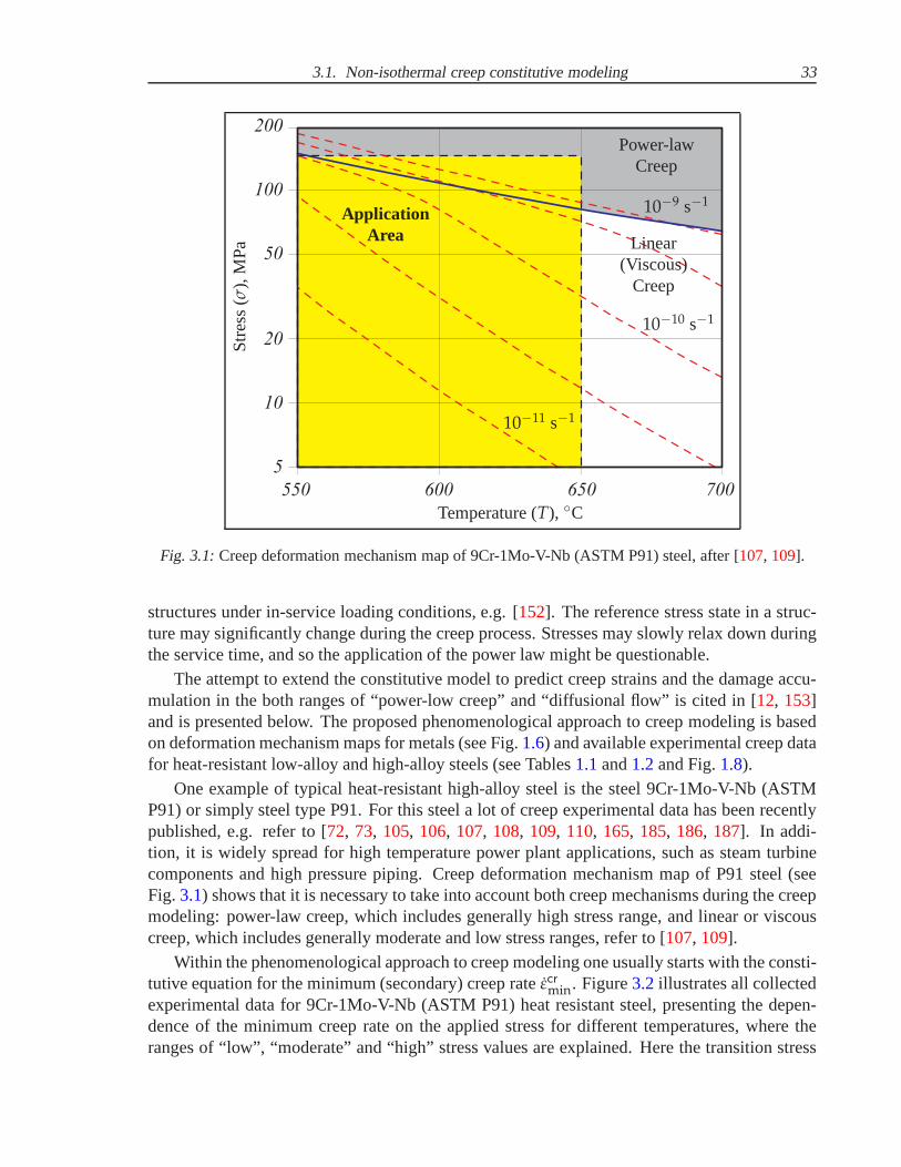
3.1. Non-isothermal creep constitutive modeling 33
550 600 650 700
200
100
50
20
10
5
Temperature (T), C
Str
ess
(σ),
MP
a
Power-lawCreep
ApplicationArea Linear
(Viscous)Creep
10−9 s−1
10−10 s−1
10−11 s−1
Fig. 3.1:Creep deformation mechanism map of 9Cr-1Mo-V-Nb (ASTM P91)steel, after [107, 109].
structures under in-service loading conditions, e.g. [152]. The reference stress state in a struc-ture may significantly change during the creep process. Stresses may slowly relax down duringthe service time, and so the application of the power law might be questionable.
The attempt to extend the constitutive model to predict creep strains and the damage accu-mulation in the both ranges of “power-low creep” and “diffusional flow” is cited in [12, 153]and is presented below. The proposed phenomenological approach to creep modeling is basedon deformation mechanism maps for metals (see Fig.1.6) and available experimental creep datafor heat-resistant low-alloy and high-alloy steels (see Tables1.1and1.2and Fig.1.8).
One example of typical heat-resistant high-alloy steel is the steel 9Cr-1Mo-V-Nb (ASTMP91) or simply steel type P91. For this steel a lot of creep experimental data has been recentlypublished, e.g. refer to [72, 73, 105, 106, 107, 108, 109, 110, 165, 185, 186, 187]. In addi-tion, it is widely spread for high temperature power plant applications, such as steam turbinecomponents and high pressure piping. Creep deformation mechanism map of P91 steel (seeFig. 3.1) shows that it is necessary to take into account both creep mechanisms during the creepmodeling: power-law creep, which includes generally high stress range, and linear or viscouscreep, which includes generally moderate and low stress ranges, refer to [107, 109].
Within the phenomenological approach to creep modeling oneusually starts with the consti-tutive equation for the minimum (secondary) creep rateεcrmin. Figure3.2illustrates all collectedexperimental data for 9Cr-1Mo-V-Nb (ASTM P91) heat resistant steel, presenting the depen-dence of the minimum creep rate on the applied stress for different temperatures, where theranges of “low”, “moderate” and “high” stress values are explained. Here the transition stress

34 3. Non-isothermal creep-damage model for a wide stress range
10-9
10-8
10-7
10-6
10-5
10-4
10-3
10-2
10-1
1
10
12
1
1
1
1 10 100 1000Stress (σ), MPa
Min
imu
mcr
eep
rate
(εcr min
),1
/hApplication rangeLow Moderate High
Experiments at 600C, after [107, 108, 187]Experiments at 625C, after [72, 73, 107]Experiments at 650C, after [106, 107]Transition from viscous creepto power-law creep mechanism
Fig. 3.2:Dependence of minimum creep strain rateεcrmin on stressσ for 9Cr-1Mo-V-Nb (ASTM P91)heat-resistant steel derived from the experiments after [72, 73, 106, 107, 108, 187].
σ0 reflects the transition from linear (viscous) creep mechanism to power-law creep mechanism.
We have decided to concentrate our investigations on temperature 600C as the most spreadin-service temperature among power plant components made of 9Cr-1Mo-V-Nb (ASTM P91)heat resistant steel, see Fig.3.3. Within the “low” stress range the creep rate is nearly linearfunction of stress, which corresponds to viscous creep character. The “moderate” stress rangeis characterized by the transition from linear to power law dependence. Within the region of“high” stresses the value of the creep exponent is usually inthe range between 4 and 12 de-pending on the material, type of alloying and processing conditions. The experimental data for9Cr-1Mo-V-Nb (ASTM P91) heat resistant steel show that the high stress range creep exponenttakes the value 12.
At first, the hyperbolic sine (Sinh) stress response function was tried as a basis of the consti-tutive model suitable for complete stress range, see Fig.3.3. It fits satisfactory experimental datafor the “low” and “high” stress ranges, but not suitable for “moderate” stress range. Therefore,the so-called double power-law stress response function proposed in [107] has been selectedas a basis. Relying on the assumptions of stress-dependent transition of creep-deformationmechanism from [107], Sect.1.3of the thesis and Norton-Bailey [27, 157] equation (1.3.9) thefollowing creep constitutive equation for a fixed temperature and wide stress range is proposed

3.1. Non-isothermal creep constitutive modeling 35
10-9
10-8
10-7
10-6
10-5
10-4
10-3
10-2
10-1
1
10
1 10 100 1000
1
1
12
1
Stress (σ), MPa
Min
imu
mcr
eep
rate
(εcr min
),1
/h
Application range
Low Moderate High
σ0
experimental creep data, after [107, 108, 187]
εcr = A1σ, σ ≤ σ0, A1 = 2.5 ··· 10−9 [MPa−1/h]
εcr = A2σ12, σ > σ0, A2 = 2.5 ··· 10−31 [MPa−12/h]
εcr = M sinh(Nσ),M = 4.5 ··· 10−8 1/h, N = 0.05 MPa−1
εcr = A1σ
[
1 +
(
σ
σ0
)11]
, σ0 = 100 MPa
Fig. 3.3:Fitting of creep experimental data [107, 108, 187] of minimum creep strain rateεcr by differentconstitutive equations for 9Cr-1Mo-V-Nb (ASTM P91) heat-resistant steel at 600C.
εcr = εcrv + εcrpl = A1 σ + A2 σn, (3.1.1)
whereεcr is the steady-state creep rate,εcrv is the rate of viscous mechanism,εcrpl is the rate ofpower-law mechanism andA1, A2 and the stress exponentn are secondary creep material pa-rameters. Otherwise, the proposed isothermal creep constitutive model presented by Eq. (3.1.1)can be transformed to the normalized form, which is more suitable for the creep material pa-rameters identification (for the detailed description refer to [12, 17, 78, 153]):
εcr = A σ
[
1 +
(
σ
σ0
)n−1]
, (3.1.2)
whereσ0 is the transition stress, presenting the transition from power-law creep behaviour tolinear. The required material parameters of the 9Cr-1Mo-V-Nb (ASTM P91) heat-resistantsteel for the creep constitutive model (3.1.2) are the following:A = A1 = 2.5 ··· 10−9 [MPa−1/h],n = 12, σ0 = 100 MPa. They are easily defined from separate fitting of experimental data for“low” and “high” stress ranges. The proposed creep constitutive equation (3.1.2) reflects thetransition from viscous to power-law creep mechanism and provides a good fitting of availableexperimental data [107, 108, 187] for the complete stress range, as illustrated on Fig.3.3.

36 3. Non-isothermal creep-damage model for a wide stress range
And the connection between the equivalent forms of creep constitutive equation presentedby Eqs (3.1.1) and (3.1.2) is following
A2 =A
(σ0)n−1⇐⇒ σ0 =
(
A
A2
)1
n−1
. (3.1.3)
The creep constitutive equation (3.1.1) can be extended with temperature dependence as-suming temperature-dependent secondary creep material parametersA1(T) and A2(T) in thefollowing form
εcr = εcrv (T) + εcrpl(T) = A1(T) σ + A2(T) σn, (3.1.4)
where the temperature dependence is introduced by the Arrhenius-type functions (1.3.8) simi-larly to Eq. (1.3.11)
A1(T) = A01 exp
(
−Q1
R T
)
and A2(T) = A02 exp
(
−Q2
R T
)
, (3.1.5)
where the constantsA01, A02 and creep activation energiesQ1, Q2 present the secondary creepmaterial parameters to be identified, and the universal gas constantR = 8.31[J··· K−1 ··· mol−1].
The normalized form of the creep constitutive equation (3.1.2) can be also extended withtemperature dependence assuming temperature-dependent secondary creep material parameterA1(T) and transition stressσ0(T) in the following form
εcr = A1(T) σ
[
1 +
(
σ
σ0(T)
)n−1]
, (3.1.6)
where the connection between the equivalent forms of creep constitutive model expressed byEqs (3.1.4) and (3.1.6) gives the following form of temperature-dependent transition stress:
A2(T) =A1(T)
[σ0(T)]n−1⇐⇒ σ0(T) =
[
A1(T)
A2(T)
]1
n−1
. (3.1.7)
Therefore, the transition stressσ0 can be presented in simple temperature-dependent formusing Arrhenius-type function (1.3.8) as follows
σ0(T) = Aσ exp
(
−Qσ
R T
)
, (3.1.8)
where Aσ is the secondary creep material parameter andQσ is the activation energy of thetransition to be identified. Creep parameters for the temperature-dependent transition stressσ0(T) from Eq. (3.1.8) are connected with creep material parameters for linear regime (A01,Q1) and power-law regime (A02, n, Q2) from Eqs (3.1.4) and (3.1.5) in the following way
Aσ =
(
A01
A02
)1
n−1
and Qσ =Q1 − Q2
n − 1. (3.1.9)
Finally, the experimental data [72, 73, 106, 107, 108, 187] presenting minimum creep rateεcrmin vs. stressσ for 9Cr-1Mo-V-Nb (ASTM P91) heat-resistant steel at temperatures 600C,

3.2. Stress relaxation problem and primary creep modeling 37
1 10 100 1000
10-9
10-8
10-7
10-6
10-5
10-4
10-3
10-2
10-1
1
10
1
1
12
1
Stress (σ), MPa
Min
imu
mcr
eep
rate
(εcr min
),1
/h
Application range
Low Moderate High
Experiments at 600C, after [107, 108, 187]Experiments at 625C, after [72, 73, 107]Experiments at 650C, after [106, 107]Transition from viscous creepto power-law creep mechanismCreep model at 600CCreep model at 625CCreep model at 650C
Fig. 3.4:Comparison of non-isothermal creep constitutive model (3.1.6) with experiments [72, 73, 106,107, 108, 187] for the 9Cr-1Mo-V-Nb (ASTM P91) steel at 600C, 625C and 650C.
625C and 650C is fitted with the creep constitutive equation (3.1.6). And as a result thefollowing secondary creep material parameters applicableto the wide stress and temperatureranges are identified:A01 = 2300 [MPa−1/h], Q1 = 200000 [J ··· mol−1], Aσ = 0.658 MPa,Qσ = 36364 [J··· mol−1] andn = 12.
The comparison of non-isothermal creep constitutive model(3.1.6) with experimental dataafter [72, 73, 106, 107, 108, 187] for 9Cr-1Mo-V-Nb (ASTM P91) heat-resistant steel at tem-peratures 600C, 625C and 650C shows a good correlation, as illustrated on Fig.3.4.
3.2 Stress relaxation problem and primary creep modeling
In structural analysis applications it is often desirable to consider stress redistributions fromthe beginning of the creep process up to the creep with constant rate. Let us note, that ina statically undetermined structure stress redistributions take place even if primary creep isignored. Although, the creep modeling with consideration of primary creep are important inmany applications of structural analysis when loading is inthe ranges of moderate and lowstress levels, which are relevant for engineering structures. The examples are stress relaxationand creep analysis for a wide stress range [17, 67, 78], multi-axial creep of thin-walled tubes

38 3. Non-isothermal creep-damage model for a wide stress range
under combined action of tension (compression) force and torque [152], analysis of the primarycreep behaviour of thin-walled shells subjected to internal pressure [35], the creep buckling ofcylindrical shells subjected to internal pressure and axial compression [36], etc.
The aim of this Section is to confirm the stress range dependence of creep behavior basedon the experimental data of stress relaxation. An extended constitutive model for the minimumcreep rate is introduced to consider both the linear and the power law creep ranges. To takeinto account the primary creep behavior a strain hardening function is utilized. The materialconstants are identified basing on the published experimental data of creep and stress relaxationfor a 9-12%Cr advanced heat-resistant steels [67, 163, 164]. The data for the minimum creeprate is well-defined only for moderate and high stress levels. To reconstruct creep rates for thelow stress range the data of the stress relaxation test are applied. The results show a gradualdecrease of the creep exponent with the decrease stress level. Furthermore, they illustrate thatthe proposed constitutive model well describes the creep rates for a wide stress range.
3.2.1 Stress relaxation problem
Primary and secondary creep behaviour of modern heat-resistant steels can be analysed usingthe available stress relaxation curves obtained from uniaxial experiments under the high temper-ature conditions, see e.g. [67], as shown below. Stress relaxation and creep experimentaldatafor the 12Cr-1Mo-1W-0.25V steel bolting material at 500C presented in [163, 164] has beenselected for the formulation of the constitutive creep model for a wide stress range. Figure3.5illustrates the typical stress relaxation curves of the 12Cr-1Mo-1W-0.25V steel at 500C ob-tained during the experiments [163]. The uniaxial constitutive model presented below is validfor primary and secondary creep stages and includes the creep material parameters identifiedfrom the available stress relaxation and creep experimental data.
Experimental relaxation curves [163] can be transformed into creep strain vs. time depen-dence (see Fig.3.6) as follows:
εcr(t) =σini − σ(t)
E, (3.2.10)
whereεcr(t) denotes the creep strain,σini is the initial stress in the test,σ(t) is the residual stress(the experimental values ofσini and σ(t) are given in [163]), E = 164.8 GPa is the Young’smodulus of the 12Cr-1Mo-1W-0.25V steel at 500C from [192].
The experimental dependencies presenting residual stressvs. time and creep strain vs. timecan be combined into a general 3D plot with the timet, the residual stressσ and the creep strainεcr as orthogonal axes containing relaxation trajectories corresponding to the defined values ofthe constant total strainεtot = 0.25%, 0.20%, 0.15%, 0.10%, as illustrated on Fig.3.7. Thesetrajectories are formed by the interpolation of experimental points withεcr(t), σ(t) and t ascoordinates into solid lines in the CAD-software SolidWorks.
The relaxation experimental data for 12Cr-1Mo-1W-0.25V steel bolting material at 500Cin the form of 3D trajectories presenting creep strainεcr vs. residual stressσ and timet is fittedwith the 3D surface by the way of kriging correlation gridding in the mathematical softwareOriginPro, as illustrated on Fig.3.8.
But the 3D surface obtained by the kriging correlation gridding does not fit precisely the re-laxation experimental data for 12Cr-1Mo-1W-0.25V steel bolting material at 500C after [163].

3.2. Stress relaxation problem and primary creep modeling 39
50
100
150
200
250
300
350
400
0.1 1 10 100 1000 10000
Time (t), h
Res
idu
alst
ress
(σ),
MP
aTotal strain:
0.25%0.20%0.15%0.10%
Fig. 3.5:Stress relaxation experimental data for the 12Cr-1Mo-1W-0.25V steel at 500C, after [163].
0
0.0002
0.0004
0.0006
0.0008
0.001
0.0012
0.0014
0.0016
0.1 1 10 100 1000 10000
Total strain:0.25%0.20%0.15%0.10%
Time (t), h
Cre
epst
rain
(εcr )
Fig. 3.6:Creep strains calculated from the relaxation data for the 12Cr-1Mo-1W-0.25V steel boltingmaterial at temperature 500C, after [163].
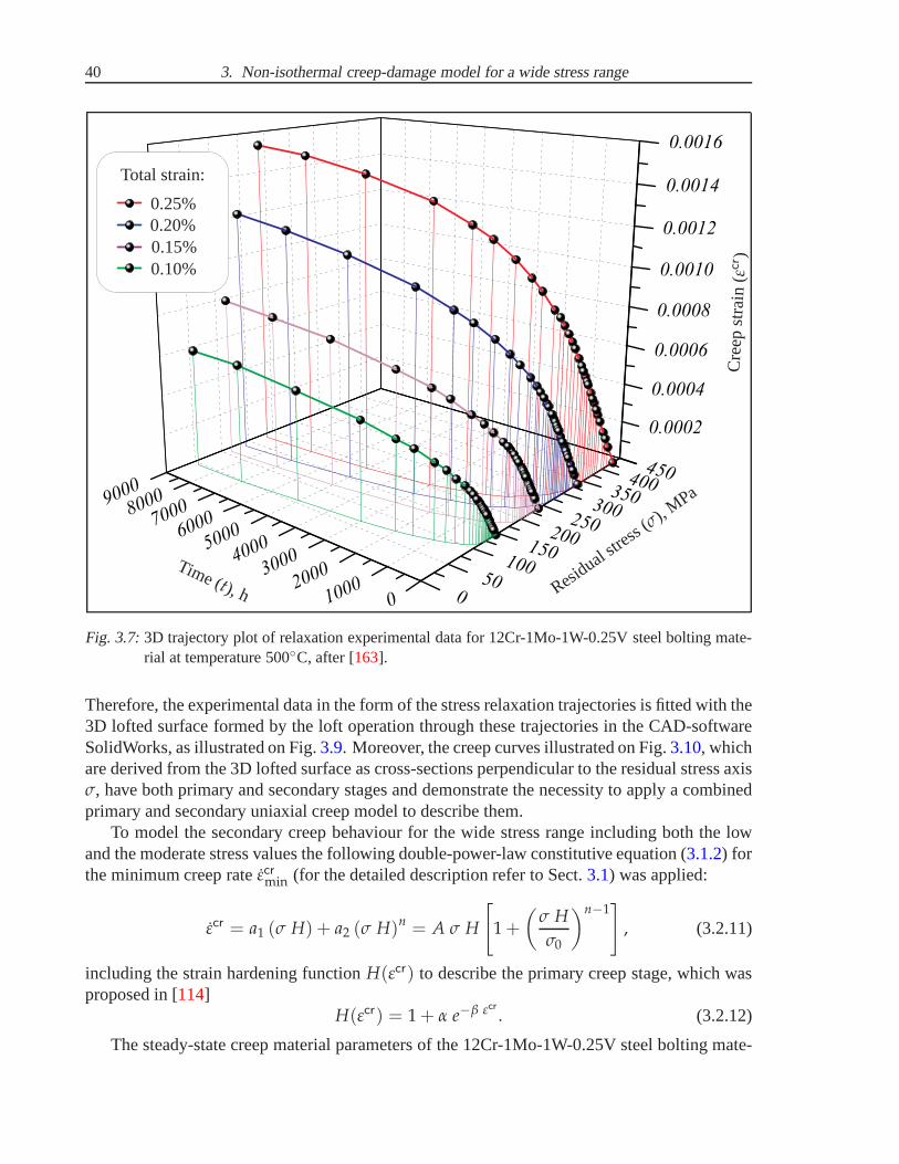
40 3. Non-isothermal creep-damage model for a wide stress range
0
50
100
150
200
250
300
350
400
0100020003000400050006000700080009000
0.0002
0.0004
0.0006
0.0008
0.0010
0.0012
0.0014
0.0016
450
Time (t), h Residual st
ress(σ), MPa
Cre
epst
rain
(εcr )
Total strain:
0.25%0.20%0.15%0.10%
Fig. 3.7:3D trajectory plot of relaxation experimental data for 12Cr-1Mo-1W-0.25V steel bolting mate-rial at temperature 500C, after [163].
Therefore, the experimental data in the form of the stress relaxation trajectories is fitted with the3D lofted surface formed by the loft operation through thesetrajectories in the CAD-softwareSolidWorks, as illustrated on Fig.3.9. Moreover, the creep curves illustrated on Fig.3.10, whichare derived from the 3D lofted surface as cross-sections perpendicular to the residual stress axisσ, have both primary and secondary stages and demonstrate thenecessity to apply a combinedprimary and secondary uniaxial creep model to describe them.
To model the secondary creep behaviour for the wide stress range including both the lowand the moderate stress values the following double-power-law constitutive equation (3.1.2) forthe minimum creep rateεcrmin (for the detailed description refer to Sect.3.1) was applied:
εcr = a1 (σ H) + a2 (σ H)n = A σ H
[
1 +
(
σ H
σ0
)n−1]
, (3.2.11)
including the strain hardening functionH(εcr) to describe the primary creep stage, which wasproposed in [114]
H(εcr) = 1 + α e−β εcr . (3.2.12)
The steady-state creep material parameters of the 12Cr-1Mo-1W-0.25V steel bolting mate-
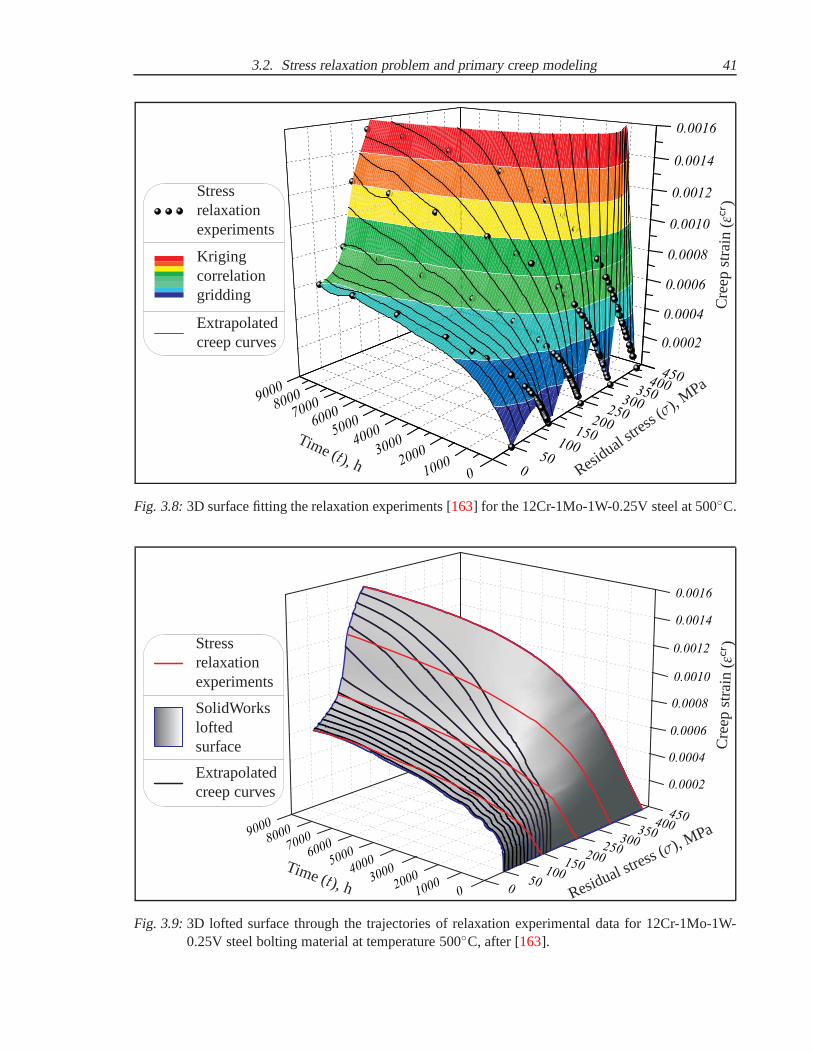
3.2. Stress relaxation problem and primary creep modeling 41
0
50
100
150
200
250
300
350
400450
0100020003000400050006000700080009000
0 0002.
0 0004.
0 0006.
0 0008.
0 0010.
0 0012.
0 0014.
0 0016.
Time (t), h Residual s
tress
(σ), MPa
Cre
epst
rain
(εcr )
Stressrelaxationexperiments
Krigingcorrelationgridding
Extrapolatedcreep curves
Fig. 3.8:3D surface fitting the relaxation experiments [163] for the 12Cr-1Mo-1W-0.25V steel at 500C.
050
100
150200
250300
350400
450
0100020003000400050006000700080009000
0 0002.
0 0004.
0 0006.
0 0008.
0 0010.
0 0012.
0 0014.
0 0016.
Time (t), h Residual stress (σ), MPa
Cre
epst
rain
(εcr )Stress
relaxationexperiments
SolidWorksloftedsurface
Extrapolatedcreep curves
Fig. 3.9:3D lofted surface through the trajectories of relaxation experimental data for 12Cr-1Mo-1W-0.25V steel bolting material at temperature 500C, after [163].
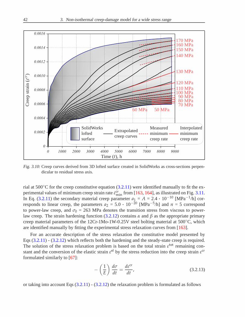
42 3. Non-isothermal creep-damage model for a wide stress range
0.0016
0.0014
0.0012
0.0010
0.0008
0.0006
0.0004
0.0002
0
0 1000 2000 3000 4000 5000 6000 7000 8000 9000
Time (t), h
Cre
epst
rain
(εcr)
170 MPa160 MPa150 MPa140 MPa
130 MPa
120 MPa110 MPa100 MPa90 MPa80 MPa70 MPa
60 MPa 50 MPa
SolidWorksloftedsurface
Extrapolatedcreep curves
Measuredminimumcreep rate
Interpolatedminimumcreep rate
Fig. 3.10:Creep curves derived from 3D lofted surface created in SolidWorks as cross-sections perpen-dicular to residual stress axis.
rial at 500C for the creep constitutive equation (3.2.11) were identified manually to fit the ex-perimental values of minimum creep strain rateεcrmin from [163, 164], as illustrated on Fig.3.11.In Eq. (3.2.11) the secondary material creep parametera1 = A = 2.4 ··· 10−10 [MPa−1/h] cor-responds to linear creep, the parametersa2 = 5.0 ··· 10−20 [MPa−5/h] and n = 5 correspondto power-law creep, andσ0 = 263 MPa denotes the transition stress from viscous to power-law creep. The strain hardening function (3.2.12) containsα andβ as the appropriate primarycreep material parameters of the 12Cr-1Mo-1W-0.25V steel bolting material at 500C, whichare identified manually by fitting the experimental stress relaxation curves from [163].
For an accurate description of the stress relaxation the constitutive model presented byEqs (3.2.11) - (3.2.12) which reflects both the hardening and the steady-state creep is required.The solution of the stress relaxation problem is based on thetotal strainεtot remaining con-stant and the conversion of the elastic strainεel by the stress reduction into the creep strainεcr
formulated similarly to [67]:
−
(
1
E
)
dσ
dt=
dεcr
dt, (3.2.13)
or taking into account Eqs (3.2.11) - (3.2.12) the relaxation problem is formulated as follows
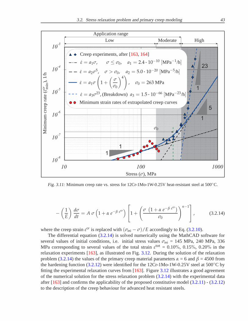
3.2. Stress relaxation problem and primary creep modeling 43
1
1
5
1
23
1
10 100 1000
10
10
10
10
10
10
-3
-4
-5
-6
-7
-8
Stress (σ), MPa
Min
imu
mcr
eep
rate
(εcr min
),1
/h
Application rangeLow Moderate High
σ0
Creep experiments, after [163, 164]
ε = a1σ, σ ≤ σ0, a1 = 2.4 ··· 10−10 [MPa−1/h]
ε = a2σ5, σ > σ0, a2 = 5.0 ··· 10−20 [MPa−5/h]
ε = a3σ23, (Breakdown)a3 = 1.5 ··· 10−66 [MPa−23/h]
Minimum strain rates of extrapolated creep curves
ε = a1σ
(
1 +
(
σ
σ0
)4)
, σ0 = 263 MPa
Fig. 3.11:Minimum creep rate vs. stress for 12Cr-1Mo-1W-0.25V heat-resistant steel at 500C.
−
(
1
E
)
dσ
dt= A σ
(
1 + α e−β εcr)
1 +
(
σ(
1 + α e−β εcr)
σ0
)n−1
, (3.2.14)
where the creep strainεcr is replaced with(σini − σ)/E accordingly to Eq. (3.2.10).The differential equation (3.2.14) is solved numerically using the MathCAD software for
several values of initial conditions, i.e. initial stress valuesσini = 145 MPa, 240 MPa, 336MPa corresponding to several values of the total strainεtot = 0.10%, 0.15%, 0.20% in therelaxation experiments [163], as illustrated on Fig.3.12. During the solution of the relaxationproblem (3.2.14) the values of the primary creep material parametersα = 6 andβ = 4500 fromthe hardening function (3.2.12) were identified for the 12Cr-1Mo-1W-0.25V steel at 500C byfitting the experimental relaxation curves from [163]. Figure3.12illustrates a good agreementof the numerical solution for the stress relaxation problem(3.2.14) with the experimental dataafter [163] and confirms the applicability of the proposed constitutive model (3.2.11) - (3.2.12)to the description of the creep behaviour for advanced heat resistant steels.
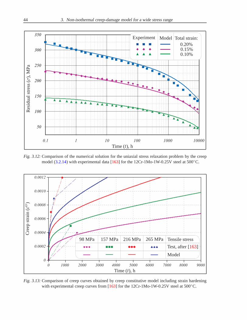
44 3. Non-isothermal creep-damage model for a wide stress range
50
100
150
200
250
300
350
0.1 1 10 100 1000 10000
Time (t), h
Res
idu
alst
ress
(σ),
MP
a
Experiment Model Total strain:0.20%0.15%0.10%
Fig. 3.12:Comparison of the numerical solution for the uniaxial stress relaxation problem by the creepmodel (3.2.14) with experimental data [163] for the 12Cr-1Mo-1W-0.25V steel at 500C.
0.0012
0.0010
0.0008
0.0006
0.0004
0.0002
0
0 1000 2000 3000 4000 5000 6000 7000 8000 9000
Time (t), h
Cre
epst
rain
(εcr )
98 MPa 157 MPa 216 MPa 265 MPa
Test, after [163]
Model
Tensile stress
Fig. 3.13:Comparison of creep curves obtained by creep constitutive model including strain hardeningwith experimental creep curves from [163] for the 12Cr-1Mo-1W-0.25V steel at 500C.
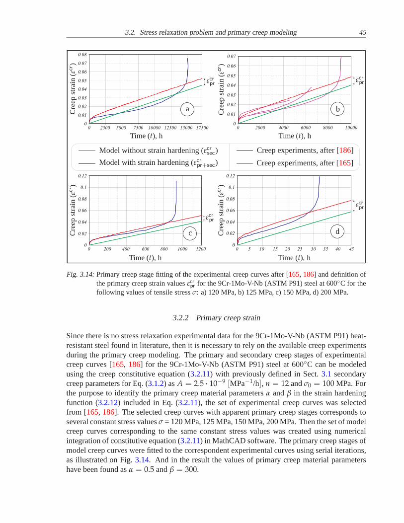
3.2. Stress relaxation problem and primary creep modeling 45
0
0 02.
0 04.
0 06.
0 08.
0 2500 5000 7500 10000 12500 15000 17500
0 0. 7
0 0. 5
0 0. 3
0 0. 1
0
0 02.
0 04.
0 06.
0 0. 7
0 2000 4000 6000 8000 10000
0 0. 5
0 0. 3
0 0. 1
0
0 02.
0 0. 4
0 0. 8
0 1.
0 200 400 600 800 1000 1200
0 0. 6
0 1. 2
0
0 02.
0 0. 6
0 0. 8
0 1.
0 12.
0 5 10 15 20 25 30 35 40 45
0 0. 4
a b
c d
Time (t), hTime (t), h
Time (t), hTime (t), h
Cre
epst
rain
(εcr )
Cre
epst
rain
(εcr )
Cre
epst
rain
(εcr )
Cre
epst
rain
(εcr )
Creep experiments, after [186]
Creep experiments, after [165]
Model without strain hardening (εcrsec)
Model with strain hardening (εcrpr+sec)
εcrpr
εcrpr
εcrprεcrpr
Fig. 3.14:Primary creep stage fitting of the experimental creep curvesafter [165, 186] and definition ofthe primary creep strain valuesεcrpr for the 9Cr-1Mo-V-Nb (ASTM P91) steel at 600C for thefollowing values of tensile stressσ: a) 120 MPa, b) 125 MPa, c) 150 MPa, d) 200 MPa.
3.2.2 Primary creep strain
Since there is no stress relaxation experimental data for the 9Cr-1Mo-V-Nb (ASTM P91) heat-resistant steel found in literature, then it is necessary torely on the available creep experimentsduring the primary creep modeling. The primary and secondary creep stages of experimentalcreep curves [165, 186] for the 9Cr-1Mo-V-Nb (ASTM P91) steel at 600C can be modeledusing the creep constitutive equation (3.2.11) with previously defined in Sect.3.1 secondarycreep parameters for Eq. (3.1.2) asA = 2.5 ··· 10−9 [MPa−1/h], n = 12 andσ0 = 100 MPa. Forthe purpose to identify the primary creep material parameters α andβ in the strain hardeningfunction (3.2.12) included in Eq. (3.2.11), the set of experimental creep curves was selectedfrom [165, 186]. The selected creep curves with apparent primary creep stages corresponds toseveral constant stress valuesσ = 120 MPa, 125 MPa, 150 MPa, 200 MPa. Then the set of modelcreep curves corresponding to the same constant stress values was created using numericalintegration of constitutive equation (3.2.11) in MathCAD software. The primary creep stages ofmodel creep curves were fitted to the correspondent experimental curves using serial iterations,as illustrated on Fig.3.14. And in the result the values of primary creep material parametershave been found asα = 0.5 andβ = 300.

46 3. Non-isothermal creep-damage model for a wide stress range
The next step was the creation of the set of model creep curveswithout primary creep stageusing constitutive equation (3.1.2) for the same constant stress values as before, see Fig.3.14.Consequently, the creep strain accumulated during the primary stageεcrpr is calculated as thepositive difference between the creep strainεcrpr+sec accumulated with strain hardening effect byEq. (3.2.11) and the creep strainεcrsec accumulated without strain hardening effect by Eq. (3.1.2)in the following form:
εcrpr = εcrpr+sec(σ) − εcrsec(σ). (3.2.15)
It is necessary to notice, that the mathematical operation (3.2.15) was performed numeri-cally in MathCAD software for the whole stress range at 600C. The creep strain accumulatedduring the primary stageεcrpr was calculated for each value of stressσ on the moments of time,when the influence of the strain hardening function (3.2.12) on the creep curve was negligible,as illustrated on Fig.3.14.
Finally, the primary creep strainεcrpr vs. stressσ dependence, illustrated on Fig.3.15, can befitted using the Boltzmann function producing a sigmoidal curve
εcrpr(σ) = εcrpr max +εcrpr min − εcrpr max
1 + exp(
σ−σC
) , (3.2.16)
where the defined fitting parameters are following: the transition constantC = 9.5, transitionstressσ = 87 MPa corresponding to the mean value of primary creep strain εcr
pr = 4.56·10−3,primary creep strain value in the low stress rangeεcrpr min = 1.35·10−3, primary creep strain
value in the high stress rangeεcrpr max = 7.76·10−3.The primary creep strain function (3.2.16) will be taken into account in Sect.3.3during the
fitting of the experimental rupture creep strainε∗ vs. stressσ dependence by the Eq. (3.3.28)for the purpose of the tertiary creep material parameters identification.
3.3 Non-isothermal long-term strength and tertiary creep modeling
One of the approaches to long-term strength estimation of advanced heat-resistant steels is basedon the time-to-failure concept in the form proposed in [25, 122, 136, 195]. Since creep causescreep fracture, the time-to-failuret∗ is described by a constitutive equation which looks verylike that for creep itself, see e.g. Eq. (1.3.11)
t∗ = Bf σ−m exp
(
Qf
RT
)
, (3.3.17)
whereBf , m andQf are the creep-failure constants, determined in the same wayas those forcreep. The behavior oft∗ with respect toσ andT is similar to that ofεcr, with the differencesbeing that the signs are reversed for the stress exponentm and the activation energyQf , becauset∗ is a time whereasεcr is a rate, refer to [25, 195].
In many high-strength alloys this creep damage appears early in life and leads to failure aftersmall creep strains (approximately 1%). In high-temperature design of structures it is importantto make sure:
• that thecreep strainεcr during the design life is acceptable;

3.3. Non-isothermal long-term strength and tertiary creepmodeling 47
0
0.002
0.004
0.006
0.008
0 50 100 150 200 250 300
0.001
0.003
0.005
0.007
0.007
Stress (σ), MPa
Prim
ary
cree
pst
rain
(εcr pr)
Primary creep strain values
Primary creep strain function
εcrpr min
εcrpr max
Low stress High stressModerate stress
σ
εcrpr
Fig. 3.15:Stress dependence of primary creep strainεcrpr for the 9Cr-1Mo-V-Nb (ASTM P91) heat-resistant steel at 600C in the complete stress range.
• that thecreep ductilityε∗ (strain to failure) is adequate to cope with the acceptable creepstrain;
• that thetime-to-rupturet∗ at the design loadsσ and temperaturesT is longer (by a suitablesafety factor) than the design life.
Times-to-failure are normally presented ascreep-rupturediagrams orlong-term strengthcurves, as illustrated on Fig.3.16. Their application is obvious: if you know the stressσ and thetemperatureT you can read off the lifet∗; if you wish to design for a certain lifet∗ at a certaintemperatureT, you can read off the design stressσ.
Typical long-term strengthcurves for advanced heat-resistant steels (see e.g. Fig.3.16)demonstrate the transition from ductile damage character dominant in the “high” stress rangeto the brittle damage character dominant in the “low” stressrange, i.e. mixed damage modeduring the “moderate” stress range, see e.g. [25, 152, 166, 179]. The brittle damage characterdominant in the “low” stress range is caused the overaging and material microstructure degra-dation for the advanced heat-resistant steels. Thus, brittle damage character is accompanied bythe significant decreasing of thetime-to-rupturet∗, as was shown in experimental studies e.g.
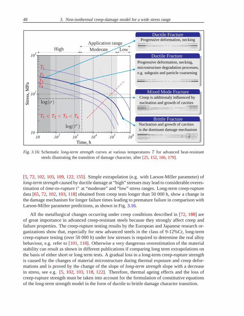
48 3. Non-isothermal creep-damage model for a wide stress range
210
10 103
104
105
106
10
210
310
Str
ess,
MP
a
Time, h
Ductile Fracture
Ductile Fracture
Progressive deformation, necking
Progressive deformation, necking,microstructure degradation processes,e.g. subgrain and particle coarsening
Mixed Mode FractureCreep is additionaly influenced bynucleation and growth of cavities
Brittle FractureNucleation and growth of cavitiesis the dominant damage mechanism
T1
T2
T3T4
T1 < T2 < T3 < T4
log(σ)
log(t∗)
Application rangeLowModerateHigh
Fig. 3.16:Schematiclong-term strengthcurves at various temperaturesT for advanced heat-resistantsteels illustrating the transition of damage character, after [25, 152, 166, 179].
[5, 72, 102, 103, 109, 122, 155]. Simple extrapolation (e.g. with Larson-Miller parameter) oflong-term strengthcaused by ductile damage at “high” stresses may lead to considerable overes-timation of time-to-rupturet∗ at “moderate” and “low” stress ranges. Long-term creep-rupturedata [65, 72, 102, 103, 118] obtained from creep tests longer than 50 000 h, show a changeinthe damage mechanism for longer failure times leading to premature failure in comparison withLarson-Miller parameter predictions, as shown in Fig.3.16.
All the metallurgical changes occurring under creep conditions described in [72, 188] areof great importance in advanced creep-resistant steels because they strongly affect creep andfailure properties. The creep-rupture testing results by the European and Japanese research or-ganizations show that, especially for new advanced steels in the class of 9-12%Cr, long-termcreep-rupture testing (over 50 000 h) under low stresses is required to determine the real alloybehaviour, e.g. refer to [101, 118]. Otherwise a very dangerous overestimation of the materialstability can result as shown in different publications if comparing long term extrapolations onthe basis of either short or long term tests. A gradual loss ina long-term creep-rupture strengthis caused by the changes of material microstructure during thermal exposure and creep defor-mations and is proved by the change of the slope oflong-term strengthslope with a decreasein stress, see e.g. [5, 102, 103, 118, 122]. Therefore, thermal ageing effects and the loss ofcreep-rupture strength must be taken into account for the formulation of constitutive equationsof the long-term strength model in the form of ductile to brittle damage character transition.

3.3. Non-isothermal long-term strength and tertiary creepmodeling 49
3.3.1 Stress dependence
An important problem of the creep-damage modeling is the ability to extrapolate the laboratorycreep-rupture data usually obtained under increased stressσ and temperatureT to the in-serviceloading conditions in “moderate” and “low” ranges of stressσ and temperatureT. The tertiarycreep parameters corresponding to “low” stress range can beidentified only from the extrapola-tion of long-term strengthcurve based on the assumptions of ductile to brittle damage charactertransition [166], and accelerated microstructure degradation [5, 102] during thermal exposureand creep deformations.
All the available experimental creep-rupture data from [44, 102, 107, 109, 118, 162,178, 186, 187] for the 9Cr-1Mo-V-Nb (ASTM P91) heat-resistant steel at 600C illustratedon Fig. 3.17 shows that only “high” and “moderate” stress ranges can be analysed bas-ing on experiments. Thereby, it is possible to formulate thepart of long-term strengthcurve fitting the “high” stress experimental creep-rupturedata and to identify the tertiarycreep parameters corresponding to ductile damage character. The formulation oflong-termstrengthequation for the complete stress range of the 9Cr-1Mo-V-Nb (ASTM P91) steel at600C begins with the “high” stress range. The available experimental creep-rupture data[44, 102, 107, 109, 118, 162, 178, 186, 187] is fitted by the Eq. (3.3.17) for “linear” long-termstrengthcurve at constant temperature 600C:
t∗ = b2 σ−(n−k), (3.3.18)
wheren = 12 is the power-law exponent from (3.1.2) for the 9Cr-1Mo-V-Nb (ASTM P91) steelat 600C, and the tertiary creep material parameterb2 for the “high” stress range is definedas b2 = 1.25 ··· 1028 [h · MPa(n−k)]. The value of tertiary material parameterk = 0.5 definesthe difference in power-law exponents between the minimum creep strain rateεcrmin vs. stressσ dependence and thelong-term strengthcurve in the complete stress range. And referringto [152] tertiary creep parameterk must have the value lying in range(0 < k < 1) for thecreep-damage models based on Kachanov-Rabotnov concept [89, 100, 171].
Unfortunately, there is no creep-rupture experimental data in the “low” stress range availablein literature for the 9Cr-1Mo-V-Nb (ASTM P91) steel at 600C. It is caused by the extremelylong duration of necessary creep tests which should be over 100 000 hours to achieve the criticalphase of creep rupture for low stress values less than 70 MPa.Visual observation of experi-mental creep-rupture data [44, 102, 107, 109, 118, 162, 178, 186, 187] for the 9Cr-1Mo-V-Nb(ASTM P91) steel at 600C shows that the approximate location of transition from “ductile”to “brittle” damage character can be detected in the “moderate” stress range. This transitionis visualized in the graduate change of slope of long-term strength curve with the reduction ofstressσ and is proved by the available creep-rupture experimental data in the “moderate” stressrange, as illustrated on Fig.3.17. Therefore, the expected location of the “linear”long-termstrengthcurve in “low” stress range can be estimated using the approximate value of the tran-sition stressσ0 from ductile to brittle damage character. Since the approximate value of thetransition stress is taken asσ0 = 100 MPa, than the equation for thelong-term strengthcurve atconstant temperature 600C is following:
t∗ = b1 σ−(1−k), (3.3.19)

50 3. Non-isothermal creep-damage model for a wide stress range
10
100
300
1 10 10 10 10 10 102 3 4 5 6
1
0.5
11.5
1
Time to rupture (t∗), h
Str
ess
(σ),
MP
a
Low
Mo
der
ate
Hig
h
Ap
plic
atio
nra
ng
e
σ0
Experimental creep-rupture data, after [44, 102, 107, 109, 162, 178, 186, 187]
t∗ = b2 σ−(n−k) with b2 = 1.25 ··· 1028 [h · MPa(n−k)],
t∗ = b1 σ−(1−k) with b1 = 1.25 ··· 106 [h · MPa(1−k)],
t∗ =
[
σ(1−k)
b1+
σ(n−k)
b2
]−1
=B
σ1−k σn−10 + σn−k
B = b2 = 1.25 ··· 1028 [h · MPa(n−k)], σ0 = 100 MPa
n = 12k = 0.5
Fig. 3.17:Experimental creep-rupture data [44, 102, 107, 109, 162, 178, 186, 187] for the 9Cr-1Mo-V-Nb (ASTM P91) steel at 600C fitted by the Eq. (3.3.20) for long-term strengthcurve.
where the tertiary creep material parameterb1 for the “low” stress range is identified asb1 = 1.25 ··· 106 [h ··· MPa(1−k)] by the manual fitting.
The value of stressσ0, which denotes the transition from ductile to brittle damage mecha-nism at 600C, have been taken the same as the stressσ0, which denotes transition from viscousto power-low creep at 600C in Eq. (3.1.2). But for other temperatures the values ofσ0 andσ0
may be rather different. Using the defined valueσ0 = 100 MPa it is possible to formulate thefollowing equation of thelong-term strengthcurve in the complete stress range with previouslyidentified tertiary creep material parameters:
t∗ =
(
σ1−k
b1+
σn−k
b2
)−1
=B
σ1−k σn−10 + σn−k
, (3.3.20)
where the tertiary creep material parameterB for the complete stress range is identified asB = b2 = 1.25 ··· 1028 [h ··· MPa(n−k)]. The long-term strengthcurve (3.3.20) illustrated onFig. 3.17 takes into account ductile damage mode for “high” stresses,brittle damage modefor “low” stresses and mixed damage mode for “moderate” stresses, defined by the transitionstress valueσ0 = 100 MPa.

3.3. Non-isothermal long-term strength and tertiary creepmodeling 51
1
0.8
0.6
0.4
0.2
0
Dam
age
par
amet
er(
ω)
ω(t) = 1 −
(
1 −t
t∗
)1
l+1
Time (t)
Time torupture(t∗)
(brittle) l = 15
(mixed)l = 7
(ductile)l = 3
Fig. 3.18:Classification of accumulation character types for the scalar damage parameterω usingEq. (3.3.21) according to Kachanov-Rabotnov concept [89, 100, 171].
3.3.2 Creep-damage coupling
The next step in the phenomenological approach to creep modeling is the formulation of damagemechanism incorporated into the creep constitutive model (3.1.2). To characterize the damageprocesses the creep constitutive equation (3.1.2) must be generalized by introduction of the dam-age internal state variables and appropriate evolution equations. Isotropic damage models aregenerally formulated using the the concepts of scalardamage parameterω using Eq. (1.4.13)and theeffective stressσ using Eq. (1.4.15) as described in Sect.1.4, see e.g. [34, 124, 152, 166].
In the frames of the developed creep-damage model it is necessary to introduce the damageparameterω which reflects both ductile and brittle damage characters. Due to the Kachanov-Rabotnov concept [100, 171] the value of damage parameterω lies in the range(0 ≤ ω ≤ 1),where theω = 0 corresponds to the undamaged state in the initial moment of time t andω = 1corresponds to fracture whent = t∗. The accumulation character of damage parameterω canbe analyzed using the following equation, as illustrated onFig. 3.18:
ω(t) = 1 −
(
1 −t
t∗
)1
l+1
, (3.3.21)
where the tertiary creep material constantl governs the accumulation character of damage pa-rameterω and defines the fracture ductilityε∗. The damage character can be approximatelyestimated using the values ofl considering the following criterion:l < 5 corresponds to ductiledamage mode,l > 15 corresponds to brittle damage mode, and(5 ≤ l ≤ 15) describes the“mixed” damage mode, as illustrated on Fig.3.18.
Creep-rupture observations for 9-12%Cr heat-resistant steels in [122] shows that
• “breakdown of creep strength” (rapid decrease of the slope of long-term strengthcurveand decrease of creep ductilityε∗) is connected with brittle damage mode,
• brittle damage mode is only dominant in the linear creep range under low stress level,
• ductile damage processes influence on the creep deformations in the power law creeprange.

52 3. Non-isothermal creep-damage model for a wide stress range
Therefore, by analogy to Kachanov-Rabotnov-Hayhurst creep-damage model [89, 100, 171]a new creep constitutive equation (3.2.11) based on double power-law stress response function(3.1.2) is formulated using thestrain equivalence principleafter Lemaitre [123] and ductile tobrittle damage character transition [122, 155] as follows
εcr = Aσ H
1 − ωb
+A
σn−10
(
σ H
1 − ωd
)n
, (3.3.22)
including the strain-hardening function (3.2.12) to describe the primary creep stage
H(εcr) = 1 + α exp(−β εcr). (3.3.23)
In notation (3.3.22) the values of secondary creep parameters defined in Eq. (3.1.2) for the 9Cr-1Mo-V-Nb heat-resistant steel at 600C are following:n = 12, A = 2.5 ··· 10−9 [MPa−1/h] andthe transition stressσ0 = 100 MPa. The variableωb denotes the brittle damage parameter andvariableωd denotes the ductile damage parameter. In notation (3.3.23) the values of primarycreep parameters defined in Sect.3.2.2for the 9Cr-1Mo-V-Nb (ASTM P91) heat-resistant steelat 600C are following:α = 0.5 andβ = 300.
Creep constitutive equation (3.3.22) must be accompanied with the damage evolution equa-tions. They were formulated for the brittleωb and ductileωd damage parameters similarly toKachanov-Rabotnov-Hayhurst creep-damage model [89, 100, 171] as follows
ωb =1
t∗ (l1 + 1) (1 − ωb)l1and ωd =
1
t∗ (l2 + 1) (1 − ωd)l2, (3.3.24)
wheret∗(σ) is the stress-dependent time-to-rupture function according to Eq. (3.3.20), and thetertiary creep material parameters for the 9Cr-1Mo-V-Nb (ASTM P91) heat-resistant steel at600C defined by Eq. (3.3.20) are the following:B = 1.25 ··· 1028 [h ··· MPa(n−k)], k = 0.5 andtransition stressσ0 = 100 MPa. In Eqs (3.3.20) and (3.3.24) the power-law exponentn = 12 istaken from the constitutive equation (3.3.22). The tertiary creep material parametersl1 govern-ing the brittle damage mode andl2 governing the ductile damage mode have to be defined fromthe experimental data for creep-fracture ductilityε∗.
Formulating the damage accumulation equation (3.3.21) for the brittle and ductile values ofcreep parameterl one can obtain the following mathematical conversion
(
1 −t
t∗
)
= (1 − ωb)l1+1 = (1 − ωd)
l2+1. (3.3.25)
Hereby, in the proposed creep-damage model (3.3.22) - (3.3.24) only the one damage evolutionequation can be formulated, if to replace one of the damage parameters (ωb or ωd) in the creepconstitutive equation (3.3.22) by one of the following corresponding connections:
ωb = 1 − (1 − ωd)l2+1l1+1 or ωd = 1 − (1 − ωb)
l1+1l2+1 . (3.3.26)
For a constant stressσ = const both of the damage evolution equations (3.3.24) can beintegrated by timet assuming the integration limits asωb = ωd = 0 corresponding tot = 0 and

3.3. Non-isothermal long-term strength and tertiary creepmodeling 53
ωb = ωd = 1 corresponding tot = t∗. As a result one can obtain thelong-term strengthequation(3.3.20). Integration of the both of damage evolution equations (3.3.24) taking into account thelong-term strengthequation (3.3.20) provides both the damage parametersωb(t) andωd(t) asa functions of time defined by Eq. (3.3.21).
Taking into account Eq. (3.3.21) and neglecting the strain-hardening function (3.3.23), thecreep strain rate equation (3.3.22) can be integrated analytically by timet leading to the follow-ing creep strainεcr vs. timet dependence:
εcr(t) = A σl1 + 1
l1t∗
1 −
(
1 −t
t∗
)
l1l1+1
+
+A
σn−10
σn l2 + 1
l2 + 1 − nt∗
1 −
(
1 −t
t∗
)
l2+1−nl2+1
,
(3.3.27)
From Eq. (3.3.27) it follows that the constantl2 must satisfy the condition(l2 > n − 1)providing the positive creep strainεcr for the positive stressσ values. By settingt = t∗ inthe form of Eq. (3.3.20) the creep strain accumulated during the secondary and tertiary stagesbefore the fracture, i.e.εcr
s/t= εcr(t∗), can be calculated in the form of dependence on stress as
εcrs/t(σ) =B
σ1−k σn−10 + σn−k
(
A σl1 + 1
l1+
A
σn−10
σn l2 + 1
l2 + 1 − n
)
. (3.3.28)
It can be observed from Eq. (3.3.28) that εcrs/t
∼ σk, where the value of tertiary materialparameterk = 0.5 was considered inlong-term strengthequations (3.3.19) - (3.3.20). As it wasmentioned beforek defines the difference in power-law exponents between the minimum creepstrain rateεcrmin vs. stressσ dependence and thelong-term strengthcurve in the complete stressrange. For the positive values ofk the fracture strainε∗ increases with an increase in the stressσ value due to notationε∗ ∼ σk. Such a dependence is usually observed for many alloys in thecase of moderate stresses, as mentioned in [152]. Therefore, the experimental creep fracturestrainε∗ values [102, 169, 186, 200] available for “high” and “moderate” stress levels can befitted by the following approximation as illustrated on Fig.3.19:
ε∗(σ) = εcrpr(σ) + εcrs/t(σ) with εcrs/t(σ) = C σk, (3.3.29)
whereεcrpr(σ) denotes the primary creep strain defined by Eq. (3.2.16), εcrs/t
(σ) is the creep strainaccumulated during the secondary and tertiary stages before the fracture defined by Eq. (3.3.28),and the values of fitting parameters are defined ask = 0.5 andC = 0.009.
The effect of brittle damage character presented by parameter ωb is dominant only in linear(viscous) creep range. Than the value of tertiary creep parameterl1 = 0.532 defining brittledamage mode can be defined from the “linear-brittle” part of Eq. (3.3.28) as follows:
A B σk (l1 + 1)
σn−10 l1
= C σk. (3.3.30)

54 3. Non-isothermal creep-damage model for a wide stress range
0 00. 5
0 01.
0 1.
10 100 1000
0.5
1
0.4
Stress (σ), MPa
Cre
epst
rain
(εcr )
Application range
Low Moderate High
σ0
Experimental creep-rupture data, after [102, 169, 186, 200]
Primary creep strainεcrpr(σ) in the form of Eq. (3.2.16)
A B σ
(
l1+1l1
+[
σσ0
]n−1l2+1
l2+1−n
)
σ1−k σn−10 + σn−k
= C σk with
C = 0.009, k = 0.5l1 = 0.532, l2 = 17.383
Rupture creep strain:ε∗(σ) = εcrpr(σ) + εcrs/t
(σ)
Fig. 3.19:Experimental data [102, 169, 186, 200] presenting rupture creep strainε∗ vs. stressσ depen-dence fitted by the proposed creep-damage model (3.3.22) - (3.3.24) for the 9Cr-1Mo-V-Nb(ASTM P91) heat-resistant steel at 600C.
The effect of ductile damage character presented by parameter ωd is dominant only inpower-law creep range. Than the value of tertiary creep parameterl2 = 17.383 defining ductiledamage mode can be defined from the “power-law-ductile” partof Eq. (3.3.28) as follows:
A B σk (l2 + 1)
σn−10 (l2 + 1 − n)
= C σk. (3.3.31)
Numerical integration by timet of the both creep constitutive equation (3.3.22) and damageevolution equations (3.3.24) with the constant stressσ values and all previously defined creepmaterial parameters (A, n, σ0, B, k, σ0, l1, l2) produce the creep strainεcr vs. timet dependenceor uniaxialcreep curve. Using the creep-damage model (3.3.22) - (3.3.24) one can obtain thevalid uniaxialcreep curvesin the stress range from 0 MPa till 300 MPa at temperature 600C.The illustrated on Fig.3.20creep curves for “moderate” and “low” stress range obtain bymodel(3.3.22) - (3.3.24) show thelocus of elongation at failure. That locus demonstrates the growth

3.3. Non-isothermal long-term strength and tertiary creepmodeling 55
0.1
0.09
0.08
0.07
0.06
0.05
0.04
0.03
0.02
0.01
0
0 2 10 4·4
· · · · · · · ·10 6 10 8 10 1 10 1.2 10 1.4 10 1.6 10 1.8 104 4 4 5 5 5 5 5
Time (t), h
Cre
epst
rain
(εcr )
100 MPa
90 MPa
80 MPa
70 MPa
60 MPa
50 MPa
Locusof elongation
at failure
Fig. 3.20:Creep curves obtained by the numerical integration of creep-damage model (3.3.22) - (3.3.24)by time for the values of tensile stressσ correspondent to “low” and “moderate” stress rangesfor the 9Cr-1Mo-V-Nb (ASTM P91) heat-resistant steel at 600C.
of creep-rupture strainε∗ and the transition from brittle to ductile damage characterwith thegrowth of stressσ.
Creep curves obtained by the creep-damage model (3.3.22) - (3.3.24) can be compared withan available experimental creep curves [165, 186] for “high” stress range for the 9Cr-1Mo-V-Nb(ASTM P91) heat-resistant steel at 600C, as illustrated on Fig.3.21. Some disagreement withavailable experimental curves from [165, 186] can be explained by the considerable variationof experimental results. Thus, the inaccuracy of creep experimental measurements can reachtill 30%. But the character of creep behaviour at primary, secondary and tertiary stages and thecritical failure parameters (time-to-rupturet∗ and rupture straint∗) for the creep-damage model(3.3.22) - (3.3.24) and experimental creep creep curves [165, 186] are quite close.
It should be taken into account that experimental data may show a large scatter generated bytesting a series of specimens removed from the same material. The origins of scatter in creeptesting are discussed in [61]. Furthermore, unlike the small strain elasticity, the creep behaviormay significantly depend on the kind of processing of specimens, e.g. the heat treatment. As aresult, different data sets for the material with the same chemical composition may be found inthe literature. For example, one may compare experimental data for the 9Cr-1Mo-V-Nb (ASTMP91) ferritic steel obtained in different laboratories [4, 49, 66, 110, 165, 200].
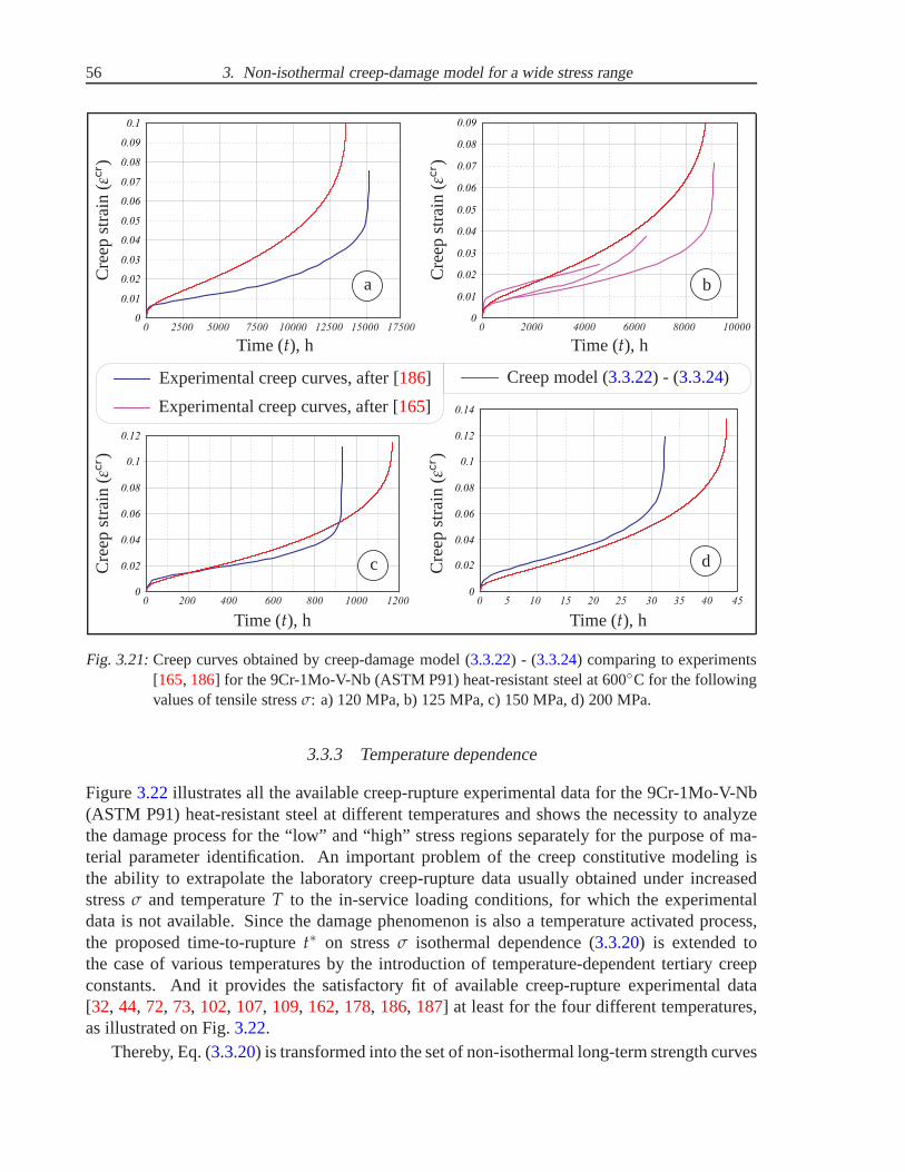
56 3. Non-isothermal creep-damage model for a wide stress range
0
0 02.
0 04.
0 06.
0 08.
0 2500 5000 7500 10000 12500 15000 17500
0 0. 7
0 0. 5
0 0. 3
0 0. 1
0
0 02.
0 04.
0 06.
0 0. 7
0 2000 4000 6000 8000 10000
0 0. 5
0 0. 3
0 0. 1
0
0 02.
0 0. 4
0 0. 8
0 1.
0 200 400 600 800 1000 1200
0 0. 6
0 1. 2
0
0 02.
0 0. 6
0 0. 8
0 1.
0 12.
0 5 10 15 20 25 30 35 40 45
0 0. 4
0 0. 9
0.1
0 0. 8
0 0. 9
0 1. 4
a b
c d
Time (t), hTime (t), h
Time (t), hTime (t), h
Cre
epst
rain
(εcr )
Cre
epst
rain
(εcr )
Cre
epst
rain
(εcr )
Cre
epst
rain
(εcr )
Experimental creep curves, after [186]
Experimental creep curves, after [165]
Creep model (3.3.22) - (3.3.24)
Fig. 3.21:Creep curves obtained by creep-damage model (3.3.22) - (3.3.24) comparing to experiments[165, 186] for the 9Cr-1Mo-V-Nb (ASTM P91) heat-resistant steel at 600C for the followingvalues of tensile stressσ: a) 120 MPa, b) 125 MPa, c) 150 MPa, d) 200 MPa.
3.3.3 Temperature dependence
Figure3.22illustrates all the available creep-rupture experimentaldata for the 9Cr-1Mo-V-Nb(ASTM P91) heat-resistant steel at different temperaturesand shows the necessity to analyzethe damage process for the “low” and “high” stress regions separately for the purpose of ma-terial parameter identification. An important problem of the creep constitutive modeling isthe ability to extrapolate the laboratory creep-rupture data usually obtained under increasedstressσ and temperatureT to the in-service loading conditions, for which the experimentaldata is not available. Since the damage phenomenon is also a temperature activated process,the proposed time-to-rupturet∗ on stressσ isothermal dependence (3.3.20) is extended tothe case of various temperatures by the introduction of temperature-dependent tertiary creepconstants. And it provides the satisfactory fit of availablecreep-rupture experimental data[32, 44, 72, 73, 102, 107, 109, 162, 178, 186, 187] at least for the four different temperatures,as illustrated on Fig.3.22.
Thereby, Eq. (3.3.20) is transformed into the set of non-isothermal long-term strength curves

3.3. Non-isothermal long-term strength and tertiary creepmodeling 57
(see Fig.3.22) by the introduction of two Arrhenius-type functions in thefollowing way
t∗(T) =B(T)
σ1−k [σ0(T)]n−1 + σn−k, (3.3.32)
whereB(T) denotes the temperature-dependent creep-rupture parameter
B(T) = Bf exp
(
Qf
R T
)
, (3.3.33)
and σ0(T) is the temperature-dependent stress, which denotes the transition from ductile tobrittle damage mode
σ0(T) = Bσ exp
(
Qσ
R T
)
. (3.3.34)
In Eqs (3.3.33) - (3.3.34) the dependence on temperature is introduced by the Arrhenius-typefunctions with the following tertiary creep material parameters:Bf = 2.0 ··· 10−14 [h···MPa(n−k)],Qf = 698000[J··· mol−1], Bσ = 0.205 MPa,Qσ = 44940[J··· mol−1] and universal gas constantR = 8.314 [J··· K−1 ··· mol−1].
The isothermal creep-damage model (3.3.22) - (3.3.24) is transformed into the non-isothermal form consisting of the creep constitutive equation (3.3.35) for the creep strain rateand two damage evolution equations (3.3.37) - (3.3.38) for the damage accumulation rate. Thenon-isothermal creep constitutive equation describing primary and steady-state creep behaviouris formulated analogously to Eq. (3.3.22) as follows
εcr = A(T)σ [1 + α exp (−β εcr)]
1 − ωb
+A(T)
[σ0(T)]n−1
(
σ [1 + α exp (−β εcr)]
1 − ωd
)n
, (3.3.35)
where the temperature-dependent secondary creep parameters A(T) andσ0(T) are formulatedusing the Arrhenius-type functions (3.1.5) and (3.1.8) as follows
A(T) = A1(T) = Ac exp
(
−Qc
R T
)
and σ0(T) = Aσ exp
(
−Qσ
R T
)
. (3.3.36)
In notations (3.3.35) - (3.3.36) the values of secondary creep parameters for the 9Cr-1Mo-V-Nb(ASTM P91) steel defined in Sect.3.1 are following: n = 12, Ac = A01 = 2300 [MPa−1/h],Qc = Q1 = 200000 [J··· mol−1], Aσ = 0.658 MPa,Qσ = 36364 [J··· mol−1] and the universal gasconstantR = 8.314 [J··· K−1 ··· mol−1]. The values of primary creep parameters in Eq. (3.3.35)defined in Sect.3.2are following:α = 0.5 andβ = 300.
Taking into account the time-to-rupture function (3.3.32), the non-isothermal damage evo-lution equations describing tertiary creep behaviour and fracture are formulated analogously toEq. (3.3.24) for the brittle damage parameterωb
ωb =σ1−k [σ0(T)]n−1 + σn−k
B(T) (l1 + 1) (1 − ωb)l1(3.3.37)
and the ductile damage parameterωd
ωd =σ1−k [σ0(T)]n−1 + σn−k
B(T) (l2 + 1) (1 − ωd)l2, (3.3.38)

58 3. Non-isothermal creep-damage model for a wide stress range
10
100
400
10 10 10 10 10 102 3 4 5 6
11.5
1
1
0.5
Time to rupture (t∗), h
Str
ess
(σ),
MP
a
Ap
plic
atio
nra
ng
e
Low
Mo
der
ate
Hig
h
550C 600C 625C 650C
Transition stressσ0(T)
Experimental creep-rupture data, after:[32, 102, 162, 178] [44, 102, 107, 109, 162, 178, 186, 187] [72, 73, 107, 109] [32, 102, 107, 109, 162, 178]Stress range
High:
Moderate:550C 600C 625C 650C
t∗(T) =B(T)
σ1−k [σ0(T)]n−1 + σn−k
Fig. 3.22:Experimental creep-rupture data [32, 44, 72, 73, 102, 107, 109, 162, 178, 186, 187] at varioustemperatures for the 9Cr-1Mo-V-Nb (ASTM P91) heat-resistant steel fitted by the proposednon-isothermal Eq. (3.3.32) for long-term strengthcurves.
where the temperature-dependent tertiary creep parameters B(T) and σ0(T) are formulatedusing the Arrhenius-type functions as follows
B(T) = Bf exp
(
Qf
R T
)
and σ0(T) = Bσ exp
(
Qσ
R T
)
. (3.3.39)
In notations (3.3.37) - (3.3.39) the values of tertiary creep material parameters arel1 = 0.532,l2 = 17.383,Bf = 2.0 · 10−14 [h ··· MPa(n−k)], Qf = 698000 [J ··· mol−1], Bσ = 0.205 MPa,Qσ = 44940[J ··· mol−1] and the universal gas constantR = 8.314 [J··· K−1 ··· mol−1].
Numerical integration by time of the both creep constitutive equation (3.3.35) and damageevolution equations (3.3.37) - (3.3.38) with the defined values of temperatureT and stressσ pro-duce the creep strainεcr vs. timet dependence or uniaxialcreep curve. Using the non-isothermalcreep-damage model (3.3.35) - (3.3.39) one can obtain the valid uniaxialcreep curvesin thestress range from 0 MPa till 300 MPa and temperature range from 550C till 650C.
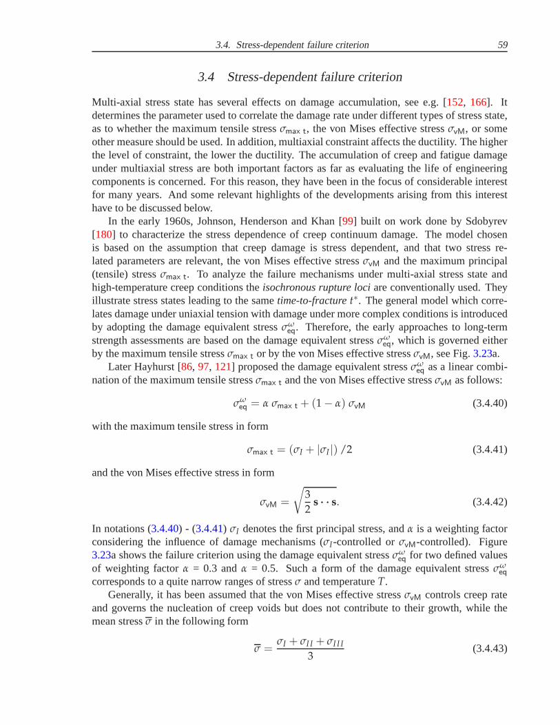
3.4. Stress-dependent failure criterion 59
3.4 Stress-dependent failure criterion
Multi-axial stress state has several effects on damage accumulation, see e.g. [152, 166]. Itdetermines the parameter used to correlate the damage rate under different types of stress state,as to whether the maximum tensile stressσmax t, the von Mises effective stressσvM, or someother measure should be used. In addition, multiaxial constraint affects the ductility. The higherthe level of constraint, the lower the ductility. The accumulation of creep and fatigue damageunder multiaxial stress are both important factors as far asevaluating the life of engineeringcomponents is concerned. For this reason, they have been in the focus of considerable interestfor many years. And some relevant highlights of the developments arising from this interesthave to be discussed below.
In the early 1960s, Johnson, Henderson and Khan [99] built on work done by Sdobyrev[180] to characterize the stress dependence of creep continuum damage. The model chosenis based on the assumption that creep damage is stress dependent, and that two stress re-lated parameters are relevant, the von Mises effective stressσvM and the maximum principal(tensile) stressσmax t. To analyze the failure mechanisms under multi-axial stress state andhigh-temperature creep conditions theisochronous rupture lociare conventionally used. Theyillustrate stress states leading to the sametime-to-fracturet∗. The general model which corre-lates damage under uniaxial tension with damage under more complex conditions is introducedby adopting the damage equivalent stressσω
eq. Therefore, the early approaches to long-termstrength assessments are based on the damage equivalent stressσω
eq, which is governed eitherby the maximum tensile stressσmax t or by the von Mises effective stressσvM, see Fig.3.23a.
Later Hayhurst [86, 97, 121] proposed the damage equivalent stressσωeq as a linear combi-
nation of the maximum tensile stressσmax t and the von Mises effective stressσvM as follows:
σωeq = α σmax t + (1 − α) σvM (3.4.40)
with the maximum tensile stress in form
σmax t = (σI + |σI |) /2 (3.4.41)
and the von Mises effective stress in form
σvM =
√
3
2s ··· ··· s. (3.4.42)
In notations (3.4.40) - (3.4.41) σI denotes the first principal stress, andα is a weighting factorconsidering the influence of damage mechanisms (σI-controlled orσvM-controlled). Figure3.23a shows the failure criterion using the damage equivalent stressσω
eq for two defined valuesof weighting factorα = 0.3 andα = 0.5. Such a form of the damage equivalent stressσω
eq
corresponds to a quite narrow ranges of stressσ and temperatureT.Generally, it has been assumed that the von Mises effective stressσvM controls creep rate
and governs the nucleation of creep voids but does not contribute to their growth, while themean stressσ in the following form
σ =σI + σI I + σI I I
3(3.4.43)

60 3. Non-isothermal creep-damage model for a wide stress range
-2.5 -2.0 -1.5 -1.0 -0.5 0 0.5 1.0 1.5
1.5
1.0
0.5
0
-0.5
-1.0
-1.5
-2.0
-2.5 -1 5.
- .1 0
- 50.
0
0.5
1 0.
1 5.
-1.5 -1.0 -0.5 0 0.5 1.0 1.5
a b
σI/σ
σI I
σ
σωeq = σmax t =
σI + |σI |
2σωeq = σvM
σωeq = α σmax t + (1 − α) σvM,
α = 0.3α = 0.5
σI/σ0
σI I
σ0
50 MPa75 MPa100 MPa125 MPa
t∗ =B
σ1−kmax t σn−1
0 + σn−kvM
Fig. 3.23:Formulation of multiaxial failure criteria using plane stress isochronous rupture loci:a) conventional approach, after [86, 97, 121], b) stress-dependent multi-axial failure criterionbased on long-term strength of the 9Cr-1Mo-V-Nb (ASTM P91) heat-resistant steel at 600C.
promotes the growth of the creep voids or cracks, refer to [155] for the details. In the torsionalcreep rupture tests [155] all of the specimens exhibited a ductile transgranular creep fractureof shear type. And larger creep deformations with many micro-voids were observed near thefracture surfaces. These results should be because the larger σvM and little σ existed in thetorsional creep specimens. It has been reported [155] that at higher stresses (meanwhile largerσ) a ductile fracture caused due to the larger deformation, which restrained the growth of creepvoids. But at lower stresses a brittle intergranular fracture occurred due to the sufficient growthof voids with slower creep deformations. At each stress state, creep deformation and nucleationof creep voids in a specimen at a higher stress are easily to occur due to the largerσvM, but thegrowth of voids is restrained by the larger deformation. With decreasing the applied stress, abrittle intergranular fracture mode should be present due to the growth of creep voids. How-ever, from tension to torsion the growth of creep voids becomes difficult due to the decreaseof σ. Therefore, it is suggested that in a specimen with existingof σ and smallerσvM, a brittleintergranular fracture should occur easily [155].
The new mixed stress-dependent failure criterion based oncreep-rupturediagram (3.3.20)of the 9Cr-1Mo-V-Nb (ASTM P91) heat-resistant steel at 600C was proposed for the multi-axial form of creep-damage model (3.3.22) - (3.3.24) as follows:
t∗ =B
σ1−kmax t σn−1
0 + σn−kvM
. (3.4.44)

3.4. Stress-dependent failure criterion 61
-1 5.
-1 0.
- 50.
0
0.5
1 0.
1 5.
-1 5.-1 0.
- 50.0
0.51 0.
1 5.
2 0E+04.
4 0E+04.
6 0E+04.
8 0E+04.
1 0E+05.
1 2E+05.
1 4E+05.
1 6E+05.
1 8E+05.
2 0E+05.
0
190 000 - 200 000
180 000 - 190 000
170 000 - 180 000
160 000 - 170 000
150 000 - 160 000
140 000 - 150 000
130 000 - 140 000
120 000 - 130 000
110 000 - 120 000
100 000 - 110 000
90 000 - 100 000
80 000 - 90 000
70 000 - 80 000
60 000 - 70 000
50 000 - 60 000
40 000 - 50 000
30 000 - 40 000
20 000 - 30 000
10 000 - 20 000
0 - 10 000
σI
σ0
σI I/σ0
Time torupture
t∗, h
Time to rupturet∗, h
Fig. 3.24:Isochronous damage surfacepresenting multiaxial stress-dependent failure criterion based onlong-term strengthof the 9Cr-1Mo-V-Nb (ASTM P91) heat-resistant steel at 600C.
The failure criterion (3.4.44) includes both the first principal stressσI and the von Mises effec-tive stressσvM, and therefore it is applicable for the complete stress range. Within the rangeof “high” stresses the creep damage is primarily ductile andleads to the necking of uniaxialspecimen, so it is governed by the von Mises effective stressσvM. Within the range of “low”stresses the creep damage is primarily brittle and leads to the long-term degradation of materialmicrostructure. In this case we assume that the creep damageis governed by the first principalstressσI. The “moderate” stress range is controlled by the both first principal stressσI and thevon Mises effective stressσvM. The set of isochronous rupture loci presented on Fig.3.23billustrates the idea of failure mode transition from brittle rupture for “low” stresses to ductilerupture for “high” stresses.
The stress dependence of damage can be presented byisochronous damage surface, analo-gous to a yield surface [166]. The isochronous damage surfaceshown on Fig.3.24illustratesthe alternative presentation of the failure criterion (3.4.44) for the multiaxial stress state. Thetime-to-rupturet∗ is plotted as a function of principal stressesσI andσI I. And it illustrates theplane stress conditions which lead to the sametime-to-rupturet∗ depending on range of stress.It shows that for the long test durations the creep failure isprimarily determined the first princi-ple stressσI. This assumption is confirmed by the multi-axial creep-rupture experiments for alot of materials including advanced heat-resistant steelsunder different stressσ and temperature
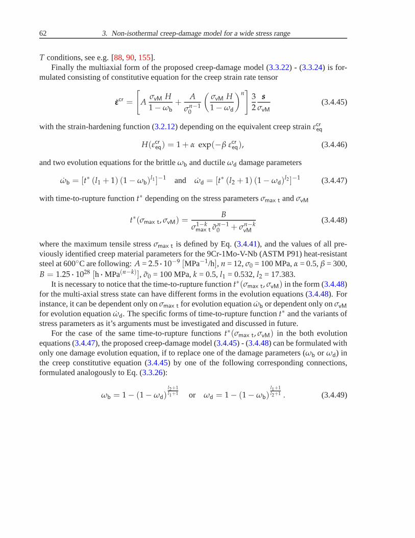
62 3. Non-isothermal creep-damage model for a wide stress range
T conditions, see e.g. [88, 90, 155].Finally the multiaxial form of the proposed creep-damage model (3.3.22) - (3.3.24) is for-
mulated consisting of constitutive equation for the creep strain rate tensor
εεεcr =
[
AσvM H
1 − ωb
+A
σn−10
(
σvM H
1 − ωd
)n]
3
2
sss
σvM
(3.4.45)
with the strain-hardening function (3.2.12) depending on the equivalent creep strainεcreq
H(εcreq) = 1 + α exp(−β εcreq), (3.4.46)
and two evolution equations for the brittleωb and ductileωd damage parameters
ωb = [t∗ (l1 + 1) (1 − ωb)l1 ]−1 and ωd = [t∗ (l2 + 1) (1 − ωd)
l2 ]−1 (3.4.47)
with time-to-rupture functiont∗ depending on the stress parametersσmax t andσvM
t∗(σmax t, σvM) =B
σ1−kmax t σn−1
0 + σn−kvM
(3.4.48)
where the maximum tensile stressσmax t is defined by Eq. (3.4.41), and the values of all pre-viously identified creep material parameters for the 9Cr-1Mo-V-Nb (ASTM P91) heat-resistantsteel at 600C are following:A = 2.5 ··· 10−9 [MPa−1/h], n = 12,σ0 = 100 MPa,α = 0.5,β = 300,B = 1.25 ··· 1028 [h ··· MPa(n−k)], σ0 = 100 MPa,k = 0.5,l1 = 0.532,l2 = 17.383.
It is necessary to notice that the time-to-rupture functiont∗(σmax t, σvM) in the form (3.4.48)for the multi-axial stress state can have different forms inthe evolution equations (3.4.48). Forinstance, it can be dependent only onσmax t for evolution equationωb or dependent only onσvM
for evolution equationωd. The specific forms of time-to-rupture functiont∗ and the variants ofstress parameters as it’s arguments must be investigated and discussed in future.
For the case of the same time-to-rupture functionst∗(σmax t, σvM) in the both evolutionequations (3.4.47), the proposed creep-damage model (3.4.45) - (3.4.48) can be formulated withonly one damage evolution equation, if to replace one of the damage parameters (ωb or ωd) inthe creep constitutive equation (3.4.45) by one of the following corresponding connections,formulated analogously to Eq. (3.3.26):
ωb = 1 − (1 − ωd)l2+1l1+1 or ωd = 1 − (1 − ωb)
l1+1l2+1 . (3.4.49)

4. CREEP ESTIMATIONS IN STRUCTURAL ANALYSIS
In Chapters2 and3 we introduced creep constitutive and damage evolution equations for themodeling of creep in engineering materials. The objective of Chapt.4 is the application ofcreep constitutive models to structural analysis. In Sect.4.1 we start with the discussion ofbasic steps in modeling of creep in structures with the application of finite element method(FEM). The advantages of FEM application and creep analysisprocedures in a commercialFEM-based software with conventional and user-defined constitutive models are highlighted.Section4.2is devoted to the introduction of benchmark problem conceptin the frames of struc-tural mechanics, description of its main purposes in creep mechanics and verification steps fora reliability assessment. As examples, two benchmark problems of creep-damage mechanicswhich can be solved by approximate numerical methods are presented. The reference solu-tions are compared with the finite element solutions by ANSYSand ABAQUS finite elementcodes with user-defined creep model subroutines. To discussthe applicability of the devel-oped techniques to real engineering problems two examples of numerical life-time assessmentwith application of creep-damage models for initial-boundary value problems are presented inSects4.3 and4.4. The purpose of Sect.4.3 is the numerical creep behavior modeling of theT-piece pipe weldment made of the 9Cr-1Mo-V-Nb (ASTM P91) heat-resistant steel. The ini-tially transversally-isotropic creep-damage model developed in Sect.2.2.1is incorporated in thecommercial FEM-based CAE-software ANSYS. The numerical analysis results of the weldedstructure qualitatively agree with available experimental observations and confirm the facts ofvarious creep and damage material properties in longitudinal and transversal directions of awelding seam. Finally, in Sect.4.4 an example of life-time assessment for the housing of aquick stop valve usually installed on steam turbines is presented. Long-term behavior of thiscomponents under approximately in-service loading conditions (constant internal pressure andconstant temperature) is simulated by the FEM. The results show that the developed in Chapt.3constitutive model is capable to reproduce specific features of creep and damage processes inengineering structures during the long-term thermal exposure.
4.1 Application of FEM to creep-damage analysis
The aim of creep modeling is to reflect basic features of creepin engineering structures includ-ing the development of inelastic deformations, relaxationand redistribution of stresses as wellas the local reduction of material strength. A model should be able to account for material de-terioration processes in order to predict long-term structural behavior, to estimate the in-servicelife-time of a component and to analyze critical zones of failure caused by creep. Structuralanalysis under creep conditions usually requires the following steps, proposed in [147, 152]:

64 4. Creep estimations in structural analysis
1. Assumptions must be made with regard to the geometry of thestructure, types of loadingand heating as well as kinematical constraints.
2. A suitable structural mechanics model (e.g. three-dimensional solids, beams, rods, platesand shells) must be applied based on the assumptions concerning kinematics of deforma-tions, types of internal forces (moments) and related balance equations.
3. A reliable constitutive model must be formulated to reflect time dependent creep defor-mations and processes accompanying creep like hardening/recovery and damage.
4. A mathematical model of the structural behavior (initial-boundary value problem) must beformulated including the material independent equations,constitutive (evolution) equa-tions as well as initial and boundary conditions.
5. Numerical solution procedures (e.g. the Ritz method, theGalerkin method, the finiteelement method) to solve non-linear initial-boundary value problems must be developed.
6. The verification of the applied models must be performed including the structural me-chanics model, the constitutive model, the mathematical model as well as the numericalmethods and algorithms.
For the numerical solution the direct variational methods,e.g. the Ritz method, the Galerkinmethod and the finite element method (FEM), are usually applied. In recent years the FEMhas become the widely accepted tool for structural analysis. The advantage of the FEM is thepossibility to model and analyze engineering structures with complex geometries, various typesof loadings and boundary conditions. General purpose finiteelement codes ABAQUS, AN-SYS, NASTRAN, COSMOS, MARC, ADINA, etc. were developed to solve various problemsin solid mechanics. In application to the creep analysis oneshould take into account that ageneral purpose constitutive equation which allows to reflect the whole set of creep and dam-age processes in structural materials over a wide range of loading and temperature conditionsis not available at present. Therefore, a specific constitutive model with selected internal statevariables, special types of stress and temperature functions as well as material constants identi-fied from available experimental data should be incorporated into the commercial finite elementcode by writing a user-defined material subroutine. The examples of manuals for the proceduresof user-defined subroutines implementation into the commercial FEM-based software ANSYSand ABAQUS can be found in [3, 22]. The ABAQUS and ANSYS finite element codes areapplied to the numerical analysis of creep in structures, e.g. [66, 140, 152, 170, 181, 182].
The standard features of the commercial FEM-based software(e.g., ANSYS and ABAQUS)includes only conventional creep models, refer to [1, 20]. Strain hardening, time hardening, ex-ponential, Graham and Blackburn models, etc. are proposed for the primary creep stage andGarofalo, exponential and Norton models, etc. are proposedfor the secondary creep stage. Us-ing standard creep models incorporated into FEM-based software it is impossible to model thetertiary creep stage accompanied with damage accumulationprocess and fracture, see Fig.4.1.In order to consider damage processes the user-defined subroutines are developed and imple-mented. The subroutines serve to utilize constitutive and evolution equations with damage statevariables, see Fig.4.1. In addition, they allow the postprocessing of damage, i.e.the creation ofcontour plots visualizing damage distributions.

4.1. Application of FEM to creep-damage analysis 65
Preprocessor,t := 0
Computing theStiffness Matrixand Force Vector
[KKK]t, [ fff ]t
Solving the Systemof AlgebraicEquations
[KKK]Tt [uuu]t = [ fff ]t
ConventionalCreep Laws
εεεcr =3
2
g(σvM)
σvM
sss
SolutionOutput
for Postprocessor
Postprocessor
Creep Laws
εεεcrt = gggε(σσσt, σσσbt
, ωωωt, T),σσσbt
= gggh(σσσt, σσσbt, ωωωt, T),
ωωωt = gggω(σσσt, σσσbt, ωωωt, T)
Updateεεεcr
t+∆t, σσσbt+∆t, ωωωt+∆t,
t := t + ∆t
ωωωt < ωωω∗
?
yes
yes
no
no
User-DefinedCreep Laws
User-definedCREEP Subroutine
is specified?
Fig. 4.1:Creep analysis procedures in a commercial FEM software withconventional creep laws andwith user-defined creep-damage models, after [148].

66 4. Creep estimations in structural analysis
4.2 Numerical benchmarks for creep-damage modeling
The concept of benchmarks is widely used in computational engineering mechanics and partic-ularly in creep-damage mechanics. Several benchmark problems based on the different creepconstitutive models are presented in [12, 16, 28, 29, 152, 2]. To consider both the creep and thedamage processes, a specific constitutive model with selected internal state variables, specialtypes of stress and temperature functions as well as material constants identified from avail-able experimental data should be incorporated into the commercial FE-code by writing a user-defined material subroutine, see e.g. [3, 22]. Thus benchmark problems are needed to verifythose developed subroutines. For these problems numericalor analytical reference solutionsare usually obtained. To conclude about the fact that the subroutines are correctly coded andimplemented, results of finite element computations must becompared with reference solutionsof benchmark problems.
4.2.1 Purposes and applications of benchmarks
An important question in the creep analysis is that on reliability of the applied models, numer-ical methods and obtained results. To assess the reliability of the developed subroutine as wellas the accuracy of the results with respect to the mesh density, type of finite element, the timestep, and the iteration methods, numerical benchmark problems are required. In [147, 152] thefollowing verification steps are proposed for the reliability assessment:
• Verification of developed finite element subroutines.To assess that the subroutines are cor-rectly coded and implemented, results of finite element computations must be comparedwith reference solutions of benchmark problems. Several benchmark problems have beenproposed in [29] based on an in-house finite element code. Below we recall closed formsolutions of steady-state creep in elementary structures,well-known in the creep mechan-ics literature. To extend these solutions to the primary andtertiary creep ranges we applythe Ritz and the time step methods. The advantage of these problems is the possibility toobtain reference solutions without a finite element discretization. Furthermore, they allowto verify finite element subroutines over a wide range of finite element types includingbeam, shell and solid type elements.
• Verification of applied numerical methods.Here the problems of the suitable finite ele-ment type, the mesh density, the time step size and the time step control must be analyzed.They are of particular importance in creep damage related simulations. Below these prob-lems are discussed based on numerical tests and by comparison with reference solutions.
• Verification of constitutive and structural mechanics models. This step requires creep testsof model structural components and the corresponding numerical analysis by the use ofthe developed techniques. Examples of recent experimentalstudies of creep in structuresinclude beams [40, 152], transversely loaded plates [112, 146, 152], thin-walled tubesunder internal pressure [115, 117], pressure vessels [66, 68], circumferentially notchedbars [87]. Let us note that the experimental data for model structures are usually lim-ited to short-term creep tests. The finite element codes and subroutines are designed

4.2. Numerical benchmarks for creep-damage modeling 67
to analyze real engineering structures. Therefore long term analysis of several typicalstructures should be performed and the results should be compared with data collectedfrom engineering practice of power and petrochemical plants. Below the examples of thecreep finite element analysis for the typical components of power-generation plants arediscussed.
4.2.2 Simply supported beam
To formulate a benchmark problem using the creep-damage analysis of the simply supportedaluminium alloy beam loaded by a distributed forceq [152] it is necessary to compare theresults obtained by the Ritz method with those of ABAQUS and ANSYS finite element codesincorporating the Kachanov-Rabotnov phenomenological creep-damege model [121]:
εεεcr =3
2
a σvMn
(1 − ω)msss
σvM
, ω = b[α σT + (1 − α)σvM]k
(1 − ω)lwith σT =
1
2(σI + |σI |) (4.2.1)
In this notationεεεcr is the creep rate tensor,sss is the stress deviator,σvM is the von Mises equiv-alent stress,σT is the maximum tensile stress,σI is the first principal stress,ω is the damageparameter andα represents the weighting factor of a material.a = 1.35 ··· 10−39 [MPa−n/h],b = 3.029 ··· 10−35 [MPa−k/h], n = 14.37,m = 10, k = 12.895,l = 12.5 andα = 0 are mate-rial constants after [116] for the aluminium alloy BS 1472 at 150±0.5C corresponding to themodel (4.2.1). Figure4.2shows the good agreement of the time variations of maximum deflec-tion and the normal stress obtained by the Ritz method and theFEM with the exception of thecalculations based on the ANSYS finite element code using element type SHELL43, see [21].
4.2.3 Pressurized thick cylinder
We incorporated the following creep constitutive equation(4.2.2) into the ABAQUS finite ele-ment code by the means of user-defined material subroutines
εεεcr =3
2
ε0
σ0
[
1 +
(
σvM
σ0
)n−1]
sss, ε0 ≡ aσ0 (4.2.2)
with the material constantsε0 = 2.5 ··· 10−7 1/h, σ0 = 100 MPa,n = 12 corresponding to9Cr1MoVNb steel at 600C obtained from the creep tests for both the linear and the powerlaw ranges data after [108, 110].
A reference solution of steady-state creep according to Eq.(4.2.2) for a thick cylinder sec-tion loaded by internal pressurep is obtained by means of two numerical procedures includingthe numerical integration and finding the root of a non-linear algebraic equation using Mathcadpackage (for the details refer to [12]). The results obtained by the presented in [12] approximatemethod are applied to verify the finite element solution. Thesteady-state creep problem of thethick cylinder in the power law creep range is the standard benchmark. Thus the geometricaldata and the finite element model are assumed as given in the benchmark manual [2].
Figure4.3 illustrates a good agreement of the solutions based on the ABAQUS finite codeand the approximate numerical solutions for different values of the normalized pressurep inboth the linear and the power law ranges.

68 4. Creep estimations in structural analysis
a)0 10000 20000 30000 40000 50000 60000 70000 80000
5
10
15
20
25
30
t, h
wm
ax,m
m
Ritz Method
ABAQUS, S4R5
ABAQUS, CPS4R
ANSYS, SHELL 43
ANSYS, PLANE 42
b)0 10000 20000 30000 40000 50000 60000 70000 80000
80
100
120
140
160
180
200
220
240
t, h
σ max
,MP
a
Ritz Method
ABAQUS, S4R5
ABAQUS, CPS4R
ANSYS, SHELL 43
ANSYS, PLANE 42
l =100 mm, b=30 mm, h=80 mm
q=2 N/mm2
wmax σmaxl
b
h
Fig. 4.2:Creep-damage analysis results vs. time in the bottom layer of the middle cross-section of asimply supported beam obtained by the Ritz method and the finite element codes using shelland plane stress type finite elements: a) maximum deflection,b) normal stress
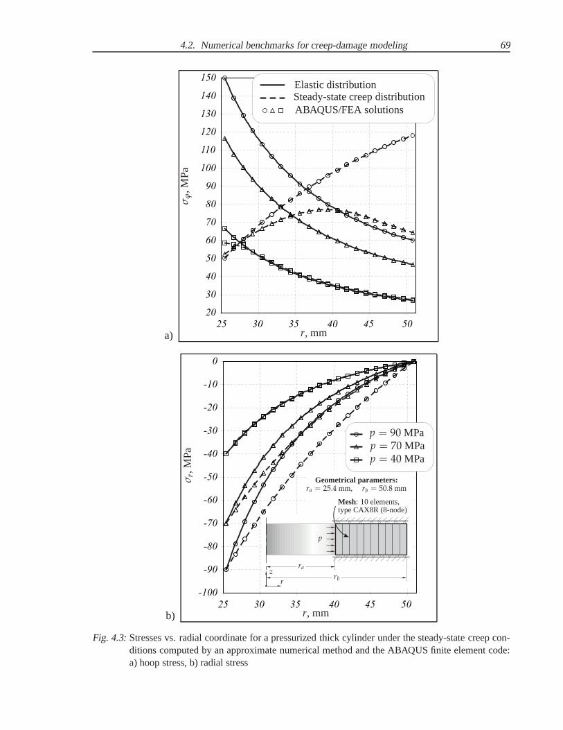
4.2. Numerical benchmarks for creep-damage modeling 69
a)
20
30
40
50
60
70
80
90
100
110
120
130
140
150
25 30 35 40 45 50
r, mm
σϕ, M
Pa
Elastic distributionSteady-state creep distributionABAQUS/FEA solutions
b)
-100
-90
-80
-70
-60
-50
-40
-30
-20
-10
0
25 30 35 40 45 50r, mm
σ r, M
Pa
p = 90 MPap = 70 MPap = 40 MPa
p
z
r
ra
rb
Mesh: 10 elements,type CAX8R (8-node)
Geometrical parameters:ra = 25.4 mm, rb = 50.8 mm
Fig. 4.3:Stresses vs. radial coordinate for a pressurized thick cylinder under the steady-state creep con-ditions computed by an approximate numerical method and theABAQUS finite element code:a) hoop stress, b) radial stress

70 4. Creep estimations in structural analysis
4.3 Anisotropic creep of a pressurized T-piece pipe weldment
This section is devoted to the practical application of the initially anisotropic model presentedin Sect.2.2.1and research work [80] to the long-term strength analysis in creep conditions ofa T-piece pipe weldment made of the 9Cr-1Mo-V-Nb (ASTM P91) heat-resistant steel. Theconstitutive model and appropriate creep parameters were based on the experimental creep andrupture data [95] of multi-pass weldmen considering the non-uniformity of the microstructurein the heat affected zone, in the base material and in the weldmetal of welding joint. For thepurpose of adequate creep behavior numerical modeling of the welding seam, the transversally-isotropic creep-damage model have been incorporated in thecommercial FEM-based CAE-software ANSYS. The model takes into account various creep and damage material propertiesin longitudinal and transversal directions of a welding seam. The performed numerical calcula-tions of the welded structure qualitatively agree with experimental data by MPA Stuttgart [104]and confirm the facts of rupture in corresponding zones of thewelding joint.
4.3.1 Formulation of structural model
The typical component of high-temperature power plants andchemical facilities equipment,i.e. pressurized T-piece weldment of two thick-walled pipes with different diameter was chosenas a test example. T-piece pipe weldment is subjected to the internal pressure of 18 MPa andtemperature 650C. Available creep experimental data for this structural component are theresults of experimental observations at the T-piece thick-walled pipe weldment creep under theinternal pressure 24 MPa at temperature 600C during 10 000 hours provided by MPA Stuttgart[104]. Geometrical solid model of the welding joint connecting two thick-walled pipes intoT-piece weldment was created in CAD-software SolidWorks using the add-on module for thedesign of welded structures [26] basing on the geometrical parameters after MPA Stuttgart [104]and standards GOST [197] and DIN [198], see Fig.4.4. The finite-element mesh of the T-pieceweldment and the series of creep-damage analyses were performed in CAE-software ANSYS.
Basing on previous experience in the creep simulation of welding joints, the weldment isconventionally divided into three zones with different microstructure and creep behaviour char-acter: parent material of pipes, heat-affected zone and welding seam, see Fig.4.4. But unlike toprevious investigations, the initial anisotropy of creep properties in the weld metal of weldingseam is considered. Fig.2.2 illustrates the creep curves of the 9Cr-1Mo-V-Nb (ASTM P91)steel at 650C under the tensile stress 100 MPa for three different zones in the welding joint.
4.3.2 Analysis of numerical results
The constitutive creep-damage model (2.2.24) - (2.2.25) with initial anisotropy of creep prop-erties and appropriate creep parameters presented in Sect.2.2.1 is applied to the long-termstrength analysis of the T-piece pipe weldment. In the frames of creep simulations the four life-time assessment with different combinations of creep properties in various structural zones areperformed. The first variant of analysis assumes the T-piecepipe weldment being homogenousand consisting of only steel P91 parental material. The second variant of the analysis is basedon previous approaches and assumes the weldment consistingof the three materials with differ-ent creep behaviour: parent metal of pipe, heat-affected zone and the weld metal properties in
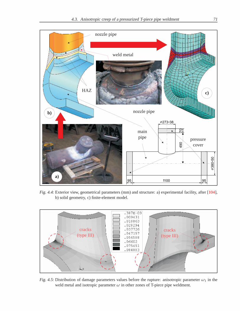
4.3. Anisotropic creep of a pressurized T-piece pipe weldment 71
110070
9595
38273
50
380
490
a)
b)
c)
pressurecover
mainpipe
nozzle pipe
nozzle pipe
HAZ
weld metal
Fig. 4.4:Exterior view, geometrical parameters (mm) and structure:a) experimental facility, after [104],b) solid geometry, c) finite-element model.
cracks(type III)
cracks(type III)
Fig. 4.5:Distribution of damage parameters values before the rupture: anisotropic parameterω1 in theweld metal and isotropic parameterω in other zones of T-piece pipe weldment.
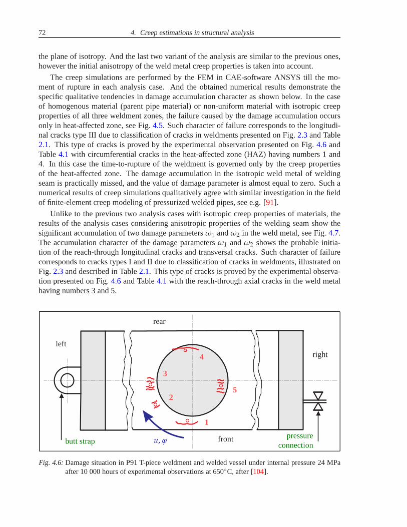
72 4. Creep estimations in structural analysis
the plane of isotropy. And the last two variant of the analysis are similar to the previous ones,however the initial anisotropy of the weld metal creep properties is taken into account.
The creep simulations are performed by the FEM in CAE-software ANSYS till the mo-ment of rupture in each analysis case. And the obtained numerical results demonstrate thespecific qualitative tendencies in damage accumulation character as shown below. In the caseof homogenous material (parent pipe material) or non-uniform material with isotropic creepproperties of all three weldment zones, the failure caused by the damage accumulation occursonly in heat-affected zone, see Fig.4.5. Such character of failure corresponds to the longitudi-nal cracks type III due to classification of cracks in weldments presented on Fig.2.3and Table2.1. This type of cracks is proved by the experimental observation presented on Fig.4.6 andTable4.1 with circumferential cracks in the heat-affected zone (HAZ) having numbers 1 and4. In this case the time-to-rupture of the weldment is governed only by the creep propertiesof the heat-affected zone. The damage accumulation in the isotropic weld metal of weldingseam is practically missed, and the value of damage parameter is almost equal to zero. Such anumerical results of creep simulations qualitatively agree with similar investigation in the fieldof finite-element creep modeling of pressurized welded pipes, see e.g. [91].
Unlike to the previous two analysis cases with isotropic creep properties of materials, theresults of the analysis cases considering anisotropic properties of the welding seam show thesignificant accumulation of two damage parametersω1 andω2 in the weld metal, see Fig.4.7.The accumulation character of the damage parametersω1 andω2 shows the probable initia-tion of the reach-through longitudinal cracks and transversal cracks. Such character of failurecorresponds to cracks types I and II due to classification of cracks in weldments, illustrated onFig. 2.3and described in Table2.1. This type of cracks is proved by the experimental observa-tion presented on Fig.4.6 and Table4.1 with the reach-through axial cracks in the weld metalhaving numbers 3 and 5.
1
2
3
4
5
u, ϕ
rear
front
rightleft
butt strappressure
connection
Fig. 4.6:Damage situation in P91 T-piece weldment and welded vessel under internal pressure 24 MPaafter 10 000 hours of experimental observations at 650C, after [104].

4.3. Anisotropic creep of a pressurized T-piece pipe weldment 73
Table 4.1:Damage situation in P91 T-piece weldment and welded vessel under internal pressure 24 MPaafter 10 000 hours of experimental observations at 650C, after [104].
PositionCrackposition
Crack directionCrack centerat u, mm
Crack depth,mm
1 HAZ Circumferential 10 ca. 10
2 Weld metal Circumferential 150 —
3 Weld metal T-joint (axial) 220 Through wall
4 HAZ Circumferential 435 10
5 Weld metal T-joint (axial) 640 Through wall
a)
b)
crack (type I)
crack (type II)
Fig. 4.7:Distribution of damage parameters values in the weld metal before the rupture: a) along thewelding directionω1, b) transversely to the welding directionω2.
74 4. Creep estimations in structural analysis
The numerical results obtained with the assumption of anisotropic creep properties in theweld metal have more reliable agreement with the creep experimental observations for this t-piece pipe weldment, illustrated on Fig.4.6 and Table4.1, and others welded pipe structures[96]. Alongside with the cracks with types III and VI caused by the critical damage accumu-lation in the heat-affected zone (see Fig.4.5), the experimental studies [104] report that thereach-through longitudinal cracks with types I and II are initiated by the transversally-isotropicdamage parameters accumulation in the weld metal (see Fig.4.7).
The principal result of the research [80] presented in Sects2.2.1 and 4.3 is to show theability of the continuum mechanics approach application tocreep simulations of weldmentsconsidering non-uniformity of microstructure and anisotropic creep properties of weld metal.Consideration of transversely-isotropic creep properties of weld metal allows to predict the localzones of damage accumulation and probable cracks initiation with better qualitative accuracy.This assumption correlates with the experiments [104] obtained by MPA Stuttgart during the in-service observations for the similar structures. The obtained numerical results demonstrate thenecessity of the subsequent creep-rupture experiments forthe different weldment zones (parentmaterial, heat-affected zone and weld metal). The availability of the comprehensive creep-rupture experimental data will allow to simulate the long-term strength behaviour of weldmentsmore accurately under the in-service loading conditions.
4.4 Creep-damage analysis of power plant components
For the high-temperature components with complex geometry(e.g. pressure piping systems andvessels, rotors and turbine blades, casings of valves and turbines, etc.), where neither analyticalnor experimental reference stresses are available, the computer-based finite element analysis(FEA) is used, e.g. [30, 76, 96, 152]. The component is “broken down” into an aggregate offinite elements (FE) with prescribed properties. The computer analysis evaluates the responseof the component as a whole and enables the stresses and strains at any given point to be deter-mined. A detailed picture of the results distribution within the component is produced. In itssimplest form the FEA may only be applied to analyse the elastic stresses, but the knowledge ofthe creep properties of the material enables a long-term strength analysis or life-time assessmentto be performed.
4.4.1 Previous experience in FEA
The development of computational continuum damage mechanics (CDM) now allows FEA tobe performed using physically based constitutive equations to describe the material behavior.This enables the full time dependent behavior of a structureto be modeled, including, by the in-put of ductility values, the transition from generalized damage to discrete crack growth. Increas-ing speed and data storage capacity of computer workstations rapidly reduces the time requiredfor such computations. However, the procedure is critically dependent upon the availability ofvalidated multi-axial constitutive equations for deformation and damage over the mechanisticregimes encountered [89, 152].
Modern power-generation plants are required to provide high standards of reliability andavailability, which principally depends on the operating conditions, optimal structural design

4.4. Creep-damage analysis of power plant components 75
and the applied constructional materials. The reliabilityand safety of the whole power systemdepends greatly on the way in which the main power unit components such as the turbine, boilerand generator are operated. The operating conditions of those devices are usually very complexand involve many unsteady mechanical and thermal loads which in consequence determinethe stress states of the particular components. The durability of the steam turbine should beconsidered in terms of the durability of its main components, which can be divided into twomajor groups, mainly the shells (casings, valve housings) and rotating parts (rotors).
The thermal and mechanical loadings within the operation conditions usually lead to degra-dation of material owing to intensive interactions of many failure modes such as local plasticity,high temperature creep, damage, corrosion, fatigue and cracking. Interactions of main modesof degradation are complex in appropriate numerical modelling and difficult for the numericallybased life-time predictions. For instance, creep and damage can be intensified by the processof locally variable high thermal stresses during cycles of loading and unloading. Growing de-mands on safe, reliable and economic operation ask for a sufficient life-time prolongation ofthe critical power plant elements. A lot of numerical investigations by different laboratoriesbased on CDM and FEA presenting long-term strength analysesand life-time assessments ofhigh-temperature steam-turbine components were published recently, e.g. [38, 39, 98, 158].
In the framework of this dissertation several FEM-based life-time assessments of high-temperature power plant components were performed using the formulated in Sect.2 consti-tutive creep-damage models:
• The numerical investigations of long-term strength behaviour started with the applica-tion of conventional Kachanov-Rabotnov-Hayhurst creep-damage model [40, 89, 152] toisothermal creep-damage simulation [77]. As the component to be analysed the casingof a steam turbine reheat control valve was chosen. Such a component has to control thesteam flow into an intermediate pressure steam turbine. The investigation has proved thehigh efficiency of FEM-based life-time assessments with theapplication of conventionalCDM-based creep models.
• Within the frames of the research work [79] two conventional creep-damage models wereapplied to the isothermal simulation of the mechanical behaviour of a steam turbine ro-tor in its in-service conditions. These models were the isotropic Kachanov-Rabotnov-Hayhurst model [40, 89, 152] and the Murakami-Ohno [141, 142] model with damageinduced anisotropy presented in Sect.2.2.2. Numerical solutions of the initial-boundaryvalue problems have been obtained by FEM using solid axisymmetrical type finite el-ements. For the purpose of adequate long-term strength analysis both isotropic andanisotropic creep-damage models have been implemented in FE-code of the commer-cial CAE-software ANSYS. Obtained simulation results for asteam turbine rotor showthe significant sensitivity of life-time assessment to the type of material model.
• Thereafter, the conventional Kachanov-Rabotnov-Hayhurst creep-damage model [40, 89,152] was extended to the case of variable temperature and strainhardening consider-ation, as presented in Sect.2.1. A technique for the identification of material creepconstants based on the available family of experimental creep curves (see AppendixA)was presented in [114, 129]. The resulting non-isothermal model with the appropriate

76 4. Creep estimations in structural analysis
creep material parameters [113] were incorporated into the FE-code of the CAE-softwareABAQUS. It was applied to the long-term strength analysis ofa pressurized thick-walledpipe exposed to the non-uniform heating for the verificationpurposes and for the illus-tration of basic features of creep-damage character, referto [129]. Than the model wasapplied to the non-isothermal life-time assessments underin-service loading conditionsof such power plant components, as the casing of a steam turbine control-stop valve [114],the casing of a steam turbine bypass valve [130], housing of a high-pressure gas turbine[131], and the casing of a steam turbine quick-stop valve [132]. The obtained numeri-cal results confirmed the influence on non-uniform temperature field on the final stressand strain fields redistribution before the failure. However, the time-to-rupture values un-der the in-service loading conditions were overestimated,because the applied model issuitable only for the narrow range of the high stresses.
4.4.2 Steam turbine quick-stop valve
Finally, we must discuss several results of long-term analysis obtained by application of thenew creep-damage constitutive model developed in Chapt.3 to creep behaviour simulation ofa power plant component. As the component to be analysed the casing of a steam turbinequick-stop valve [54, 55, 56], illustrated on Fig.4.8, was chosen.
Application
If the steam turbine is tripped it is essential to have a fast and reliable quick stop function forprotection of the turbine. The steam turbine quick stop valve (VQS) is designed for this purpose[55]. A mechanical spring is used for the emergency shut-off. The closing time is typically lessthan 0.2 s for full stroke. On request shorter closing time isavailable. The emergency quickclose function achieves maximum protection for the steam turbine. The valves are equippedwith on-line exercise capability that demonstrates freedom of movement of tripping componentswithout affecting steam flow. The VQS valve is used together with the turbine flow control valve(VPC), as illustrated in Fig.4.8. The VPC valve is designed for regulating the steam flow fromstart-up to full load. As an option the VPC valve can be equipped with a quick closing function.The low total pressure drop over the valves improves the energy efficiency of the installation,thus improving the power production. Each valve is independently calculated and designedaccording to the relevant operational conditions.
Design features
The VQS and VPC valves design is of angle type and is based on the well proven design ofstop valve type VS. As far as, the drawings of the VQS valve casing were not accessible fromopened sources, it was decided to use the drawing of VS valve casing available from [56] andillustrated on Fig.4.8for the modeling of 3D solid geometry in the CAD-software SolidWorks.The VS valve casing [56], fully machined of forged CrMo low alloy steel or carbon steel,including X10CrMoVNb91 (F91) steel, is designed to minimize material stresses as well asto fit the requirements of the piping system with regard to material, pressure class and pipingconnections [54]. An even material distribution is essential to minimize the material stresses.

4.4. Creep-damage analysis of power plant components 77
By using the homogenous forged material, an accurate and controlled wall thickness, i.e. asmooth surface, is achieved. For severe operating conditions with large temperature variations,a continuous preheating of the valve inlet side is recommended. The VS valve is designed to beoperated by an actuator, and depending on the actuating force and project preference, any typeof actuator can be selected: pneumatic, electrohydraulic or electromechanical. The unbalancedconfiguration of VS valve casing with tight design providingleakage tightness according toANSI B16.104 Class V was selected, see Fig.4.8. The maximum capacity of the VQS valveis 7500 Kv or 8660 Cv, the maximum inlet pressure class corresponds to DIN-PN 640 (ANSI#4500), the maximum outlet pressure class corresponds to DIN-PN 250 (ANSI# 1500). Flowpath in angle body of the VQS valve means low pressure drop dueto pressure recovery in theoutlet cone, refer to [54].
Review of FEA results
The 3D-solid geometry of the valve casing designed in the CAD-software SolidWorks is trans-ferred to the FEM-based CAE-software ABAQUS and meshed with7740 solid 8-noded finiteelements (type 3CD8R, refer to [1]) providing totally 10085 nodes, as illustrated on Fig.4.9.The analysed main part of the valve casing is simplified to symmetrical geometry with appliedsymmetry boundary conditions on the cross-section surface. The main load on the valve cas-ing is the internal pressure 20 MPa which is considered as constant over time and normal foroperating conditions due to the service applications. As far as the geometry of a valve actuatoris not taken into account, its effect is replaced with balance pressurepnoz applied to the outersurface of nozzle with opposite sign, as illustrated on Fig.4.9. It is calculated as follows
pnoz =pint ··· Aact
Anoz= 8.67 (MPa), (4.4.3)
wherepint = 20 MPa is the internal pressure in the valve,Aact = 1.24 ··· 104 mm2 is the area ofthe actuator cross-section andAnoz = 2.85 ··· 104 mm2 is the area of the actuator cross-section.
Additional damage due to fatigue caused by the transient operation modes of a steam tur-bine, e.g. during start-up and shut down, is not considered here. The modern experienceof steam turbines manufacturers [101] shows the 9-12%Cr advanced heat-resistant steels areused for valve casings or turbine housings manufactured by casing or forging processes. Thus,the material of the analyzed valve casing is assumed to be the9Cr-1Mo-V-Nb (ASTM P91)heat-resistant steel. As the valve is considered to operateat temperature 600C, the values ofYoung’s modulusE = 1.12 ··· 105 MPa, Poisson’s rationµ = 0.3 and thermal expansion coefficientα = 1.26 ··· 10−5 K−1 are taken from [66]. Finally, for the transient creep process simulation,the isothermal form of the creep constitutive model developed in Chapt.3 is applied to pre-dict the creep damage in the valve casing. The creep constitutive equation (3.4.45) with thestrain-hardening function (3.4.46) and the damage evolution equations (3.4.47) with the time-to-rupture function (3.4.48) including all the corresponding creep materials parameters sum-marized in Sect.3.4 are incorporated in FE-code of CAE-software ABAQUS by the means ofuser-defined creep subroutine. The proposed model is able toreflect the basic features of stressredistribution in the structural component. Furthermore,it allows us to predict the locations forthe maximum creep damage and the life-time of the structuralcomponent till failure.

78 4. Creep estimations in structural analysis
VQS
SteamTurbine
Heat RecoverySteam Generator
Condenser
Condensate Pump
Control Components Inc.
VPC
Fig. 4.8:Typical installation of the steam turbine quick stop valve in a power station, after [55, 56].
Internal pressure: 20 MPa
Balanceloading:-8.67 MPa
FE-Model:C3D8R (8 Nodes)7740 Elements10085 Nodes
Fig. 4.9:ABAQUS mathematical model of VQS: geometry, loadings and FE-mesh.

4.4. Creep-damage analysis of power plant components 79
The creep-damage behavior simulation of the valve casing with the previously mentionedinitial-boundary conditions and material properties has predicted the failure of the componentin t∗ = 164000 hours = 18.7 years. The obtained FEA results show thecritical damage accu-mulation in two locations. The first location is situated on the outer surface of the valve casingas illustrated on Fig.4.10and is caused by the brittle damage parameterωb critical concentra-tion. In this possible place of brittle rupture initiation the damage accumulation is dominantlygoverned by the maximum tensile stressσmax t, as shown on Fig.4.10. The second locationis situated on the inner surface of the valve casing as illustrated on Fig.4.11and is caused bythe ductile damage parameterωd critical concentration. In this possible place of ductile ruptureinitiation the damage accumulation is dominantly governedby the von Mises effective stressσvM, as shown on Fig.4.11. As far as the character of the both damage parameters (ωb andωd)evolution is found out to be equal in the both locations (see Fig. 4.12), the decision about thetype of rupture is done basing on the stress parameters (σmax t andσvM) redistribution character.The dominant stress parameter (σmax t or σvM) defines the type of rupture (brittle or ductile).Additionally, this assumption is proved by the different evolution character of the maximumprincipal total strainεtot in different rupture locations, illustrated on Fig.4.13. The comparisonof the creep curves shows, that the ductile rupture locationhas accumulated almost two timesmore creep strain than the brittle rupture location. Due to Fig. 4.13, the ductile rupture locationhas more prevalent tertiary creep stage of the creep curve, but in the both locations the ruptureoccurs in the same timet∗.
These results should be investigated further in order to findout how to come closer to real-ity. Such clarification could give important input for future improvements in high temperaturecomponent design. In this context, firstly the parameter identification should be optimized forthe relevant loading conditions, whereby also multi-axialexperiments should be used. More-over, it is very important to compare and review the numerical damage predictions with respectto experimental findings of uni-axial and multi-axial load cases.

80 4. Creep estimations in structural analysis
1.287.6814.0820.4826.8833.2839.6846.0852.4858.8865.2871.6878.08
1.326.5211.7316.9422.1427.3532.5637.7642.9748.1853.3958.5963.80
0.003.679.6715.6721.6627.6633.6639.6645.6551.6557.6563.6469.64
0.1120.1860.2600.3330.4070.4800.5540.6280.7010.7750.8490.9220.996
0
10
20
30
40
50
60
70
0 20000 40000 60000 80000 100000 120000 140000 160000 180000
a b
c
c
a
b
Time, h
Str
ess,
MP
a
Maximum tensile stress (σmax t)
Von Mises effective stress (σvM)
Brittlerupturelocation
σmax t, MPa
σmax t, MPaσmax t, MPa
Brittledamage
parameterωb
Fig. 4.10:Redistribution of the maximum tensile stressσmax t in the location of brittle rupture.

4.4. Creep-damage analysis of power plant components 81
4.5611.7018.8525.9933.1340.2847.4254.5661.7168.8575.9983.1390.28
a
3.8710.4116.9523.4930.0336.5743.1149.6656.2062.7469.2875.8282.36
b
0.005.3410.4515.5620.6725.7830.8936.0041.1146.2251.3356.4461.55
c
0.010.0330.0550.0780.1010.1230.1460.1680.1910.2140.2360.2590.282
0 20000 40000 60000 80000 100000 120000 140000 160000 180000
0
10
20
30
40
50
60
70
c
ab
Time, h
Str
ess,
MP
a
Maximum tensile stress (σmax t)
Von Mises effective stress (σvM)
Ductile rupturelocation
σvM, MPa
σvM, MPaσvM, MPa
Ductiledamage
parameterωd
Fig. 4.11:Redistribution of the von Mises effective stressσvM in the location of ductile rupture.
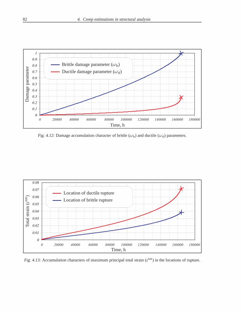
82 4. Creep estimations in structural analysis
0 20000 40000 60000 80000 100000 120000 140000 160000 180000
0
0.1
0.2
0.3
0.4
0.5
0.6
0.7
0.8
0.9
1
Time, h
Dam
age
par
amet
er Brittle damage parameter (ωb)
Ductile damage parameter (ωd)
Fig. 4.12:Damage accumulation character of brittle (ωb) and ductile (ωd) parameters.
0
0.01
0.02
0.03
0.04
0.05
0.06
0.07
0.08
0 20000 40000 60000 80000 100000 120000 140000 160000 180000
Time, h
Tota
lstr
ain
(εtot )
Location of brittle rupture
Location of ductile rupture
Fig. 4.13:Accumulation characters of maximum principal total strain(εtot) in the locations of rupture.

5. CONCLUSIONS AND OUTLOOK
A new appropriate approach to the phenomenological modeling of creep and damage behaviourbased on the well-known concepts of continuum damage mechanics and creep mechanics is de-veloped. In the framework of the thesis a comprehensive non-isothermal creep-damage modelfor a wide stress range is proposed in Chapt.3. It is based on the available creep and rup-ture experimental studies and microstructural observations for advanced heat resistant steels.The proposed approach takes into account the following features, which are important for thecomprehensive creep and damage modeling for structural analysis of industrial components:
• The uniaxial form of the proposed creep-damage model describing primary, secondaryand tertiary creep stages is formulated. The model consistsof the constitutive equationfor the creep strain rate governing steady-state creep behaviour and two damage evolu-tion equations for accumulation rates of brittle and ductile damage parameters governingtertiary creep behaviour and rupture. To take into account the primary creep behavior andstress relaxation effects a strain hardening function is utilized in the constitutive equation.
• The creep constitutive equation presented in Sect.3.1 shows the stress range dependentbehavior presenting the power-law to linear creep mechanism transition with a decreasingstress. To take into account the primary creep behavior a strain hardening function isutilized in Sect.3.2. The constitutive equation in the form of serious connection of linearand power-law components extended with strain hardening function well describes thecreep strain rates for a wide stress range and stress relaxation process under the loadingvalues relevant to in-service conditions of industrial applications.
• To characterize creep-rupture behavior the constitutive equation is generalized by intro-duction of two damage internal state variables and appropriate evolution equations inSect.3.3. The description of long-term strength behavior is based onthe assumption ofductile to brittle damage character transition with the decrease of stress. Two damageparameters show different ductile and brittle damage accumulation characters based onthe Kachanov-Rabotnov concept, but the similar time-to-rupture dependence.
• Since the creep and the damage effect are heat-activated processes, the creep constitutiveand damage evolution equations are extended with the temperature dependence using theArrhenius-type functions. Such a temperature dependence presented in Sects3.1and3.3is found applicable only for a quite narrow range of high temperatures.
• The set of creep material parameters for the 9Cr-1Mo-V-Nb (ASTM P91) heat-resistantsteel valid in the stress (0 – 300 MPa) and temperature (550 – 650C) ranges relevantto in-service loading conditions is identified in Sect.3.3. The identification procedure

84 5. Conclusions and Outlook
is based on manual fitting of the available experimental datapresented by the minimumcreep strain rate, time-to-rupture and creep-rupture strain vs. stress dependencies.
• The unified multi-axial form of the creep-damage model is presented in Sect.3.4. Toanalyze the failure mechanisms under multi-axial stress states the isochronous ruptureloci and time-to-rupture surface are presented. They illustrate that the proposed failurecriterion based on the dependence of time-to-rupture on stress include both the maximumtensile stress and the von Mises effective stress. But the measures of influence of the stressparameters are dependent on the level of stress with ductileto brittle failure transition.
• Finally in Sect.4.4 an example of numerical long-term strength analysis for a typicalpower plant component is presented. The obtained FEA results show that the developedapproach is capable to reproduce basic features of creep anddamage processes in en-gineering structures. And the assumptions of power-law to linear creep behaviour andductile to brittle damage mode transitions are really important for an adequate life-timeassessments and local damaged zones predictions under in-service loading conditions.
The proposed in this work creep-damage model is not yet well verified and optimized. The formof strain hardening function for the description of primarycreep stage proposed in Sect.3.2 isstill under question. Because the primary stages of the creep curves do not fit the experimentalcreep curves equally well under low and high levels of stress. Therefore, for the purpose oftesting and improvement the following future studies are planed:
• The strain hardening function proposed in Sect.3.2 probably need to be replaced withother more suitable concepts for the purpose of better description of primary creepstage. Possible variants are the modification of the strain hardening function with stress-dependent primary creep parameters or the application of kinematic hardening concepts,see e.g. [152]. The common approach used in the kinematic hardening concept is theintroduction of additional internal state variables such as back stress [134, 135] and hard-ening [46, 167] and appropriate evolution equations (the so-called hardening rules).
• The verification of the creep-damage model presented in Chapt. 3 should be performedusing solutions of benchmark problems specified for creep and damage mechanics. Themain problem while the model development was the lack of creep and rupture experi-mental data under the low level of stress. Thus, the accuracyof the creep-damage modelpredictions can be increased by a new creep material parameters identified using of ex-periments obtained under low and moderate stresses and higher temperature range. Theindependent creep-rupture tests under non-proportional loading (e.g. combined tensionand torsion) in a wide stress range are necessary to verify the new failure criterion.
• The algorithm and the procedure for the automatical or semi-automatical identification ofthe creep materials parameters applicable for any of the similar advanced heat-resistantsteels have to be developed. An application or a stand-alonesoftware for the identifi-cation should automatically fit the input experimental datafor the series of stresses andtemperatures and must output the values of creep material parameters. The identificationprocedure can be additionally visualized and extended withqueries to final user to definean identification options and to optimize the values of creepparameters.

A. IDENTIFICATION PROCEDURE OF CREEP MATERIALPARAMETERS
A.1 Secondary creep stage
The steady-state creep region of every creep curve from experimental data set(εd , td),(εd+1, td+1), . . . , (εq, tq), whered ≥ 2 and q ≤ f ( f is a number of experimental mea-surements), is approximated by least-squares regression method [199], using linear function
ε = εcrmin t, (A.1.1)
where the minimum creep strain rateεcrmin is the slope to be estimated from linear function(A.1.1) in the following form:
εcrmin =
[
(q − d)q
∑i=d
tiεi−
(
q
∑i=d
ti
)(
q
∑i=d
εi
)]
[
(q − d)q
∑i=d
t2i −
(
q
∑i=d
ti
)2] . (A.1.2)
The material constantsA andn for the relationship between creep strain rate and stressεcr =A σn can be determined from steady-state creep. In double logarithmic coordinates the creepstrain rate and stress theoretically must be connected by close to linear function, which can beapproximated by least-squares regression method [199], using linear function
lg εcrmin = lg A + n lg σ, (A.1.3)
where the creep exponentn is the slope of function (A.1.3), linear in double logarithmic scale.Specifyingεcrmin 1, εcrmin 2, . . . , εcrmin ξ as minimum creep rates at the fixed stressesσ1, σ2, . . . ,
σξ and fixed temperaturesT1, T2, . . . , Tϕ, whereξ is a number of experimental stresses andϕis a number of temperatures corresponding to experimental creep curves with secondary creepstage, constantn and the set of temperature dependent constantsAj (j = 1, 2, ..., ϕ) can beestimated from following relations, produced by least-squares regression method [199], usingapproximation function (A.1.3):
n =
ξξ
∑i=1
(
lg εcrmin i lg σi
)
−
(
ξ
∑i=1
lg εcrmin i
) (
ξ
∑i=1
lg σi
)
ξξ
∑i=1
lg σ2i −
(
ξ
∑i=1
lg σi
)2, (A.1.4)

86 A. Identification procedure of creep material parameters
lg Aj =
(
ξ
Σi=1
lg εcrmin i
)(
ξ
Σi=1
lg σ2i
)
−
(
ξ
Σi=1
(lg εcrmin i lg σi)
)(
ξ
Σi=1
lg σi
)
ξξ
Σi=1
lg σ2i −
(
ξ
Σi=1
lg σi
)2. (A.1.5)
The data array(Aj, Tj), where j = 1, 2, ..., ϕ, representing temperature dependence ofsecondary creep can be quite accurately approximated by theleast-squares regression method[199], using Arrhenius law function
A(T) = a exp
(
−h
T
)
, (A.1.6)
which is linear in half-logarithmic scale, and which contains the creep material constantsa andh, defined by notations
a =A(T1)
exp
(
−h
T1
) =A(T2)
exp
(
−h
T2
) and h =
T1 T2 ln
[
A(T1)
A(T2)
]
T1 − T2. (A.1.7)
A.2 Tertiary creep stage
Material constantslj define the shape of creep curve on the tertiary creep stage andgoverns thevalue of critical creep strain(ε∗1, ε∗2, . . . , ε∗ψ) corresponding to rupture time(t∗1 , t∗2 , . . . , t∗ψ) andstresses(σ1, σ2, . . . , σψ) for the number of fixed temperaturesT1, T2, ..., Tϕ:
li(Tj) = n − 1 +n
[
ε∗iA exp(−h/Tj) (σ∗
i )n t∗i
]
− 1
for (j = 1, 2, .., ϕ) and (i = 1, 2, ..., ψ),
(A.2.8)
whereψ is a number of experimental stress values corresponding to experimental creep curveswith tertiary creep stage andϕ is a number of temperature values.
The creep curves with an evident tertiary creep stage(σ1, σ2, . . . , σψ) are selected from thecomplete experimental stress range. The value oflj (j = 1, 2, ..., ϕ) for every temperaturevalue Tj is defined as an arithmetic mean value of the arrayli(Tj) (i = 1, 2, ..., ψ). For alltemperaturesT1, T2, ..., Tϕ the value of creep constantl is defined as a simple average value ofthe setlj (j = 1, 2, ..., ϕ).
The long-term strength curves corresponding to the number of fixed temperaturesT1, T2,. . . , Tϕ, i.e. failure time(t∗1 , t∗2 , . . . , t∗ψ) vs. applied stress(σ1, σ2, . . . , σψ) relations, can beapproximated by the least-squares regression method [199], using the following function, linearin a double logarithmic scale:

A.3. Primary creep stage 87
lg t∗ = − lg [(l + 1) B] − m lg σ, (A.2.9)
whereψ is a number of experimental stress values corresponding to the available experimentalcreep curves with tertiary creep stage. The constantm, which is not dependent on the tempera-ture, characterized the slope of the function (A.2.9), linear in a double logarithmic scale.
The constantm and the set of temperature dependent constantsBj (j = 1, 2, ..., ϕ) canbe estimated from following relations, produced by the least-squares regression method [199],using approximation function (A.2.9):
m = −
ψψ
∑i=1
(
lg t∗i lg σi
)
−
(
ψ
∑i=1
lg t∗i
) (
ψ
∑i=1
lg σi
)
ψψ
∑i=1
lg σ2i −
(
ψ
∑i=1
lg σi
)2, (A.2.10)
lg[
(l + 1) Bj
]
=
−
(
ψ
∑i=1
lg t∗i
) (
ψ
∑i=1
lg σ2i
)
−
[
ψ
∑i=1
(
lg t∗i lg σi
)
] (
ψ
∑i=1
lg σi
)
ψψ
∑i=1
lg σ2i −
(
ψ
∑i=1
lg σi
)2
.(A.2.11)
The data array(Bj, Tj), wherej = 1, 2, ..., ϕ, representing temperature dependence of ter-tiary creep can be quite accurately approximated by the least-squares regression method [199],using Arrhenius law function
B(T) = b exp(
−p
T
)
, (A.2.12)
which is linear in half-logarithmic scale, and contains creep material constantsb andp, definedby the following notations:
b =B(T1)
exp
(
−p
T1
) =B(T2)
exp
(
−p
T2
) and p =
T1 T2 ln
[
B(T1)
B(T2)
]
T1 − T2. (A.2.13)
A.3 Primary creep stage
The analytical formulation of the primary creep strain can be provided, if in Eq. (2.1.8) theinfluence of secondary and tertiary creep stages are neglected as follows:
ε = k ln
[
(1 + C) exp
(
θ
k
)
− C
]
with θ = a exp
(
−h
T
)
σn t, (A.3.14)
whereC andk are primary creep material constants to be defined.

88 A. Identification procedure of creep material parameters
For all the number of fixed temperaturesT1, T2, . . . , Tϕ (ϕ is the number of temperaturevalues) the creep curves with well marked primary creep stage are selected. Then for all selectedcreep curves the maximum creep strain values at the end of primary creep stage are obtained
for all fixed temperatures: (εT1max 1, εT1
max 2, . . . , εT1max φ), (εT2
max 1, εT2max 2, . . . , εT2
max φ), . . . , (εTϕ
max 1,
εTϕ
max 2, . . . , εTϕ
max φ). The next step assumes the extraction ofϕ creep curves with close or equalmaximum creep strain values, one for every temperature value. For example, the following
array is obtained after extraction:εTϕ
max 1, εT2max 2, . . . , εT1
max φ. Creep curves corresponding to
the array (εTϕ
max 1, εT2max 2, . . . ,εT1
max φ) are approximated by function (A.3.14) using least-squaresregression method [199] for the purpose of estimation of primary creep constantsCδ andkδ
(δ = 1, 2, ..., ϕ) for every temperature valueT1, T2, . . . , Tϕ.The final values ofC and k are obtained as simple average values for arraysCδ and kδ
(δ = 1, 2, ..., ϕ) as follows
C =C1 + C2 + ... + Cϕ
ϕand k =
k1 + k2 + ... + kϕ
ϕ. (A.3.15)
BIBLIOGRAPHY
[1] ABAQUS, Inc., Dassault Systemes,ABAQUS Analysis User’s Manual, Version 6.7 ed.,2007.64, 77
[2] ABAQUS, Inc., Dassault Systemes,ABAQUS Benchmarks Manual, Version 6.7 ed.,2007.66, 67
[3] ABAQUS, Inc., Dassault Systemes,ABAQUS User Subroutines Reference Manual, Ver-sion 6.7 ed., 2007.64, 66
[4] A BE, F., “Creep rates and strengthening mechanisms in tungsten-strengthened 9Crsteels,”Materials Science and Engineering, vol. A319-A321, pp. 770 – 773, 2001.55
[5] A BE, F., “Bainitic and martensitic creep-resistant steels,”Current Opinion in Solid Stateand Materials Science, vol. 8, no. 3-4, pp. 305 – 311, 2004.16, 48, 49
[6] A BE, F. and TABUCHI , M., “Microstructural and creep strength of welds in advancedferritic power plant steels,”Science and Technology of Welding and Joining, vol. 9, pp. 22– 30, 2004.16
[7] A LTENBACH, H., “Classical and nonclassical creep models,” inCreep and Damage inMaterials and Structures(ALTENBACH, H. and SKRZYPEK, J., eds.), pp. 45 – 95, Wien,New York: Springer, 1999. CISM Lecture Notes No. 399.7, 21
[8] A LTENBACH, H., “Creep analysis of thinwalled structures consideringdifferent structuremechanics models,” inContinuous Damage and Fracture(BENALLAL , A., ed.), pp. 243– 254, Paris et al.: Elsevier, 2000.29
[9] A LTENBACH, H., “Consideration of stress state influences in the material modelling ofcreep and damage,” inIUTAM Symposium on Creep in Structures(MURAKAMI , S. andOHNO, N., eds.), pp. 141 – 150, Dordrecht: Kluwer, 2001.29
[10] ALTENBACH, H., “Creep analysis of thin-walled structures,”Z. Angew. Math. Mech.,vol. 82, no. 8, pp. 507 – 533, 2002.3, 5, 6
[11] ALTENBACH, H., ALTENBACH, J., and NAUMENKO , K., Ebene Flachentragwerke.Berlin: Springer, 1998.16
[12] ALTENBACH, H., GORASH, Y., and NAUMENKO , K., “Steady-state creep of a pressur-ized thick cylinder in both the linear and the power law ranges,” Acta Mech., vol. 195,no. 1-4, pp. 263 – 274, 2008.33, 35, 66, 67
90 Bibliography
[13] ALTENBACH, H., HUANG, C., and NAUMENKO , K., “Creep damage predictions in thin-walled structures by use of isotropic and anisotropic damage models,”J. Strain Anal.,vol. 37, no. 3, pp. 265 – 275, 2002.7, 15, 19, 23, 29, 30
[14] ALTENBACH, H., KUSHNEVSKY, V., and NAUMENKO , K., “On the use of solid- andshell-type finite elements in creep-damage predictions of thinwalled structures,”Arch.Appl. Mech., vol. 71, pp. 164 – 181, 2001.15
[15] ALTENBACH, H., MORACHKOVSKY, O., NAUMENKO , K., and SYCHOV, A., “Geo-metrically nonlinear bending of thin-walled shells and plates under creep-damage condi-tions,” Arch. Appl. Mech., vol. 67, pp. 339 – 352, 1997.15
[16] ALTENBACH, H., NAUMENKO , K., and GORASH, Y., “Numerical benchmarks forcreep-damage modeling,”PAMM, vol. 7, 2007. 2 p., in press.66
[17] ALTENBACH, H., NAUMENKO , K., and GORASH, Y., “Creep analysis for a wide stressrange based on stress relaxation experiments,”Modern Physics Letter B, 2008. 6 p., inpress.35, 37
[18] ALTENBACH, J., ALTENBACH, H., and NAUMENKO , K., “Lebensdauerabschatzungdunnwandiger Flachentragwerke auf der Grundlage phanomenologischer Materialmod-elle fur Kriechen und Schadigung,”Technische Mechanik, vol. 17, no. 4, pp. 353 – 364,1997.15
[19] ALTENBACH, J., ALTENBACH, H., and NAUMENKO , K., “Egde effects in moderatelythick plates under creep damage conditions,”Technische Mechanik, vol. 24, no. 3-4,pp. 254 – 263, 2004.15
[20] ANSYS, Inc., Swanson Analysis Systems IP, Inc.,ANSYS Elements Reference, Release10.0 ed., 2005.64
[21] ANSYS, Inc., Swanson Analysis Systems IP, Inc.,ANSYS, Inc. Theory Reference, Re-lease 10.0 ed., 2005.67
[22] ANSYS, Inc., Swanson Analysis Systems IP, Inc.,Guide to ANSYS User ProgrammableFeatures, Release 10.0 ed., 2005.28, 64, 66
[23] ASBURY, F. E. and WILLOUGHBY, G., “Aging and creep behaviour of a Cr–Ni–Mnaustenitic steel,” inCreep Strength in Steel and High-Temperature Alloys: Proc.of aMeeting held at the University of Sheffield an 20-22 September 1972, (London, U.K.),pp. 144 – 151, Iron and Steel Institute, Metals Society, 1974. 10, 11
[24] ASHBY, M., SHERCLIFF, H., and CEBON, D., Materials: Engineering, Science, Pro-cessing and Design. New York et al.: Elsevier Ltd., 2007.1, 3, 7, 8, 9, 10, 11
[25] ASHBY, M. F. and JONES, D. R. H.,Engineering Materials 1: An Introduction to TheirProperties and Applications. Oxford: Butterworth Heinemann, 2nd ed., 1996.1, 2, 3, 8,10, 11, 46, 47, 48
Bibliography 91
[26] AVEDJAN, A. and SCHJOKIN, I., “Proektirovanie svarnyh konstrukcij v Solidworks (De-sign of welded structures in Solidworks, in Russ.),”SAPR and Graphics, vol. 2, pp. 51 –63, 2004.70
[27] BAILEY, R. W., “Creep of steel under simple and compound stress,”Engineering,vol. 121, pp. 129 – 265, 1930.10, 12, 34
[28] BECKER, A. A. and HYDE, T. H., “Fundamental tests of creep behaviour,” ReportR0027, NAFEMS, Glasgow, Scotland, U.K., June 1993.66
[29] BECKER, A. A., HYDE, T. H., SUN, W., and ANDERSSON, P., “Benchmarks for fi-nite element analysis of creep continuum damage mechanics,” Computational MaterialsScience, vol. 25, pp. 34 – 41, 2002.66
[30] BECKER, A. A., HYDE, T. H., and XIA , L., “Numerical analysis of creep in compo-nents,”J. Strain Anal., vol. 29, no. 3, pp. 185 – 192, 1994.74
[31] BECKITT, F. R., BANKS, T. M., and GLADMAN , T., “Secondary creep deformation in18% Cr–10% Ni steel,” inCreep Strength in Steel and High-Temperature Alloys: Proc.ofa Meeting held at the University of Sheffield an 20-22 September 1972, (London, U.K.),pp. 71 – 77, Iron and Steel Institute, Metals Society, 1974.11, 12
[32] BENDICK, W., HAARMANN , K., WELLNITZ , G., and ZSCHAU, M., “Eigenschaftender 9- bis 12%- Chromstahle und ihr Verhalten unter Zeitstandbeanspruchung,”VGBKraftwerkstechnik, vol. 73, no. 1, pp. 77 – 84, 1993.56, 58
[33] BETTEN, J., “Materialgleichungen zur Beschreibung des sekundaren und tertiarenKriechverhaltens anisotroper Stoffe,”ZAMM, vol. 64, pp. 211 – 220, 1984.29
[34] BETTEN, J.,Creep Mechanics. Berlin et al.: Springer-Verlag, 2005.1, 2, 13, 16, 17, 26,32, 51
[35] BETTEN, J., BORRMANN, M., and BUTTERS, T., “Materialgleichungen zur Beschrei-bung des primaren Kriechverhaltens innendruckbeanspruchter Zylinderschalen ausisotropem Werkstoff,”Ingenieur-Archiv, vol. 60, no. 3, pp. 99 – 109, 1989.15, 38
[36] BETTEN, J. and BUTTERS, T., “Rotationssymmetrisches Kriechbeulen dunnwandi-ger Kreiszylinderschalen im primaren Kriechbereich,”Forschung im Ingenieurwesen,vol. 56, no. 3, pp. 84 – 89, 1990.38
[37] BETTEN, J., EL-MAGD, E., MEYDANLI , S. C., and PALMEN , P., “Untersuchnungdes anisotropen Kriechverhaltens vorgeschadigter Werkstoffe am austenitischen StahlX8CrNiMoNb 1616,”Arch. Appl. Mech., vol. 65, pp. 121 – 132, 1995.15, 29
[38] BIELECKI , M., KARCZ, M., RADULSKI , W., and BADUR, J., “Thermo-mechanicalcoupling betwee the flow of steam and deformation of the valveduring start-up of the200 MW turbine,”Task Quarterly, vol. 5, no. 2, pp. 125 – 140, 2001.75

92 Bibliography
[39] BOLTON, J., “Analysis of structures based on a characteristic-strain model of creep,”Int.J. of Pressure Vessels & Piping, vol. 85, pp. 108 – 116, 2008.75
[40] BOYLE, J. T. and SPENCE, J.,Stress Analysis for Creep. London: Butterworth, 1983.16, 17, 32, 66, 75
[41] CANE, B. J., “The process controlling creep and creep fracture of2Cr–1Mo steel,”CEGB Report RD/LR 1979, Central Electricity Generating Board Research Laborato-ries, Leatherhead, UK, 1979.10, 11
[42] CANE, B. J. and BROWNE, R. J., “Representative stresses for creep deformation andfailure of pressurized tubes and pipes,”Int. J. of Pressure Vessels & Piping, vol. 10,no. 2, pp. 119 – 128, 1982.15
[43] CELLA , A. and FOSSATI, C., “Experience feedback on damage evaluation and residuallife prediction on chemical and petrochemical plants,” inHigh Temperature StructuralDesign(LARSSON, L. H., ed.), no. ESIS12, pp. 437 – 454, London, UK: MechanicalEngineering Publications, 1992.23
[44] CERJAK, H. and LETOFSKY, E., “The effect of welding on the properties of advanced9-12%Cr steels,”Science and Technology, vol. 1, no. 1, pp. 36 – 42, 1996.49, 50, 56, 58
[45] CHABOCHE, J., “Continuum damage mechanics a tool to describe phenomena beforecrack initiation,”Nuclear Engineering and Design, vol. 64, pp. 233 – 247, 1981.15
[46] CHABOCHE, J. L., “Constitutive equations for cyclic plasticity and cyclic viscoplastic-ity,” Int. J. Plasticity, vol. 5, pp. 247 – 302, 1989.84
[47] CHAN , W., MCQUEEN, R. L., PRINCE, J., and SIDEY, D., “Metallurgical experiencewith high temperature piping in Ontario Hydro,” inService Experience in OperationPlants(LARSSON, L. H., ed.), no. 21, pp. 97 – 105, New York, USA: ASME PVP, 1991.24, 25
[48] CHOSH, R. and MCLEAN, M., “High temperature deformation in engineering alloys-modelling for strain of load control,”Acta Metall. Mater., vol. 40, pp. 3075 – 3083,1992.7
[49] CHOUDHARY, B. K., PANIRAJ, C., RAO, K., and MANNAN , S. L., “Creep deformationbehavior and kinetic aspects of 9Cr-1Mo ferritic steel,”ISIJ International, vol. 41, pp. 73– 80, 2001.55
[50] CHOW, C. L. and WANG, J., “An anisotropic theory of elasticity for Continuum DamageMechanics,”J. Fracture, vol. 33, pp. 3 – 16, 1987.28
[51] COBLE, R. I., “A model for boundary diffusion controlled creep in polycrystalline ma-terials,”J. Appl. Phys., vol. 34, pp. 1679 – 1682, 1963.12
[52] COCKS, A. C. F. and LECKIE, F. A., “Creep rupture of shell structures subjected tocyclic loading,”Trans. of ASME. J. Appl. Mech., vol. 55, pp. 294 – 298, 1988.15

Bibliography 93
[53] COLLINS, M. J. in Creep Strength in Steel and High-Temperature Alloys: Proc.of aMeeting held at the University of Sheffield an 20-22 September 1972, (London, U.K.),p. 217, Iron and Steel Institute, Metals Society, 1974.10, 11
[54] CONTROL COMPONENTS INC., “Brochures: BTG valves product digest.” World WideWeb portable document format (PDF), http://www.ccivalve.com/pdf/605.pdf, 2002.76,77
[55] CONTROL COMPONENTS INC., “Data sheets: turbine quick stop valve (VQS), tur-bine flow control valve (VPC).” World Wide Web portable document format (PDF),http://www.ccivalve.com/pdf/552.pdf, 2003.76, 78
[56] CONTROL COMPONENTS INC., “Data sheets: turbine bypass stop valve (VS).” WorldWide Web portable document format (PDF), http://www.ccivalve.com/pdf/615.pdf,2005.76, 78
[57] CORDEBOIS, J. and SIDOROFF, F., “Damage induced elastic anisotropy,” inMechanicalBehaviours of Anisotropic Solids(BOEHLER, J. P., ed.), pp. 761 – 774, Boston: MartinusNijhoff Publishers, 1983.29
[58] DA C. ANDRADE, E. N., “On the viscous flow of metals, and allied phenomena,”Proc.R. Soc. Lond., vol. ALXXXIV, pp. 1 – 12, 1910.3
[59] DIMMLER , G., WEINERT, P., and CERJAK, H., “Investigations and analysis on the sta-tionady creep behaviour of 9-12% chromium ferritic martensitic steels,” inMaterialsfor Advances Power Engineering 2002: Proc. of the 7th Liege Conference(LECOMTE-BECKERS, J., CARTON, M., SCHUBERT, F., and ENNIS, P. J., eds.), no. 21 in ReiheEnergietechnik / Energy Technology, (Julich, Germany), pp. 1539 – 1550, Institut furWerkstoffe und Verfahren der Energietechnik, Forschungszentrum Julich GmbH, Sept.2002.10, 11
[60] DIMMLER , G., WEINERT, P., and CERJAK, H., “Extrapolation of short-term creep rup-ture data – The potential risk of over-estimation,”Int. J. Pres. Ves. & Piping, vol. 85,no. 1, pp. 55 – 62, 2008.10, 11
[61] DYSON, B. F., “Mechanical testing of high-temperature materials: modelling data-scatter,” inHigh-temperature structural materials(CAHN , R. W., EVANS, A. G., andMCLEAN, M., eds.), pp. 160 – 192, London et al.: Chapman & Hall, 1996.55
[62] DYSON, B. F. and MCLEAN, M., “Microstructural evolution and its effects on the creepperformance of high temperature alloys,” inMicrostructural Stability of Creep Resis-tant Alloys for High Temperature Plant Applications(STRANG, A., CAWLEY, J., andGREENWOOD, G. W., eds.), pp. 371 – 393, Cambridge: Cambridge University Press,1998.12, 15
[63] DYSON, B. F. and MCLEAN, M., “Micromechanism-quantification for creep consti-tutive equations,” inIUTAM Symposium on Creep in Structures(MURAKAMI , S. andOHNO, N., eds.), pp. 3–16, Dordrecht: Kluwer, 2001.12
94 Bibliography
[64] EARTHMAN , J. C., GIBELING , J. C., HAYES, R. W., andET. AL ., “Creep and stress-relaxation testing,” inMechanical Testing and Evaluation(KUHN, H. and MEDLIN , D.,eds.), no. 8 in ASM Handbook, chapter 5, pp. 783 – 938, Materials Park, OH, USA:ASM International, 2000.10, 12
[65] EGGELER, G., “The effect of long term creep on particle coarsening intempered marten-site ferritic steels,”Acta Metallurgica, vol. 37, no. 12, pp. 3225 – 3234, 1989.48
[66] EGGELER, G., RAMETKE , A., COLEMAN , M., CHEW, B., PETER, G., BURBLIES,A., HALD , J., JEFFEREY, C., RANTALA , J., DEWITTE, M., and MOHRMANN, R.,“Analysis of creep in a welded p91 pressure vessel,”Int. J. Pres. Ves. & Piping, vol. 60,pp. 237 – 257, 1994.55, 64, 66, 77
[67] ELLIS, F. V. and TORDONATO, S., “Calculation of stress relaxation properties for type422 stainless steel,”J. Pres. Vess. Tech., vol. 122, no. 1, pp. 66 – 71, 2000.37, 38, 42
[68] FESSLER, H. and HYDE, T. H., “The use of model materials to simulate creep behavior,”J. Strain Anal., vol. 29, no. 3, pp. 193 – 200, 1994.66
[69] FOLDYNA , V., JAKOBOVA , A., PRNKA , T., and SOBOTKA, J. inCreep Strength in Steeland High-Temperature Alloys: Proc. of a Meeting held at the University of Sheffield an20-22 September 1972, (London, U.K.), p. 230, Iron and Steel Institute, Metals Society,1974.10, 11
[70] FRANCOIS, D., PINEAU , A., and ZAOU, A., Comportement mecanique des materiaux:Viscoplasticite, endommagement, mecanique de la rupture, mecanique du contact. Paris:Hermes, 1993.8
[71] FROST, H. J. and ASHBY, M. F., Deformation Mechanism Maps. Oxford: PergamonPress, 1982.8, 12, 32
[72] GAFFARD, V., BESSON, J., and GOURGUES-LORENZON, A. F., “Creep failure modelof a tempered martensitic stainless steel integraiting multiple deformation and damagemechanisms,”Int. J. Fracture, vol. 133, pp. 139 – 166, 2005.33, 34, 36, 37, 48, 56, 58
[73] GAFFARD, V., GOURGUES-LORENZON, A. F., and BESSON, J., “High temperaturecreep flow and damage properties of the weakest area of 9Cr1Mo-NbW martensitic steelweldments,”ISIJ International, vol. 45, no. 12, pp. 1915 – 1924, 2005.33, 34, 36, 37,56, 58
[74] GAROFALO, F., Fundamentals of Creep and Creep-Rupture in Metals. New York: TheMacmillan Co., 1965.12
[75] GAUDIG , W., KUSSMAUL, K., MAILE , K., TRAMER, M., GRANACHER, J., andKLOOS, K. H., “A microstructural model to predict the multiaxial creep and damagein 12Cr Steel Grade at 550C,” in Microstructure and Mechanical Properties of Metal-lic High-Temperature Materials: Research Report/DFG(MUGHARBI, H., GOTTSTEIN,

Bibliography 95
G., MECKING, H., RIEDEL, H., and TOBOLSKI, J., eds.), pp. 192 – 205, Weinheim:Wiley-VCH, 1999.16
[76] GOOCH, D. J., “Remnant creep life prediction in ferritic materials,” in ComprehensiveStructural Integrity, Vol. 5, Creep and High-Temperature Failure (SAXENA , A., ed.),pp. 309–359, Amsterdam et al.: Elsevier, 2003.74
[77] GORASH, E., LVOV, G., HARDER, J., KOSTENKO, Y., and WIEGHARDT, K., “Compar-ative analysis of the creep behaviour in a power plant component using different materialmodels,” inCreep & Fracture in High Temperature Components: Design & Life Assess-ment Issues(SHIBLI , I. A., HOLDSWORTH, S. R., and MERCKLING, G., eds.), Proc.of the ECCC Creep Conf., (London, UK), pp. 573 – 581, ECCC, DESTech Publications,Inc., Sept. 2005.21, 75
[78] GORASH, Y., ALTENBACH, H., and NAUMENKO , K., “Modeling of primary and sec-ondary creep for a wide stress range,”PAMM, vol. 8, 2008. 2 p., in press.35, 37
[79] GORASH, Y. M., “Zastosuvannja izotropnoi ta anizotropnoi koncepcij poshkodzhuvan-nosti do rozrahunku tryvaloi micnosti rotoru parovoi turbiny v umovah vysokotemper-aturnoi povzuchosti (Application of isotropic and anisotropic concepts of damage to thelong-term strength analysis of the steam turbine rotor in high-temperature creep con-ditions, in Ukr.),” in Trans. of NTU “KhPI” (MORACHKOVSKIY, O. V., ed.), no. 21in Dynamics and Strength of Machines, pp. 92 – 101, Kharkiv, Ukraine: NTU “KhPI”Publishing Center, 2006.19, 29, 75
[80] GORASH, Y. N., LVOV, G. I., NAUMENKO , K. V., and ALTENBACH, H., “Analizvysokotemperaturnoj polzuchesti T-obraznogo soedinenija dvuh trub, nagruzhennyhdavleniem, s uchjotom anizotropii svojstv materiala v zonesvarnogo shva (High-temperature creep analysis of pressurized T-piece pipe weldment considering anisotropicmaterial properties in a welding zone, in Russ.),” inTrans. of NTU “KhPI”(MORACHKOVSKIY, O. V., ed.), no. 20 in Dynamics and Strength of Machines, pp.57 –66, Kharkiv, Ukraine: NTU “KhPI” Publishing Center, 2005.19, 24, 25, 26, 28, 70, 74
[81] GRAHAM , A. and WALLES, K. F. A., “On the extrapolation of creep data,” NGTEReport R247, 1961.8
[82] GUMMERT, P., “General constitutive equations for simple and non–simple materials,” inCreep and Damage in Materials and Structures(ALTENBACH, H. and SKRZYPEK, J.,eds.), pp. 1 – 43, Wien, New York: Springer, 1999. CISM Lecture Notes No. 399.5
[83] HARPER, J. G. and DORN, J. E., “Viscous creep of aluminum near its melting temper-ature,”Acta Metallurgica, vol. 5, no. 11, pp. 654 – 665, 1957.12
[84] HARPER, J. G., SHEPARD, L. A., and DORN, J. E., “Creep of aluminum under ex-tremely small stresses,”Acta Metallurgica, vol. 6, pp. 509 – 518, 1958.12
[85] HAUPT, P.,Continuum Mechanics and Theory of Materials. Berlin: Springer, 2002.16

96 Bibliography
[86] HAYHURST, D. R., “Creep rupture under multiaxial states of stress,”J. Mech. Phys.Solids, vol. 20, pp. 381 – 390, 1972.32, 59, 60
[87] HAYHURST, D. R., “The use of Continuum Damage Mechanics in creep analysis fordesign,”J. Strain Anal., vol. 25, no. 3, pp. 233 – 241, 1994.16, 66
[88] HAYHURST, D. R., “Materials data bases and mechanisms-based constitutive equationsfor use in design,” inCreep and Damage in Materials and Structures(ALTENBACH,H. and SKRZYPEK, J., eds.), pp. 285 – 348, Wien, New York: Springer, 1999. CISMLecture Notes No. 399.62
[89] HAYHURST, D. R., “Computational Continuum Damage Mechanics: its usein the pre-diction of creep fracture in structures - past, present and future,” in IUTAM Symposiumon Creep in Structures(MURAKAMI , S. and OHNO, N., eds.), pp. 175 – 188, Dordrecht:Kluwer, 2001.13, 17, 19, 20, 23, 28, 49, 51, 52, 74, 75
[90] HAYHURST, D. R. and LECKIE, F. A., “High temperature Creep Continuum Damage inmetals,” inYielding, Damage and Failure of Anisotropic Solids(BOEHLER, J. P., ed.),pp. 445 – 464, London: Mechanical Engineering Publications, 1990.62
[91] HAYHURST, D. R., WONG, M. T., and VAKILI -TAHAMI , F., “The use of CDM analysistechniques in high temperature creep failure of welded structures,”JSME Int. J. Series A,vol. 45, pp. 90 – 97, 2002.16, 23, 72
[92] HERRING, C., “Diffusional viscosity of a polycrystalline solid,”J. Appl. Phys., vol. 21,no. 5, pp. 437 – 445, 1950.12
[93] HOLDSWORTH, S. R. and MERCKLING, G., “ECCC developments in the assessment ofcreep-rupture properties,” inParsons 2003 – Engineering Issues in Turbine Machinery,Power Plant and Renewables(STRANG, A., CONROY, R. D., BANKS, W. M., BLACK -LER, M., LEGGETT, J., MCCOLVIN , G. M., SIMPLSON, S., SMITH , M., STARR, F.,and VANSTONE, R. W., eds.), no. Sept. 16-18, 2003 in Proc. of the 6th Inter.CharlesParsons Turbine Conf., (London, U.K.), pp. 411 – 426, Maney Publishing, 2003.16
[94] HULT, J. A.,Creep in Engineering Structures. Waltham: Blaisdell Publishing Company,1966.17, 32
[95] HYDE, T. H., SUN, W., AGYAKWA , P. A., SHIPWAY, P. H., and WILLIAMS , J. A.,“Anisotropic creep and fracture behaviour of a 9CrMoNbV weld metal at 650C,” inAnisotropic Behaviour of Damaged Materials(SKRZYPEK, J. J. and GANCZARSKI,A. W., eds.), pp. 295–316, Berlin et al.: Springer, 2003.19, 24, 25, 26, 28, 70
[96] HYDE, T. H., SUN, W., and WILLIAMS , J. A., “Creep analysis of pressurized circum-ferential pipe weldments - a review,”J. Strain Anal., vol. 38, no. 1, pp. 1 – 29, 2003.15,22, 23, 24, 25, 28, 74

Bibliography 97
[97] HYDE, T. H., XIA , L., and BECKER, A. A., “Prediction of creep failure in aeroenginematerials under multi-axial stress states,”Int. J. Mech. Sci., vol. 38, no. 4, pp. 385 – 403,1996.59, 60
[98] JIAN PING, J., GUANG, M., Y I , S., and SONGBO, X., “An effective continuum damagemechanics model for creep–fatigue life assessment of a steam turbine rotor,”Int. J. ofPressure Vessels & Piping, vol. 80, pp. 389 – 396, 2003.75
[99] JOHNSON, A. E., HENDERSON, J., and KHAN , B., Complex Stress and Creep Relax-ation and Fracture of Metallic Alloys. Edinburgh: HMSO, 1962.59
[100] KACHANOV, L. M., “O vremeni razrusheniya v usloviyakh polzuchesti (On the time torupture under creep conditions, in Russ.),”Izv. AN SSSR. Otd. Tekh. Nauk, no. 8, pp. 26– 31, 1958.13, 19, 20, 29, 49, 51, 52
[101] KERN, T.-U., WIEGHARDT, K., and KIRCHNER, H., “Materials and design solutionsfor advanced steam power plants,” inAdvances in Materials Technology for Fossil PowerPlants: Proc. of the 4th International Conference(V ISWANATHAN , R., GANDY, D., andCOLEMAN , K., eds.), (Materials Park, OH, USA), pp. 20 – 34, ASM International, Sept.2004.17, 48, 77
[102] KIMURA , K., “9Cr-1Mo-V-Nb Steel,” inCreep Properties of Heat Resistant Steels andSuperalloys(YAGI , K., MERCKLING, G., KERN, T.-U., IRIE, H., and WARLIMONT,H., eds.), no. VIII/2B in Numerical Data and Functional Relationships in Science andTechnology, pp. 126 – 133, Berlin et al.: Springer-Verlag, 2006. 48, 49, 50, 53, 54, 56,58
[103] KIMURA , K., KUSHIMA , H., ABE, F., and YAGI , K., “Evaluation of the creep strengthproperty from a viewpoint of inherent creep strength for ferritic creep resistant steels,” inMicrostructural Stability of Creep Resistant Alloys for High Temperature Plant Applica-tions(STRANG, A., CAWLEY, J., and GREENWOOD, G. W., eds.), no. 2 in Microstruc-ture of High Temperature Materials, pp. 185 – 196, Cambridge: Cambridge UniversityPress, 1998.48
[104] KLENK , A., SCHEMMEL, J., and MAILE , K., “Numerical modelling of ferriticwelds and repair welds,”OMMI, vol. 2, no. 2, pp. 1 – 14, 2003. Available fromhttp://www.ommi.co.uk.16, 25, 70, 71, 72, 73, 74
[105] KLOC, L. and FIALA , J., “On creep behaviour of several metallic materials at lowstresses and elevated temperatures,”Chemical Papers, vol. 53, no. 3, pp. 155 – 164,1999.16, 33
[106] KLOC, L. and FIALA , J., “Viscous creep in metals at intermediate temperatures,” KovoveMaterialy, vol. 43, no. 2, pp. 105 – 112, 2005.11, 12, 16, 33, 34, 36, 37
[107] KLOC, L. and SKLENI CKA , V., “Transition from power-law to viscous creep behaviourof P-91 type heat-resistant steel,”Mater. Sci. & Eng., vol. A234-A236, pp. 962 – 965,1997.16, 33, 34, 35, 36, 37, 49, 50, 56, 58
98 Bibliography
[108] KLOC, L. and SKLENI CKA , V., “Confirmation of low stress creep regime in 9%Chromium steel by stress change creep experiments,”Mater. Sci. & Eng., vol. A387-A389, pp. 633 – 638, 2004.16, 32, 33, 34, 35, 36, 37, 67
[109] KLOC, L., SKLENI CKA , V., DLOUHY , A. A., and KUCHAROVA , K., “Power-law andviscous creep in advanced 9%Cr steel,” inMicrostructural Stability of Creep Resis-tant Alloys for High Temperature Plant Applications(STRANG, A., CAWLEY, J., andGREENWOOD, G. W., eds.), no. 2 in Microstructure of High Temperature Materials,pp. 445 – 455, Cambridge: Cambridge University Press, 1998.11, 12, 16, 33, 48, 49, 50,56, 58
[110] KLOC, L., SKLENI CKA , V., and VENTRUBA, J., “Comparison of low creep propertiesof ferritic and austenitic creep resistant steels,”Mater. Sci. & Eng., vol. A319-A321,pp. 774 – 778, 2001.11, 12, 16, 32, 33, 55, 67
[111] KLUEH, R. L., “Elevated-temperature ferritic and martensitic steels and their applicationto future nuclear reactors,” ORNL Report TM-2004/176, Oak Ridge National Laboratory,Metals and Ceramics Division, Oak Ridge, Tennessee, Nov. 2004. 16
[112] KONKIN , V. N. and MORACHKOVSKII, O. K., “Creep and long-term strength of lightalloys with anisotropic properties,”Strength of Materials, vol. 19, no. 5, pp. 626 – 631,1987.66
[113] KOSTENKO, Y., “Development of advanced method for creep and damage estimationof turbine components,” Report SP No.410294, Siemens AG R&D, Mulheim/Ruhr, Ger-many, 2005.76
[114] KOSTENKO, Y., LVOV, G., GORASH, E., ALTENBACH, H., and NAUMENKO , K.,“Power plant component design using creep-damage analysis,” in Proc. of Int. Mech.Eng. Conf. & Exp. “IMECE-2006”, no. 13710 in IMECE, (Chicago, USA), pp. 1 – 10,ASME International, ASME, Nov. 2006.15, 19, 21, 40, 75, 76
[115] KOUNDY, V., FORGERON, T., and NAOUR, F. L., “Modeling of multiaxial creep be-havior for incoloy 800 tubes under internal pressure,”Trans. ASME J. of Pressure VesselTechnology, vol. 119, pp. 313 – 318, 1997.66
[116] KOWALEWSKI, Z. L., HAYHURST, D. R., and DYSON, B. F., “Mechanisms-based creepconstitutive equations for an aluminium alloy,”J. Strain Anal., vol. 29, no. 4, pp. 309 –316, 1994.67
[117] KRIEG, R., “Reactor pressure vessel under severe accident loading,” Final report of EU-project: Contract FI4S-CT95-0002, Forschungszentrum Karlsruhe GmbH, Karlsruhe,Germany, 1999.16, 32, 66
[118] KUSHIMA , K., K IMURA , K., and ABE, F., “Long-term creep strength prediction of highCr ferritic creep resistant steels,” inMaterials for Advances Power Engineering 2002:Proc. of the 7th Liege Conference(LECOMTE-BECKERS, J., CARTON, M., SCHUBERT,

Bibliography 99
F., and ENNIS, P. J., eds.), no. 21 in Reihe Energietechnik / Energy Technology, (Julich,Germany), pp. 1581 – 1590, Institut fur Werkstoffe und Verfahren der Energietechnik,Forschungszentrum Julich GmbH, Sept. 2002.16, 17, 48, 49
[119] LANGDON, T. G., “Creep at low stresses: an evaluation of diffusion creep andHarper–Dorn creep as viable creep mechanisms,”Metall. & Mater. Trans., vol. 33, no. A,pp. 249 – 259, 2002.10, 11
[120] LECKIE, F. and HAYHURST, D., “Creep rupture of structures,”Proc. R. Soc., vol. 340,pp. 323 – 347, 1974.29
[121] LECKIE, F. A. and HAYHURST, D. R., “Constitutive equations for creep rupture,”ActaMetall., vol. 25, pp. 1059 – 1070, 1977.22, 27, 59, 60, 67
[122] LEE, J. S., ARMAKI , H. G., MARUYAMA , K., MURAKI , T., and ASAHI, H., “Causesof breakdown of creep strength in 9Cr-1.8W-0.5Mo-VNb steel,” Mater. Sci. & Eng.,vol. A428, pp. 270 – 275, 2006.46, 48, 51, 52
[123] LEMAITRE, J., “Evaluation of dissipation and damage in metals submitted to dynamicloading,” inProc. of the 1st International Conference on Mechanical Behavior of Mate-rials, no. 1, (Kyoto, Japan), 1971.52
[124] LEMAITRE, J.,A Course on Damage Mechanics. Berlin: Springer, 1996.5, 13, 51
[125] LEMAITRE, J., ed.,Handbook of Materials Behavior Models. San Diego: AcademicPress, 2001.5
[126] LEMAITRE, J. and CHABOCHE, J.-L.,Mechanics of Solid Materials. Cambridge: Cam-bridge University Press, 1990.5, 16, 27, 29
[127] LEVITIN , V., High Temperature Strain of Metals and Alloys. Weinheim: Wiley-VCH,2006.9
[128] LIFSHITZ, I. M., “On the theory of diffusion-viscous flow of polycrystalline bodies,”Soviet Physics. Journal of Experimental and Theoretical Physics, vol. 17, pp. 909 – 920,1963.12
[129] LVOV, G. I., LYSENKO, S. V., and GORASH, Y. N., “Neizotermicheskaja polzuchest ipovrezhdaemost elementov parovyh turbin (Non-isothermalcreep and damage of steamturbine components, in Russ.),” inTrans. of NTU “KhPI” (MORACHKOVSKIY, O. V.,ed.), no. 21 in Dynamics and Strength of Machines, pp. 75 – 88,Kharkiv, Ukraine: NTU“KhPI” Publishing Center, 2006.19, 75, 76
[130] LVOV, G. I., LYSENKO, S. V., and GORASH, Y. N., “Dlitelnaja prochnost klapanavysokogo davlenija s uchjotom neodnorodnogo raspredelenija temperatury (Long-termstrength of the high-pressure valve considering a non-uniform temperature distribution,in Russ.),” inTrans. of NTU “KhPI” (MORACHKOVSKIY, O. V., ed.), no. 22 in Dynam-ics and Strength of Machines, pp. 98 – 106, Kharkiv, Ukraine:NTU “KhPI” PublishingCenter, 2007.19, 76

100 Bibliography
[131] LVOV, G. I., LYSENKO, S. V., and GORASH, Y. N., “Polzuchest i dlitelnaja prochnostkomponentov gazovyh turbin s uchjotom neodnorodnogo raspredelenija temperatur (Thecreep and long-term strength of components of gas turbines considering a non-uniformdistribution of temperatures, in Russ.),” inProblems of Dynamics and Strength in Gas-Turbine Manufacture (GTD-2007), Proc. 3rd Int. Sci. & Tech. Conf., (Kyiv, Ukraine),National Academy of Sciences Ukraine, Institute of Strength Problems, May 2007. 8 p.,submitted.19, 76
[132] LVOV, G. I., LYSENKO, S. V., and GORASH, Y. N., “Prikladnye zadachi neizoter-micheskoj theorii dlitelnoj prochnosti (Applied problemsof un-isothermal theory of thelong-term strength, in Russ.),” inProblems of Computational Mechanics and Strengthof Structures: Transactions, no. 11 in Dnipropetrovsk National University, pp. 71 – 78,Dnipropetrovsk, Ukraine: Science and Education, Oct. 2007. 19, 76
[133] MAILE , K., KLENK , A., ROOS, E., HUSEMANN, R. U., and HELMRICH, A., “De-velopment and qualification of new boiler and piping materials for high efficiency USCplants,” inAdvances in Materials Technology for Fossil Power Plants: Proc. of the 4thInternational Conference(V ISWANATHAN , R., GANDY, D., and COLEMAN , K., eds.),(Materials Park, OH, USA), pp. 152 – 164, ASM International,Sept. 2004.16
[134] MALININ , N. N.,Prikladnaya teoriya plastichnosti i polzuchesti (Appliedtheory of plas-ticity and creep, in Russ.). Moskva: Mashinostroenie, 1975.84
[135] MALININ , N. N., Raschet na polzuchest’ konstrukcionnykh elementov (Creepcalcula-tions of structural elements, in Russ.). Moskva: Mashinostroenie, 1981.5, 16, 84
[136] MASOOD, Z., ARORA, P. R., and BASRI, S. N., “A modified approach for life assess-ment of high temperature power plant components,” inProc. of the World EngineeringCongress 99 & Exhibition (WEC’99), (Kuala Lumpur, Malaysia), pp. 23 – 28, UniversityPutra Malaysia, July 1999.46
[137] MCCOY, H. E., “Creep properties of selected refractory alloys forpotential space nuclearpower applications,” ORNL Report TM-10127, Oak Ridge National Laboratory, Metalsand Ceramics Division, Oak Ridge, Tennessee, Oct. 1986.16
[138] MCLAUCHLIN , I. R., “Temperature dependence of steady-state creep in 20%Cr–25%Ni–Nb stabilized stainless steel,” inCreep Strength in Steel and High-TemperatureAlloys: Proc. of a Meeting held at the University of Sheffieldan 20-22 September 1972,(London, U.K.), pp. 86 – 90, Iron and Steel Institute, MetalsSociety, 1974.11, 12
[139] MERCKLING, G., “Long-term creep rupture strength assessment: Development of theeuropean collaborative creep committee post-assessment tests,”Int. J. of Pressure Vessels& Piping, vol. 85, no. 1, pp. 2 – 13, 2008.16
[140] MOBERG, F., “Implementation of constitutive equations for creep damage mechanicsinto the ABAQUS finite element code – Subroutine UMAT,” Report 95/05, SAQ/R&D,Stockholm, Sweden, 1995.64

Bibliography 101
[141] MURAKAMI , S., “A continuum mechanics theory of anisotropic damage,”in Yielding,damage and failure of anisotropic solids(BOEHLER, J. P., ed.), pp. 465 – 482, London,U.K.: Mechanical Engineering Publications, 1990.29, 75
[142] MURAKAMI , S. and OHNO, N., “A continuum theory of creep and creep damage,” inCreep in Structures(PONTER, A. R. S. and HAYHURST, D. R., eds.), pp. 422 – 444,Berlin: Springer, 1981.19, 29, 30, 75
[143] MURAKAMI , S. and SANOMURA , Y., “Creep and creep damage of copper under mul-tiaxial states of stress,” inPlasticity Today – Modelling, Methods and Applications(SAWCZUK , A. and BIANCHI , B., eds.), pp. 535 – 551, London, New York: Elsevier,1985.15, 28
[144] NABARRO, F. R. N., “Deformation of crystals by the motion of single ions,” in Reportof a Conference on the Strength of Solids (Bristol), no. 38, (London, U.K.), pp. 75 – 87,The Physical Society, 1948.12
[145] NABARRO, F. R. N. andDE V ILLIERS, H. L., The Physics Of Creep. Creep and Creep-resistant Alloys. London: Taylor & Francis Ltd., 1995.3, 6, 8
[146] NAUMENKO , K., Modellierung und Berechnung der Langzeitfestigkeit dunnwandigerFlachentragwerke unter Berucksichtigung von Werkstoffkriechen und Schadigung. Dis-sertation, Fakultat fur Maschinenbau, Otto-von-Guericke-Universitat, Magdeburg, Ger-many, 1996.66
[147] NAUMENKO , K., Modeling of High-Temperature Creep for Structural Analysis Appli-cations. Habilitationschrift, Mathematisch-Naturwissenschaftlich-Technische Fakultat,Martin-Luther-Universitat Halle-Wittenberg, 2006.16, 17, 63, 66
[148] NAUMENKO , K., “Modellierung des Hochtemperaturkriechens fur strukturmechanischeAnwendungen.” Vortrag im Rahmen des Habilitationsverfahrens, Feb. 20, 2006.65
[149] NAUMENKO , K. and ALTENBACH, H., “Ein phanomenologisches Modell furanisotropes Kriechen in Schweißnahten,”PAMM, vol. 4, pp. 227 – 228, 2004.26, 27, 28
[150] NAUMENKO , K. and ALTENBACH, H., “Ein phanomenologisches Modell furanisotropes Kriechen in Schweißnahten.” Vortrag im Rahmen der GAMM Jahrestagung,Mar. 24, 2004.28
[151] NAUMENKO , K. and ALTENBACH, H., “A phenomenological model for anisotropiccreep in a multi-pass weld metal,”Arch. Appl. Mech., vol. 74, pp. 808 – 819, 2005.15, 23, 26, 27, 28
[152] NAUMENKO , K. and ALTENBACH, H., Modelling of Creep for Structural Analysis.Berlin et al.: Springer-Verlag, 2007.1, 2, 3, 4, 8, 12, 13, 14, 15, 16, 17, 18, 22, 23,26, 27, 32, 33, 38, 47, 48, 49, 51, 53, 59, 63, 64, 66, 67, 74, 75, 84
102 Bibliography
[153] NAUMENKO , K., ALTENBACH, H., and GORASH, Y., “Creep analysis with a stressrange dependent constitutive model,”Arch. Appl. Mech., 2008. 12 p., in press.33, 35
[154] NEUBAUER, B. and WEDEL, U., “Restlife estimation of creeping components by meansof replicas,” inAdvances in Life Prediction Methods: Proc. of the ASME InternationalConference(WOODFORD, D. A. and WHITEHEAD, J. R., eds.), (New York), pp. 307 –314, ASME, 1983.13
[155] NIU , L., KOBAYASHI , M., and TAKAKU , H., “Creep rupture properties of an austeniticsteel with high ductility under multi-axial stresses,”ISIJ International, vol. 42, no. 10,pp. 1156 – 1161, 2002.32, 48, 52, 60, 62
[156] NIX , W. D., EARTHMAN , J. C., EGGELER, G., and ILSCHNER, B., “The principalfacet stress as a parameter for predicting creep rupture under multiaxial stresses,”ActaMetallurgica, vol. 37, no. 4, pp. 1067 – 1077, 1989.9
[157] NORTON, F. H., The Creep of Steel at High Temperature. New York: McGraw-HillBook Co., 1929.10, 12, 34
[158] NOWAK , G. and RUSIN, A., “Lifetime deterioration of turbine components duringstart-ups,” OMMI, vol. 3, no. 1, pp. 1 – 10, 2004. Available from http://www.ommi.co.uk.75
[159] ODQVIST, F. K. G.,Mathematical Theory of Creep and Creep Rupture. Oxford: OxfordUniversity Press, 1974.17
[160] ODQVIST, F. K. G., “Historical survay of the development of creep mechanics from itsbeginnings in the last century to 1970,” inCreep in Structures(PONTER, A. R. S. andHAYHURST, D. R., eds.), pp. 1 – 12, Berlin et al.: Springer, 1981.17
[161] ODQVIST, F. K. G. and HULT, J.,Kriechfestigkeit metallischer Werkstoffe. Berlin u.a.:Springer, 1962.27
[162] OKADA , M., “Data sheets on the elevated-temperature properties of 9Cr-1Mo-V-Nb steeltubes for boilers and heat exchangers (ASME SA-213/SA-213MGrade T91) and 9Cr-1Mo-V-Nb steel plates for boilers and pressure vessels (ASME SA-387/SA-387M Grade91),” NRIM Creep Data Sheet 43, National Research Institutefor Metals, Tokyo, Japan,Sept. 1996.16, 49, 50, 56, 58
[163] OKADA , M., “Data sheets on the elevated-temperature stress relaxation properties of1Cr-0.5Mo-0.25V steel and 12Cr-1Mo-1W-0.25V steel bolting materials for high tem-perature service,” NRIM Creep Data Sheet 44, National Research Institute for Metals,Tokyo, Japan, Mar. 1997.16, 38, 39, 40, 41, 42, 43, 44
[164] OKADA , M., “Data sheets on the elevated-temperature properties of 12Cr-1Mo-1W-0.3Vheat-resisting steel bars for turbine blades (SUH 616-B),”NRIM Creep Data Sheet 10B,National Research Institute for Metals, Tokyo, Japan, Mar.1998.16, 38, 42, 43

Bibliography 103
[165] ORLOVA , A., BURSIK , J., KUCHAROVA , K., and SKLENI CKA , V., “Microstructural de-velopment during high temperature creep of 9%Cr steel,”Mater. Sci. & Eng., vol. A245,pp. 39 – 48, 1998.16, 33, 45, 55, 56
[166] PENNY, R. K. and MARIOTT, D. L., Design for Creep. London: Chapman & Hall,1995.8, 12, 13, 32, 47, 48, 49, 51, 59, 61
[167] PERRIN, I. J. and HAYHURST, D. R., “Creep constitutive equations for a 0.5Cr-0.5Mo-0.25V ferritic steel in the temperature range 600-675C,” J. Strain Anal., vol. 31, no. 4,pp. 299 – 314, 1996.15, 20, 84
[168] PODGORNY, A. N., BORTOVOJ, V. V., GONTAROVSKY, P. P., KOLOMAK , V. D.,LVOV, G. I., MATYUKHIN , Y. J., and MORACHKOVSKY, O. K., Polzuchest’ elemen-tov mashinostroitel’nykh konstrykcij (Creep of mashinerystructural members, in Russ.).Kiev: Naukova dumka, 1984.16
[169] POLCIK , P., SAILER, T., BLUM , W., STRAUB, S., BURSIK, J., and ORLOVA , A., “Onthe microstructural developmenr of the tempered martensitic Cr-steel P91 during long-term creep – a comparison of data,”Mater. Sci. & Eng., vol. A260, pp. 252 – 259, 1999.53, 54
[170] QI , W. and BROCKS, W., “ABAQUS user subroutines for the simulation of viscoplas-tic behaviour including anisotropic damage for isotropic materials and for single crys-tals,” Report WMS/01/5, Institut fur Werkstofforschung,GKSS-Forschungszentrum,Geesthacht, Germany, June 2001.64
[171] RABOTNOV, Y. N., “O mechanizme dlitel’nogo razrusheniya (A mechanism of the longterm fracture, in Russ.),”Voprosy prochnosti materialov i konstruktsii, AN SSSR, pp. 5 –7, 1959.14, 19, 20, 27, 29, 49, 51, 52
[172] RABOTNOV, Y. N., Creep Problems in Structural Members. Amsterdam: North-Holland,1969.5, 16
[173] RAJ, S. V., “Creep and fracture of dispersion-strengthened materials,” NASA ContractorReport 185299, National Aeronautics and Space Administration, Lewis Research Center,Cleveland, Ohio, June 1991.16
[174] RAJ, S. V., ISKOVITZ, I. S., and FREED, A. D., “Modeling the role of dislocationsubstructure during class M and exponential creep,” NASA Technical Memorandum106986, National Aeronautics and Space Administration, Lewis Research Center, Cleve-land, Ohio, Aug. 1995.16
[175] RIEDEL, H., Fracture at High Temperatures. New York et al.: Springer-Verlag, 1987.8
[176] RIETH, M., “A comprising steady-state creep model for the austenitic AISI 316 L(N)steel,”Journal of Nuclear Materials, vol. 360-370, no. 2, pp. 915 – 919, 2007.16, 32

104 Bibliography
[177] RIETH, M., FALKENSTEIN, A., GRAF, P., HEGER, S., JANTSCH, U., KLIMIANKOU ,M., MATERNA-MORRIS, E., and ZIMMERMANN , H., “Creep of the austenitic steel AISI316 L(N): experiments and models,” Report FZKA 7065, Institut fur Materialforschung,Forschungszentrum Karlsruhe GmbH, Karlsruhe, Germany, Nov. 2004.16, 32
[178] ROBERTSON, D. G. and HOLDSWORTH, S. R., “Rupture strength, creep strength andrelaxation strength values for carbon-manganese, low alloy ferritic, high alloy ferritic andaustenitic steels, and high temperature bolting steels/alloys,” ECCC Data Sheets 2, Euro-pean Creep Collaborative Committee, European Technology Development Ltd, Ashtead,Surrey, UK, Sept. 2005.49, 50, 56, 58
[179] ROSLER, J., HARDERS, H., and BAKER, M., Mechanical Behaviour of EngineeringMaterials. Berlin et al.: Springer-Verlag, 2007.3, 8, 47, 48
[180] SDOBYREV, V. P., “Kriterij dlitel’noj prochnosti dlya nekotorykh zharoprochnykhsplavov pri slozhnom napryazhennom sostoyanii (Criterionof long term strength of somehigh-temperature alloys under multiaxial stress state, inRuss.),” Izv. AN SSSR. OTN.Mekh. i Mashinostroenie, vol. , no. 6, pp. 93 – 99, 1959.32, 59
[181] SEGLE, P., SAMUELSON, L. A., ANDERSSON, P., and MOBERG, F., “Inelasticity anddamage in solids subject to microstructural change,” inCreep & Fracture in High Tem-perature Components: Design & Life Assessment Issues(JORDAAN, I. J., SESHADRI,R., and MEGLIS, I. L., eds.), no. Sept. 25-27, 1996 in Proc. of the The Lazar M.Kachanov Symp., (Newfoundland, Canada), Memorial University of Newfoundland,1997.64
[182] SEGLE, P., TU, S. T., STORESUND, J., and SAMUELSON, L. A., “Some issues in lifeassessment of longitudinal seam welds based on creep tests with cross-weld specimens,”Int. J. of Pressure Vessels & Piping, vol. 66, pp. 199 – 222, 1996.64
[183] SHERBY, O. D. and BURKE, P. M., “Mechanical behavior of crystalline solids at ele-vated temperature,”Prog. Mater. Sci., vol. 13, no. 7, pp. 325 – 390, 1967.10, 12
[184] SHIBLI , I. A., “Performance of P91 thick section welds under steadyand cyclic loadingconditions: power plant and research experience,”OMMI, vol. 1, no. 3, pp. 1 – 17, 2002.Available from http://www.ommi.co.uk.23
[185] SKLENI CKA , V., KUCHAROVA , K., KLOC, L., and SVOBODA, M., “Degradation pro-cesses in creep of 9-12%Cr ferritic steels,” inAdvances in Materials Technology forFossil Power Plants: Proc. of the 4th International Conference (V ISWANATHAN , R.,GANDY, D., and COLEMAN , K., eds.), (Materials Park, OH, USA), pp. 1086 – 1100,ASM International, Sept. 2004.16, 33
[186] SKLENI CKA , V., KUCHAROVA , K., KLOC, L., SVOBODA, M., and STAUBLI , M., “Theeffect of microstructural stability on long-term creep behaviour of 9-12%Cr steels,” inMaterials for Advances Power Engineering 2002: Proc. of the7th Liege Conference(LECOMTE-BECKERS, J., CARTON, M., SCHUBERT, F., and ENNIS, P. J., eds.), no. 21
Bibliography 105
in Reihe Energietechnik / Energy Technology, (Julich, Germany), pp. 1189 – 1200, Insti-tut fur Werkstoffe und Verfahren der Energietechnik, Forschungszentrum Julich GmbH,Sept. 2002.16, 33, 45, 49, 50, 53, 54, 55, 56, 58
[187] SKLENI CKA , V., KUCHAROVA , K., KUDRMAN , J., SVOBODA, M., and KLOC, L.,“Microstructure stability and creep behaviour of advancedhigh chromium ferritic steels,”Kovove Materialy, vol. 43, no. 1, pp. 20 – 33, 2005.11, 12, 16, 33, 34, 35, 36, 37, 49,50, 56, 58
[188] SKLENI CKA , V., KUCHAROVA , K., SVOBODA, M., KLOC, L., BURSIK, J., andKROUPA, A., “Long term creep behavior of 9–12%Cr power plant steels,” Mater. Char-act., vol. 51, no. 1, pp. 35 – 48, 2003.48
[189] SKRZYPEK, J. and GANCZARSKI, A., Modelling of Material Damage and Failure ofStructures. Foundation of Engineering Mechanics, Berlin: Springer, 1998. 5, 16, 29
[190] SKRZYPEK, J. J.,Plasticity and Creep. Boca Raton: CRC Press, 1993.5, 16
[191] SŁUZALEC, A., Introduction to Nonlinear Thermomechanics. Berlin: Springer, 1992.4, 5
[192] TANAKA , C. and OHBA , T., “Analysis of reloading sress relaxation behavior withspec-ified reloading time intervals for high temperature boltingsteels,”Transactions of Na-tional Research Institute for Metals, vol. 26, no. 1, pp. 1 – 20, 1984.38
[193] THREADGILL , P. L. and WILSHIRE, B., “Mechanisms of transient and steady-statecreep in aγ’-hardened austenitic steel,” inCreep Strength in Steel and High-TemperatureAlloys: Proc. of a Meeting held at the University of Sheffieldan 20-22 September 1972,(London, U.K.), pp. 8 – 14, Iron and Steel Institute, Metals Society, 1974.11, 12
[194] VISWANATHAN , R., “Effect of stress and temperature on the creep and rupture behaviorof a 1.25% chromium – 0.5 % molybdenum steel,”Metall. Trans. A, vol. 8, no. A, pp. 877– 884, 1977.10, 11
[195] VISWANATHAN , R., Damage Mechanisms and Life Assessment of High-TemperatureComponents. Metals Park, Ohio: ASM International, 1989.3, 7, 10, 12, 46
[196] WEBER, J., KLENK , A., and RIEKE, M., “A new method of strength calculation andlifetime prediction of pipe bends operating in the creep range,” Int. J. of Pressure Vessels& Piping, vol. 82, pp. 77 – 84, 2005.16
[197] “Welded joints in steel pipelines. Main types, designelements and dimensions, in Russ.,”State Standard of USSR GOST 16037-80, State Committee of USSR on Standards, Apr.1980.70
[198] “Welding – Basic weld joint details in steel – Part 2: Steel structures, in Germ.,” Eu-ropean Standard E DIN 8558-10, European Committee for Standardization, Jan. 1997.70
106 Bibliography
[199] WOLBERG, J.,Data Analysis Using the Method of Least Squares: Extractingthe MostInformation from Experiments. Berlin et al.: Springer-Verlag, 2006.85, 86, 87, 88
[200] WU, R., SANDSTROM, R., and SEITISLEAM , F., “Influence of extra coarse grains onthe creep properties of 9 percent CrMoV (P91) steel weldment,” Trans. ASME. J. Eng.Mater. & Tech., vol. 26, pp. 87 – 94, 2004.53, 54, 55
[201] YAMAGUCHI , K. and NISHIJIMA , S., “Prediction and evaluation of long-term creep-fatigue life,” Fatigue Fract. Eng. Mater. Struct., vol. 9, no. 2, pp. 95 – 107, 1986.16
[202] YAVARI , P. and LANGDON, T. G., “An examination of the breakdown in creep by vis-cous glide in solid solution alloys at high stress levels,”Acta Metall., vol. 30, no. 12,pp. 2181 – 2196, 1982.10, 11

Eidesstattliche Erklarung
Hiermit erklare ich eidesstattlich, dass ich die vorgelegte Dissertationsschriftselbstandig und nur unter Verwendung der angegebenen Literatur undHilfsmittel angefertigt habe.
Halle (Saale), 21.07.2008 Yevgen Gorash
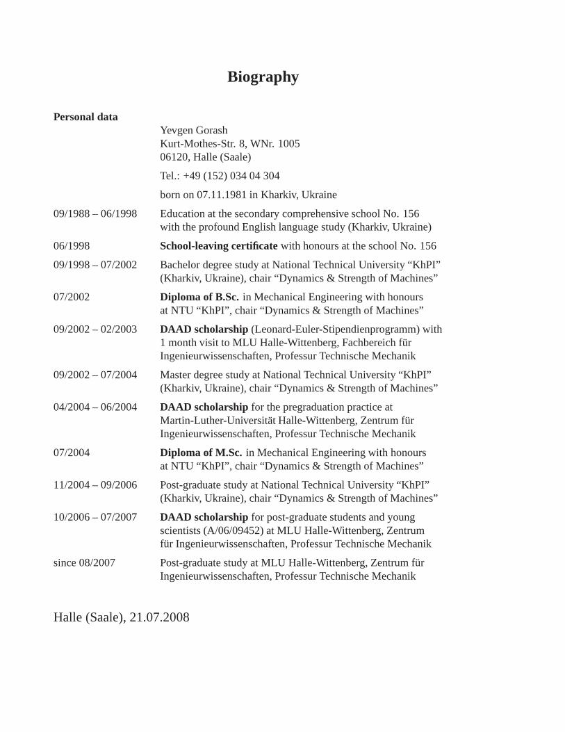
Biography
Personal dataYevgen GorashKurt-Mothes-Str. 8, WNr. 100506120, Halle (Saale)
Tel.: +49 (152) 034 04 304
born on 07.11.1981 in Kharkiv, Ukraine
09/1988 – 06/1998 Education at the secondary comprehensiveschool No. 156with the profound English language study (Kharkiv, Ukraine)
06/1998 School-leaving certificatewith honours at the school No. 156
09/1998 – 07/2002 Bachelor degree study at National Technical University “KhPI”(Kharkiv, Ukraine), chair “Dynamics & Strength of Machines”
07/2002 Diploma of B.Sc. in Mechanical Engineering with honoursat NTU “KhPI”, chair “Dynamics & Strength of Machines”
09/2002 – 02/2003 DAAD scholarship (Leonard-Euler-Stipendienprogramm) with1 month visit to MLU Halle-Wittenberg, Fachbereich furIngenieurwissenschaften, Professur Technische Mechanik
09/2002 – 07/2004 Master degree study at National TechnicalUniversity “KhPI”(Kharkiv, Ukraine), chair “Dynamics & Strength of Machines”
04/2004 – 06/2004 DAAD scholarship for the pregraduation practice atMartin-Luther-Universitat Halle-Wittenberg, Zentrum furIngenieurwissenschaften, Professur Technische Mechanik
07/2004 Diploma of M.Sc. in Mechanical Engineering with honoursat NTU “KhPI”, chair “Dynamics & Strength of Machines”
11/2004 – 09/2006 Post-graduate study at National Technical University “KhPI”(Kharkiv, Ukraine), chair “Dynamics & Strength of Machines”
10/2006 – 07/2007 DAAD scholarship for post-graduate students and youngscientists (A/06/09452) at MLU Halle-Wittenberg, Zentrumfur Ingenieurwissenschaften, Professur Technische Mechanik
since 08/2007 Post-graduate study at MLU Halle-Wittenberg, Zentrum furIngenieurwissenschaften, Professur Technische Mechanik
Halle (Saale), 21.07.2008
Related Documents


