Preliminary version 1.0 www.TechToys.com.hk TechToys Company 1 Development board for PIC16F690 and Nordic RF modules

Welcome message from author
This document is posted to help you gain knowledge. Please leave a comment to let me know what you think about it! Share it to your friends and learn new things together.
Transcript
Preliminary version 1.0 www.TechToys.com.hk TechToys Company
1
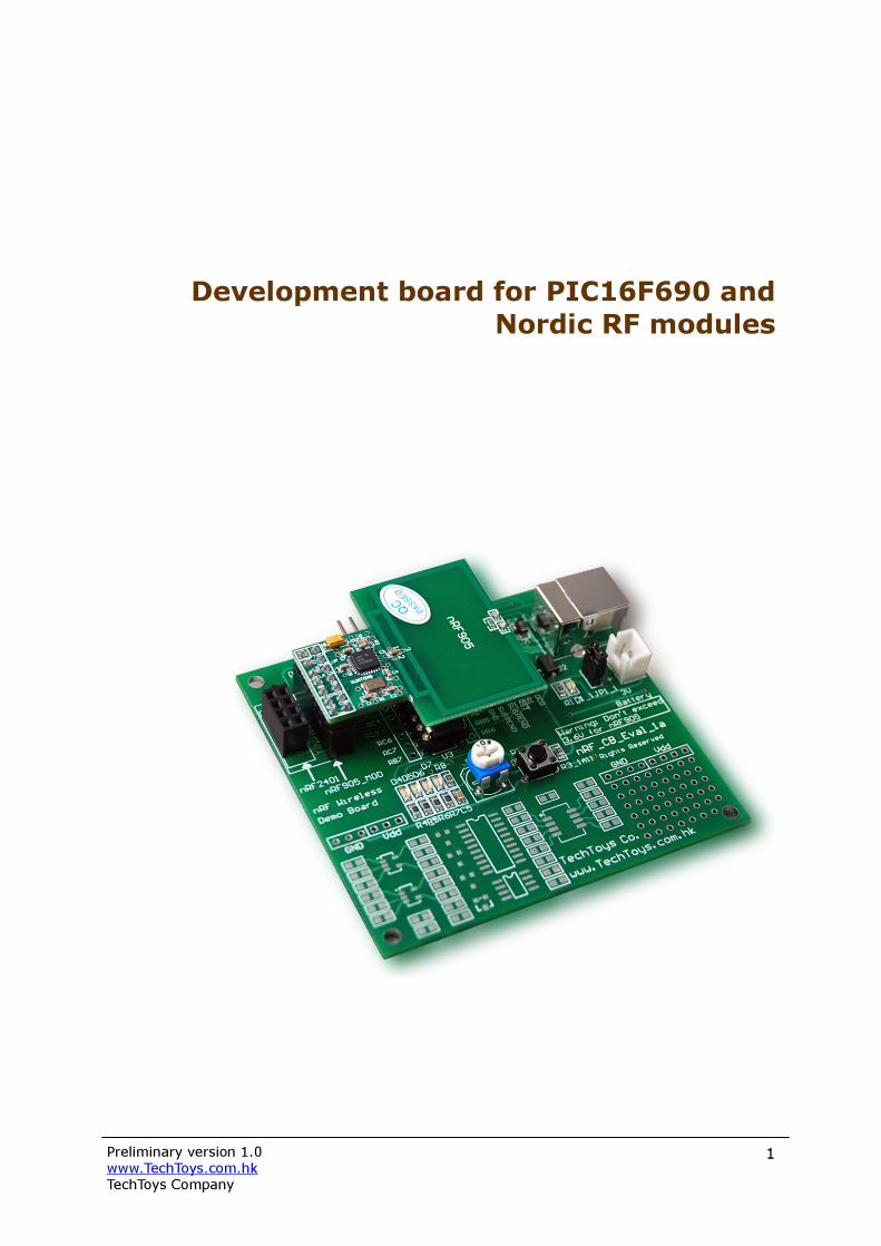
Development board for PIC16F690 and Nordic RF modules
Preliminary version 1.0 www.TechToys.com.hk TechToys Company
2
INTRODUCTION The development board for PIC16F690 (part# nRF_CB_Eval_1a) is an evaluation platform for low pin count 8-bit microcontrollers from Microchip, plus the special features of an integrated CP2102 USB-to-UART bridge from Silicon Labs (www.silabs.com) and sockets for both Nordic nRF905 multi-band wireless module as well as a new 2.4GHz wireless module from us. The part number nRF_CB_Eval_1a includes one nRF905 wireless module as a standard package. DEVICES SUPPORTED BY THE nRF_CB_EVAL The following devices from Microchip would be supported. 8-pin DIP Flash Devices: PIC12F508 PIC12F629 PIC12F635 PIC12F509 PIC12F675 PIC12F683 PIC12F510 14-pin DIP Flash Devices: PIC16F505 PIC16F630 PIC16F684 PIC16F506 PIC16F676 PIC16F688 20-pin DIP Flash Devices: PIC16F685 PIC16F689 PIC16F785 PIC16F687 PIC16F690 A PIC16F690 is included with the board. The nRF_CB_Eval works with the PICKit 2 Microcontroller Programmer directly. An ICD2 cable is included in the package for direct connection with an ICD2 as well. PICKit 2 is a low cost device programmer manufactured by Microchip. One may refer to the PROGRAM SECTION on page 8 for further details. Every nRF_CB_Eval board will be preloaded with a demonstration program. To see the result of this program, simply connect a USB cable to a PC. There is nothing dealing with USB communication yet. The USB port is used for 5V power supply to the CP2102 onboard which includes an on-chip 5 to 3V voltage regulator. This allows the CP2102 to be configured as a USB bus-powered device. The maximum regulator supply current is 100mA. This is more than enough for our applications even for a wireless module firing signal at the highest power. For further information on the CP2102, please consult its data sheet from www.silabs.com. It is also possible to use the battery connector for mobile applications. However, please make sure that only 2x 1.5V batteries are used when Nordic wireless module is in place. The maximum voltage for nRF905 and nRF2401 wireless modules is 3.6V.

Preliminary version 1.0 www.TechToys.com.hk TechToys Company
3
FEATURES
Function Designator 1 Microcontroller – it is the heart of the board.
PIC16F690 is included with every board. U3
2 CP2102 USB-to-UART bridge converts USB data to UART format without handling the USB software layer. This allows us to use UART programs for microcontrollers on a PC’s USB port. On-chip 5 to 3V regulator is configured as a USB bus-powered device.
U1
3 2x1.5V battery socket with enable jumper JP1 for mobile applications.
3V Battery & JP1 4 ICSP connector directly compatible with Microchip PICKit2
programmer. Triangular mark 1 indicates the MCLR pin of U3. An RJ12 to 6-pin 2.54mm cable is included for ICD2 connection.
ICSP
5 2.54mm 2x7 box header for Nordic nRF905 433/866MHz wireless module. Square pad indicates pin 1.
nRF905_MOD 6 2.54mm 2x4 box header for Nordic nRF2401 2.4GHz wireless
module. Square pad indicates pin 1. nRF2401
7 LED D4 to D7 connected to RC0 to RC3 D4-D7 8 10k trimmer for ADC experiments RA0 9 Tact switch for RESET or general purpose IO. Software
selectable. RESET
10 SMT and DIP prototype areas NA

Preliminary version 1.0 www.TechToys.com.hk TechToys Company
4
nRF_CB_Eval is compatible with all applications designed for LOW PIN COUNT DEMO BOARD manufactured by Microchip. There are 12 lessons provided by Microchip beginning with Hello World application to Look-up Table all designed in assembly language. One may download all of them at http://www.microchip.com/stellent/idcplg?IdcService=SS_GET_PAGE&nodeId=1406&dDocName=en023805 under the title of PICKit2 Starter Kit Lessons. On top of the PICKit 2 starter Kit Lessons, there are several examples on CP2102 and Nordic nRF905 RF module. The programming language is PICC-Lite developed by Hi-Tech software (www.htsoft.com). ABOUT PICC-Lite COMPILER PICC-Lite is a C compiler developed by Hi-Tech Software. Visiting the company web site of Hi-Tech Software you will find it not only develops C complier for Microchip, it also does compilers for most of the other microcontrollers in the market. Under the download section you will find HI-TECH PICC-LITE v9.60 as the Free Software without any expiry date. Click the link below to see a full description of the compiler and its limitation. http://www.htsoft.com/products/compilers/PICC-Lite.php For PIC16F690, we have 2K program memory supported with 2 RAM banks. It may not be enough for a professional money-earning project but it would be alright for demonstration purpose. Download the package and get it installed by accepting the default directory. By accepting the default installation path, you will get a bin directory under the folder C:\Program Files\HI-TECH Software\PICC\lite\9.60\. This bin folder contains the execute file. Besides, there is a sample folder with several examples. We will use some of them in forth coming projects.
Preliminary version 1.0 www.TechToys.com.hk TechToys Company
5
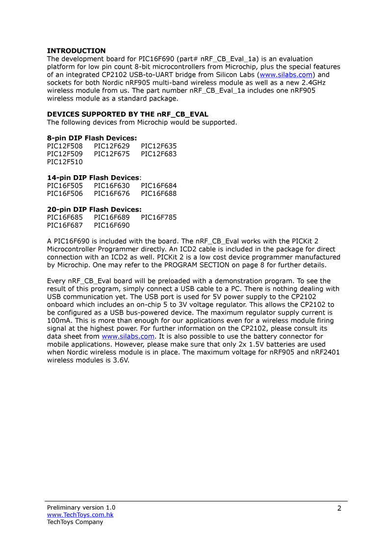
It is assumed that MPLAB version 7.50 or later has been installed in your development workstation. To integrate PICC-Lite with MPLAB, first create a new project under Project→New…in MPLAB. A New Project window will pop up with Project Directory and Project Name information that you need to fill in. Just create a directory of your convenience (my case being D:\Microchip\PICC-Lite\HelloWorld) and the first project being the HelloWorld as the Project Name. From Configure→Select Device… menu of the MPLAB, select 16F690 as the microcontroller to use. Click OK.

Preliminary version 1.0 www.TechToys.com.hk TechToys Company
6
Click Project→Select Language Toolsuite…to bring up the following dialog box. In the Active Toolsuite drop down manual select HI-TECH Universal ToolSuite and then browse to the .\PICC\lite\9.60\bin\picl.exe file under the Location text box. The execute file picl.exe is the compiler that we need. Click OK to exit. All we have to do now is to create a new document and type in a simple LED blinking program as the HelloWorld project. Under File, click on New. A new document will be created with an empty template. Type in the following code and then save it as main.c under the project folder. Right click on Source Files at the project workspace at the left Panel and add main.c to the Source Files. That is all we need! Under Project, press Build to compile this simple program.
#include <htc.h> main(void) {
; }

Preliminary version 1.0 www.TechToys.com.hk TechToys Company
7
The Output Window shows that we have at least successfully compiled a program, even though this program will not do anything yet! Browse to the project folder you will see there is a HelloWorld.hex file created. This is the hex file we need to download to 16F690 to build an embedded system. Before going deeper, let’s investigate the content of the header file <htc.h> included in the first statement. Browse to the installation directory of PICC-Lite under .\PICC\lite\9.60\include, there is the htc.h file. This is the header file for all compilers developed by HI-TECH Software, which in turns includes another header file pic.h for our case (PICC-Lite). Inside pic.h, there are header files of all devices supported by PICC compiler which are not only for the lite version but also for the full version of price US$950. Inside pic.h we have the following directive language: #if defined(_16F631) || defined(_16F677) || defined(_16F685) ||\ defined(_16F687) || defined(_16F689) || defined(_16F690) #include <pic16f685.h> #endif Under Configure→Select Device… we have already selected 16F690 as the target device thus we have satisfied the condition above _16F690. As a result, the header file pic16f685.h has been included implicitly to define all relevant register definitions of the PIC16F631, 677, 685, 687, 689, and 690 family. That is also why we did not need to include 16F690.h header file (there is no such file either). The family is represented by the header file 16F685.h and it has been included by htc.h as a whole. Read briefly pic16f685.h we know direction pins and IO pins are represented as TRISX and RX. For port C, direction definition will be TRISCx, and RCx. If we want to use RC0 which is wired to LED D4 on our hardware, we need to configure TRISC0 and RC0. We may switch on the LED D4 by the following code: The code is self-explanatory. Compile this code to obtain a hex file found under the same project directory. Here we come to the step to program this hex file.
#include <htc.h> main() { TRISC0 = 0; //configure RC0 as an output RC0 = 1; //output high for RC0 while (1) ; //trap the program here as an infinite loop }
Preliminary version 1.0 www.TechToys.com.hk TechToys Company
8
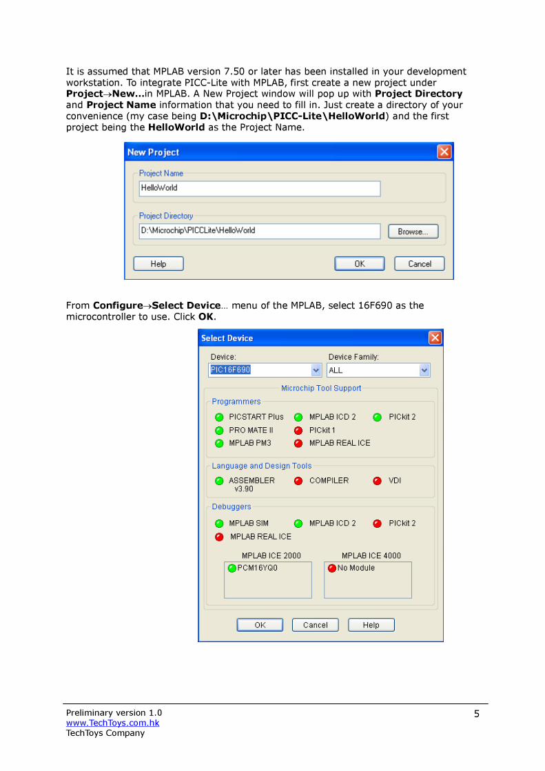
PROGRAM SECTION - ICD2 operation The first choice is to use an ICD2 if you have one. Use the ICD2 cable supplied with the package and match the embossed triangular mark of the 2.54mm 6 pins header with the white triangular mark 1 on board as shown below. This is the MCLR pin. In MPLAB select ICD2 under the Programmer menu. One must notice the difference between using an ICD2 with a PICKit2 programmer. PICKit2 requires a voltage of 4.5V minimum for programming because of the Bulk Erase Programming method used in PICKit2. However, there is no such restriction with ICD2. As a result, it is possible to have the nRF905 module safely plug in the socket for in-circuit serial programming since the whole system would be powered by 3.0V from internal regulator of CP2102. However, it is mandatory to use another USB cable for supplying USB bus power to CP2102 which converts 5V to 3V for the whole system when ICD2 is used. Finally click program under the Programmer menu to finish the job.
Preliminary version 1.0 www.TechToys.com.hk TechToys Company
9
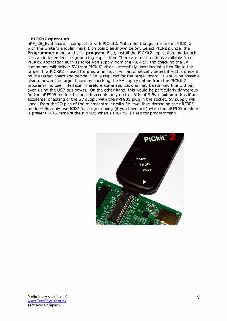
- PICKit2 operation nRF_CB_Eval board is compatible with PICKit2. Match the triangular mark on PICKit2 with the white triangular mark 1 on board as shown below. Select PICKit2 under the Programmer menu and click program. Else, install the PICKit2 application and launch it as an independent programming application. There are more options available from PICKit2 application such as force Vdd supply from the PICKit2, and checking the 5V combo box will deliver 5V from PICKit2 after successfully downloaded a hex file to the target. If a PICKit2 is used for programming, it will automatically detect if Vdd is present on the target board and decide if 5V is required for the target board. It would be possible also to power the target board by checking the 5V supply option from the PICKit 2 programming user interface. Therefore some applications may be running fine without even using the USB bus power. On the other hand, this would be particularly dangerous for the nRF905 module because it accepts only up to a Vdd of 3.6V maximum thus if an accidental checking of the 5V supply with the nRF905 plug in the socket, 5V supply will sneak from the IO pins of the microcontroller with 5V level thus damaging the nRF905 module! So, only use ICD2 for programming (if you have one) when the nRF905 module is present –OR- remove the nRF905 when a PICKit2 is used for programming.
Preliminary version 1.0 www.TechToys.com.hk TechToys Company
10
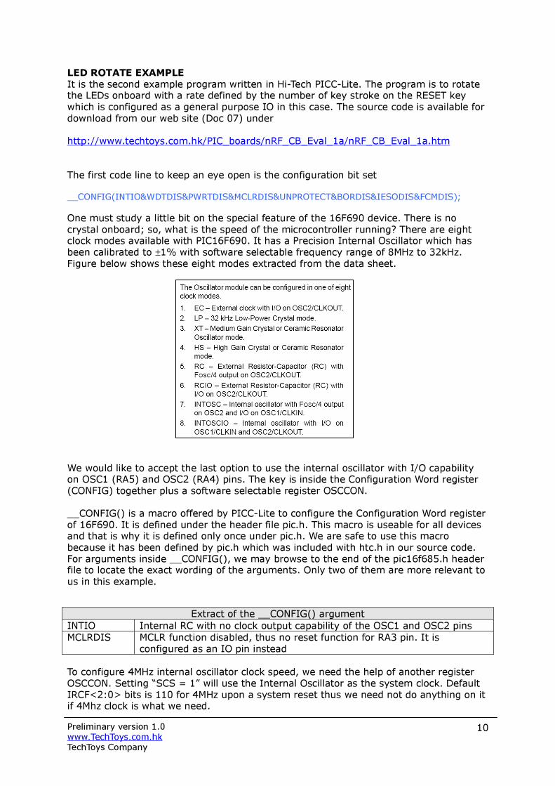
LED ROTATE EXAMPLE It is the second example program written in Hi-Tech PICC-Lite. The program is to rotate the LEDs onboard with a rate defined by the number of key stroke on the RESET key which is configured as a general purpose IO in this case. The source code is available for download from our web site (Doc 07) under http://www.techtoys.com.hk/PIC_boards/nRF_CB_Eval_1a/nRF_CB_Eval_1a.htm The first code line to keep an eye open is the configuration bit set __CONFIG(INTIO&WDTDIS&PWRTDIS&MCLRDIS&UNPROTECT&BORDIS&IESODIS&FCMDIS); One must study a little bit on the special feature of the 16F690 device. There is no crystal onboard; so, what is the speed of the microcontroller running? There are eight clock modes available with PIC16F690. It has a Precision Internal Oscillator which has been calibrated to ±1% with software selectable frequency range of 8MHz to 32kHz. Figure below shows these eight modes extracted from the data sheet. We would like to accept the last option to use the internal oscillator with I/O capability on OSC1 (RA5) and OSC2 (RA4) pins. The key is inside the Configuration Word register (CONFIG) together plus a software selectable register OSCCON. __CONFIG() is a macro offered by PICC-Lite to configure the Configuration Word register of 16F690. It is defined under the header file pic.h. This macro is useable for all devices and that is why it is defined only once under pic.h. We are safe to use this macro because it has been defined by pic.h which was included with htc.h in our source code. For arguments inside __CONFIG(), we may browse to the end of the pic16f685.h header file to locate the exact wording of the arguments. Only two of them are more relevant to us in this example.
Extract of the __CONFIG() argument INTIO Internal RC with no clock output capability of the OSC1 and OSC2 pins MCLRDIS MCLR function disabled, thus no reset function for RA3 pin. It is
configured as an IO pin instead To configure 4MHz internal oscillator clock speed, we need the help of another register OSCCON. Setting “SCS = 1” will use the Internal Oscillator as the system clock. Default IRCF<2:0> bits is 110 for 4MHz upon a system reset thus we need not do anything on it if 4Mhz clock is what we need.
Preliminary version 1.0 www.TechToys.com.hk TechToys Company
11
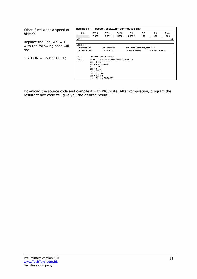
What if we want a speed of 8MHz? Replace the line SCS = 1 with the following code will do: OSCCON = 0b01110001; Download the source code and compile it with PICC-Lite. After compilation, program the resultant hex code will give you the desired result.

Preliminary version 1.0 www.TechToys.com.hk TechToys Company
12
UART EXAMPLE WITH CP2102 First of all, we need to install the Virtual COM PORT driver from Silicon Labs at http://www.silabs.com/tgwWebApp/public/web_content/products/Microcontrollers/Interface/en/interface.htm. Some PCs and notebook computers nowadays may not come with a COM PORT anymore. Unfortunately, serial communication in UART is still common on microcontrollers. We need a device to convert data between USB and UART formats for small microcontrollers. There are various solutions offered by a number of chip vendors like FTDI. However, because FTDI is not popular in my place so an alternative offered by Silicon Labs has been employed. One may find more information about using USB with the simplicity of RS-232 from Beyond Logic at http://www.beyondlogic.org/usb/ftdi.htm. The CP2102 is a highly-integrated USB-to-UART bridge controller providing a simple solution for upgrading RS-232 designs to USB using just a few additional capacitors and resistors. With a Virtual COM PORT driver installed, a PC will be installed with a COM PORT emulated by the driver as shown with the screen shot below. Once we have got a COM PORT emulated under the Device Manager, we would be able to use serial communication programs such as HyperTerminal or Docklight (www.docklight.de) on PCs without an actual COM PORT. Personally I prefer Docklight because it offers much more flexibility. Listing below shows the demonstration code for UART demonstration. #include <stdio.h> (1) #include <htc.h> #include "uart.h" (2) __CONFIG(INTIO&WDTDIS&PWRTDIS&MCLREN&UNPROTECT&BORDIS&IESODIS&FCMDIS); (3) void main(void) {
unsigned char input; ANSEL = 0x00; (4) ANSELH = 0x00; (5) SCS = 1; (6) INTCON = 0; (7) init_comms(); (8) printf("\rPress a key and I will echo it back:\n"); (9) while(1)
{ input = getch(); (10) printf("\rI detected [%c]",input); (11) } }
Preliminary version 1.0 www.TechToys.com.hk TechToys Company
13
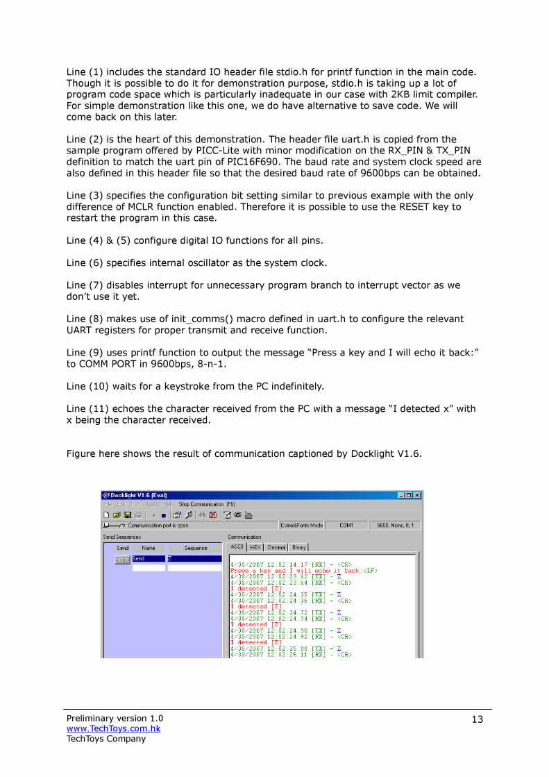
Line (1) includes the standard IO header file stdio.h for printf function in the main code. Though it is possible to do it for demonstration purpose, stdio.h is taking up a lot of program code space which is particularly inadequate in our case with 2KB limit compiler. For simple demonstration like this one, we do have alternative to save code. We will come back on this later. Line (2) is the heart of this demonstration. The header file uart.h is copied from the sample program offered by PICC-Lite with minor modification on the RX_PIN & TX_PIN definition to match the uart pin of PIC16F690. The baud rate and system clock speed are also defined in this header file so that the desired baud rate of 9600bps can be obtained. Line (3) specifies the configuration bit setting similar to previous example with the only difference of MCLR function enabled. Therefore it is possible to use the RESET key to restart the program in this case. Line (4) & (5) configure digital IO functions for all pins. Line (6) specifies internal oscillator as the system clock. Line (7) disables interrupt for unnecessary program branch to interrupt vector as we don’t use it yet. Line (8) makes use of init_comms() macro defined in uart.h to configure the relevant UART registers for proper transmit and receive function. Line (9) uses printf function to output the message “Press a key and I will echo it back:” to COMM PORT in 9600bps, 8-n-1. Line (10) waits for a keystroke from the PC indefinitely. Line (11) echoes the character received from the PC with a message “I detected x” with x being the character received. Figure here shows the result of communication captioned by Docklight V1.6.
Preliminary version 1.0 www.TechToys.com.hk TechToys Company
14
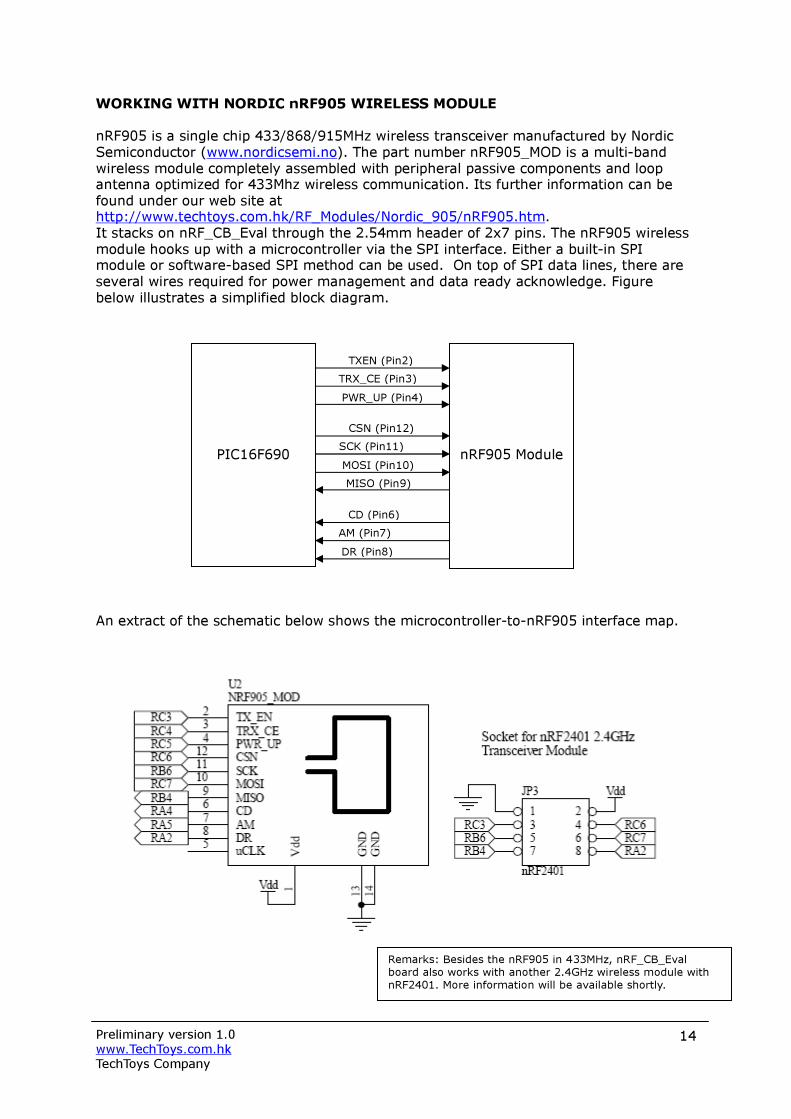
WORKING WITH NORDIC nRF905 WIRELESS MODULE nRF905 is a single chip 433/868/915MHz wireless transceiver manufactured by Nordic Semiconductor (www.nordicsemi.no). The part number nRF905_MOD is a multi-band wireless module completely assembled with peripheral passive components and loop antenna optimized for 433Mhz wireless communication. Its further information can be found under our web site at http://www.techtoys.com.hk/RF_Modules/Nordic_905/nRF905.htm. It stacks on nRF_CB_Eval through the 2.54mm header of 2x7 pins. The nRF905 wireless module hooks up with a microcontroller via the SPI interface. Either a built-in SPI module or software-based SPI method can be used. On top of SPI data lines, there are several wires required for power management and data ready acknowledge. Figure below illustrates a simplified block diagram. An extract of the schematic below shows the microcontroller-to-nRF905 interface map.
PIC16F690
nRF905 Module
TXEN (Pin2) TRX_CE (Pin3) PWR_UP (Pin4)
CSN (Pin12) SCK (Pin11) MOSI (Pin10) MISO (Pin9)
CD (Pin6) AM (Pin7) DR (Pin8)
Remarks: Besides the nRF905 in 433MHz, nRF_CB_Eval board also works with another 2.4GHz wireless module with nRF2401. More information will be available shortly.

Preliminary version 1.0 www.TechToys.com.hk TechToys Company
15
A practical scenario of a multi-node wireless communication environment illustrated below: Data Packet Transmission (ShockBurst TX)
1. When the PC has data for remote node Slave 1, the address of Slave 1 and data are sent from the PC to the mcu. Registers for address is called TX_ADDRESS (1-4 bytes), and the registers for data are TX_PAYLOAD which is software configurable from 1-32 bytes. The mcu interprets this data packet and get nRF905 prepared for transmission by bringing PWR_UP and TX_EN high while keeping TRX_CE low to put it in Standby Mode. Data packet is clocked into nRF905_MOD via SPI interface by setting CSN low to “chip enable” and it is clocked (SCK) into the nRF905 silicon via the MOSI pin.
2. After step 1, we have the address(TX-address) and data (TX-payload) stored inside the corresponding registers of nRF905. A low-high-low pulse of 10µs minimum1 on TRX_CE pin is required to turn on the nRF905 transmission mode (Nordic calls it ShockBurst transmission).
3. nRF905 is powered up with preamble and CRC calculated by hardware. No software from the mcu is required. Then the data packet is transmitted automatically. Data Ready (DR) pin is set high when transmission is completed. The mcu can be configured to detect the DR pin by interrupt so there is no mcu polling time.
1 There is an alternative to keep TRX_CE high instead of a low-high-low pulse for single shoot transmission if continuously retransmission of the package is preferred. If TX_EN is kept low while keeping the TRX_CE high, nRF905 then enters receive mode after finished transmitting. Please refer to nRF905 Product Specification for details.
mcu nRF905_MOD
Slave 1
mcu nRF905_MOD
Slave 2
mcu nRF905_MOD
Master
PC

Preliminary version 1.0 www.TechToys.com.hk TechToys Company
16
Data Packet Receive (ShockBurst RX) 1. ShockBurst Rx is selected by setting PWR_UP high, TRX_CE high, and TX_EN low.
This prepares nR905 for continuously monitoring the air for incoming communication. The current consumption for this RX mode reaches an ample amount of 12mA, which is a lot for battery operation. A rechargeable AA battery normally has a capacity of 2,000mAh. That means a continuous RX operation of 166.66 hours in an ideal situation (2,000mAh/12mA). There is a reduced power mode to reduce the sensitivity; however, the penalty is a degraded signal detection performance with only a slight reduction from 12mA to 10mA of consumption. The solution for this may be periodic wake up on the nRF905 module from power down mode for a short period of time, say 1ms in every 1 second if the gap between data transmission is known and there is a good data handshake protocol.
2. When the nRF905 senses a carrier at the receiving frequency configured in the CH_NO and HFREQ_PLL registers (i.e. the fRF), the Carrier Detect (CD) pin will be set high. The air is full of ambient RF waves of different frequencies however. Therefore this pin only is not enough for detection of a valid data packet.
3. When a valid address (for Slave 1 in our discussion) is received, the Address Match (AM) pin is set high. You may imagine Slave 2 is also monitoring the air for the same carrier frequency but the AM pin is not set because the data packet is not for Slave 2. Silicon of both Slave 1 and Slave 2 checks continuously for an address match and set its AM pin when there is a match.
4. Here it comes the data integrity. When a valid packet has been received with the correct CRC found, nRF905 will remove the preamble, address, and CRC bits by hardware. No mcu software required! Then the Data Ready (DR) pin is set high to notify the mcu for a successful data packet.
5. It is up to the designer to set the TRX_CE pin low to put nRF905 to low current Standby mode (12-46µA, depends on crystal frequency) or stay at the ShockBurst RX mode for continuous monitoring.
6. Data packet is stored in the RX data registers (Nordic gave it the name of RX PAYLOAD). Its size is software configurable for a size of 1-32 bytes. It is up to the designer when to retrieve from the RX_PAYLOAD. When all payload data has been retrieved, Data Ready (DR) and Address Match (AM) are set low again for the next data packet.
There are two example programs available from us. The driver is still under development therefore the current version is a preliminary one; but it is enough for demonstration. These are nRF905 Tx demo and nRF905 Rx demo for transmit and receive functions respectively. The codes are heavily commented so anyone would be able to understand.
------------ to be continued with separate application notes ------------
Related Documents