General rights Copyright and moral rights for the publications made accessible in the public portal are retained by the authors and/or other copyright owners and it is a condition of accessing publications that users recognise and abide by the legal requirements associated with these rights. Users may download and print one copy of any publication from the public portal for the purpose of private study or research. You may not further distribute the material or use it for any profit-making activity or commercial gain You may freely distribute the URL identifying the publication in the public portal If you believe that this document breaches copyright please contact us providing details, and we will remove access to the work immediately and investigate your claim. Downloaded from orbit.dtu.dk on: Jul 17, 2022 Developing high performance and climatically reliable Hearing Aids Yadav, Abhijeet Publication date: 2021 Document Version Publisher's PDF, also known as Version of record Link back to DTU Orbit Citation (APA): Yadav, A. (2021). Developing high performance and climatically reliable Hearing Aids. Technical University of Denmark.

Welcome message from author
This document is posted to help you gain knowledge. Please leave a comment to let me know what you think about it! Share it to your friends and learn new things together.
Transcript
General rights Copyright and moral rights for the publications made accessible in the public portal are retained by the authors and/or other copyright owners and it is a condition of accessing publications that users recognise and abide by the legal requirements associated with these rights.
Users may download and print one copy of any publication from the public portal for the purpose of private study or research.
You may not further distribute the material or use it for any profit-making activity or commercial gain
You may freely distribute the URL identifying the publication in the public portal If you believe that this document breaches copyright please contact us providing details, and we will remove access to the work immediately and investigate your claim.
Downloaded from orbit.dtu.dk on: Jul 17, 2022
Developing high performance and climatically reliable Hearing Aids
Yadav, Abhijeet
Publication date:2021
Document VersionPublisher's PDF, also known as Version of record
Link back to DTU Orbit
Citation (APA):Yadav, A. (2021). Developing high performance and climatically reliable Hearing Aids. Technical University ofDenmark.

Developing high performance and climatically reliable Hearing Aids Abhijeet Yadav
PhD Thesis
DTU Mechanical EngineeringDepartment of Mechanical Engineering
Developing high performance and climatically
reliable Hearing Aids
PhD Thesis
June, 2021
by
Abhijeet Yadav
Supervisors:
Prof. Rajan Ambat
Christian Espersen
Section of Materials and Surface Engineering
Department of Mechanical Engineering
Technical University of Denmark (DTU)
Produktionstorvet, building. 425
DK-2800, Kongens Lyngby, Denmark

”Arise! Awake! and stop not until the goal is reached.”
~ Swami Vivekananda ~
This thesis is dedicated to my parents
i
Preface
This thesis is submitted in candidacy for a PhD degree from the Technical University of Denmark. The
project entitled “Developing high performance and climatically reliable Hearing Aids” was carried out
at the Department of Mechanical Engineering, Section of Materials and Surface Engineering in
collaboration with Widex A/S, during the period from March 1st, 2018 until June 30th, 2021. The project
is a part of the Industrial PhD program, funded and supported by Innovation Fund Denmark, grant
number 7038-00120B. Prof. Rajan Ambat from the Technical University of Denmark, Department of
Mechanical Engineering, and Christian Bohl Espersen from R&D, Widex A/S, supervised the project.
ii
Acknowledgements
First, I would like to acknowledge my supervisors Prof. Rajan Ambat and Christian Bohl Espersen for
giving me this opportunity to work on this innovative research project and for their invaluable
guidance, advice and support during the project. I express my deep appreciation for their dedication,
and enthusiasm to bring research and industry together to cultivate knowledge and technology for
the benefit of larger society. Also, Innovation Fund Denmark and Widex A/S are acknowledged for the
funding and overall support of the PhD program.
I also would like to thank all my colleagues from the Celcorr/Crecon group, section of Materials and
Surface Engineering at DTU for providing pleasant working environment. Special thanks to Morten
Stendahl Jellesen and Peter Westermann for their help and support during lab experiments.
Many thanks to colleques from Widex A/S, especially from Quality Control and Basic Concept
Development (BCD) teams for their help, support and guidance during the PhD. My personal thanks
to Lars Baekgaard, Morten Loegstrup, Villy Jensen and Frank Kesby Laursen for their support and time
in conducting experiments and their analysis.
Last but not the least I would like to thank my family, my friends, and especially my lovely wife Komal
for her unconditional love, sacrifice and support in the completion of this project. My most special
thanks goes to my nephew Abhiveer for bringing smile on my face even during the worst days.
iii
Abstract
This PhD project is the outcome of collaboration between Celcorr (Centre for electronics corrosion)
research group at DTU and Widex A/S (hearing aid manufacturer) as a part of Industrial PhD,
supported by Innovation Fund Denmark. The project is motivated by the need to understand the effect
of climatic conditions and contamination on the corrosion-related failures and overall climatic
reliability of hearing aids. Hearing aids are miniature size devices and during operation, are subjected
to various levels of corrosive contamination from the atmosphere and human body along with varying
temperature and humidity conditions. All these factors are known for causing failures in electronic
devices and their components in the form of SIR reduction, ECM migration and many more. The part
of the research conducted in this thesis focuses on developing a detailed understanding of various
failure modes, mechanism and its causes through root cause failure analysis of failed hearing aids from
different markets throughout the globe. The comprehensive knowledge acquired from field failure
analysis of hearing aids was used to further investigate factors causing the corrosion, development of
test methods to replicate field failures, and finding optimum corrosion protection strategy for hearing
aid devices. The project's overall aim is to develop a more robust strategy for hearing aids in terms of
humidity-related issues based on indepth understanding of the failure mechanisms and various factors
involved.
Chapter 1 introduces the climatic reliability issues related to hearing aid devices and presents the
motivation behind the current PhD project. Chapter 2 provides a comprehensive literature review
discussion on the potential factors causing the formation of a water layer on the PCBA (print circuit
board assembly) surface and its influence on corrosion reliability of electronics. Furthermore, different
types of device and component level test methods used for reliability evaluation of electronics were
presented and finally the detail discussion on the corrosion protection of electronics by conformal
coating is discussed. A short summary of the literature review and overall objective of the thesis is
provided at the end of the literature review.The test results comprise of three appended papers
(submitted to an international journal) and two research chapters.
Chapter 3 and 4 (paper 1 and 2) constitutes the statistical and root cause failure analysis of hearing
aid devices from tropical, Europe, USA and Japan markets. The result consists of detailed information
about the failure mechanisms and its causes for different device components. The most prominent
failure cause was potassium hydroxide (KOH) residues coming from the leakage of Zn-air batteries
(ZAB’s), which are used as a power source for hearing aids. Therefore, subsequent chapter 5 (paper 3)
focuses on investigating the synergetic effect of temperature, humidity and exposure duration on the
rate of electrolyte leakage from ZAB’s. Chapter 6 presents different corrosion test methodology and
setup developed for mimicking the failures from the field and implementation of the acceleration
factors in the tests that were identified from the field failure investigation conducted in chapters 3
and 4. Final chapter 7 investigates the performance of different potential conformal coating
candidates under exposure to simulated field climatic conditions and KOH contamination.
Overall, a high amount of corrosion was observed in all the field-failed devices across different
markets. Microphones showed the highest failure percentage among all the hearing aid components,
while other components like hand solderings, battery contacts, and LED showed high susceptibility
and failure probability due to corrosion. The failure cause in the tropical region was dominated by the
leakage of electrolyte from ZAB, whereas failures from Europe, USA and Japan markets were
dominated due to high amount of sweat and salt ingress into the device.

iv
The leakage of ZAB is influenced by climatic factors (high temperature and humidity) and the duration
of its exposure to the conditions. Among the various hearing aid batteries tested, the temperature
effect had a more pronounced impact on the amount of KOH released from the batteries. KOH
residues showed a very high hygroscopic behavior with deliquescence occurrence at ~ 50% relative
humidity (RH) and its impact on the corrosion failure of electronics was evaluated by electrochemical
impedance spectroscopy analysis using interdigitated pattern (SIR comb pattern).
Finally, the performance of different conformal coatings as a corrosion protection strategy was
evaluated using a Test PCBA board. Test methods consisting of EIS and DC leak current test using a
conformal coated interdigitated pattern on the Test board under exposure to climatic cycle
(humidity/temperature cycle) and KOH contamination were used for the study. Among all the
coatings, acrylate polyurethane-type conformal coatings showed the most promising results with
good adhesion and high resistance to water absorption and degradation due to KOH contamination.
Overall outcome from the work is discussed in chapter 8, and major conclusions are listed in chapter
9 along with future perspectives.
v
Dansk Resumé
Dette ph.d.-projekt er resultatet af et samarbejde mellem Celcorr (Center for korrosion i elektronik)
forskergruppe ved DTU og Widex A/S (høreapparatproducent) som en del af Erhvervs ph.d. projekt,
støttet af Innovationsfonden. Projektet er motiveret af behovet for at forstå effekten af klimatiske
forhold og forurening på korrosionsrelaterede fejl og den samlede klimatiske pålidelighed af
høreapparater. Høreapparater er miniature størrelse enheder og under drift udsættes for forskellige
niveauer af kontaminering fra atmosfære og menneskekroppe der sammen med varierende
temperatur- og fugtighedsforhold kan resulterer i korrosion. Sådanne faktorer er kendt for at kunne
forårsage fejl i elektroniske enheder og deres komponenter i form af lækstrøm, elektrokemisk
migraion og mange typer af fejlmekanismer. Denne afhandling fokuserer på at udvikle en detaljeret
forståelse af forskellige fejlstilstande, mekanismer og årsager gennem fejlanalyse af høreapparater fra
forskellige internationale markeder. Den omfattende viden fra fejlanalyse af høreapparater blev brugt
til at undersøge faktorer, der forårsagede korrosion, udvikling af testmetoder til at replikere fejl og
finde en optimal korrosionsbeskyttelsesstrategi for høreapparatudstyr. Projektets overordnede mål
er at udvikle en mere robust strategi for høreapparater med hensyn til fugtrelaterede problemer
baseret på en dybtgående forståelse af fejlmekanismerne og forskellige involverede faktorer.
Kapitel 1 introducerer de klimatiske pålidelighedsproblemer i forbindelse me d høreapparatudstyr og
præsenterer motivationen bag dette ph.d.-projekt. Kapitel 2 indeholder en omfattende
litteraturgennemgang om de potentielle faktorer, der forårsager dannelsen af et vandlag på printkort
og hvilken indflydelse det har på korrosionspålideligheden af elektronik. Derudover blev forskellige
typer testmetoder anvendt til pålidelighedsevaluering af elektronik præsenteret, og endelig
diskuteres korrosionsbeskyttelse af elektronik ved hjælp af beskyttende lak systemer. En kort oversigt
over litteraturgennemgangen og det overordnede mål for afhandlingen gives i slutningen af
litteraturgennemgangen. Testresultaterne fremgår af tre vedlagte artikler (indsendt til international
tidsskrifter) og to kapitler.
Kapitel 3 og 4 (artikel 1 og 2) udgør den statistiske analyse og fejlanalyse af høreapparater fra det
tropiske marked, Europa, USA og Japan. Resultaterne består af detaljerede oplysninger om
fejlmekanismen og dens årsager for forskellige komponenter. Den mest fremtrædende fejlårsag var
rester af kaliumhydroxid (KOH), der kommer fra lækage af zink-luft batterier, som bruges som
strømkilde til høreapparater. Derfor fokuserer efterfølgende kapitel 5 (artikel 3) på at undersøge den
synergi virkning af temperatur, fugtighed og eksponeringsvarighed på hastigheden af elektrolytlækage
fra zink-luft batterier. Kapitel 6 præsenterer forskellige korrosionstestmetoder og opsætninger
udviklet til at imitere fejl fra brug og implementering af accelerationsfaktorer i test, der blev
identificeret fra fejlundersøgelsen udført i kapitel 3 og 4. Afsluttende kapitel 7 undersøger forskellige
lak systemer under eksponering for simulerede klimatiske forhold og KOH-forurening.
Samlet set blev der observeret en stor mængde korrosion i alle fejlede enheder på tværs af forskellige
markeder. Mikrofoner udviste den højeste fejlprocent blandt alle høreapparatkomponenterne, mens
andre komponenter som håndlodning, batterikontakter og LED komponenter viste høj modtagelighed
og fejlsandsynlighed på grund af korrosion. Fejlårsagen i det tropiske område var domineret af lækage
af elektrolyt fra zink-luft batterier, mens fejl fra markederne i Europa, USA og Japan var domineret af
en høj mængde sved og saltindtrængning.
Lækage af zink-luft batterier påvirkes af klimafaktorerne (høj temperatur og fugtighed) og varigheden
af dets eksponering for forholdene. Blandt de forskellige høreapparatbatterier, der blev testet, havde
temperatureffekten en mere markant effekt på mængden af KOH frigivet fra batterierne. KOH-rester
vi
viste en meget høj hygroskopisk adfærd med forekomst af fugtdannelse fra ~ 50% relativ fugtighed
(RH), og dens indvirkning på korrosion af elektronik blev evalueret ved elektrokemisk
impedansspektroskopi-analyse ved hjælp af interdigiterede mønstre (SIR-mønstre).
Desuden blev forskellige laksystemer tænkt som en korrosionsbeskyttelsesstrategi evalueret ved
hjælp af et test printkort. Testmetoder bestående af impedans og jævnstrøm under anvendelse af et
lak bleagt interdigiteret mønster eksponeret i en fugt ogtemperaturcyklus og KOH forurening blev
anvendt til undersøgelsen. Blandt alle laksystmer viste akrylat polyurethan de mest lovende resultater
med god vedhæftning og høj modstandsdygtighed over for vandabsorption og nedbrydning på grund
af KOH forurening.
Det samlede resultat fra arbejdet diskuteres i kapitel 8, og hovedkonklusioner er anført i kapitel 9
sammen med fremtidige perspektiver.
vii
List of abbreviations
HA Hearing Aid FPCB Flex Print Circuit Board PCBA Print Circuit Board Assembly CAF Cathodic Anodic Filament ECM Electrochemical Migration RH Relative Humidity cRH Critical Relative Humidity AH Absolute Humidity IC Integrated Circuit SEM Scanning Electron Microscope EDS Elemental Dispersive Spectroscopy SE Secondary Electron BSED Backscatter Electron Diffraction BET Brunauer Emmett Teller SIR Surface Insulation Resistance SMT Surface Mount Technology DRH Deliquescence Relative Humidity ERH Efflorescence Relative Humidity ENIG Electroless Nickel Immersion Gold PoF Physics of Failure CCT Cyclic Corrosion Test EIS Electrochemical impedance spectroscopy DC Direct Current AC Alternating Current SM Surface Mount ZAB Zinc-air Battery CC Conformal Coating Mic Microphone DPT Device Performance Test FPCBA Flex Print Circuit Board Assembly PCB Print Circuit Board Vol Volume Switch Rec Reciever Prog. Program Switch
viii
List of publication
Appended Papers
1. A. Yadav, K.K. Gupta, R. Ambat and M.L. Christensen, “Statistical analysis of corrosion failures in
hearing aid devices from tropical regions”, under revision in the journal for Engineering Failure
Analysis.
2. A. Yadav, K.K. Gupta, R. Ambat, C.B. Espersen, “A comparative study on corrosion failure analysis
of hearing aid devices from different markets”, draft to be submitted to Microelectronics
Reliability Journal.
3. J.M. Rao, A. Yadav, H.C. Gudla, R. Ambat, “Synergetic effect of temperature and humid conditions
on the leakage of KOH electrolyte from zinc-air batteries”, draft to be submitted to
Microelectronics Reliability Journal.
Conference Proceedings
1. A. Yadav, R. Ambat, “Corrosion induced failure mechanism of hearing aid electronic circuitry and
battery contacts”, 17th Nordic Corrosion Congress, Copenhagen, Denmark, 2018.
2. A. Yadav, R. Ambat, “Corrosion induced failure mechanism of hearing aid electronic circuitry and
battery contacts”, Proceedings of EUROCORR, Krakow, Poland, 2018.
3. A. Yadav, R. Ambat, “Corrosion induced failure mechanism of hearing aid electronic circuitry and
battery contacts”, European Symposium on Reliability of electronic Devices, Aalborg, Denmark,
2018.
4. A. Yadav, R. Ambat, “Test methods for understanding the corrosion mechanisms of hearing aids
subjected to high humidity and polluted environment”, Proceedings of EUROCORR, Seville, Spain,
2019.
5. A. Yadav, R. Ambat, “Comparative failure analysis of corrosion induced failure modes of hearing
aids from Asia, Europe and USA markets”, Proceedings of EUROCORR, online, 2020.
6. A. Yadav, “Performance evaluation of conformal coatings under cyclic climatic and field exposure
conditions”, SPM ERFA 6, Reliability, Copenhagen, 2021.

ix
Table of Contents
Chapter 1 Introduction ................................................................................................................. 1
1.1 Background ................................................................................................................... 1
1.2 Motivation and scope of the thesis ................................................................................. 3
1.3 Structure of the thesis.................................................................................................... 4
References................................................................................................................................... 6
Chapter 2 Literature Review ......................................................................................................... 8
2 Factors influencing climatic reliability of electronics .............................................................. 8
2.1 Humidity ....................................................................................................................... 9
2.1.1 Absolute humidity (AH) ........................................................................................... 9
2.1.2 Relative humidity (RH) ............................................................................................ 9
2.1.3 Dew Point (DP) ..................................................................................................... 10
2.2 Water layer formation on PCBA surface ........................................................................ 10
2.2.1 Effect of surface morphology of electronic components........................................... 12
2.3 Contamination............................................................................................................. 13
2.3.1 Solder flux residues ............................................................................................... 14
2.3.2 User environment related contamination ............................................................... 16
2.4 Water layer formation on the PCBA surface by hygroscopic contamination ..................... 19
3 Humidity and contamination induced failure in electronics .................................................. 22
3.1 Surface insulation reduction (SIR) or leak current failures............................................... 22
3.2 Electrochemical migration (ECM) .................................................................................. 22
3.3 Conductive anodic filament formation........................................................................... 25
3.4 Galvanic corrosion ....................................................................................................... 26
4 Testing climatic reliability of electronics .............................................................................. 29
4.1 Failure analysis of field failed electronic devices ............................................................ 30
4.2 Device level testing ...................................................................................................... 32
4.3 Component level testing .............................................................................................. 34
4.3.1 Surface insulation resistance testing ...................................................................... 35
4.3.2 Electrochemical impedance spectroscopy (EIS) testing ............................................ 37
4.3.3 Potentiodynamic polarization testing ..................................................................... 40
5 Corrosion prevention strategies for electronics.................................................................... 44
5.1 Conformal coating protection of electronics................................................................... 44
5.1.1 Types of conformal coatings .................................................................................. 45
5.2 Testing of conformal coatings ....................................................................................... 48
6 Overview of literature and current work ............................................................................. 51
x
References................................................................................................................................. 53
Appended Papers and Chapters
Chapter 3 Statistical analysis of corrosion failures in hearing aid devices
from tropical regions.................................................................................................................. 63
Chapter 4 A comparative study on corrosion failure analysis of hearing aid
devices from different markets................................................................................................... 97
Chapter 5 Synergetic effect of temperature and humid conditions on the
leakage of KOH electrolyte from Zinc-air batteries .....................................................................118
Chapter 6 Development of lab-scale test methods to evaluate corrosion
reliability of hearing aid devices ................................................................................................141
Chapter 7 Performance evaluation of conformal coatings under cyclic
climatic and field exposure conditions .......................................................................................164
Chapter 8 Overall discussion......................................................................................................183
Chapter 9 Overall conclusions and suggestions for future work ..................................................186
CHAPTER 1: INTRODUCTION 1
1 Introduction
1.1 Background
Hearing aids (HA's) are low-power electronic devices that offer the only available solution for human
hearing loss. They are miniature size medical devices with complex design, which are used worldwide
in varying climatic conditions and in contact with the body. Several electronic parts of a HA instrument
can undergo corrosion attack on exposure to humid climatic conditions, which can easily facilitate the
formation of a water layer on the surface of the electronic parts and start electrochemical corrosion
processes. In addition, body fluids such as ear wax, sweat, oils, etc., and atmospheric pollutants such
as chlorides and sulfur-containing compounds can significantly influence the corrosion rate of
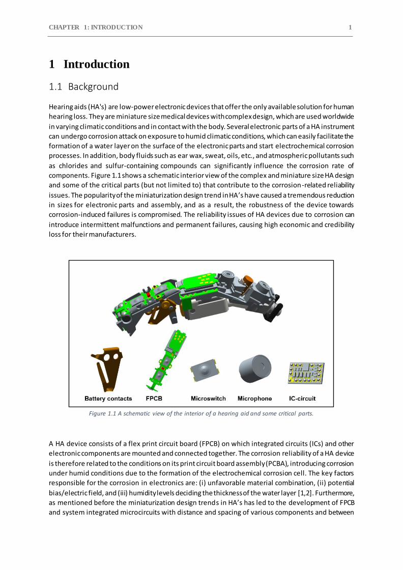
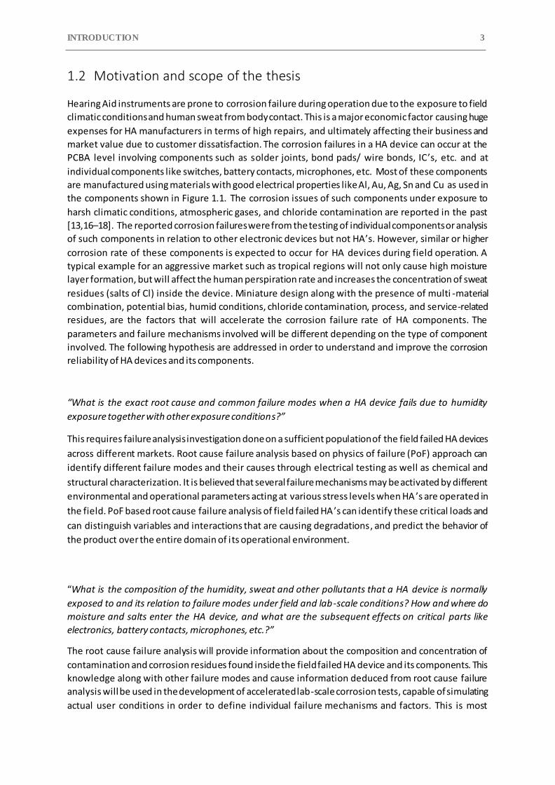
components. Figure 1.1 shows a schematic interior view of the complex and miniature size HA design
and some of the critical parts (but not limited to) that contribute to the corrosion-related reliability
issues. The popularity of the miniaturization design trend in HA’s have caused a tremendous reduction
in sizes for electronic parts and assembly, and as a result, the robustness of the device towards
corrosion-induced failures is compromised. The reliability issues of HA devices due to corrosion can
introduce intermittent malfunctions and permanent failures, causing high economic and credibility
loss for their manufacturers.
Figure 1.1 A schematic view of the interior of a hearing aid and some critical parts.
A HA device consists of a flex print circuit board (FPCB) on which integrated circuits (ICs) and other
electronic components are mounted and connected together. The corrosion reliability of a HA device
is therefore related to the conditions on its print circuit board assembly (PCBA), introducing corrosion
under humid conditions due to the formation of the electrochemical corrosion cell. The key factors
responsible for the corrosion in electronics are: (i) unfavorable material combination, (ii) potential
bias/electric field, and (iii) humidity levels deciding the thickness of the water layer [1,2]. Furthermore,
as mentioned before the miniaturization design trends in HA’s has led to the development of FPCB
and system integrated microcircuits with distance and spacing of various components and between
CHAPTER 1 2
components reduced down to μm (micrometer) scale. The reduced spacing can cause easy formation
of corrosion cell between biased points during local condensation under humid environments. The
synergetic effect of miniaturization, different metals/alloys, potential bias and humid conditions can
lead to formation of electrochemical cell locally on PCBA surface, which can cause a variety of
corrosion failure modes and moisture-related mechanisms such as surface insulation resistance (SIR)
reduction and subsequent electrochemical migration (ECM), galvanic corrosion, creep corrosion, and
cathodic anodic filament (CAF) [3–5].
The water layer formed on PCBA surface and electronic components have only limited conductivity to
cause any significant corrosion failure when the PCBA is biased. However, the PCBA surface is often
found contaminated with process-related residues from the chemicals or decomposed fraction of
compounds formed during the production process such as flux agents, etching medium, etc. [6]. The
other type of residue known as service-related residues are introduced when the device is exposed to
service environments and generally contain aggressive ions like chlorides, 𝑆𝑂2(𝑔), 𝑁𝑂𝑥 (𝑔), and dust
aerosol [7,8]. Both process and service-related ionic residues can dissolve into the water layer and
increase their conductivity to cause a reduction in SIR due to leak current. Moreover, the presence of
these ionic residues acts as moisture trapping agents due to their hygroscopic nature, which can lower
the critical relative humidity (cRH) levels for water layer build up inside the device through the process
of deliquescence. These residues can also retain moisture for a longer time even if the external
humidity drops due to low efflorescence humidity level (ERH). The generated leak current will cause
functionality or intermittent problems to the electronic device and will subsequently lead to the
permanent failure in the form of ECM. The time to ECM failure will depend on the thickness of water
layer, potential bias, and materials involved. Several solutions and strategies are available to improve
the corrosion reliability of electronics, like the cleanliness of PCBA surface, applying membranes to
protect the device from atmospheric or external contaminants, and protection by applying conformal
coating on electronics. Among all these protection methods, conformal coatings are widely accepted
as a corrosion protection method for electronic devices. Conformal coatings are polymeric coatings
that provide an effective barrier and can insulate the electronics parts and components from the
external corrosive environments. Their performance depends on the strength of the coating adhesion
to the substrate material. However, the majority of conformal coating failure occurs due to adhesion
loss upon exposure to harsh environmental conditions (high temperature and humidity) and due to
the presence of contamination on the substrate surface, which can lead to the electrolyte layer
formation at the coating-substrate interface, causing leak current and other corrosion phenomena’s
[9].
In order to improve the corrosion reliability of HA devices, it is essential to understand the effect of
various influencing factors and mechanisms involved in the failure of multiple components and device
as a whole. Although there are studies done in the past that address electronics reliability issues in
general under humid conditions and humidity build-up in an electronic enclosure, almost no literature
is available on failure mechanisms or investigation on HA reliability [6,10,11]. Few works are reported
on the failure analysis of hearing aid devices [12–15]. However, the information is limited to 1-2
devices that is not enough for a statistically relevant root cause analysis and for deducing common
failure mechanisms. The present study will focus on a Physics of Failure approach on a statistically
relevant group of failed devices from various parts of the world, which are exposed to a variety of
climatic conditions. The detailed knowledge from the field failure mechanisms together with
mechanistic understanding from the simulated laboratory experiments will lead to the possibilities for
the material use, process optimization, and innovative design of HA ’s with superior robustness
towards climatic and corrosion reliability.
INTRODUCTION 3
1.2 Motivation and scope of the thesis
Hearing Aid instruments are prone to corrosion failure during operation due to the exposure to field
climatic conditions and human sweat from body contact. This is a major economic factor causing huge
expenses for HA manufacturers in terms of high repairs, and ultimately affecting their business and
market value due to customer dissatisfaction. The corrosion failures in a HA device can occur at the
PCBA level involving components such as solder joints, bond pads/ wire bonds, IC’s, etc. and at
individual components like switches, battery contacts, microphones, etc. Most of these components
are manufactured using materials with good electrical properties like Al, Au, Ag, Sn and Cu as used in
the components shown in Figure 1.1. The corrosion issues of such components under exposure to
harsh climatic conditions, atmospheric gases, and chloride contamination are reported in the past
[13,16–18]. The reported corrosion failures were from the testing of individual components or analysis
of such components in relation to other electronic devices but not HA’s. However, similar or higher
corrosion rate of these components is expected to occur for HA devices during field operation. A
typical example for an aggressive market such as tropical regions will not only cause high moisture
layer formation, but will affect the human perspiration rate and increases the concentration of sweat
residues (salts of Cl) inside the device. Miniature design along with the presence of multi -material
combination, potential bias, humid conditions, chloride contamination, process, and service-related
residues, are the factors that will accelerate the corrosion failure rate of HA components. The
parameters and failure mechanisms involved will be different depending on the type of component
involved. The following hypothesis are addressed in order to understand and improve the corrosion
reliability of HA devices and its components.
“What is the exact root cause and common failure modes when a HA device fails due to humidity
exposure together with other exposure conditions?”
This requires failure analysis investigation done on a sufficient population of the field failed HA devices
across different markets. Root cause failure analysis based on physics of failure (PoF) approach can
identify different failure modes and their causes through electrical testing as well as chemical and
structural characterization. It is believed that several failure mechanisms may be activated by different
environmental and operational parameters acting at various stress levels when HA ’s are operated in
the field. PoF based root cause failure analysis of field failed HA ’s can identify these critical loads and
can distinguish variables and interactions that are causing degradations, and predict the behavior of
the product over the entire domain of its operational environment.
“What is the composition of the humidity, sweat and other pollutants that a HA device is normally
exposed to and its relation to failure modes under field and lab-scale conditions? How and where do
moisture and salts enter the HA device, and what are the subsequent effects on critical parts like
electronics, battery contacts, microphones, etc.?”
The root cause failure analysis will provide information about the composition and concentration of
contamination and corrosion residues found inside the field failed HA device and its components. This
knowledge along with other failure modes and cause information deduced from root cause failure
analysis will be used in the development of accelerated lab-scale corrosion tests, capable of simulating
actual user conditions in order to define individual failure mechanisms and factors. This is most
CHAPTER 1 4
important for a knowledge-based design strategy to design HA’s that can withstand the environmental
conditions and provide guidelines for developing lab-scale corrosion test methods for testing HA’s to
simulate real exposure conditions, better than the test conditions used today.
“Finally, some additional questions about whether the current corrosion protection method for HA
device and its component is good enough and what can be the best possible protection methods based
on the new knowledge ?”
Most HA’s electronic parts, and other components are protected using thin polymer-based conformal
coatings. The degree of corrosion on various components in the field will depend on the performance
of these coatings. The root cause failure analysis of field failed HA ’s will reveal the state of conformal
coatings and its ability to maintain good adhesion and structural integrity during field exposure. The
knowledge from this will be used to test the existing conformal coatings and other possible choice of
conformal coating types under accelerated field exposure conditions like high temperature, high
humidity, and the presence of field generated hygroscopic contaminants. Finally, a new conformal
coating type that suits the HA application and that can withstand its exposure conditions will be
deployed as a corrosion protection solution.
The work presented in the thesis addresses all the above hypothesis questions with results from
various investigations and analysis carried out on HA devices and its related components. These
investigations and analysis aim to provide hearing aid manufacturers with knowledge and guidelines
that can be implemented at the development stage and improve the climatic robustness of HA ’s. The
climatic reliability improvement of the HA device will depend on the careful choice of materials, design
considering critical surface parameters and geometrical factors, consideration of exposure conditions,
and finding compatible conformal coating types for corrosion protection, which overall can provide
high reliability, durability and quality products.
1.3 Structure of the thesis
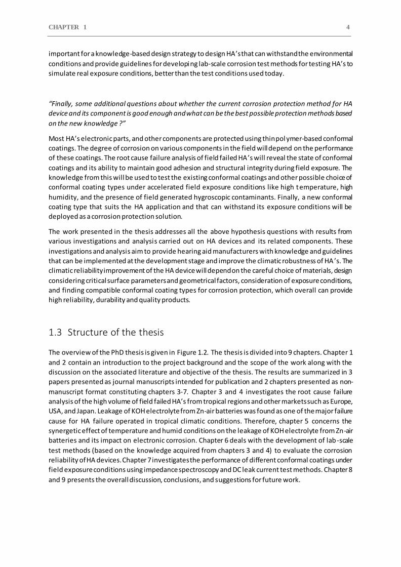
The overview of the PhD thesis is given in Figure 1.2. The thesis is divided into 9 chapters. Chapter 1
and 2 contain an introduction to the project background and the scope of the work along with the
discussion on the associated literature and objective of the thesis. The results are summarized in 3
papers presented as journal manuscripts intended for publication and 2 chapters presented as non-
manuscript format constituting chapters 3-7. Chapter 3 and 4 investigates the root cause failure
analysis of the high volume of field failed HA’s from tropical regions and other markets such as Europe,
USA, and Japan. Leakage of KOH electrolyte from Zn-air batteries was found as one of the major failure
cause for HA failure operated in tropical climatic conditions. Therefore, chapter 5 concerns the
synergetic effect of temperature and humid conditions on the leakage of KOH electrolyte from Zn-air
batteries and its impact on electronic corrosion. Chapter 6 deals with the development of lab-scale
test methods (based on the knowledge acquired from chapters 3 and 4) to evaluate the corrosion
reliability of HA devices. Chapter 7 investigates the performance of different conformal coatings under
field exposure conditions using impedance spectroscopy and DC leak current test methods. Chapter 8
and 9 presents the overall discussion, conclusions, and suggestions for future work.
INTRODUCTION 5
Figure 1.2 An overview of the PhD thesis structure.
CHAPTER 1 6
References
[1] M. Tencer, J.S. Moss, Humidity management of outdoor electronic equipment: Methods, pitfalls, and recommendations, IEEE Trans. Components Packag. Technol. 25 (2002) 66–72. https://doi.org/10.1109/6144.991177.
[2] R. Ambat, S.G. Jensen, P. Moller, Corrosion Reliability of Electronic Systems, in: ECS Trans., 2008: pp. 17–28. https://doi.org/10.1149/1.2900650.
[3] E.H. Wong, S.W. Koh, K.H. Lee, R. Rajoo, Comprehensive treatment of moisture induced failure - Recent advances, IEEE Trans. Electron. Packag. Manuf. 25 (2002) 223–230. https://doi.org/10.1109/TEPM.2002.804613.
[4] H. Conseil, M.S. Jellesen, V. Verdingovas, R. Ambat, Decomposition studies of no-clean solder flux systems in connection with corrosion reliability of electronics, Eurocorr 2013. (2013).
[5] D. Minzari, M.S. Jellesen, P. Møller, R. Ambat, On the electrochemical migration mechanism of tin in electronics, Corros. Sci. (2011). https://doi.org/10.1016/j.corsci.2011.06.015.
[6] K. Piotrowska, V. Verdingovas, M.S. Jellesen, R. Ambat, Contamination, potential bias and humidity effects on electrical performance and corrosion reliability of electronic devices, in: Eur. Corros. Congr. EUROCORR 2015, 2015.
[7] X.Y. Lin, J.G. Zhang, Dust corrosion, in: Proc. 50th IEEE Holm Conf. Electr. Contacts 22nd Int. Conf. Electr. Contacts, 2004. https://doi.org/10.1109/holm.2004.1353127.
[8] R.B. Comizzoli, R.P. Frankenthal, P.C. Milner, J.D. Sinclair, Corrosion of electronic materials and devices, Science (80-. ). (1986). https://doi.org/10.1126/science.234.4774.340.
[9] A.S. Khanna, High-Performance Organic Coatings, 2008. https://doi.org/10.1533/9781845694739.
[10] R. Ambat, M.S.M. Jellesen, D. MiNZARI, U. Rathinavelu, M.A.K. Johnsen, P. Westermann, P. Møller, Solder flux residues and electrochemical migration failures of electronic devices, Proc. Eurocorr. (2009).
[11] G.W. Warren, P. Wynblatt, M. Zamanzadeh, The role of electrochemical migration and moisture adsorption on the reliability of metallized ceramic substrates, J. Electron. Mater. 18 (1989). https://doi.org/10.1007/BF02657426.
[12] A. Islam, H.N. Hansen, F. Risager, P.T. Tang, Experimental investigation on corrosion properties of LDS MID for hearing aid applications, in: Annu. Tech. Conf. - ANTEC, Conf. Proc., 2014.
[13] V.C. Gudla, R. Ambat, Corrosion failure analysis of hearing aid battery-spring contacts, Eng. Fail. Anal. 79 (2017) 980–987. https://doi.org/10.1016/j.engfailanal.2017.05.045.
[14] S. Mathew, M. Alam, M. Pecht, Identification of failure mechanisms to enhance prognostic outcomes, J. Fail. Anal. Prev. (2012). https://doi.org/10.1007/s11668-011-9508-2.
[15] L.L. Tessa, B.P. Sood, M.G. Pecht, Field reliability estimation for cochlear implants, IEEE Trans. Biomed. Eng. 62 (2015). https://doi.org/10.1109/TBME.2015.2412127.
[16] E. Salahinejad, R. Eslami Farsani, L. Tayebi, Synergistic galvanic-pitting corrosion of copper electrical pads treated with electroless nickel-phosphorus/immersion gold surface finish, Eng. Fail. Anal. (2017). https://doi.org/10.1016/j.engfailanal.2017.03.001.
[17] M. Fayeka, A.S.M.A. Haseeb, M.A. Fazal, Electrochemical corrosion behaviour of Pb-free SAC

INTRODUCTION 7
105 and SAC 305 solder alloys: A comparative study, Sains Malaysiana. 46 (2017). https://doi.org/10.17576/jsm-2017-4602-14.
[18] D. Minzari, M.S. Jellesen, P. Møller, R. Ambat, Morphological study of silver corrosion in highly aggressive sulfur environments, Eng. Fail. Anal. 18 (2011). https://doi.org/10.1016/j.engfailanal.2011.07.003.
CHAPTER 2: LITERATURE REVIEW 8
2 Factors influencing climatic reliability of electronics
The climatic reliability of electronics is highly affected by its environmental field conditions. High
temperature and humidity conditions can cause water condensation on the electronic surfaces of
sufficient thickness to start electrochemical processes [1–3]. Electrochemical corrosion can occur due
to the presence of metals/alloys, potential bias, and humid conditions. The presence of both process
and service-related ionic residues on the PCBA surfaces can increase the conductivity of the water
layer and cause high corrosion rates [4–7]. Furthermore, the hygroscopic nature of these residues will
allow thicker water layer formation at lower relative humidity (RH) and can retain water for a long
time depending on the water releasing humidity level. All these factors will lead to high leakage
current and subsequent ECM failures [8,9]. Another important parameter to consider is the
temperature profile of the electronic components inside the device in relation to dew point , which is
dependent on field climatic conditions. The temperature variation on the electronics inside a tight
enclosure would cause variations in local RH conditions for the electronic surfaces; thereby, dew
formation is likely to form in a short time interval of temperature variation[10]. Therefore, the
presence of ionic residues and the accumulation of humidity inside the device enclosures become
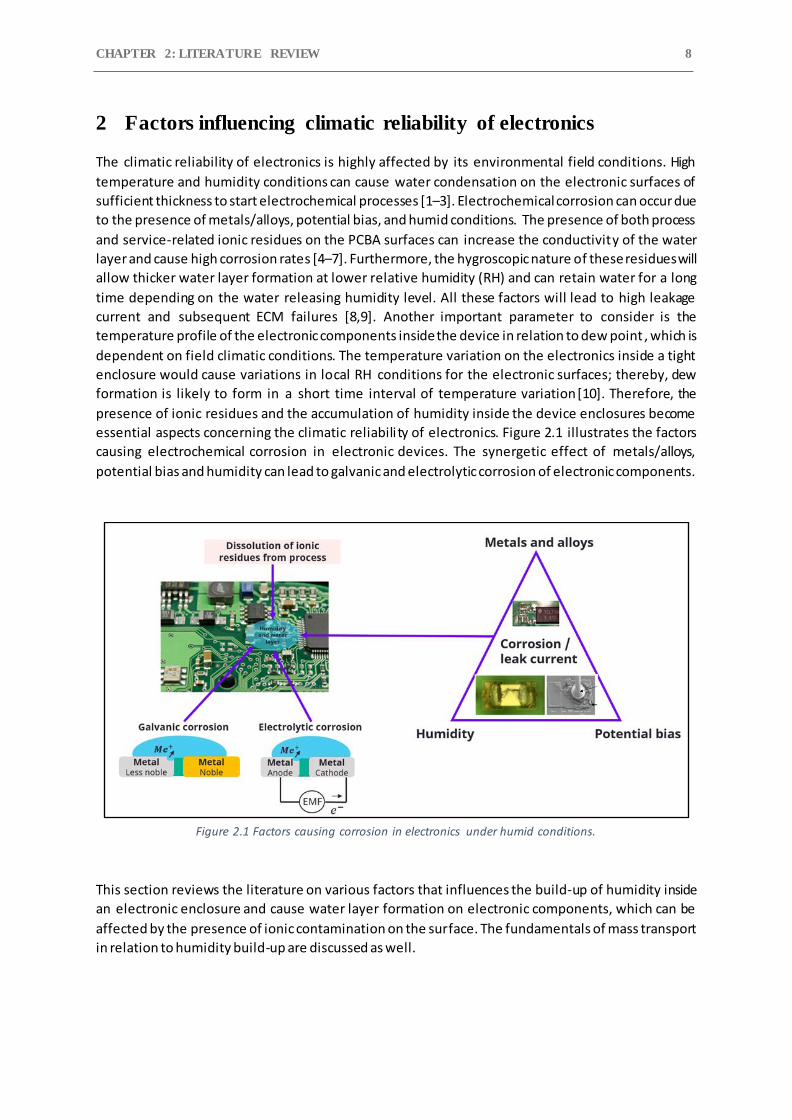
essential aspects concerning the climatic reliabili ty of electronics. Figure 2.1 illustrates the factors
causing electrochemical corrosion in electronic devices. The synergetic effect of metals/alloys,
potential bias and humidity can lead to galvanic and electrolytic corrosion of electronic components.
Figure 2.1 Factors causing corrosion in electronics under humid conditions.
This section reviews the literature on various factors that influences the build-up of humidity inside
an electronic enclosure and cause water layer formation on electronic components, which can be
affected by the presence of ionic contamination on the surface. The fundamentals of mass transport
in relation to humidity build-up are discussed as well.
LITERATURE REVIEW 9
2.1 Humidity
The interaction of electronics with humidity in the environment results in the formation of moisture
layer on their surface. Humidity is defined as the concentration of water vapor present in the air and
depends on the temperature and pressure of the system involved. For example, the same amount of
water vapor can cause high relative humidity in cool air than in warm air. The behavior of the water
vapor in the form of gas molecules can be derived from the ideal gas law shown in Eq. 2.1
𝑝. 𝑉 = 𝑛. 𝑅. 𝑇 (Eq. 2.1)
Where 𝑝 the absolute pressure (Pa), 𝑉 is the gas volume (𝑚3), 𝑛 is the amount of gas (kg), R is the gas
constant (8.3145(𝑚𝑜𝑙. 𝑘)−1). A closed container filled with water will experience vapor pressure
exerted by the moist air, which is a mixture of air molecules and water vapor molecules. The total
vapor pressure (𝑝𝑇) in that container will be the sum of partial pressure of the dry air (𝑝𝑎𝑖𝑟) and the
pressure of water vapor (𝑝𝑤) according to Eq. 2.2
𝑝𝑇 = 𝑝𝑎𝑖𝑟 + 𝑝𝑤 (Eq. 2.2)
The humidity is widely measured as relative and absolute humidity, which describes the content of
water vapor in the air, while dew point describes the conditions for condensation (moisture layer
formation).
2.1.1 Absolute humidity (AH)
It is the actual water vapor content of the air and is expressed as the mass of water vapor (𝑚𝐻2𝑂),
divided by the volume of the air and water vapor mixture (𝑉𝑛𝑒𝑡) as shown in Eq. 2.3. The absolute
humidity is not affected by the temperature, and at a particular specific temperature, air can be
saturated with water content.
𝐴𝐻 =𝑚𝐻2𝑂
𝑉𝑛𝑒𝑡 (
𝑔
𝑚3) (Eq. 2.3)
2.1.2 Relative humidity (RH)
It is expressed in percentage and is the ratio of the water vapor in the air and how much water vapor
can potentially be present at a given temperature. It is affected by the temperature and in situation
for example cold air, due to their incapacity to hold enough water vapor causes the water vapor to
condense. Therefore, RH can change in an enclosed electronic device by simply altering temperature
without any actual change to the moisture content of the air. As a result, the RH parameter has a more
pronounced effect on the corrosion of electronics than the AH parameter. It is expressed as the ratio
CHAPTER 2 10
of partial pressure of water vapor (𝑃𝑤) and the equilibrium vapor pressure of the water (𝑃0) at a given
temperature as shown in Eq. 2.4.
𝑅𝐻 = 𝑃𝑤
𝑃0 (%) (Eq. 2.4)
2.1.3 Dew Point (DP) Dew point temperature is defined as the temperature to which the air must be cooled to reach
saturation. Saturation occurs when air is holding maximum amount of water vapor at any given
temperature and pressure, which usually occurs when the dew point temperature is equal to the air
temperature. Dew point temperature can never be greater than air temperature and therefore, when
the air temperature decreases, the moisture is removed from the air by the process of condensation
in the form of tiny water droplets. Calculating dew point is complex but a very simple and quick
approximation equation shown in Eq. 2.5 allows conversion between dew point, temperature and
relative humidity, provided the relative humidity is more than 50% [11]. The accuracy of this approach
is about ±1 ˚C. The other widely used method to find the dew point is by using psychometric charts
[12].
𝑇𝑑𝑝 = 𝑇 − (100−𝑅𝐻
5) (Eq. 2.5)
2.2 Water layer formation on PCBA surface
The water molecules in the humid environment can interact with the electronics surface due to either
their good penetration ability (small size ~29Å3) or their capability to form hydrogen bond networks
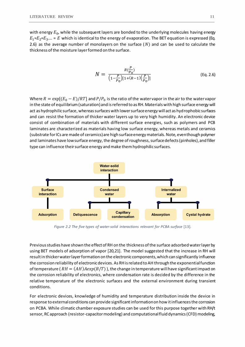
with surface molecules [13]. There are five major mechanisms of water-solid interaction, as shown in
Figure 2.2, which can be considered as the interaction between water and PCBA surface, interaction
with contaminants present on the PCBA surface, and interaction between the water and bulk material.
These mechanisms are adsorption on the PCBA surface, capillary condensation into porous structure,
deliquescence of hygroscopic contamination, formation of crystal hydrate and vapor absorption into
the bulk amorphous materials.
There are several models available describing the physiochemical adsorption of water on the PCBA
surface and moisture ingress into the electronic enclosures based on the Brunauer-Emmett-Teller
(BET) equation[14–16]. BET-based models have been the most widely used method for predicting the
moisture ingress through enclosures and adsorption by electronic components [17,18].
Brunauer-Emmett-Teller equation is the extension of Langmuir’s monolayer physical adsorption
theory, which was limited in explaining the multilayer adsorption process [19]. Since it assumes that
the adsorption is monolayer, which is only possible under low-pressure conditions, the Langmuir
equation is applicable only for low-pressure conditions.
On the other hand BET equation expresses the physical adsorption process as the formation of a
multilayer of liquid water [14]. In the BET model, the first layer of molecules are bonded to the surface
LITERATURE REVIEW 11
with energy 𝐸0, while the subsequent layers are bonded to the underlying molecules having energy
𝐸1=𝐸2=𝐸3…. = 𝐸 which is identical to the energy of evaporation. The BET equation is expressed (Eq.
2.6) as the average number of monolayers on the surface (𝑁) and can be used to calculate the
thickness of the moisture layer formed on the surface.
𝑁 = 𝑅(
𝑃
𝑃0)
(1−𝑃
𝑃0)[1+(𝑅−1)(
𝑃
𝑃0)]
(Eq. 2.6)
Where 𝑅 = exp[(𝐸0 − 𝐸)/𝑅𝑇] and 𝑃/𝑃0 is the ratio of the water vapor in the air to the water vapor
in the state of equilibrium (saturation) and is referred to as RH. Materials with high surface energy will
act as hydrophilic surface, whereas surfaces with lower surface energy will act as hydrophobic surfaces
and can resist the formation of thicker water layers up to very high humidity. An electronic device
consist of combination of materials with different surface energies, such as polymers and PCB
laminates are characterized as materials having low surface energy, whereas metals and ceramics
(substrate for ICs are made of ceramics) are high surface energy materials. Note, even though polymer
and laminates have low surface energy, the degree of roughness, surface defects (pinholes), and filler
type can influence their surface energy and make them hydrophilic surfaces.
Figure 2.2 The five types of water-solid interactions relevant for PCBA surface [13].
Previous studies have shown the effect of RH on the thickness of the surface adsorbed water layer by
using BET models of adsorption of vapor [20,21]. The model suggested that the increase in RH will
result in thicker water layer formation on the electronic components, which can significantly influence
the corrosion reliability of electronic devices. As RH is related to AH through the exponential function
of temperature ( 𝑅𝐻 = (𝐴𝐻)𝐴𝑒𝑥𝑝(𝐵/𝑇) ), the change in temperature will have significant impact on
the corrosion reliability of electronics, where condensation rate is decided by the difference in the
relative temperature of the electronic surfaces and the external environment during transient
conditions.
For electronic devices, knowledge of humidity and temperature distribution inside the device in
response to external conditions can provide significant information on how it influences the corrosion
on PCBA. While climatic chamber exposure studies can be used for this purpose together with RH/t
sensor, RC approach (resistor-capacitor modeling) and computational fluid dynamics (CFD) modeling,
CHAPTER 2 12
which are complementary methods used for predicting the moisture ingress into electronic enclosures
through modeling using complex climatic profiles that can provide detailed information on
temperature and humidity distribution [16,17,22].
2.2.1 Effect of surface morphology of electronic components
The formation of the water layer on electronic components not only depends on the climatic
conditions but equally depends on the surface morphology and the surface energy (originating from
chemical composition) of the component surfaces. For example, a print circuit board (PCB) consists of
FR-4 laminate coated with a soldermask. Soldermask is polymeric coating with fillers that are used to
protect and insulate circuitry (metal layers) from interacting with solder material during SMT (surface
mount technology) process. Whereas laminate is made of epoxy resin reinforced with glass fibers [23]
and constitutes metal tracks. The fillers, polymers, and additives are considered hydrophilic materials
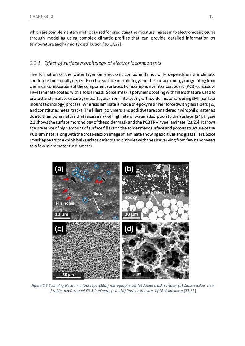
due to their polar nature that raises a risk of high rate of water adsorption to the surface [24]. Figure
2.3 shows the surface morphology of the solder mask and the PCB FR-4 type laminate [23,25]. It shows
the presence of high amount of surface fillers on the solder mask surface and porous structure of the
PCB laminate, along with the cross-section image of laminate showing additives and glass fillers. Solde
rmask appears to exhibit bulk surface defects and pinholes with the size varying from few nanometers
to a few micrometers in diameter.
Figure 2.3 Scanning electron microscope (SEM) micrographs of: (a) Solder mask surface, (b) Cross-section view
of solder mask coated FR-4 laminate, (c and d) Porous structure of FR-4 laminate [23,25].
LITERATURE REVIEW 13
The hydrophilic behavior of the fillers and additives found in soldermask and laminates can be related
to the high surface wettability of these materials. Surface wettability is the measurement of liquid
ability of interaction with solid surfaces and measures the level of wetting [26]. The surface wettability
of any surface can be determined by measuring the water contact angle formed by the intersection of
the liquid-solid interface between the surface level and the tangent line drawn from the contact point
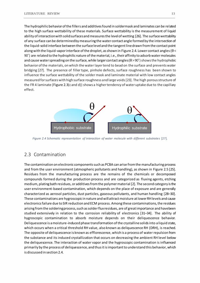
along with the liquid-vapor interface of the droplet, as shown in Figure 2.4. Lower contact angles (θ <
90˚) are related to the hydrophilic nature of the material, i.e., their affinity to adsorb water molecules
and cause water spreading on the surface, while larger contact angles (θ > 90˚) shows the hydrophobic
behavior of the materials, on which the water layer tend to bead on the surface and prevents water
bridging [27]. The presence of filler type, pinhole defects, surface roughness has been shown to
influence the surface wettability of the solder mask and laminate material with low contact angles
measured for surfaces with high surface roughness and large voids [23]. The high porous structure of
the FR 4 laminate (Figure 2.3(c and d)) shows a higher tendency of water uptake due to the capillary
effect.
Figure 2.4 Schematic representation of interaction of water molecule with different substrates [27].
2.3 Contamination
The contamination on electronic components such as PCBA can arise from the manufacturing process
and from the user environment (atmospheric pollutants and handling), as shown in Figure 2.5 [25].
Residues from the manufacturing process are the remains of the chemicals or decomposed
compounds formed during the production process and are categorized as fluxing agents, etching
medium, plating bath residues, or additives from the polymer material [2]. The second category is the
user environment-based contamination, which depends on the place of exposure and are generally
characterized as aerosol particles, dust particles, gaseous pollutants, and human handling [28–30].
These contaminations are hygroscopic in nature and will attract moisture at lower RH levels and cause
electronics failure due to SIR reduction and ECM process. Among these contaminations, the residues
arising from the soldering process, such as solder flux residues, are of great importance and have been
studied extensively in relation to the corrosion reliability of electronics [31–34]. The ability of
hygroscopic contamination to absorb moisture depends on their deliquescence behavior.
Deliquescence is a moisture-induced phase transformation of the crystalline solids into a liquid state,
which occurs when a critical threshold RH value, also known as deliquescence RH (DRH), is reached.
The opposite of deliquescence is known as efflorescence, which is a process of water repulsion from
the substance and its induced crystallization that occurs on decreasing the ambient RH level below
the deliquescence. The interaction of water vapor and the hygroscopic contamination is influenced
primarily by the process of deliquescence, and thus it is important to understand this behavior, which
is discussed in section 2.4.
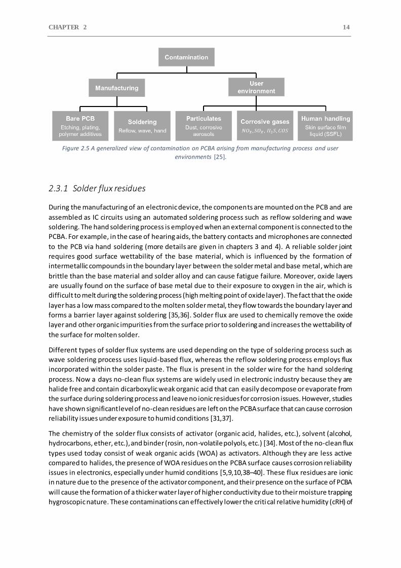
CHAPTER 2 14
Figure 2.5 A generalized view of contamination on PCBA arising from manufacturing process and user
environments [25].
2.3.1 Solder flux residues
During the manufacturing of an electronic device, the components are mounted on the PCB and are
assembled as IC circuits using an automated soldering process such as reflow soldering and wave
soldering. The hand soldering process is employed when an external component is connected to the
PCBA. For example, in the case of hearing aids, the battery contacts and microphones are connected
to the PCB via hand soldering (more details are given in chapters 3 and 4). A reliable solder joint
requires good surface wettability of the base material, which is influenced by the formation of
intermetallic compounds in the boundary layer between the solder metal and base metal, which are
brittle than the base material and solder alloy and can cause fatigue failure. Moreover, oxide layers
are usually found on the surface of base metal due to their exposure to oxygen in the air, which is
difficult to melt during the soldering process (high melting point of oxide layer). The fact that the oxide
layer has a low mass compared to the molten solder metal, they flow towards the boundary layer and
forms a barrier layer against soldering [35,36]. Solder flux are used to chemically remove the oxide
layer and other organic impurities from the surface prior to soldering and increases the wettability of
the surface for molten solder.
Different types of solder flux systems are used depending on the type of soldering process such as
wave soldering process uses liquid-based flux, whereas the reflow soldering process employs flux
incorporated within the solder paste. The flux is present in the solder wire for the hand soldering
process. Now a days no-clean flux systems are widely used in electronic industry because they are
halide free and contain dicarboxylic weak organic acid that can easily decompose or evaporate from
the surface during soldering process and leave no ionic residues for corrosion issues. However, studies
have shown significant level of no-clean residues are left on the PCBA surface that can cause corrosion
reliability issues under exposure to humid conditions [31,37].
The chemistry of the solder flux consists of activator (organic acid, halides, etc.), solvent (alcohol,
hydrocarbons, ether, etc.), and binder (rosin, non-volatile polyols, etc.) [34]. Most of the no-clean flux
types used today consist of weak organic acids (WOA) as activators. Although they are less active
compared to halides, the presence of WOA residues on the PCBA surface causes corrosion reliability
issues in electronics, especially under humid conditions [5,9,10,38–40]. These flux residues are ionic
in nature due to the presence of the activator component, and their presence on the surface of PCBA
will cause the formation of a thicker water layer of higher conductivity due to their moisture trapping
hygroscopic nature. These contaminations can effectively lower the criti cal relative humidity (cRH) of
LITERATURE REVIEW 15
the electronics and will increase their chances of ECM failure by increasing their susceptibility for
moisture condensation and providing good electrolytes for corrosion occurrence [41,42].
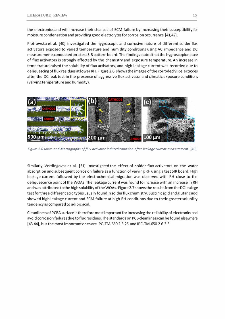
Piotrowska et al. [40] investigated the hygroscopic and corrosive nature of different solder flux
activators exposed to varied temperature and humidity conditions using AC impedance and DC
measurements conducted on a test SIR pattern board. The findings stated that the hygroscopic nature
of flux activators is strongly affected by the chemistry and exposure temperature. An increase in
temperature raised the solubility of flux activators, and high leakage current was recorded due to
deliquescing of flux residues at lower RH. Figure 2.6 shows the images of the corroded SIR electrodes
after the DC leak test in the presence of aggressive flux activator and climatic exposure conditions
(varying temperature and humidity).
Figure 2.6 Micro and Macrographs of flux activator induced corrosion after leakage current measurement [40].
Similarly, Verdingovas et al. [31] investigated the effect of solder flux activators on the water
absorption and subsequent corrosion failure as a function of varying RH using a test SIR board. High
leakage current followed by the electrochemical migration was observed with RH close to the
deliquescence point of the WOAs. The leakage current was found to increase with an increase in RH
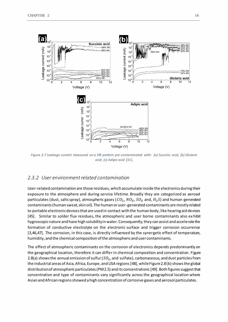
and was attributed to the high solubility of the WOAs. Figure 2.7 shows the results from the DC leakage
test for three different acid types usually found in solder flux chemistry. Succinic acid and glutaric acid
showed high leakage current and ECM failure at high RH conditions due to their greater solubility
tendency as compared to adipic acid.
Cleanliness of PCBA surface is therefore most important for increasing the reliability of electronics and
avoid corrosion failures due to flux residues. The standards on PCB cleanliness can be found elsewhere
[43,44], but the most important ones are IPC-TM-650 2.3.25 and IPC-TM-650 2.6.3.3.
CHAPTER 2 16
Figure 2.7 Leakage current measured on a SIR pattern pre-contaminated with: (a) Succinic acid, (b) Glutaric
acid, (c) Adipic acid [31].
2.3.2 User environment related contamination
User-related contamination are those residues, which accumulate inside the electronics during their
exposure to the atmosphere and during service lifetime. Broadly they are categorized as aerosol
particulates (dust, salts spray), atmospheric gases (𝐶𝑂2, 𝑁𝑂𝑋, 𝑆𝑂𝑋 and, 𝐻2𝑆) and human-generated
contaminants (human sweat, skin oil). The human or user-generated contaminants are mostly related
to portable electronic devices that are used in contact with the human body, like hearing aid devices
[45]. Similar to solder flux residues, the atmospheric and user borne contaminants also ex hibit
hygroscopic nature and have high solubility in water. Consequently, they can assist and accelerate the
formation of conductive electrolyte on the electronic surface and trigger corrosion occurrence
[3,46,47]. The corrosion, in this case, is directly influenced by the synergetic effect of temperature,
humidity, and the chemical composition of the atmospheric and user contaminants.
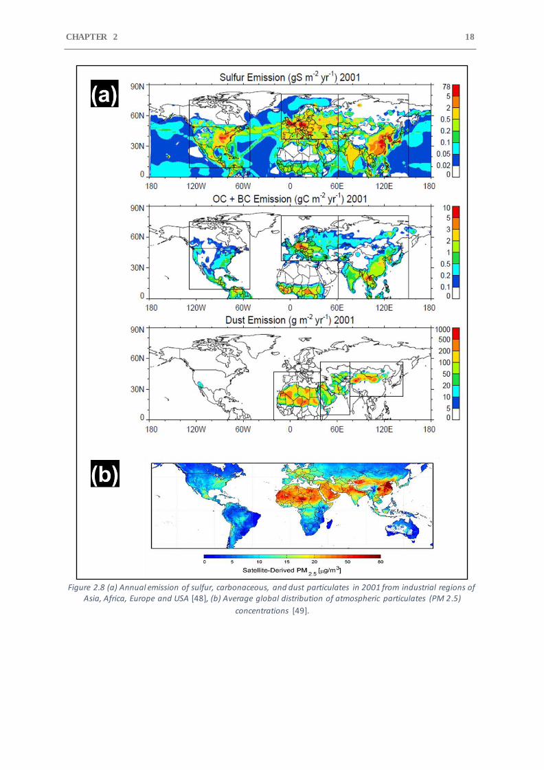
The effect of atmospheric contaminants on the corrosion of electronics depends predominantly on
the geographical location, therefore it can differ in chemical composition and concentration. Figure
2.8(a) shows the annual emission of sulfur (𝑆𝑂2, and sulfate), carbonaceous, and dust particles from
the industrial areas of Asia, Africa, Europe, and USA regions [48], while Figure 2.8 (b) shows the global
distribution of atmospheric particulates (PM 2.5) and its concentrations [49]. Both figures suggest that
concentration and type of contaminants vary significantly across the geographical location where
Asian and African regions showed a high concentration of corrosive gases and aerosol particulates.

LITERATURE REVIEW 17
Atmospheric aerosol particles (dust) are chemical species suspended in the atmosphere an d are
composed of chlorides, sulfates, nitrates, carbonates, and ammoniums. Their characteristics changes
rapidly in time and space depending on different prevailing circumstances in the atmosphere, such as
chemical mixing, particulate coagulation, and chemical reaction. Therefore, they are known to contain
sea salt and metal particles. Electronic devices can accumulate these atmospheric aerosols during
their field operation, which will lower the deliquescence RH of the device due to their hygroscopic
nature and accelerate electronic failures. The deliquescence relative humidity (DRH) of some common
aerosols are given in section 2.4, Table 2.1. Previous studies have shown the impact of aerosol particles
on the corrosion of Au/Ni plated electrical connectors used in Asian countries [45,50,51]. The
electrolyte consisting of aerosol particles containing 𝐶𝑙−and 𝑆𝑂4− ions caused galvanic corrosion of
the connectors through the pores and defects in the gold plating.
CHAPTER 2 18
Figure 2.8 (a) Annual emission of sulfur, carbonaceous, and dust particulates in 2001 from industrial regions of
Asia, Africa, Europe and USA [48], (b) Average global distribution of atmospheric particulates (PM 2.5)
concentrations [49].
LITERATURE REVIEW 19
Along with atmospheric pollutants, various atmospheric gases (𝐶𝑂2, 𝑁𝑂𝑋, 𝑆𝑂𝑋 and, 𝐻2𝑆) are known
to cause corrosion of electronic components such as PCBA under humid conditions [29]. Industrially
polluted areas usually contain a high concentration of elemental sulfur, sulfide, and/or sulfur dioxide
in the atmosphere [52]. Due to the high electrical and corrosion-resistant properties, Ag and Cu are
used extensively for electronics manufacturing, such as silver flakes as conductive filament, silver-
plated copper frame for microswitch, Sn-Ag-Cu solder alloy, internal copper layers in PCB, and many
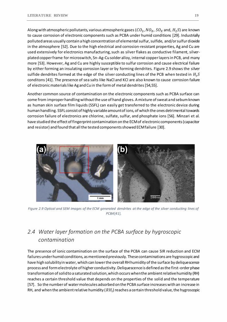
more [53]. However, Ag and Cu are highly susceptible to sulfur corrosion and cause electrical failure
by either forming an insulating corrosion layer or by forming dendrites. Figure 2.9 shows the silver
sulfide dendrites formed at the edge of the silver conducting lines of the PCB when tested in 𝐻𝑠𝑆
conditons [41]. The presence of sea salts like NaCl and KCl are also known to cause corrosion failure
of electronic materials like Ag and Cu in the form of metal dendrites [54,55].
Another common source of contamination on the electronic components such as PCBA surface can
come from improper handling without the use of hand gloves. A mixture of sweat and sebum known
as human skin surface film liquids (SSFL) can easily get transferred to the electronic device during
human handling. SSFL consist of highly variable amount of ions, of which the ones detrimental towards
corrosion failure of electronics are chlorine, sulfate, sulfur, and phosphate ions [56]. Minzari et al.
have studied the effect of fingerprint contamination on the ECM of electronic components (capacitor
and resistor) and found that all the tested components showed ECM failure [30].
Figure 2.9 Optical and SEM images of the ECM generated dendrites at the edge of the silver conducting lines of
PCBA[41].
2.4 Water layer formation on the PCBA surface by hygroscopic
contamination
The presence of ionic contamination on the surface of the PCBA can cause SIR reduction and ECM
failures under humid conditions, as mentioned previously. These contaminations are hygroscopic and
have high solubility in water, which can lower the overall RH humidity of the surface by deliquescence
process and form electrolyte of higher conductivity. Deliquescence is defined as the first-order phase
transformation of solid to a saturated solution, which occurs when the ambient relative humidity (RH)
reaches a certain threshold value that depends on the properties of the solid and the temperature
[57]. So the number of water molecules adsorbed on the PCBA surface increases with an increase in
RH, and when the ambient relative humidity (𝑅𝐻𝑖) reaches a certain threshold value, the hygroscopic
CHAPTER 2 20
contaminants will deliquesce and will form a conductive solution. This threshold relative humidity
value at which the deliquescence of contamination occurs is denoted as 𝑅𝐻𝑜 for discussion purpose,
and it is called Deliquescence Relative Humidity (DRH).
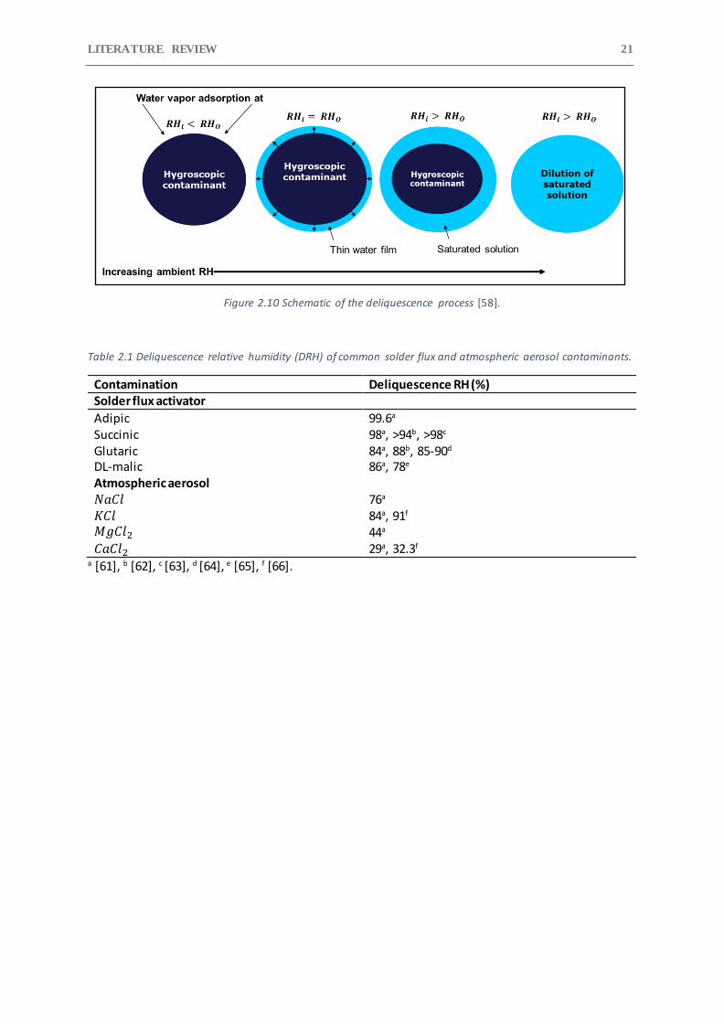
The deliquescence process of hygroscopic contaminants is shown in Figure 2.10 [58]. When the 𝑅𝐻𝑖
is below the 𝑅𝐻𝑜 than the contaminants will interact with water by adsorption process. It is expected
that thin monolayer of water molecules are adsorbed by the contamination during such case [59].
Upon increasing the 𝑅𝐻𝑖, more amount of water will be adsorbed by the contamination and at some
point the 𝑅𝐻𝑖 will exceed the 𝑅𝐻𝑜 of the contamination, which will lead to development of thin film
of saturated solution on the contaminated surface. The formed water layer has lower water vapor
pressure due to high water solubility and large colligative (binding of molecules together) of the
deliquescent contaminants compared to the pure water, and forms the basis for deliquescence
process [60]. The substantial decrease of the water vapor pressure of the saturated aqueous solution
(water-contamination solution) will cause condensation to occur at relatively lower RH [60]. This can
be understood by considering the chemical potential of pure liquid water (μ) in equilibrium with its
vapor, as expresses in Eq. 2.7.
𝜇 = 𝜇0 + 𝑅𝑇 ln 𝑝𝑂 (Eq. 2.7)
Where 𝑝𝑂 is the vapor pressure, 𝜇0 is the standard chemical potential, R is the gas constant and T is
the temperature. For a saturated solution having lower vapor pressure than 𝑝𝑂, and chemical
potential 𝜇𝑠, then the difference in the chemical potential between water in the solution and the pure
water is expressed in Eq. 2.8.
𝜇 − 𝜇0 = 𝑅𝑇 ln (𝑝𝑠
𝑝𝑂) (Eq. 2.8)
The water film in the formed saturated solution has lower thermodynamic activity relative to pure
water, and thus the condensation will occur when the vapor pressure exceeds 𝑝𝑠 , or equivalently
when the RH of the surroundings exceeds 𝑅𝐻𝑜. The water vapor condensing into the film will increase
the vapor pressure to the level of surrounding water vapor pressure, which will continue the
dissolution of contamination until it forms a saturated aqueous solution, bringing the vapor pressure
back down to 𝑅𝐻𝑜. The process of condensation and dissolution occur alternatively until all the
contamination is dissolved.
From a corrosion reliability point of view, the level of RH is critical, which will decide the deliquescence
of contaminants and initiation of corrosion failures like SIR reduction and ECM. The deliquescence
relative humidity of some common solder flux residues and atmospheric aerosol are given in Table
2.1. The table shows that atmospheric generated salt residues have lower RH for deliquescence
compared to the solder flux residues and can therefore have more impact on corrosion reliability of
electronics.
LITERATURE REVIEW 21
Figure 2.10 Schematic of the deliquescence process [58].
Table 2.1 Deliquescence relative humidity (DRH) of common solder flux and atmospheric aerosol contaminants.
Contamination Deliquescence RH (%) Solder flux activator
Adipic 99.6a
Succinic 98a, >94b, >98c
Glutaric 84a, 88b, 85-90d
DL-malic 86a, 78e Atmospheric aerosol 𝑁𝑎𝐶𝑙 76a
𝐾𝐶𝑙 84a, 91f 𝑀𝑔𝐶𝑙2 44a 𝐶𝑎𝐶𝑙2 29a, 32.3f
a [61], b [62], c [63], d [64], e [65], f [66].

CHAPTER 2 22
3 Humidity and contamination induced failure in electronics
It was previously argued that humidity, together with process and service contamination, can cause
number of failures on the electronic components such as PCBA by forming a thick conductive layer on
the metal parts of electronics. This section deals with the typical failure modes that can occur in
electronic devices when they are exposed to humidity and contamination during service life. Only
important failure modes relevant to the content of the present thesis are discussed.
3.1 Surface insulation reduction (SIR) or leak current failures
Surface insulation resistance is defined as the resistance between two conductors separated by some
dielectric material [67]. Current leakage will occur between the conductors, which will depend on the
resistivity of the dielectric material. When electronic devices are exposed to a humid environment,
the water is adsorbed on most surfaces. The amount of the adsorbed water is affected by the
temperature, humidity, contamination level, and the surface morphology of the surfaces, as discussed
earlier. Similarly, the plastics and polymer material will absorb the water under those conditions. The
adsorbed and absorbed water will affect the surface insulation resistance of the circuitry. An increase
in the amount and conductivity of the water layer under biased conditions will cause a significant
reduction in SIR and a subsequent increase in leakage current. The majority of field failures of
electronic devices under harsh environmental conditions occur due to SIR drop. However, SIR failure
doesn’t always lead to physical damage and therefore are difficult to trace during failure inspection.
SIR testing are widely used to evaluate the impact of contaminants and climatic condition on the level
of leakage current generated. Previous studies have used SIR testing to investigate the corrosive
behavior of different solder flux residues under varying humidity conditions and characterized them
based on the threshold RH, above which a sudden increase in leakage current and significant drop in
SIR was observed. This threshold RH was correlated to the deliquescence RH of the solder flux
contaminants [25,31]. An example of the effect of solder flux residues on the SIR and leakage current
under exposure to varying humidity and temperature conditions is shown previously in Figure 2.7.
The SIR reduction and leak current failures are problematic because of the presence of contamination
on the surface of the PCBA. The contamination generated from manufacturing can be removed by the
cleaning process, while the PCBA can be protected from service contamination by applying a
conformal coating. The performance of conformal coating will depend on the cleanliness of the PCBA
surface since solder flux residues and other organic contaminants, together with humidity, will cause
delamination of conformal coating. Rathinavelu at el. [37,68] used the SIR and leakage current testing
for performance evaluation of acrylate and silicon type conformal coatings , coated on flux
contaminated SIR pattern test board. The study reported high leakage current and ECM failures of SIR
electrodes under humid conditions for both acrylate and silicone conformal coatings.
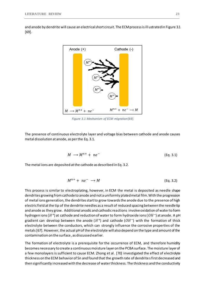
3.2 Electrochemical migration (ECM)
Electrochemical migration (ECM) is the process of migration of metal or metal-salt ions from the anode
towards the cathode connected by the electrolyte under the influence of potential bias. The migration
of metal ions from the anode to cathode results in the formation of a metal filament of needle shape
known as dendrites that grow from the cathode to anode [67] (Figure 3.2). The bridging of cathode
LITERATURE REVIEW 23
and anode by dendrite will cause an electrical short circuit. The ECM process is ill ustrated in Figure 3.1
[69].
Figure 3.1 Mechanism of ECM migration[69]
The presence of continuous electrolyte layer and voltage bias between cathode and anode causes
metal dissolution at anode, as per the Eq. 3.1.
𝑀 ⟶ 𝑀𝑛+ + 𝑛𝑒− (Eq. 3.1)
The metal ions are deposited at the cathode as described in Eq. 3.2.
𝑀𝑛+ + 𝑛𝑒− ⟶ 𝑀 (Eq. 3.2)
This process is similar to electroplating, however, in ECM the metal is deposited as needle shape
dendrites growing from cathode to anode and not a uniformly plated metal film. With the progression
of metal ions generation, the dendrites start to grow towards the anode due to the presence of high
electric field at the tip of the dendrite needles as a result of reduced spacing between the needle tip
and anode as they grow. Additional anodic and cathodic reactions involve oxidation of water to form
hydrogen ions (𝐻+) at cathode and reduction of water to form hydroxide ions (𝑂𝐻−) at anode. A pH
gradient can develop between the anode (𝐻+) and cathode (𝑂𝐻−) with the formation of thick
electrolyte between the conductors, which can strongly influence the corrosive properties of the
metals [67]. However, the actual pH of the electrolyte will also depend on the type and amount of the
contamination on the surface, as discussed earlier.
The formation of electrolyte is a prerequisite for the occurrence of ECM, and therefore humidity
becomes necessary to create a continuous moisture layer on the PCBA surface. The moisture layer of
a few monolayers is sufficient to cause ECM. Zhong et al. [70] investigated the effect of electrolyte
thickness on the ECM behavior of Sn and found that the growth rate of dendrite s first decreased and
then significantly increased with the decrease of water thickness. The thickness and the conductivity
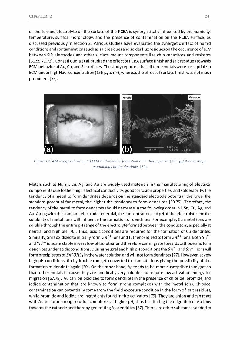
CHAPTER 2 24
of the formed electrolyte on the surface of the PCBA is synergistically influenced by the humidity,
temperature, surface morphology, and the presence of contamination on the PCBA surface, as
discussed previously in section 2. Various studies have evaluated the synergetic effect of humid
conditions and contaminations such as salt residues and solder flux residues on the occurrence of ECM
between SIR electrodes and other surface mount components like chip capacitors and resistors
[31,55,71,72]. Conseil Gudla et al. studied the effect of PCBA surface finish and salt residues towards
ECM behavior of Au, Cu, and Sn surfaces. The study reported that all three metals were susceptible to
ECM under high NaCl concentration (156 μg.cm-2), whereas the effect of surface finish was not much
prominent [55].
Figure 3.2 SEM images showing (a) ECM and dendrite formation on a chip capacitor[73], (b) Needle shape
morphology of the dendrites [74].
Metals such as Ni, Sn, Cu, Ag, and Au are widely used materials in the manufacturing of electrical
components due to their high electrical conductivity, good corrosion properties, and solderability. The
tendency of a metal to form dendrites depends on the standard electrode potential: the lower the
standard potential for metal, the higher the tendency to form dendrites [30,75]. Therefore, the
tendency of the metal to form dendrites should decrease in the following order: Ni, Sn, Cu, Ag, and
Au. Along with the standard electrode potential, the concentration and pH of the electrolyte and the
solubility of metal ions will influence the formation of dendrites. For example, Cu metal ions are
soluble through the entire pH range of the electrolyte formed between the conductors, especially at
neutral and high pH [76]. Thus, acidic conditions are required for the formation of Cu dendrites.
Similarly, Sn is oxidized to initially form 𝑆𝑛2+ ions and futher oxidized to form 𝑆𝑛4+ ions. Both 𝑆𝑛2+
and 𝑆𝑛4+ ions are stable in very low pH solution and therefore can migrate towards cathode and form
dendrites under acidic conditions. During neutral and high pH conditions the 𝑆𝑛2+ and 𝑆𝑛4+ ions will
form precipitates of 𝑆𝑛(𝑂𝐻)4 in the water solution and will not form dendrites [77]. However, at very
high pH conditions, tin hydroxide can get converted to stannate ions giving the possibility of the
formation of dendrite again [30]. On the other hand, Ag tends to be more susceptible to migration
than other metals because they are anodically very soluble and require low activation energy for
migration [67,78]. Au can be oxidized to form dendrites in the presence of chloride, bromide, and
iodide contamination that are known to form strong complexes with the metal ions. Chloride
contamination can potentially come from the field exposure condition in the form of salt residues,
while bromide and iodide are ingredients found in flux activators [79]. They are anion and can react
with Au to form strong solution complexes at higher pH, thus facilitating the migration of Au ions
towards the cathode and thereby generating Au dendrites [67]. There are other substances added to

LITERATURE REVIEW 25
the solder flux residues, which forms complexes with metals on the PCBA circuit like Sn, Cu, and Ag in
order to increase their soldering properties. But it is indeed important to note that the formation of
complex forming compounds are highly favorable for the formation of dendrites.
3.3 Conductive anodic filament formation
The conductive anodic filament (CAF) formation occurs within the laminate of the PCB, between the
embedded copper conducting traces and copper-plated via holes. The CAF formation is a voltage
induced electrochemical process in which metal salt grows from anode to cathode along the epoxy-
glass interface of the PCB laminate [67]. The failure due to CAF will require ingress of the moisture
into the PCB base material and the risk of failure will depend on the amount of moisture absorbed.
The various interfaces within the PCB laminate can degrade in the presence of residual stress within
laminate, humidity and temperature conditions, which can increase moisture ingress and debonding
of the interface [80]. The degraded epoxy-glass fiber will create a path for the copper containing
conductive filament to migrate.
The mechanism requires low pH condition for producing soluble Cu(I) ions at the anode. This is
achieved by the generation of H+ ions at anode during electrolysis of water, producing a pH gradient
between anode (acidic) and cathode (basic). The Cu(I) ions migrate along the glass fiber/epoxy
interface towards cathode, thus the copper forms an insoluble copper salt precipitate at the cathode
due to high pH. The CAF growth continues as long as the pH gradient is maintained and the gap
between conductors is sufficient to allow flow of leakage current. Figure 3.3(a) illustrates the
formation of CAF between Cu conducting traces inside PCB laminate, and Figure 3.3(b) shows the SEM
cross-section of a PCB and CAF visible around the glass fibers[81].
The CAF occurrence is influenced by a number of factors such as climatic conditions (temperature and
humidity), applied potential bias, contamination, the distance between the electrodes, and defects in
the PCB laminate like porosity as a result of high surface roughness that can easily absorb water by
capillary condensation effect [81–83].
Figure 3.3 (a) Formation of CAF, (b) Cross-section of a PCB showing CAF surrounding the epoxy-glass interface
using SEM/BSED [81].
CHAPTER 2 26
3.4 Galvanic corrosion
Various metals are used in electronics due to their good electrical and solderability, such as Cu, Al, Au,
Ag, Ni, and Sn. These materials belong to the group of active-passive material because of their ability
to form passive layers that protect them from corrosion to some level. The exposure of electronic
devices to humid conditions along with the presence of contamination on the PCBA surface can cause
high conductive electrolyte to form on the surface and bridge different metals. When two metals with
different standard electrode potential are connected by an electrolyte will lead to an electrochemical
corrosion process known as galvanic corrosion. The metal/alloy with higher electrode potential act as
a cathode, while the metal with lower electrode potential acts as anode and undergoes corrosion
attack. The kinetics of galvanic corrosion depends mostly on the difference in the standard electrode
potential between metals involved, the area ratio of cathode vs anode, and the concentration of the
electrolyte. The miniaturization of electronic devices, especially in low-power electronic devices like
cell phones, earphones and hearing aids, will experience an accelerated rate of galvanic corrosion. The
size and space between the components of PCBA are reduced to micrometer level, which can easily
cause the formation of the galvanic corrosion cell due to water condensation and external pollutants.
The galvanic corrosion failures in electronics have been mostly related to the components which are
connected or manufactured using different material combination. Examples are gold-plated copper
pads and metallization lines (conducting traces ) on the PCB surface, ball bonding which consists of a
combination of different metals (Au/Al, Au/Ag, etc.), and gold-plated connectors and microswitch [84–
86]. Various studies have reported the galvanic corrosion attack of ENIG (electrol ess Nickel-gold)
plated copper pads, conducting traces and connectors in the presence of chloride and sulfur-
containing environments [84,86–89].
The sequential mechanism involved in the galvanic corrosion of the above ENIG plated electronic
components is explained by considering an ENIG plated Cu substrate exposed to chloride
contamination and humid conditions. The ENIG consists of a few microns thick Ni intermediate layer
followed by a thin Au layer which can vary between 50 nm to some microns in thickness depending
on the application and plating process. For thin conducting traces and copper pads, the thickness of
Au is around 50 nm since it is only required to assist good solderability, while for connectors , it can be
thick due to the requirement for good corrosion, wear, and electrical properties. The steps involved
in the galvanic corrosion mechanism are shown in Figure 3.4.
Step 1: Exposure to humid conditions will form thick electrolyte on the surface of the ENIG-Cu pads.
The chloride-based contamination, such as salt residues, gets dissolved in the electrolyte layer and
will produce 𝐶𝑙− ions.
Step 2: Gold is a noble metal and will not corrode in this environment. However, Au plated surfaces
have inherent high porosity in the gold layer because of low plating thickness. Also, the Au plating can
easily delaminate due to both adhesive and abrasive wear in case the surface is in contact and in
motion with other hard metal surfaces as for electrical contacts and battery interaction.
Step 3: The corrosive electrolyte adsorbed on the surface can gain access to the intermediate Ni layer
through the pore defects and delaminated Au layer forming a galvanic cell, where Au acts as cathode
and Ni as anode based on their standard electrode potential. High dissolution of Ni layer begins due
to large difference in the exposed surface between galvanic pair and large difference in the standard
electrode potential between Au and Ni.
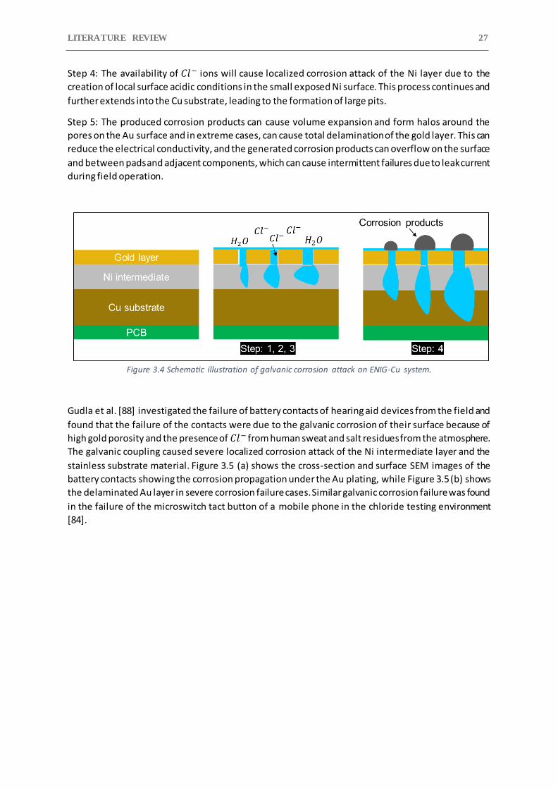
LITERATURE REVIEW 27
Step 4: The availability of 𝐶𝑙− ions will cause localized corrosion attack of the Ni layer due to the
creation of local surface acidic conditions in the small exposed Ni surface. This process continues and
further extends into the Cu substrate, leading to the formation of large pits.
Step 5: The produced corrosion products can cause volume expansion and form halos around the
pores on the Au surface and in extreme cases, can cause total delamination of the gold layer. This can
reduce the electrical conductivity, and the generated corrosion products can overflow on the surface
and between pads and adjacent components, which can cause intermittent failures due to leak current
during field operation.
Figure 3.4 Schematic illustration of galvanic corrosion attack on ENIG-Cu system.
Gudla et al. [88] investigated the failure of battery contacts of hearing aid devices from the field and
found that the failure of the contacts were due to the galvanic corrosion of their surface because of
high gold porosity and the presence of 𝐶𝑙− from human sweat and salt residues from the atmosphere.
The galvanic coupling caused severe localized corrosion attack of the Ni intermediate layer and the
stainless substrate material. Figure 3.5 (a) shows the cross-section and surface SEM images of the
battery contacts showing the corrosion propagation under the Au plating, while Figure 3.5 (b) shows
the delaminated Au layer in severe corrosion failure cases. Similar galvanic corrosion failure was found
in the failure of the microswitch tact button of a mobile phone in the chloride testing environment
[84].
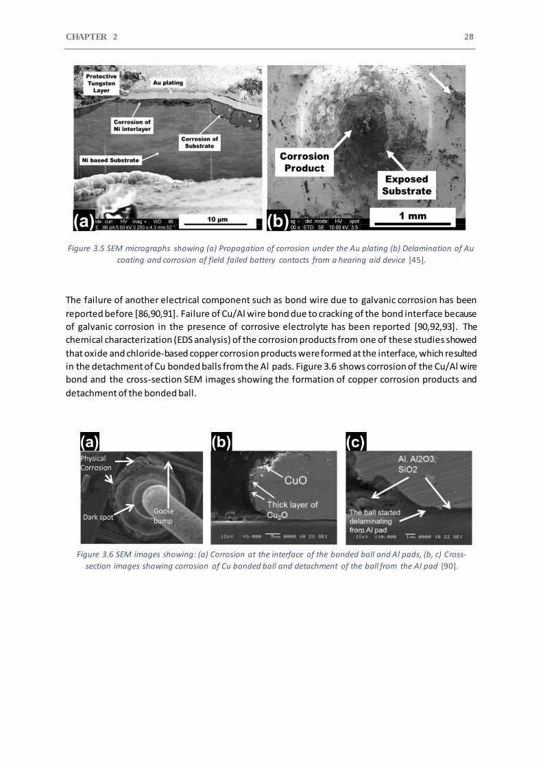
CHAPTER 2 28
Figure 3.5 SEM micrographs showing (a) Propagation of corrosion under the Au plating (b) Delamination of Au
coating and corrosion of field failed battery contacts from a hearing aid device [45].
The failure of another electrical component such as bond wire due to galvanic corrosion has been
reported before [86,90,91]. Failure of Cu/Al wire bond due to cracking of the bond interface because
of galvanic corrosion in the presence of corrosive electrolyte has been reported [90,92,93]. The
chemical characterization (EDS analysis) of the corrosion products from one of these studies showed
that oxide and chloride-based copper corrosion products were formed at the interface, which resulted
in the detachment of Cu bonded balls from the Al pads. Figure 3.6 shows corrosion of the Cu/Al wire
bond and the cross-section SEM images showing the formation of copper corrosion products and
detachment of the bonded ball.
Figure 3.6 SEM images showing: (a) Corrosion at the interface of the bonded ball and Al pads, (b, c) Cross-
section images showing corrosion of Cu bonded ball and detachment of the ball from the Al pad [90].
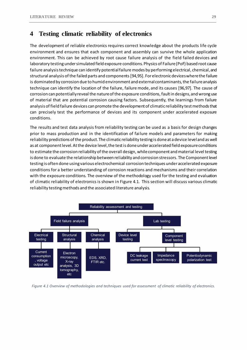
LITERATURE REVIEW 29
4 Testing climatic reliability of electronics
The development of reliable electronics requires correct knowledge about the products life cycle
environment and ensures that each component and assembly can survive the whole application
environment. This can be achieved by root cause failure analysis of the field failed devices and
laboratory testing under simulated field exposure conditions. Physics of Failure (PoF) based root cause
failure analysis technique can identify potential failure modes by performing electrical, chemical, and
structural analysis of the failed parts and components [94,95]. For electronic devices where the failure
is dominated by corrosion due to humid environment and external contaminants, the failure analysis
technique can identify the location of the failure, failure mode, and its causes [96,97]. The cause of
corrosion can potentially reveal the nature of the exposure conditions, fault in designs, and wrong use
of material that are potential corrosion causing factors. Subsequently, the learnings from failure
analysis of field failure devices can promote the development of climatic reliability test methods that
can precisely test the performance of devices and its component under accelerated exposure
conditions.
The results and test data analysis from reliability testing can be used as a basis for design changes
prior to mass production and in the identification of fai lure models and parameters for making
reliability predictions of the product. The climatic reliability testing is done at a device level and as well
as at component level. At the device level, the test is done under accelerated field exposure conditions
to estimate the corrosion reliability of the overall design, while component and material level testing
is done to evaluate the relationship between reliability and corrosion stressors. The Component level
testing is often done using various electrochemical corrosion techniques under accelerated exposure
conditions for a better understanding of corrosion reactions and mechanisms and their correlation
with the exposure conditions. The overview of the methodology used for the testing and evaluation
of climatic reliability of electronics is shown in Figure 4.1. This section will discuss various climatic
reliability testing methods and the associated literature analysis.
Figure 4.1 Overview of methodologies and techniques used for assessment of climatic reliability of electronics.
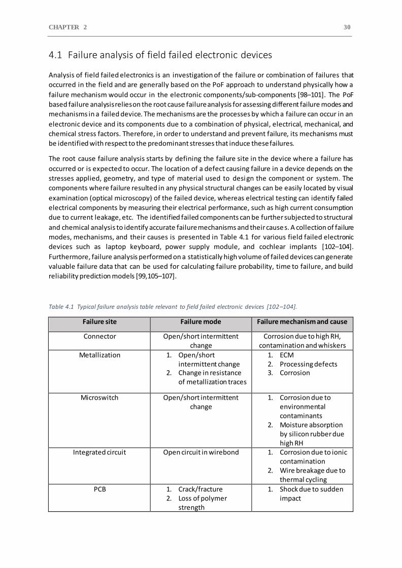
CHAPTER 2 30
4.1 Failure analysis of field failed electronic devices
Analysis of field failed electronics is an investigation of the failure or combination of failures that
occurred in the field and are generally based on the PoF approach to understand physically how a
failure mechanism would occur in the electronic components/sub-components [98–101]. The PoF
based failure analysis relies on the root cause failure analysis for assessing different failure modes and
mechanisms in a failed device. The mechanisms are the processes by which a failure can occur in an
electronic device and its components due to a combination of physical, electrical, mechanical, and
chemical stress factors. Therefore, in order to understand and prevent failure, its mechanisms must
be identified with respect to the predominant stresses that induce these failures.
The root cause failure analysis starts by defining the failure site in the device where a failure has
occurred or is expected to occur. The location of a defect causing failure in a device depends on the
stresses applied, geometry, and type of material used to desi gn the component or system. The
components where failure resulted in any physical structural changes can be easily located by visual
examination (optical microscopy) of the failed device, whereas electrical testing can identify failed
electrical components by measuring their electrical performance, such as high current consumption
due to current leakage, etc. The identified failed components can be further subjected to structural
and chemical analysis to identify accurate failure mechanisms and their cause s. A collection of failure
modes, mechanisms, and their causes is presented in Table 4.1 for various field failed electronic
devices such as laptop keyboard, power supply module, and cochlear implants [102–104].
Furthermore, failure analysis performed on a statistically high volume of failed devices can generate
valuable failure data that can be used for calculating failure probability, time to failure, and build
reliability prediction models [99,105–107].
Table 4.1 Typical failure analysis table relevant to field failed electronic devices [102–104].
Failure site Failure mode Failure mechanism and cause
Connector Open/short intermittent change
Corrosion due to high RH, contamination and whiskers
Metallization 1. Open/short intermittent change
2. Change in resistance of metallization traces
1. ECM 2. Processing defects 3. Corrosion
Microswitch Open/short intermittent change
1. Corrosion due to environmental contaminants
2. Moisture absorption by silicon rubber due high RH
Integrated circuit Open circuit in wirebond 1. Corrosion due to ionic contamination
2. Wire breakage due to thermal cycling
PCB
1. Crack/fracture 2. Loss of polymer
strength
1. Shock due to sudden impact
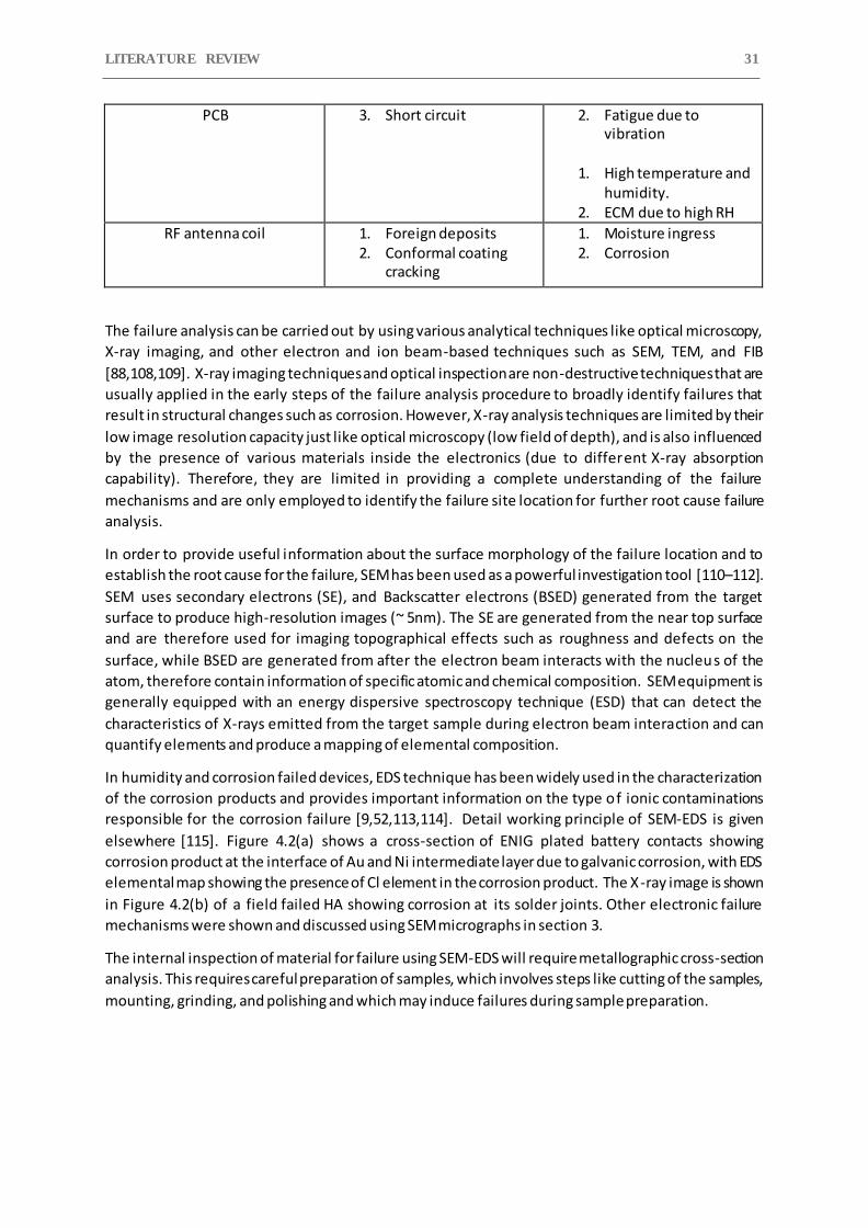
LITERATURE REVIEW 31
PCB 3. Short circuit 2. Fatigue due to vibration
1. High temperature and
humidity. 2. ECM due to high RH
RF antenna coil 1. Foreign deposits 2. Conformal coating
cracking
1. Moisture ingress 2. Corrosion
The failure analysis can be carried out by using various analytical techniques like optical microscopy,
X-ray imaging, and other electron and ion beam-based techniques such as SEM, TEM, and FIB
[88,108,109]. X-ray imaging techniques and optical inspection are non-destructive techniques that are
usually applied in the early steps of the failure analysis procedure to broadly identify failures that
result in structural changes such as corrosion. However, X-ray analysis techniques are limited by their
low image resolution capacity just like optical microscopy (low field of depth), and is also influenced
by the presence of various materials inside the electronics (due to different X-ray absorption
capability). Therefore, they are limited in providing a complete understanding of the failure
mechanisms and are only employed to identify the failure site location for further root cause failure
analysis.
In order to provide useful information about the surface morphology of the failure location and to
establish the root cause for the failure, SEM has been used as a powerful investigation tool [110–112].
SEM uses secondary electrons (SE), and Backscatter electrons (BSED) generated from the target
surface to produce high-resolution images (~ 5nm). The SE are generated from the near top surface
and are therefore used for imaging topographical effects such as roughness and defects on the
surface, while BSED are generated from after the electron beam interacts with the nucleus of the
atom, therefore contain information of specific atomic and chemical composition. SEM equipment is
generally equipped with an energy dispersive spectroscopy technique (ESD) that can detect the
characteristics of X-rays emitted from the target sample during electron beam interaction and can
quantify elements and produce a mapping of elemental composition.
In humidity and corrosion failed devices, EDS technique has been widely used in the characterization
of the corrosion products and provides important information on the type of ionic contaminations
responsible for the corrosion failure [9,52,113,114]. Detail working principle of SEM-EDS is given
elsewhere [115]. Figure 4.2(a) shows a cross-section of ENIG plated battery contacts showing
corrosion product at the interface of Au and Ni intermediate layer due to galvanic corrosion, with EDS
elemental map showing the presence of Cl element in the corrosion product. The X-ray image is shown
in Figure 4.2(b) of a field failed HA showing corrosion at its solder joints. Other electronic failure
mechanisms were shown and discussed using SEM micrographs in section 3.
The internal inspection of material for failure using SEM-EDS will require metallographic cross-section
analysis. This requires careful preparation of samples, which involves steps like cutting of the samples,
mounting, grinding, and polishing and which may induce failures during sample preparation.

CHAPTER 2 32
Figure 4.2 (a) Cross-section BSED image and the EDS elemental maps for corrosion failed battery contact [45],
(b) X-ray imaging of the field failed HA device showing corrosion on its solder joint.
4.2 Device level testing
Although numerous types of device-level testing are done to identify electrical, mechanical, chemical,
and thermal induced failures in electronics, this section only discusses the subject: device -level testing
of electronics for evaluating the corrosion reliability of electronics. Corrosion is the occurrence of
chemical and electrochemical reactions between the material, mostly metals, due to its interaction
with its environment that produces a deterioration of the material and its properties. The corrosion
process eventually develops into failure, and its rate depends on the severity of its environmental
factors such as humidity, temperature, and contamination level, as mentioned throughout previous
sections. Therefore, in order to test the corrosion reliability of electronic products, the corrosion test
methods should be designed to create field exposure testing conditions and with the ability to control
and modify different test parameters. In general, the device-level testing is done under accelerated
conditions by increasing the level of corrosion stressors to stimulate product degradation processes
and quickly estimate its performance and reliability [116]. However, some studies have shown that
the failure mechanism of some electronic components changed under excessive accelerated stress
levels, and therefore, it becomes important to ensure that on increasing the stress level only
accelerates the product failure rate and doesn’t change the failure mechanism [117,118].
Different corrosion test methods are available for reliability and quality assessment of electronic
products under simulated corrosive environments that electronic devices are expected to be exposed
to during field operation but at an accelerated rate. Some of the most used accelerated corrosion
testings for an electronic device are high humidity and temperature, mixed flowing gas, dust, salt
spray, and flower of sulfur test. All these tests are performed inside a chamber within which the
corrosive environments can be created. Some of the chambers used in these tests are fully automated
(Figure 4.3) and are popularly used for scientific corrosion failure investigation.
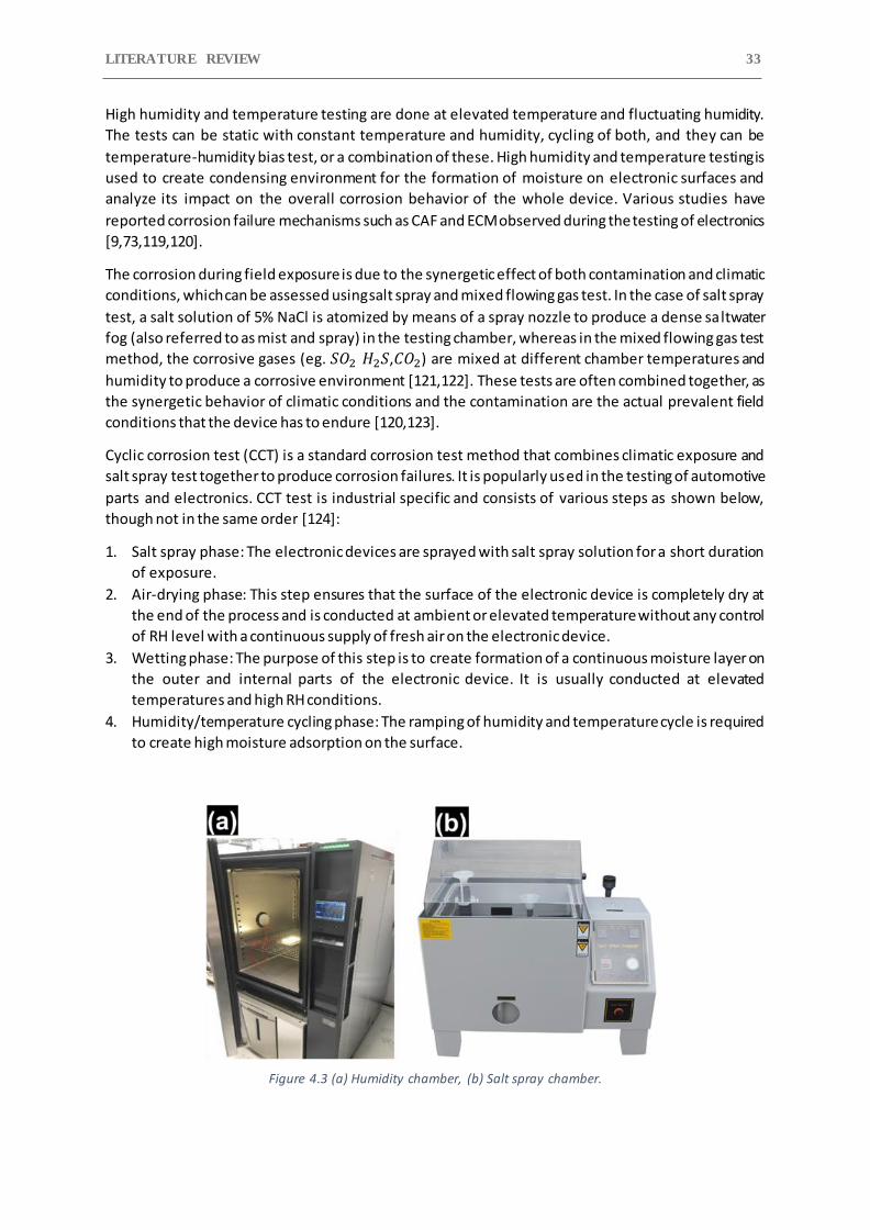
LITERATURE REVIEW 33
High humidity and temperature testing are done at elevated temperature and fluctuating humidity.
The tests can be static with constant temperature and humidity, cycling of both, and they can be
temperature-humidity bias test, or a combination of these. High humidity and temperature testing is
used to create condensing environment for the formation of moisture on electronic surfaces and
analyze its impact on the overall corrosion behavior of the whole device. Various studies have
reported corrosion failure mechanisms such as CAF and ECM observed during the testing of electronics
[9,73,119,120].
The corrosion during field exposure is due to the synergetic effect of both contamination and climatic
conditions, which can be assessed using salt spray and mixed flowing gas test. In the case of salt spray
test, a salt solution of 5% NaCl is atomized by means of a spray nozzle to produce a dense saltwater
fog (also referred to as mist and spray) in the testing chamber, whereas in the mixed flowing gas test
method, the corrosive gases (eg. 𝑆𝑂2 𝐻2𝑆,𝐶𝑂2) are mixed at different chamber temperatures and
humidity to produce a corrosive environment [121,122]. These tests are often combined together, as
the synergetic behavior of climatic conditions and the contamination are the actual prevalent field
conditions that the device has to endure [120,123].
Cyclic corrosion test (CCT) is a standard corrosion test method that combines climatic exposure and
salt spray test together to produce corrosion failures. It is popularly used in the testing of automotive
parts and electronics. CCT test is industrial specific and consists of various steps as shown below,
though not in the same order [124]:
1. Salt spray phase: The electronic devices are sprayed with salt spray solution for a short duration
of exposure.
2. Air-drying phase: This step ensures that the surface of the electronic device is completely dry at
the end of the process and is conducted at ambient or elevated temperature without any control
of RH level with a continuous supply of fresh air on the electronic device.
3. Wetting phase: The purpose of this step is to create formation of a continuous moisture layer on
the outer and internal parts of the electronic device. It is usually conducted at elevated
temperatures and high RH conditions.
4. Humidity/temperature cycling phase: The ramping of humidity and temperature cycle is required
to create high moisture adsorption on the surface.
Figure 4.3 (a) Humidity chamber, (b) Salt spray chamber.
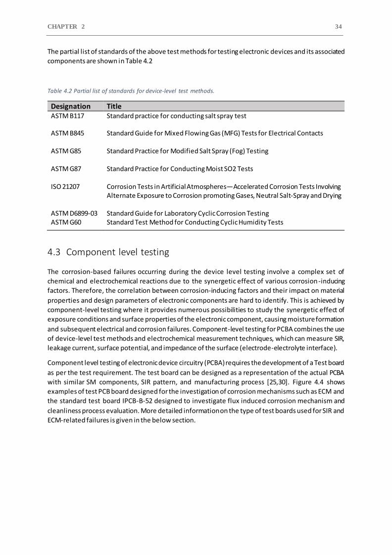
CHAPTER 2 34
The partial list of standards of the above test methods for testing electronic devices and its associated
components are shown in Table 4.2
Table 4.2 Partial list of standards for device-level test methods.
Designation Title ASTM B117 Standard practice for conducting salt spray test
ASTM B845 Standard Guide for Mixed Flowing Gas (MFG) Tests for Electrical Contacts
ASTM G85 Standard Practice for Modified Salt Spray (Fog) Testing
ASTM G87 Standard Practice for Conducting Moist SO2 Tests
ISO 21207 Corrosion Tests in Artificial Atmospheres—Accelerated Corrosion Tests Involving
Alternate Exposure to Corrosion promoting Gases, Neutral Salt-Spray and Drying
ASTM D6899-03 Standard Guide for Laboratory Cyclic Corrosion Testing ASTM G60 Standard Test Method for Conducting Cyclic Humidity Tests
4.3 Component level testing
The corrosion-based failures occurring during the device level testing involve a complex set of
chemical and electrochemical reactions due to the synergetic effect of various corrosion-inducing
factors. Therefore, the correlation between corrosion-inducing factors and their impact on material
properties and design parameters of electronic components are hard to identify. This is achieved by
component-level testing where it provides numerous possibilities to study the synergetic effect of
exposure conditions and surface properties of the electronic component, causing moisture formation
and subsequent electrical and corrosion failures. Component-level testing for PCBA combines the use
of device-level test methods and electrochemical measurement techniques, which can measure SIR,
leakage current, surface potential, and impedance of the surface (electrode-electrolyte interface).
Component level testing of electronic device circuitry (PCBA) requires the development of a Test board
as per the test requirement. The test board can be designed as a representation of the actual PCBA
with similar SM components, SIR pattern, and manufacturing process [25,30]. Figure 4.4 shows
examples of test PCB board designed for the investigation of corrosion mechanisms such as ECM and
the standard test board IPCB-B-52 designed to investigate flux induced corrosion mechanism and
cleanliness process evaluation. More detailed information on the type of test boards used for SIR and
ECM-related failures is given in the below section.
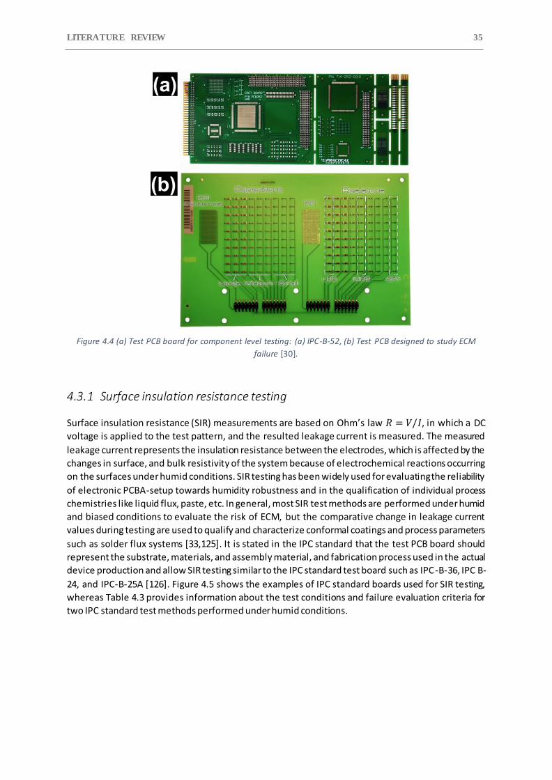
LITERATURE REVIEW 35
Figure 4.4 (a) Test PCB board for component level testing: (a) IPC-B-52, (b) Test PCB designed to study ECM
failure [30].
4.3.1 Surface insulation resistance testing
Surface insulation resistance (SIR) measurements are based on Ohm’s law 𝑅 = 𝑉/𝐼, in which a DC
voltage is applied to the test pattern, and the resulted leakage current is measured. The measured
leakage current represents the insulation resistance between the electrodes, which is affected by the
changes in surface, and bulk resistivity of the system because of electrochemical reactions occurring
on the surfaces under humid conditions. SIR testing has been widely used for evaluating the reliability
of electronic PCBA-setup towards humidity robustness and in the qualification of individual process
chemistries like liquid flux, paste, etc. In general, most SIR test methods are performed under humid
and biased conditions to evaluate the risk of ECM, but the comparative change in leakage current
values during testing are used to qualify and characterize conformal coatings and process parameters
such as solder flux systems [33,125]. It is stated in the IPC standard that the test PCB board should
represent the substrate, materials, and assembly material, and fabrication process used in the actual
device production and allow SIR testing similar to the IPC standard test board such as IPC-B-36, IPC B-
24, and IPC-B-25A [126]. Figure 4.5 shows the examples of IPC standard boards used for SIR testing,
whereas Table 4.3 provides information about the test conditions and failure evaluation criteria for
two IPC standard test methods performed under humid conditions.
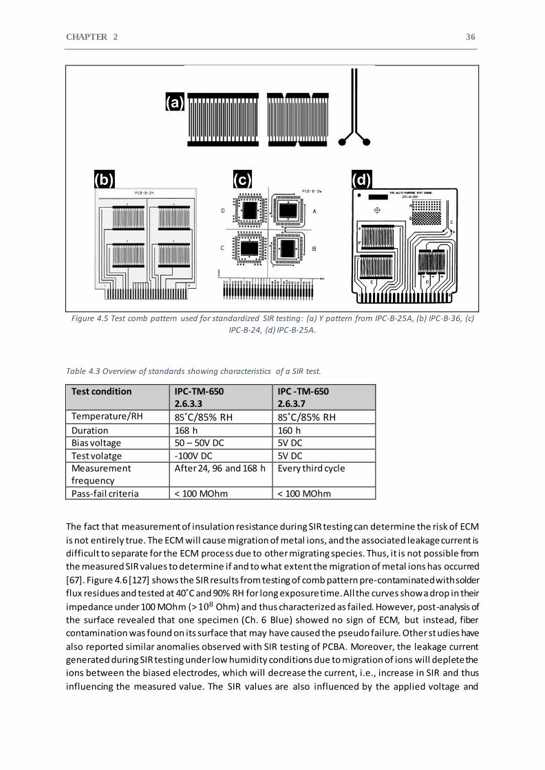
CHAPTER 2 36
Figure 4.5 Test comb pattern used for standardized SIR testing: (a) Y pattern from IPC-B-25A, (b) IPC-B-36, (c)
IPC-B-24, (d) IPC-B-25A.
Table 4.3 Overview of standards showing characteristics of a SIR test.
Test condition IPC-TM-650 2.6.3.3
IPC -TM-650 2.6.3.7
Temperature/RH 85˚C/85% RH 85˚C/85% RH
Duration 168 h 160 h Bias voltage 50 – 50V DC 5V DC
Test volatge -100V DC 5V DC Measurement frequency
After 24, 96 and 168 h Every third cycle
Pass-fail criteria < 100 MOhm < 100 MOhm
The fact that measurement of insulation resistance during SIR testing can determine the risk of ECM
is not entirely true. The ECM will cause migration of metal ions, and the associated leakage current is
difficult to separate for the ECM process due to other migrating species. Thus, it is not possible from
the measured SIR values to determine if and to what extent the migration of metal ions has occurred
[67]. Figure 4.6 [127] shows the SIR results from testing of comb pattern pre-contaminated with solder
flux residues and tested at 40˚C and 90% RH for long exposure time. All the curves show a drop in their
impedance under 100 MOhm (> 108 Ohm) and thus characterized as failed. However, post-analysis of
the surface revealed that one specimen (Ch. 6 Blue) showed no sign of ECM, but instead, fiber
contamination was found on its surface that may have caused the pseudo failure. Other studies have
also reported similar anomalies observed with SIR testing of PCBA. Moreover, the leakage current
generated during SIR testing under low humidity conditions due to migration of ions will deplete the
ions between the biased electrodes, which will decrease the current, i.e., increase in SIR and thus
influencing the measured value. The SIR values are also influenced by the applied voltage and
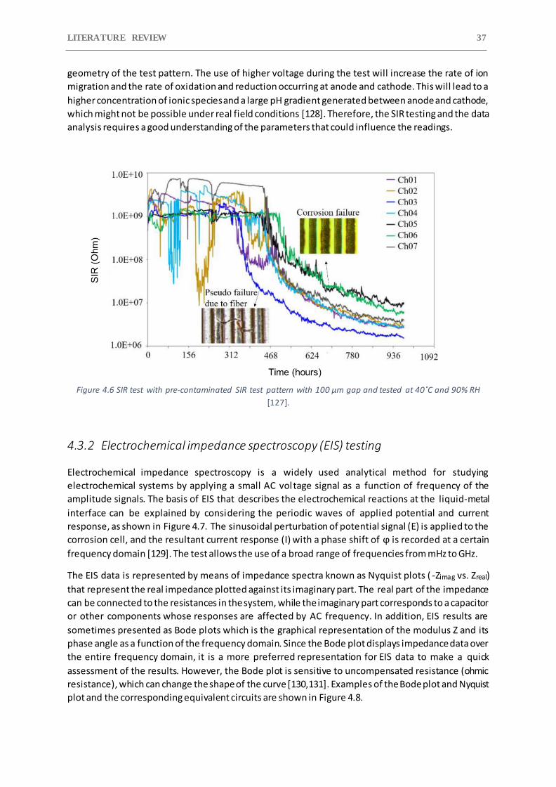
LITERATURE REVIEW 37
geometry of the test pattern. The use of higher voltage during the test will increase the rate of ion
migration and the rate of oxidation and reduction occurring at anode and cathode. This will lead to a
higher concentration of ionic species and a large pH gradient generated between anode and cathode,
which might not be possible under real field conditions [128]. Therefore, the SIR testing and the data
analysis requires a good understanding of the parameters that could influence the readings.
Figure 4.6 SIR test with pre-contaminated SIR test pattern with 100 μm gap and tested at 40˚C and 90% RH
[127].
4.3.2 Electrochemical impedance spectroscopy (EIS) testing
Electrochemical impedance spectroscopy is a widely used analytical method for studying
electrochemical systems by applying a small AC voltage signal as a function of frequency of the
amplitude signals. The basis of EIS that describes the electrochemical reactions at the liquid-metal
interface can be explained by considering the periodic waves of applied potential and current
response, as shown in Figure 4.7. The sinusoidal perturbation of potential signal (E) is applied to the
corrosion cell, and the resultant current response (I) with a phase shift of ϕ is recorded at a certain
frequency domain [129]. The test allows the use of a broad range of frequencies from mHz to GHz.
The EIS data is represented by means of impedance spectra known as Nyquist plots ( -Zimag vs. Zreal)
that represent the real impedance plotted against its imaginary part. The real part of the impedance
can be connected to the resistances in the system, while the imaginary part corresponds to a capacitor
or other components whose responses are affected by AC frequency. In addition, EIS results are
sometimes presented as Bode plots which is the graphical representation of the modulus Z and its
phase angle as a function of the frequency domain. Since the Bode plot displays impedance data over
the entire frequency domain, it is a more preferred representation for EIS data to make a quick
assessment of the results. However, the Bode plot is sensitive to uncompensated resistance (ohmic
resistance), which can change the shape of the curve [130,131]. Examples of the Bode plot and Nyquist
plot and the corresponding equivalent circuits are shown in Figure 4.8.
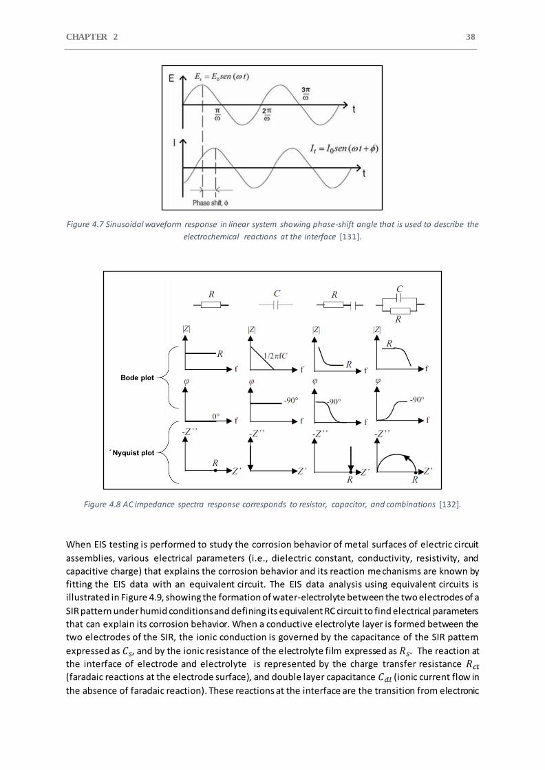
CHAPTER 2 38
Figure 4.7 Sinusoidal waveform response in linear system showing phase-shift angle that is used to describe the
electrochemical reactions at the interface [131].
Figure 4.8 AC impedance spectra response corresponds to resistor, capacitor, and combinations [132].
When EIS testing is performed to study the corrosion behavior of metal surfaces of electric circuit
assemblies, various electrical parameters (i.e., dielectric constant, conductivity, resistivity, and
capacitive charge) that explains the corrosion behavior and its reaction me chanisms are known by
fitting the EIS data with an equivalent circuit. The EIS data analysis using equivalent circuits is
illustrated in Figure 4.9, showing the formation of water-electrolyte between the two electrodes of a
SIR pattern under humid conditions and defining its equivalent RC circuit to find electrical parameters
that can explain its corrosion behavior. When a conductive electrolyte layer is formed between the
two electrodes of the SIR, the ionic conduction is governed by the capacitance of the SIR pattern
expressed as 𝐶𝑠, and by the ionic resistance of the electrolyte film expressed as 𝑅𝑠. The reaction at
the interface of electrode and electrolyte is represented by the charge transfer resistance 𝑅𝑐𝑡
(faradaic reactions at the electrode surface), and double layer capacitance 𝐶𝑑𝑙 (ionic current flow in
the absence of faradaic reaction). These reactions at the interface are the transition from electronic
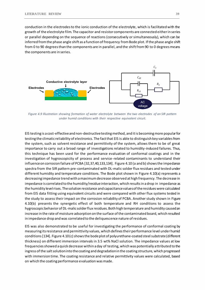
LITERATURE REVIEW 39
conduction in the electrodes to the ionic conduction of the electrolyte, which is facilitated with the
growth of the electrolyte film. The capacitor and resistor components are connected either in series
or parallel depending on the sequence of reactions (consecutively or simultaneously), which can be
inferred from the phase angle shift as a function of frequency from Bode plot. If the phase angle shift
from 0 to 90 degrees than the components are in parallel, and the shift from 90 to 0 degrees means
the components are in series.
Figure 4.9 Illustration showing formation of water electrolyte between the two electrodes of an SIR pattern
under humid conditions with their respective equivalent circuit.
EIS testing is a cost-effective and non-destructive testing method, and it is becoming more popular for
testing the climatic reliability of electronics. The fact that EIS is able to distinguish key variables from
the system, such as solvent resistance and permittivity of the system, allows them to be of great
importance to carry out a broad range of investigations related to humidity-induced failures. Thus,
this technique has been used for the performance evaluation of conformal coatings and in the
investigation of hygroscopicity of process and service-related contaminants to understand their
influence on corrosion failure of PCBA [32,37,40,133,134]. Figure 4.10 (a and b) shows the impedance
spectra from the SIR pattern pre-contaminated with DL-malic solder flux residues and tested under
different humidity and temperature conditions. The Bode plot shown in Figure 4.10(a) represents a
decreasing impedance trend with a maximum decrease observed at high frequency. The decrease in
impedance is correlated to the humidity/residue interaction, which results in a drop in impedance as
the humidity level rises. The solution resistance and capacitance values of the residues were calculated
from EIS data fitting using equivalent circuits and were compared with other flux systems tested in
the study to assess their impact on the corrosion reliability of PCBA. Another study shown in Figure
4.10(b) presents the synergetic effect of both temperature and RH conditions to assess the
hygroscopic behavior of DL-malic solder flux residues. Both high temperature and humidity caused an
increase in the rate of moisture adsorption on the surface of the contaminated board, which resulted
in impedance drop and was correlated to the deliquescence nature of residues.
EIS was also demonstrated to be useful for investigating the performance of conformal coating by
measuring its resistance and permittivity values, which defines their performance level under humid
conditions [134]. Figure 4.10 (c) shows the bode plot of polyurethane-coated steel substrate (different
thickness) on different immersion intervals in 3.5 wt% NaCl solution. The impedance values at low
frequencies showed a quick decrease within a day of testing, which was potentially attributed to the
ingress of the salt solution into the coating and degradation in the coating structure, which progressed
with immersion time. The coating resistance and relative permittivity values were calculated, based
on which the coating performance evaluation was made.
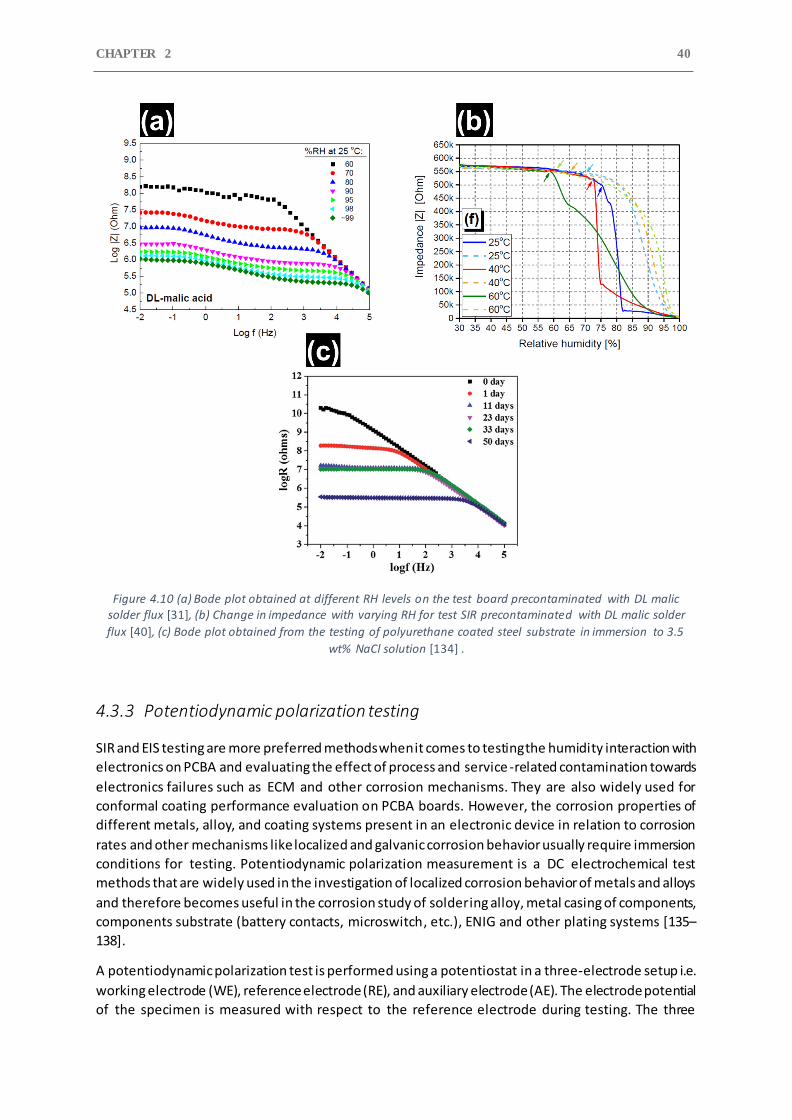
CHAPTER 2 40
Figure 4.10 (a) Bode plot obtained at different RH levels on the test board precontaminated with DL malic solder flux [31], (b) Change in impedance with varying RH for test SIR precontaminated with DL malic solder
flux [40], (c) Bode plot obtained from the testing of polyurethane coated steel substrate in immersion to 3.5
wt% NaCl solution [134] .
4.3.3 Potentiodynamic polarization testing
SIR and EIS testing are more preferred methods when it comes to testing the humidity interaction with
electronics on PCBA and evaluating the effect of process and service -related contamination towards
electronics failures such as ECM and other corrosion mechanisms. They are also widely used for
conformal coating performance evaluation on PCBA boards. However, the corrosion properties of
different metals, alloy, and coating systems present in an electronic device in relation to corrosion
rates and other mechanisms like localized and galvanic corrosion behavior usually require immersion
conditions for testing. Potentiodynamic polarization measurement is a DC electrochemical test
methods that are widely used in the investigation of localized corrosion behavior of metals and alloys
and therefore becomes useful in the corrosion study of soldering alloy, metal casing of components,
components substrate (battery contacts, microswitch, etc.), ENIG and other plating systems [135–
138].
A potentiodynamic polarization test is performed using a potentiostat in a three-electrode setup i.e.
working electrode (WE), reference electrode (RE), and auxiliary electrode (AE). The electrode potential
of the specimen is measured with respect to the reference electrode during testing. The three
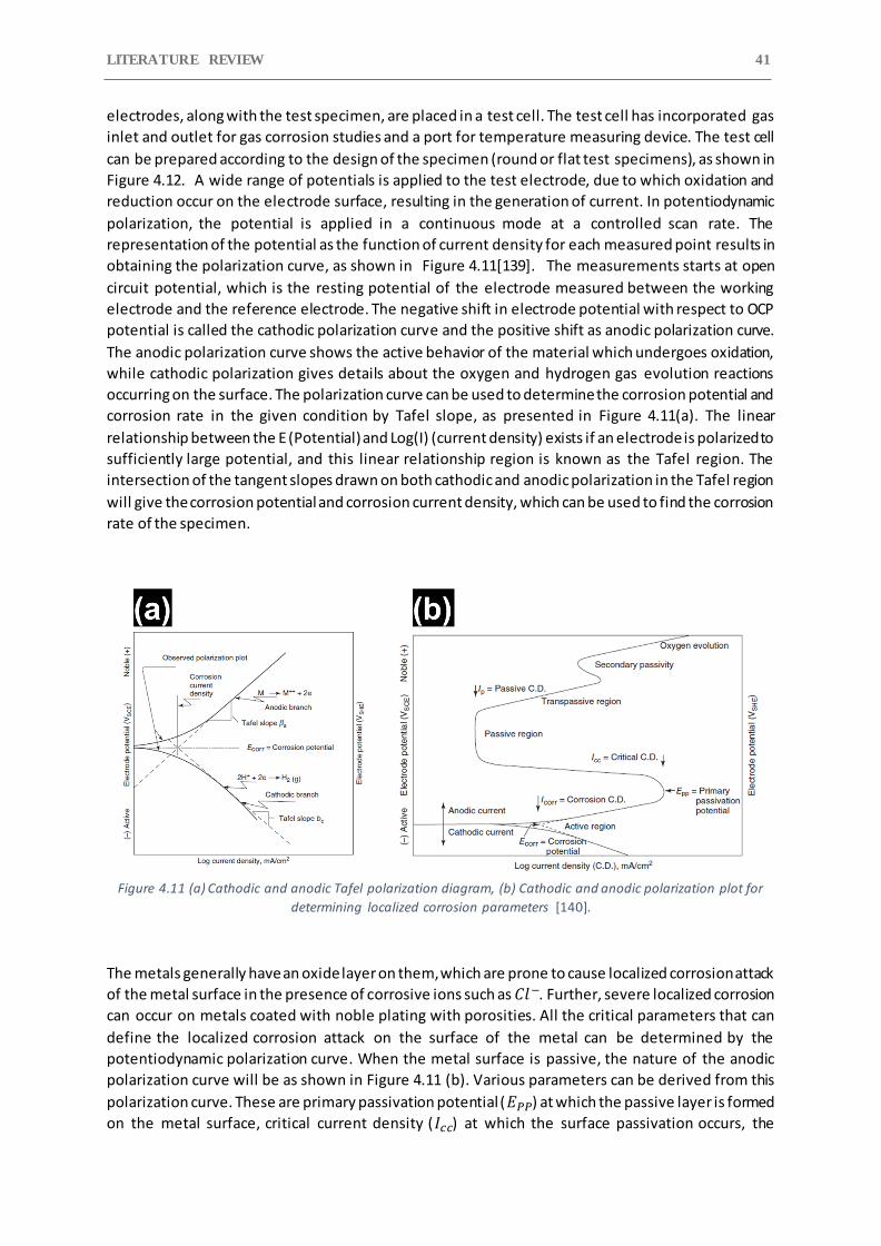
LITERATURE REVIEW 41
electrodes, along with the test specimen, are placed in a test cell. The test cell has incorporated gas
inlet and outlet for gas corrosion studies and a port for temperature measuring device. The test cell
can be prepared according to the design of the specimen (round or flat test specimens), as shown in
Figure 4.12. A wide range of potentials is applied to the test electrode, due to which oxidation and
reduction occur on the electrode surface, resulting in the generation of current. In potentiodynamic
polarization, the potential is applied in a continuous mode at a controlled scan rate. The
representation of the potential as the function of current density for each measured point results in
obtaining the polarization curve, as shown in Figure 4.11[139]. The measurements starts at open
circuit potential, which is the resting potential of the electrode measured between the working
electrode and the reference electrode. The negative shift in electrode potential with respect to OCP
potential is called the cathodic polarization curve and the positive shift as anodic polarization curve.
The anodic polarization curve shows the active behavior of the material which undergoes oxidation,
while cathodic polarization gives details about the oxygen and hydrogen gas evolution reactions
occurring on the surface. The polarization curve can be used to determine the corrosion potential and
corrosion rate in the given condition by Tafel slope, as presented in Figure 4.11(a). The linear
relationship between the E (Potential) and Log(I) (current density) exists if an electrode is polarized to
sufficiently large potential, and this linear relationship region is known as the Tafel region. The
intersection of the tangent slopes drawn on both cathodic and anodic polarization in the Tafel region
will give the corrosion potential and corrosion current density, which can be used to find the corrosion
rate of the specimen.
Figure 4.11 (a) Cathodic and anodic Tafel polarization diagram, (b) Cathodic and anodic polarization plot for
determining localized corrosion parameters [140].
The metals generally have an oxide layer on them, which are prone to cause localized corrosion attack
of the metal surface in the presence of corrosive ions such as 𝐶𝑙−. Further, severe localized corrosion
can occur on metals coated with noble plating with porosities. All the critical parameters that can
define the localized corrosion attack on the surface of the metal can be determined by the
potentiodynamic polarization curve. When the metal surface is passive, the nature of the anodic
polarization curve will be as shown in Figure 4.11 (b). Various parameters can be derived from this
polarization curve. These are primary passivation potential (𝐸𝑃𝑃) at which the passive layer is formed
on the metal surface, critical current density (𝐼𝑐𝑐) at which the surface passivation occurs, the
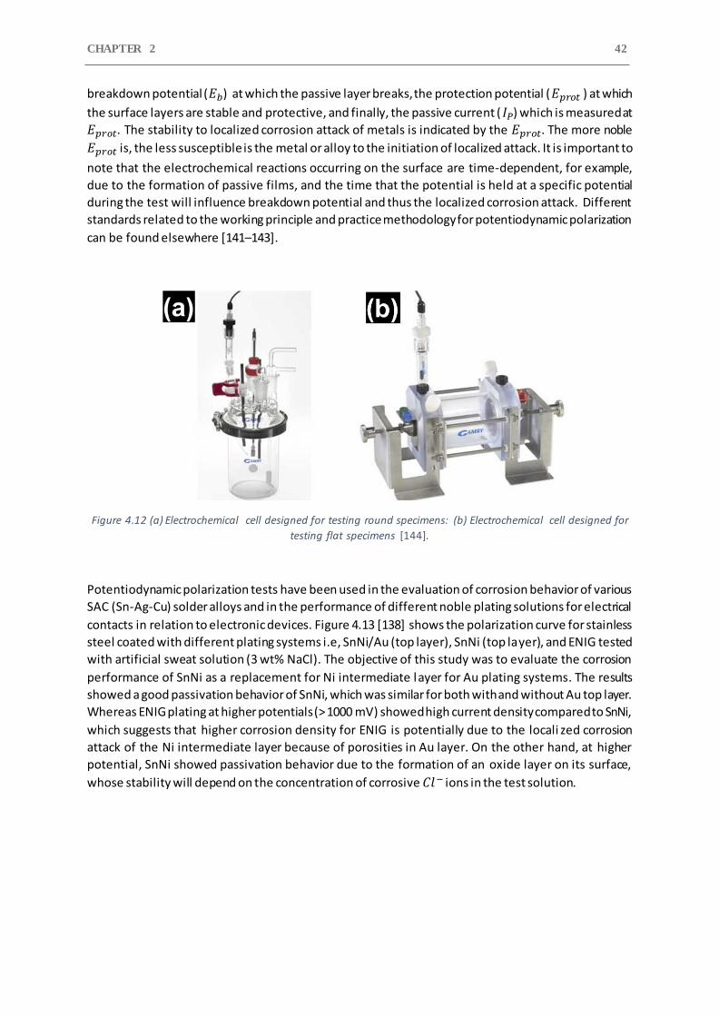
CHAPTER 2 42
breakdown potential (𝐸𝑏) at which the passive layer breaks, the protection potential (𝐸𝑝𝑟𝑜𝑡 ) at which
the surface layers are stable and protective, and finally, the passive current ( 𝐼𝑃) which is measured at
𝐸𝑝𝑟𝑜𝑡. The stability to localized corrosion attack of metals is indicated by the 𝐸𝑝𝑟𝑜𝑡. The more noble
𝐸𝑝𝑟𝑜𝑡 is, the less susceptible is the metal or alloy to the initiation of localized attack. It is important to
note that the electrochemical reactions occurring on the surface are time-dependent, for example,
due to the formation of passive films, and the time that the potential is held at a specific potential
during the test will influence breakdown potential and thus the localized corrosion attack. Different
standards related to the working principle and practice methodology for potentiodynamic polarization
can be found elsewhere [141–143].
Figure 4.12 (a) Electrochemical cell designed for testing round specimens: (b) Electrochemical cell designed for
testing flat specimens [144].
Potentiodynamic polarization tests have been used in the evaluation of corrosion behavior of various
SAC (Sn-Ag-Cu) solder alloys and in the performance of different noble plating solutions for electrical
contacts in relation to electronic devices. Figure 4.13 [138] shows the polarization curve for stainless
steel coated with different plating systems i.e, SnNi/Au (top layer), SnNi (top layer), and ENIG tested
with artificial sweat solution (3 wt% NaCl). The objective of this study was to evaluate the corrosion
performance of SnNi as a replacement for Ni intermediate layer for Au plating systems. The results
showed a good passivation behavior of SnNi, which was similar for both with and without Au top layer.
Whereas ENIG plating at higher potentials (> 1000 mV) showed high current density compared to SnNi,
which suggests that higher corrosion density for ENIG is potentially due to the locali zed corrosion
attack of the Ni intermediate layer because of porosities in Au layer. On the other hand, at higher
potential, SnNi showed passivation behavior due to the formation of an oxide layer on its surface,
whose stability will depend on the concentration of corrosive 𝐶𝑙− ions in the test solution.
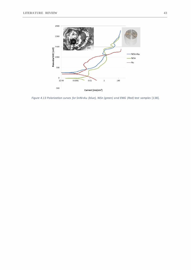
LITERATURE REVIEW 43
Figure 4.13 Polarization curves for SnNi+Au (blue), NiSn (green) and ENIG (Red) test samples [138].
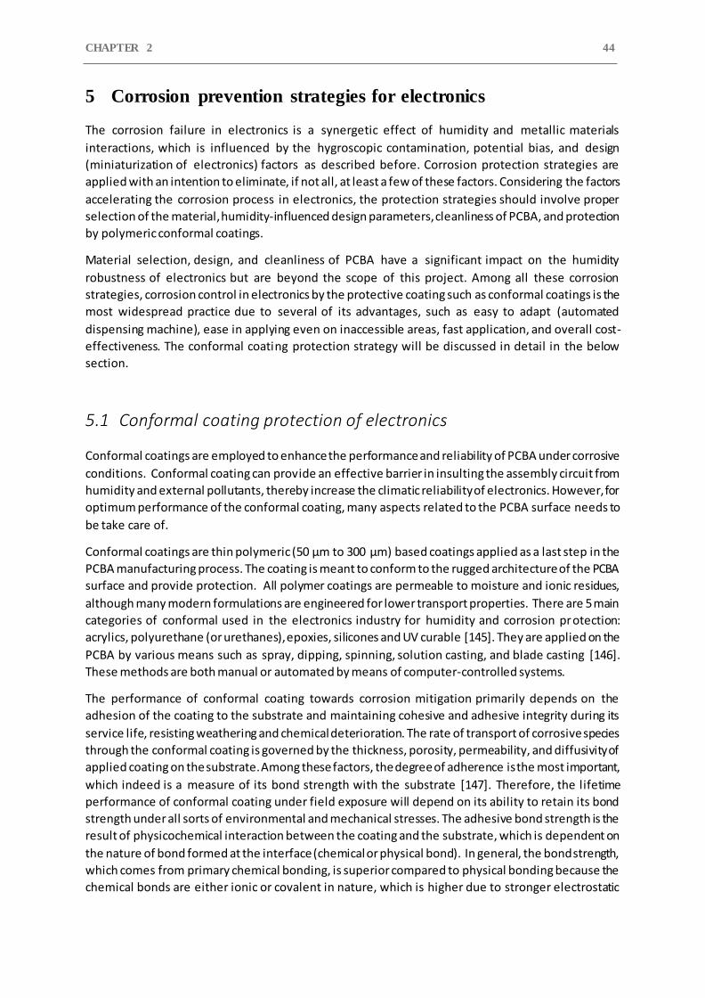
CHAPTER 2 44
5 Corrosion prevention strategies for electronics
The corrosion failure in electronics is a synergetic effect of humidity and metallic materials
interactions, which is influenced by the hygroscopic contamination, potential bias, and design
(miniaturization of electronics) factors as described before. Corrosion protection strategies are
applied with an intention to eliminate, if not all, at least a few of these factors. Considering the factors
accelerating the corrosion process in electronics, the protection strategies should involve proper
selection of the material, humidity-influenced design parameters, cleanliness of PCBA, and protection
by polymeric conformal coatings.
Material selection, design, and cleanliness of PCBA have a significant impact on the humidity
robustness of electronics but are beyond the scope of this project. Among all these corrosion
strategies, corrosion control in electronics by the protective coating such as conformal coatings is the
most widespread practice due to several of its advantages, such as easy to adapt (automated
dispensing machine), ease in applying even on inaccessible areas, fast application, and overall cost-
effectiveness. The conformal coating protection strategy will be discussed in detail in the below
section.
5.1 Conformal coating protection of electronics
Conformal coatings are employed to enhance the performance and reliability of PCBA under corrosive
conditions. Conformal coating can provide an effective barrier in insulting the assembly circuit from
humidity and external pollutants, thereby increase the climatic reliability of electronics. However, for
optimum performance of the conformal coating, many aspects related to the PCBA surface needs to
be take care of.
Conformal coatings are thin polymeric (50 μm to 300 μm) based coatings applied as a last step in the
PCBA manufacturing process. The coating is meant to conform to the rugged architecture of the PCBA
surface and provide protection. All polymer coatings are permeable to moisture and ionic residues,
although many modern formulations are engineered for lower transport properties. There are 5 main
categories of conformal used in the electronics industry for humidity and corrosion protection:
acrylics, polyurethane (or urethanes), epoxies, silicones and UV curable [145]. They are applied on the
PCBA by various means such as spray, dipping, spinning, solution casting, and blade casting [146].
These methods are both manual or automated by means of computer-controlled systems.
The performance of conformal coating towards corrosion mitigation primarily depends on the
adhesion of the coating to the substrate and maintaining cohesive and adhesive integrity during its
service life, resisting weathering and chemical deterioration. The rate of transport of corrosive species
through the conformal coating is governed by the thickness, porosity, permeability, and diffusivity of
applied coating on the substrate. Among these factors, the degree of adherence is the most important,
which indeed is a measure of its bond strength with the substrate [147]. Therefore, the lifetime
performance of conformal coating under field exposure will depend on its ability to retain its bond
strength under all sorts of environmental and mechanical stresses. The adhesive bond strength is the
result of physicochemical interaction between the coating and the substrate, which is dependent on
the nature of bond formed at the interface (chemical or physical bond). In general, the bond strength,
which comes from primary chemical bonding, is superior compared to physical bonding because the
chemical bonds are either ionic or covalent in nature, which is higher due to stronger electrostatic
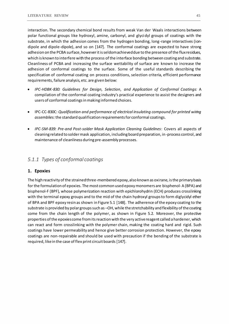
LITERATURE REVIEW 45
interaction. The secondary chemical bond results from weak Van der Waals interactions between
polar functional groups like hydroxyl, amine, carbonyl, and glyci dyl groups of coatings with the
substrate, in which the adhesion comes from the hydrogen bonding, long-range interactives (ion-
dipole and dipole-dipole), and so on [147]. The conformal coatings are expected to have strong
adhesion on the PCBA surface, however it is seldom achieved due to the presence of the flux residues,
which is known to interfere with the process of the interface bonding between coating and substrate.
Cleanliness of PCBA and increasing the surface wettability of surface are known to increase the
adhesion of conformal coatings to the surface. Some of the useful standards describing the
specification of conformal coating on process conditions, selection criteria, efficient performance
requirements, failure analysis, etc. are given below:
IPC-HDBK-830: Guidelines for Design, Selection, and Application of Conformal Coatings: A
compilation of the conformal coating industry's practical experience to assist the designers and
users of conformal coatings in making informed choices.
IPC-CC-830C: Qualification and performance of electrical insulating compound for printed wiring
assemblies: the standard qualification requirements for conformal coatings.
IPC-SM-839: Pre-and Post-solder Mask Application Cleaning Guidelines: Covers all aspects of
cleaning related to solder mask application, including board preparation, in-process control, and
maintenance of cleanliness during pre-assembly processes.
5.1.1 Types of conformal coatings
1. Epoxies
The high reactivity of the strained three-membered epoxy, also known as oxirane, is the primary basis
for the formulation of epoxies. The most common used epoxy monomers are bisphenol- A (BPA) and
bisphenol-F (BPF), whose polymerization reaction with epichlorohydrin (ECH) produces crosslinking
with the terminal epoxy groups and to the mid of the chain hydroxyl groups to form diglycidyl ether
of BPA and BPF epoxy resin as shown in Figure 5.1 [148]. The adherence of the epoxy coating to the
substrate is provided by polar groups such as –OH, while the stretchability and flexibility of the coating
come from the chain length of the polymer, as shown in Figure 5.2. Moreover, the protective
properties of the epoxies come from its reaction with the very active reagent called a hardener, which
can react and form crosslinking with the polymer chain, making the coating hard and rigid. Such
coatings have lower permeability and hence give better corrosion protection. However, the epoxy
coatings are non-repairable and should be used with precaution if the bending of the substrate is
required, like in the case of flex print circuit boards [147].
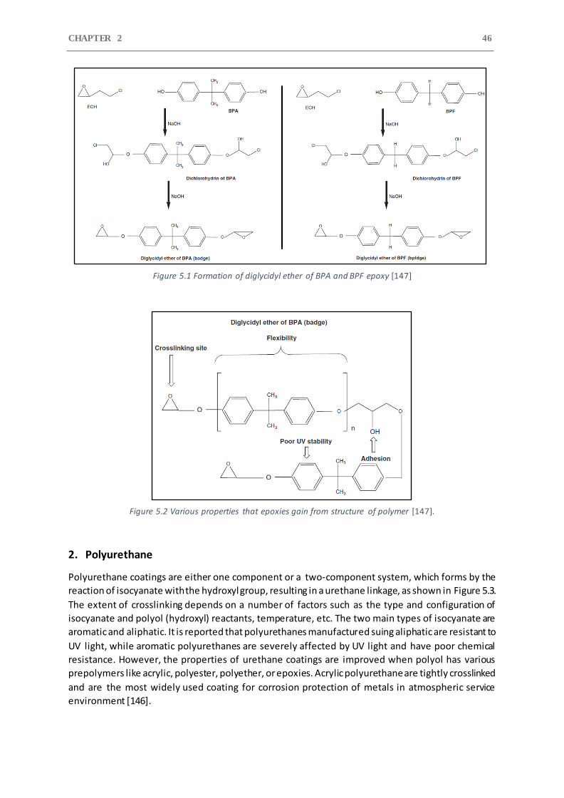
CHAPTER 2 46
Figure 5.1 Formation of diglycidyl ether of BPA and BPF epoxy [147]
Figure 5.2 Various properties that epoxies gain from structure of polymer [147].
2. Polyurethane
Polyurethane coatings are either one component or a two-component system, which forms by the
reaction of isocyanate with the hydroxyl group, resulting in a urethane linkage, as shown in Figure 5.3.
The extent of crosslinking depends on a number of factors such as the type and configuration of
isocyanate and polyol (hydroxyl) reactants, temperature, etc. The two main types of isocyanate are
aromatic and aliphatic. It is reported that polyurethanes manufactured suing aliphatic are resistant to
UV light, while aromatic polyurethanes are severely affected by UV light and have poor chemical
resistance. However, the properties of urethane coatings are improved when polyol has various
prepolymers like acrylic, polyester, polyether, or epoxies. Acrylic polyurethane are tightly crosslinked
and are the most widely used coating for corrosion protection of metals in atmospheric service
environment [146].
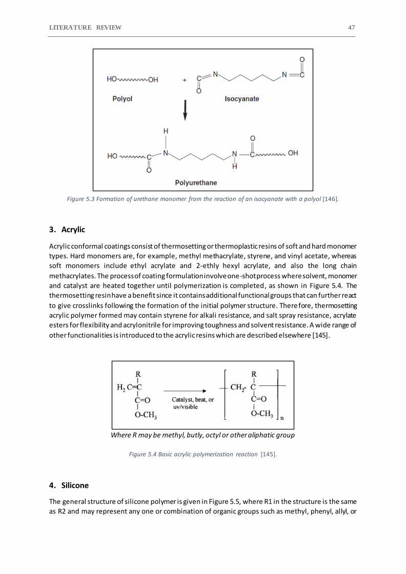
LITERATURE REVIEW 47
Figure 5.3 Formation of urethane monomer from the reaction of an isocyanate with a polyol [146].
3. Acrylic
Acrylic conformal coatings consist of thermosetting or thermoplastic resins of soft and hard monomer
types. Hard monomers are, for example, methyl methacrylate, styrene, and vinyl acetate, whereas
soft monomers include ethyl acrylate and 2-ethly hexyl acrylate, and also the long chain
methacrylates. The process of coating formulation involve one-shot process where solvent, monomer
and catalyst are heated together until polymerization is completed, as shown in Figure 5.4. The
thermosetting resin have a benefit since it contains additional functional groups that can further react
to give crosslinks following the formation of the initial polymer structure. There fore, thermosetting
acrylic polymer formed may contain styrene for alkali resistance, and salt spray resistance, acrylate
esters for flexibility and acrylonitrile for improving toughness and solvent resistance. A wide range of
other functionalities is introduced to the acrylic resins which are described elsewhere [145].
Where R may be methyl, butly, octyl or other aliphatic group
Figure 5.4 Basic acrylic polymerization reaction [145].
4. Silicone
The general structure of silicone polymer is given in Figure 5.5, where R1 in the structure is the same
as R2 and may represent any one or combination of organic groups such as methyl, phenyl, allyl, or
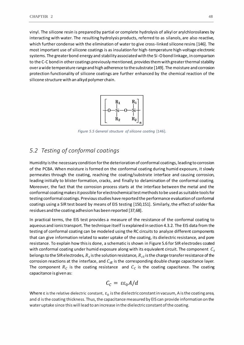
CHAPTER 2 48
vinyl. The silicone resin is prepared by partial or complete hydrolysis of alkyl or arylchlorosilanes by
interacting with water. The resulting hydrolysis products, referred to as silanols, are also reactive,
which further condense with the elimination of water to give cross-linked silicone resins [146]. The
most important use of silicone coatings is as insulation for high-temperature high-voltage electronic
systems. The greater bond energy and stability associated with the Si -O bond linkage, in comparison
to the C-C bond in other coatings previously mentioned, provides them with greater thermal stability
over a wide temperature range and high adherence to the substrate [149]. The moisture and corrosion
protection functionality of silicone coatings are further enhanced by the chemical reaction of the
silicone structure with an alkyd polymer chain.
Figure 5.5 General structure of silicone coating [146].
5.2 Testing of conformal coatings
Humidity is the necessary condition for the deterioration of conformal coatings, leading to corrosion
of the PCBA. When moisture is formed on the conformal coating during humid exposure, it slowly
permeates through the coating, reaching the coating/substrate interface and causing corrosion,
leading initially to blister formation, cracks, and finally to delamination of the conformal coating.
Moreover, the fact that the corrosion process starts at the interface between the metal and the
conformal coating makes it possible for electrochemical test methods to be used as suitable tools for
testing conformal coatings. Previous studies have reported the performance evaluation of conformal
coatings using a SIR test board by means of EIS testing [150,151]. Similarly, the effect of solder flux
residues and the coating adhesion has been reported [37,68].
In practical terms, the EIS test provides a measure of the resistance of the conformal coating to
aqueous and ionic transport. The technique itself is explained in section 4.3.2. The EIS data from the
testing of conformal coating can be modeled using the RC circuits to analyze different components
that can give information related to water uptake of the coating, its dielectric resistance, and pore
resistance. To explain how this is done, a schematic is shown in Figure 5.6 for SIR electrodes coated
with conformal coating under humid exposure along with its equivalent circuit. The component 𝐶𝑠
belongs to the SIR electrodes, 𝑅𝑠 is the solution resistance, 𝑅𝑐𝑡 is the charge transfer resistance of the
corrosion reactions at the interface, and 𝐶𝑑𝑙 is the corresponding double charge capacitance layer.
The component 𝑅𝐶 is the coating resistance and 𝐶𝐶 is the coating capacitance. The coating
capacitance is given as:
𝐶𝐶 = εε0𝐴/𝑑
Where ε is the relative dielectric constant, ε0 is the dielectric constant in vacuum, A is the coating area,
and d is the coating thickness. Thus, the capacitance measured by EIS can provide information on the
water uptake since this will lead to an increase in the dielectric constant of the coating.
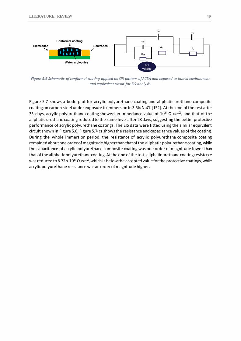
LITERATURE REVIEW 49
Figure 5.6 Schematic of conformal coating applied on SIR pattern of PCBA and exposed to humid environment
and equivalent circuit for EIS analysis.
Figure 5.7 shows a bode plot for acrylic polyurethane coating and aliphatic urethane composite
coating on carbon steel under exposure to immersion in 3.5% NaCl [152]. At the end of the test after
35 days, acrylic polyurethane coating showed an impedance value of 106 Ω 𝑐𝑚2, and that of the
aliphatic urethane coating reduced to the same level after 28 days, suggesting the better protective
performance of acrylic polyurethane coatings. The EIS data were fitted using the similar equivalent
circuit shown in Figure 5.6. Figure 5.7(c) shows the resistance and capacitance values of the coating.
During the whole immersion period, the resistance of acrylic polyurethane composite coating
remained about one order of magnitude higher than that of the aliphatic polyurethane coating, while
the capacitance of acrylic polyurethane composite coating was one order of magnitude lower than
that of the aliphatic polyurethane coating. At the end of the test, aliphatic urethane coating resistance
was reduced to 8.72 x 10⁶ Ω 𝑐𝑚2, which is below the accepted value for the protective coatings, while
acrylic polyurethane resistance was an order of magnitude higher.
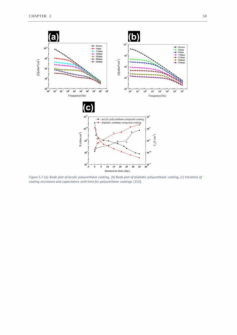
CHAPTER 2 50
Figure 5.7 (a): Bode plot of acrylic polyurethane coating, (b) Bode plot of aliphatic polyurethane coating, (c) Variation of
coating resistance and capacitance with time for polyurethane coatings [152].
LITERATURE REVIEW 51
6 Overview of literature and current work
The corrosion reliability of electronic devices is affected by the formation of water layer on their
surfaces under biased conditions. The formation of water on the electronic surfaces is affected by
number of factors such as climatic conditions, surface properties of components, and various kinds of
contamination as discussed in section 2 of the literature review. Similarly, hearing aid devices, due to
their small size, multi material combinations and harsh user conditions, are equally prone to moisture
related corrosion failures. The various humidity and contamination induced failures discussed in
section 3 can occur in hearing aid devices during field operation and are expected to be severe due to
its long duration of exposure to climatic conditions as well as in contact with the human body.
To address these moisture-induced failures and develop a better climatically reliable hearing aid
device will require indepth knowledge of its failure modes and mechanisms to reveal the criticality
and severity of the operational and environmental stresses. This can be achieved by following a
scientific approach (PoF) for conducting root cause failure analysis to address field failures and list all
potential failure modes, mechanisms and causes for field failed hearing aid devices as discussed in
section 4. Even though various studies has been done in the past to understand the effect of
atmospheric pollutants, humidity, process related residues on the corrosion reliability of electronics,
none of them specifically focus on hearing aids. The aim of the studies presented in chapters 3 and 4
was to understand the mechanism of field generated failures in hearing aids from different markets
and identify the failure causes, which can be used for better product design, corrosion protection
strategy, and development of corrosion test methods.
Literature in section 2 discusses about the types of contamination and their sources responsible for
affecting the reliability of electronics, while section 4 presents various electrical testing available for
investigating the impact of contamination on electrical failures using standard test PCBA boards. The
focus of the current investigation in Chapter 5 was placed on understanding the hygroscopic behavior
of KOH (Potassium hydroxide) residues and its impact on the corrosion reliability of electronics using
EIS and water sorption and desorption techniques. This study is directly motivated from the learning
of chapters 3 and 4, where leakage of KOH electrolyte from hearing aid batteries (Zn-air) was the
prominent failure cause, particularly in tropical regions. Different hearing aid battery types were
characterized based on their ability to cause battery leakage under varying climatic test conditions
(humidity and temperature effect), as a part of the investigation in chapter 5.
The device level testing of hearing aids is important for assessing the product reliability and are often
performed under accelerating conditions for quick assessment of failures. These acceleration factors
are related to the field environmental conditions and its associated stressors. Well, it is easy to find
the climatic conditions of the field, but the knowledge about the corrosive contamination and its
nature can only be derived from the root cause failure analysis study conducted in chapters 3 and 4.
Various standard methods for device level testing were presented in the literature for testing the
synergetic effect of climatic conditions and contamination on the corrosion reliability of electronics
using testing chambers for simulating the field conditions. Motivated from the literature, the study
shown in chapter 6 focuses on the development of accelerated corrosion test methods for replicating
field failures and address the individual impact of corrosion causing factors towards hearing aid failure
and its overall reliability.
Finally, the reliability of hearing aid devices will depend on the type of corrosion prote ction strategy
employed for its protection from external climatic conditions and contaminations. The literature
shown in section 5 discusses extensively on the corrosion protection of electronics using conformal
CHAPTER 2 52
coating and their different types. However, the performance of conformal coatings depends on its
surface adhesion and water transport properties, which needs to be evaluated for finding the
appropriate type for hearing aid application. Testing of conformal coatings using impedance
spectroscopy (EIS) and electrical equivalent circuit to find coating performance parameters is
explained thoroughly in the literature. Using EIS along with DC leak current testing, the performance
of different types of conformal coatings were evaluated under cyclic climatic and field exposure
conditions in chapter 7. The testing was carried out using a special ly designed test board that
represents a hearing aid circuitry and the best performing coating candidate will be chosen as a
hearing aid corrosion protection method.
LITERATURE REVIEW 53
References
[1] S. Joshy, V. Verdingovas, M.S. Jellesen, R. Ambat, Circuit analysis to predict humidity related failures in electronics - Methodology and recommendations, Microelectron. Reliab. 93 (2019). https://doi.org/10.1016/j.microrel.2018.12.010.
[2] R. Ambat, H. Conseil-Gudla, V. Verdingovas, Corrosion in electronics, in: Encycl. Interfacial Chem. Surf. Sci. Electrochem., 2018. https://doi.org/10.1016/B978-0-12-409547-2.13437-7.
[3] R. Hienonen, R. Lahtinen, Corrosion and climatic effects in electronics, VTT Publ. (2007).
[4] E.H. Wong, S.W. Koh, K.H. Lee, R. Rajoo, Comprehensive treatment of moisture induced failure - Recent advances, IEEE Trans. Electron. Packag. Manuf. 25 (2002) 223–230. https://doi.org/10.1109/TEPM.2002.804613.
[5] H. Conseil, M.S. Jellesen, V. Verdingovas, R. Ambat, Decomposition studies of no-clean solder flux systems in connection with corrosion reliability of electronics, Eurocorr 2013. (2013).
[6] V. Verdingovas, M.S. Jellesen, R. Ambat, Impact of NaCl contamination and climatic conditions on the reliability of printed circuit board assemblies, IEEE Trans. Device Mater. Reliab. 14 (2014). https://doi.org/10.1109/TDMR.2013.2293792.
[7] V. Verdingovas, M.S. Jellesen, R. Ambat, Effect of ionic contamination on climatic reliability of printed circuit board assemblies, in: Proc. Eur. Corros. Congr. 2012, 2012.
[8] V. Verdingovas, M.S. Jellesen, R. Ambat, Relative effect of solder flux chemistry on the humidity related failures in electronics, Solder. Surf. Mt. Technol. (2015). https://doi.org/10.1108/SSMT-11-2014-0022.
[9] M.S. Jellesen, D. Minzari, U. Rathinavelu, P. Møller, R. Ambat, Corrosion failure due to flux residues in an electronic add-on device, Eng. Fail. Anal. (2010). https://doi.org/10.1016/j.engfailanal.2010.02.010.
[10] H. Conseil-Gudla, Parametric study of interior climate in electronic device enclosures and corrosion reliability, 2017.
[11] M.G. Lawrence, The relationship between relative humidity and the dewpoint temperature in moist air: A simple conversion and applications, Bull. Am. Meteorol. Soc. 86 (2005). https://doi.org/10.1175/BAMS-86-2-225.
[12] S. Saran, M. Gurjar, A. Baronia, V. Sivapurapu, P.S. Ghosh, G.M. Raju, I. Maurya, Heating, ventilation and air conditioning (HVAC) in intensive care unit, Crit. Care. 24 (2020). https://doi.org/10.1186/s13054-020-02907-5.
[13] L.J. Mauer, L.S. Taylor, Water-solids interactions: Deliquescence, Annu. Rev. Food Sci. Technol. 1 (2010). https://doi.org/10.1146/annurev.food.080708.100915.
[14] M. Tencer, Moisture ingress into nonhermetic enclosures and packages. A quasi -steady state model for diffusion and attenuation of ambient humidity variations, in: Proc. - Electron. Components Technol. Conf., 1994. https://doi.org/10.1109/ectc.1994.367630.
[15] A. Roman, B. Wu, B. Han, G.M. Reinacher, S.G. Yousef, Moisture Transport through Housing Materials Enclosing Critical Automotive Electronics, IEEE Trans. Components, Packag. Manuf. Technol. 10 (2020). https://doi.org/10.1109/TCPMT.2020.2977111.
[16] N. Dahan, A. Vanhoestenberghe, N. Donaldson, Moisture ingress into packages with walls of varying thickness and/or properties: A simple calculation method, IEEE Trans. Components,
CHAPTER 2 54
Packag. Manuf. Technol. 2 (2012). https://doi.org/10.1109/TCPMT.2012.2210425.
[17] Staliulionis, H. Conseil-Gudla, S. Mohanty, M. Jabbari, R. Ambat, J.H. Hattel, Modeling of Moisture Transport into an Electronic Enclosure Using the Resistor-Capacitor Approach, J. Electron. Packag. Trans. ASME. 140 (2018). https://doi.org/10.1115/1.4039790.
[18] P.S. Nasirabadi, H. Conseil-Gudla, S. Mohanty, M. Jabbari, R. Ambat, J.H. Hattel, Semi-empirical prediction of moisture build-up in an electronic enclosure using analysis of variance (ANOVA), in: Proc. 2016 IEEE 18th Electron. Packag. Technol. Conf. EPTC 2016, 2017. https://doi.org/10.1109/EPTC.2016.7861588.
[19] O.D. Neikov, N.A. Yefimov, Powder Characterization and Testing, in: Handb. Non-Ferrous Met. Powders, 2019. https://doi.org/10.1016/b978-0-08-100543-9.00001-4.
[20] C.E. Hoge, Corrosion Criteria for Electronic Packaging: Part I—A Framework for Corrosion of Integrated Circuits, IEEE Trans. Components, Hybrids, Manuf. Technol. 13 (1990). https://doi.org/10.1109/33.62553.
[21] B. Da Yan, S.L. Meilink, G.W. Warren, P. Wynblatt, Water Adsorption and Surface Conductivity Measurements on α-Alumina Substrates, IEEE Trans. Components, Hybrids, Manuf. Technol. 10 (1987). https://doi.org/10.1109/TCHMT.1987.1134727.
[22] P. Shojaee Nasirabadi, M. Jabbari, J.H. Hattel, CFD simulation and statistical analysis of moisture transfer into an electronic enclosure, Appl. Math. Model. 44 (2017). https://doi.org/10.1016/j.apm.2016.09.004.
[23] K. Piotrowska, R.U. Din, M.S. Jellesen, R. Ambat, Effect of solder mask surface chemistry and morphology on the water layer formation under humid conditions, IEEE Trans. Components, Packag. Manuf. Technol. 8 (2018). https://doi.org/10.1109/TCPMT.2018.2792047.
[24] M. Tencer, J.S. Moss, Humidity management of outdoor electronic equipment: Methods, pitfalls, and recommendations, IEEE Trans. Components Packag. Technol. 25 (2002) 66–72. https://doi.org/10.1109/6144.991177.
[25] Vadimas Verdingovas, Climatic Reliability of Electronics: Early Prediction and Control of Contamination and humidity effects, Technical University of Dnemark, 2015. https://orbit.dtu.dk/en/publications/climatic-reliability-of-electronics-early-prediction-and-control-.
[26] W. Gao, Z. Li, Nanostructured transition metal oxides and their applications in composites, in: Phys. Prop. Appl. Polym. Nanocomposites, 2010. https://doi.org/10.1533/9780857090249.4.723.
[27] R.S. Hebbar, A.M. Isloor, A.F. Ismail, Contact Angle Measurements, in: Membr. Charact., 2017. https://doi.org/10.1016/B978-0-444-63776-5.00012-7.
[28] M. Pecht, E.M. Bumiller, D.A. Douthit, J. Pecht, Contamination of electronic assemblies, 2002. https://doi.org/10.1201/9781420040067.
[29] C. Schimpf, K. Feldmann, C. Matzner, A. Steinke, Failure of electronic devices due to condensation, in: Microsyst. Technol., 2009. https://doi.org/10.1007/s00542-008-0643-y.
[30] D. Minzari, Investigation of Electronic Corrosion Mechanisms, Technical University of Denmark, 2010. https://backend.orbit.dtu.dk/ws/portalfiles/portal/5205309/D.+Minzari+-Thesis+Final+for+print.pdf.
[31] V. Verdingovas, M.S. Jellesen, R. Ambat, Solder Flux Residues and Humidity-Related Failures in Electronics: Relative Effects of Weak Organic Acids Used in No-Clean Flux Systems, J. Electron.
LITERATURE REVIEW 55
Mater. 44 (2015). https://doi.org/10.1007/s11664-014-3609-0.
[32] V. Verdingovas, M.S. Jellesen, R. Ambat, Relative effect of solder flux chemistry on the humidity related failures in electronics, Solder. Surf. Mt. Technol. 27 (2015) 146–156. https://doi.org/10.1108/SSMT-11-2014-0022.
[33] K. Piotrowska, V. Verdingovas, M.S. Jellesen, R. Ambat, Contamination , potential bias and humidity effects on electrical performance and corrosion reliability of electronic devices, Proc. Eur. Corros. Congr. (2015).
[34] H. Conseil, V. Verdingovas, M.S. Jellesen, R. Ambat, Decomposition of no-clean solder flux systems and their effects on the corrosion reliability of electronics, J. Mater. Sci. Mater. Electron. (2016). https://doi.org/10.1007/s10854-015-3712-x.
[35] J.H. Lau, P.A. Engel, Solder Joint Reliability—Theory and Applications, J. Electron. Packag. 114 (1992). https://doi.org/10.1115/1.2905434.
[36] M. Nasta, H.C. Peebles, H.C. Peebles, A Model of the Solder Flux Reaction; Reactions at the Metal/ Metal Oxide/Electrolyte Solution Interface, Circuit World. 21 (1995). https://doi.org/10.1108/eb044043.
[37] U. Rathinavelu, M.S. Jellesen, P. Moller, R. Ambat, Effect of no-clean flux residues on the performance of acrylic conformal coating in aggressive environments, IEEE Trans. Components, Packag. Manuf. Technol. 2 (2012). https://doi.org/10.1109/TCPMT.2012.2186456.
[38] H. Conseil, M.S. Jellesen, R. Ambat, Contamination profile on typical printed circuit board assemblies vs soldering process, Solder. Surf. Mt. Technol. (2014). https://doi.org/10.1108/SSMT-03-2014-0007.
[39] R. Ambat, Perspectives on climatic reliability of electronic devices and components, in: IMAPS Nord. Annu. Conf. Proc. 2012, 2012.
[40] K. Piotrowska, R. Ud Din, F.B. Grumsen, M.S. Jellesen, R. Ambat, Parametric Study of Solder Flux Hygroscopicity: Impact of Weak Organic Acids on Water Layer Formation and Corrosion of Electronics, J. Electron. Mater. 47 (2018). https://doi.org/10.1007/s11664-018-6311-9.
[41] M. Ohring, Environmental Damage to Electronic Products, in: Reliab. Fail. Electron. Mater. Devices, 1998. https://doi.org/10.1016/b978-012524985-0/50008-8.
[42] M. Reid, J. Punch, B. Rodgers, M.J. Pomeroy, T. Galkin, T. Stenberg, O. Rusanen, E. Elonen, M. Vilèn, K. Väkeväinen, Factors that influence ionic migration on printed wiring boards, in: IEEE Int. Reliab. Phys. Symp. Proc., 2005. https://doi.org/10.1109/relphy.2005.1493102.
[43] Department of Defense, Standard Requirements for Soldered Electrical and Electronic Assemblies, Distribution. 1313 (1994).
[44] IPC J-STD-001E released: Industry Requirements for Soldered Electrical and Electronic Assemblies Updated, Solder. Surf. Mt. Technol. 22 (2010). https://doi.org/10.1108/ssmt.2010.21922cab.006.
[45] V.C. Gudla, R. Ambat, Corrosion failure analysis of hearing aid battery-spring contacts, Eng. Fail. Anal. (2017). https://doi.org/10.1016/j.engfailanal.2017.05.045.
[46] R.B. Comizzoli, R.P. Frankenthal, P.C. Milner, J.D. Sinclair, Corrosion of electronic materials and devices, Science (80-. ). (1986). https://doi.org/10.1126/science.234.4774.340.
[47] F.S. Pérez, A.O. Prado, Environmental Effects on Electronic Devices in Mexico, Mater. Sci. Appl. 10 (2019). https://doi.org/10.4236/msa.2019.103020.
CHAPTER 2 56
[48] M. Chin, T. Diehl, P. Ginoux, W. Malm, Intercontinental transport of pollution and dust aerosols: Implications for regional air quality, Atmos. Chem. Phys. 7 (2007). https://doi.org/10.5194/acp-7-5501-2007.
[49] NASA, New Map Offers a Global View of Health-Sapping Air Pollution, NASA. (2010).
[50] Y.N. Liang, J.G. Zhang, J.J. Liu, Identification of inorganic compounds of dust and their effects on electric contact failure, in: Electr. Contacts, Proc. Annu. Holm Conf. Electr. Contacts, 1997. https://doi.org/10.1109/holm.1997.638057.
[51] X.Y. Lin, J.G. Zhang, Dust corrosion, in: Proc. 50th IEEE Holm Conf. Electr. Contacts 22nd Int. Conf. Electr. Contacts, 2004. https://doi.org/10.1109/holm.2004.1353127.
[52] M.S. Jellesen, V. Verdingovas, S. Davidsdottir, R. Ambat, Sulphur induced corrosion of electronics, in: Eur. Corros. Congr. EUROCORR 2015, 2015.
[53] O.L. Vargas, S.B. Valdez, M.L. Veleva, K.R. Zlatev, W.M. Schorr, G.J. Terrazas, The corrosion of silver in indoor conditions of an assembly process in the microelectronics industry, Anti-Corrosion Methods Mater. 56 (2009). https://doi.org/10.1108/00035590910969347.
[54] Y. Zhou, Y. Li, Y. Chen, Insulation Failure Mechanism of Immersion Silver Finished Printed Circuit Board Under NaCl Solution, J. Electron. Mater. 49 (2020). https://doi.org/10.1007/s11664-019-07885-1.
[55] H. Conseil-Gudla, M.S. Jellesen, R. Ambat, Printed Circuit Board Surface Finish and Effects of Chloride Contamination, Electric Field, and Humidity on Corrosion Reliability, J. Electron. Mater. 46 (2017). https://doi.org/10.1007/s11664-016-4974-7.
[56] A.B. Stefaniak, C.J. Harvey, Dissolution of materials in artificial skin surface film liquids, Toxicol. Vitr. 20 (2006). https://doi.org/10.1016/j.tiv.2006.05.011.
[57] A.K. Salameh, L.S. Taylor, Deliquescence in binary mixtures, Pharm. Res. 22 (2005). https://doi.org/10.1007/s11095-005-1563-5.
[58] L. van Campen, G.L. Amidon, G. Zografi, Moisture sorption kinetics for water‐soluble substances I: Theoretical considerations of heat transport control, J. Pharm. Sci. 72 (1983). https://doi.org/10.1002/jps.2600721204.
[59] M.C. Foster, G.E. Ewing, Adsorption of water on the NaCl(001) surface. II. An infrared study at ambient temperatures, J. Chem. Phys. 112 (2000). https://doi.org/10.1063/1.481256.
[60] G. Zografi, States of water associated with solids, Drug Dev. Ind. Pharm. 14 (1988). https://doi.org/10.3109/03639048809151997.
[61] K.M. Adams, J.E. Anderson, Y.B. Graves, Ionograph Sensitivity to Chemical Residues From ‘no Clean Soldering Fluxes: Comparison Of Solvent Extract Conductivity and Surface Conductivity, Circuit World. 20 (1994). https://doi.org/10.1108/eb046251.
[62] C. Peng, M.N. Chan, C.K. Chan, The hygroscopic properties of dicarboxylic and multifunctional acids: Measurements and UNIFAC predictions, Environ. Sci. Technol. 35 (2001). https://doi.org/10.1021/es0107531.
[63] P. Saxena, L.M. Hildemann, Water absorption by organics: Survey of laboratory/evidence and evaluation of UNIFAC for estimating water activity, Environ. Sci. Technol. 31 (1997). https://doi.org/10.1021/es9703638.
[64] C.N. Cruz, S.N. Pandis, Deliquescence and hygroscopic growth of mixed inorganic - Organic atmospheric aerosol, Environ. Sci. Technol. 34 (2000). https://doi.org/10.1021/es9907109.
LITERATURE REVIEW 57
[65] A. Apelblat, M. Dov, J. Wisniak, J. Zabicky, The vapour pressure of water over saturated aqueous solutions of malic, tartaric, and citric acids, at temperatures from 288 K to 323 K, J. Chem. Thermodyn. 27 (1995). https://doi.org/10.1006/jcht.1995.0004.
[66] N.C. Man, S.M. Kreidenweis, C.K. Chan, Measurements of the hygroscopic and deliquescence properties of organic compounds of different solubilities in water and their relationship with cloud condensation nuclei activities, Environ. Sci. Technol. 42 (2008). https://doi.org/10.1021/es7023252.
[67] P.-E. Tegehall, Impact of Humidity and Contamination on Surface Insulation Resistance and Electrochemical Migration, in: ELFNET B. Fail. Mech. Test. Methods, Qual. Issues Lead-Free Solder Interconnects, 2011. https://doi.org/10.1007/978-0-85729-236-0_10.
[68] U. Rathinavelu, Developing Strategies for Corrosion Protection of Electronic Devices, Technical University of Denmark, 2011. https://orbit.dtu.dk/en/projects/developing-strategies-for-corrosion-protection-of-electronic-devi.
[69] W. Lawson, The Effects of Design and Environmental Factors on the Reliability of Electronic Products, University of Salford, UK, 2007. http://usir.salford.ac.uk/id/eprint/2033/1/Wayne_Lawson_PhD_Thesis_-_THE_EFFECTS_OF_DESIGN_AND_ENVIRONMENTAL_FACTORS_ON_THE_RELIABILITY_OF_ELECTRONIC_PRODUCTS.pdf.
[70] X. Zhong, G. Zhang, X. Guo, The effect of electrolyte layer thickness on electrochemical migration of tin, Corros. Sci. 96 (2015). https://doi.org/10.1016/j.corsci.2015.04.014.
[71] D. Minzari, M.S. Jellesen, P. Moller, P. Wahlberg, R. Ambat, Electrochemical migration on electronic chip resistors in chloride environments, IEEE Trans. Device Mater. Reliab. 9 (2009) 392–402. https://doi.org/10.1109/TDMR.2009.2022631.
[72] K. Piotrowska, V. Verdingovas, M.S. Jellesen, R. Ambat, Contamination, potential bias and humidity effects on electrical performance and corrosion reliability of electronic devices, in: Eur. Corros. Congr. EUROCORR 2015, 2015.
[73] D. Minzari, M.S. Jellesen, P. Møller, R. Ambat, On the electrochemical migration mechanism of tin in electronics, Corros. Sci. (2011). https://doi.org/10.1016/j.corsci.2011.06.015.
[74] Y.R. Yoo, Y.S. Kim, Influence of electrochemical properties on electrochemical migration of SnPb and SnBi solders, Met. Mater. Int. 16 (2010). https://doi.org/10.1007/s12540-010-1007-6.
[75] L. Zou, C. Hunt, Surface insulation resistance (SIR) response to various processing parameters, Solder. Surf. Mt. Technol. 11 (1999). https://doi.org/10.1108/09540919910265668.
[76] G.W. Warren, P. Wynblatt, M. Zamanzadeh, The role of electrochemical migration and moisture adsorption on the reliability of metallized ceramic substrates, J. Electron. Mater. 18 (1989). https://doi.org/10.1007/BF02657426.
[77] X. Zhong, L. Chen, B. Medgyes, Z. Zhang, S. Gao, L. Jakab, Electrochemical migration of Sn and Sn solder alloys: A review, RSC Adv. 7 (2017). https://doi.org/10.1039/c7ra04368f.
[78] J. Dryzek, Migration of vacancies in deformed silver studied by positron annihilation, Mater. Sci. Forum. 255–257 (1997). https://doi.org/10.4028/www.scientific.net/msf.255-257.533.
[79] R.C. Benson, B.M. Romenesko, J.A. Weiner, B.H. Nall, H.K. Charles, Metal Electromigration Induced by Solder Flux Residue in Hybrid Microcircuits, IEEE Trans. Components, Hybrids, Manuf. Technol. 11 (1988). https://doi.org/10.1109/33.16669.

CHAPTER 2 58
[80] P. Viswanadham, P. Singh, Failure Modes and Mechanisms in Electronic Packages, 1998. https://doi.org/10.1007/978-1-4615-6029-6.
[81] A. Caputo, L.J. Turbini, D.D. Perovic, Conductive anodic filament (CAF) formation part I: The influence of water-soluble flux on its formation, J. Electron. Mater. 39 (2010). https://doi.org/10.1007/s11664-009-0964-3.
[82] A. Caputo, L.J. Turbini, D.D. Perovic, Characterization and electrochemical mechanism for bromide-containing conductive anodic filament (CAF) failure, J. Electron. Mater. 40 (2011). https://doi.org/10.1007/s11664-011-1694-x.
[83] W.J. Ready, L.J. Turbini, The effect of flux chemistry, applied voltage, conductor spacing, and temperature on conductive anodic filament formation, J. Electron. Mater. 31 (2002). https://doi.org/10.1007/s11664-002-0012-z.
[84] R. Ambat, P. Møller, Corrosion investigation of material combinations in a mobile phone dome-key pad system, Corros. Sci. (2007). https://doi.org/10.1016/j.corsci.2006.12.013.
[85] J.W. Osenbach, Corrosion-induced degradation of microelectronic devices, Semicond. Sci. Technol. 11 (1996). https://doi.org/10.1088/0268-1242/11/2/002.
[86] Galvanic Aluminum Bond Pad Corrosion in Copper Wire Bonded Device Assembly – Mechanism and Prevention, ECS Meet. Abstr. (2019). https://doi.org/10.1149/ma2019-01/16/977.
[87] E. Salahinejad, R. Eslami Farsani, L. Tayebi, Synergistic galvanic-pitting corrosion of copper electrical pads treated with electroless nickel-phosphorus/immersion gold surface finish, Eng. Fail. Anal. (2017). https://doi.org/10.1016/j.engfailanal.2017.03.001.
[88] V.C. Gudla, R. Ambat, Corrosion failure analysis of hearing aid battery-spring contacts, Eng. Fail. Anal. 79 (2017) 980–987. https://doi.org/10.1016/j.engfailanal.2017.05.045.
[89] E.F. Monlevade, I.A.P. Cardoso, E.F.L. Maciel, N. Alonso-Falleiros, Galvanic corrosion of electroless nickel/immersion gold plated non-permanent electric contacts used in electronic devices–direct evidence of triggering mechanism, Eng. Fail. Anal. 96 (2019). https://doi.org/10.1016/j.engfailanal.2018.12.001.
[90] T.K. Lee, C.D. Breach, W.L. Chong, C.S. Goh, Oxidation and corrosion of Au/Al and Cu/Al in wire bonding assembly, in: ICEPT-HDP 2012 Proc. - 2012 13th Int. Conf. Electron. Packag. Technol. High Density Packag., 2012. https://doi.org/10.1109/ICEPT-HDP.2012.6474610.
[91] O. Chyan, N. Ross, M. Asokan, A. Lambert, S. Berhe, M. Chowdhury, S.O. Connor, L. Nguyen, Mechanistic Investigation and Prevention of Al Bond Pad Corrosion in Cu Wire -Bonded Device Assembly, in: Proc. - Electron. Components Technol. Conf., 2017. https://doi.org/10.1109/ECTC.2017.43.
[92] T. Uno, S. Terashima, T. Yamada, Surface-enhanced copper bonding wire for LSI, in: Proc. - Electron. Components Technol. Conf., 2009. https://doi.org/10.1109/ECTC.2009.5074209.
[93] T. Uno, T. Yamada, Improving humidity bond reliability of copper bonding wires, in: Proc. - Electron. Components Technol. Conf., 2010. https://doi.org/10.1109/ECTC.2010.5490741.
[94] M. White, J.B. Bernstein, Microelectronics reliability: physics-of-failure based modeling and lifetime evaluation, JPL Publ. (2008). https://doi.org/http://hdl.handle.net/2014/40791.
[95] Physics of Failure Reliability Predictions, VMEbus International Trade Association, Standard ANSI/VITA 51.2, 2011.
[96] J. Cui, Y. Ren, D. Yang, S. Zeng, Model based FMEA for electronic products, in: 2015 First Int.
LITERATURE REVIEW 59
Conf. Reliab. Syst. Eng., IEEE, 2015: pp. 1–6. https://doi.org/10.1109/ICRSE.2015.7366461.
[97] S. Mathew, D. Das, R. Rossenberger, M. Pecht, Failure mechanisms based prognostics, in: 2008 Int. Conf. Progn. Heal. Manag. PHM 2008, 2008. https://doi.org/10.1109/PHM.2008.4711438.
[98] M. White, Microelectronics reliability: physics-of-failure based modeling and lifetime evaluation, JPL Publ. (2008) 1–216. https://doi.org/http://hdl.handle.net/2014/40791.
[99] Z. Matic, V. Sruk, The Physics-of-Failure approach in reliability engineering, in: Proc. Int. Conf. Inf. Technol. Interfaces, ITI, 2008: pp. 745–750. https://doi.org/10.1109/ITI.2008.4588504.
[100] J.G. McLeish, Transitioning to physics of failure reliability assessments for electronics, in: Proc. - 16th ISSAT Int. Conf. Reliab. Qual. Des., 2010.
[101] A.B. Temsamani, S. Kauffmann, Y. Descas, B. Vandevelde, F. Zanon, G. Willems, Improved and accurate physics-of-failure (PoF) methodology for qualification and lifetime assessment of electronic systems, Microelectron. Reliab. 76–77 (2017). https://doi.org/10.1016/j.microrel.2017.06.047.
[102] S. Mathew, M. Alam, M. Pecht, Identification of failure mechanisms to enhance prognostic outcomes, J. Fail. Anal. Prev. (2012). https://doi.org/10.1007/s11668-011-9508-2.
[103] J. Romero, M.H. Azarian, C. Morillo, M. Pecht, Effects of Moisture and Temperature on Membrane Switches in Laptop Keyboards, IEEE Trans. Device Mater. Reliab. 18 (2018) 535–545. https://doi.org/10.1109/TDMR.2018.2866776.
[104] L.L. Tessa, B.P. Sood, M.G. Pecht, Field reliability estimation for cochlear implants, IEEE Trans. Biomed. Eng. 62 (2015). https://doi.org/10.1109/TBME.2015.2412127.
[105] G. Yang, Life Cycle Reliability Engineering, in: Life Cycle Reliab. Eng., 2007: pp. 1–517. https://doi.org/10.1002/9780470117880.ch7.
[106] P.D.T. O’Connor, A. Kleyner, Practical Reliability Engineering: Fifth Edition, 2011. https://doi.org/10.1002/9781119961260.
[107] J.J. Shea, Electronic failure analysis handbook: techniques and applications for electronic and electrical packages, components, and assemblies [Book Reviews], IEEE Electr. Insul. Mag. 16 (2005). https://doi.org/10.1109/mei.2000.817421.
[108] Reliability and Failure of Electronic Materials and Devices, 2016. https://doi.org/10.1016/b978-0-12-524985-0.x5000-4.
[109] J.D. Rancourt, J. Brooks, S. Mecham, A. Sentman, B. Starr, J. Todd, Chapter 15 Failure, Defect, and Contaminant Analysis, Compr. Anal. Chem. 53 (2008). https://doi.org/10.1016/S0166-526X(08)00415-7.
[110] P.R. Thornton, D. V. Sulway, D.A. Shaw, Scanning Electron Microscopy in Device Diagnostics and Reliability Physics, IEEE Trans. Electron Devices. 16 (1969). https://doi.org/10.1109/T-ED.1969.16758.
[111] S. Brand, K. Raum, P. Czuratis, P. Hoffrogge, Signal analysis in scanning acoustic microscopy for non-destructive assessment of connective defects in flip-chip BGA devices, in: Proc. - IEEE Ultrason. Symp., 2007. https://doi.org/10.1109/ULTSYM.2007.209.
[112] Y. Ousten, S. Mejdi, A. Fenech, J.Y. Deletage, L. Bechou, M.G. Perichaud, Y. Danto, The use of impedance spectroscopy, SEM and SAM imaging for early detection of failure in SMT assemblies, Microelectron. Reliab. 38 (1998). https://doi.org/10.1016/S0026-2714(98)00060-2.
CHAPTER 2 60
[113] M. Reid, J. Punch, C. Ryan, J. Franey, G.E. Derkits, W.D. Reents, L.F. Garfias, The corrosion of electronic resistors, IEEE Trans. Components Packag. Technol. 30 (2007). https://doi.org/10.1109/TCAPT.2007.901749.
[114] C.A. Smith, Failure analysis of electronic components and interconnection systems, Circuit World. 33 (2007). https://doi.org/10.1108/03056120710723670.
[115] J.I. Goldstein, D.E. Newbury, J.R. Michael, N.W.M. Ritchie, J.H.J. Scott, D.C. Joy, Scanning electron microscopy and x-ray microanalysis, 2017. https://doi.org/10.1007/978-1-4939-6676-9.
[116] G. Zhai, B. Zheng, X. Ye, S. Si, E. Zio, A failure mechanism consistency test method for accelerated degradation test, Qual. Reliab. Eng. Int. 37 (2021). https://doi.org/10.1002/qre.2744.
[117] C.M. Tan, P. Singh, Time evolution degradation physics in high power white LEDs under high temperature-humidity conditions, IEEE Trans. Device Mater. Reliab. 14 (2014). https://doi.org/10.1109/TDMR.2014.2318725.
[118] M. Patel, A.R. Skinner, Thermal ageing studies on room-temperature vulcanised polysiloxane rubbers, Polym. Degrad. Stab. 73 (2001). https://doi.org/10.1016/S0141-3910(01)00118-5.
[119] B. Sood, M. Pecht, Conductive filament formation in printed circuit boards: Effects of reflow conditions and flame retardants, J. Mater. Sci. Mater. Electron. 22 (2011). https://doi.org/10.1007/s10854-011-0449-z.
[120] R. Jellesen, Morten Stendahl; Minzari, Daniel; Rathinavelu, Umadevi; Møller, Per; Ambat, Investigation of Electronic Corrosion at Device Level, E C S Trans. 25 (2010) 1–14. https://doi.org/10.1149/1.3321952.
[121] G.K. Morris, C. Genthe, R.A. Lukaszewski, Challenges and best practices in mixed flow gas corrosion testing of electronics, in: Proc. - Annu. Reliab. Maintainab. Symp., 2019. https://doi.org/10.1109/RAMS.2019.8768973.
[122] ASTM, ASTM G85-11: Standard Practice for Modified Salt Spray (Fog) Testing, ASTM Stand. i (2011).
[123] P. Eriksson, B. Carlsson, I.O. Wallinder, Design of accelerated corrosion tests for electronic components in automotive applications, IEEE Trans. Components Packag. Technol. 24 (2001). https://doi.org/10.1109/6144.910808.
[124] N. Lebozec, N. Blandin, D. Thierry, Accelerated corrosion tests in the automotive industry: A comparison of the performance towards cosmetic corrosion, Mater. Corros. 59 (2008). https://doi.org/10.1002/maco.200804168.
[125] S. Zhan, M.H. Azarian, M.G. Pecht, Surface insulation resistance of conformally coated printed circuit boards processed with no-clean flux, IEEE Trans. Electron. Packag. Manuf. 29 (2006). https://doi.org/10.1109/TEPM.2006.882496.
[126] D. Pauls, Test vehicles in surface insulation resistance testing, Circuit World. 23 (1997). https://doi.org/10.1108/03056129710370213.
[127] S. Lauser, Implementation of Electrochemical Impedance Spectroscopy (EIS) for validation of humidity robustness of PCBA design elements, 2020. https://orbit.dtu.dk/en/publications/implementation-of-electrochemical-impedance-spectroscopy-eis-for--2.
[128] B.N. Ellis, On Insulation Resistance, Circuit World. 21 (1995) 5–18.

LITERATURE REVIEW 61
https://doi.org/https://doi.org/10.1108/eb046297.
[129] R. Srinivasan, F. Fasmin, An Introduction to Electrochemical Impedance Spectroscopy, 2021. https://doi.org/10.1201/9781003127932.
[130] J.R. Macdonald, Impedance spectroscopy and its use in analyzing the steady-state AC response of solid and liquid electrolytes, J. Electroanal. Chem. 223 (1987). https://doi.org/10.1016/0022-0728(87)85249-X.
[131] A. Lasia, Electrochemical impedance spectroscopy and its applications, 2014. https://doi.org/10.1007/978-1-4614-8933-7.
[132] L.C. Zou, C. Hunt, Characterization of the Conduction Mechanisms in Adsorbed Electrolyte Layers on Electronic Boards Using AC Impedance, J. Electrochem. Soc. 156 (2009). https://doi.org/10.1149/1.3005563.
[133] K. Fu, C. Lu, Y. Liu, H. Zhang, B. Zhang, H. Zhang, F. Zhou, Q. Zhang, B. Zhu, Mechanically robust, self-healing superhydrophobic anti-icing coatings based on a novel fluorinated polyurethane synthesized by a two-step thiol click reaction, Chem. Eng. J. 404 (2021). https://doi.org/10.1016/j.cej.2020.127110.
[134] F. Lu, B. Song, P. He, Z. Wang, J. Wang, Electrochemical impedance spectroscopy (EIS) study on the degradation of acrylic polyurethane coatings, RSC Adv. 7 (2017). https://doi.org/10.1039/c6ra26341k.
[135] M.C. Liew, I. Ahmad, L.M. Lee, M.F.M. Nazeri, H. Haliman, A.A. Mohamad, Corrosion behavior of Sn-3.0Ag-0.5Cu lead-free solder in potassium hydroxide electrolyte, Metall. Mater. Trans. A Phys. Metall. Mater. Sci. (2012). https://doi.org/10.1007/s11661-012-1194-5.
[136] M. Fayeka, A.S.M.A. Haseeb, M.A. Fazal, Electrochemical corrosion behaviour of Pb-free SAC 105 and SAC 305 solder alloys: A comparative study, Sains Malaysiana. 46 (2017). https://doi.org/10.17576/jsm-2017-4602-14.
[137] K.M. Hyie, A. Ahmad, N.A. Resali, M.F. Munir, C.S. Li, S. Saidin, Corrosion Study of Electrodeposited Co-Ni-Fe Protective Coating on Electroless Nickel Immersion Gold (ENIG) Flexible Printed Circuit, Procedia Technol. 15 (2014). https://doi.org/10.1016/j.protcy.2014.09.052.
[138] P. Moller, M.J. Boyce, L.P. Nielsen, Electroplated tin-nickel coatings as a replacement for nickel to eliminate nickel dermatitis, in: Natl. Assoc. Surf. Finish. Annu. Conf. Trade Show, SUR/FIN 2013, 2013.
[139] S. Papavinasam, Electrochemical polarization techniques for corrosion monitoring, in: Tech. Corros. Monit., 2021. https://doi.org/10.1016/b978-0-08-103003-5.00003-5.
[140] ASTM International, Standard Practice for Conventions Applicable to Electrochemical Measurements in Corrosion Testing, Astm G3. 14 (2019).
[141] Astm, ASTM G5 Standard Reference Test Method for Making Potentiodynamic Anodic Polarization Measurements, Annu. B. ASTM Stand. (2014).
[142] ASTM International, ASTM G59-97(2020) Standard Test Method for Conducting Potentiodynamic Polarization Resistance Measurements, 2020.
[143] G71-81(2009), Standard Guide for Conducting and Evaluating Galvanic Corrosion Tests in Electrolytes, in: ASTM B. Stand., 2006.
[144] G. Instruments, https://www.gamry.com/, (n.d.). https://www.gamry.com/.

CHAPTER 2 62
[145] J.J. Licari, D.W. Swanson, Chemistry, Formulation, and Properties of Adhesives, in: Adhes. Technol. Electron. Appl., 2011. https://doi.org/10.1016/b978-1-4377-7889-2.10003-8.
[146] G.W.A.D., Handbook of polymer coatings for electronics, Microelectron. Reliab. 33 (1993). https://doi.org/10.1016/0026-2714(93)90051-y.
[147] A.S. Khanna, High-Performance Organic Coatings, 2008. https://doi.org/10.1533/9781845694739.
[148] Chemistry and Technology of Epoxy Resins, 1993. https://doi.org/10.1007/978-94-011-2932-9.
[149] F. Weinhold, R. West, The nature of the silicon-oxygen bond, Organometallics. 30 (2011). https://doi.org/10.1021/om200675d.
[150] A. Khangholi, F. Li, K. Piotrowska, S. Loulidi, R. Ambat, G. Van Assche, A. Hubin, I. De Graeve, Humidity Robustness of Plasma-Coated PCBs, J. Electron. Mater. 49 (2020). https://doi.org/10.1007/s11664-019-07714-5.
[151] M. Mantis, Ioannis Li, Feng Ambat, Rajan Jellesen, Protective Properties of Fluoropolymer Coating for PCBs under Cyclic Climatic Conditions, Microelectron. Reliab. (2021).
[152] Y. Zhu, J. Xiong, Y. Tang, Y. Zuo, EIS study on failure process of two polyurethane composite coatings, Prog. Org. Coatings. 69 (2010). https://doi.org/10.1016/j.porgcoat.2010.04.017.
CHAPTER 3: STATISTICAL ANALYSIS OF CORROSION FAILURES IN HEARING AID
DEVICES FROM TROPICAL REGIONS 63
3 Statistical analysis of corrosion failures in hearing aid
devices from tropical regions
Abhijeet Yadav, Kapil Kumar Gupta, Rajan Ambat, Morten Løgstrup Christensen
Abstract: Corrosion reliability of hearing aid (HA) devices is a critical issue due to their exposure to
harsh climatic conditions like high humidity and temperature, along with the combination of high level
of salt contamination from human sweat and environmental pollutants. Statistical analysis of
corrosion failure data can provide a better understanding of the failure sequence and cause, which is
important as the issue is due to multiple parameters effects on a complex device consisting of many
components. In this study, root cause failure analysis of the failed hearing aid devices used in the
tropical regions was performed using scanning electron microscopy (SEM) and energy dispersive
spectroscopy (EDS). Analysis was used for understanding the failure mechanisms, while the data was
used for statistical analysis in order to elucidate the device degradation rate and failure probability.
Potassium hydroxide (KOH) electrolyte leakage from faulty Zn-air batteries (ZAB’s) and human sweat
were prominent causes for the corrosion failure of hearing aid components. The rate of corrosion
failures was found to accelerate during the summer season due to an increase in human perspiration
rate and the release of KOH electrolyte from the batteries.
1.1 Introduction
Electronic devices have penetrated the increasing variety of applications in the field of consumer
products, medical, automotive, and aerospace, and they are exposed to a variety of environmental
conditions during application. In the past few decades, electronic devices have undergone rapid
progression in design complexities and increased package density, causing a reduction in the size of
the components and spacing between them. Additionally, high functional requirements have led to
larger system integration to produce integrated circuits with widths, spacing, and thickness in the
order of a few micrometers. Numerous published papers on corrosion reliability of electronics show
that the miniaturization together with (i) unfavorable material combination, (ii) DC or AC bias applied
to the system, (iii) ionic contamination on the print circuit board assembly (PCBA) surface, and (iv)
high humidity, dust, pollutants containing aggressive ions, etc. can cause severe corrosion reliability
issues[1–4].
A vast number of failures in electronic devices are reported due to corrosion caused by the formation
of the water layer on the PCBA surface in the presence of high humidity and temperature variations
[5,6]. Furthermore, ionic impurities on the PCBA surface and atmospheric contaminants that are
dissolved into the condensed water layer make the water film a good electrolyte and influence the
corrosion process. Many corrosion failure modes are relevant for electronics, although the major one
is the electrochemical migration (ECM) due to its effect on the devices functionality [7,8]. Inherent
contaminations on the PCBA surface are the residues resulting from the manufacturing process. The
major contributing factor for this is the no-clean fluxing agents used for the soldering process, as the
residue contains ionic activators that are hygroscopic. The presence of these hygroscopic residues on
the PCBA can decrease its critical relative humidity (cRH) and cause moisture adsorption at lower
STATISTICAL ANALYSIS OF CORROSION FAILURES IN HEARING AID
DEVICES FROM TROPICAL REGIONS 64
relative humidity (RH) levels [9,10]. These residues absorb moisture from the atmosphere until they
reach deliquescence and are dissolved in the condensed water layer to form an electrolyte solution of
higher conductivity [11,12]. As a result, under bias conditions, the formed electrolyte between the
conductors can cause a reduction in surface insulation resistance (SIR), high leak current, and
eventually corrosion occurrence such as ECM [13,14]. Other failures related to these residues include
increased contact resistance and corrosion [8], or it affects the radio-frequency of the Bluetooth
antenna and additional RF coils [15,16]. Similarly, contaminations entering the devices from the
atmospheric condition can generate many ionic species providing electrolyte properties to the water
layer. Main external contamination can include both gas pollutants and particulate contaminants
[17–19]. The corrosive gases such as 𝑆𝑂𝑥, 𝐶𝑂2, 𝐻2𝑆, and 𝑁𝑂𝑥 can cause corrosion to interconnects,
solder joints, electrical contacts, and ECM under humid conditions [20]. An example is the failure of
the power module due to ECM on exposure to the harsh Sulphur environment [21]. Whereas the
particulate contaminants are atmospheric generated aerosol particles and are typically sea spray,
sand, or dust. They usually consist of chlorides, sulfate, ammonia, sodium, potassium, or nitrates and
exhibit high hygroscopic nature that can cause failures in a similar manner to process-related residues
[17,19,22].
Hearing aid instruments are low-power electronic devices with intricate designs and, during
application, come in close contact with the body and different climatic conditions. Corrosion is a major
contributing factor that can affect the performance and functionality of HA devices, particularly in
regions with a high levels of relative humidity (RH). Several components of a HA device can undergo
degradation upon exposure to moisture, temperature, and contaminations such as ear wax, sweat,
skin acids, oils, in addition to atmospheric pollutants such as chlorides, sulfur-containing compounds,
etc. Additionally, the predominant trend in a HA design has always been invisibility, which propelled
extreme miniaturization of components and assembly. As a result, the robustness of the electronic
circuit against moisture-induced corrosion has been affected; for example, reduced conduction line
spacing increasing the electric field, which makes corrosion cell formation easy during local
condensation under humid environments [23–25]. The synergetic effect of reducing the spacing
between the components, applied voltage, water layer formation, and the presence of ionic impurities
can lead to corrosion in the form of ECM.
Corrosion failures of electronic parts of a HA device are not only limited to ECM but also other failures
such as solder joints[26], wire bonds/bond pads[27,28], switches[29,30], battery connectors [31], etc.
Most of the parts and components of a HA device are manufactured using materials of good electrical
properties such as Ag, Cu, Al, and Au. Some of the major parts using these materials are Ag-plated
steel or copper frames for microswitches, Au-Al for thin-film metallization wire bond to connect IC’s
to the output source, use of Al for bond pads, and Au or Ag plated connectors, etc. Studies have
reported that the susceptibility of silver and copper towards the atmospheric contaminants such as
𝐻2𝑆 and carbonyl sulphide (COS) dissolved in the thin layer of electrolyte [32,33]. This caused
sulphidation of copper and silver, forming an insulating layer of sulfide corrosion film (𝐶𝑢2𝑆,𝐴𝑔2𝑆)
resulting in electrical failure. Studies have also reported the effect of ionic contamination on the failure
of silver tact switches in a cell phone keyboard through silver migration and corrosion[29,30]. Such
contamination can come from the manufacturing process (corrosive species/particles trapped inside
the switch membrane during the assembly) and from the field environment. A high level of Chloride
contamination along with high humidity can cause corrosion of positively biased aluminum bond pads
by dissolving the passivation layer of aluminum and forming soluble tetracholoroaluminate ions
(𝐴𝑙𝐶𝑙4−) [34]. Au-Al based wire bonds are reported to be susceptible to corrosion failures in the
presence of halogens, high RH, high temperatures and corrosive gases. Such conditions normally
CHAPTER 3 (PAPER 1) 65
results in the complete dissolution of the bond pads, causing component failure. Similar attacks can
occur at thin gold plated electrical contacts if the top gold layer is porous or damaged through fretting.
This can lead to corrosion of underlying materials due to galvanic coupling. As a result, the corrosion
products may creep out of the pores and across the gold layer, giving rise to high electrical resistance
[34]. A thin nickel layer is applied in between gold layer and metal substrate in order to stop inter-
diffusion and eliminate pores extending to the substrate metal. However, the investigation on ENIG
(Electroless Nickel/Immersion Gold) plated battery contacts of a failed hearing aid from the field
showed severe localized corrosion of both substrate material and nickel intermediate layer in the
presence of chloride ions from the environment and human sweat[31]. Fretting corrosion of
connectors is another form of accelerated surface damage at the interface of the contacting materials
subjected to small oscillatory movements, high humidity, and temperature[26]. It can lead to the
accumulation of wear debris and oxidized products in the contact zone, which eventually leads to
rapid increase in contact resistance [27].
Although there are various publications in the literature dealing with the reliability of electronics in
general under humid conditions and humidity bui ldup in an electronic enclosure, almost no
information is available on failure mechanisms or investigation of corrosion reliability of HA devices.
Few works are reported on the failure analysis of hearing aid devices [28,31]. However, the
information is limited to 1-2 devices, which is not enough for a statistically relevant root cause
analysis[35–37] and for deducing common failure mechanisms when multiple components are
involved and need to function together for a better device performance.
The present paper focuses on corrosion failure analysis of a large number of HA devices used in
tropical climate conditions. The methodology used in this work involves a detailed analysis of each
component of the failed devices based on Physics of Failure (PoF) , intended for understanding the
failure root cause. Using the failure data of each component, statistical analysis was performed to
show the failure probability, failure percentage, and rate of degradation for different components of
a HA device. The overall objective of the paper is to provide a more robust understanding of the
physical processes, different failure modes, mechanisms, failure sites, and device degradation rate,
which can be used to assess product reliability, quantifying and reporting field failures i n the future.
1.2 Device description and methodology for systematic failure analysis
1.2.1 Description of the Hearing aid device and its components
Various parts and components of a HA device are shown in Figure 3.1 and Figure 3.2. The illustrated
parts are also the ones that were analyzed for detailed root cause failure analysis. The two
microphones are placed at the backend of the device. The interior of a microphone consists of a
membrane having a fixed surface charge and is placed close to a conductive backplate, forming a
capacitor with the air gap as a dielectric. The sound waves travel inside the microphone through the
sound inlet grid. It strikes and causes movement of the membrane plate, which results in a change of
capacitance. External load resistor and dc blocking capacitor, which forms the internal part of the
microphone circuit connection, amplify this change in capacitance. The microphones outer casing and
the sound inlet grid are made of stainless steel with a thick nickel plating. These two microphones,
along with the telecoil are hand-soldered to the Flex Print Circuit Board (FPCB) using SAC (Sn-Ag-Cu)
alloy. Two battery spring contact terminals (contact legs) and a W-link coil (wireless link coil) are
STATISTICAL ANALYSIS OF CORROSION FAILURES IN HEARING AID
DEVICES FROM TROPICAL REGIONS 66
directly hand soldered to the FPCB using SAC solder alloy. The battery contact function in a HA device
is to supply a continuous flow of electric current from the battery terminals to the integrated circuit
(IC) with a voltage output of 1.5V and maintain stable contact resistance throughout the device
lifetime. These battery contact terminals are based on a traditional electro/electroless Ni/Au system
plated on the stainless steel substrate material. The thickness of the gold layer is in the micrometer
range. The 1.5V power output to the HA device is supplied by a DC source of the Zn-air button cell. In
normal environmental conditions, the Zn-air battery has a working life of 10 days. The battery should
be removed from the device in order to switch OFF the device. The W-link coil function is to set up a
wireless link between HA pair, connection to remote devices, and for device programming. It is made
of copper wire windings and is protected using polymer lacquer due to its sensitivity to moisture and
corrosion. The IC circuit or the Thick Film (TF) circuit is the engine of a HA device consisting of a
frontend chip, radio chip, backend chip, and integrated surface mount components. The frontend chip
takes the input from the microphones and sends it to the backend chip for signal processing, and
thereafter the sound is sent to the receiver. The TF circuit is manufactured by reflow soldering
process, using SAC alloy solder paste, and is SMT (surface mount technology) mounted on the FPCB.
There are three tactile-based microswitches for volume and program control that are surface
mounted on the FPCB. It consists of a silver-plated steel dome (push-button) and three silver-plated
pads molded in the plastic and mounted directly on the FPCB. When it is ON, the silver-plated steel
dome makes contact with the silver pads, allowing electric current to flow. When it is OFF, the dome
retracts, and the connection is interrupted. Laser welded Teflon cover seals the switch and prevents
any kind of electrolyte or moisture from entering the interior of the switch. The FPCB is bent and
mounted on the plastic block along with other components of the device. At last, plastic shells are
placed to cover and close the interior of the HA. These plastic shell coverings are coated with a thin
hydrophobic coating to prevent any liquid intrusion inside the devi ce.
The hand soldering and SMT components of the TF circuit are well protected using a conformal
coating. Similarly, the Au plated legs of the battery contacts are protected with conformal coating to
avoid any galvanic corrosion issues. The three tact switches are underfilled with hard epoxy (Black
marked area in Figure 3.2). SMT components of the TF circuit are protected with silicon-based wax
(Yellow marked area in Figure 3.2), whereas the hand soldering are protected by fluorine-based
conformal coating (Red marked area in Figure 3.2).
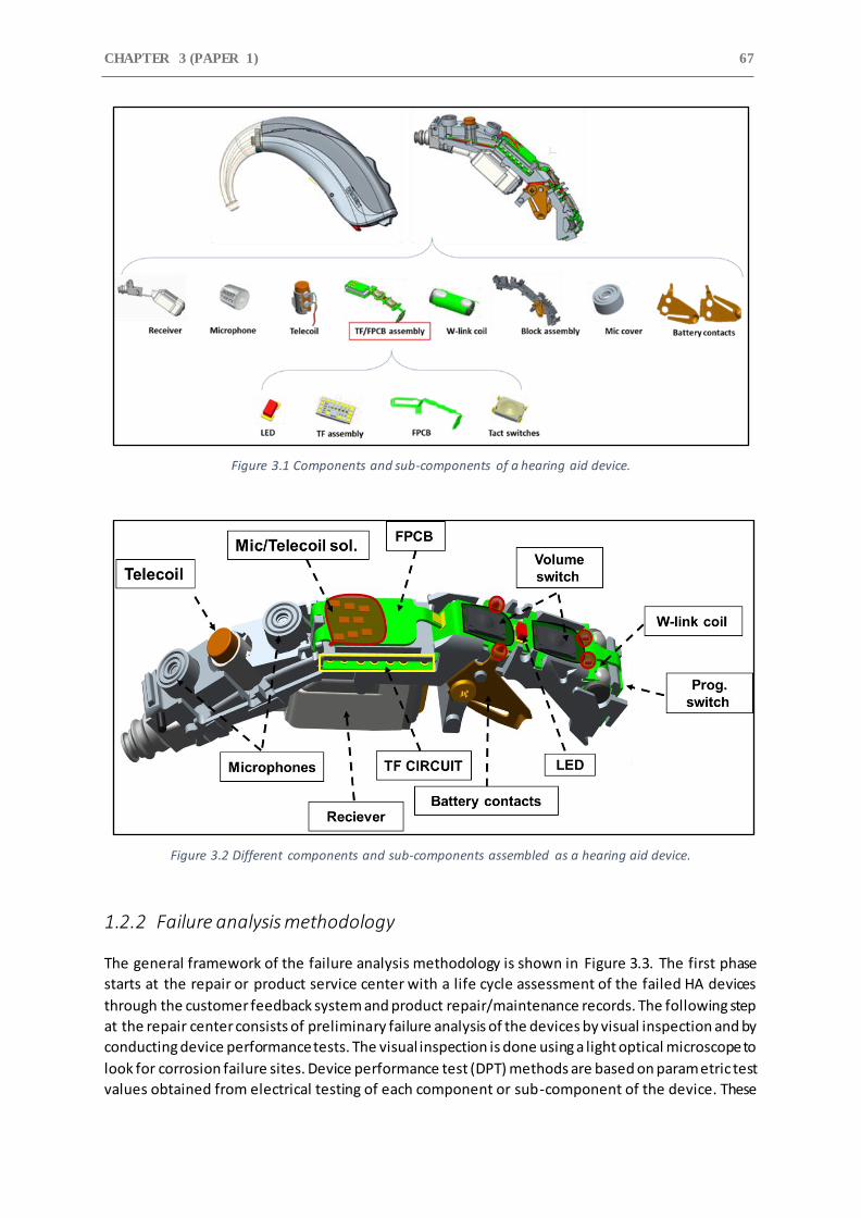
CHAPTER 3 (PAPER 1) 67
Figure 3.1 Components and sub-components of a hearing aid device.
Figure 3.2 Different components and sub-components assembled as a hearing aid device.
1.2.2 Failure analysis methodology
The general framework of the failure analysis methodology is shown in Figure 3.3. The first phase
starts at the repair or product service center with a life cycle assessment of the failed HA devices
through the customer feedback system and product repair/maintenance records. The following step
at the repair center consists of preliminary failure analysis of the devices by visual inspection and by
conducting device performance tests. The visual inspection is done using a light optical microscope to
look for corrosion failure sites. Device performance test (DPT) methods are based on parametric test
values obtained from electrical testing of each component or sub-component of the device. These
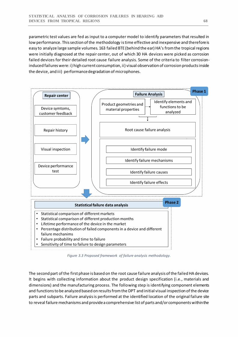
STATISTICAL ANALYSIS OF CORROSION FAILURES IN HEARING AID
DEVICES FROM TROPICAL REGIONS 68
parametric test values are fed as input to a computer model to identify parameters that resulted in
low performance. This section of the methodology is time effective and inexpensive and therefore is
easy to analyze large sample volumes. 163 failed BTE (behind the ear) HA’s from the tropical regions
were initially diagnosed at the repair center, out of which 30 HA devices were picked as corrosion
failed devices for their detailed root cause failure analysis. Some of the criteria to filter corrosion-
induced failures were: i) high current consumption, ii) visual observation of corrosion products inside
the device, and iii) performance degradation of microphones.
Figure 3.3 Proposed framework of failure analysis methodology.
The second part of the first phase is based on the root cause failure analysis of the failed HA devices.
It begins with collecting information about the product design specification (i.e., materials and
dimensions) and the manufacturing process. The following step is identifying component elements
and functions to be analyzed based on results from the DPT and initial visual inspection of the device
parts and subparts. Failure analysis is performed at the identified location of the original failure site
to reveal failure mechanisms and provide a comprehensive list of parts and/or components within the
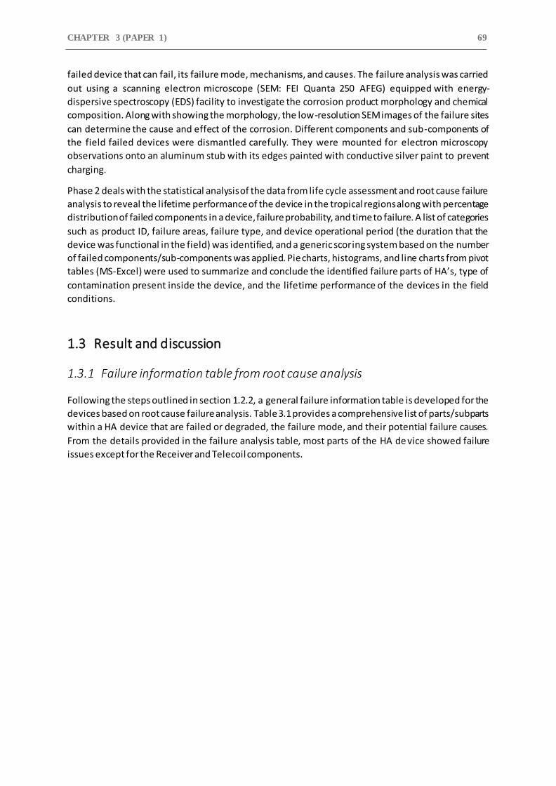
CHAPTER 3 (PAPER 1) 69
failed device that can fail, its failure mode, mechanisms, and causes. The failure analysis was carried
out using a scanning electron microscope (SEM: FEI Quanta 250 AFEG) equipped with energy-
dispersive spectroscopy (EDS) facility to investigate the corrosion product morphology and chemical
composition. Along with showing the morphology, the low-resolution SEM images of the failure sites
can determine the cause and effect of the corrosion. Different components and sub-components of
the field failed devices were dismantled carefully. They were mounted for electron microscopy
observations onto an aluminum stub with its edges painted with conductive silver paint to prevent
charging.
Phase 2 deals with the statistical analysis of the data from life cycle assessment and root cause failure
analysis to reveal the lifetime performance of the device in the tropical regions along with percentage
distribution of failed components in a device, failure probability, and time to failure. A list of categories
such as product ID, failure areas, failure type, and device operational period (the duration that the
device was functional in the field) was identified, and a generic scoring system based on the number
of failed components/sub-components was applied. Pie charts, histograms, and line charts from pivot
tables (MS-Excel) were used to summarize and conclude the identified failure parts of HA’s, type of
contamination present inside the device, and the lifetime performance of the devices in the field
conditions.
1.3 Result and discussion
1.3.1 Failure information table from root cause analysis
Following the steps outlined in section 1.2.2, a general failure information table is developed for the
devices based on root cause failure analysis. Table 3.1 provides a comprehensive list of parts/subparts
within a HA device that are failed or degraded, the failure mode, and their potential failure causes.
From the details provided in the failure analysis table, most parts of the HA de vice showed failure
issues except for the Receiver and Telecoil components.

STATISTICAL ANALYSIS OF CORROSION FAILURES IN HEARING AID
DEVICES FROM TROPICAL REGIONS 70
Table 3.1 Results derived from the root cause failure analysis of field failed HA devices.
Components Function Potential Failure Mode
Potential Failure Mechanisms
Battery Contacts Supply power output of 1.5 V from
ZAB to the device
Corros ion of contact surface Galvanic corrosion between metallic layers due to gold
poros ity Corros ion product accumulation at the contact
zone Contact surface damage due
to wear and fretting
Abrasive wear
FPCB & Hand Solderings Electrically connects microphones,
battery contacts, and coils to the FPCB
Corros ion of SAC solder alloys Delamination of conformal coating
Local ized corrosion attack, and Galvanic corrosion
TF Circuit Signal processing,
Audio and Information control
Corros ion of SMT components Electrochemical migration,
metallic corrosion products influencing performance
Shorted failures & leakage
current
Creep corrosion
Delamination of conformal
coating
W-link Coil Setup wireless l ink between HA pair
Detuning of the coil Metal lic corrosion products influencing performance
Microphones Coverts sound waves to an
electrical signal and then amplifies them
to an analog or digital signal
Corros ion of microphone electronic ci rcuitry
Electrochemical migration, metallic corrosion products
influencing performance
Increase in vibration sensitivity
of the membrane plate Increase in inherent noise level
Change in membrane mass
due to presence of corrosion products and contaminants.
Corros ion of Ni plated sound inlet grid
Clogged sound inlet
Volume & Prog. Switch Control HA sound volume & change
program modes
Corros ion of silver contact terminals and push dome
button
Presence of metallic corrosion products influencing
performance Electrochemical migration
Delamination of the protective Teflon switch cover
LED Shows ON/OFF Corros ion of LED terminals Presence of metallic corrosion
products between terminals caus ing leak current failure
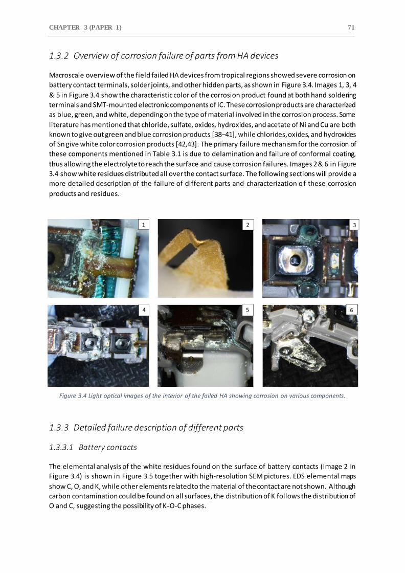
CHAPTER 3 (PAPER 1) 71
1.3.2 Overview of corrosion failure of parts from HA devices
Macroscale overview of the field failed HA devices from tropical regions showed severe corrosion on
battery contact terminals, solder joints, and other hidden parts, as shown in Figure 3.4. Images 1, 3, 4
& 5 in Figure 3.4 show the characteristic color of the corrosion product found at both hand soldering
terminals and SMT-mounted electronic components of IC. These corrosion products are characterized
as blue, green, and white, depending on the type of material involved in the corrosion process. Some
literature has mentioned that chloride, sulfate, oxides, hydroxides, and acetate of Ni and Cu are both
known to give out green and blue corrosion products [38–41], while chlorides, oxides, and hydroxides
of Sn give white color corrosion products [42,43]. The primary failure mechanism for the corrosion of
these components mentioned in Table 3.1 is due to delamination and failure of conformal coating,
thus allowing the electrolyte to reach the surface and cause corrosion failures. Images 2 & 6 in Figure
3.4 show white residues distributed all over the contact surface. The following sections will provide a
more detailed description of the failure of different parts and characterization of these corrosion
products and residues.
Figure 3.4 Light optical images of the interior of the failed HA showing corrosion on various components.
1.3.3 Detailed failure description of different parts
1.3.3.1 Battery contacts
The elemental analysis of the white residues found on the surface of battery contacts (image 2 in
Figure 3.4) is shown in Figure 3.5 together with high-resolution SEM pictures. EDS elemental maps
show C, O, and K, while other elements related to the material of the contact are not shown. Although
carbon contamination could be found on all surfaces, the distribution of K follows the distribution of
O and C, suggesting the possibility of K-O-C phases.
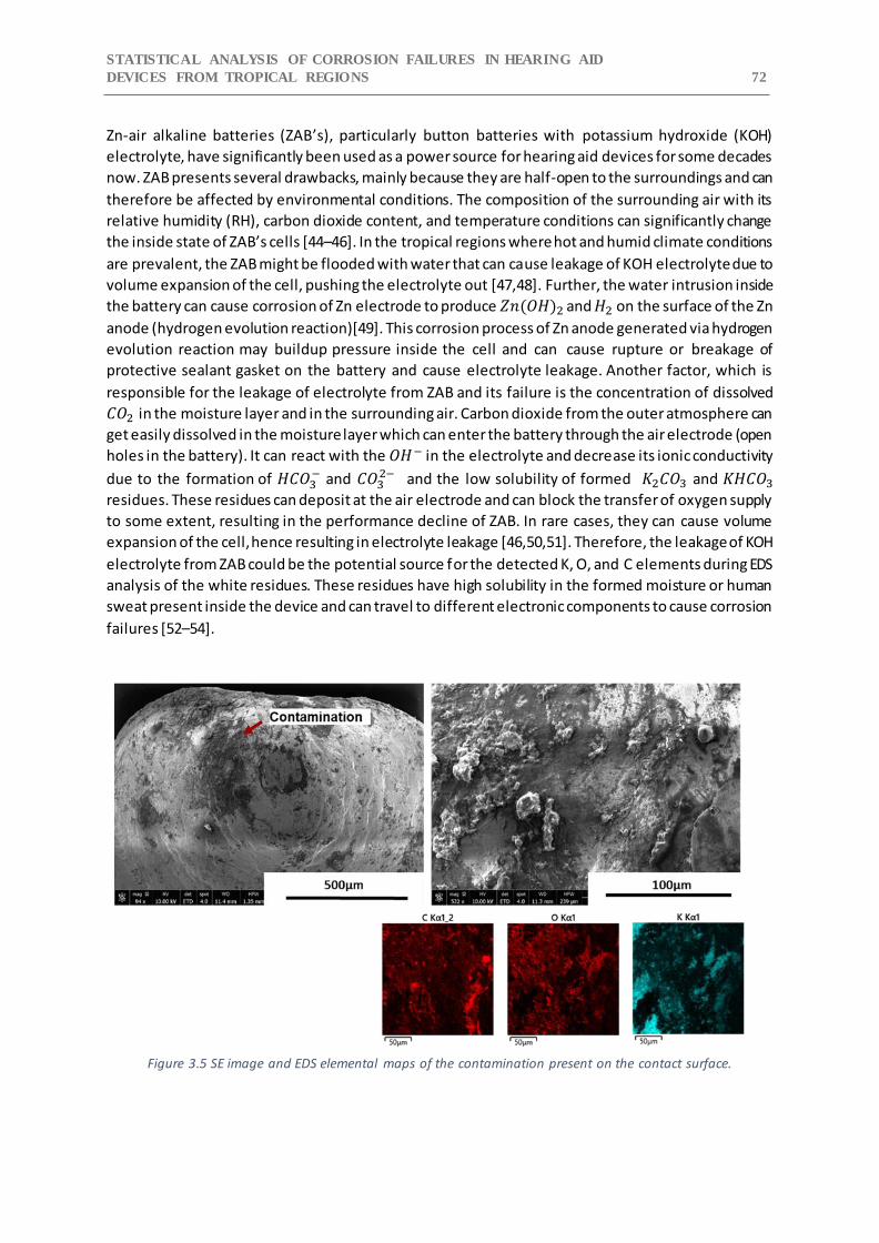
STATISTICAL ANALYSIS OF CORROSION FAILURES IN HEARING AID
DEVICES FROM TROPICAL REGIONS 72
Zn-air alkaline batteries (ZAB’s), particularly button batteries with potassium hydroxide (KOH)
electrolyte, have significantly been used as a power source for hearing aid devices for some decades
now. ZAB presents several drawbacks, mainly because they are half-open to the surroundings and can
therefore be affected by environmental conditions. The composition of the surrounding air with its
relative humidity (RH), carbon dioxide content, and temperature conditions can significantly change
the inside state of ZAB’s cells [44–46]. In the tropical regions where hot and humid climate conditions
are prevalent, the ZAB might be flooded with water that can cause leakage of KOH electrolyte due to
volume expansion of the cell, pushing the electrolyte out [47,48]. Further, the water intrusion inside
the battery can cause corrosion of Zn electrode to produce 𝑍𝑛(𝑂𝐻)2 and 𝐻2 on the surface of the Zn
anode (hydrogen evolution reaction)[49]. This corrosion process of Zn anode generated via hydrogen
evolution reaction may buildup pressure inside the cell and can cause rupture or breakage of
protective sealant gasket on the battery and cause electrolyte leakage. Another factor, which is
responsible for the leakage of electrolyte from ZAB and its failure is the concentration of dissolved
𝐶𝑂2 in the moisture layer and in the surrounding air. Carbon dioxide from the outer atmosphere can
get easily dissolved in the moisture layer which can enter the battery through the air electrode (open
holes in the battery). It can react with the 𝑂𝐻− in the electrolyte and decrease its ionic conductivity
due to the formation of 𝐻𝐶𝑂3− and 𝐶𝑂3
2− and the low solubility of formed 𝐾2𝐶𝑂3 and 𝐾𝐻𝐶𝑂3
residues. These residues can deposit at the air electrode and can block the transfer of oxygen supply
to some extent, resulting in the performance decline of ZAB. In rare cases, they can cause volume
expansion of the cell, hence resulting in electrolyte leakage [46,50,51]. Therefore, the leakage of KOH
electrolyte from ZAB could be the potential source for the detected K, O, and C elements during EDS
analysis of the white residues. These residues have high solubility in the formed moisture or human
sweat present inside the device and can travel to different electronic components to cause corrosion
failures [52–54].
Figure 3.5 SE image and EDS elemental maps of the contamination present on the contact surface.
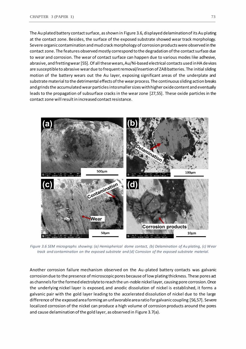
CHAPTER 3 (PAPER 1) 73
The Au plated battery contact surface, as shown in Figure 3.6, displayed delamination of its Au plating
at the contact zone. Besides, the surface of the exposed substrate showed wear track morphology.
Severe organic contamination and mud crack morphology of corrosion products were observed in the
contact zone. The features observed mostly correspond to the degradation of the contact surface due
to wear and corrosion. The wear of contact surface can happen due to various modes like adhesive,
abrasive, and fretting wear [55]. Of all these wears, Au/Ni-based electrical contacts used in HA devices
are susceptible to abrasive wear due to frequent removal/insertion of ZAB batteries. The initial sliding
motion of the battery wears out the Au layer, exposing significant areas of the underplate and
substrate material to the detrimental effects of the wear process. The continuous sliding action breaks
and grinds the accumulated wear particles into smaller sizes with higher oxide content and eventually
leads to the propagation of subsurface cracks in the wear zone [27,55]. These oxide particles in the
contact zone will result in increased contact resistance.
Figure 3.6 SEM micrographs showing: (a) Hemispherical dome contact, (b) Delamination of Au plating, (c) Wear
track and contamination on the exposed substrate and (d) Corrosion of the exposed substrate material.
Another corrosion failure mechanism observed on the Au-plated battery contacts was galvanic
corrosion due to the presence of microscopic pores because of low plating thickness. These pores act
as channels for the formed electrolyte to reach the un-noble nickel layer, causing pore corrosion. Once
the underlying nickel layer is exposed, and anodic dissolution of nickel is established, it forms a
galvanic pair with the gold layer leading to the accelerated dissolution of nickel due to the large
difference of the exposed area forming an unfavorable area ratio for galvanic coupling [56,57]. Severe
localized corrosion of the nickel can produce a high volume of corrosion products around the pores
and cause delamination of the gold layer, as observed in Figure 3.7(a).
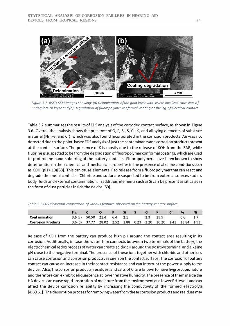
STATISTICAL ANALYSIS OF CORROSION FAILURES IN HEARING AID
DEVICES FROM TROPICAL REGIONS 74
Figure 3.7 BSED SEM images showing: (a) Delamination of the gold layer with severe localized corrosion of
underplate Ni layer and (b) Degradation of fluoropolymer conformal coating at the leg of electrical contact.
Table 3.2 summarizes the results of EDS analysis of the corroded contact surface, as shown in Figure
3.6. Overall the analysis shows the presence of O, F, Si, S, Cl, K, and alloying elements of substrate
material (Ni, Fe, and Cr), which was also found incorporated in the corrosion products. Au was not
detected due to the point-based EDS analysis of just the contaminants and corrosion products present
at the contact surface. The presence of K is mostly due to the release of KOH from the ZAB, while
fluorine is suspected to be from the degradation of fluoropolymer conformal coatings, which are used
to protect the hand soldering of the battery contacts. Fluoropolymers have been known to show
deterioration in their chemical and mechanical properties in the presence of alkaline conditions such
as KOH (pH > 10)[58]. This can cause elemental F to release from a fluoropolymer that can react and
degrade the metal contacts. Chloride and sulfur are suspected to be from external sources such as
body fluids and external contamination. In addition, elements such as Si can be present as silicates in
the form of dust particles inside the device [59].
Table 3.2 EDS elemental comparison of various features observed on the battery contact surface.
Fig. C O F Si S Cl K Cr Fe Ni
Contamination 3.6 (c) 50.50 21.4 6.4 2.1 2.3 15.5 0.6 1.7
Corrosion Products 3.6 (d) 37.77 28.02 2.52 1.88 0.23 2.20 10.20 1.41 13.84 1.93
Release of KOH from the battery can produce high pH around the contact area resulting in its
corrosion. Additionally, in case the water film connects between two terminals of the battery, the
electrochemical redox process of water can create acidic pH around the positive terminal and alkaline
pH close to the negative terminal. The presence of these ions together with chloride and other ions
can cause corrosion and corrosion products, as seen on the contact surface. The corrosion of battery
contact can cause an increase in their contact resistance and can interrupt the power supply to the
device . Also, the corrosion products, residues, and salts of Cl are known to have hygroscopic nature
and therefore can exhibit deliquescence at lower relative humidity. The presence of them inside the
HA device can cause rapid absorption of moisture from the environment at a lower RH levels and can
affect the device corrosion reliability by increasing the conductivity of the formed e lectrolyte
[4,60,61]. The desorption process for removing water from these corrosion products and residues may
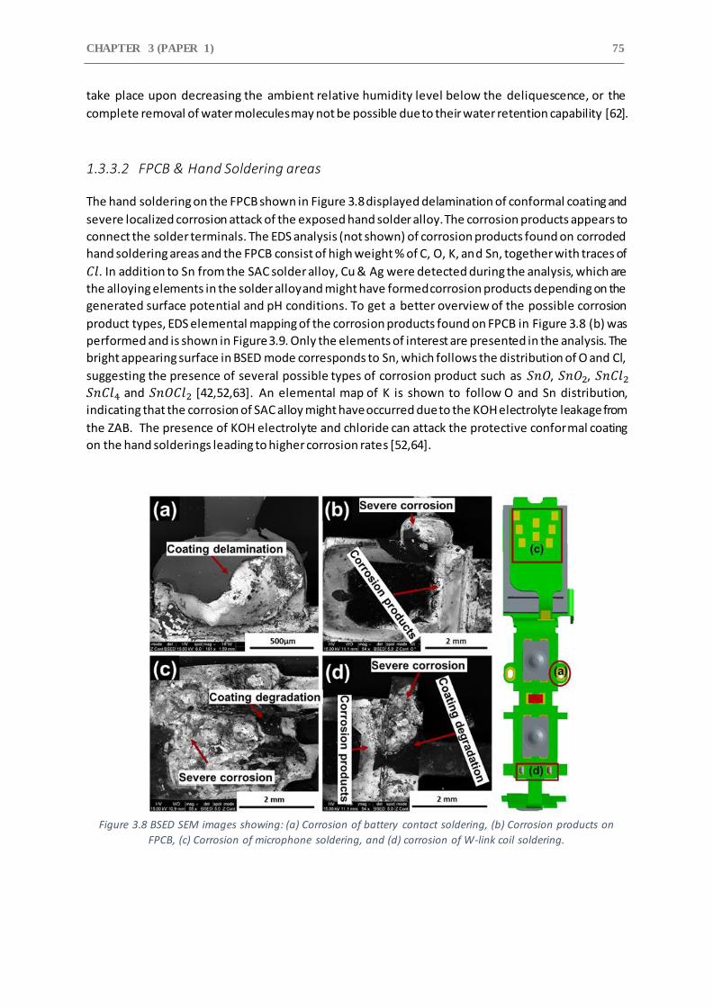
CHAPTER 3 (PAPER 1) 75
take place upon decreasing the ambient relative humidity level below the deliquescence, or the
complete removal of water molecules may not be possible due to their water retention capability [62].
1.3.3.2 FPCB & Hand Soldering areas
The hand soldering on the FPCB shown in Figure 3.8 displayed delamination of conformal coating and
severe localized corrosion attack of the exposed hand solder alloy. The corrosion products appears to
connect the solder terminals. The EDS analysis (not shown) of corrosion products found on corroded
hand soldering areas and the FPCB consist of high weight % of C, O, K, and Sn, together with traces of
𝐶𝑙. In addition to Sn from the SAC solder alloy, Cu & Ag were detected during the analysis, which are
the alloying elements in the solder alloy and might have formed corrosion products depending on the
generated surface potential and pH conditions. To get a better overview of the possible corrosion
product types, EDS elemental mapping of the corrosion products found on FPCB in Figure 3.8 (b) was
performed and is shown in Figure 3.9. Only the elements of interest are presented in the analysis. The
bright appearing surface in BSED mode corresponds to Sn, which follows the distribution of O and Cl,
suggesting the presence of several possible types of corrosion product such as 𝑆𝑛𝑂, 𝑆𝑛𝑂2, 𝑆𝑛𝐶𝑙2
𝑆𝑛𝐶𝑙4 and 𝑆𝑛𝑂𝐶𝑙2 [42,52,63]. An elemental map of K is shown to follow O and Sn distribution,
indicating that the corrosion of SAC alloy might have occurred due to the KOH electrolyte leakage from
the ZAB. The presence of KOH electrolyte and chloride can attack the protective conformal coating
on the hand solderings leading to higher corrosion rates [52,64].
Figure 3.8 BSED SEM images showing: (a) Corrosion of battery contact soldering, (b) Corrosion products on
FPCB, (c) Corrosion of microphone soldering, and (d) corrosion of W-link coil soldering.
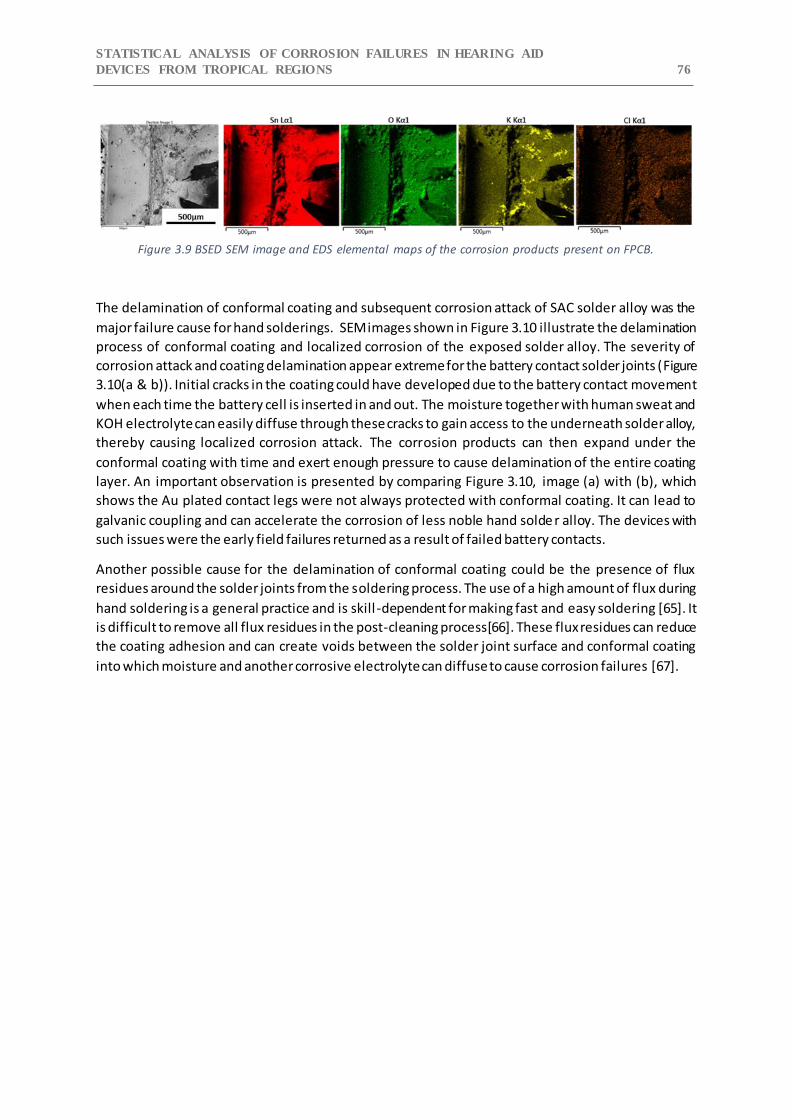
STATISTICAL ANALYSIS OF CORROSION FAILURES IN HEARING AID
DEVICES FROM TROPICAL REGIONS 76
Figure 3.9 BSED SEM image and EDS elemental maps of the corrosion products present on FPCB.
The delamination of conformal coating and subsequent corrosion attack of SAC solder alloy was the
major failure cause for hand solderings. SEM images shown in Figure 3.10 illustrate the delamination
process of conformal coating and localized corrosion of the exposed solder alloy. The severity of
corrosion attack and coating delamination appear extreme for the battery contact solder joints (Figure
3.10(a & b)). Initial cracks in the coating could have developed due to the battery contact movement
when each time the battery cell is inserted in and out. The moisture together with human sweat and
KOH electrolyte can easily diffuse through these cracks to gain access to the underneath solder alloy,
thereby causing localized corrosion attack. The corrosion products can then expand under the
conformal coating with time and exert enough pressure to cause delamination of the entire coating
layer. An important observation is presented by comparing Figure 3.10, image (a) with (b), which
shows the Au plated contact legs were not always protected with conformal coating. It can lead to
galvanic coupling and can accelerate the corrosion of less noble hand solde r alloy. The devices with
such issues were the early field failures returned as a result of failed battery contacts.
Another possible cause for the delamination of conformal coating could be the presence of flux
residues around the solder joints from the soldering process. The use of a high amount of flux during
hand soldering is a general practice and is skill -dependent for making fast and easy soldering [65]. It
is difficult to remove all flux residues in the post-cleaning process[66]. These flux residues can reduce
the coating adhesion and can create voids between the solder joint surface and conformal coating
into which moisture and another corrosive electrolyte can diffuse to cause corrosion failures [67].
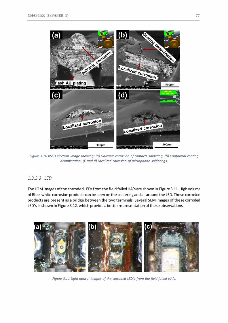
CHAPTER 3 (PAPER 1) 77
Figure 3.10 BSED electron image showing: (a) Galvanic corrosion of contacts soldering, (b) Conformal coating
delamination, (C and d) Localized corrosion of microphone solderings.
1.3.3.3 LED
The LOM images of the corroded LEDs from the field failed HA’s are shown in Figure 3.11. High volume
of Blue-white corrosion products can be seen on the soldering and all around the LED. These corrosion
products are present as a bridge between the two terminals. Several SEM images of these corroded
LED’s is shown in Figure 3.12, which provide a better representation of these observations.
Figure 3.11 Light optical images of the corroded LED’s from the field failed HA’s.
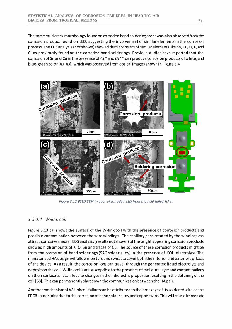
STATISTICAL ANALYSIS OF CORROSION FAILURES IN HEARING AID
DEVICES FROM TROPICAL REGIONS 78
The same mud crack morphology found on corroded hand soldering areas was also observed from the
corrosion product found on LED, suggesting the involvement of similar elements in the corrosion
process. The EDS analysis (not shown) showed that it consists of similar elements like Sn, Cu, O, K, and
Cl as previously found on the corroded hand solderings. Previous studies have reported that the
corrosion of Sn and Cu in the presence of 𝐶𝑙− and 𝑂𝐻− can produce corrosion products of white, and
blue-green color [40–43], which was observed from optical images shown in Figure 3.4
Figure 3.12 BSED SEM images of corroded LED from the field failed HA’s.
1.3.3.4 W-link coil
Figure 3.13 (a) shows the surface of the W-link coil with the presence of corrosion products and
possible contamination between the wire windings. The capillary gaps created by the windings can
attract corrosive media. EDS analysis (results not shown) of the bright appearing corrosion products
showed high amounts of K, O, Sn and traces of Cu. The source of these corrosion products might be
from the corrosion of hand solderings (SAC solder alloy) in the presence of KOH electrolyte. The
miniaturized HA design will allow moisture and sweat to cover both the interior and exterior surfaces
of the device. As a result, the corrosion ions can travel through the generated liquid electrolyte and
deposit on the coil. W-link coils are susceptible to the presence of moisture layer and contaminations
on their surface as it can lead to changes in their dielectric properties resulting in the detuning of the
coil [68]. This can permanently shut down the communication between the HA pair.
Another mechanism of W-link coil failure can be attributed to the breakage of its soldered wire on the
FPCB solder joint due to the corrosion of hand solder alloy and copper wire. This will caus e immediate
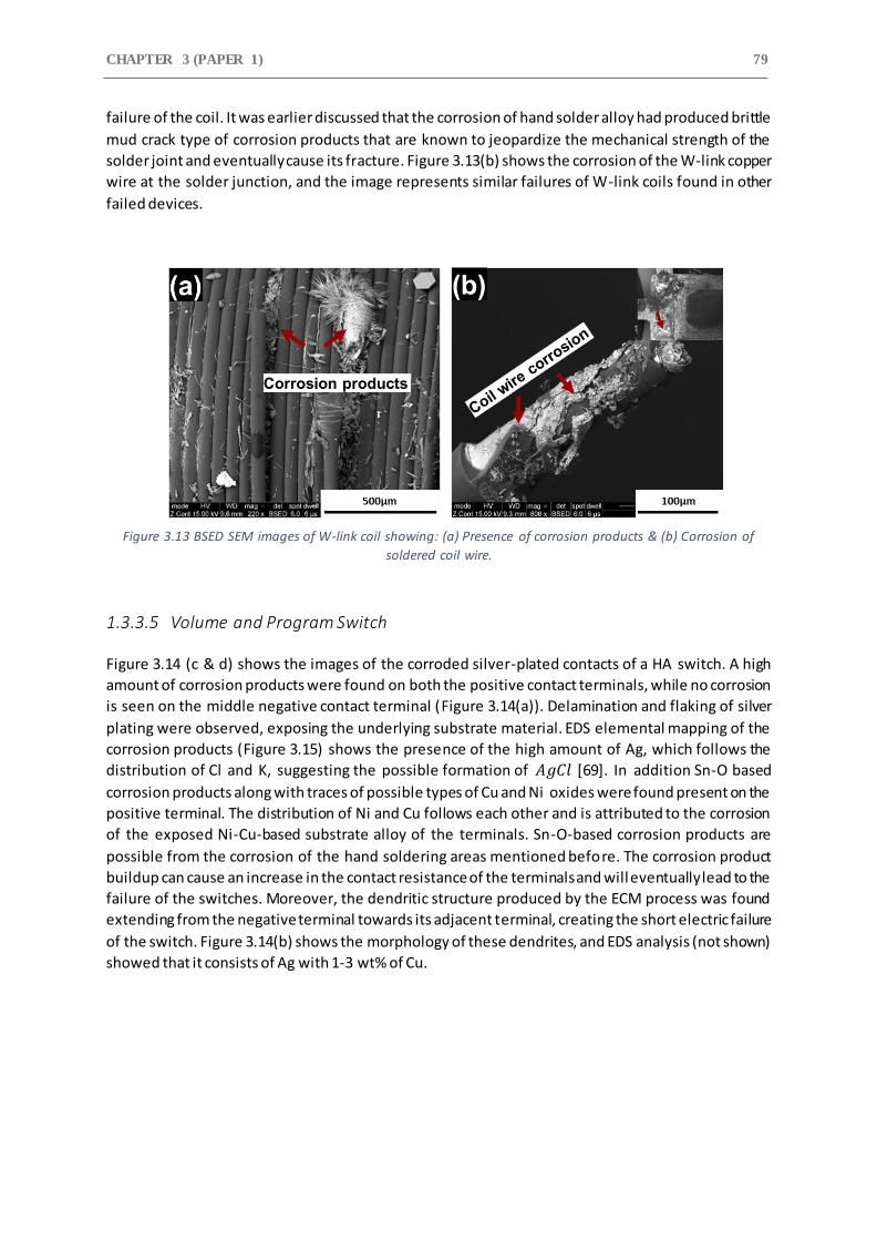
CHAPTER 3 (PAPER 1) 79
failure of the coil. It was earlier discussed that the corrosion of hand solder alloy had produced brittle
mud crack type of corrosion products that are known to jeopardize the mechanical strength of the
solder joint and eventually cause its fracture. Figure 3.13(b) shows the corrosion of the W-link copper
wire at the solder junction, and the image represents similar failures of W-link coils found in other
failed devices.
Figure 3.13 BSED SEM images of W-link coil showing: (a) Presence of corrosion products & (b) Corrosion of
soldered coil wire.
1.3.3.5 Volume and Program Switch
Figure 3.14 (c & d) shows the images of the corroded silver-plated contacts of a HA switch. A high
amount of corrosion products were found on both the positive contact terminals, while no corrosion
is seen on the middle negative contact terminal (Figure 3.14(a)). Delamination and flaking of silver
plating were observed, exposing the underlying substrate material. EDS elemental mapping of the
corrosion products (Figure 3.15) shows the presence of the high amount of Ag, which follows the
distribution of Cl and K, suggesting the possible formation of 𝐴𝑔𝐶𝑙 [69]. In addition Sn-O based
corrosion products along with traces of possible types of Cu and Ni oxides were found present on the
positive terminal. The distribution of Ni and Cu follows each other and is attributed to the corrosion
of the exposed Ni-Cu-based substrate alloy of the terminals. Sn-O-based corrosion products are
possible from the corrosion of the hand soldering areas mentioned before. The corrosion product
buildup can cause an increase in the contact resistance of the terminals and will eventually lead to the
failure of the switches. Moreover, the dendritic structure produced by the ECM process was found
extending from the negative terminal towards its adjacent terminal, creating the short electric failure
of the switch. Figure 3.14(b) shows the morphology of these dendrites, and EDS analysis (not shown)
showed that it consists of Ag with 1-3 wt% of Cu.
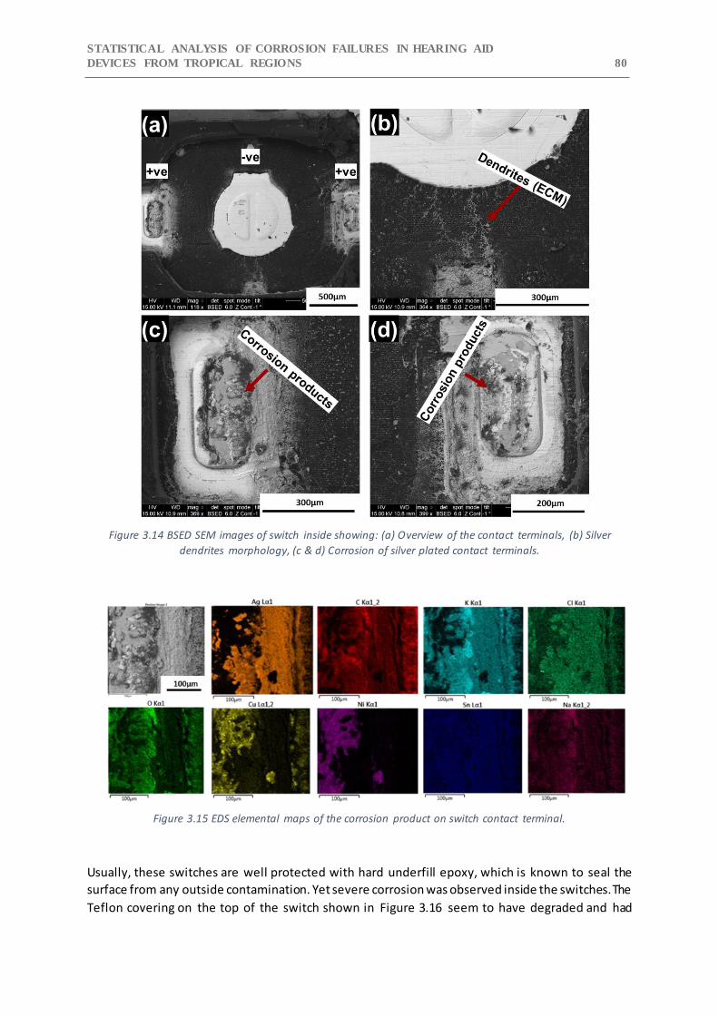
STATISTICAL ANALYSIS OF CORROSION FAILURES IN HEARING AID
DEVICES FROM TROPICAL REGIONS 80
Figure 3.14 BSED SEM images of switch inside showing: (a) Overview of the contact terminals, (b) Silver
dendrites morphology, (c & d) Corrosion of silver plated contact terminals.
Figure 3.15 EDS elemental maps of the corrosion product on switch contact terminal.
Usually, these switches are well protected with hard underfill epoxy, which is known to seal the
surface from any outside contamination. Yet severe corrosion was observed inside the switches. The
Teflon covering on the top of the switch shown in Figure 3.16 seem to have degraded and had
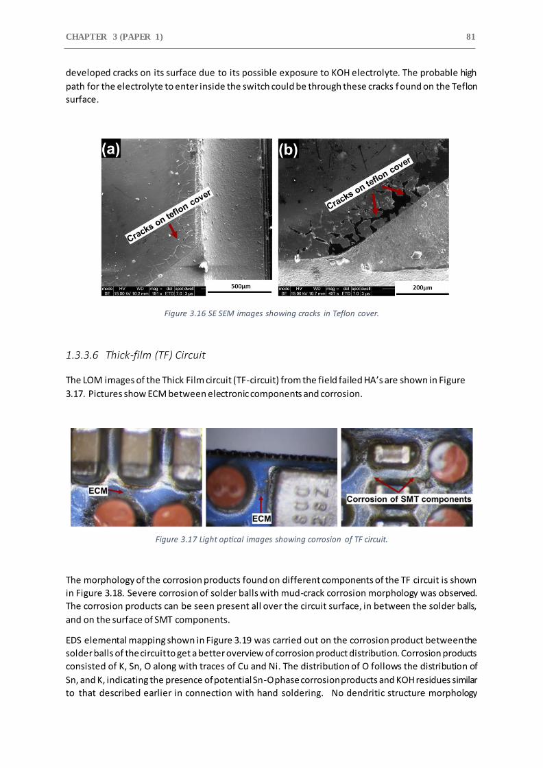
CHAPTER 3 (PAPER 1) 81
developed cracks on its surface due to its possible exposure to KOH electrolyte. The probable high
path for the electrolyte to enter inside the switch could be through these cracks f ound on the Teflon
surface.
Figure 3.16 SE SEM images showing cracks in Teflon cover.
1.3.3.6 Thick-film (TF) Circuit
The LOM images of the Thick Film circuit (TF-circuit) from the field failed HA’s are shown in Figure
3.17. Pictures show ECM between electronic components and corrosion.
Figure 3.17 Light optical images showing corrosion of TF circuit.
The morphology of the corrosion products found on different components of the TF circuit is shown
in Figure 3.18. Severe corrosion of solder balls with mud-crack corrosion morphology was observed.
The corrosion products can be seen present all over the circuit surface, in between the solder balls,
and on the surface of SMT components.
EDS elemental mapping shown in Figure 3.19 was carried out on the corrosion product between the
solder balls of the circuit to get a better overview of corrosion product distribution. Corrosion products
consisted of K, Sn, O along with traces of Cu and Ni. The distribution of O follows the distribution of
Sn, and K, indicating the presence of potential Sn-O phase corrosion products and KOH residues similar
to that described earlier in connection with hand soldering. No dendritic structure morphology
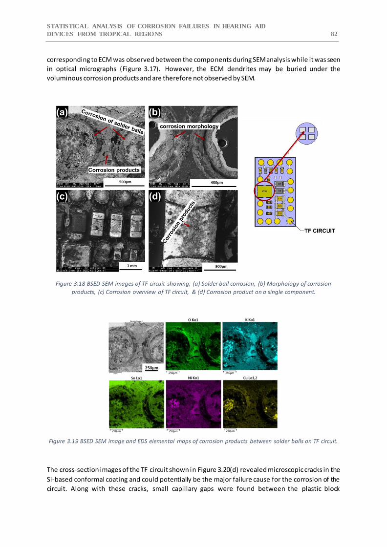
STATISTICAL ANALYSIS OF CORROSION FAILURES IN HEARING AID
DEVICES FROM TROPICAL REGIONS 82
corresponding to ECM was observed between the components during SEM analysis while it was seen
in optical micrographs (Figure 3.17). However, the ECM dendrites may be buried under the
voluminous corrosion products and are therefore not observed by SEM.
Figure 3.18 BSED SEM images of TF circuit showing, (a) Solder ball corrosion, (b) Morphology of corrosion
products, (c) Corrosion overview of TF circuit, & (d) Corrosion product on a single component.
Figure 3.19 BSED SEM image and EDS elemental maps of corrosion products between solder balls on TF circuit.
The cross-section images of the TF circuit shown in Figure 3.20(d) revealed microscopic cracks in the
Si-based conformal coating and could potentially be the major failure cause for the corrosion of the
circuit. Along with these cracks, small capillary gaps were found between the plastic block
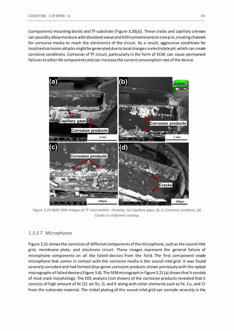
CHAPTER 3 (PAPER 1) 83
(components mounting block) and TF substrate (Figure 3.20(a)). These cracks and capillary crevices
can possibly allow moisture with dissolved sweat and KOH contaminants to cree p in, creating channels
for corrosive media to reach the electronics of the circuit. As a result, aggressive conditions for
localized corrosion attacks might be generated due to local changes in electrolyte pH, which can create
corrosive conditions. Corrosion of TF circuit, particularly in the form of ECM, can cause permanent
failures to other HA components and can increase the current consumption rate of the device.
Figure 3.20 BSED SEM images of TF cross-section showing: (a) Capillary gaps, (b, c) Corrosion products, (d)
Cracks in conformal coating.
1.3.3.7 Microphones
Figure 3.21 shows the corrosion of different components of the microphone, such as the sound inlet
grid, membrane plate, and electronic circuit. These images represent the general failure of
microphone components on all the failed devices from the field. The first component inside
microphone that comes in contact with the corrosive media is the sound-inlet grid. It was found
severely corroded and had formed blue-green corrosion products shown previously with the optical
macrographs of failed devices (Figure 3.4). The SEM micrograph in Figure 3.21 (a) shows that it consists
of mud crack morphology. The EDS analysis (not shown) of the corrosion products revealed that it
consists of high amount of Ni (21 wt.%), O, and K along with other elements such as Fe, Cu, and Cr
from the substrate material. The nickel plating of the sound-inlet grid can corrode severely in the
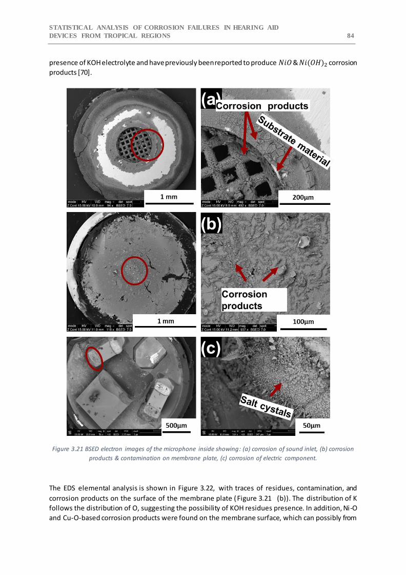
STATISTICAL ANALYSIS OF CORROSION FAILURES IN HEARING AID
DEVICES FROM TROPICAL REGIONS 84
presence of KOH electrolyte and have previously been reported to produce 𝑁𝑖𝑂 & 𝑁𝑖(𝑂𝐻)2 corrosion
products [70].
Figure 3.21 BSED electron images of the microphone inside showing: (a) corrosion of sound inlet, (b) corrosion
products & contamination on membrane plate, (c) corrosion of electric component.
The EDS elemental analysis is shown in Figure 3.22, with traces of residues, contamination, and
corrosion products on the surface of the membrane plate (Figure 3.21 (b)). The distribution of K
follows the distribution of O, suggesting the possibility of KOH residues presence. In addition, Ni-O
and Cu-O-based corrosion products were found on the membrane surface, which can possibly from

CHAPTER 3 (PAPER 1) 85
the corrosion of the sound inlet grid and from the corrosion of hand solderings. The corrosion products
of SAC solder alloy from hand solderings and residues of KOH can easily get dissolved in the present
human sweat and moisture layer inside the device, which connects and bridges other components.
The mobility of ions such as 𝐶𝑙− and 𝑂𝐻− towards microphone membrane plate can increase under
the influence of high electric field created by the availability of high electric charge on the membrane
plate and therefore can preferentially deposit on its surface.
Figure 3.21(c) show the corrosion of the microphones electronic circuit. The solder legs of the
capacitors were found corroded. The corrosion morphology shows the presence of growing dendrites
and crystals. The EDS analysis (not shown) of the corrosion products found on the surface of the
electronic component showed that it consist of Sn, O, and high amount of Cl (9 wt.%), suggesting the
possibility of similar type of corrosion products found previously on hand solderings and TF-circuit
components. The presence of such a high amount of Cl salts suggests that microphones are more
vulnerable to corrosion attack due to human sweat. This again points out to the presence of a high
electric charge on the membrane plate as a cause for its increased corrosion attack.
Figure 3.22 EDS elemental mapping of corrosion products and contamination found of microphone membrane
plate.
1.3.4 Statistical Failure Analysis of Failure Data
Figure 3.23 shows the percentage distribution of HA components that undergone corrosion during
application. The failure distribution is divided into “failed” and “prone” categories based on the device
performance test (DPT) and root cause failure analysis. The failed components were reported
nonfunctional after the DPT. The prone to failure components did not show any functionality issues
but showed some degree of corrosion or presence of salt and KOH residues during SEM-EDS analysis.
Hence, the assumption is that the “prone” components can show failure over a period of time if they
are continued to be operated in the field.
As shown in Figure 3.23, 100% failure risk (Prone + failed types) exists for Thick Film (TF) circuits,
battery contact solderings, W-link coil solderings, battery contacts, FPCB, and LED. The high failure risk
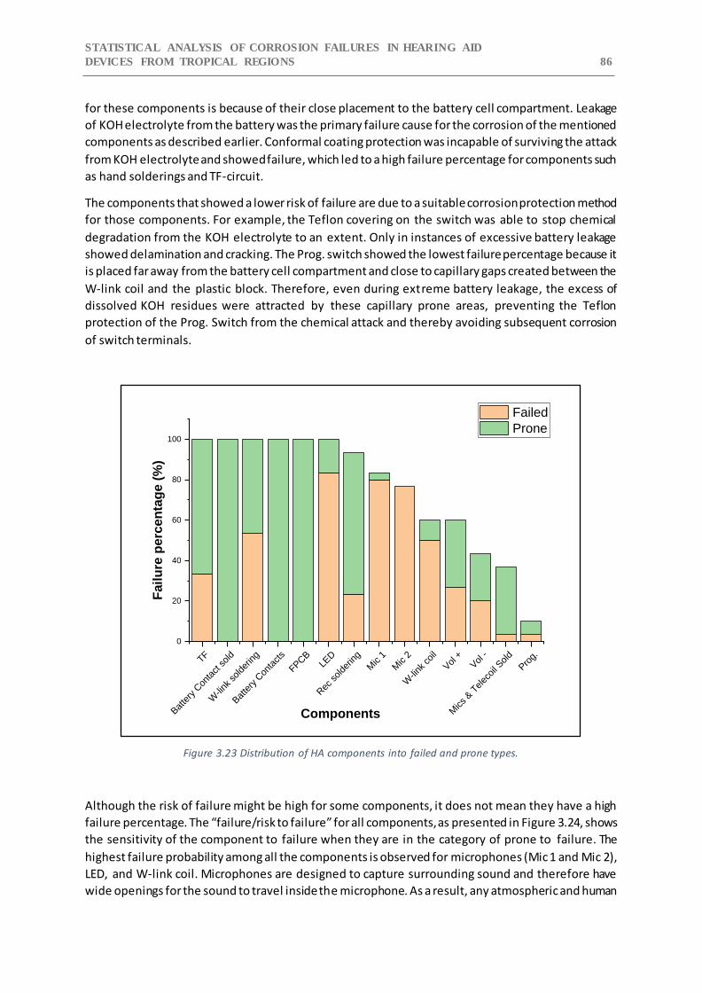
STATISTICAL ANALYSIS OF CORROSION FAILURES IN HEARING AID
DEVICES FROM TROPICAL REGIONS 86
for these components is because of their close placement to the battery cell compartment. Leakage
of KOH electrolyte from the battery was the primary failure cause for the corrosion of the mentioned
components as described earlier. Conformal coating protection was incapable of surviving the attack
from KOH electrolyte and showed failure, which led to a high failure percentage for components such
as hand solderings and TF-circuit.
The components that showed a lower risk of failure are due to a suitable corrosion protection method
for those components. For example, the Teflon covering on the switch was able to stop chemical
degradation from the KOH electrolyte to an extent. Only in instances of excessive battery leakage
showed delamination and cracking. The Prog. switch showed the lowest failure percentage because it
is placed far away from the battery cell compartment and close to capillary gaps created between the
W-link coil and the plastic block. Therefore, even during extreme battery leakage, the excess of
dissolved KOH residues were attracted by these capillary prone areas, preventing the Teflon
protection of the Prog. Switch from the chemical attack and thereby avoiding subsequent corrosion
of switch terminals.
Figure 3.23 Distribution of HA components into failed and prone types.
Although the risk of failure might be high for some components, it does not mean they have a high
failure percentage. The “failure/risk to failure” for all components, as presented in Figure 3.24, shows
the sensitivity of the component to failure when they are in the category of prone to failure. The
highest failure probability among all the components is observed for microphones (Mic 1 and Mic 2),
LED, and W-link coil. Microphones are designed to capture surrounding sound and therefore have
wide openings for the sound to travel inside the microphone. As a result, any atmospheric and human
TF
Bat
tery
Con
tact sold
W-link
solde
ring
Bat
tery
Con
tacts
FPCB
LED
Rec
solde
ring
Mic 1
Mic 2
W-link
coil
Vol +
Vol -
Mics & T
elec
oil S
old
Pro
g.
0
20
40
60
80
100
Fail
ure
perc
en
tag
e (
%)
Components
Failed
Prone
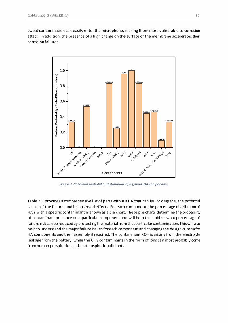
CHAPTER 3 (PAPER 1) 87
sweat contamination can easily enter the microphone, making them more vulnerable to corrosion
attack. In addition, the presence of a high charge on the surface of the membrane accelerates their
corrosion failures.
Figure 3.24 Failure probability distribution of different HA components.
Table 3.3 provides a comprehensive list of parts within a HA that can fail or degrade, the potential
causes of the failure, and its observed effects. For each component, the percentage distribution of
HA’s with a specific contaminant is shown as a pie chart. These pie charts determine the probability
of contaminant presence on a particular component and will help to establish what percentage of
failure risk can be reduced by protecting the material from that particular contamination. This will also
help to understand the major failure issues for each component and changing the design criteria for
HA components and their assembly if required. The contaminant KOH is arising from the electrolyte
leakage from the battery, while the Cl, S contaminants in the form of ions can most probably come
from human perspiration and as atmospheric pollutants.
0,33333
0
0,53333
0 0
0,83333
0,25
0,96
1
0,83333
0,444440,46154
0,09091
0,33333
TF
Bat
tery
Con
tact
solde
ring
W-link
solde
ring
Bat
tery
Con
tact
s
FPCB
LED
Rec
solde
ring
Mic 1
Mic 2
W-link
coil
Vol +
Vol -
Mics & T
elec
oil S
olde
rings
Pro
g.
0,0
0,2
0,4
0,6
0,8
1,0
Fa
ilu
re P
rob
ab
ilit
y (
Fa
ile
d/R
isk
of
fail
ure
)
Components

STATISTICAL ANALYSIS OF CORROSION FAILURES IN HEARING AID
DEVICES FROM TROPICAL REGIONS 88
Table 3.3 Failure cause and effect table.
Components Observed Effect Potential Failure Cause Percentage distribution of HA’s with specific contaminant
Battery Contact Increase contact resistance, loss of
contact force, high power consumption
Leakage of HA battery, human perspiration, and
atmospheric contamination
High power
consumption, increase contact resistance
Friction, vibrations,
and mechanical movement
FPCB & Hand Solderings High power consumption, intermittent
device failure, and solder joint fall off
human perspiration, humidity, temperature, and leakage of HA battery
Intermittent
electric short, high power consumption
poor adhesion between the
copper layers, human perspiration, moisture ingress, temperature, and leakage of HA battery
TF Circuit High power consumption, intermittent
failure
Flux residues, Moisture ingress, human perspiration, and leakage of HA battery
W-link Coil No
communication between the HA pair
Moisture ingress, human
perspiration, and leakage of HA battery
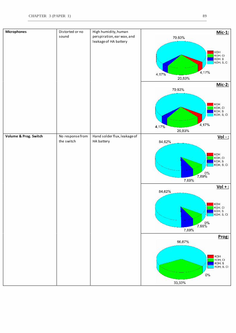
CHAPTER 3 (PAPER 1) 89
Microphones Distorted or no sound
High humidity, human perspiration, ear wax, and
leakage of HA battery
Mic-1:
Mic-2:
Volume & Prog. Switch No response from
the switch
Hand solder flux, leakage of
HA battery Vol - :
Vol + :
Prog:
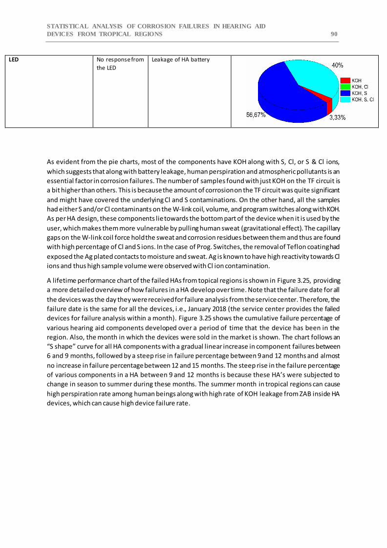
STATISTICAL ANALYSIS OF CORROSION FAILURES IN HEARING AID
DEVICES FROM TROPICAL REGIONS 90
LED No response from
the LED
Leakage of HA battery
As evident from the pie charts, most of the components have KOH along with S, Cl, or S & Cl ions,
which suggests that along with battery leakage, human perspiration and atmospheric pollutants is an
essential factor in corrosion failures. The number of samples found with just KOH on the TF circuit is
a bit higher than others. This is because the amount of corrosion on the TF circuit was quite significant
and might have covered the underlying Cl and S contaminations. On the other hand, all the samples
had either S and/or Cl contaminants on the W-link coil, volume, and program switches along with KOH.
As per HA design, these components lie towards the bottom part of the device when it is used by the
user, which makes them more vulnerable by pulling human sweat (gravitational effect). The capillary
gaps on the W-link coil force hold the sweat and corrosion residues between them and thus are found
with high percentage of Cl and S ions. In the case of Prog. Switches, the removal of Teflon coating had
exposed the Ag plated contacts to moisture and sweat. Ag is known to have high reactivity towards Cl
ions and thus high sample volume were observed with Cl ion contamination.
A lifetime performance chart of the failed HAs from topical regions is shown in Figure 3.25, providing
a more detailed overview of how failures in a HA develop over time. Note that the failure date for all
the devices was the day they were received for failure analysis from the service center. Therefore, the
failure date is the same for all the devices, i.e., January 2018 (the service center provides the failed
devices for failure analysis within a month). Figure 3.25 shows the cumulative failure percentage of
various hearing aid components developed over a period of time that the device has been in the
region. Also, the month in which the devices were sold in the market is shown. The chart follows an
“S shape” curve for all HA components with a gradual linear increase in component failures between
6 and 9 months, followed by a steep rise in failure percentage between 9 and 12 months and almost
no increase in failure percentage between 12 and 15 months. The steep rise in the failure percentage
of various components in a HA between 9 and 12 months is because these HA’s were subjected to
change in season to summer during these months. The summer month in tropical regions can cause
high perspiration rate among human beings along with high rate of KOH leakage from ZAB inside HA
devices, which can cause high device failure rate.
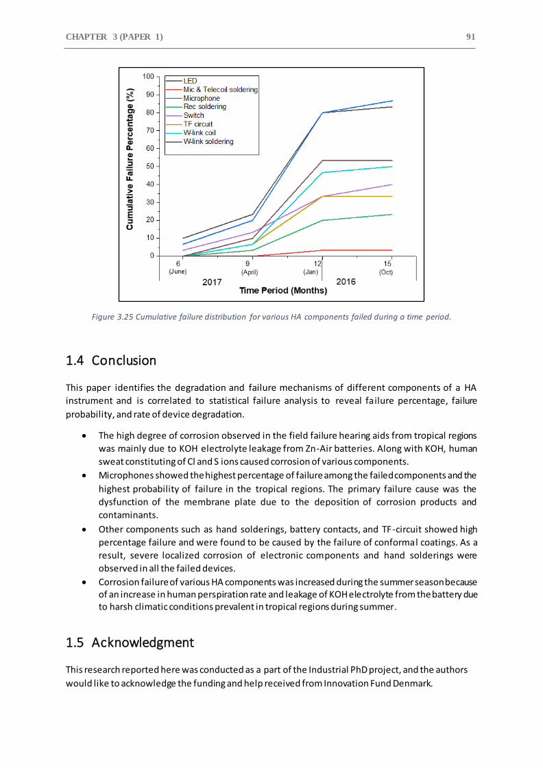
CHAPTER 3 (PAPER 1) 91
Figure 3.25 Cumulative failure distribution for various HA components failed during a time period.
1.4 Conclusion
This paper identifies the degradation and failure mechanisms of different components of a HA
instrument and is correlated to statistical failure analysis to reveal failure percentage, failure
probability, and rate of device degradation.
The high degree of corrosion observed in the field failure hearing aids from tropical regions
was mainly due to KOH electrolyte leakage from Zn-Air batteries. Along with KOH, human
sweat constituting of Cl and S ions caused corrosion of various components.
Microphones showed the highest percentage of failure among the failed components and the
highest probability of failure in the tropical regions. The primary failure cause was the
dysfunction of the membrane plate due to the deposition of corrosion products and
contaminants.
Other components such as hand solderings, battery contacts, and TF-circuit showed high
percentage failure and were found to be caused by the failure of conformal coatings. As a
result, severe localized corrosion of electronic components and hand solderings were
observed in all the failed devices.
Corrosion failure of various HA components was increased during the summer season because of an increase in human perspiration rate and leakage of KOH electrolyte from the battery due to harsh climatic conditions prevalent in tropical regions during summer.
1.5 Acknowledgment
This research reported here was conducted as a part of the Industrial PhD project, and the authors
would like to acknowledge the funding and help received from Innovation Fund Denmark.
STATISTICAL ANALYSIS OF CORROSION FAILURES IN HEARING AID
DEVICES FROM TROPICAL REGIONS 92
References
[1] E.H. Wong, S.W. Koh, K.H. Lee, R. Rajoo, Comprehensive treatment of moisture induced failure - Recent advances, IEEE Trans. Electron. Packag. Manuf. 25 (2002) 223–230. https://doi.org/10.1109/TEPM.2002.804613.
[2] H. Conseil, M.S. Jellesen, V. Verdingovas, R. Ambat, Decomposition studies of no-clean solder flux systems in connection with corrosion reliabil ity of electronics, Eurocorr 2013. (2013).
[3] V. Verdingovas, M.S. Jellesen, R. Ambat, Relative effect of solder flux chemistry on the humidity related failures in electronics, Solder. Surf. Mt. Technol. 27 (2015) 146–156. https://doi.org/10.1108/SSMT-11-2014-0022.
[4] K. Piotrowska, V. Verdingovas, M.S. Jellesen, R. Ambat, Contamination , potential bias and humidity effects on electrical performance and corrosion reliability of electronic devices, Proc. Eur. Corros. Congr. (2015).
[5] R. Ambat, H. Conseil-Gudla, V. Verdingovas, Corrosion in electronics, in: Encycl. Interfacial Chem. Surf. Sci. Electrochem., 2018. https://doi.org/10.1016/B978-0-12-409547-2.13437-7.
[6] R. Hienonen, R. Lahtinen, Corrosion and climatic effects in electronics, VTT Publ. (2007) .
[7] V. Verdingovas, M.S. Jellesen, R. Ambat, Relative effect of solder flux chemistry on the humidity related failures in electronics, Solder. Surf. Mt. Technol. (2015). https://doi.org/10.1108/SSMT-11-2014-0022.
[8] M.S. Jellesen, D. Minzari, U. Rathinavelu, P. Møller, R. Ambat, Corrosion failure due to flux residues in an electronic add-on device, Eng. Fail. Anal. (2010). https://doi.org/10.1016/j.engfailanal.2010.02.010.
[9] K. Piotrowska, R. Ud Din, F.B. Grumsen, M.S. Jellesen, R. Ambat, Parametric Study of Solder Flux Hygroscopicity: Impact of Weak Organic Acids on Water Layer Formation and Corrosion of Electronics, J. Electron. Mater. 47 (2018). https://doi.org/10.1007/s11664-018-6311-9.
[10] V. Verdingovas, M.S. Jellesen, R. Ambat, Solder Flux Residues and Humidity-Related Failures in Electronics: Relative Effects of Weak Organic Acids Used in No-Clean Flux Systems, J. Electron. Mater. 44 (2015). https://doi.org/10.1007/s11664-014-3609-0.
[11] L.J. Mauer, L.S. Taylor, Water-Solids Interactions: Deliquescence, Annu. Rev. Food Sci. Technol. 1 (2010) 41–63. https://doi.org/10.1146/annurev.food.080708.100915.
[12] K. Piotrowska, V. Verdingovas, R. Ambat, Humidity-related failures in electronics: effect of binary mixtures of weak organic acid activators, J. Mater. Sci. Mater. Electron. 29 (2018). https://doi.org/10.1007/s10854-018-9896-0.
[13] X. He, M.H. Azarian, M.G. Pecht, Evaluation of electrochemical migration on printed circuit boards with lead-free and tin-lead solder, J. Electron. Mater. 40 (2011). https://doi.org/10.1007/s11664-011-1672-3.
[14] J.D. Sinclair, Corrosion of Electronics: The Role of Ionic Substances, J. Electrochem. Soc. 135 (1988). https://doi.org/10.1149/1.2095755.
[15] D. Geiger, D. Shangguan, Investigation of the effect of solder flux residues on RF signal integrity using real circuits, Solder. Surf. Mt. Technol. 17 (2005). https://doi.org/10.1108/09540910510630403.

CHAPTER 3 (PAPER 1) 93
[16] M. Duffy, L. Floyd, P. McCloskey, C.Ó. Mathúna, K. Tellefsen, M. Liberatore, A. Sreeram, RF characterisation of no-clean solder flux residues, in: Proc. SPIE - Int. Soc. Opt. Eng., 2001.
[17] J.D. Sinclair, L.A. Psota-Kelty, C.J. Weschler, H.C. Shields, Measurement and modeling of airbone concentrations and indoor surface accumulation rates of ionic substances at Ne enah, Wisconsin, Atmos. Environ. Part A, Gen. Top. (1990). https://doi.org/10.1016/0960-1686(90)90018-I.
[18] A. Litvak, Hygroscopic fine mode particle deposition on electronic circuits and resulting degradation of circuit performance: An experimental study, Indoor Air. (2000). https://doi.org/10.1034/j.1600-0668.2000.010001047.x.
[19] P.-E. Tegehall, Impact of Humidity and Contamination on Surface Insulation Resistance and Electrochemical Migration, in: ELFNET B. Fail. Mech. Test. Methods, Qual. Issues Lead-Free Solder Interconnects, 2011. https://doi.org/10.1007/978-0-85729-236-0_10.
[20] C. Schimpf, K. Feldmann, C. Matzner, A. Steinke, Failure of electronic devices due to condensation, in: Microsyst. Technol., 2009. https://doi.org/10.1007/s00542-008-0643-y.
[21] D. Minzari, M.S. Jellesen, P. Møller, R. Ambat, Morphological study of silver corrosion in highly aggressive sulfur environments, Eng. Fail. Anal. 18 (2011). https://doi.org/10.1016/j.engfailanal.2011.07.003.
[22] M.G. Perrone, B.R. Larsen, L. Ferrero, G. Sangiorgi, G. De Gennaro, R. Udisti, R. Zangrando, A. Gambaro, E. Bolzacchini, Sources of high PM2.5 concentrations in Milan, Northern Italy: Molecular marker data and CMB modelling, Sci. Total Environ. 414 (2012). https://doi.org/10.1016/j.scitotenv.2011.11.026.
[23] M. Tencer, J.S. Moss, Humidity management of outdoor electronic equipment: Methods, pitfalls, and recommendations, IEEE Trans. Components Packag. Technol. 25 (2002) 66–72. https://doi.org/10.1109/6144.991177.
[24] R. Ambat, S.G. Jensen, P. Moller, Corrosion Reliability of Electronic Systems, in: ECS Trans., 2008: pp. 17–28. https://doi.org/10.1149/1.2900650.
[25] E.H. Wong, S.W. Koh, K.H. Lee, R. Rajoo, Comprehensive treatment of moisture induced failure - Recent advances, IEEE Trans. Electron. Packag. Manuf. (2002). https://doi.org/10.1109/TEPM.2002.804613.
[26] M. Ohring, Degradation of Contacts and Package Interconnections, in: Reliab. Fail. Electron. Mater. Devices, 1998. https://doi.org/10.1016/b978-012524985-0/50010-6.
[27] R.B. Waterhouse, D.E. Taylor, Fretting debris and the delamination theory of wear, Wear. (1974). https://doi.org/10.1016/0043-1648(74)90019-2.
[28] A. Islam, H.N. Hansen, F. Risager, P.T. Tang, Experimental investigation on corrosion properties of LDS MID for hearing aid applications, in: Annu. Tech. Conf. - ANTEC, Conf. Proc., 2014: pp. 770–774. http://www.scopus.com/inward/record.url?eid=2-s2.0-84938070409&partnerID=tZOtx3y1.
[29] J. Romero, M.H. Azarian, C. Morillo, M. Pecht, Effects of Moisture and Temperature on Membrane Switches in Laptop Keyboards, IEEE Trans. Device Mater. Reliab. 18 (2018) 535–545. https://doi.org/10.1109/TDMR.2018.2866776.
[30] R. Ambat, P. Møller, Corrosion investigation of material combinations in a mobile phone dome-key pad system, Corros. Sci. (2007). https://doi.org/10.1016/j.corsci.2006.12.013.
STATISTICAL ANALYSIS OF CORROSION FAILURES IN HEARING AID
DEVICES FROM TROPICAL REGIONS 94
[31] V.C. Gudla, R. Ambat, Corrosion failure analysis of hearing aid battery-spring contacts, Eng. Fail. Anal. 79 (2017) 980–987. https://doi.org/10.1016/j.engfailanal.2017.05.045.
[32] B. Valdez, M. Schorr, G. Lopez, M. Carrillo, R. Zlatev, M. Stoycheva, J. de D. Ocampo Diaz, L. Vargas, J. Terrazas, H2S Pollution and Its Effect on Corrosion of Electronic Components, in: Air Qual. - New Perspect., 2012. https://doi.org/10.5772/39247.
[33] C. Hillman, J. Arnold, S. Binfield, J. Seppi, Silver and Sulfur : Case Studies, Physics, and Possible Solutions, STMA Int. Conf. (2007).
[34] R.B. Comizzoli, R.P. Frankenthal, P.C. Milner, J.D. Sinclair, Corrosion of electronic materials and devices, Science (80-. ). (1986). https://doi.org/10.1126/science.234.4774.340.
[35] M. Pecht, A. Dasgupta, Physics-of-failure: an approach to reliable product development, IEEE 1995 Int. Integr. Reliab. Work. Final Rep. (1995) 1–4. https://doi.org/10.1109/IRWS.1995.493566.
[36] P. V Varde, Physics-of-Failure Based Approach for Predicting Life and Reliability of Electronics Components, Barc Newsl. (2010) 38–46.
[37] W. Huai, M. Liserre, F. Blaabjerg, P. De Place Rimmen, J.B. Jacobsen, T. Kvisgaard, J. Landkildehus, Transitioning to physics-of-failure as a reliability driver in power electronics, IEEE J. Emerg. Sel. Top. Power Electron. 2 (2014) 97–114. https://doi.org/10.1109/JESTPE.2013.2290282.
[38] T.M. Andrade, M. Danczuk, F.J. Anaissi, Effect of Precipitating Agents on the Structural, Morphological, and Colorimetric Characteristics of Nickel Hydroxide Particles, Colloids Interface Sci. Commun. (2018). https://doi.org/10.1016/j.colcom.2018.01.003.
[39] C. Leygraf, I.O. Wallinder, J. Tidblad, T. Graedel, Atmospheric Corrosion: Second Edition, 2016. https://doi.org/10.1002/9781118762134.
[40] W.D. Bancroft, H.W. Rogers, The colors of the copper salts, J. Phys. Chem. 37 (1933). https://doi.org/10.1021/j150350a010.
[41] K. Trentelman, L. Stodulski, D. Scott, M. Back, S. Stock, D. Strahan, A.R. Drews, A. O’Neill, W.H. Weber, A.E. Chen, S.J. Garrett, The characterization of a new pale blue corrosion product found on copper alloy artifacts, Stud. Conserv. 47 (2002). https://doi.org/10.1179/sic.2002.47.4.217.
[42] S. Farina, C. Morando, Comparative corrosion behaviour of different Sn-based solder alloys, J. Mater. Sci. Mater. Electron. (2014). https://doi.org/10.1007/s10854-014-2422-0.
[43] U.S. Mohanty, K.L. Lin, Corrosion behavior of Pb-free Sn-1Ag-0.5Cu-XNi solder alloys in 3.5% NaCl solution, J. Electron. Mater. (2013). https://doi.org/10.1007/s11664-012-2452-4.
[44] C. Chakkaravarthy, A.K.A. Waheed, H.V.K. Udupa, Zinc-air alkaline batteries - A review, J. Power Sources. 6 (1981). https://doi.org/10.1016/0378-7753(81)80027-4.
[45] K. Harting, U. Kunz, T. Turek, Zinc-air batteries: Prospects and challenges for future improvement, Zeitschrift Fur Phys. Chemie. 226 (2012). https://doi.org/10.1524/zpch.2012.0152.
[46] P. Chen, K. Zhang, D. Tang, W. Liu, F. Meng, Q. Huang, J. Liu, Recent Progress in Electrolytes for Zn–Air Batteries, Front. Chem. 8 (2020). https://doi.org/10.3389/fchem.2020.00372.
[47] J. Balej, Water vapour partial pressures and water activities in potassium and sodium hydroxide solutions over wide concentration and temperature ranges, Int. J. Hydrogen Energy. 10 (1985).
CHAPTER 3 (PAPER 1) 95
https://doi.org/10.1016/0360-3199(85)90093-X.
[48] Y. Xu, X. Xu, G. Li, Z. Zhang, G. Hu, Y. Zheng, Experimental research of liquid infiltration and leakage in zinc air battery, Int. J. Electrochem. Sci. (2013).
[49] E. Faegh, T. Omasta, M. Hull, S. Ferrin, S. Shrestha, J. Lechman, D. Bolintineanu, M. Zuraw, W.E. Mustain, Understanding the Dynamics of Primary Zn-MnO 2 Alkaline Battery Gassing with Operando Visualization and Pressure Cells , J. Electrochem. Soc. (2018). https://doi.org/10.1149/2.0321811jes.
[50] D. Schröder, Analysis of reaction and transport processes in zinc air batteries, 2016. https://doi.org/10.1007/978-3-658-12291-1.
[51] S. Hosseini, S. Masoudi Soltani, Y.Y. Li, Current status and technical challenges of electrolytes in zinc–air batteries: An in-depth review, Chem. Eng. J. 408 (2021). https://doi.org/10.1016/j.cej.2020.127241.
[52] M.C. Liew, I. Ahmad, L.M. Lee, M.F.M. Nazeri, H. Haliman, A.A. Mohamad, Corrosion behavior of Sn-3.0Ag-0.5Cu lead-free solder in potassium hydroxide electrolyte, Metall. Mater. Trans. A Phys. Metall. Mater. Sci. (2012). https://doi.org/10.1007/s11661-012-1194-5.
[53] M.F.M. Nazeri, A.A. Mohamad, Effect of exposure to alkaline solution on Sn-9Zn solder joints, J. Mater. Process. Technol. 219 (2015). https://doi.org/10.1016/j.jmatprotec.2014.12.018.
[54] V.C. Gudla, R. Ambat, Corrosion failure analysis of hearing aid battery-spring contacts, Eng. Fail. Anal. (2017). https://doi.org/10.1016/j.engfailanal.2017.05.045.
[55] J. Song, L. Wang, A. Zibart, C. Koch, Corrosion protection of electrically conductive surfaces, Metals (Basel). (2012). https://doi.org/10.3390/met2040450.
[56] X.Y. Lin, Y.L. Zhou, J.G. Zhang, Island growth of corroded products on various plated surfaces after long-term indoor air exposure in China, in: Electr. Contacts, Proc. Annu. Holm Conf. Electr. Contacts, 1999. https://doi.org/10.1109/holm.1999.795942.
[57] T. Shintani, Corrosion mechanism analysis of Salt Spray Test and Sulfur Dioxide Te st on gold plated connector contact, IEICE Trans. Electron. (1998).
[58] D. Cheneler, J. Bowen, S.D. Evans, M. Górzny, M.J. Adams, M.C.L. Ward, Characteristics and durability of fluoropolymer thin films, Polym. Degrad. Stab. (2011). https://doi.org/10.1016/j.polymdegradstab.2010.12.022.
[59] B. Song, M.H. Azarian, M.G. Pecht, Effect of Temperature and Relative Humidity on the Impedance Degradation of Dust-Contaminated Electronics, J. Electrochem. Soc. 160 (2013). https://doi.org/10.1149/2.024303jes.
[60] I.N. Tang, H.R. Munkelwitz, J.G. Davis, Aerosol growth studies - IV. Phase transformation of mixed salt aerosols in a moist atmosphere, J. Aerosol Sci. 9 (1978). https://doi.org/10.1016/0021-8502(78)90015-0.
[61] D.O. Akpootu, N.N. Gana, The Effect of Relative Humidity on the Hygroscopic Growth Factor and Bulk Hygroscopicity of water Soluble Aerosols, Int. J. Eng. Sci. 2 (2013).
[62] A.J. Prenni, P.J. DeMott, S.M. Kreidenweis, D.E. Sherman, L.M. Russell, Y. Ming, The effects of low molecular weight dicarboxylic acids on cloud formation, J. Phys. Chem. A. 105 (2001). https://doi.org/10.1021/jp012427d.
[63] C.W. See, M.Z. Yahaya, H. Haliman, A.A. Mohamad, Corrosion Behavior of Corroded Sn–3.0Ag–0.5Cu Solder Alloy, Procedia Chem. (2016). https://doi.org/10.1016/j .proche.2016.03.112.
STATISTICAL ANALYSIS OF CORROSION FAILURES IN HEARING AID
DEVICES FROM TROPICAL REGIONS 96
[64] D. Li, P.P. Conway, C. Liu, Corrosion characterization of tin-lead and lead free solders in 3.5 wt.% NaCl solution, Corros. Sci. (2008). https://doi.org/10.1016/j.corsci.2007.11.025.
[65] H.T. Smith, Quality Hand Soldering and Circuit Board Repair - 6th edition, 6th ed., Cengage Learning, Inc., 2018.
[66] G. Dou, D.P. Webb, D.C. Whalley, D.A. Hutt, A.R. Wilson, Current leakage failure of conformally coated electronic assemblies, in: Proc. - 2008 2nd Electron. Syst. Technol. Conf. ESTC, 2008. https://doi.org/10.1109/ESTC.2008.4684526.
[67] U. Rathinavelu, M.S. Jellesen, R. Ambat, Effect of solder flux residue on the performance of silicone conformal coatings on printed circuit board assemblies, Corros. Eng. Sci. Technol. (2013). https://doi.org/10.1179/1743278213Y.0000000096.
[68] C. Hertleer, A. Van Laere, H. Rogier, L. Van Langenhove, Influence of Relative Humidity on Textile Antenna Performance, Text. Res. J. (2010). https://doi.org/10.1177/0040517509105696.
[69] K. Xiao, P. Yi, L. Yan, Z. Bai, C. Dong, P. Dong, X. Gao, Corrosion behavior of silver-plated circuit boards in a simulated marine environment with industrial pollution, Materials (Basel). (2017). https://doi.org/10.3390/ma10070762.
[70] B. Zhang, J. Wu, X. Li, H. Liu, B. Yadian, R. V. Ramanujan, K. Zhou, R. Wu, S. Hao, Y. Huang, Passivation of nickel nanoneedles in aqueous solutions, J. Phys. Chem. C. (2014). https://doi.org/10.1021/jp501825e.
CHAPTER 4: A COMPARATIVE STUDY ON CORROSION FAILURE ANALYSIS OF
HEARING AID DEVICES FROM DIFFERENT MARKETS 97
4 A comparative study on corrosion failure analysis of
hearing aid devices from different markets
Abhijeet Yadav, Kapil Kumar Gupta, Rajan Ambat, Christian Espersen
Abstract: The vulnerability of hearing aid devices towards corrosion is critical due to their exposure
to various kinds of ionic contaminants from the human body, such as sweat, sebum, etc., and harsh
climatic conditions such as high temperature, humidity, and atmospheric pollutants. The device failure
rate will vary depending upon the type of geographical location at which the devices are used and root
cause failure analysis is a crucial tool to understand the effect of geographical location on corrosion
failures. In this study, field failed hearing aid devices from Europe, USA, and Japan markets were
investigated using a scanning electron microscope (SEM) and elemental dispersive spectroscopy (EDS)
to locate failure mechanisms and causes. Information from the analysis was used for statistical analysis
to compare the performance of the devices in the three markets based on failure percentage and
failure probability for different parts and components. Solder terminals, battery contacts, LED, and w-
link coil showed consistent and high failure probability across all three markets, whereas a higher
failure rate for microphones was found in Europe and USA market as compared to Japan market. The
majority of the components corrosion failures occurred in the presence of high Cl ions from human
sweat and atmosphere, whereas potassium hydroxide from the leakage of Zn-air battery was found as
the additional cause for microphone corrosion along with chloride.
1.1 Introduction
Hearing aids (HA’s) are low-power electronic devices with complex designs, which are used all over
the world in extreme conditions involving external climatic exposure and contact with body fluids,
therefore corrosion reliability is a serious concern. Several parts in the hearing aid de vice can undergo
degradation upon exposure to humidity, temperature, and contaminants such as ear wax, sweat, skin
acids, oils in addition to the atmospheric pollutants such as chlorides, sulfur-containing compounds,
etc. The predominant trend in hearing aid design has always been invisibility, which propelled extreme
miniaturization of components and assembly. As a result, the robustness of the electronic circuit
against moisture-induced corrosion has been affected for example, reduced conduction line spacing
increasing the electric field, which makes corrosion cell formation on the flexible printed circuit board
assembly (FPCBA) easy during local condensation [1–3]. Due to the smaller size of the device and
components, even a minute amount of corrosion can have a significant impact on the reliability of
electronic devices. Other aspects are the materials (metal or polymer) and desi gns used for the
hearing aid devices, which can indirectly and sometimes synergistically contribute to corrosion issues.
The quality of electronics is the heart of hearing device functionality. Even very low levels of stray
current on the FPCBA resulting from water layer formation could develop functional issues such as
intermittent or complete device failure. Several studies on the corrosion reliability of electronics have
shown that the miniaturization together with: (i) unfavorable material combination, (ii) DC or AC
electric field applied to the system, (iii) ionic contamination on the PCBA surface, and (iv) high
humidity, temperature, dust, pollutants containing aggressive ions, etc. can cause serious reliability
A COMPARITIVE STUDY ON CORROSION FAILURE ANALYSIS OF
HEARING AID DEVICES FROM DIFFERENT MARKETS 98
issues [3–6]. With the above factors, corrosion in electronics is caused by the water layer formation
depending on the surface's transient condensing conditions and the hygroscopic nature of the surface
[7,8]. The presence of ionic residues and other atmospheric pollutants dissolved in the condensed
layer makes it a good electrolyte with high conductivity [9,10]. Primary failure sequence resulting from
water film formation can be: (i) leak current due to faradaic reactions on oppositely biased points, (ii)
subsequent electrochemical migration (ECM) leading to dendrite formation and shorting, (iii) galvanic
corrosion due to micro-galvanic cell formation between dissimilar metals, (iv) creep corrosion, etc.
The use of conformal coating for environmental protection of PCBA and other discrete components
mounted on PCBA such as capacitors, solder joints, passive components, etc. is a well -established
practice for many years [11]. Conformal coating can to some extent act as a barrier for moisture.
However, adhesion to the PCBA substrate is the key factor determined by the cleanliness and
architecture of the PCBA.
The geographical location for the use of hearing aid devices will impact their failure rate since the
environmental stresses such as RH, temperature, human perspiration rate, and atmospheric
pollutants will differ from one location to another. In a location where the temperature and humidity
are raised suddenly, a lag in temperature difference will occur between the device and surrounding
air due to their difference in heat capacities. If the device or surface temperature is lower than the
dew-point of the surrounding moist air, a condensed water layer will form on the device or PCBA
surface[12]. Higher temperature differences cause more condensed water; however, the water layer
will disappear when the transient climate period is passed by equilibrating the temperature. When
contamination is present on the surface, two properties become important in connection with water
film buildup: Deliquescent relative humidity (DRH) and Efflorescence relative humidity (ERH). The DRH
values for contamination inside device determines the humidity at which deliquescence occurs for
water film buildup, while ERH shows the level of humidity drop needed in order to remove the
moisture when the transient period passes. Due to the hysteresis between DRH and ERH, many
contaminations on the FPCBA originating from the manufacturing process and external conditions can
retain moisture for a longer period of time even if the outside climatic conditions have changed.
The thickness of the electrolyte layer would affect corrosion-related processes, such as mass transport
of dissolved oxygen, accumulation of corrosion products, and hydration of dissolved ions [13]. Thus,
the thickness of the formed electrolyte layer plays an important role in the corrosion of electronic
components. Certain geographical locations such as tropical regions and coastal areas have a high
amount of moisture in the surrounding air. Thus the electronic devices operating in those areas are
more vulnerable to moisture-induced corrosion issues. In addition, the concentration of atmospheric
pollutants differs significantly across the globe and are also subject to variation due to meteorological
factors such as temperature, RH, and rainfall[14][15]. Studies have shown that the tropical and
subtropical areas particularly those closer to the coastal areas were found to show high atmospheric
corrosion[16–18]. The atmospheric corrosion was measured based on three key corrosion factors: RH
(Relative Humidity), airborne salinity (chloride concentration), and various gaseous substance such as
Sulfur gases. The coastal regions of Japan, the east coast of the USA, Central American states,
Denmark, Netherland, Britain, and the coast of France have shown very high atmospheric corrosion
rate. The high corrosion rate in these regions were either due to high airborne salinity or by t he
interaction of all three main factors [18].
Human sweat is another dominating agent responsible for the failure of hearing aid electronics and
components. Environmental conditions is a key factor in determining the human perspiration rate
besides other factors such as exercise, heat acclimatization, gender, and age. Hearing aid patients
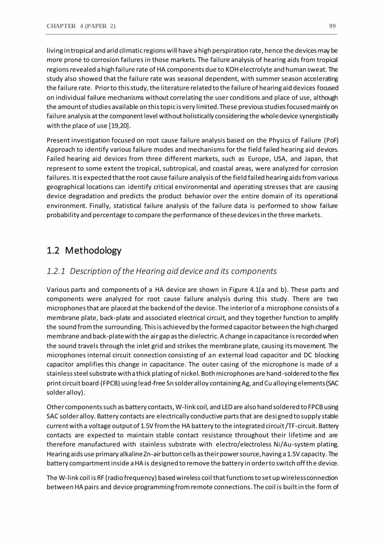
CHAPTER 4 (PAPER 2) 99
living in tropical and arid climatic regions will have a high perspiration rate, hence the devices may be
more prone to corrosion failures in those markets. The failure analysis of hearing aids from tropical
regions revealed a high failure rate of HA components due to KOH electrolyte and human sweat. The
study also showed that the failure rate was seasonal dependent, with summer season accelerating
the failure rate. Prior to this study, the literature related to the failure of hearing aid devices focused
on individual failure mechanisms without correlating the user conditions and place of use, although
the amount of studies available on this topic is very limited. These previous studies focused mainly on
failure analysis at the component level without holistically considering the whole device synergistically
with the place of use [19,20].
Present investigation focused on root cause failure analysis based on the Physics of Failure (PoF)
Approach to identify various failure modes and mechanisms for the field failed hearing aid devices.
Failed hearing aid devices from three different markets, such as Europe, USA, and Japan, that
represent to some extent the tropical, subtropical, and coastal areas, were analyzed for corrosion
failures. It is expected that the root cause failure analysis of the field failed hearing aids from various
geographical locations can identify critical environmental and operating stresses that are causing
device degradation and predicts the product behavior over the entire domain of its operational
environment. Finally, statistical failure analysis of the failure data is performed to show failure
probability and percentage to compare the performance of these devices in the three markets.
1.2 Methodology
1.2.1 Description of the Hearing aid device and its components
Various parts and components of a HA device are shown in Figure 4.1(a and b). These parts and
components were analyzed for root cause failure analysis during this study. There are two
microphones that are placed at the backend of the device. The interior of a microphone consists of a
membrane plate, back-plate and associated electrical circuit, and they together function to amplify
the sound from the surrounding. This is achieved by the formed capacitor between the high charged
membrane and back-plate with the air gap as the dielectric. A change in capacitance is recorded when
the sound travels through the inlet grid and strikes the membrane plate, causing its movement. The
microphones internal circuit connection consisting of an external load capacitor and DC blocking
capacitor amplifies this change in capacitance. The outer casing of the microphone is made of a
stainless steel substrate with a thick plating of nickel. Both microphones are hand-soldered to the flex
print circuit board (FPCB) using lead-free Sn solder alloy containing Ag, and Cu alloying elements (SAC
solder alloy).
Other components such as battery contacts, W-link coil, and LED are also hand soldered to FPCB using
SAC solder alloy. Battery contacts are electrically conductive parts that are desi gned to supply stable
current with a voltage output of 1.5V from the HA battery to the integrated circuit /TF-circuit. Battery
contacts are expected to maintain stable contact resistance throughout their lifetime and are
therefore manufactured with stainless substrate with electro/electroless Ni/Au-system plating.
Hearing aids use primary alkaline Zn-air button cells as their power source, having a 1.5V capacity. The
battery compartment inside a HA is designed to remove the battery in order to switch off the device.
The W-link coil is RF (radio frequency) based wireless coil that functions to set up wireless connection
between HA pairs and device programming from remote connections. The coil is built in the form of
A COMPARITIVE STUDY ON CORROSION FAILURE ANALYSIS OF
HEARING AID DEVICES FROM DIFFERENT MARKETS 100
copper wire windings, which are coated with polymer lacquer to protect it from moisture and
corrosion. There are three microswitches for volume and program control that are surface mounted
on the FPCB. They are tactile-based switches consisting of a separate silver-plated steel push button
and three silver pads molded in plastic. They function with a touch that pushes the dome to make
contact with the silver pads, completing the electric circuit. The switch housing is protected with a
laser-welded Teflon cover, which seals the switch and prevents any kind of electrolyte or moisture
from accessing the interior metal parts.
The Thick film circuit (TF-circuit) component is considered as the engine of the HA device, whose
function is to perform sound signal processing and other electronic functions of the device. It consists
of various IC chips, and other surface mounted electronic components. The components are mounted
on the TF substrate by reflow soldering process using SAC solder alloy, and the entire TF circuit is
surface mounted on the FPCB. All the components of the HA device are mounted on a plastic block
and is covered with a plastic casing to cover the interior of the device. These plastic casings are coated
with hydrophobic nanocoating to prevent any liquid intrusion.
The conformal coatings are applied to various components in order to protect them from corrosion.
Hand solderings are protected using fluorinated acrylate-based polymer coating, whereas the TF
circuit is protected with silicone-based coating. The three tact switches are underfi lled with hard
epoxy. The protection at hand solderings, and TF-circuit are marked as red and yellow areas in Figure
4.1(b), respectively.
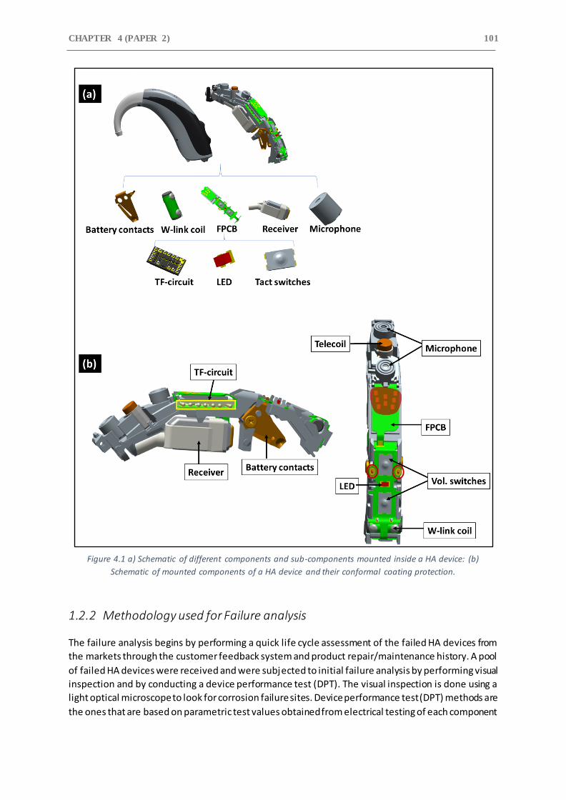
CHAPTER 4 (PAPER 2) 101
Figure 4.1 a) Schematic of different components and sub-components mounted inside a HA device: (b)
Schematic of mounted components of a HA device and their conformal coating protection.
1.2.2 Methodology used for Failure analysis
The failure analysis begins by performing a quick life cycle assessment of the failed HA devices from
the markets through the customer feedback system and product repair/maintenance history. A pool
of failed HA devices were received and were subjected to initial failure analysis by performing visual
inspection and by conducting a device performance test (DPT). The visual inspection is done using a
light optical microscope to look for corrosion failure sites. Device performance test (DPT) methods are
the ones that are based on parametric test values obtained from electrical testing of each component
A COMPARITIVE STUDY ON CORROSION FAILURE ANALYSIS OF
HEARING AID DEVICES FROM DIFFERENT MARKETS 102
or sub-component of the device. These parametric test values are fed as input to a computer model
to identify parameters that result in low performance. From the pool of failed devices, 30 HA’s from
each market (Europe, USA, & Japan) were picked as corrosion failed devices for detailed root cause
failure analysis. Some of the criteria to filter corrosion-induced failures were: i) high current
consumption, ii) visual observation of corrosion products inside the device, and iii) very low
performance of device microphones from DPT.
The following step is identifying different parts and components of the device to be analyzed based
on the results from the device performance test and initial visual inspection of the device parts and
subparts. Failure analysis is performed at the identified failure site to reveal the failure mechanism for
that particular component of the device. The failure analysis was carried out using a scanning electron
microscope (SEM) equipped with energy-dispersive X-ray spectroscopy (EDS) to investigate the
corrosion product morphology and chemical composition. Instrument type Quanta FEG ESEM with
Oxford X-max EDS capability was used for microscopy analysis. Along with showing the morphology,
the low-resolution SEM images of the failure sites can determine the cause and effect of the corrosion
by finding the type of corrosion process. Different components and sub-components of the field failed
devices were dismantled carefully and mounted on aluminum stub using carbon tape for SEM analysis.
The next step in the failure analysis process is performing a statistical failure analysis of the data from
life cycle assessment and root cause failure analysis to reveal percentage distribution of failed
components, failure probability, and risk to failure probability for failed HA’s components from each
market. Failure statistics is performed by creating a list of categories such as product ID, failure areas,
failure type, and device operational period (the duration that the device was operational in the field).
Pie charts, histograms, and line charts from pivot tables (MS-Excel) were used to visually summarize
and conclude on the identified failure parts of HA’s, failure probability and percentage for different
device components, and types of contamination present inside the device. The failure statistics were
compared for the three markets to reveal the performance of hearing aid devices across different
geographical locations.
1.3 Result and discussion
1.3.1 Failure analysis
Root cause failure analysis was carried out on 30 field failed HA devices from each market i.e
European, Japan, and the USA. These 30 devices were particularly picked from the pool of faulty
devices as corrosion failed based on their visual inspection and DPT test. The root cause failure analysis
was carried out using a scanning electron microscope (SEM) equipped with EDS capability. Different
components of a HA were analyzed, and their failure mechanisms and causes are discussed based on
microscopy analysis. Similarly, chemical analysis of corrosion products were able to reveal the type of
corrosive species involved in the corrosion failure of components, and their potential sources are
discussed. Components failure mechanisms are discussed by taking specific failure cases from
individual markets that are representative of similar failures found in other failed devices.
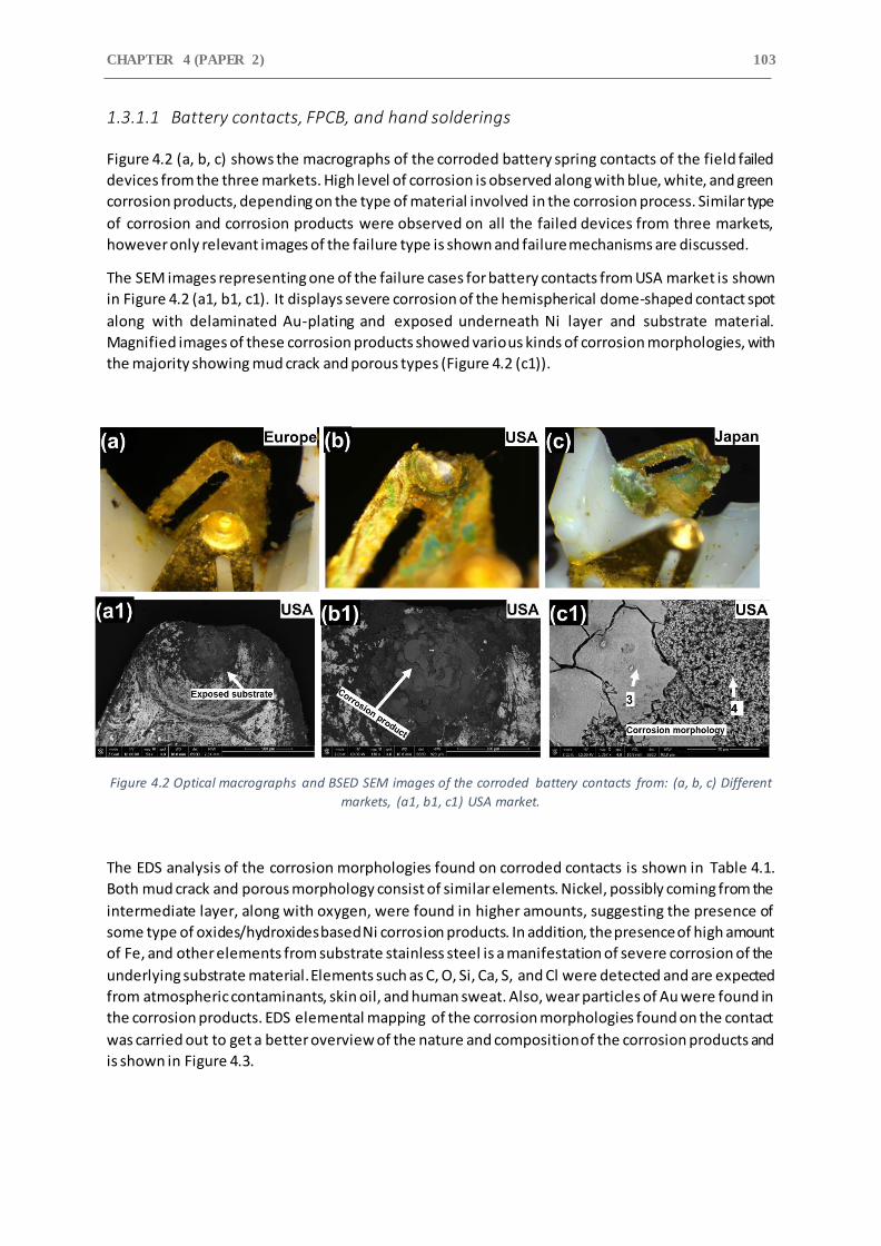
CHAPTER 4 (PAPER 2) 103
1.3.1.1 Battery contacts, FPCB, and hand solderings
Figure 4.2 (a, b, c) shows the macrographs of the corroded battery spring contacts of the field failed
devices from the three markets. High level of corrosion is observed along with blue, white, and green
corrosion products, depending on the type of material involved in the corrosion process. Similar type
of corrosion and corrosion products were observed on all the failed devices from three markets,
however only relevant images of the failure type is shown and failure mechanisms are discussed.
The SEM images representing one of the failure cases for battery contacts from USA market is shown
in Figure 4.2 (a1, b1, c1). It displays severe corrosion of the hemispherical dome-shaped contact spot
along with delaminated Au-plating and exposed underneath Ni layer and substrate material.
Magnified images of these corrosion products showed various kinds of corrosion morphologies, with
the majority showing mud crack and porous types (Figure 4.2 (c1)).
Figure 4.2 Optical macrographs and BSED SEM images of the corroded battery contacts from: (a, b, c) Different
markets, (a1, b1, c1) USA market.
The EDS analysis of the corrosion morphologies found on corroded contacts is shown in Table 4.1.
Both mud crack and porous morphology consist of similar elements. Nickel, possibly coming from the
intermediate layer, along with oxygen, were found in higher amounts, suggesting the presence of
some type of oxides/hydroxides based Ni corrosion products. In addition, the presence of high amount
of Fe, and other elements from substrate stainless steel is a manifestation of severe corrosion of the
underlying substrate material. Elements such as C, O, Si, Ca, S, and Cl were detected and are expected
from atmospheric contaminants, skin oil, and human sweat. Also, wear particles of Au were found in
the corrosion products. EDS elemental mapping of the corrosion morphologies found on the contact
was carried out to get a better overview of the nature and composition of the corrosion products and
is shown in Figure 4.3.
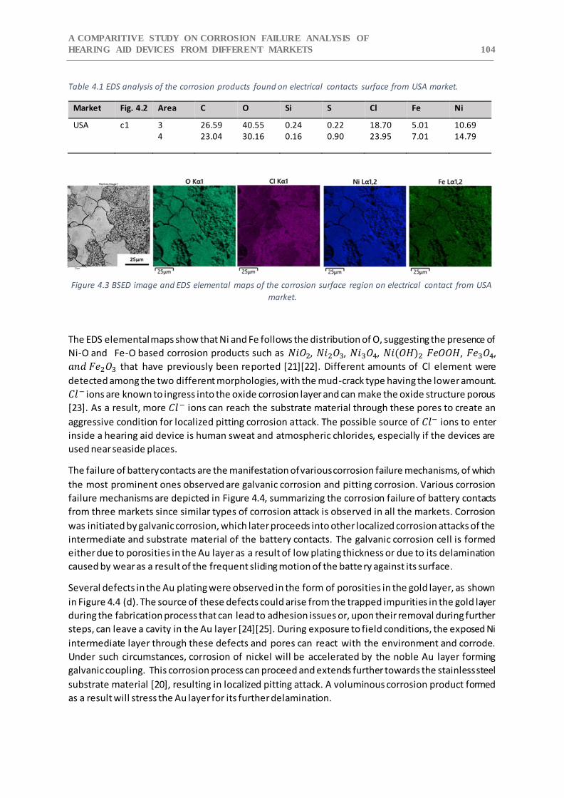
A COMPARITIVE STUDY ON CORROSION FAILURE ANALYSIS OF
HEARING AID DEVICES FROM DIFFERENT MARKETS 104
Table 4.1 EDS analysis of the corrosion products found on electrical contacts surface from USA market.
Market Fig. 4.2 Area C O Si S Cl Fe Ni
USA c1 3 26.59 40.55 0.24 0.22 18.70 5.01 10.69 4 23.04 30.16 0.16 0.90 23.95 7.01 14.79
Figure 4.3 BSED image and EDS elemental maps of the corrosion surface region on electrical contact from USA
market.
The EDS elemental maps show that Ni and Fe follows the distribution of O, suggesting the presence of
Ni-O and Fe-O based corrosion products such as 𝑁𝑖𝑂2, 𝑁𝑖2𝑂3, 𝑁𝑖3𝑂4, 𝑁𝑖(𝑂𝐻)2 𝐹𝑒𝑂𝑂𝐻, 𝐹𝑒3𝑂4,
𝑎𝑛𝑑 𝐹𝑒2𝑂3 that have previously been reported [21][22]. Different amounts of Cl element were
detected among the two different morphologies, with the mud-crack type having the lower amount.
𝐶𝑙− ions are known to ingress into the oxide corrosion layer and can make the oxide structure porous
[23]. As a result, more 𝐶𝑙− ions can reach the substrate material through these pores to create an
aggressive condition for localized pitting corrosion attack. The possible source of 𝐶𝑙− ions to enter
inside a hearing aid device is human sweat and atmospheric chlorides, especially if the devices are
used near seaside places.
The failure of battery contacts are the manifestation of various corrosion failure mechanisms, of which
the most prominent ones observed are galvanic corrosion and pitting corrosion. Various corrosion
failure mechanisms are depicted in Figure 4.4, summarizing the corrosion failure of battery contacts
from three markets since similar types of corrosion attack is observed in all the markets. Corrosion
was initiated by galvanic corrosion, which later proceeds into other localized corrosion attacks of the
intermediate and substrate material of the battery contacts. The galvanic corrosion cell is formed
either due to porosities in the Au layer as a result of low plating thickness or due to its delamination
caused by wear as a result of the frequent sliding motion of the battery against its surface.
Several defects in the Au plating were observed in the form of porosities in the gold layer, as shown
in Figure 4.4 (d). The source of these defects could arise from the trapped impurities in the gold layer
during the fabrication process that can lead to adhesion issues or, upon their removal during further
steps, can leave a cavity in the Au layer [24][25]. During exposure to field conditions, the exposed Ni
intermediate layer through these defects and pores can react with the environment and corrode.
Under such circumstances, corrosion of nickel will be accelerated by the noble Au layer forming
galvanic coupling. This corrosion process can proceed and extends further towards the stainless steel
substrate material [20], resulting in localized pitting attack. A voluminous corrosion product formed
as a result will stress the Au layer for its further delamination.
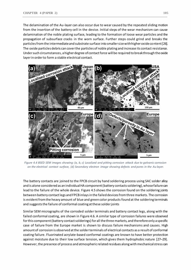
CHAPTER 4 (PAPER 2) 105
The delamination of the Au-layer can also occur due to wear caused by the repeated sliding motion
from the insertion of the battery cell in the device. Initial steps of the wear mechanism can cause
delamination of the noble plating surface, leading to the formation of loose wear particles and the
propagation of subsurface cracks in the worn surface. Further steps could grind and breaks the
particles from the intermediate and substrate surface into smaller size with higher oxide content [26].
The oxide particles debris can cover the particles of noble plating and increase its contact resistance.
Under such circumstances, a higher degree of contact force will be required to break through the oxide
layer in order to form a stable electrical contact.
Figure 4.4 BSED SEM images showing: (a, b, c) Localized and pitting corrosion attack due to galvanic corrosion
on the electrical contact surface, (d) Secondary electron image showing defects and pores in the Au layer.
The battery contacts are joined to the FPCB circuit by hand soldering process using SAC solder alloy
and is alone considered as an individual HA component (battery contacts soldering), whose failure can
lead to the failure of the whole device. Figure 4.5 shows the corrosion found on the soldering joints
between battery contact legs and FPCB inlays in the failed devices from three markets. The corrosion
is evident from the heavy amount of blue and green color products found at the soldering terminals
and suggests the failure of conformal coating at these solder joints
Similar SEM micrographs of the corroded solder terminals and battery contact legs, along with the
failed conformal coating, are shown in Figure 4.6. A similar type of corrosion failures were observed
for this component (battery contact solderings) for all the three markets, and therefore only a specific
case of failure from the Europe market is shown to discuss failure mechanisms and causes. High
amount of corrosion is observed at the solder terminals of electrical contacts as a result of conformal
coating failure. Fluorinated acrylate-based conformal coatings are known to have better protection
against moisture due to their low surface tension, which gives them hydrophobic nature [27–29].
However, the presence of process and atmospheric related residues along with mechanical stress can
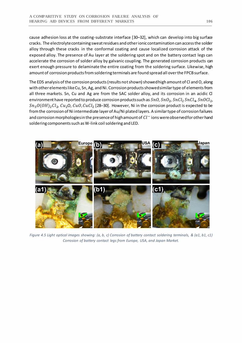
A COMPARITIVE STUDY ON CORROSION FAILURE ANALYSIS OF
HEARING AID DEVICES FROM DIFFERENT MARKETS 106
cause adhesion loss at the coating-substrate interface [30–32], which can develop into big surface
cracks. The electrolyte containing sweat residues and other ionic contamination can access the solder
alloy through these cracks in the conformal coating and cause localized corrosion attack of the
exposed alloy. The presence of Au layer at the soldering spot and on the battery contact legs can
accelerate the corrosion of solder alloy by galvanic coupling. The generated corrosion products can
exert enough pressure to delaminate the entire coating from the soldering surface. Likewise, high
amount of corrosion products from soldering terminals are found spread all over the FPCB surface.
The EDS analysis of the corrosion products (results not shown) showed high amount of Cl and O, along
with other elements like Cu, Sn, Ag, and Ni. Corrosion products showed similar type of elements from
all three markets. Sn, Cu and Ag are from the SAC solder alloy, and its corrosion in an acidic Cl
environment have reported to produce corrosion products such as 𝑆𝑛𝑂, 𝑆𝑛𝑂2, 𝑆𝑛𝐶𝑙2 𝑆𝑛𝐶𝑙4, 𝑆𝑛𝑂𝐶𝑙2,
𝑆𝑛3𝑂(𝑂𝐻)2𝐶𝑙2, 𝐶𝑢2O, 𝐶𝑢𝑂, 𝐶𝑢𝐶𝑙2 [28–30]. However, Ni in the corrosion product is expected to be
from the corrosion of Ni intermediate layer of Au/Ni plated layers. A similar type of corrosion failures
and corrosion morphologies in the presence of high amount of 𝐶𝑙− ions were observed for other hand
soldering components such as W-link coil soldering and LED.
Figure 4.5 Light optical images showing: (a, b, c) Corrosion of battery contact soldering terminals, & (a1, b1, c1)
Corrosion of battery contact legs from Europe, USA, and Japan Market.
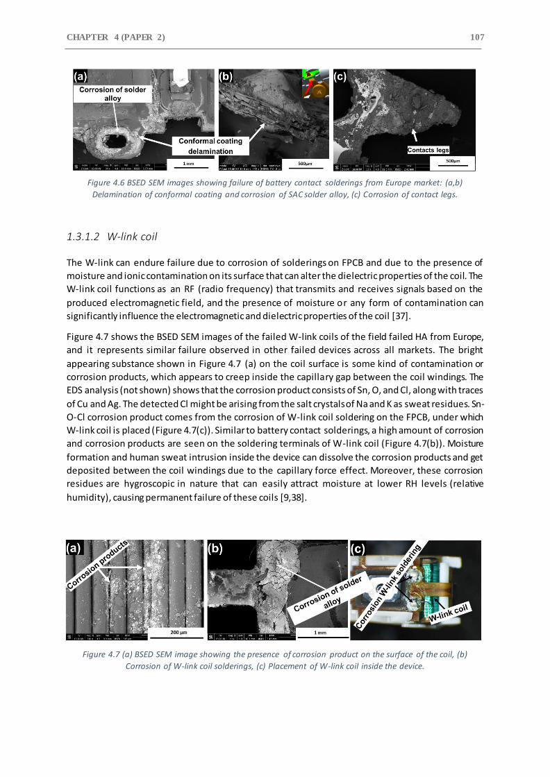
CHAPTER 4 (PAPER 2) 107
Figure 4.6 BSED SEM images showing failure of battery contact solderings from Europe market: (a,b)
Delamination of conformal coating and corrosion of SAC solder alloy, (c) Corrosion of contact legs.
1.3.1.2 W-link coil
The W-link can endure failure due to corrosion of solderings on FPCB and due to the presence of
moisture and ionic contamination on its surface that can alter the dielectric properties of the coil. The
W-link coil functions as an RF (radio frequency) that transmits and receives signals based on the
produced electromagnetic field, and the presence of moisture or any form of contamination can
significantly influence the electromagnetic and dielectric properties of the coil [37].
Figure 4.7 shows the BSED SEM images of the failed W-link coils of the field failed HA from Europe,
and it represents similar failure observed in other failed devices across all markets. The bright
appearing substance shown in Figure 4.7 (a) on the coil surface is some kind of contamination or
corrosion products, which appears to creep inside the capillary gap between the coil windings. The
EDS analysis (not shown) shows that the corrosion product consists of Sn, O, and Cl, along with traces
of Cu and Ag. The detected Cl might be arising from the salt crystals of Na and K as sweat residues. Sn-
O-Cl corrosion product comes from the corrosion of W-link coil soldering on the FPCB, under which
W-link coil is placed (Figure 4.7(c)). Similar to battery contact solderings, a high amount of corrosion
and corrosion products are seen on the soldering terminals of W-link coil (Figure 4.7(b)). Moisture
formation and human sweat intrusion inside the device can dissolve the corrosion products and get
deposited between the coil windings due to the capillary force effect. Moreover, these corrosion
residues are hygroscopic in nature that can easily attract moisture at lower RH levels (relative
humidity), causing permanent failure of these coils [9,38].
Figure 4.7 (a) BSED SEM image showing the presence of corrosion product on the surface of the coil, (b)
Corrosion of W-link coil solderings, (c) Placement of W-link coil inside the device.

A COMPARITIVE STUDY ON CORROSION FAILURE ANALYSIS OF
HEARING AID DEVICES FROM DIFFERENT MARKETS 108
1.3.1.3 Volume and Program Switches
Figure 4.8 shows the images of the failed switches from different markets. A high amount of human
secreted sebum (brown greasy substance present inside of the ear) was found on the Teflon cover of
the switches and around it. Human sebum is secreted from the skin and consists of free fatty acids,
triglycerides, wax esters, squalene, sodium chloride, and some amount of cholesterol [39]. It is a very
sticky substance and can easily enter the HA device due to its direct contact with human skin. The
effect of human sebum on the failure of switches is illustrated through macrographs shown in Figure
4.8. It shows delamination of the Teflon switch cover, which can allow moisture, sebum, and corrosion
electrolyte to enter inside the switch, causing corrosion degradation or deposition of contamination
on the surface of the silver-plated contact pads. Likewise, its soldering terminals were found corroded
in the presence of sebum and other corrosive ions.
The SEM micrographs of the interior of the corrosion failed switch from USA market is shown in Figure
4.9. These contaminants seem to have covered the entire surface of the contact junction (contact
between the dome and contact pads), which can lead to an increase in their contact resistance and
thus cause no functional response from the use of the switch. High amount of C element was detected
during EDS analysis (not shown) of the electrical pads that confirm the presence of organic
contaminants such as sebum. The presence of other elements such as Ag, Na, K, and Cl suggest the
corrosion of these electrical pads occurred in the presence of chloride-based salts of Na and K.
Extreme corroded areas showing elements like Fe, Cr, and Ni suggest corrosion might have penetrated
under the Ag plating into the substrate stainless material.
Figure 4.8 Light optical images of the field failed switches from different markets.
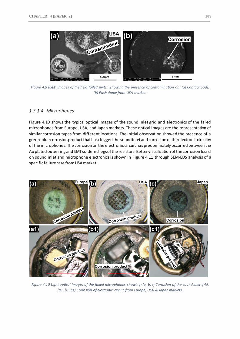
CHAPTER 4 (PAPER 2) 109
Figure 4.9 BSED images of the field failed switch showing the presence of contamination on: (a) Contact pads,
(b) Push dome from USA market.
1.3.1.4 Microphones
Figure 4.10 shows the typical optical images of the sound inlet grid and electronics of the failed
microphones from Europe, USA, and Japan markets. These optical images are the representation of
similar corrosion types from different locations. The initial observation showed the presence of a
green-blue corrosion product that has clogged the sound inlet and corrosion of the electronic circuitry
of the microphones. The corrosion on the electronic circuit has predominately occurred between the
Au plated outer ring and SMT soldered legs of the resistors. Better visualization of the corrosion found
on sound inlet and microphone electronics is shown in Figure 4.11 through SEM-EDS analysis of a
specific failure case from USA market.
Figure 4.10 Light optical images of the failed microphones showing: (a, b, c) Corrosion of the sound inlet grid,
(a1, b1, c1) Corrosion of electronic circuit from Europe, USA & Japan markets.
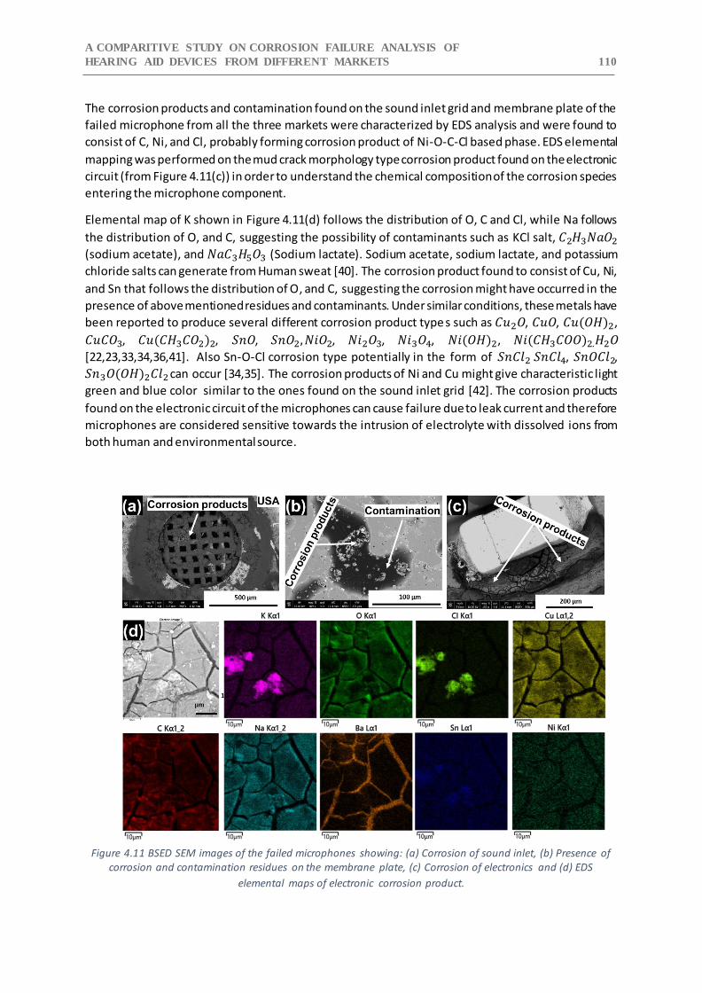
A COMPARITIVE STUDY ON CORROSION FAILURE ANALYSIS OF
HEARING AID DEVICES FROM DIFFERENT MARKETS 110
The corrosion products and contamination found on the sound inlet grid and membrane plate of the
failed microphone from all the three markets were characterized by EDS analysis and were found to
consist of C, Ni, and Cl, probably forming corrosion product of Ni-O-C-Cl based phase. EDS elemental
mapping was performed on the mud crack morphology type corrosion product found on the electronic
circuit (from Figure 4.11(c)) in order to understand the chemical composition of the corrosion species
entering the microphone component.
Elemental map of K shown in Figure 4.11(d) follows the distribution of O, C and Cl, while Na follows
the distribution of O, and C, suggesting the possibility of contaminants such as KCl salt, 𝐶2𝐻3𝑁𝑎𝑂2
(sodium acetate), and 𝑁𝑎𝐶3𝐻5𝑂3 (Sodium lactate). Sodium acetate, sodium lactate, and potassium
chloride salts can generate from Human sweat [40]. The corrosion product found to consist of Cu, Ni,
and Sn that follows the distribution of O, and C, suggesting the corrosion might have occurred in the
presence of above mentioned residues and contaminants. Under similar conditions, these metals have
been reported to produce several different corrosion product type s such as 𝐶𝑢2𝑂, 𝐶𝑢𝑂, 𝐶𝑢(𝑂𝐻)2,
𝐶𝑢𝐶𝑂3, 𝐶𝑢(𝐶𝐻3𝐶𝑂2)2, 𝑆𝑛𝑂, 𝑆𝑛𝑂2, 𝑁𝑖𝑂2, 𝑁𝑖2𝑂3, 𝑁𝑖3𝑂4, 𝑁𝑖(𝑂𝐻)2, 𝑁𝑖(𝐶𝐻3𝐶𝑂𝑂)2.𝐻2𝑂
[22,23,33,34,36,41]. Also Sn-O-Cl corrosion type potentially in the form of 𝑆𝑛𝐶𝑙2 𝑆𝑛𝐶𝑙4, 𝑆𝑛𝑂𝐶𝑙2,
𝑆𝑛3𝑂(𝑂𝐻)2𝐶𝑙2 can occur [34,35]. The corrosion products of Ni and Cu might give characteristic light
green and blue color similar to the ones found on the sound inlet grid [42]. The corrosion products
found on the electronic circuit of the microphones can cause failure due to leak current and therefore
microphones are considered sensitive towards the intrusion of electrolyte with dissolved ions from
both human and environmental source.
Figure 4.11 BSED SEM images of the failed microphones showing: (a) Corrosion of sound inlet, (b) Presence of
corrosion and contamination residues on the membrane plate, (c) Corrosion of electronics and (d) EDS
elemental maps of electronic corrosion product.
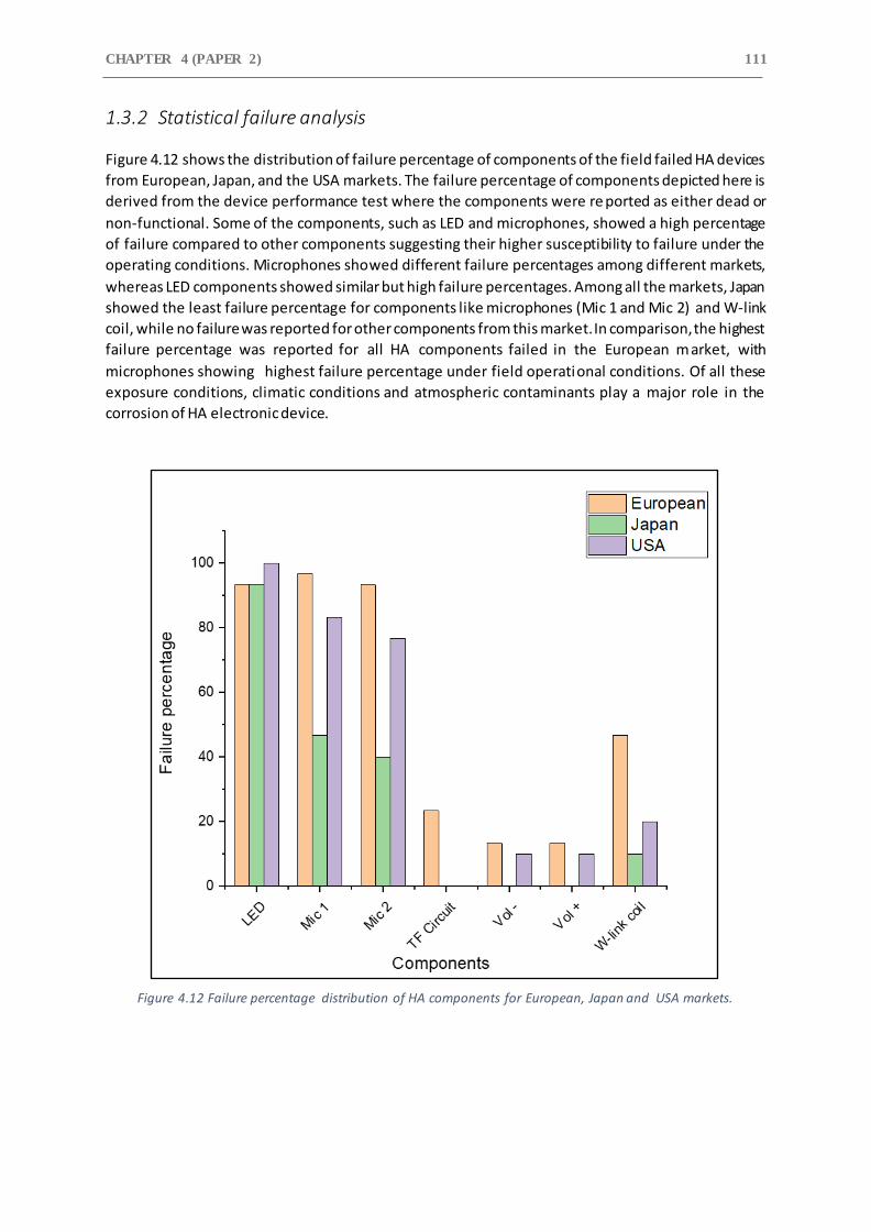
CHAPTER 4 (PAPER 2) 111
1.3.2 Statistical failure analysis
Figure 4.12 shows the distribution of failure percentage of components of the field failed HA devices
from European, Japan, and the USA markets. The failure percentage of components depicted here is
derived from the device performance test where the components were re ported as either dead or
non-functional. Some of the components, such as LED and microphones, showed a high percentage
of failure compared to other components suggesting their higher susceptibility to failure under the
operating conditions. Microphones showed different failure percentages among different markets,
whereas LED components showed similar but high failure percentages. Among all the markets, Japan
showed the least failure percentage for components like microphones (Mic 1 and Mic 2) and W-link
coil, while no failure was reported for other components from this market. In comparison, the highest
failure percentage was reported for all HA components failed in the European market, with
microphones showing highest failure percentage under field operational conditions. Of all these
exposure conditions, climatic conditions and atmospheric contaminants play a major role in the
corrosion of HA electronic device.
Figure 4.12 Failure percentage distribution of HA components for European, Japan and USA markets.
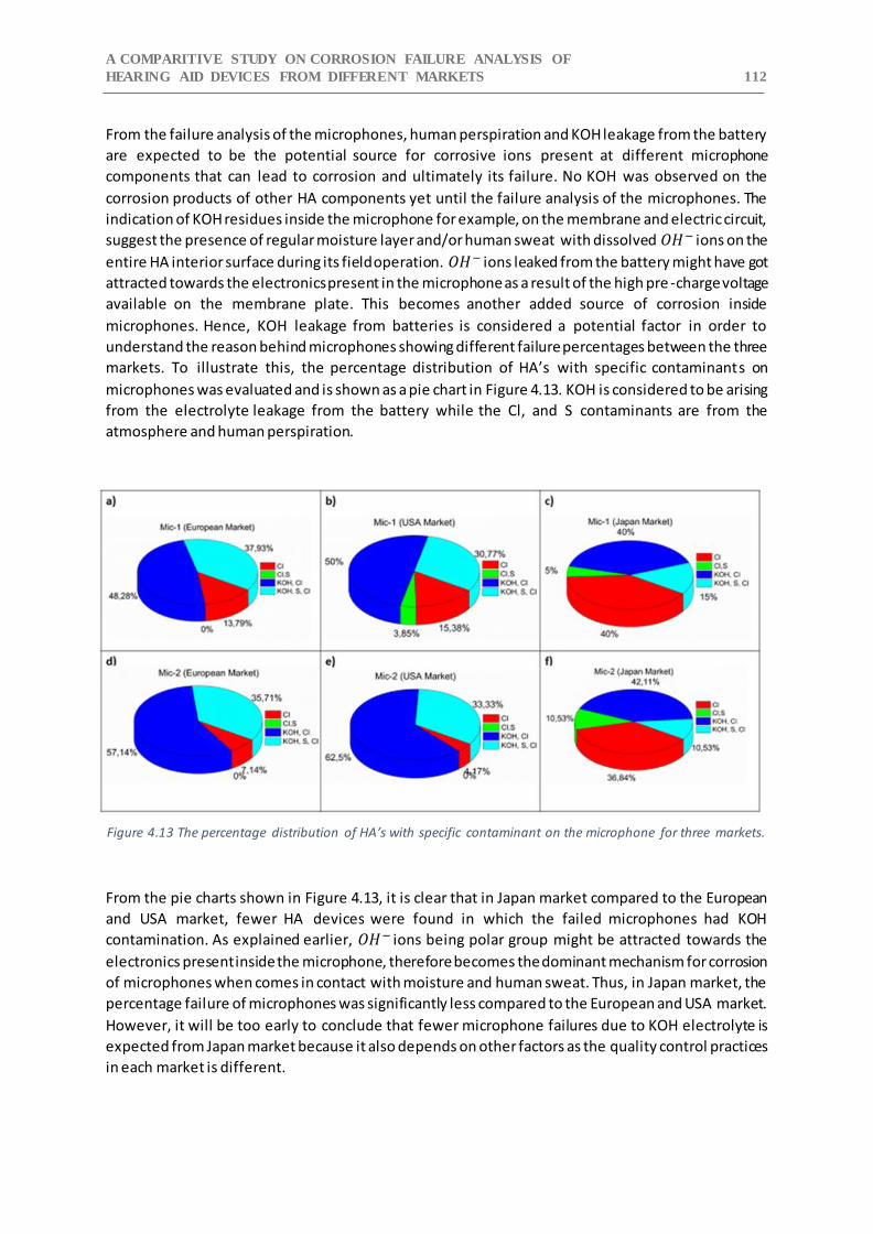
A COMPARITIVE STUDY ON CORROSION FAILURE ANALYSIS OF
HEARING AID DEVICES FROM DIFFERENT MARKETS 112
From the failure analysis of the microphones, human perspiration and KOH leakage from the battery
are expected to be the potential source for corrosive ions present at different microphone
components that can lead to corrosion and ultimately its failure. No KOH was observed on the
corrosion products of other HA components yet until the failure analysis of the microphones. The
indication of KOH residues inside the microphone for example, on the membrane and electric circuit,
suggest the presence of regular moisture layer and/or human sweat with dissolved 𝑂𝐻− ions on the
entire HA interior surface during its field operation. 𝑂𝐻− ions leaked from the battery might have got
attracted towards the electronics present in the microphone as a result of the high pre -charge voltage
available on the membrane plate. This becomes another added source of corrosion inside
microphones. Hence, KOH leakage from batteries is considered a potential factor in order to
understand the reason behind microphones showing different failure percentages between the three
markets. To illustrate this, the percentage distribution of HA’s with specific contaminants on
microphones was evaluated and is shown as a pie chart in Figure 4.13. KOH is considered to be arising
from the electrolyte leakage from the battery while the Cl, and S contaminants are from the
atmosphere and human perspiration.
Figure 4.13 The percentage distribution of HA’s with specific contaminant on the microphone for three markets.
From the pie charts shown in Figure 4.13, it is clear that in Japan market compared to the European
and USA market, fewer HA devices were found in which the failed microphones had KOH
contamination. As explained earlier, 𝑂𝐻− ions being polar group might be attracted towards the
electronics present inside the microphone, therefore becomes the dominant mechanism for corrosion
of microphones when comes in contact with moisture and human sweat. Thus, in Japan market, the
percentage failure of microphones was significantly less compared to the European and USA market.
However, it will be too early to conclude that fewer microphone failures due to KOH electrolyte is
expected from Japan market because it also depends on other factors as the quality control practices
in each market is different.
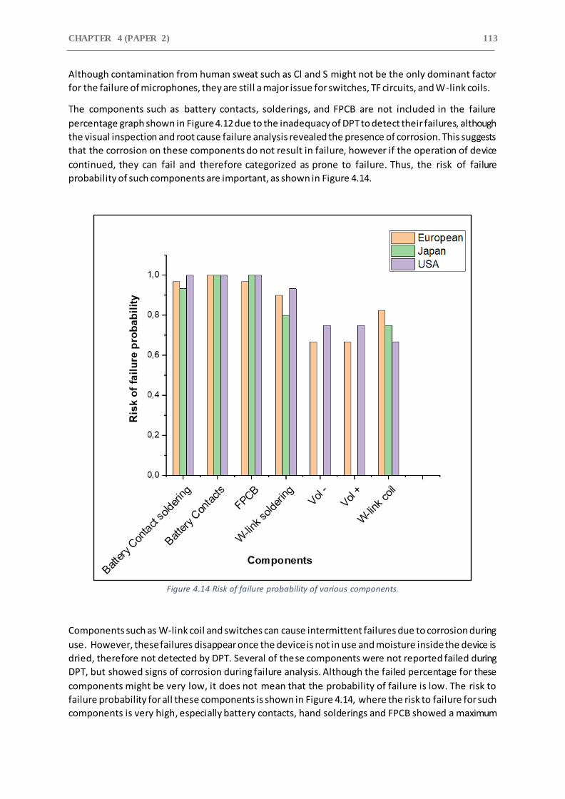
CHAPTER 4 (PAPER 2) 113
Although contamination from human sweat such as Cl and S might not be the only dominant factor
for the failure of microphones, they are still a major issue for switches, TF circuits, and W-link coils.
The components such as battery contacts, solderings, and FPCB are not included in the failure
percentage graph shown in Figure 4.12 due to the inadequacy of DPT to detect their failures, although
the visual inspection and root cause failure analysis revealed the presence of corrosion. This suggests
that the corrosion on these components do not result in failure, however if the operation of device
continued, they can fail and therefore categorized as prone to failure. Thus, the risk of failure
probability of such components are important, as shown in Figure 4.14.
Figure 4.14 Risk of failure probability of various components.
Components such as W-link coil and switches can cause intermittent failures due to corrosion during
use. However, these failures disappear once the device is not in use and moisture inside the device is
dried, therefore not detected by DPT. Several of these components were not reported failed during
DPT, but showed signs of corrosion during failure analysis. Although the failed percentage for these
components might be very low, it does not mean that the probability of failure is low. The risk to
failure probability for all these components is shown in Figure 4.14, where the risk to failure for such
components is very high, especially battery contacts, hand solderings and FPCB showed a maximum

A COMPARITIVE STUDY ON CORROSION FAILURE ANALYSIS OF
HEARING AID DEVICES FROM DIFFERENT MARKETS 114
failure probability of 1. The risk to failure probability for these components is calculated by summation
of the number of components in the failed and prone category. The failed components were reported
non-functional after the device performance test, whereas prone to failure components did not show
any functionality issues but showed a significant level of corrosion during SEM-EDS analysis.
1.4 Conclusion
Corrosion failure analysis of field failed hearing aid devices from three different geographical locations
i.e. Europe, USA, & Japan was performed. Different corrosion failure mechanisms were found for
various hearing aid parts and components. The study provided the following key conclusions:
High level of corrosion was observed on battery contacts, contact soldering terminals, LED,
and W-link coil soldering with similar high risk to failure probability for all three markets.
Galvanic corrosion and failure of the conformal coating were the dominant failure
mechanisms observed.
High failure percentage of microphones was observed for European and USA market
compared to Japan market. This is due to the high amount of KOH electrolyte found inside the
microphones from the European and USA market. Factors such as harsh environmental
conditions in these markets causing increased leakage of KOH electrolyte might have
attributed to this behavior.
KOH electrolyte was only found inside the failed microphones. This mi ght be due to the
movement of 𝑂𝐻− ions into the microphones due to the presence of high pre-charge voltage
on its membrane plate.
High amount of sweat residues, potentially in the form of sodium chloride, potassium chloride,
sodium acetate, and sodium lactate, were found inside the device and at the location of the
corrosion site. Some atmospheric contaminants such as silicates, salts, and sulfur were found
at the corrosion failure site as well. These dissolved contaminants in the sweat and the
moisture layer were able to cause severe corrosion failures to the hearing aid device and its
components.
1.5 Acknowledgment
This research reported here was conducted as a part of the Industrial PhD project, and the authors
would like to acknowledge the funding and help received from Innovation Fund Denmark.
CHAPTER 4 (PAPER 2) 115
References
[1] M. Tencer, J.S. Moss, Humidity management of outdoor electronic equipment: Methods, pitfalls, and recommendations, IEEE Trans. Components Packag. Technol. 25 (2002) 66–72. https://doi.org/10.1109/6144.991177.
[2] R. Ambat, S.G. Jensen, P. Moller, Corrosion Reliability of Electronic Systems, in: ECS Trans., 2008: pp. 17–28. https://doi.org/10.1149/1.2900650.
[3] E.H. Wong, S.W. Koh, K.H. Lee, R. Rajoo, Comprehensive treatment of moisture induced failure - Recent advances, IEEE Trans. Electron. Packag. Manuf. 25 (2002) 223–230. https://doi.org/10.1109/TEPM.2002.804613.
[4] H. Conseil, V. Verdingovas, M.S. Jellesen, R. Ambat, Decomposition of no-clean solder flux systems and their effects on the corrosion reliability of electronics, J. Mater. Sci. Mater. Electron. (2016). https://doi.org/10.1007/s10854-015-3712-x.
[5] V. Verdingovas, M.S. Jellesen, R. Ambat, Relative effect of solder flux chemistry on the humidity related failures in electronics, Solder. Surf. Mt. Technol. (2015). https://doi.org/10.1108/SSMT-11-2014-0022.
[6] K. Piotrowska, V. Verdingovas, M.S. Jellesen, R. Ambat, Contamination, potential bias and humidity effects on electrical performance and corrosion reliability of electronic devices, in: Eur. Corros. Congr. EUROCORR 2015, 2015.
[7] O. Thomas, M. Wickham, C. Hunt, Obtaining the moisture content of printed circuit boards from capacitance measurements, Circuit World. 38 (2012) 68–74. https://doi.org/10.1108/03056121211222282.
[8] M.G. Pecht, H. Ardebili, A.A. Shukla, J.K. Hagge, D. Jennings, Moisture ingress into organic laminates, IEEE Trans. Components Packag. Technol. 22 (1999) 104–110. https://doi.org/10.1109/6144.759359.
[9] H. Conseil, M.S. Jellesen, R. Ambat, Experimental study of water absorption of electronic components and internal local temperature and humidity into electronic enclosure, Electron. Packag. Technol. Conf. (EPTC), 2014 IEEE 16th. (2014) 355–359. https://doi.org/10.1109/EPTC.2014.7028356.
[10] V. Verdingovas, M.S. Jellesen, R. Ambat, Impact of NaCl contamination and climatic conditions on the reliability of printed circuit board assemblies, IEEE Trans. Device Mater. Reliab. (2014). https://doi.org/10.1109/TDMR.2013.2293792.
[11] Ipc-Hdbk-830, Guidelines for Design, Selection and Application of Conformal Coatings, 2013.
[12] H. Conseil-Gudla, Z. Staliulionis, S. Mohanty, M.S. Jellesen, J.H. Hattel, R. Ambat, Humidity build-up in electronic enclosures exposed to different geographical locations by RC modelling and reliability prediction, Microelectron. Reliab. 82 (2018). https://doi.org/10.1016/j.microrel.2018.01.013.
[13] H. Huang, X. Guo, G. Zhang, Z. Dong, The effects of temperature and electric field on atmospheric corrosion behaviour of PCB-Cu under absorbed thin electrolyte layer, Corros. Sci. 53 (2011). https://doi.org/10.1016/j.corsci.2011.01.031.
[14] A.A.A. Mohtar, M.T. Latif, N.H. Baharudin, F. Ahamad, J.X. Chung, M. Othman, L. Juneng, Variation of major air pollutants in different seasonal conditions in an urban environment in Malaysia, Geosci. Lett. 5 (2018). https://doi.org/10.1186/s40562-018-0122-y.
A COMPARITIVE STUDY ON CORROSION FAILURE ANALYSIS OF
HEARING AID DEVICES FROM DIFFERENT MARKETS 116
[15] W.R. Wan Mahiyuddin, M. Sahani, R. Aripin, M.T. Latif, T.Q. Thach, C.M. Wong, Short-term
effects of daily air pollution on mortality, Atmos. Environ. 65 (2013). https://doi.org/10.1016/j.atmosenv.2012.10.019.
[16] M. Morcillo, E. Almeida, M. Marrocos, B. Rosales, Atmospheric corrosion of copper in Ibero-America, Corrosion. 57 (2001). https://doi.org/10.5006/1.3290321.
[17] ISO, Corrosion of metals and alloys – Corrosivity of atmospheres – Classification, determination and estimation, ISO FDIS. 13B (2012).
[18] K. Slamova, Mapping atmospheric corrosion in coastal regions: methods and results, J. Photonics Energy. 2 (2012). https://doi.org/10.1117/1.jpe.2.022003.
[19] A. Islam, H.N. Hansen, F. Risager, P.T. Tang, Experimental investigation on corrosion properties of LDS MID for hearing aid applications, in: Annu. Tech. Conf. - ANTEC, Conf. Proc., 2014: pp. 770–774. http://www.scopus.com/inward/record.url?eid=2-s2.0-84938070409&partnerID=tZOtx3y1.
[20] V.C. Gudla, R. Ambat, Corrosion failure analysis of hearing aid battery-spring contacts, Eng. Fail. Anal. (2017). https://doi.org/10.1016/j.engfailanal.2017.05.045.
[21] Z. You, Y. Lai, H. Zeng, Y. Yang, Influence of water and sodium chloride content on corrosion behavior of cast iron in silty clay, Constr. Build. Mater. (2020). https://doi.org/10.1016/j.conbuildmat.2019.117762.
[22] G. Pavapootanont, P. Wongpanya, E. Viyanit, G. Lothongkum, Corrosion behavior of Ni steels in aerated 3.5-wt.% NaCl solution at 25oC by potentiodynamic method, Eng. J. (2018). https://doi.org/10.4186/ej.2018.22.4.1.
[23] G.A. El-Mahdy, K.B. Kim, A laboratory study on the atmospheric corrosion of nickel in NaCl solutions during cycling wet-dry conditions, Electrochemistry. (2007). https://doi.org/10.5796/electrochemistry.75.403.
[24] E. Salahinejad, R. Eslami Farsani, L. Tayebi, Synergistic galvanic-pitting corrosion of copper electrical pads treated with electroless nickel-phosphorus/immersion gold surface finish, Eng. Fail. Anal. (2017). https://doi.org/10.1016/j.engfailanal.2017.03.001.
[25] C.K. Meng, T.S. Selvamuniandy, C. Gurumurthy, Discoloration related failure mechanism and its root cause in Electroless Nickel Immersion Gold (ENIG) Pad metallurgical surface finish, in: Proc. Int. Symp. Phys. Fail. Anal. Integr. Circuits, IPFA, 2004. https://doi.org/10.1109/ipfa.2004.1345605.
[26] J. Song, C. Koch, Wear patterns and lifetime of electric contacts, in: Electr. Contacts, Proc. Annu. Holm Conf. Electr. Contacts, 2008. https://doi.org/10.1109/HOLM.2008.ECP.50.
[27] F. Yang, L. Zhu, D. Han, R. Cao, W. Li, Y. Chen, X. Wang, L. Ning, Preparation and failure behavior of fluorine-containing acrylic polyurethane coating, Prog. Org. Coatings. 90 (2016). https://doi.org/10.1016/j.porgcoat.2015.11.009.
[28] V.C. Malshe, N.S. Sangaj, Fluorinated acrylic copolymers: Part I: Study of clear coatings, Prog. Org. Coatings. 53 (2005). https://doi.org/10.1016/j.porgcoat.2005.03.003.
[29] A.F. Thünemann, A. Lieske, B.R. Paulke, Low surface energy coatings from waterborne nano-dispersions of polymer complexes, Adv. Mater. 11 (1999). https://doi.org/10.1002/(SICI)1521-4095(199903)11:4<321::AID-ADMA321>3.0.CO;2-M.
[30] U. Rathinavelu, M.S. Jellesen, R. Ambat, Effect of solder flux residue on the performance of
CHAPTER 4 (PAPER 2) 117
silicone conformal coatings on printed circuit board assemblies, Corros. Eng. Sci. Technol. (2013). https://doi.org/10.1179/1743278213Y.0000000096.
[31] S. Zhan, M.H. Azarian, M.G. Pecht, Surface insulation resistance of conformally coated printed circuit boards processed with no-clean flux, IEEE Trans. Electron. Packag. Manuf. 29 (2006). https://doi.org/10.1109/TEPM.2006.882496.
[32] A. Khangholi, F. Li, K. Piotrowska, S. Loulidi, R. Ambat, G. Van Assche, A. Hubin, I. De Graeve, Humidity Robustness of Plasma-Coated PCBs, J. Electron. Mater. 49 (2020). https://doi.org/10.1007/s11664-019-07714-5.
[33] C.W. See, M.Z. Yahaya, H. Haliman, A.A. Mohamad, Corrosion Behavior of Corroded Sn–3.0Ag–0.5Cu Solder Alloy, Procedia Chem. (2016). https://doi.org/10.1016/j.proche.2016.03.112.
[34] S. Farina, C. Morando, Comparative corrosion behaviour of different Sn-based solder alloys, J. Mater. Sci. Mater. Electron. (2014). https://doi.org/10.1007/s10854-014-2422-0.
[35] U.S. Mohanty, K.L. Lin, Corrosion behavior of Pb-free Sn-1Ag-0.5Cu-XNi solder alloys in 3.5% NaCl solution, J. Electron. Mater. (2013). https://doi.org/10.1007/s11664-012-2452-4.
[36] D. Zuili, V. Maurice, P. Marcus, Surface Structure of Nickel in Acid Solution Studied by In Situ Scanning Tunneling Microscopy, J. Electrochem. Soc. (2000). https://doi.org/10.1149/1.1393367.
[37] C. Hertleer, A. Van Laere, H. Rogier, L. Van Langenhove, Influence of Relative Humidity on Textile Antenna Performance, Text. Res. J. (2010). https://doi.org/10.1177/0040517509105696.
[38] K. Piotrowska, R. Ud Din, F.B. Grumsen, M.S. Jellesen, R. Ambat, Parametric Study of Solder Flux Hygroscopicity: Impact of Weak Organic Acids on Water Layer Formation and Corrosion of Electronics, J. Electron. Mater. 47 (2018). https://doi.org/10.1007/s11664-018-6311-9.
[39] A. Pappas, S. Johnsen, J.-C. Liu, M. Eisinger, Sebum analysis of individuals with and without acne., Dermatoendocrinol. (2009). https://doi.org/10.4161/derm.1.3.8473.
[40] S. Lin, B. Wang, Y. Zhao, R. Shih, X. Cheng, W. Yu, H. Hojaiji, H. Lin, C. Hoffman, D. Ly, J. Tan, Y. Chen, D. Di Carlo, C. Milla, S. Emaminejad, Natural Perspiration Sampling and in Situ Electrochemical Analysis with Hydrogel Micropatches for User-Identifiable and Wireless Chemo/Biosensing, ACS Sensors. (2020). https://doi.org/10.1021/acssensors.9b01727.
[41] C. Leygraf, I.O. Wallinder, J. Tidblad, T. Graedel, Atmospheric Corrosion: Second Edition, 2016. https://doi.org/10.1002/9781118762134.
[42] T.M. Andrade, M. Danczuk, F.J. Anaissi, Effect of Precipitating Agents on the Structural, Morphological, and Colorimetric Characteristics of Nickel Hydroxide Particles, Colloids Interface Sci. Commun. (2018). https://doi.org/10.1016/j.colcom.2018.01.003.
CHAPTER 5: SYNERGETIC EFFECT OF TEMPERATURE AND HUMID CONDITIONS
ON THE LEAKAGE OF KOH ELECTROLYTE FROM ZINC-AIR BATTERIES 118
5 Synergetic effect of temperature and humid conditions
on the leakage of KOH electrolyte from zinc-air
batteries
Jyothsna Murli Rao, Abhijeet Yadav, Helene Conseil Gudla, Rajan Ambat
Abstract: The Zinc-air primary batteries (ZAB’s) are prone to electrolyte leakage upon exposure to
high temperature and humidity conditions. The leakage of potassium hydroxide electrolyte can cause
various electrochemical corrosion failures of electronic devices if they are used as a battery system to
provide power. Potassium hydroxide is hygroscopic and corrosive. In this study, the effect of
temperature and saturated humid conditions on the leakage of KOH electrolyte from three different
ZAB variants were investigated. Titration test was done to find out the amount of KOH leakage, while
a qualitative Gel test with pH indicator was used to visually observe the leakage from the individual
set of battery variants. SEM-EDS analysis was performed to examine the surface of the batteries for
damage and the chemistry of the corrosion products. Hygroscopicity of KOH residues was studied by
a water sorption/desorption test and was correlated with EIS testing of the KOH residues using an
interdigitated test board. The results from the study indicate that the increase in temperature caused
an increased amount of electrolyte leakage under saturated humid conditions. Leakage of KOH
electrolyte caused damage to the sealant gasket, clogged the oxygen ventilation holes of the batteries,
and exhibit high hygroscopic nature when exposed to high temperature and humid conditions.
1.1 Introduction
Metal-air batteries has been the most popular source of power for portable electronic devices in the
past several decades because of their very higher energy densities compared to other battery
technologies [1–3]. Among the various metal-air technology, zinc-air battery (ZAB) technology seem
very promising due to their high volumetric energy density of 1300-1400 𝑊 ℎ 𝐿−1, safe operation, low
manufacturing cost and environmental friendliness [4–6]. The ZAB’s uses oxygen from the surrounding
atmosphere to produce electrochemical energy. In general, ZAB’s consist of Zn electrode as anode,
air electrode as a cathode, porous separator, and alkaline electrolyte, which is usually aqueous
potassium hydroxide (KOH) solution. The entire battery assembly is embedded in a metal housing. The
zinc electrode and the separator are confined by the housing, while the housing at the air electrode is
usually equipped with air holes so that the oxygen, the main reactant at the air electrode, can enter
[7,8]. The air-electrode contains a catalyst that promotes the reaction of oxygen with the electrolyte
and the anode Zn-electrode. Gasket-type sealant material is applied on the top battery surface to
prevent outgassing and leakage of KOH electrolyte from the battery [7]. Primary aqueous alkaline ZAB
are commercially available as small button cells and large cylindrical cells. Nonetheless, ZAB ’s present
several drawbacks, mainly due to the fact that they are half open to the surroundings and can
therefore be affected by environmental conditions [9–11]. The composition of the surrounding air
with its relative humidity, carbon dioxide content, and temperature can significantly change the inside
state of ZAB cells. Alkaline electrolyte such as KOH tends to take up or release gaseous water from or
to the surroundings, depending on the concentration of the electrolyte, its chemical potential,
SYNERGETIC EFFECT OF TEMPERATURE AND HUMID CONDITIONS
ON THE LEAKAGE OF KOH ELECTROLYTE FROM ZINC-AIR BATTERIES 119
temperature and relative humidity in the air. As a result, the performance of ZAB’s is strongly affected
by changes in climatic conditions during its operation, such that on the dry days, the ZAB might
completely dry out and that on humid and hot days, the ZAB might be flooded with water. In both
cases, dry out, and flooding will lead to ZAB failure, the latter causing leakage of KOH electrolyte due
to volume expansion of the cell, pushing the electrolyte out [12,13]. Further, the water flooding inside
the cell can cause corrosion of Zn electrode during battery discharge. The reaction between Zn and
𝐻2𝑂 can lead to the simultaneous production of 𝑍𝑛(𝑂𝐻)2 and 𝐻2 on the surface of the Zn anode
(hydrogen evolution reaction). This corrosion process of Zn anode generated via hydroge n evolution
reaction can lead to pressure buildup inside the cell, and can cause rupture or break the protective
sealant on the battery, causing electrolyte leakage [14].
Another factor that is responsible for the leakage of electrolyte from ZAB’s is the concentration of
dissolved 𝐶𝑂2 in the moisture layer and in the surrounding air. Carbon dioxide from the outer
atmosphere can easily be dissolved in the moisture layer, which can enter the battery through the
ventilation air holes. It can react with the 𝑂𝐻− in the electrolyte and decrease its ionic conductivity
due to the formation of 𝐻𝐶𝑂3− and 𝐶𝑂3
2− and the low solubility of formed 𝐾2𝐶𝑂3 and 𝐾𝐻𝐶𝑂3
residues. These residues can deposit at the ventilation air holes and can reduce the rate of oxygen
diffusion through the air holes, resulting in the performance decline of ZAB. In a situation with high
concentration of dissolved 𝐶𝑂2 entering the cell, volume expansion of the cell, and ultimately leakage
of electrolyte [8,11,15] can occur. Basically, all the reaction kinetics, transport processes, and
electrode potential required for the corrosion of Zn anode and for the formation of the organic
residues are affected by the temperature inside the cell [8,16]. Overall, both temperature and relative
humidity can influence the ZAB operation and increases the potential for electrolyte leakage.
The leakage of KOH electrolyte from ZAB inside the electronic device if they are used as a power source
can cause severe corrosion failure issues. Major components inside any electronic device include
soldering joints, integrated circuits with surface mount components, electrical contacts, etc. and are
manufactured using materials with good electrical and soldering properties such as Ag, Cu, Al, Sn, Ni,
and Au. Several studies in the past have shown the corrosion failures of electrical components in the
presence of harsh environmental conditions and ionic contaminants [17–20].
If severe corrosion is evident in the presence of alkaline KOH electrolyte, then the devices that use
ZAB’s as their primary power source are under severe vulnerability of failure, especially in locations
with high temperature and humidity conditions. One such electronic device is hearing aids (HA’s) that
have been using primary ZAB button cells as their power source since the time of their invention [4,8].
Hearing aids are low-power electronic devices that are being used worldwide in a variety of locations
that can impose different climatic conditions during its operation e.g., tropical, arid, dry, etc.
Consequently, HAs are prone to corrosion failures due to moisture layer formation on its electronic
parts like print circuit board assembly (PCBA), electrical contacts, etc., under humid conditions as well
as upon exposure to bodily fluids such as human sweat and body oils [21]. In addition, the failure of
ZAB cells in the form of KOH leakage can easily occur with accelerated rates due to the prevalent
corrosive environments in which HA devices are operated. Studies conducted on the field failure
analysis of hearing aids from different markets revealed that the prominent failure cause for HA
devices were the presence of KOH residues from leaking ZAB batteries [22,23]. All HA electrical
components were severely corroded in the presence of KOH electrolyte along with other external
residues such as sweat and atmospheric pollutants. The high percentage of failure of HA components
due to KOH leakage was observed for tropical regions where the expected conditions of humidity and
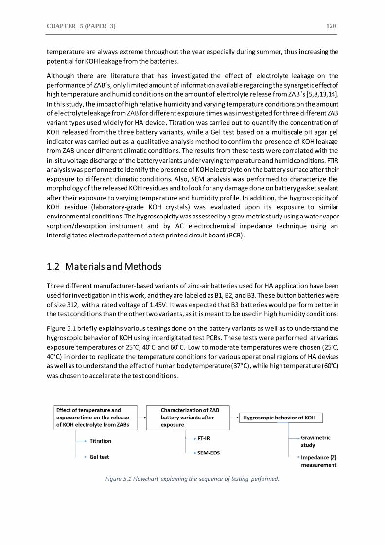
CHAPTER 5 (PAPER 3) 120 temperature are always extreme throughout the year especially during summer, thus increasing the
potential for KOH leakage from the batteries.
Although there are literature that has investigated the effect of electrolyte leakage on the
performance of ZAB’s, only limited amount of information available regarding the synergetic effect of
high temperature and humid conditions on the amount of electrolyte release from ZAB ’s [5,8,13,14].
In this study, the impact of high relative humidity and varying temperature conditions on the amount
of electrolyte leakage from ZAB for different exposure times was investigated for three different ZAB
variant types used widely for HA device. Titration was carried out to quantify the concentration of
KOH released from the three battery variants, while a Gel test based on a multiscale pH agar gel
indicator was carried out as a qualitative analysis method to confirm the presence of KOH leakage
from ZAB under different climatic conditions. The results from these tests were correlated with the
in-situ voltage discharge of the battery variants under varying temperature and humid conditions. FTIR
analysis was performed to identify the presence of KOH electrolyte on the battery surface after their
exposure to different climatic conditions. Also, SEM analysis was performed to characterize the
morphology of the released KOH residues and to look for any damage done on battery gasket sealant
after their exposure to varying temperature and humidity profile. In addition, the hygroscopicity of
KOH residue (laboratory-grade KOH crystals) was evaluated upon its exposure to similar
environmental conditions. The hygroscopicity was assessed by a gravimetric study using a water vapor
sorption/desorption instrument and by AC electrochemical impedance technique using an
interdigitated electrode pattern of a test printed circuit board (PCB).
1.2 Materials and Methods
Three different manufacturer-based variants of zinc-air batteries used for HA application have been
used for investigation in this work, and they are labeled as B1, B2, and B3. These button batteries were
of size 312, with a rated voltage of 1.45V. It was expected that B3 batteries would perform better in
the test conditions than the other two variants, as it is meant to be used in high humidity conditions.
Figure 5.1 briefly explains various testings done on the battery variants as well as to understand the
hygroscopic behavior of KOH using interdigitated test PCBs. These tests were performed at various
exposure temperatures of 25°C, 40°C and 60°C. Low to moderate temperatures were chosen (25°C,
40°C) in order to replicate the temperature conditions for various operational regions of HA devices
as well as to understand the effect of human body temperature (37°C), while high temperature (60°C)
was chosen to accelerate the test conditions.
Figure 5.1 Flowchart explaining the sequence of testing performed.
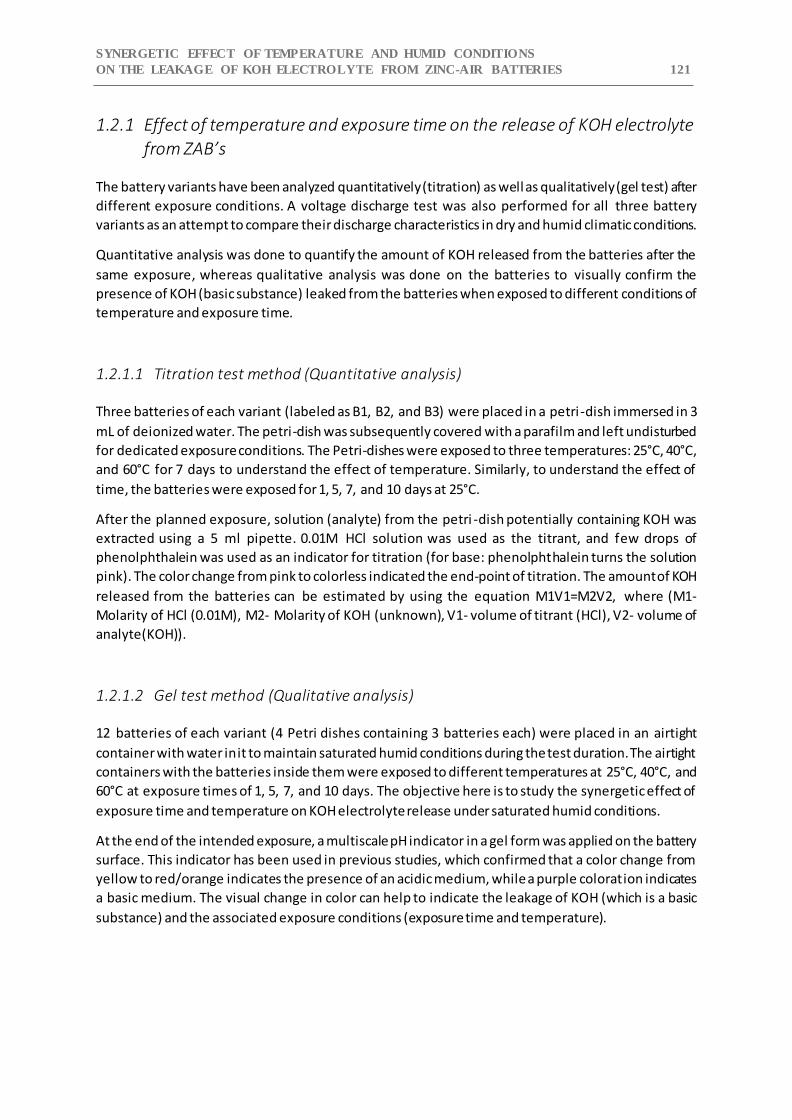
SYNERGETIC EFFECT OF TEMPERATURE AND HUMID CONDITIONS
ON THE LEAKAGE OF KOH ELECTROLYTE FROM ZINC-AIR BATTERIES 121
1.2.1 Effect of temperature and exposure time on the release of KOH electrolyte
from ZAB’s
The battery variants have been analyzed quantitatively (titration) as well as qualitatively (gel test) after
different exposure conditions. A voltage discharge test was also performed for all three battery
variants as an attempt to compare their discharge characteristics in dry and humid climatic conditions.
Quantitative analysis was done to quantify the amount of KOH released from the batteries after the
same exposure, whereas qualitative analysis was done on the batteries to visually confirm the
presence of KOH (basic substance) leaked from the batteries when exposed to different conditions of
temperature and exposure time.
1.2.1.1 Titration test method (Quantitative analysis)
Three batteries of each variant (labeled as B1, B2, and B3) were placed in a petri-dish immersed in 3
mL of deionized water. The petri-dish was subsequently covered with a parafilm and left undisturbed
for dedicated exposure conditions. The Petri-dishes were exposed to three temperatures: 25°C, 40°C,
and 60°C for 7 days to understand the effect of temperature. Similarly, to understand the effect of
time, the batteries were exposed for 1, 5, 7, and 10 days at 25°C.
After the planned exposure, solution (analyte) from the petri -dish potentially containing KOH was
extracted using a 5 ml pipette. 0.01M HCl solution was used as the titrant, and few drops of
phenolphthalein was used as an indicator for titration (for base: phenolphthalein turns the solution
pink). The color change from pink to colorless indicated the end-point of titration. The amount of KOH
released from the batteries can be estimated by using the equation M1V1=M2V2, where (M1-
Molarity of HCl (0.01M), M2- Molarity of KOH (unknown), V1- volume of titrant (HCl), V2- volume of
analyte(KOH)).
1.2.1.2 Gel test method (Qualitative analysis)
12 batteries of each variant (4 Petri dishes containing 3 batteries each) were placed in an airtight
container with water in it to maintain saturated humid conditions during the test duration. The airtight
containers with the batteries inside them were exposed to different temperatures at 25°C, 40°C, and
60°C at exposure times of 1, 5, 7, and 10 days. The objective here is to study the synergetic effect of
exposure time and temperature on KOH electrolyte release under saturated humid conditions.
At the end of the intended exposure, a multiscale pH indicator in a gel form was applied on the battery
surface. This indicator has been used in previous studies, which confirmed that a color change from
yellow to red/orange indicates the presence of an acidic medium, while a purple coloration indicates
a basic medium. The visual change in color can help to indicate the leakage of KOH (which is a basic
substance) and the associated exposure conditions (exposure time and temperature).
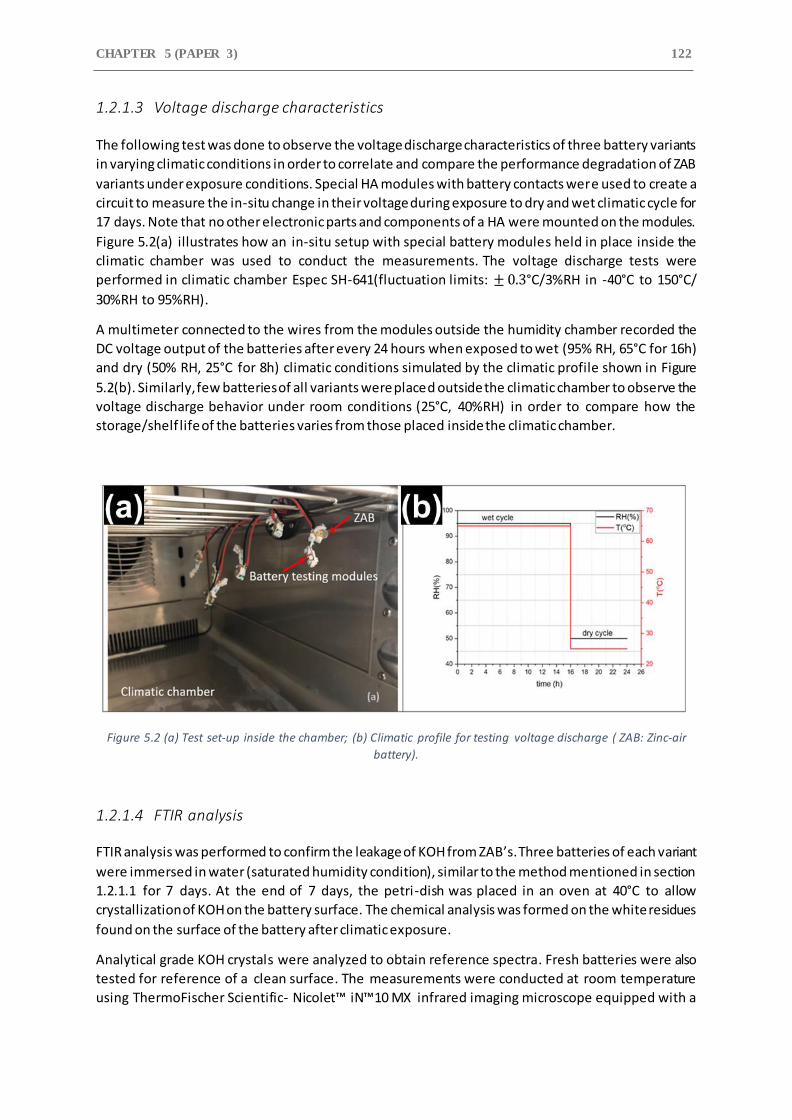
CHAPTER 5 (PAPER 3) 122
1.2.1.3 Voltage discharge characteristics
The following test was done to observe the voltage discharge characteristics of three battery variants
in varying climatic conditions in order to correlate and compare the performance degradation of ZAB
variants under exposure conditions. Special HA modules with battery contacts were used to create a
circuit to measure the in-situ change in their voltage during exposure to dry and wet climatic cycle for
17 days. Note that no other electronic parts and components of a HA were mounted on the modules.
Figure 5.2(a) illustrates how an in-situ setup with special battery modules held in place inside the
climatic chamber was used to conduct the measurements. The voltage discharge tests were
performed in climatic chamber Espec SH-641(fluctuation limits: ± 0.3°C/3%RH in -40°C to 150°C/
30%RH to 95%RH).
A multimeter connected to the wires from the modules outside the humidity chamber recorded the
DC voltage output of the batteries after every 24 hours when exposed to wet (95% RH, 65°C for 16h)
and dry (50% RH, 25°C for 8h) climatic conditions simulated by the climatic profile shown in Figure
5.2(b). Similarly, few batteries of all variants were placed outside the climatic chamber to observe the
voltage discharge behavior under room conditions (25°C, 40%RH) in order to compare how the
storage/shelf life of the batteries varies from those placed inside the climatic chamber.
Figure 5.2 (a) Test set-up inside the chamber; (b) Climatic profile for testing voltage discharge ( ZAB: Zinc-air
battery).
1.2.1.4 FTIR analysis
FTIR analysis was performed to confirm the leakage of KOH from ZAB’s. Three batteries of each variant
were immersed in water (saturated humidity condition), similar to the method mentioned in section
1.2.1.1 for 7 days. At the end of 7 days, the petri-dish was placed in an oven at 40°C to allow
crystallization of KOH on the battery surface. The chemical analysis was formed on the white residues
found on the surface of the battery after climatic exposure.
Analytical grade KOH crystals were analyzed to obtain reference spectra. Fresh batteries were also
tested for reference of a clean surface. The measurements were conducted at room temperature
using ThermoFischer Scientific- Nicolet™ iN™10 MX infrared imaging microscope equipped with a
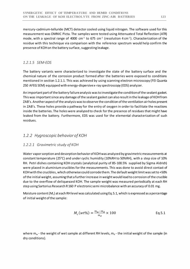
SYNERGETIC EFFECT OF TEMPERATURE AND HUMID CONDITIONS
ON THE LEAKAGE OF KOH ELECTROLYTE FROM ZINC-AIR BATTERIES 123
mercury-cadmium-telluride (MCT) detector cooled using liquid nitrogen. The software used for this
measurement was OMNIC Picta. The samples were tested using Attenuated Total Reflection (ATR)
mode, with a spectral range of 4000 cm-1 to 675 cm-1 (resolution 4 cm-1). Characterization of the
residue with this technique via comparison with the reference spectrum would help confirm the
presence of KOH on the battery surface, suggesting leakage.
1.2.1.5 SEM-EDS
The battery variants were characterized to investigate the state of the battery surface and the
chemical nature of the corrosion product formed after the batteries were exposed to conditions
mentioned in section 1.2.1.1. This was achieved by using scanning electron microscopy (FEI Quanta
250 AFEG SEM) equipped with energy-dispersive x-ray spectroscopy (EDS) analyzer.
An important part of the battery failure analysis was to investigate the condition of the sealant gasket.
This was important since any damage of the sealant gasket can also result in the leakage of KOH from
ZAB’s. Another aspect of the analysis was to observe the condition of the ventilation air holes present
in ZAB’s. These holes provide a pathway for the entry of oxygen in order to facilitate the reactions
inside the batteries. The holes were analyzed to check for the presence of residues that might have
leaked from the battery. Furthermore, EDS was used for the elemental characterization of such
residues.
1.2.2 Hygroscopic behavior of KOH
1.2.2.1 Gravimetric study of KOH
Water vapor sorption and desorption behavior of KOH was analyzed by gravimetric measurements at
constant temperature (25°C) and under cyclic humidity (10%RH to 50%RH), with a step size of 10%
RH. Petri dishes containing KOH crystals (analytical purity of 85-100.5% supplied by Sigma Aldrich)
were placed in aluminium crucibles for the measurements. This was done to avoid direct contact of
KOH with the crucibles, which otherwise could corrode them. The default weight limit was set to +50%
of the initial weight, assuming that a further increase in weight would lead to corrosion of the crucible
due to the overflow of deliquesced KOH. The sample weight was measured periodically at each RH
step using Sartorius Research R 160 P electronic semi microbalance with an accuracy of 0.01 mg.
Moisture content (Mc) at each RH level was calculated using Eq.5.1, which is expressed as a percentage
of initial weight of the sample:
𝑀𝑐(𝑤𝑡%) =𝑚𝑤 −𝑚𝑑
𝑚𝑑× 100 Eq.5.1
where mw - the weight of wet sample at different RH levels, md - the initial weight of the sample (in
dry conditions).
CHAPTER 5 (PAPER 3) 124 Water sorption and desorption isotherms were generated based on the moisture content in KOH
crystals with increasing and decreasing RH levels. The relative humidity levels for deliquescence (DRH)
and efflorescence (ERH) were determined based on the increase in weight (for DRH) and reduction of
weight (for ERH).
1.2.2.2 Impedance test
AC electrochemical measurements were carried out using a test PCB with interdigitated electrode
pattern, as shown in Figure 5.3. The surface finish of the PCB was with hot air solder leveling (HASL).
This test was done to study the moisture absorption behavior of KOH under constant temperature
and varying humidity conditions and their effect on impedance behavior. The dimensions of the comb
pattern on the SIR test PCBs were 13 mm x 25 mm (surface area of 325 mm2), as seen in Figure 5.3,
with a pitch distance of 300 µm.
Figure 5.3 SIR test PCB used for testing.
Prior to testing, the SIR test boards were thoroughly rinsed using deionized water (conductivity of 18.2
MΩ.cm at 25°C) and isopropyl alcohol (analytical purity of 99.8%) thrice, followed by drying with
pressurized air. The wires were soldered to the electrodes and finally, KOH residues (laboratory-grade
KOH crystals from Sigma Aldrich- 85-100.5% analytical purity) were applied on the surface. EIS
measurements were conducted in the climatic chamber ARL-0680 (fluctuation limits: ± 0.3°C/2.5%RH
in -45°C to 180°C/ 10%RH to 98%RH).
The SIR test boards pre-contaminated with KOH residue (surface concentrations of 100 µg/cm2) were
left undisturbed at room temperature for the solvent to evaporate. The boards were subsequently
placed in a desiccator for a day, to remove any volatile compounds that might have been present on
it.
During testing, initially the test boards were placed in the climatic chamber at 10%RH and 25°C for 1
hour for the samples and chamber to reach equilibrium. This was followed by the cyclic climatic profile
where RH increased from 10% to 98% for 16 hours, followed by a decrease in RH from 98% to 10% for
16 hours. Finally, the RH was kept constant at 10% for 16h to observe the crystallization ( efflorescence)
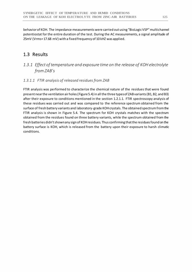
SYNERGETIC EFFECT OF TEMPERATURE AND HUMID CONDITIONS
ON THE LEAKAGE OF KOH ELECTROLYTE FROM ZINC-AIR BATTERIES 125
behavior of KOH. The impedance measurements were carried out using “BioLogic VSP” multichannel
potentiostat for the entire duration of the test. During the AC measurements, a signal amplitude of
25mV (Vrms= 17.68 mV) with a fixed frequency of 10 kHZ was applied.
1.3 Results
1.3.1 Effect of temperature and exposure time on the release of KOH electrolyte
from ZAB’s
1.3.1.1 FTIR analysis of released residues from ZAB
FTIR analysis was performed to characterize the chemical nature of the residues that were found
present near the ventilation air holes (Figure 5.4) in all the three types of ZAB variants (B1, B2, and B3)
after their exposure to conditions mentioned in the section 1.2.1.1. FTIR spectroscopy analysis of
these residues was carried out and was compared to the reference spectrum obtained from the
surface of fresh battery variants and laboratory-grade KOH crystals. The obtained spectrum from the
FTIR analysis is shown in Figure 5.4. The spectrum for KOH crystals matches with the spectrum
obtained from the residues found on three battery variants, while the spectrum obtained from the
fresh batteries didn’t shown any sign of KOH residues. Thus confirming that the residues found on the
battery surface is KOH, which is released from the battery upon their exposure to harsh climatic
conditions.
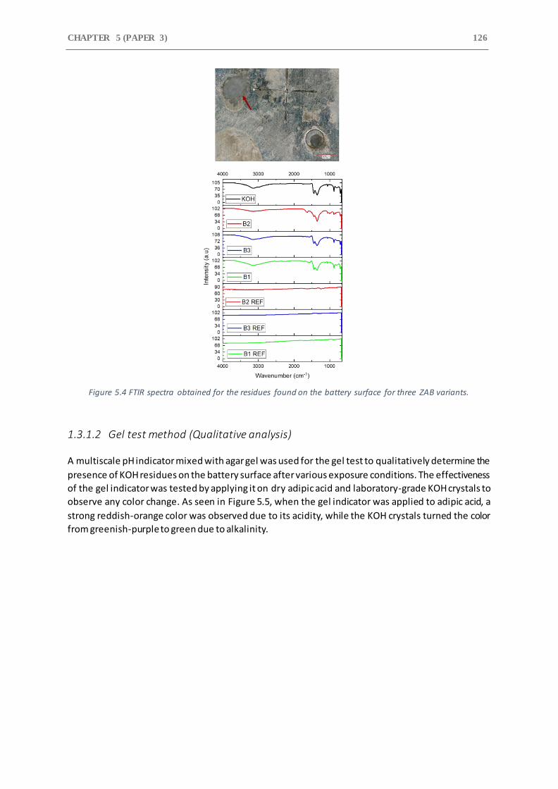
CHAPTER 5 (PAPER 3) 126
Figure 5.4 FTIR spectra obtained for the residues found on the battery surface for three ZAB variants.
1.3.1.2 Gel test method (Qualitative analysis)
A multiscale pH indicator mixed with agar gel was used for the gel test to qualitatively determine the
presence of KOH residues on the battery surface after various exposure conditions. The effectiveness
of the gel indicator was tested by applying it on dry adipic acid and laboratory-grade KOH crystals to
observe any color change. As seen in Figure 5.5, when the gel indicator was applied to adipic acid, a
strong reddish-orange color was observed due to its acidity, while the KOH crystals turned the color
from greenish-purple to green due to alkalinity.
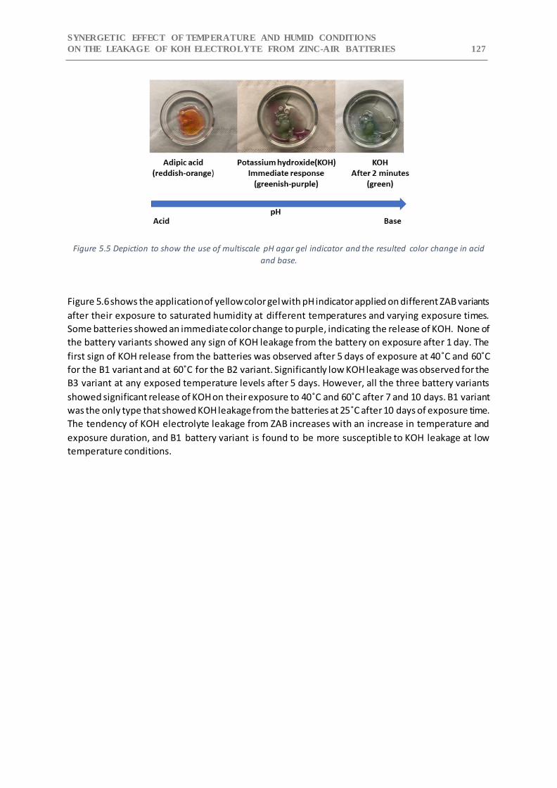
SYNERGETIC EFFECT OF TEMPERATURE AND HUMID CONDITIONS
ON THE LEAKAGE OF KOH ELECTROLYTE FROM ZINC-AIR BATTERIES 127
Figure 5.5 Depiction to show the use of multiscale pH agar gel indicator and the resulted color change in acid
and base.
Figure 5.6 shows the application of yellow color gel with pH indicator applied on different ZAB variants
after their exposure to saturated humidity at different temperatures and varying exposure times.
Some batteries showed an immediate color change to purple, indicating the release of KOH. None of
the battery variants showed any sign of KOH leakage from the battery on exposure after 1 day. The
first sign of KOH release from the batteries was observed after 5 days of exposure at 40˚C and 60˚C
for the B1 variant and at 60˚C for the B2 variant. Significantly low KOH leakage was observed for the
B3 variant at any exposed temperature levels after 5 days. However, all the three battery variants
showed significant release of KOH on their exposure to 40˚C and 60˚C after 7 and 10 days. B1 variant
was the only type that showed KOH leakage from the batteries at 25˚C after 10 days of exposure time.
The tendency of KOH electrolyte leakage from ZAB increases with an increase in temperature and
exposure duration, and B1 battery variant is found to be more susceptible to KOH leakage at low
temperature conditions.
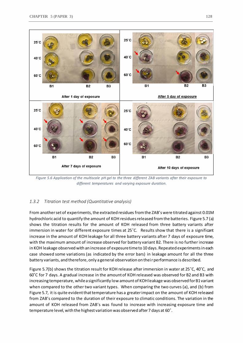
CHAPTER 5 (PAPER 3) 128
Figure 5.6 Application of the multiscale pH gel to the three different ZAB variants after their exposure to
different temperatures and varying exposure duration.
1.3.2 Titration test method (Quantitative analysis)
From another set of experiments, the extracted residues from the ZAB’s were titrated against 0.01M
hydrochloric acid to quantify the amount of KOH residues released from the batteries. Figure 5.7 (a)
shows the titration results for the amount of KOH released from three battery variants after
immersion in water for different exposure times at 25˚C. Results show that there is a significant
increase in the amount of KOH leakage for all three battery variants after 7 days of exposure time,
with the maximum amount of increase observed for battery variant B2. There is no further increase
in KOH leakage observed with an increase of exposure time to 10 days. Repeated experiments in each
case showed some variations (as indicated by the error bars) in leakage amount for all the three
battery variants, and therefore, only a general observation on thei r performance is described.
Figure 5.7(b) shows the titration result for KOH release after immersion in water at 25˚C, 40˚C, and
60˚C for 7 days. A gradual increase in the amount of KOH released was observed for B2 and B3 with
increasing temperature, while a significantly low amount of KOH leakage was observed for B1 variant
when compared to the other two variant types. When comparing the two curves (a), and (b) from
Figure 5.7, it is quite evident that temperature has a greater impact on the amount of KOH released
from ZAB’s compared to the duration of their exposure to climatic conditions. The variation in the
amount of KOH released from ZAB’s was found to increase with increasing exposure time and
temperature level, with the highest variation was observed after 7 days at 60˚.
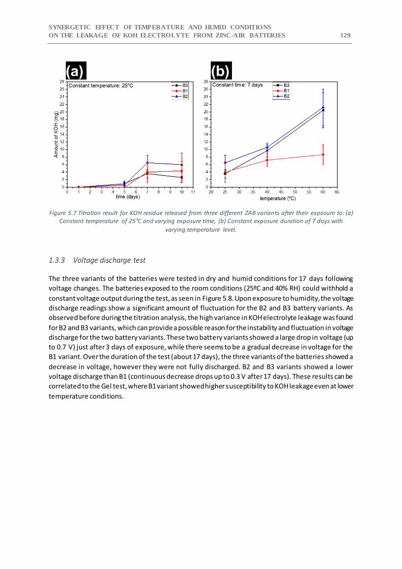
SYNERGETIC EFFECT OF TEMPERATURE AND HUMID CONDITIONS
ON THE LEAKAGE OF KOH ELECTROLYTE FROM ZINC-AIR BATTERIES 129
Figure 5.7 Titration result for KOH residue released from three different ZAB variants after their exposure to: (a)
Constant temperature of 25°C and varying exposure time, (b) Constant exposure duration of 7 days with
varying temperature level.
1.3.3 Voltage discharge test
The three variants of the batteries were tested in dry and humid conditions for 17 days following
voltage changes. The batteries exposed to the room conditions (25ºC and 40% RH) could withhold a
constant voltage output during the test, as seen in Figure 5.8. Upon exposure to humidity, the voltage
discharge readings show a significant amount of fluctuation for the B2 and B3 battery variants. As
observed before during the titration analysis, the high variance in KOH electrolyte leakage was found
for B2 and B3 variants, which can provide a possible reason for the instability and fluctuation in voltage
discharge for the two battery variants. These two battery variants showed a large drop in voltage (up
to 0.7 V) just after 3 days of exposure, while there seems to be a gradual decrease in voltage for the
B1 variant. Over the duration of the test (about 17 days), the three variants of the batteries showed a
decrease in voltage, however they were not fully discharged. B2 and B3 variants showed a lower
voltage discharge than B1 (continuous decrease drops up to 0.3 V after 17 days). These results can be
correlated to the Gel test, where B1 variant showed higher susceptibility to KOH leakage even at lower
temperature conditions.
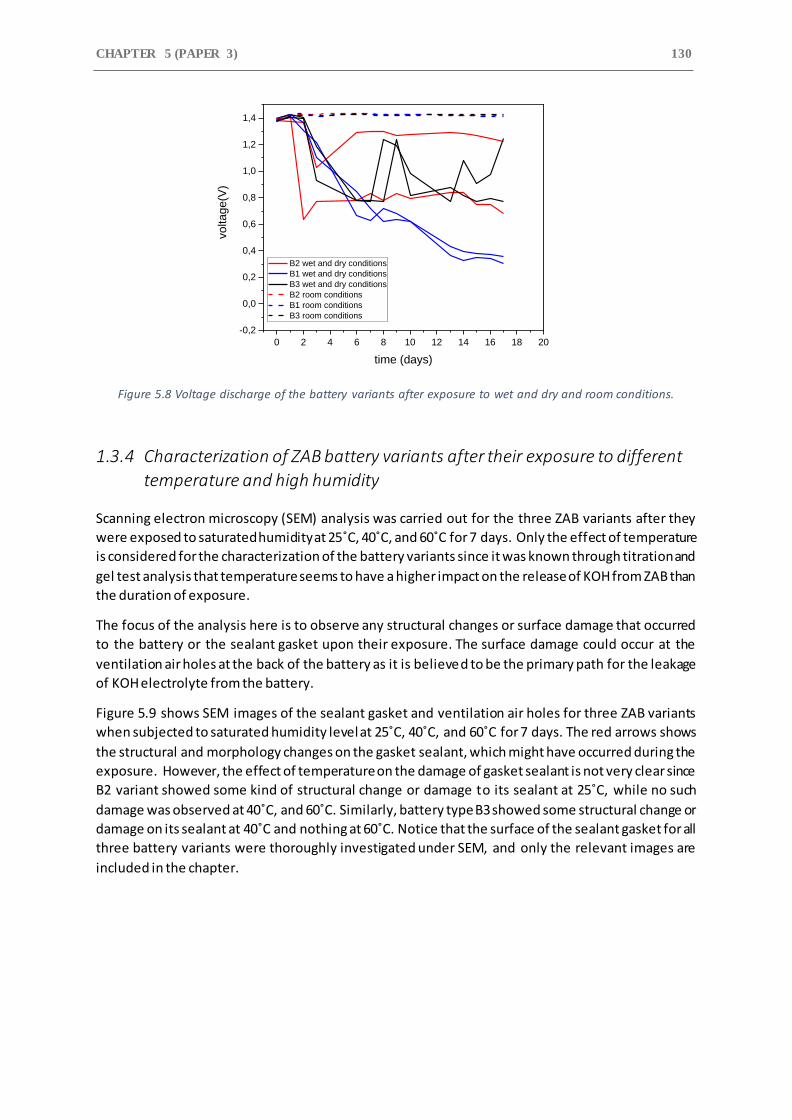
CHAPTER 5 (PAPER 3) 130
Figure 5.8 Voltage discharge of the battery variants after exposure to wet and dry and room conditions.
1.3.4 Characterization of ZAB battery variants after their exposure to different
temperature and high humidity
Scanning electron microscopy (SEM) analysis was carried out for the three ZAB variants after they
were exposed to saturated humidity at 25˚C, 40˚C, and 60˚C for 7 days. Only the effect of temperature
is considered for the characterization of the battery variants since it was known through titration and
gel test analysis that temperature seems to have a higher impact on the release of KOH from ZAB than
the duration of exposure.
The focus of the analysis here is to observe any structural changes or surface damage that occurred
to the battery or the sealant gasket upon their exposure. The surface damage could occur at the
ventilation air holes at the back of the battery as it is believed to be the primary path for the leakage
of KOH electrolyte from the battery.
Figure 5.9 shows SEM images of the sealant gasket and ventilation air holes for three ZAB variants
when subjected to saturated humidity level at 25˚C, 40˚C, and 60˚C for 7 days. The red arrows shows
the structural and morphology changes on the gasket sealant, which might have occurred during the
exposure. However, the effect of temperature on the damage of gasket sealant is not very clear since
B2 variant showed some kind of structural change or damage to its sealant at 25˚C, while no such
damage was observed at 40˚C, and 60˚C. Similarly, battery type B3 showed some structural change or
damage on its sealant at 40˚C and nothing at 60˚C. Notice that the surface of the sealant gasket for all
three battery variants were thoroughly investigated under SEM, and only the relevant images are
included in the chapter.
0 2 4 6 8 10 12 14 16 18 20
-0,2
0,0
0,2
0,4
0,6
0,8
1,0
1,2
1,4
voltage(V
)
time (days)
B2 wet and dry conditions
B1 wet and dry conditions
B3 wet and dry conditions
B2 room conditions
B1 room conditions
B3 room conditions
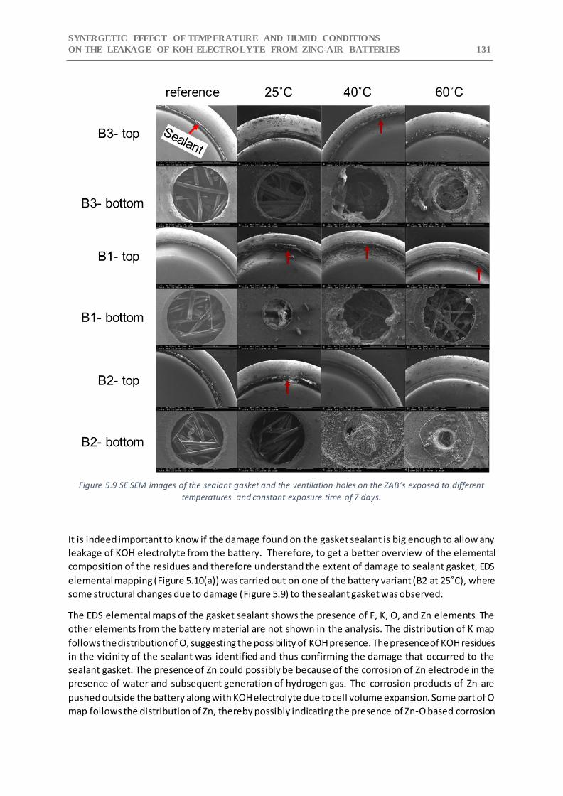
SYNERGETIC EFFECT OF TEMPERATURE AND HUMID CONDITIONS
ON THE LEAKAGE OF KOH ELECTROLYTE FROM ZINC-AIR BATTERIES 131
Figure 5.9 SE SEM images of the sealant gasket and the ventilation holes on the ZAB’s exposed to different
temperatures and constant exposure time of 7 days.
It is indeed important to know if the damage found on the gasket sealant is big enough to allow any
leakage of KOH electrolyte from the battery. Therefore, to get a better overview of the elemental
composition of the residues and therefore understand the extent of damage to sealant gasket, EDS
elemental mapping (Figure 5.10(a)) was carried out on one of the battery variant (B2 at 25˚C), where
some structural changes due to damage (Figure 5.9) to the sealant gasket was observed.
The EDS elemental maps of the gasket sealant shows the presence of F, K, O, and Zn elements. The
other elements from the battery material are not shown in the analysis. The distribution of K map
follows the distribution of O, suggesting the possibility of KOH presence. The presence of KOH residues
in the vicinity of the sealant was identified and thus confirming the damage that occurred to the
sealant gasket. The presence of Zn could possibly be because of the corrosion of Zn electrode in the
presence of water and subsequent generation of hydrogen gas. The corrosion products of Zn are
pushed outside the battery along with KOH electrolyte due to cell volume expansion. Some part of O
map follows the distribution of Zn, thereby possibly indicating the presence of Zn-O based corrosion

CHAPTER 5 (PAPER 3) 132 products. F element comes from the material composition of gasket sealant. It is possible that the
KOH residues are moved to the sealant gasket area upon its release from the ventilation holes present
at the backside. However, the EDS mapping showed that the characteristics X-rays of K, O and Zn
elements are more pronounced at the damaged sealant gasket surface, than other areas near the
gasket.
The ventilation air holes shows the presence of residues in and around it for all the th ree battery
variants (Figure 5.9). The amount of residues seems to be greater in amount for batteries exposed to
higher temperatures namely 40˚C, and 60˚C. The residues also seem to have clogged the entire
ventilation hole for B2 variant exposed to 40˚C and 60˚C, while a similar observation was made for B3
variant when exposed to 60˚C. High amount of KOH residue are observed at the air holes for B2 variant
compared to the other two variant type. EDS elemental mapping was done in order to get a better
overview of the elemental composition of these residues at air holes. The EDS elemental maps ( Figure
5.10(b)) shows that it consists of K, Zn, and O. The distribution of Zn and K follows the distribution of
O, suggesting the presence of possible KOH residue along with Zn-O based corrosion products.
Figure 5.10 Secondary electron images and EDS elemental maps for B2 variant after exposure: (a) Sealant
gasket, (b) Residues found on ventilation holes.
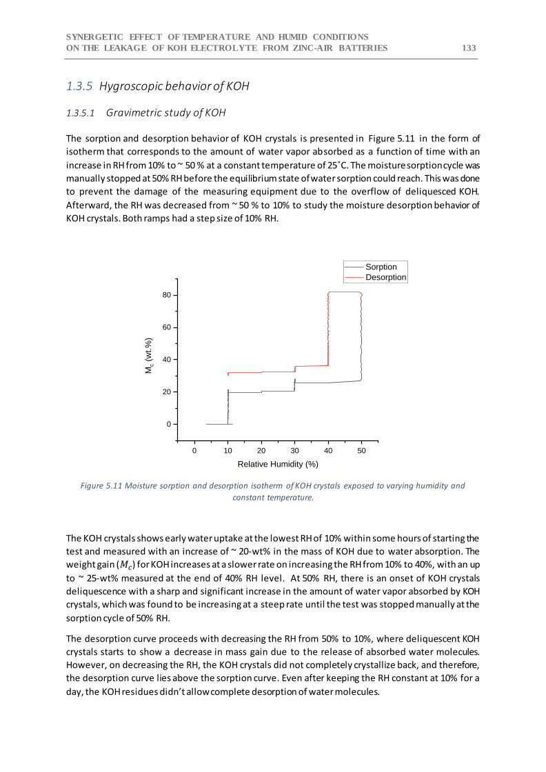
SYNERGETIC EFFECT OF TEMPERATURE AND HUMID CONDITIONS
ON THE LEAKAGE OF KOH ELECTROLYTE FROM ZINC-AIR BATTERIES 133
1.3.5 Hygroscopic behavior of KOH
1.3.5.1 Gravimetric study of KOH
The sorption and desorption behavior of KOH crystals is presented in Figure 5.11 in the form of
isotherm that corresponds to the amount of water vapor absorbed as a function of time with an
increase in RH from 10% to ~ 50 % at a constant temperature of 25˚C. The moisture sorption cycle was
manually stopped at 50% RH before the equilibrium state of water sorption could reach. This was done
to prevent the damage of the measuring equipment due to the overflow of deliquesced KOH.
Afterward, the RH was decreased from ~ 50 % to 10% to study the moisture desorption behavior of
KOH crystals. Both ramps had a step size of 10% RH.
Figure 5.11 Moisture sorption and desorption isotherm of KOH crystals exposed to varying humidity and
constant temperature.
The KOH crystals shows early water uptake at the lowest RH of 10% within some hours of starting the
test and measured with an increase of ~ 20-wt% in the mass of KOH due to water absorption. The
weight gain (𝑀𝑐) for KOH increases at a slower rate on increasing the RH from 10% to 40%, with an up
to ~ 25-wt% measured at the end of 40% RH level. At 50% RH, there is an onset of KOH crystals
deliquescence with a sharp and significant increase in the amount of water vapor absorbed by KOH
crystals, which was found to be increasing at a steep rate until the test was stopped manually at the
sorption cycle of 50% RH.
The desorption curve proceeds with decreasing the RH from 50% to 10%, where deliquescent KOH
crystals starts to show a decrease in mass gain due to the release of absorbed water molecules.
However, on decreasing the RH, the KOH crystals did not completely crystallize back, and therefore,
the desorption curve lies above the sorption curve. Even after keeping the RH constant at 10% for a
day, the KOH residues didn’t allow complete desorption of water molecules.
0 10 20 30 40 50
0
20
40
60
80
Mc (
wt.%
)
Relative Humidity (%)
Sorption
Desorption
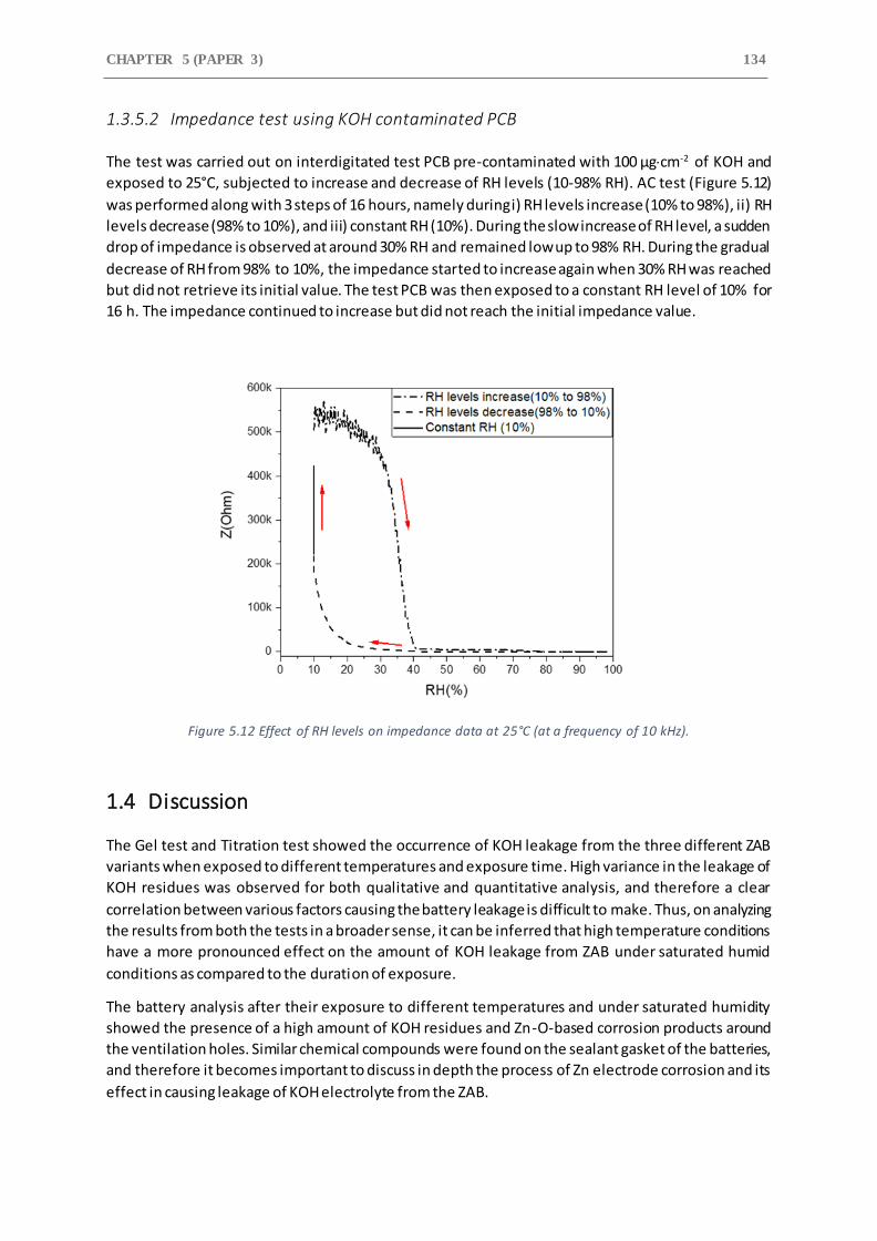
CHAPTER 5 (PAPER 3) 134
1.3.5.2 Impedance test using KOH contaminated PCB
The test was carried out on interdigitated test PCB pre-contaminated with 100 μgcm-2 of KOH and
exposed to 25°C, subjected to increase and decrease of RH levels (10-98% RH). AC test (Figure 5.12)
was performed along with 3 steps of 16 hours, namely during i) RH levels increase (10% to 98%), ii) RH
levels decrease (98% to 10%), and iii) constant RH (10%). During the slow increase of RH level, a sudden
drop of impedance is observed at around 30% RH and remained low up to 98% RH. During the gradual
decrease of RH from 98% to 10%, the impedance started to increase again when 30% RH was reached
but did not retrieve its initial value. The test PCB was then exposed to a constant RH level of 10% for
16 h. The impedance continued to increase but did not reach the initial impedance value.
Figure 5.12 Effect of RH levels on impedance data at 25°C (at a frequency of 10 kHz).
1.4 Discussion
The Gel test and Titration test showed the occurrence of KOH leakage from the three different ZAB
variants when exposed to different temperatures and exposure time. High variance in the leakage of
KOH residues was observed for both qualitative and quantitative analysis, and therefore a clear
correlation between various factors causing the battery leakage is difficult to make. Thus, on analyzing
the results from both the tests in a broader sense, it can be inferred that high temperature conditions
have a more pronounced effect on the amount of KOH leakage from ZAB under saturated humid
conditions as compared to the duration of exposure.
The battery analysis after their exposure to different temperatures and under saturated humidity
showed the presence of a high amount of KOH residues and Zn-O-based corrosion products around
the ventilation holes. Similar chemical compounds were found on the sealant gasket of the batteries,
and therefore it becomes important to discuss in depth the process of Zn electrode corrosion and its
effect in causing leakage of KOH electrolyte from the ZAB.
SYNERGETIC EFFECT OF TEMPERATURE AND HUMID CONDITIONS
ON THE LEAKAGE OF KOH ELECTROLYTE FROM ZINC-AIR BATTERIES 135
The active anode Zn material of the ZAB undergoes an oxidation process during the cell discharge and
involves several other processes such as dissolution of ions in the solution, ion diffusion in the
electrolyte, and precipitation into a solid phase when the solubility limit is reached [24]. However, in
conditions when water is present inside the battery, the corrosion of Zn electrode can take place in
an aqueous KOH electrolyte to produce hydrogen gas according to reaction 5.2.
𝑍𝑛 + 2𝐻2𝑂 ⟶ 𝑍𝑛(𝑂𝐻)2 + 𝐻2 ↑ 5.2
Corrosion of Zn in the presence of water and KOH electrolyte will produce a black deposit and
hydrogen evolution, which is known to cause cell rupture, damage of the sealant gasket, and leakage
of electrolyte [14,24]. Also, it is worth mentioning that under lower pH electrolyte ( pH < 13), more
stable type II 𝑍𝑛𝑂 is formed due to the passivation of Zn, which can hinder the further dissolution of
Zn, and can make the anode surface electrochemically inactive, thus making the battery inconvenient
to operate [25].
The voltage discharge test showed high fluctuation in voltage readings of B1 and B2 battery variants,
whereas a gradual decrease of voltages was observed for B1. This fluctuation in the voltage during
discharge can be attributed to the lowering of KOH electrolyte molarity due to the ingress of water
vapor inside the cell and diluting the electrolyte, thus affecting its performance [8]. Furthermore, the
release of KOH and the production of carbonate products during humidity and temperature exposure
can clog the ventilation holes of the battery, which can decrease the availability of oxygen at the air
electrode, thus causing performance degradation of the batteries.
The water absorption test showed that KOH is highly hygroscopic (Figure 5.11) and starts absorbing
moisture at RH level as low as 10% (about 20 wt%). This was correlated with the EIS test ( Figure 5.12),
where the impedance starts to drop at low RH levels, with a subsequent sudden drop at around 30%
RH. During the drying cycle, a hysteresis can be observed, and even after a constant exposure at 10%
RH for 16h, low impedance levels indicate the presence of a remaining water layer on the surface of
the test PCB. The hygroscopic nature of the residues was clearly depicted in this test and therefore,
the leakage of KOH electrolyte inside an electronic device can lower the RH boundary for the device
through the process of deliquescence and will therefore cause thick water layer formation. Variety of
electronics failure modes due to humidity has been reported previously, of which the thickness of
water layer formed on the electronic components like PCBA is the most critical factor determining the
reliability of electronics [26–28]. This is significantly affected by the presence of ionic contamination
on the PCBA surface and their hygroscopicity.
Our previous work on the failure analysis of field failed hearing aids from various markets revealed
that KOH electrolyte leakage from the ZAB power source was the major failure cause [22,23]. The
failure percentage of devices due to KOH was higher for tropical regions. The KOH residues caused
degradation of conformal coatings on PCBA and other hand soldering areas, which subsequently
caused severe localized corrosion attacks. Due to their high solubility, the KOH residues were able to
easily dissolve in the moisture and human sweat formed inside the device upon exposure to the
human body and harsh climatic conditions of tropical regions. As a result, they ionized on dissolving
into the liquid to form 𝑂𝐻− ions, which traveled to various components of the HA device and in
particular, affected the components having high electric potential. For example, the microphone
component of HA, due to the presence of a high electrical charge on its membrane plate were able to
preferentially attract hydroxide ions of KOH and thereby endured high corrosion on its surface
mounted electrical components (capacitors and resistors), leading to their complete failure. Hence,
CHAPTER 5 (PAPER 3) 136 the presence of these hygroscopic KOH residues on the surface of electronic boards and components
can be detrimental to electronics reliability due to their ease of absorbing moisture at lower RH levels.
The critical RH (cRH) for hygroscopic substance, also defined as the deliquescence point, is when the
phase transformation occurs from a solid to a saturated solution at a particular RH level. Above this
cRH level, there exists a chemical potential between the water on the surface of the crystal and the
water present in the air. This gradient acts as a driving force for water condensation to take place on
the crystal and gradually leads to the dissolution of the crystals if the conditions are maintained above
cRH [29]. Thus, the presence of an aggressive environment (elevated temperature and high humidity),
along with the presence of KOH, provide an extremely suitable condition for the formation of a
corrosion cell and leads to the reduction of surface insulation resistance (SIR) between the conductors
[30], high leak current and possible occurrence of electrochemical migration (ECM) [31,32].
Several studies have reported previously that the solder flux residues that remain on the surface of
the PCBA surface after the soldering process can lower the corrosion reliability of the device in humid
environment [29,32,33]. These residues showed high hygroscopic behavior and solubility i n water,
which resulted in their high susceptibility to form electrolyte with high conductivity, and showed
increase leak current and ECM failures [34,35]. Deliquescence relative humidity (DRH) reported in
previous studies for flux activators, and salt residues showed that compared to flux activators, salt
residues have low RH for deliquescence, with Cl salts of Mg and Ca showed the lowest RH for
deliquescence at 44% and 29% RH respectively. Similarly, in comparison, the presence of alkaline KOH
residues inside an electronic device should exhibit similar RH for deliquescence like salt residues,
which can accelerate the corrosion of electronic board assembly and its components.
1.5 Conclusion
The Gel and Titration test revealed the release of KOH electrolyte from the three ZAB variants,
particularly at high temperatures and saturated humid conditions, was found to increase with
increasing exposure duration. Among the two effects, the temperature has a higher impact
on the leakage of KOH than exposure duration under saturated humid conditions. High
variance in the amount of KOH leakage from ZAB was observed for B2 and B3 and was
correlated with the fluctuation in voltage drop observed during the voltage discharge test. B1
showed higher susceptibility towards KOH leakage from ZAB on exposure to different
temperature conditions.
SEM-EDS analysis of the battery surface after their exposure to different temperatures under
saturated humidity showed Zn-O-based corrosion products along with KOH residues.
Outgassing caused by the release of hydrogen gas during the corrosion of Zn electrode was
linked to the damage found on the battery sealant gasket.
KOH residues were found to be highly hygroscopic in nature and showed deliquescence at a
low RH level of ~50%. Similar hygroscopic behavior of KOH residues was observed during EIS
testing. This hygroscopic behavior of KOH can lead to the formation of a sufficient amount of
water on electronics PCBA surface with high conductivity, thus causing a drop in SIR and
increases the risk of other corrosion failure modes.

SYNERGETIC EFFECT OF TEMPERATURE AND HUMID CONDITIONS
ON THE LEAKAGE OF KOH ELECTROLYTE FROM ZINC-AIR BATTERIES 137
1.6 Acknowledgment
This research reported here was conducted as a part of the Industrial PhD project, and the authors
would like to acknowledge the funding and help received from Innovation Fund Denmark.
CHAPTER 5 (PAPER 3) 138
References
[1] Y. Li, J. Lu, Metal-Air Batteries: Will They Be the Future Electrochemical Energy Storage Device of Choice?, ACS Energy Lett. 2 (2017). https://doi.org/10.1021/acsenergylett.7b00119.
[2] N.B. Aetukuri, G.O. Jones, L.E. Thompson, C. Ozgit-Akgun, E. Akca, G. Demirci, H.C. Kim, D.S. Bethune, K. Virwani, G.M. Wallraff, Ion Pairing Limits Crystal Growth in Metal -Oxygen Batteries, ACS Energy Lett. 3 (2018). https://doi.org/10.1021/acsenergylett.8b01387.
[3] Y. Sun, X. Liu, Y. Jiang, J. Li, J. Ding, W. Hu, C. Zhong, Recent advances and challenges i n divalent and multivalent metal electrodes for metal-air batteries, J. Mater. Chem. A. 7 (2019). https://doi.org/10.1039/c9ta05094a.
[4] F. Jing, C.Z. Paul, P.M. Gyu, Y. Aiping, F. Michael, C. Zhongwei, Electrically Rechargeable Zinc–Air Batteries: Progress, Challenges, and Perspectives, Adv. Mater. (2016). https://doi.org/10.1002/adma.201604685.
[5] D. Sieminski, Primary zinc-air for portable electronic consumer products, in: Proc. Annu. Batter. Conf. Appl. Adv., 2000. https://doi.org/10.1109/BCAA.2000.838390.
[6] M. Aneke, M. Wang, Energy storage technologies and real life applications – A state of the art review, Appl. Energy. 179 (2016). https://doi.org/10.1016/j.apenergy.2016.06.097.
[7] T.B. Reddy, BUTTON CELL BATTERIES: SILVER OXIDE–ZINC AND ZINC-AIR SYSTEMS, in: 4th ed., McGraw-Hill Education, New York, 2011. https://www.accessengineeringlibrary.com/content/book/9780071624213/chapter/chapter13.
[8] D. Schröder, Analysis of reaction and transport processes in zinc air batteries, 2016. https://doi.org/10.1007/978-3-658-12291-1.
[9] C. Chakkaravarthy, A.K.A. Waheed, H.V.K. Udupa, Zinc-air alkaline batteries - A review, J. Power Sources. 6 (1981). https://doi.org/10.1016/0378-7753(81)80027-4.
[10] K. Harting, U. Kunz, T. Turek, Zinc-air batteries: Prospects and challenges for future improvement, Zeitschrift Fur Phys. Chemie. 226 (2012). https://doi.org/10.1524/zpch.2012.0152.
[11] P. Chen, K. Zhang, D. Tang, W. Liu, F. Meng, Q. Huang, J. Liu, Recent Progress in Electrolytes for Zn–Air Batteries, Front. Chem. 8 (2020). https://doi.org/10.3389/fchem.2020.00372.
[12] J. Balej, Water vapour partial pressures and water activities in potassium and sodium hydroxide solutions over wide concentration and temperature ranges, Int. J. Hydrogen Energy. 10 (1985). https://doi.org/10.1016/0360-3199(85)90093-X.
[13] Y. Xu, X. Xu, G. Li, Z. Zhang, G. Hu, Y. Zheng, Experimental research of liquid infiltration and leakage in zinc air battery, Int. J. Electrochem. Sci. (2013).
[14] E. Faegh, T. Omasta, M. Hull, S. Ferrin, S. Shrestha, J. Lechman, D. Bolintineanu, M. Zuraw, W.E. Mustain, Understanding the Dynamics of Primary Zn-MnO 2 Alkaline Battery Gassing with Operando Visualization and Pressure Cells , J. Electrochem. Soc. (2018). https://doi.org/10.1149/2.0321811jes.
[15] S. Hosseini, S. Masoudi Soltani, Y.Y. Li, Current status and technical challenges of electrolytes in zinc–air batteries: An in-depth review, Chem. Eng. J. 408 (2021). https://doi.org/10.1016/j.cej.2020.127241.
SYNERGETIC EFFECT OF TEMPERATURE AND HUMID CONDITIONS
ON THE LEAKAGE OF KOH ELECTROLYTE FROM ZINC-AIR BATTERIES 139
[16] P. Bro, H.Y. Kang, The Low-Temperature Activity of Water in Concentrated KOH Solutions, J.
Electrochem. Soc. 118 (1971). https://doi.org/10.1149/1.2408345.
[17] R.B. Comizzoli, R.P. Frankenthal, P.C. Milner, J.D. Sinclair, Corrosion of electronic materials and devices, Science (80-. ). (1986). https://doi.org/10.1126/science.234.4774.340.
[18] V.C. Gudla, R. Ambat, Corrosion failure analysis of hearing aid battery-spring contacts, Eng. Fail. Anal. 79 (2017) 980–987. https://doi.org/10.1016/j.engfailanal.2017.05.045.
[19] R.B. Waterhouse, D.E. Taylor, Fretting debris and the delamination theory of wear, Wear. (1974). https://doi.org/10.1016/0043-1648(74)90019-2.
[20] M. Ohring, Degradation of Contacts and Package Interconnections, in: Reliab. Fail. Electron. Mater. Devices, 1998. https://doi.org/10.1016/b978-012524985-0/50010-6.
[21] V.C. Gudla, R. Ambat, Corrosion failure analysis of hearing aid battery-spring contacts, Eng. Fail. Anal. (2017). https://doi.org/10.1016/j.engfailanal.2017.05.045.
[22] M. Yadav, Abhijeet Gupta, Kapil Ambat, Rajan Løgstrup, Statistical analysis of corrosion failure of hearing aid devices used in tropical regions, Eng. Fail. Anal. Manuscript (2021).
[23] R. yadav, Abhijeet Gupta, Kapil Ambat, A comparative study on corrosion failure analysis of hearing aid devices from different markets, Microelectron. Reliab. (2021).
[24] V. Caramia, B. Bozzini, Materials science aspects of zinc-air batteries: A review, Mater. Renew. Sustain. Energy. 3 (2014). https://doi.org/10.1007/s40243-014-0028-3.
[25] S. Thomas, N. Birbilis, M.S. Venkatraman, I.S. Cole, Self-repairing oxides to protect zinc: Review, discussion and prospects, Corros. Sci. 69 (2013). https://doi.org/10.1016/j.corsci.2013.01.011.
[26] R. Ambat, H. Conseil-Gudla, V. Verdingovas, Corrosion in electronics, in: Encycl. Interfacial Chem. Surf. Sci. Electrochem., 2018. https://doi.org/10.1016/B978-0-12-409547-2.13437-7.
[27] K. Piotrowska, V. Verdingovas, M.S. Jellesen, R. Ambat, Contamination, potential bias and humidity effects on electrical performance and corrosion reliability of electronic devices, in: Eur. Corros. Congr. EUROCORR 2015, 2015.
[28] H. Conseil-Gudla, M.S. Jellesen, R. Ambat, Printed Circuit Board Surface Finish and Effects of Chloride Contamination, Electric Field, and Humidity on Corrosion Re liability, J. Electron. Mater. 46 (2017). https://doi.org/10.1007/s11664-016-4974-7.
[29] K. Piotrowska, R. Ud Din, F.B. Grumsen, M.S. Jellesen, R. Ambat, Parametric Study of Solder Flux Hygroscopicity: Impact of Weak Organic Acids on Water Layer Formation and Corrosion of Electronics, J. Electron. Mater. 47 (2018). https://doi.org/10.1007/s11664-018-6311-9.
[30] K. Piotrowska, M.S. Jellesen, R. Ambat, Thermal decomposition of solder flux activators under simulated wave soldering conditions, Solder. Surf. Mt. Technol. 29 (2017). https://doi.org/10.1108/SSMT-01-2017-0003.
[31] J.D. Sinclair, Corrosion of Electronics: The Role of Ionic Substances, J. Electrochem. Soc. 135 (1988). https://doi.org/10.1149/1.2095755.
[32] V. Verdingovas, M.S. Jellesen, R. Ambat, Solder Flux Residues and Humidity-Related Failures in Electronics: Relative Effects of Weak Organic Acids Used in No-Clean Flux Systems, J. Electron. Mater. 44 (2015). https://doi.org/10.1007/s11664-014-3609-0.
[33] S. Zhan, M.H. Azarian, M. Pecht, Reliability of printed circuit boards processed using no-clean
CHAPTER 5 (PAPER 3) 140
flux technology in temperature-humidity-bias conditions, IEEE Trans. Device Mater. Reliab. 8 (2008). https://doi.org/10.1109/TDMR.2008.922908.
[34] J.E. Sohn, U. Ray, Weak Organic Acids and Surface Insulation Resistance, Circuit World. 21 (1995). https://doi.org/10.1108/eb044046.
[35] L. Zou, C. Hunt, Surface insulation resistance (SIR) response to various processing parameters, Solder. Surf. Mt. Technol. 11 (1999). https://doi.org/10.1108/09540919910265668.
CHAPTER 6: DEVELOPMENT OF LAB-SCALE TEST METHODS TO EVALUATE
CORROSION RELIABILITY OF HEARING AID DEVICES 141
6 Development of lab-scale test methods to evaluate
corrosion reliability of hearing aid devices
1.1 Introduction
Corrosion reliability testing of HA devices mimicking the service conditions are most important for
hearing aid manufacturers for developing highly reliable devices for their customers. Corrosion test
methods such as salt spray test, salt fog test, and cyclic environmental exposure tests (temperature
and humidity cycling) are some of the known methods to evaluate the reliability of electronic
products. Since HA devices are exposed to aggressive exposure conditions that can cause serious
corrosion failures of their sub-parts and components during their service life, in order to develop
accurate laboratory corrosion tests requires a basic understanding of these specific exposed stress
(temperature, humidity, human sweat, and other contaminants) variables and specific modes of
corrosion failures. Physics of Failure (PoF) based root cause failure analysis of the field failed devices
can identify these corrosion causing stressors and can distinguish variables and interactions that are
causing degradations under its operational environment[1–3]. The starting goal here is to identify the
critical components/assemblies in the device and then the major failure mechanisms along with
corrosion causing stressors, which trigger the failure of components. The study based on corrosion
failure analysis of HA devices from different markets representing various climatic conditions shown
in chapter 3 and 4 was able to identify various corrosion critical sub-parts and components of a HA
device and various associated failure mechanisms. SEM-EDS analysis of the corroded components
inside a field failed HA device was able to reveal the corrosion morphology type and the kind of
contamination that initiated the corrosion process and led to their failures. In addition, statistical
analysis of the device failure data and life cycle assessment data were able to identify the critical sub-
parts and components that can be prone to corrosion failure in a particular market. The information
and knowledge derived from these studies can help in finding new corrosion resistant materials,
corrosion protection strategies, and design changes of HA’s to mitigate corrosion risks. Most
importantly, it can help in the development of corrosion test methods to evaluate different techniques
to improve the corrosion reliability of HA devices.
The outcomes from the root cause failure analysis of field failed hearing aids across all the analyzed
markets revealed that microphone components are most vulnerable to failure in humid conditions
and in the presence of both human sweat and KOH leakage from ZAB’s. All the internal components
of the microphone were found severely attacked by the sweat and battery electrolyte ions, which
include deposition of residues (sweat and KOH electrolyte) on the membrane plate and corrosion of
the sound-inlet grid and its electronic circuit. The major failure mechanisms observed at the corroded
circuit components were ECM and corrosion of the anode part of the electrical components (capacitor
and resistor), which was found accelerated due to galvanic coupling with the adjacent Au plated ring
(Au is plated to solder the lower assembly with upper). Apart from microphones, the components such
as hand solderings, battery contacts, LED, and FPCB showed a high probability for failure. The failure
at hand solderings were due to the delamination and degradation of conformal coatings in the
presence of human sweat and KOH leakage, which subsequently caused corrosion attack of the solder
alloy. The corrosion processes were accelerated due to the presence of selective Au plating of the
DEVELOPMENT OF LAB-SCALE TEST METHODS TO EVALUATE
CORROSIONRELIABILITY OF HEARING AID DEVICES 142
through-hole solder pads at the soldering spot. Similarly, the combination of galvanic and localized
corrosion mechanisms were prevalent for battery contact failure as well.
The outcome from the above mentioned failure analysis can be used for developing better laboratory
corrosion tests that are designed to accelerate the corrosive conditions in order to produce failures
within a short period of time, while it should provide some level of predictability with respect to
possible field failures. However, it is believed that various failure mechanisms can be activated due
to the accelerated test conditions, which may not represent the same failures from the field [4,5].
Therefore, it is necessary to ensure that on increasing the stress level used for the testing, it should
only accelerate the device failure rate without any change in the failure mechanism.
Investigations presented in this chapter focus on the development of corrosion test methods
simulating failures observed under field conditions. Residues of potassium hydroxide (KOH) from the
leaking Zn-air battery and human sweat were found inside the field failed HA devices across all the
analyzed markets. Also, majorly mud-crack corrosion morphology was observed on corroded parts
and components, which indicates the presence of wet conditions on the surface, possibly due to
moisture layer formation and human sweat intrusion. Based on these results, two different segments
of corrosion test methods were developed: 1) Sweat induced corrosion test method and 2) KOH
induced corrosion test method. Accelerated humidity and temperature cycles were employed to
create humid conditions during both corrosion test methods. Further, in the case of sweat-induced
corrosion test, two different ways of depositing or introducing the artificial sweat inside the device
were developed and tested. The evaluation of the failure mechanisms and causes was based on the
SEM-EDS analysis of different parts and components of the HA after the test and we re compared with
the failures observed from the field. Failure analysis methodology similar to that described in chapter
3 and 4 are used for identifying the failure mechanisms. In addition, statistical analysis of the failure
data was done to find out the percentage failure of different components after the test and was
compared with the field failure statistics.
1.2 Corrosion test methods
Two different segments of corrosion tests were developed to simulate the failures seen across
different markets. Sweat-induced corrosion test is meant to study the effect of human sweat along
with high humidity and temperature on the corrosion of different parts and components of HA device
similar to the failures seen in USA, Europe, and Japan markets. In these three markets, high rate of
corrosion due to 𝐶𝑙− ions were observed at hand solderings, battery contacts, and microphones. The
potential source for such a high amount of elemental Cl detected was linked to the presence of human
sweat inside the device.
On the other hand, KOH induced corrosion test is meant to study the effect of KOH electrolyte leakage
from Zn-air batteries (ZAB) on the corrosion of HA’s parts and components similar to the failures seen
from the tropical market (South Asian countries). In addition, accelerated condition of temperature
and humidity was introduced as the part of the test condition to simulate climatic conditions expected
in tropical regions. As already discussed in chapter 5, these accelerated environmental conditions can
cause and increase the rate of electrolyte leakage from ZAB and therefore requires a necessary need
for such a laboratory test.
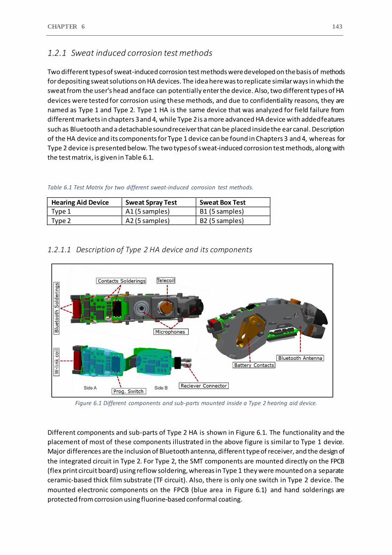
CHAPTER 6 143
1.2.1 Sweat induced corrosion test methods
Two different types of sweat-induced corrosion test methods were developed on the basis of methods
for depositing sweat solutions on HA devices. The idea here was to replicate similar ways in which the
sweat from the user's head and face can potentially enter the device. Also, two different types of HA
devices were tested for corrosion using these methods, and due to confidentiality reasons, they are
named as Type 1 and Type 2. Type 1 HA is the same device that was analyzed for field failure from
different markets in chapters 3 and 4, while Type 2 is a more advanced HA device with added features
such as Bluetooth and a detachable sound receiver that can be placed inside the ear canal. Description
of the HA device and its components for Type 1 device can be found in Chapters 3 and 4, whereas for
Type 2 device is presented below. The two types of sweat-induced corrosion test methods, along with
the test matrix, is given in Table 6.1.
Table 6.1 Test Matrix for two different sweat-induced corrosion test methods.
Hearing Aid Device Sweat Spray Test Sweat Box Test Type 1 A1 (5 samples) B1 (5 samples)
Type 2 A2 (5 samples) B2 (5 samples)
1.2.1.1 Description of Type 2 HA device and its components
Figure 6.1 Different components and sub-parts mounted inside a Type 2 hearing aid device.
Different components and sub-parts of Type 2 HA is shown in Figure 6.1. The functionality and the
placement of most of these components illustrated in the above figure is similar to Type 1 device.
Major differences are the inclusion of Bluetooth antenna, different type of receiver, and the design of
the integrated circuit in Type 2. For Type 2, the SMT components are mounted directly on the FPCB
(flex print circuit board) using reflow soldering, whereas in Type 1 they were mounted on a separate
ceramic-based thick film substrate (TF circuit). Also, there is only one switch in Type 2 device. The
mounted electronic components on the FPCB (blue area in Figure 6.1) and hand solderings are
protected from corrosion using fluorine-based conformal coating.
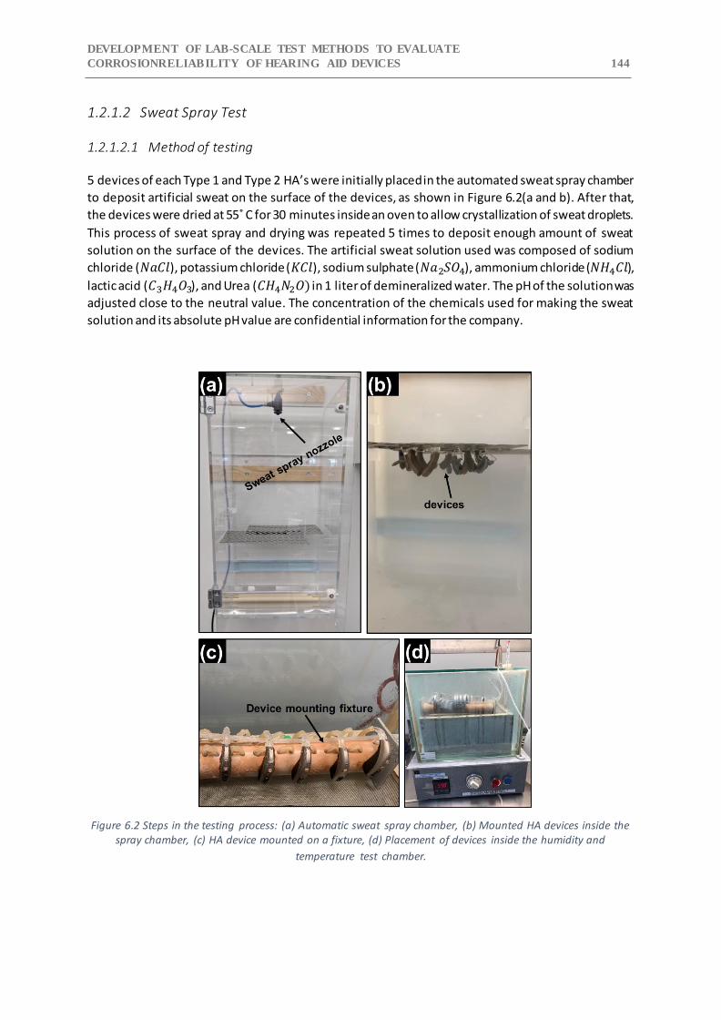
DEVELOPMENT OF LAB-SCALE TEST METHODS TO EVALUATE
CORROSIONRELIABILITY OF HEARING AID DEVICES 144
1.2.1.2 Sweat Spray Test
1.2.1.2.1 Method of testing
5 devices of each Type 1 and Type 2 HA’s were initially placed in the automated sweat spray chamber
to deposit artificial sweat on the surface of the devices, as shown in Figure 6.2(a and b). After that,
the devices were dried at 55˚ C for 30 minutes inside an oven to allow crystallization of sweat droplets.
This process of sweat spray and drying was repeated 5 times to deposit enough amount of sweat
solution on the surface of the devices. The artificial sweat solution used was composed of sodium
chloride (𝑁𝑎𝐶𝑙), potassium chloride (𝐾𝐶𝑙), sodium sulphate (𝑁𝑎2𝑆𝑂4), ammonium chloride (𝑁𝐻4𝐶𝑙),
lactic acid (𝐶3𝐻4𝑂3), and Urea (𝐶𝐻4𝑁2𝑂) in 1 liter of demineralized water. The pH of the solution was
adjusted close to the neutral value. The concentration of the chemicals used for making the sweat
solution and its absolute pH value are confidential information for the company.
Figure 6.2 Steps in the testing process: (a) Automatic sweat spray chamber, (b) Mounted HA devices inside the spray chamber, (c) HA device mounted on a fixture, (d) Placement of devices inside the humidity and
temperature test chamber.
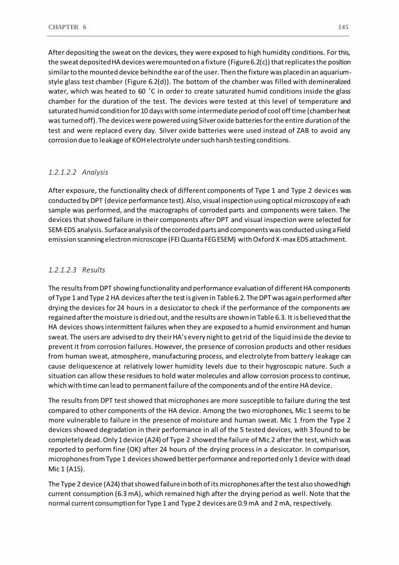
CHAPTER 6 145
After depositing the sweat on the devices, they were exposed to high humidity conditions. For this,
the sweat deposited HA devices were mounted on a fixture (Figure 6.2(c)) that replicates the position
similar to the mounted device behind the ear of the user. Then the fixture was placed in an aquarium-
style glass test chamber (Figure 6.2(d)). The bottom of the chamber was filled with demineralized
water, which was heated to 60 ˚C in order to create saturated humid conditions inside the glass
chamber for the duration of the test. The devices were tested at this level of temperature and
saturated humid condition for 10 days with some intermediate period of cool off time (chamber heat
was turned off). The devices were powered using Silver oxide batteries for the entire duration of the
test and were replaced every day. Silver oxide batteries were used instead of ZAB to avoid any
corrosion due to leakage of KOH electrolyte under such harsh testing conditions.
1.2.1.2.2 Analysis
After exposure, the functionality check of different components of Type 1 and Type 2 devices was
conducted by DPT (device performance test). Also, visual inspection using optical microscopy of each
sample was performed, and the macrographs of corroded parts and components were taken. The
devices that showed failure in their components after DPT and visual inspection were selected for
SEM-EDS analysis. Surface analysis of the corroded parts and components was conducted using a Field
emission scanning electron microscope (FEI Quanta FEG ESEM) with Oxford X-max EDS attachment.
1.2.1.2.3 Results
The results from DPT showing functionality and performance evaluation of different HA components
of Type 1 and Type 2 HA devices after the test is given in Table 6.2. The DPT was again performed after
drying the devices for 24 hours in a desiccator to check if the performance of the components are
regained after the moisture is dried out, and the results are shown in Table 6.3. It is believed that the
HA devices shows intermittent failures when they are exposed to a humid environment and human
sweat. The users are advised to dry their HA’s every night to get rid of the liquid insi de the device to
prevent it from corrosion failures. However, the presence of corrosion products and other residues
from human sweat, atmosphere, manufacturing process, and electrolyte from battery leakage can
cause deliquescence at relatively lower humidity levels due to their hygroscopic nature. Such a
situation can allow these residues to hold water molecules and allow corrosion process to continue,
which with time can lead to permanent failure of the components and of the entire HA device.
The results from DPT test showed that microphones are more susceptible to failure during the test
compared to other components of the HA device. Among the two microphones, Mic 1 seems to be
more vulnerable to failure in the presence of moisture and human sweat. Mic 1 from the Type 2
devices showed degradation in their performance in all of the 5 tested devices, with 3 found to be
completely dead. Only 1 device (A24) of Type 2 showed the failure of Mic 2 after the test, which was
reported to perform fine (OK) after 24 hours of the drying process in a desiccator. In comparison,
microphones from Type 1 devices showed better performance and reported only 1 device with dead
Mic 1 (A15).
The Type 2 device (A24) that showed failure in both of its microphones after the test also showed high
current consumption (6.3 mA), which remained high after the drying period as well. Note that the
normal current consumption for Type 1 and Type 2 devices are 0.9 mA and 2 mA, respectively.
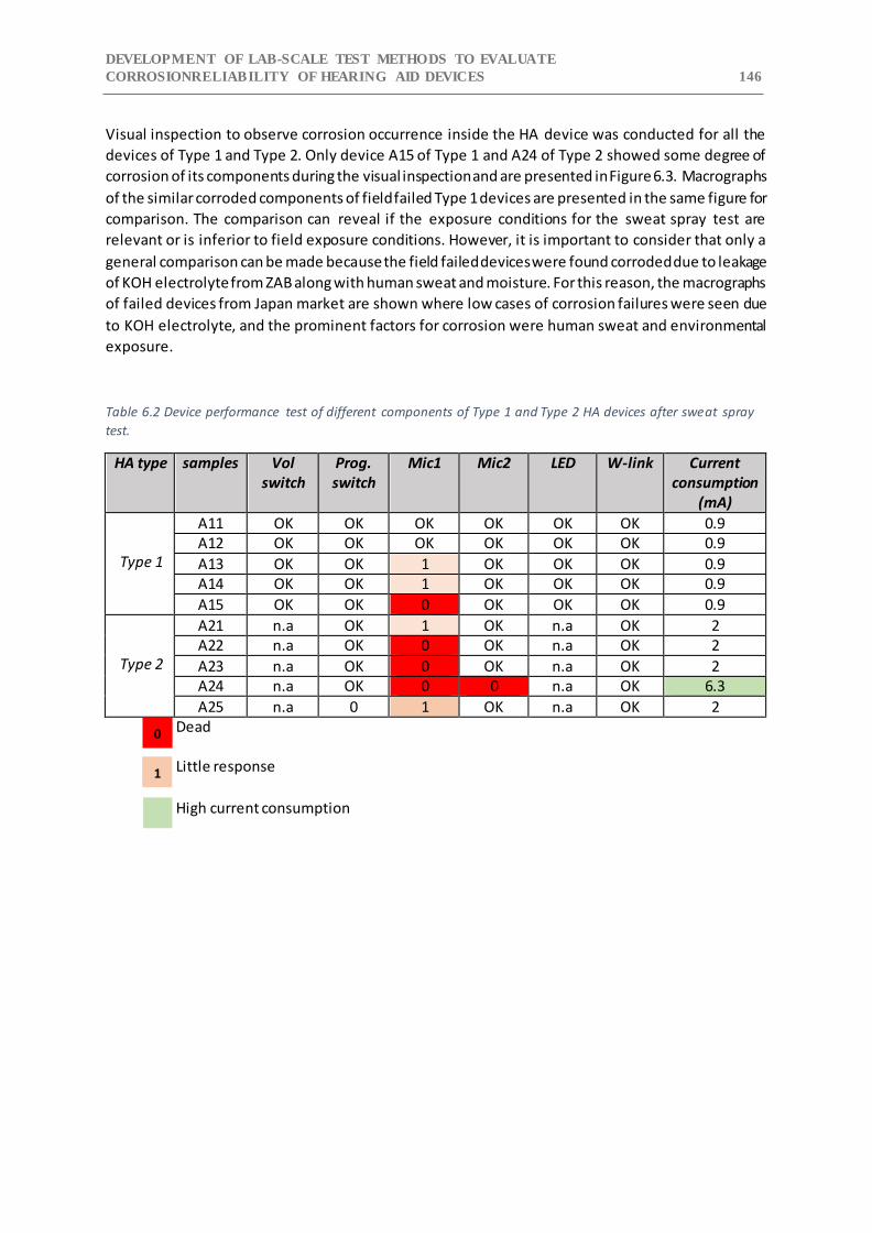
DEVELOPMENT OF LAB-SCALE TEST METHODS TO EVALUATE
CORROSIONRELIABILITY OF HEARING AID DEVICES 146
Visual inspection to observe corrosion occurrence inside the HA device was conducted for all the
devices of Type 1 and Type 2. Only device A15 of Type 1 and A24 of Type 2 showed some degree of
corrosion of its components during the visual inspection and are presented in Figure 6.3. Macrographs
of the similar corroded components of field failed Type 1 devices are presented in the same figure for
comparison. The comparison can reveal if the exposure conditions for the sweat spray test are
relevant or is inferior to field exposure conditions. However, it is important to consider that only a
general comparison can be made because the field failed devices were found corroded due to leakage
of KOH electrolyte from ZAB along with human sweat and moisture. For this reason, the macrographs
of failed devices from Japan market are shown where low cases of corrosion failures were seen due
to KOH electrolyte, and the prominent factors for corrosion were human sweat and environmental
exposure.
Table 6.2 Device performance test of different components of Type 1 and Type 2 HA devices after sweat spray
test.
HA type samples Vol switch
Prog. switch
Mic1 Mic2 LED W-link Current consumption
(mA)
Type 1
A11 OK OK OK OK OK OK 0.9 A12 OK OK OK OK OK OK 0.9
A13 OK OK 1 OK OK OK 0.9 A14 OK OK 1 OK OK OK 0.9
A15 OK OK 0 OK OK OK 0.9
Type 2
A21 n.a OK 1 OK n.a OK 2 A22 n.a OK 0 OK n.a OK 2
A23 n.a OK 0 OK n.a OK 2 A24 n.a OK 0 0 n.a OK 6.3
A25 n.a 0 1 OK n.a OK 2 Dead Little response
High current consumption
0
1
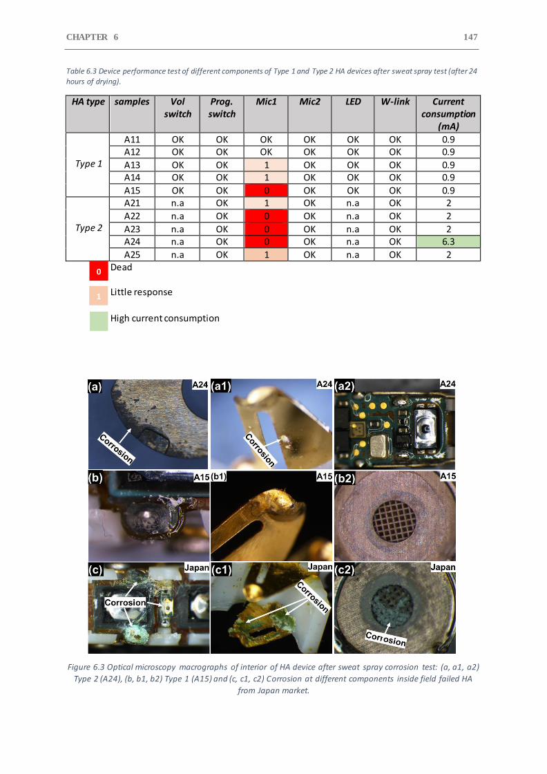
CHAPTER 6 147
Table 6.3 Device performance test of different components of Type 1 and Type 2 HA devices after sweat spray test (after 24 hours of drying).
HA type samples Vol switch
Prog. switch
Mic1 Mic2 LED W-link Current consumption
(mA)
Type 1
A11 OK OK OK OK OK OK 0.9 A12 OK OK OK OK OK OK 0.9
A13 OK OK 1 OK OK OK 0.9 A14 OK OK 1 OK OK OK 0.9
A15 OK OK 0 OK OK OK 0.9
Type 2
A21 n.a OK 1 OK n.a OK 2
A22 n.a OK 0 OK n.a OK 2
A23 n.a OK 0 OK n.a OK 2 A24 n.a OK 0 OK n.a OK 6.3
A25 n.a OK 1 OK n.a OK 2 Dead Little response
High current consumption
Figure 6.3 Optical microscopy macrographs of interior of HA device after sweat spray corrosion test: (a, a1, a2)
Type 2 (A24), (b, b1, b2) Type 1 (A15) and (c, c1, c2) Corrosion at different components inside field failed HA
from Japan market.
0
1
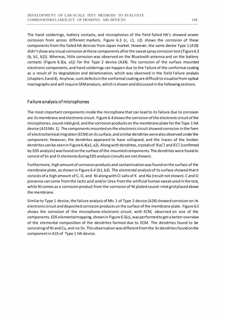
DEVELOPMENT OF LAB-SCALE TEST METHODS TO EVALUATE
CORROSIONRELIABILITY OF HEARING AID DEVICES 148
The hand solderings, battery contacts, and microphones of the field failed HA’s showed severe
corrosion from across different markets. Figure 6.3 (c, c1, c2) shows the corrosion of these
components from the failed HA devices from Japan market. However, the same device Type 1 (A15)
didn’t show any visual corrosion at these components after the sweat spray corrosion test (Figure 6.3
(b, b1, b2)). Whereas, little corrosion was observed on the Bluetooth antenna and on the battery
contacts (Figure 6.3(a, a1)) for the Type 2 device (A24). The corrosion of the surface mounted
electronic components, and hand solderings can happen due to the failure of the conformal coating
as a result of its degradation and delamination, which was observed in the field failure analysis
(chapters 3 and 4). Anyhow, such defects in the conformal coating are difficult to visualize from optical
macrographs and will require SEM analysis, which is shown and discussed in the following sections.
Failure analysis of microphones
The most important components inside the microphone that can lead to its failure due to corrosion
are its membrane and electronic circuit. Figure 6.4 shows the corrosion of the electronic circuit of the
microphones, sound-inlet grid, and the corrosion products on the membrane plate for the Type 1 HA
device (A15 Mic 1). The components mounted on the electronic circuit showed corrosion in the form
of electrochemical migration (ECM) on its surface, and similar dendrites were also observed under the
component. However, the dendrites appeared to have collapsed, and the traces of the broken
dendrites can be seen in Figure 6.4(a1, a2). Along with dendrites, crystals of 𝑁𝑎𝐶𝑙 and 𝐾𝐶𝑙 (confirmed
by EDS analysis) was found on the surface of the mounted components. The dendrites were found to
consist of Sn and O elements during EDS analysis (results are not shown).
Furthermore, high amount of corrosion products and contamination was found on the surface of the
membrane plate, as shown in Figure 6.4 (b1, b2). The elemental analysis of its surface showed that it
consists of a high amount of C, O, and Ni along with Cl salts of K and Na (result not shown). C and O
presence can come from the lactic acid and/or Urea from the artificial human sweat used in the test,
while Ni comes as a corrosion product from the corrosion of Ni plated sound-inlet grid placed above
the membrane.
Similar to Type 1 device, the failure analysis of Mic 1 of Type 2 device (A24) showed corrosion on its
electronic circuit and deposited corrosion products on the surface of the membrane plate. Figure 6.5
shows the corrosion of the microphone electronic circuit, with ECM, observed on one of the
components. EDS elemental mapping, shown in Figure 6.5(c), was performed to get a better overview
of the elemental composition of the dendrites formed due to ECM. The dendrites found to be
consisting of Ni and Cu, and no Sn. This observation was different from the Sn dendrites found on the
component in A15 of Type 1 HA device.
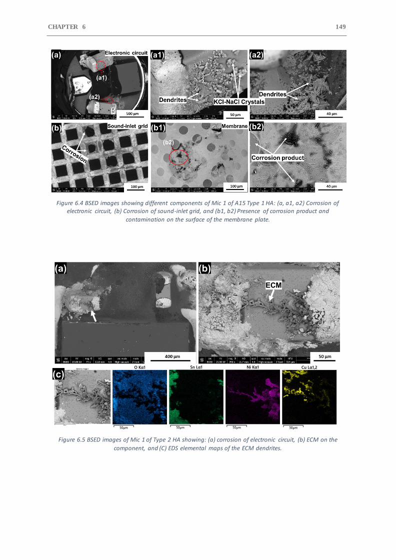
CHAPTER 6 149
Figure 6.4 BSED images showing different components of Mic 1 of A15 Type 1 HA: (a, a1, a2) Corrosion of electronic circuit, (b) Corrosion of sound-inlet grid, and (b1, b2) Presence of corrosion product and
contamination on the surface of the membrane plate.
Figure 6.5 BSED images of Mic 1 of Type 2 HA showing: (a) corrosion of electronic circuit, (b) ECM on the
component, and (C) EDS elemental maps of the ECM dendrites.
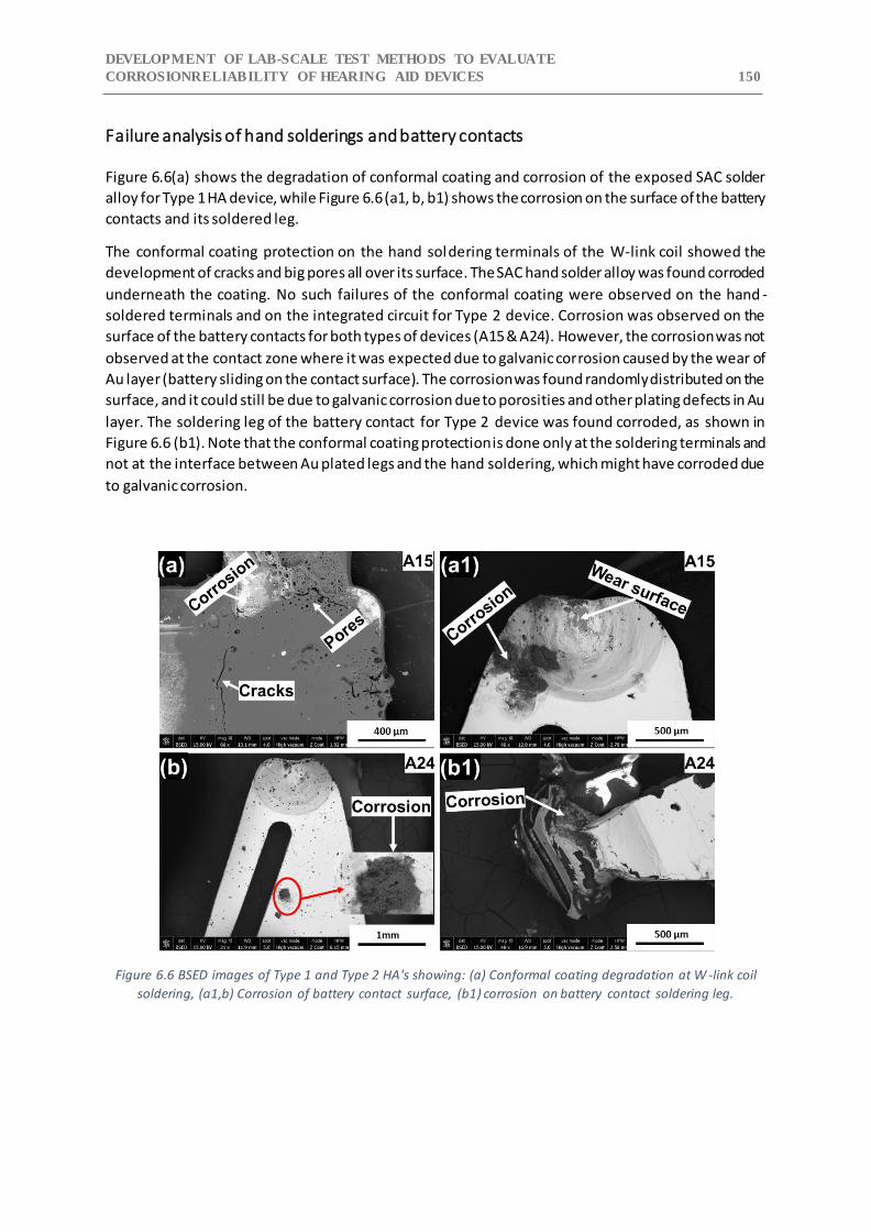
DEVELOPMENT OF LAB-SCALE TEST METHODS TO EVALUATE
CORROSIONRELIABILITY OF HEARING AID DEVICES 150
Failure analysis of hand solderings and battery contacts
Figure 6.6(a) shows the degradation of conformal coating and corrosion of the exposed SAC solder
alloy for Type 1 HA device, while Figure 6.6 (a1, b, b1) shows the corrosion on the surface of the battery
contacts and its soldered leg.
The conformal coating protection on the hand soldering terminals of the W-link coil showed the
development of cracks and big pores all over its surface. The SAC hand solder alloy was found corroded
underneath the coating. No such failures of the conformal coating were observed on the hand -
soldered terminals and on the integrated circuit for Type 2 device. Corrosion was observed on the
surface of the battery contacts for both types of devices (A15 & A24). However, the corrosion was not
observed at the contact zone where it was expected due to galvanic corrosion caused by the wear of
Au layer (battery sliding on the contact surface). The corrosion was found randomly distributed on the
surface, and it could still be due to galvanic corrosion due to porosities and other plating defects in Au
layer. The soldering leg of the battery contact for Type 2 device was found corroded, as shown in
Figure 6.6 (b1). Note that the conformal coating protection is done only at the soldering terminals and
not at the interface between Au plated legs and the hand soldering, which might have corroded due
to galvanic corrosion.
Figure 6.6 BSED images of Type 1 and Type 2 HA's showing: (a) Conformal coating degradation at W -link coil
soldering, (a1,b) Corrosion of battery contact surface, (b1) corrosion on battery contact soldering leg.
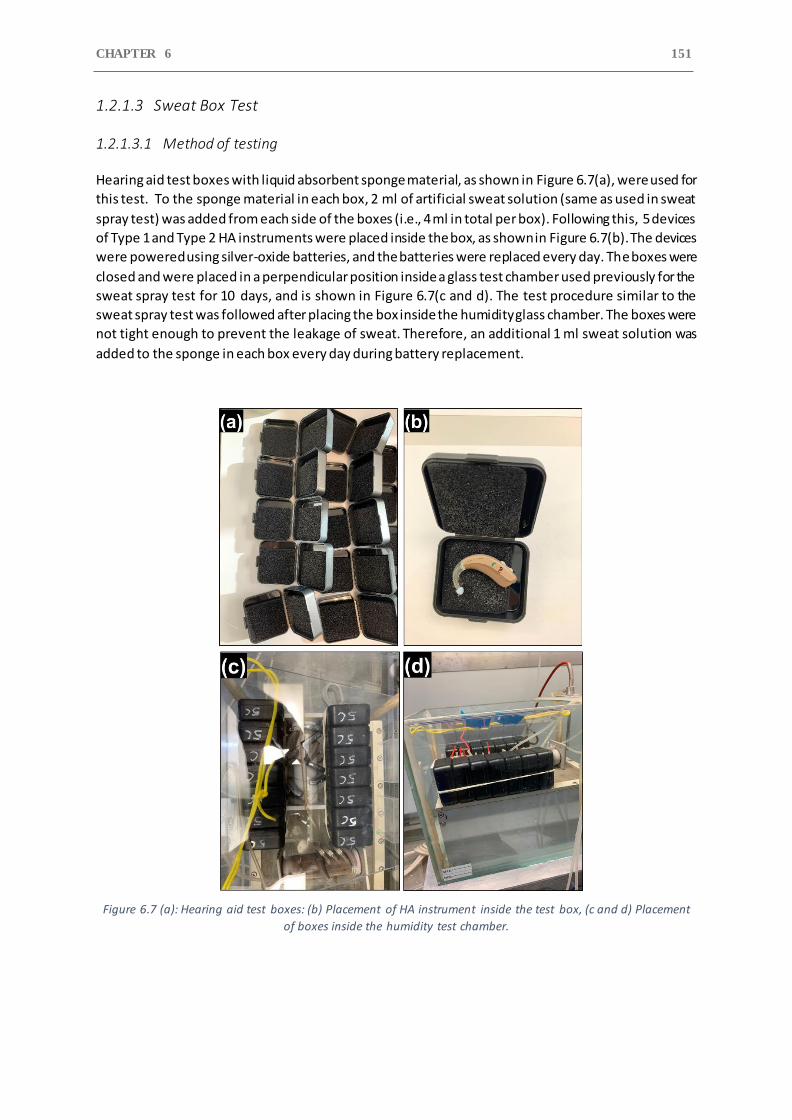
CHAPTER 6 151
1.2.1.3 Sweat Box Test
1.2.1.3.1 Method of testing
Hearing aid test boxes with liquid absorbent sponge material, as shown in Figure 6.7(a), were used for
this test. To the sponge material in each box, 2 ml of artificial sweat solution (same as used in sweat
spray test) was added from each side of the boxes (i.e., 4 ml in total per box). Following this, 5 devices
of Type 1 and Type 2 HA instruments were placed inside the box, as shown in Figure 6.7(b). The devices
were powered using silver-oxide batteries, and the batteries were replaced every day. The boxes were
closed and were placed in a perpendicular position inside a glass test chamber used previously for the
sweat spray test for 10 days, and is shown in Figure 6.7(c and d). The test procedure similar to the
sweat spray test was followed after placing the box inside the humidity glass chamber. The boxes were
not tight enough to prevent the leakage of sweat. Therefore, an additional 1 ml sweat solution was
added to the sponge in each box every day during battery replacement.
Figure 6.7 (a): Hearing aid test boxes: (b) Placement of HA instrument inside the test box, (c and d) Placement
of boxes inside the humidity test chamber.
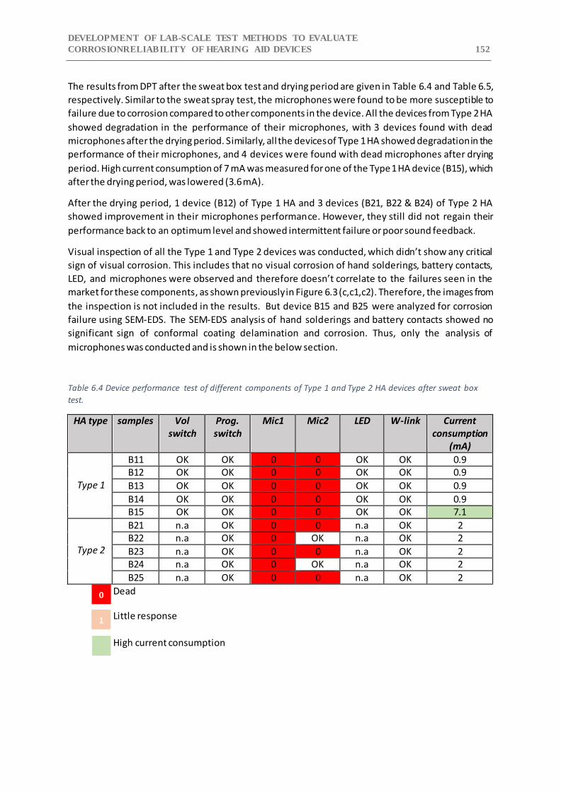
DEVELOPMENT OF LAB-SCALE TEST METHODS TO EVALUATE
CORROSIONRELIABILITY OF HEARING AID DEVICES 152
The results from DPT after the sweat box test and drying period are given in Table 6.4 and Table 6.5,
respectively. Similar to the sweat spray test, the microphones were found to be more susceptible to
failure due to corrosion compared to other components in the device. All the devices from Type 2 HA
showed degradation in the performance of their microphones, with 3 devices found with dead
microphones after the drying period. Similarly, all the devices of Type 1 HA showed degradation in the
performance of their microphones, and 4 devices were found with dead microphones after drying
period. High current consumption of 7 mA was measured for one of the Type 1 HA device (B15), which
after the drying period, was lowered (3.6 mA).
After the drying period, 1 device (B12) of Type 1 HA and 3 devices (B21, B22 & B24) of Type 2 HA
showed improvement in their microphones performance. However, they still did not regain their
performance back to an optimum level and showed intermittent failure or poor sound feedback.
Visual inspection of all the Type 1 and Type 2 devices was conducted, which didn’t show any critical
sign of visual corrosion. This includes that no visual corrosion of hand solderings, battery contacts,
LED, and microphones were observed and therefore doesn’t correlate to the failures seen in the
market for these components, as shown previously in Figure 6.3 (c,c1,c2). Therefore, the images from
the inspection is not included in the results. But device B15 and B25 were analyzed for corrosion
failure using SEM-EDS. The SEM-EDS analysis of hand solderings and battery contacts showed no
significant sign of conformal coating delamination and corrosion. Thus, only the analysis of
microphones was conducted and is shown in the below section.
Table 6.4 Device performance test of different components of Type 1 and Type 2 HA devices after sweat box
test.
HA type samples Vol switch
Prog. switch
Mic1 Mic2 LED W-link Current consumption
(mA)
Type 1
B11 OK OK 0 0 OK OK 0.9 B12 OK OK 0 0 OK OK 0.9
B13 OK OK 0 0 OK OK 0.9
B14 OK OK 0 0 OK OK 0.9 B15 OK OK 0 0 OK OK 7.1
Type 2
B21 n.a OK 0 0 n.a OK 2 B22 n.a OK 0 OK n.a OK 2
B23 n.a OK 0 0 n.a OK 2 B24 n.a OK 0 OK n.a OK 2
B25 n.a OK 0 0 n.a OK 2
Dead Little response
High current consumption
0
1
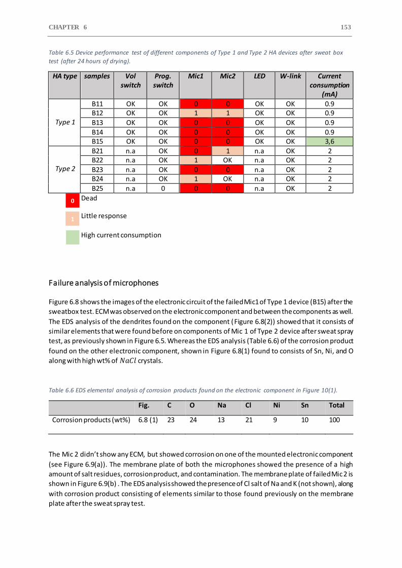
CHAPTER 6 153
Table 6.5 Device performance test of different components of Type 1 and Type 2 HA devices after sweat box
test (after 24 hours of drying).
HA type samples Vol switch
Prog. switch
Mic1 Mic2 LED W-link Current consumption
(mA)
Type 1
B11 OK OK 0 0 OK OK 0.9 B12 OK OK 1 1 OK OK 0.9
B13 OK OK 0 0 OK OK 0.9
B14 OK OK 0 0 OK OK 0.9 B15 OK OK 0 0 OK OK 3,6
Type 2
B21 n.a OK 0 1 n.a OK 2 B22 n.a OK 1 OK n.a OK 2
B23 n.a OK 0 0 n.a OK 2 B24 n.a OK 1 OK n.a OK 2
B25 n.a 0 0 0 n.a OK 2
Dead Little response
High current consumption
Failure analysis of microphones
Figure 6.8 shows the images of the electronic circuit of the failed Mic1 of Type 1 device (B15) after the
sweatbox test. ECM was observed on the electronic component and between the components as well.
The EDS analysis of the dendrites found on the component (Figure 6.8(2)) showed that it consists of
similar elements that were found before on components of Mic 1 of Type 2 device after sweat spray
test, as previously shown in Figure 6.5. Whereas the EDS analysis (Table 6.6) of the corrosion product
found on the other electronic component, shown in Figure 6.8(1) found to consists of Sn, Ni, and O
along with high wt% of 𝑁𝑎𝐶𝑙 crystals.
Table 6.6 EDS elemental analysis of corrosion products found on the electronic component in Figure 10(1).
Fig. C O Na Cl Ni Sn Total
Corrosion products (wt%) 6.8 (1) 23 24 13 21 9 10 100
The Mic 2 didn’t show any ECM, but showed corrosion on one of the mounted electronic component
(see Figure 6.9(a)). The membrane plate of both the microphones showed the presence of a high
amount of salt residues, corrosion product, and contamination. The membrane plate of failed Mic 2 is
shown in Figure 6.9(b) . The EDS analysis showed the presence of Cl salt of Na and K (not shown), along
with corrosion product consisting of elements similar to those found previously on the membrane
plate after the sweat spray test.
0
1
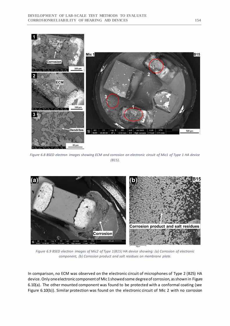
DEVELOPMENT OF LAB-SCALE TEST METHODS TO EVALUATE
CORROSIONRELIABILITY OF HEARING AID DEVICES 154
Figure 6.8 BSED electron images showing ECM and corrosion on electronic circuit of Mic1 of Type 1 HA device
(B15).
Figure 6.9 BSED electron images of Mic2 of Type 1(B15) HA device showing: (a) Corrosion of electronic
component, (b) Corrosion product and salt residues on membrane plate.
In comparison, no ECM was observed on the electronic circuit of microphones of Type 2 (B25) HA
device. Only one electronic component of Mic 1 showed some degree of corrosion, as shown in Figure
6.10(a). The other mounted component was found to be protected with a conformal coating (see
Figure 6.10(b)). Similar protection was found on the electronic circuit of Mic 2 with no corrosion
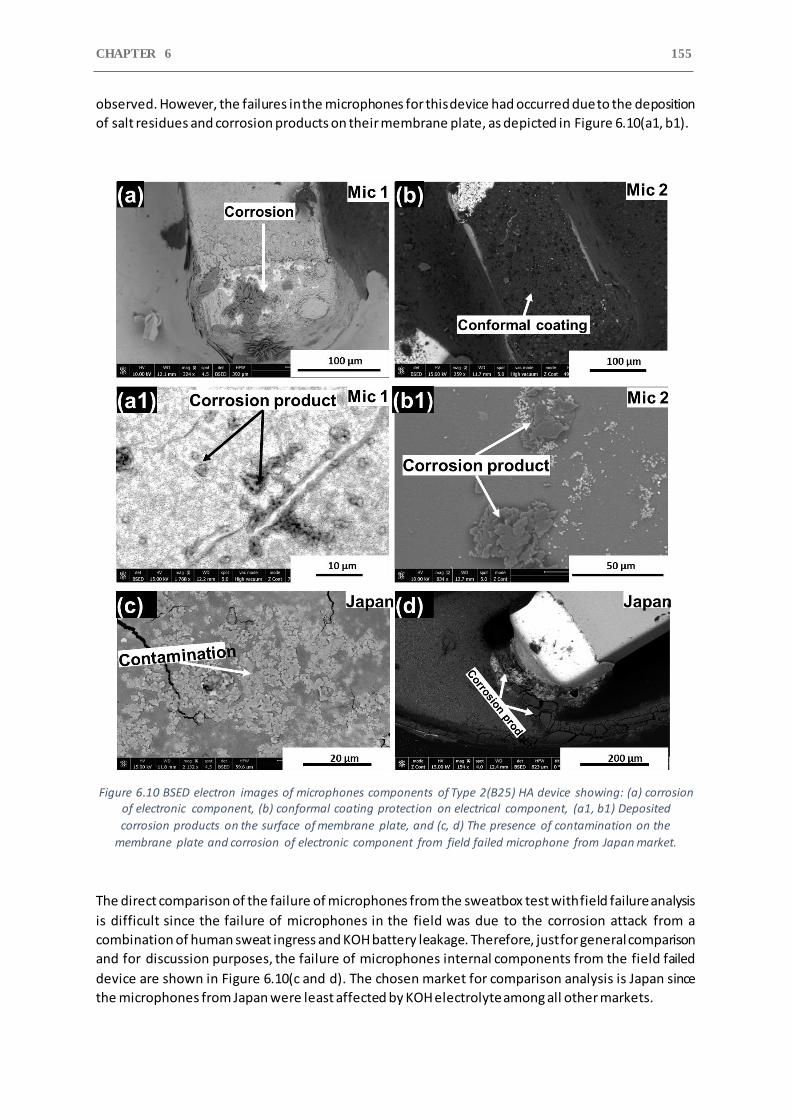
CHAPTER 6 155
observed. However, the failures in the microphones for this device had occurred due to the deposition
of salt residues and corrosion products on their membrane plate, as depicted in Figure 6.10(a1, b1).
Figure 6.10 BSED electron images of microphones components of Type 2(B25) HA device showing: (a) corrosion of electronic component, (b) conformal coating protection on electrical component, (a1, b1) Deposited
corrosion products on the surface of membrane plate, and (c, d) The presence of contamination on the
membrane plate and corrosion of electronic component from field failed microphone from Japan market.
The direct comparison of the failure of microphones from the sweatbox test with field failure analysis
is difficult since the failure of microphones in the field was due to the corrosion attack from a
combination of human sweat ingress and KOH battery leakage. Therefore, just for general comparison
and for discussion purposes, the failure of microphones internal components from the field failed
device are shown in Figure 6.10(c and d). The chosen market for comparison analysis is Japan since
the microphones from Japan were least affected by KOH electrolyte among all other markets.
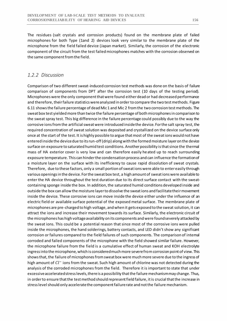
DEVELOPMENT OF LAB-SCALE TEST METHODS TO EVALUATE
CORROSIONRELIABILITY OF HEARING AID DEVICES 156
The residues (salt crystals and corrosion products) found on the membrane plate of failed
microphones for both Type (1and 2) devices look very similar to the membrane plate of the
microphone from the field failed device (Japan market). Similarly, the corrosion of the electronic
component of the circuit from the test failed microphones matches with the corrosion observed on
the same component from the field.
1.2.2 Discussion
Comparison of two different sweat-induced corrosion test methods was done on the basis of failure
comparison of components from DPT after the corrosion test (10 days of the testing period).
Microphones were the only component that were found either dead or had decreased performance
and therefore, their failure statistics were analyzed in order to compare the two test methods. Figure
6.11 shows the failure percentage of dead Mic 1 and Mic 2 from the two corrosion test methods. The
sweat box test yielded more than twice the failure percentage of both microphones in comparison to
the sweat spray test. This big difference in the failure percentage could possibly due to the way the
corrosive ions from the artificial sweat were introduced inside the device. For the salt spray test, the
required concentration of sweat solution was deposited and crystallized on the device surface only
once at the start of the test. It is highly possible to argue that most of the sweat ions would not have
entered inside the device due to its run-off (drip) along with the formed moisture layer on the device
surface on exposure to saturated humid test conditions. Another possibility is that since the thermal
mass of HA exterior cover is very low and can therefore easily he ated up to reach surrounding
exposure temperature. This can hinder the condensation process and can influence the formation of
a moisture layer on the surface with its inefficiency to cause rapid dissolution of sweat crystals.
Therefore, due to these factors, only a small portion of sweat ions were able to enter easily through
various openings in the device. For the sweat box test, a high amount of sweat ions were available to
enter the HA device throughout the test duration due to its direct surface contact with the sweat-
containing sponge inside the box. In addition, the saturated humid conditions developed inside and
outside the box can allow the moisture layer to dissolve the sweat ions and facilitate their movement
inside the device. These corrosive ions can move inside the device either under the influence of an
electric field or available surface potential of the exposed metal surface. The membrane plate of
microphones are pre-charged to high voltage, and when it gets exposed to the sweat solution, it can
attract the ions and increase their movement towards its surface. Similarly, the electronic circuit of
the microphones has high voltage availability on its components and were found severely attacked by
the sweat ions. This could be a potential reason that since most of the corrosive ions were pulled
inside the microphones, the hand solderings, battery contacts, and LED didn’t show any significant
corrosion or failures compared to the field failures of such components. The comparison of internal
corroded and failed components of the microphone with the field showed similar failure. However,
the microphone failure from the field is a cumulative effect of human sweat and KOH electrolyte
ingress into the microphone, which is considered much more severe from corrosion point of view. This
shows that, the failure of microphones from sweat box were much more severe due to the ingress of
high amount of 𝐶𝑙− ions from the sweat. Such high amount of chlorine was not detected during the
analysis of the corroded microphones from the field. Therefore it is important to state that under
excessive accelerated stress levels, there is a possibility that the failure mechanism may change. Thus,
in order to ensure that the test method should represent field failure, it is crucial that the increase in
stress level should only accelerate the component failure rate and not the failure mechanism.
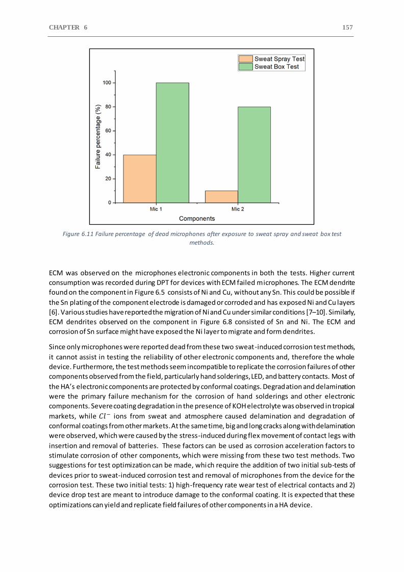
CHAPTER 6 157
Figure 6.11 Failure percentage of dead microphones after exposure to sweat spray and sweat box test
methods.
ECM was observed on the microphones electronic components in both the tests. Higher current
consumption was recorded during DPT for devices with ECM failed microphones. The ECM dendrite
found on the component in Figure 6.5 consists of Ni and Cu, without any Sn. This could be possible if
the Sn plating of the component electrode is damaged or corroded and has exposed Ni and Cu layers
[6]. Various studies have reported the migration of Ni and Cu under similar conditions [7–10]. Similarly,
ECM dendrites observed on the component in Figure 6.8 consisted of Sn and Ni. The ECM and
corrosion of Sn surface might have exposed the Ni layer to migrate and form dendrites.
Since only microphones were reported dead from these two sweat-induced corrosion test methods,
it cannot assist in testing the reliability of other electronic components and, therefore the whole
device. Furthermore, the test methods seem incompatible to replicate the corrosion failures of other
components observed from the field, particularly hand solderings, LED, and battery contacts. Most of
the HA’s electronic components are protected by conformal coatings. Degradation and delamination
were the primary failure mechanism for the corrosion of hand solderings and other electronic
components. Severe coating degradation in the presence of KOH electrolyte was observed in tropical
markets, while 𝐶𝑙− ions from sweat and atmosphere caused delamination and degradation of
conformal coatings from other markets. At the same time, big and long cracks along with delamination
were observed, which were caused by the stress-induced during flex movement of contact legs with
insertion and removal of batteries. These factors can be used as corrosion acceleration factors to
stimulate corrosion of other components, which were missing from these two test methods. Two
suggestions for test optimization can be made, which require the addition of two initial sub-tests of
devices prior to sweat-induced corrosion test and removal of microphones from the device for the
corrosion test. These two initial tests: 1) high-frequency rate wear test of electrical contacts and 2)
device drop test are meant to introduce damage to the conformal coating. It is expected that these
optimizations can yield and replicate field failures of other components in a HA device.
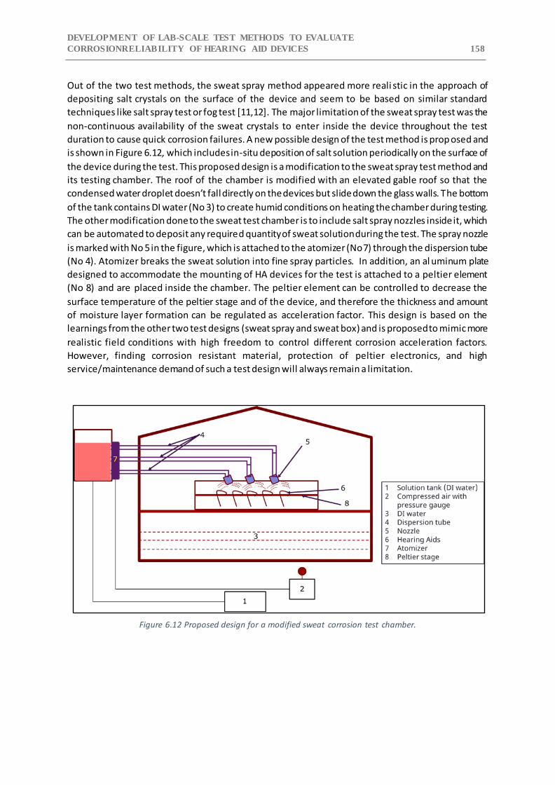
DEVELOPMENT OF LAB-SCALE TEST METHODS TO EVALUATE
CORROSIONRELIABILITY OF HEARING AID DEVICES 158
Out of the two test methods, the sweat spray method appeared more reali stic in the approach of
depositing salt crystals on the surface of the device and seem to be based on similar standard
techniques like salt spray test or fog test [11,12]. The major limitation of the sweat spray test was the
non-continuous availability of the sweat crystals to enter inside the device throughout the test
duration to cause quick corrosion failures. A new possible design of the test method is prop osed and
is shown in Figure 6.12, which includes in-situ deposition of salt solution periodically on the surface of
the device during the test. This proposed design is a modification to the sweat spray test method and
its testing chamber. The roof of the chamber is modified with an elevated gable roof so that the
condensed water droplet doesn’t fall directly on the devices but slide down the glass walls. The bottom
of the tank contains DI water (No 3) to create humid conditions on heating the chamber during testing.
The other modification done to the sweat test chamber is to include salt spray nozzles inside it, which
can be automated to deposit any required quantity of sweat solution during the test. The spray nozzle
is marked with No 5 in the figure, which is attached to the atomizer (No 7) through the dispersion tube
(No 4). Atomizer breaks the sweat solution into fine spray particles. In addition, an al uminum plate
designed to accommodate the mounting of HA devices for the test is attached to a peltier element
(No 8) and are placed inside the chamber. The peltier element can be controlled to decrease the
surface temperature of the peltier stage and of the device, and therefore the thickness and amount
of moisture layer formation can be regulated as acceleration factor. This design is based on the
learnings from the other two test designs (sweat spray and sweat box) and is proposed to mimic more
realistic field conditions with high freedom to control different corrosion acceleration factors.
However, finding corrosion resistant material, protection of peltier electronics, and high
service/maintenance demand of such a test design will always remain a limitation.
Figure 6.12 Proposed design for a modified sweat corrosion test chamber.
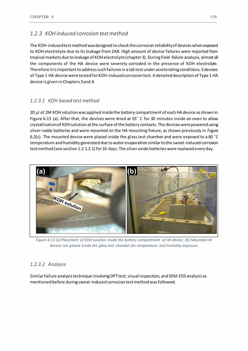
CHAPTER 6 159
1.2.3 KOH induced corrosion test method
The KOH-induced test method was designed to check the corrosion reliability of devices when exposed
to KOH electrolyte due to its leakage from ZAB. High amount of device failures were reported from
tropical markets due to leakage of KOH electrolyte (chapter 3). During field-failure analysis, almost all
the components of the HA device were severely corroded in the presence of KOH electrolyte.
Therefore it is important to address such failures in a lab test under accelerating conditions. 5 devices
of Type 1 HA device were tested for KOH-induced corrosion test. A detailed description of Type 1 HA
device is given in Chapters 3 and 4.
1.2.3.1 KOH based test method
20 μl of 2M KOH solution was applied inside the battery compartment of each HA device as shown in
Figure 6.13 (a). After that, the devices were dried at 55˚ C for 30 minutes inside an oven to allow
crystallization of KOH solution at the surface of the battery contacts. The devices were powered using
silver-oxide batteries and were mounted on the HA mounting fixture, as shown previously in Figure
6.2(c). The mounted device were placed inside the glass test chamber and were exposed to a 60 ˚C
temperature and humidity generated due to water evaporation similar to the sweat-induced corrosion
test method (see section 1.2.1.2.1) for 10 days. The silver oxide batteries were replaced every day.
Figure 6.13 (a) Placement of KOH solution inside the battery compartment of HA device, (b) Mounted HA
devices are placed inside the glass test chamber for temperature and humidity exposure.
1.2.3.2 Analysis
Similar failure analysis technique involving DPT test, visual inspection, and SEM-EDS analysis as
mentioned before during sweat-induced corrosion test method was followed.
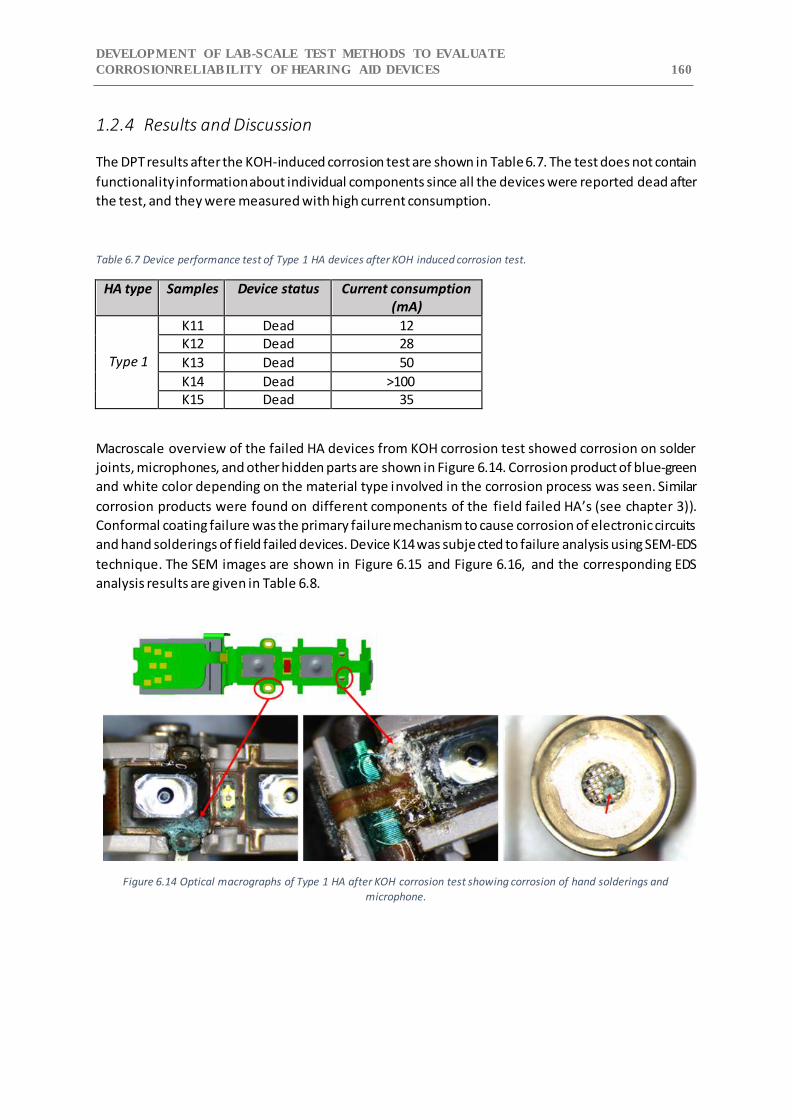
DEVELOPMENT OF LAB-SCALE TEST METHODS TO EVALUATE
CORROSIONRELIABILITY OF HEARING AID DEVICES 160
1.2.4 Results and Discussion
The DPT results after the KOH-induced corrosion test are shown in Table 6.7. The test does not contain
functionality information about individual components since all the devices were reported dead after
the test, and they were measured with high current consumption.
Table 6.7 Device performance test of Type 1 HA devices after KOH induced corrosion test.
HA type Samples Device status Current consumption (mA)
Type 1
K11 Dead 12 K12 Dead 28
K13 Dead 50
K14 Dead >100 K15 Dead 35
Macroscale overview of the failed HA devices from KOH corrosion test showed corrosion on solder
joints, microphones, and other hidden parts are shown in Figure 6.14. Corrosion product of blue-green
and white color depending on the material type involved in the corrosion process was seen. Similar
corrosion products were found on different components of the field failed HA’s (see chapter 3)).
Conformal coating failure was the primary failure mechanism to cause corrosion of electronic circuits
and hand solderings of field failed devices. Device K14 was subjected to failure analysis using SEM-EDS
technique. The SEM images are shown in Figure 6.15 and Figure 6.16, and the corresponding EDS
analysis results are given in Table 6.8.
Figure 6.14 Optical macrographs of Type 1 HA after KOH corrosion test showing corrosion of hand solderings and
microphone.
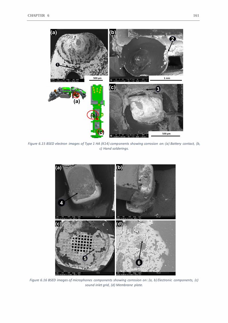
CHAPTER 6 161
Figure 6.15 BSED electron images of Type 1 HA (K14) components showing corrosion on: (a) Battery contact, (b,
c) Hand solderings.
Figure 6.16 BSED images of microphones components showing corrosion on: (a, b) Electronic components, (c)
sound inlet grid, (d) Membrane plate.
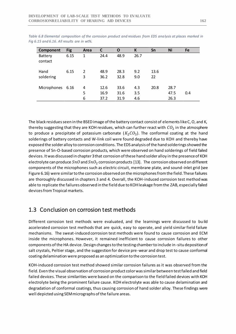
DEVELOPMENT OF LAB-SCALE TEST METHODS TO EVALUATE
CORROSIONRELIABILITY OF HEARING AID DEVICES 162
Table 6.8 Elemental composition of the corrosion product and residues from EDS analysis at places marked in
Fig 6.15 and 6.16. All results are in wt%.
Component Fig Area C O K Sn Ni Fe
Battery contact
6.15 1 24.4 48.9 26.7
Hand soldering
6.15 2 48.9 28.3 9.2 13.6 3 36.2 32.8 9.0 22
Microphones 6.16 4 12.6 33.6 4.3 20.8 28.7 5 16.9 31.6 3.5 47.5 0.4 6 37.2 31.9 4.6 26.3
The black residues seen in the BSED image of the battery contact consist of elements like C, O, and K,
thereby suggesting that they are KOH residues, which can further react with 𝐶𝑂2 in the atmosphere
to produce a precipitate of potassium carbonate (𝐾2𝐶𝑂3). The conformal coating at the hand
solderings of battery contacts and W-link coil were found degraded due to KOH and thereby have
exposed the solder alloy to corrosion conditions. The EDS analysis of the hand solderings showed the
presence of Sn-O-based corrosion products, which were observed on hand solderings of field failed
devices. It was discussed in chapter 3 that corrosion of these hand solder alloy in the presence of KOH
electrolyte can produce 𝑆𝑛𝑂 and 𝑆𝑛𝑂2 corrosion products [13]. The corrosion observed on different
components of the microphones such as electric circuit, membrane plate, and sound-inlet grid (see
Figure 6.16) were similar to the corrosion observed on the microphones from the field. These failures
are thoroughly discussed in chapters 3 and 4. Overall, the KOH-induced corrosion test method was
able to replicate the failures observed in the field due to KOH leakage from the ZAB, especially failed
devices from Tropical markets.
1.3 Conclusion on corrosion test methods
Different corrosion test methods were evaluated, and the learnings were discussed to bu ild
accelerated corrosion test methods that are quick, easy to operate, and yield similar field failure
mechanisms. The sweat-induced corrosion test methods were found to cause corrosion and ECM
inside the microphones. However, it remained inefficient to cause corrosion failures to other
components of the HA device. Design changes to the testing chamber to include in-situ deposition of
salt crystals, Peltier stage, and the suggestion for device pre-wear and drop test to cause conformal
coating delamination were proposed as an optimization to the corrosion test.
KOH-induced corrosion test method showed similar corrosion failures as it was observed from the
field. Even the visual observation of corrosion product color was similar between test failed and field
failed devices. These similarities were based on the comparison to the field failed devices with KOH
electrolyte being the prominent failure cause. KOH electrolyte was able to cause delamination and
degradation of conformal coatings, thus causing corrosion of hand solder alloy. These findings were
well depicted using SEM micrographs of the failure areas.
CHAPTER 6 163
References
[1] M. White, J.B. Bernstein, Microelectronics reliability: physics-of-failure based modeling and lifetime evaluation, JPL Publ. (2008). https://doi.org/http://hdl.handle.net/2014/40791.
[2] Physics of Failure Reliability Predictions, VMEbus International Trade Association, Standard ANSI/VITA 51.2, 2011.
[3] G. Deng, J. Qiu, G. Liu, K. Lv, Environmental stress level evaluation approach based on physical model and interval grey association degree, Chinese J. Aeronaut. 26 (2013) 456–462. https://doi.org/10.1016/J.CJA.2013.02.024.
[4] C.M. Tan, P. Singh, Time evolution degradation physics in high power whi te LEDs under high temperature-humidity conditions, IEEE Trans. Device Mater. Reliab. 14 (2014). https://doi.org/10.1109/TDMR.2014.2318725.
[5] D. Sen Li, Z.X. Lu, N. Jiang, D.N. Fang, High strain rate behavior and failure mechanism of three-dimensional five-directional carbon/phenolic braided composites under transverse compression, Compos. Part B Eng. 42 (2011). https://doi.org/10.1016/j.compositesb.2010.11.011.
[6] D. Minzari, M.S. Jellesen, P. Moller, P. Wahlberg, R. Ambat, Electrochemical migration on electronic chip resistors in chloride environments, IEEE Trans. Device Mater. Reliab. 9 (2009) 392–402. https://doi.org/10.1109/TDMR.2009.2022631.
[7] O. Devos, C. Gabrielli, L. Beitone, C. Mace, E. Ostermann, H. Perrot, Growth of electrolytic copper dendrites. II: Oxalic acid medium, J. Electroanal. Chem. 606 (2007). https://doi.org/10.1016/j.jelechem.2007.05.003.
[8] S.L. Meilink, M. Zamanzadeh, G.W. Warren, P. Wynblatt, MODELING THE FAILURE OF ELECTRONIC DEVICES BY DENDRITE GROWTH IN BULK AND THIN LAYER ELECTROLYTES., Corrosion. 44 (1988). https://doi.org/10.5006/1.3584978.
[9] G. Harsanyi, Electrochemical Processes Resulting in Migrated Short Failures in Microcircuits, IEEE Trans. Components Packag. Manuf. Technol. Part A. 18 (1995). https://doi.org/10.1109/95.465159.
[10] B.I. Noh, J.B. Lee, S.B. Jung, Effect of surface finish material on printed circuit board for electrochemical migration, Microelectron. Reliab. 48 (2008). https://doi.org/10.1016/j.microrel.2007.09.006.
[11] American Society for Testing Material, ASTM-B117-16: Standard Practice for Operating Salt Spray ( Fog ) Apparatus, ASTM Int. (2017).
[12] J. Kiilunen, L. Frisk, Reliability testing of frequency converters with salt spray and temperature humidity tests, in: 2009 Eur. Microelectron. Packag. Conf. EMPC 2009, 2009.
[13] M.C. Liew, I. Ahmad, L.M. Lee, M.F.M. Nazeri, H. Haliman, A.A. Mohamad, Corrosion behavior of Sn-3.0Ag-0.5Cu lead-free solder in potassium hydroxide electrolyte, Metall. Mater. Trans. A Phys. Metall. Mater. Sci. (2012). https://doi.org/10.1007/s11661-012-1194-5.
CHAPTER 7: PERFORMANCE EVALUATION OF CONFORMAL COATINGS UNDER
CYCLIC CLIMATIC AND FIELD EXPOSURE CONDITIONS 164
7 Performance evaluation of conformal coatings under
cyclic climatic and field exposure conditions
1.1 Introduction
Corrosion reliability of hearing aid (HA) devices and their components is a serious concern due to their
exposure to human sweat and the prevalent harsh climatic conditions in tropical, sub-tropical, and
coastal areas. Such climatic conditions can cause a rapid build-up of moisture layer on the electronic
parts and can increase the human perspiration rate, thereby accelerating the corrosion process. The
continuous design miniaturization trends in hearing aids are additional factors that reduces their
corrosion reliability due to reduced spacing between electronic components and increased electric
field. Conformal coatings are applied to various hearing aid components to protect them from
moisture, human sweat, dust, external contaminants, thereby expected to increase electronics
corrosion reliability. Generally, the conformal coatings that are used for the corrosion protection of
electronics are synthetic resins or polymers belonging to acrylic, epoxy, urethane, silicone, and
parylene chemistries [1]. Their performance depends upon various factors such as coating thickness,
conformity, moisture permeability, adhesion to print circuit board (PCB), and board surface
cleanliness [2–4]. Poor adhesion of a conformal coating to the surface is considered as one of the
major failure causes, which can allow thin electrolyte layer formation at the coating-substrate
interface leading to leak current or other corrosion phenomena’s [5,6]. Process-related contamination
such as flux residues from the soldering process, etching medium, plating bath residues, or additives
from the polymeric materials could be left on the surface of the PCB in the form of original chemicals
or decomposed fraction of compounds. Some studies in the past have shown that the presence of
flux residues beneath the coating can cause blistering and reduction in the adhesion strength of
conformal coatings under humid conditions [2,3,7]. Such conditions will lead to electrochemical
migration failures of the conformal-coated electrical components.
The predominant mechanism found for the corrosion failure of various HA components from different
markets was delamination and degradation of conformal coatings, as discussed in chapters 3 and 4.
The failure of coating occurred due to a combination of factors such as the presence of solder flux,
stress caused due to micromovements, and KOH electrolyte leakage from Zinc-air battery (ZAB). These
factors created cracks in the coating surface and led to the adhesion loss at the interface, which
allowed corrosive media to gain access to the electrical components and caused severe corrosion
attacks. A high failure percentage of hand solderings and TF circuit components of HA device were
observed as a result. Therefore, to improve HA devices corrosion reliability, it is important to evaluate
the performance of conformal coating candidates using test methods that incorporate the failure
factors and service conditions.
Various studies in the past have tested the performance of conformal coating by using surface
insulation resistance (SIR) patterns (interdigitated lines) of standard PCB test boards such as IPC- 9201
and IPC-B-25 [8,9]. However, these test PCB boards are not ideal for representing the flex print circuit
board (FPCB) of a HA device and its associated process parameters, which can directly influence the
corrosion issues and the failure of conformal coatings. The actual FPCB (flex print circuit board) of a
HA device is too complex for a basic investigation of conformal coating performance. Therefore, a
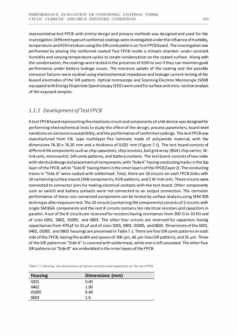
PERFORMANCE EVALUATION OF CONFORMAL COATINGS UNDER
CYCLIC CLIMATIC AND FIELD EXPOSURE CONDITIONS 165
representative test FPCB with similar design and process methods was designed and used for the
investigation. Different types of conformal coatings were investigated under the influence of humidity,
temperature and KOH residues using the SIR comb pattern on Test FPCB board. The investigation was
performed by placing the conformal-coated Test FPCB inside a climatic chamber under constant
humidity and varying temperature cycles to create condensation on the coated surface. Along with
the condensation, the coatings were tested in the presence of KOH to see if they can maintain good
performance under battery leakage issues. The moisture uptake of the coating and the possible
corrosion failures were studied using electrochemical impedance and leakage current testing of the
biased electrodes of the SIR pattern. Optical microscope and Scanning Electron Microscope (SEM)
equipped with Energy Dispersive Spectroscopy (EDS) were used for surface and cross-section analysis
of the exposed samples.
1.1.1 Development of Test FPCB
A test FPCB board representing the electronic circuit and components of a HA device was designed for
performing electrochemical tests to study the effect of the design, process parameters, board-level
variations on corrosion susceptibility, and the performance of conformal coatings. The test FPCB was
manufactured from F4L type multilayer flex laminate made of polyamide material, with the
dimensions 76.20 x 76.20 mm and a thickness of 0.025 mm (Figure 7.1). The test board consists of
different HA components such as chip capacitors, chip resistors, ball grid array (BGA) chip carrier, W-
link coils, microswitch, SIR comb patterns, and battery contacts. The test board consists of two sides
with identical design and placement of components, with “Side A” having conducting tracks i n the top
layer of the FPCB, while “Side B” having them in the inner layers of the FPCB (layer 2). The conducting
traces in “Side A” were coated with soldermask. Total, there are 16 circuits on each FPCB Sides with
10 containing surface mount (SM) components, 4 SIR patterns, and 2 W-link coils. These circuits were
connected to connector pins for making electrical contacts with the test board. Other components
such as switch and battery contacts were not connected to an output connection. The corrosion
performance of these non-connected components can be tested by surface analysis using SEM-EDS
technique after exposure test. The 10 circuits (containing SM components) consists of 2 circuits with
single SM BGA components and the rest 8 circuits contains ten identical resistors and capacitors in
parallel. 4 out of the 8 circuits are reserved for resistors having resistances from 200 Ω to 10 KΩ and
of sizes 0201, 0402, 01005, and 0603. The other four circuits are reserved for capacitors having
capacitances from 470 pF to 10 μF and of sizes 0201, 0402, 01005, and 0603. Dimensions of the 0201,
0402, 01005, and 0603 housings are presented in Table 7.1. There are four SIR comb patterns on each
side of the FPCB, having the width and spaces of 100 μm, 66 μm (two SIR pattern), and 35 μm. Three
of the SIR pattern on “Side A” is covered with soldermask, while one is left uncoated. The other four
SIR patterns on “Side B” are embedded in the inner layers of the FPCB.
Table 7.1 Housing size dimensions of various resistors and capacitors on the test FPCB.
Housing Dimensions (mm) 0201 0.60 0402 1.00 01005 0.40 0603 1.6
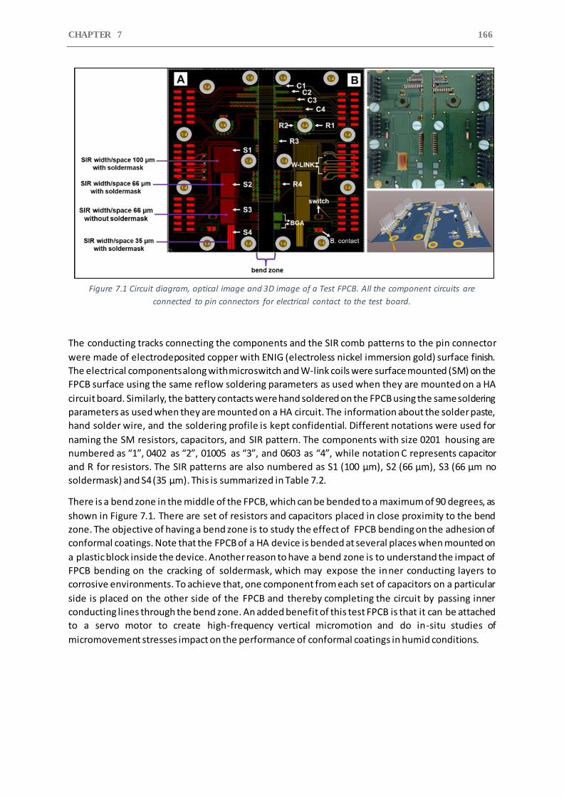
CHAPTER 7 166
Figure 7.1 Circuit diagram, optical image and 3D image of a Test FPCB. All the component circuits are
connected to pin connectors for electrical contact to the test board.
The conducting tracks connecting the components and the SIR comb patterns to the pin connector
were made of electrodeposited copper with ENIG (electroless nickel immersion gold) surface finish.
The electrical components along with microswitch and W-link coils were surface mounted (SM) on the
FPCB surface using the same reflow soldering parameters as used when they are mounted on a HA
circuit board. Similarly, the battery contacts were hand soldered on the FPCB using the same soldering
parameters as used when they are mounted on a HA circuit. The information about the solder paste,
hand solder wire, and the soldering profile is kept confidential. Different notations were used for
naming the SM resistors, capacitors, and SIR pattern. The components with size 0201 housing are
numbered as “1”, 0402 as “2”, 01005 as “3”, and 0603 as “4”, while notation C represents capacitor
and R for resistors. The SIR patterns are also numbered as S1 (100 μm), S2 (66 μm), S3 (66 μm no
soldermask) and S4 (35 μm). This is summarized in Table 7.2.
There is a bend zone in the middle of the FPCB, which can be bended to a maximum of 90 degrees, as
shown in Figure 7.1. There are set of resistors and capacitors placed in close proximity to the bend
zone. The objective of having a bend zone is to study the effect of FPCB bending on the adhesion of
conformal coatings. Note that the FPCB of a HA device is bended at several places when mounted on
a plastic block inside the device. Another reason to have a bend zone is to understand the impact of
FPCB bending on the cracking of soldermask, which may expose the inner conducting layers to
corrosive environments. To achieve that, one component from each set of capacitors on a particular
side is placed on the other side of the FPCB and thereby completing the circuit by passing inner
conducting lines through the bend zone. An added benefit of this test FPCB is that it can be attached
to a servo motor to create high-frequency vertical micromotion and do in-situ studies of
micromovement stresses impact on the performance of conformal coatings in humid conditions.
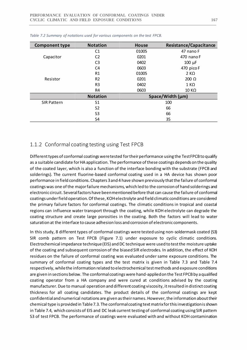
PERFORMANCE EVALUATION OF CONFORMAL COATINGS UNDER
CYCLIC CLIMATIC AND FIELD EXPOSURE CONDITIONS 167
Table 7.2 Summary of notations used for various components on the test FPCB.
Component type Notation House Resistance/Capacitance
Capacitor C1 01005 47 nano F C2 0201 470 nano F C3 0402 100 μF C4 0603 470 pico F
Resistor
R1 01005 2 KΩ R2 0201 200 Ω R3 0402 1 KΩ R4 0603 10 KΩ
Notation Space/Width (μm) SIR Pattern S1 100
66 66 35
S2 S3 S4
1.1.2 Conformal coating testing using Test FPCB
Different types of conformal coatings were tested for their performance using the Test FPCB to qualify
as a suitable candidate for HA application. The performance of these coatings depends on the quality
of the coated layer, which is also a function of the interface bonding with the substrate (FPCB and
solderings). The current fluorine-based conformal coating used in a HA device has shown poor
performance in field conditions. Chapters 3 and 4 have shown previously that the failure of conformal
coatings was one of the major failure mechanisms, which led to the corrosion of hand solderings and
electronic circuit. Several factors have been mentioned before that can cause the failure of conformal
coatings under field operation. Of these, KOH electrolyte and field climatic conditions are considered
the primary failure factors for conformal coatings. The climatic conditions in tropical and coastal
regions can influence water transport through the coating, while KOH electrolyte can degrade the
coating structure and create large porosities in the coating. Both the factors will lead to water
saturation at the interface to cause adhesion loss and corrosion of electronic components.
In this study, 8 different types of conformal coatings were tested using non-soldermask coated (S3)
SIR comb pattern on Test FPCB (Figure 7.1) under exposure to cyclic climatic conditions.
Electrochemical impedance technique (EIS) and DC technique were used to test the moisture uptake
of the coating and subsequent corrosion of the biased SIR electrodes. In addition, the effect of KOH
residues on the failure of conformal coating was evaluated under same exposure conditions. The
summary of conformal coating types and the test matrix is given in Table 7.3 and Table 7.4
respectively, while the information related to electrochemical test methods and exposure conditions
are given in sections below. The conformal coatings were hand-applied on the Test FPCB by a qualified
coating operator from a HA company and were cured at conditions advised by the coating
manufacturer. Due to manual operation and different coating viscosity, it resulted in distinct coating
thickness for all coating candidates. The product details of the conformal coatings are kept
confidential and numerical notations are given as their names. However, the information about their
chemical type is provided in Table 7.3. The conformal coating text matrix for this investigation is shown
in Table 7.4, which consists of EIS and DC leak current testing of conformal coating using SIR pattern
S3 of test FPCB. The performance of coatings were evaluated with and without KOH contamination
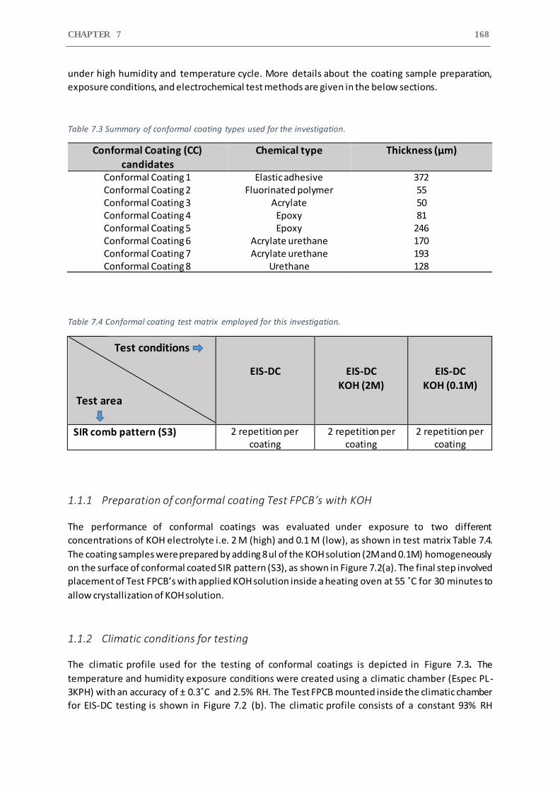
CHAPTER 7 168
under high humidity and temperature cycle. More details about the coating sample preparation,
exposure conditions, and electrochemical test methods are given in the below sections.
Table 7.3 Summary of conformal coating types used for the investigation.
Conformal Coating (CC) candidates
Chemical type Thickness (μm)
Conformal Coating 1 Elastic adhesive 372 Conformal Coating 2 Fluorinated polymer 55 Conformal Coating 3 Acrylate 50 Conformal Coating 4 Epoxy 81 Conformal Coating 5 Epoxy 246 Conformal Coating 6 Acrylate urethane 170 Conformal Coating 7 Acrylate urethane 193 Conformal Coating 8 Urethane 128
Table 7.4 Conformal coating test matrix employed for this investigation.
EIS-DC
EIS-DC
KOH (2M)
EIS-DC
KOH (0.1M)
SIR comb pattern (S3) 2 repetition per coating
2 repetition per coating
2 repetition per coating
1.1.1 Preparation of conformal coating Test FPCB’s with KOH
The performance of conformal coatings was evaluated under exposure to two different
concentrations of KOH electrolyte i.e. 2 M (high) and 0.1 M (low), as shown in test matrix Table 7.4.
The coating samples were prepared by adding 8 ul of the KOH solution (2M and 0.1M) homogeneously
on the surface of conformal coated SIR pattern (S3), as shown in Figure 7.2(a). The final step involved
placement of Test FPCB’s with applied KOH solution inside a heating oven at 55 ˚C for 30 minutes to
allow crystallization of KOH solution.
1.1.2 Climatic conditions for testing
The climatic profile used for the testing of conformal coatings is depicted in Figure 7.3. The
temperature and humidity exposure conditions were created using a climatic chamber (Espec PL-
3KPH) with an accuracy of ± 0.3˚C and 2.5% RH. The Test FPCB mounted inside the climatic chamber
for EIS-DC testing is shown in Figure 7.2 (b). The climatic profile consists of a constant 93% RH
Test area
Test conditions
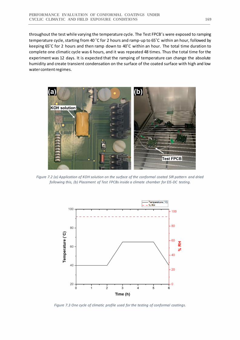
PERFORMANCE EVALUATION OF CONFORMAL COATINGS UNDER
CYCLIC CLIMATIC AND FIELD EXPOSURE CONDITIONS 169
throughout the test while varying the temperature cycle. The Test FPCB’s were exposed to ramping
temperature cycle, starting from 40 ˚C for 2 hours and ramp-up to 65˚C within an hour, followed by
keeping 65˚C for 2 hours and then ramp down to 40˚C within an hour. The total time duration to
complete one climatic cycle was 6 hours, and it was repeated 48 times. Thus the total time for the
experiment was 12 days. It is expected that the ramping of temperature can change the absolute
humidity and create transient condensation on the surface of the coated surface with high and low
water content regimes.
Figure 7.2 (a) Application of KOH solution on the surface of the conformal coated SIR pattern and dried
following this, (b) Placement of Test FPCBs inside a climate chamber for EIS-DC testing.
Figure 7.3 One cycle of climatic profile used for the testing of conformal coatings.
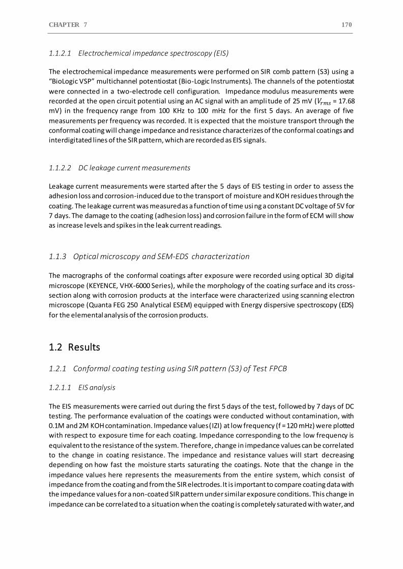
CHAPTER 7 170
1.1.2.1 Electrochemical impedance spectroscopy (EIS)
The electrochemical impedance measurements were performed on SIR comb pattern (S3) using a
“BioLogic VSP” multichannel potentiostat (Bio-Logic Instruments). The channels of the potentiostat
were connected in a two-electrode cell configuration. Impedance modulus measurements were
recorded at the open circuit potential using an AC signal with an ampli tude of 25 mV (𝑉𝑟𝑚𝑠 = 17.68
mV) in the frequency range from 100 KHz to 100 mHz for the first 5 days. An average of five
measurements per frequency was recorded. It is expected that the moisture transport through the
conformal coating will change impedance and resistance characterizes of the conformal coatings and
interdigitated lines of the SIR pattern, which are recorded as EIS signals.
1.1.2.2 DC leakage current measurements
Leakage current measurements were started after the 5 days of EIS testing in order to assess the
adhesion loss and corrosion-induced due to the transport of moisture and KOH residues through the
coating. The leakage current was measured as a function of time using a constant DC voltage of 5V for
7 days. The damage to the coating (adhesion loss) and corrosion failure in the form of ECM will show
as increase levels and spikes in the leak current readings.
1.1.3 Optical microscopy and SEM-EDS characterization
The macrographs of the conformal coatings after exposure were recorded using optical 3D digital
microscope (KEYENCE, VHX-6000 Series), while the morphology of the coating surface and its cross-
section along with corrosion products at the interface were characterized using scanning electron
microscope (Quanta FEG 250 Analytical ESEM) equipped with Energy dispersive spectroscopy (EDS)
for the elemental analysis of the corrosion products.
1.2 Results
1.2.1 Conformal coating testing using SIR pattern (S3) of Test FPCB
1.2.1.1 EIS analysis
The EIS measurements were carried out during the first 5 days of the test, followed by 7 days of DC
testing. The performance evaluation of the coatings were conducted without contamination, with
0.1M and 2M KOH contamination. Impedance values ( ꓲZꓲ) at low frequency (f = 120 mHz) were plotted
with respect to exposure time for each coating. Impedance corresponding to the low frequency is
equivalent to the resistance of the system. Therefore, change in impedance values can be correlated
to the change in coating resistance. The impedance and resistance values will start decreasing
depending on how fast the moisture starts saturating the coatings. Note that the change in the
impedance values here represents the measurements from the entire system, which consist of
impedance from the coating and from the SIR electrodes. It is important to compare coating data with
the impedance values for a non-coated SIR pattern under similar exposure conditions. This change in
impedance can be correlated to a situation when the coating is completely saturated with water, and
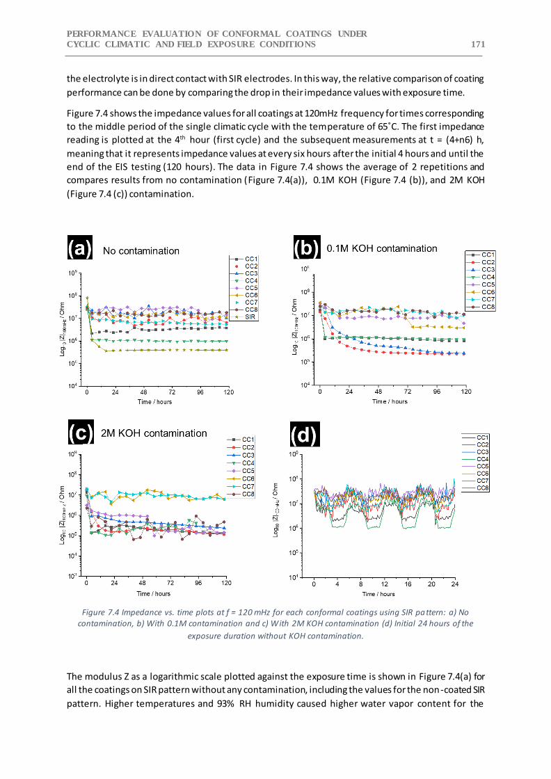
PERFORMANCE EVALUATION OF CONFORMAL COATINGS UNDER
CYCLIC CLIMATIC AND FIELD EXPOSURE CONDITIONS 171
the electrolyte is in direct contact with SIR electrodes. In this way, the relative comparison of coating
performance can be done by comparing the drop in their impedance values with exposure time.
Figure 7.4 shows the impedance values for all coatings at 120mHz frequency for times corresponding
to the middle period of the single climatic cycle with the temperature of 65˚C. The first impedance
reading is plotted at the 4th hour (first cycle) and the subsequent measurements at t = (4+n6) h,
meaning that it represents impedance values at every six hours after the initial 4 hours and until the
end of the EIS testing (120 hours). The data in Figure 7.4 shows the average of 2 repetitions and
compares results from no contamination (Figure 7.4(a)), 0.1M KOH (Figure 7.4 (b)), and 2M KOH
(Figure 7.4 (c)) contamination.
Figure 7.4 Impedance vs. time plots at f = 120 mHz for each conformal coatings using SIR pattern: a) No
contamination, b) With 0.1M contamination and c) With 2M KOH contamination (d) Initial 24 hours of the
exposure duration without KOH contamination.
The modulus Z as a logarithmic scale plotted against the exposure time is shown in Figure 7.4(a) for
all the coatings on SIR pattern without any contamination, including the values for the non-coated SIR
pattern. Higher temperatures and 93% RH humidity caused higher water vapor content for the
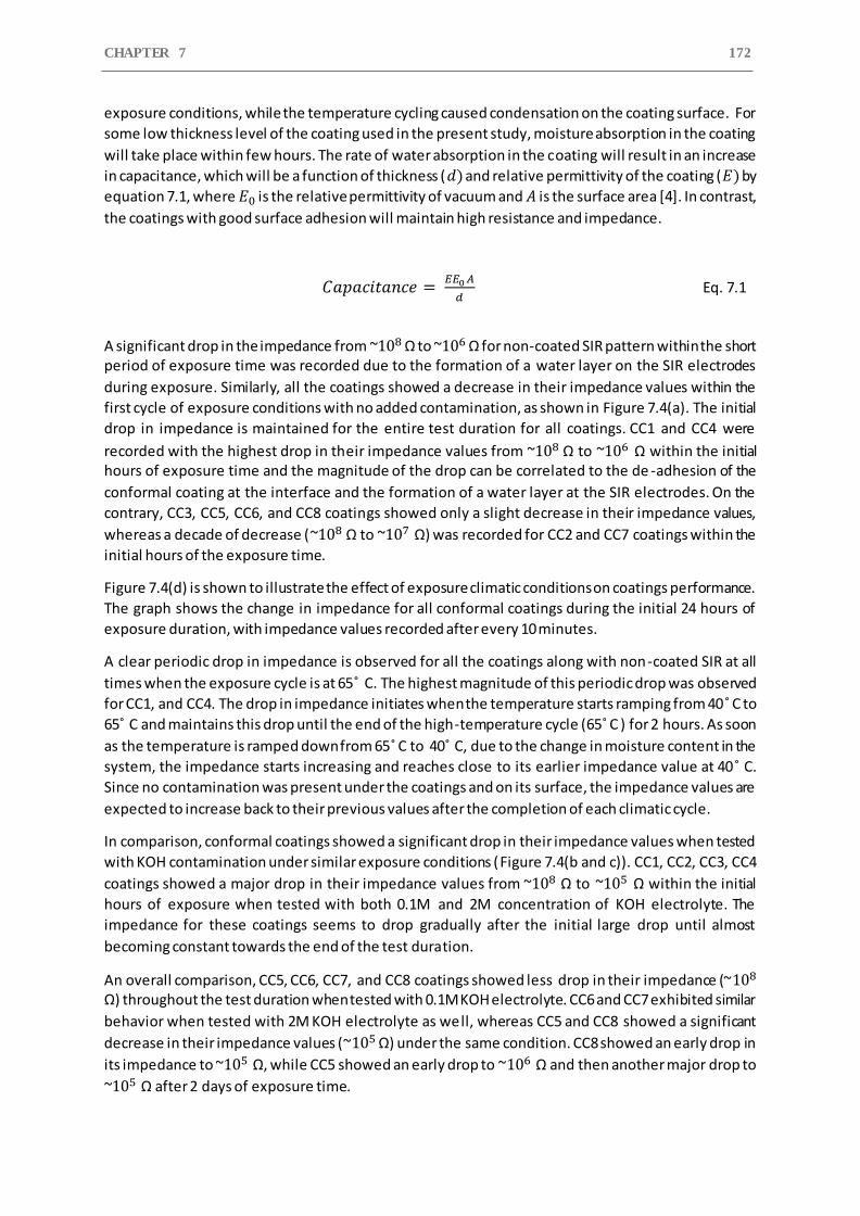
CHAPTER 7 172
exposure conditions, while the temperature cycling caused condensation on the coating surface. For
some low thickness level of the coating used in the present study, moisture absorption in the coating
will take place within few hours. The rate of water absorption in the coating will result in an increase
in capacitance, which will be a function of thickness (𝑑) and relative permittivity of the coating (𝐸) by
equation 7.1, where 𝐸0 is the relative permittivity of vacuum and 𝐴 is the surface area [4]. In contrast,
the coatings with good surface adhesion will maintain high resistance and impedance.
𝐶𝑎𝑝𝑎𝑐𝑖𝑡𝑎𝑛𝑐𝑒 = 𝐸𝐸0 𝐴
𝑑 Eq. 7.1
A significant drop in the impedance from ~108 Ω to ~106 Ω for non-coated SIR pattern within the short period of exposure time was recorded due to the formation of a water layer on the SIR electrodes
during exposure. Similarly, all the coatings showed a decrease in their impedance values within the
first cycle of exposure conditions with no added contamination, as shown in Figure 7.4(a). The initial
drop in impedance is maintained for the entire test duration for all coatings. CC1 and CC4 were
recorded with the highest drop in their impedance values from ~108 Ω to ~106 Ω within the initial hours of exposure time and the magnitude of the drop can be correlated to the de -adhesion of the
conformal coating at the interface and the formation of a water layer at the SIR electrodes. On the
contrary, CC3, CC5, CC6, and CC8 coatings showed only a slight decrease in their impedance values,
whereas a decade of decrease (~108 Ω to ~107 Ω) was recorded for CC2 and CC7 coatings within the
initial hours of the exposure time.
Figure 7.4(d) is shown to illustrate the effect of exposure climatic conditions on coatings performance.
The graph shows the change in impedance for all conformal coatings during the initial 24 hours of
exposure duration, with impedance values recorded after every 10 minutes.
A clear periodic drop in impedance is observed for all the coatings along with non-coated SIR at all
times when the exposure cycle is at 65˚ C. The highest magnitude of this periodic drop was observed
for CC1, and CC4. The drop in impedance initiates when the temperature starts ramping from 40˚ C to
65˚ C and maintains this drop until the end of the high-temperature cycle (65˚ C ) for 2 hours. As soon
as the temperature is ramped down from 65˚ C to 40˚ C, due to the change in moisture content in the
system, the impedance starts increasing and reaches close to its earlier impedance value at 40˚ C.
Since no contamination was present under the coatings and on its surface, the impedance values are
expected to increase back to their previous values after the completion of each climatic cycle.
In comparison, conformal coatings showed a significant drop in their impedance values when tested
with KOH contamination under similar exposure conditions (Figure 7.4(b and c)). CC1, CC2, CC3, CC4
coatings showed a major drop in their impedance values from ~108 Ω to ~105 Ω within the initial
hours of exposure when tested with both 0.1M and 2M concentration of KOH electrolyte. The
impedance for these coatings seems to drop gradually after the initial large drop until almost
becoming constant towards the end of the test duration.
An overall comparison, CC5, CC6, CC7, and CC8 coatings showed less drop in their impedance (~108 Ω) throughout the test duration when tested with 0.1M KOH electrolyte. CC6 and CC7 exhibited similar
behavior when tested with 2M KOH electrolyte as well, whereas CC5 and CC8 showed a significant
decrease in their impedance values (~105 Ω) under the same condition. CC8 showed an early drop in
its impedance to ~105 Ω, while CC5 showed an early drop to ~106 Ω and then another major drop to
~105 Ω after 2 days of exposure time.
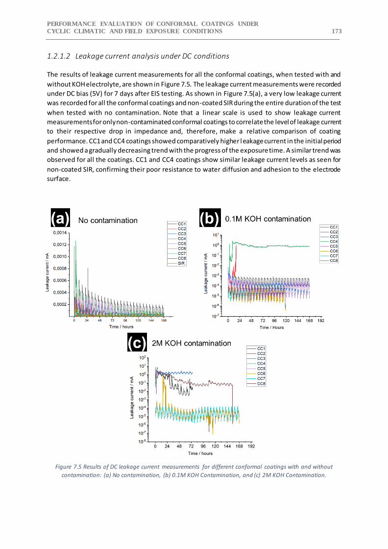
PERFORMANCE EVALUATION OF CONFORMAL COATINGS UNDER
CYCLIC CLIMATIC AND FIELD EXPOSURE CONDITIONS 173
1.2.1.2 Leakage current analysis under DC conditions
The results of leakage current measurements for all the conformal coatings, when tested with and
without KOH electrolyte, are shown in Figure 7.5. The leakage current measurements were recorded
under DC bias (5V) for 7 days after EIS testing. As shown in Figure 7.5(a), a very low leakage current
was recorded for all the conformal coatings and non-coated SIR during the entire duration of the test
when tested with no contamination. Note that a linear scale is used to show leakage current
measurements for only non-contaminated conformal coatings to correlate the level of leakage current
to their respective drop in impedance and, therefore, make a relative comparison of coating
performance. CC1 and CC4 coatings showed comparatively higher leakage current in the initial period
and showed a gradually decreasing trend with the progress of the exposure time. A similar trend was
observed for all the coatings. CC1 and CC4 coatings show similar leakage current levels as seen for
non-coated SIR, confirming their poor resistance to water diffusion and adhesion to the electrode
surface.
Figure 7.5 Results of DC leakage current measurements for different conformal coatings with and without
contamination: (a) No contamination, (b) 0.1M KOH Contamination, and (c) 2M KOH Contamination.
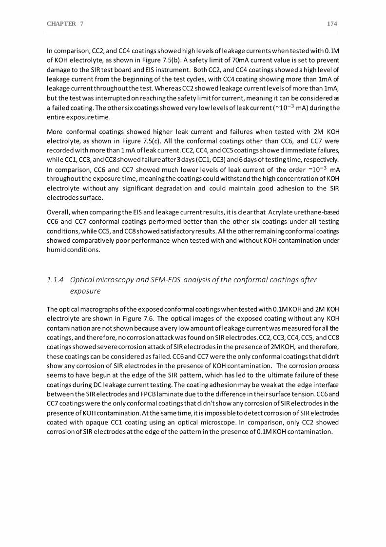
CHAPTER 7 174
In comparison, CC2, and CC4 coatings showed high levels of leakage currents when tested with 0.1M
of KOH electrolyte, as shown in Figure 7.5(b). A safety limit of 70mA current value is set to prevent
damage to the SIR test board and EIS instrument. Both CC2, and CC4 coatings showed a high level of
leakage current from the beginning of the test cycles, with CC4 coating showing more than 1mA of
leakage current throughout the test. Whereas CC2 showed leakage current levels of more than 1mA,
but the test was interrupted on reaching the safety limit for current, meaning it can be considered as
a failed coating. The other six coatings showed very low levels of leak current ( ~10−3 mA) during the
entire exposure time.
More conformal coatings showed higher leak current and failures when tested with 2M KOH
electrolyte, as shown in Figure 7.5(c). All the conformal coatings other than CC6, and CC7 were
recorded with more than 1 mA of leak current. CC2, CC4, and CC5 coatings showe d immediate failures,
while CC1, CC3, and CC8 showed failure after 3 days (CC1, CC3) and 6 days of testing time, respectively.
In comparison, CC6 and CC7 showed much lower levels of leak current of the order ~10−3 mA throughout the exposure time, meaning the coatings could withstand the high concentration of KOH
electrolyte without any significant degradation and could maintain good adhesion to the SIR
electrodes surface.
Overall, when comparing the EIS and leakage current results, it is clear that Acrylate urethane-based
CC6 and CC7 conformal coatings performed better than the other six coatings under all testing
conditions, while CC5, and CC8 showed satisfactory results. All the other remaining conformal coatings
showed comparatively poor performance when tested with and without KOH contamination under
humid conditions.
1.1.4 Optical microscopy and SEM-EDS analysis of the conformal coatings after
exposure
The optical macrographs of the exposed conformal coatings when tested with 0.1M KOH and 2M KOH
electrolyte are shown in Figure 7.6. The optical images of the exposed coating without any KOH
contamination are not shown because a very low amount of leakage current was measured for all the
coatings, and therefore, no corrosion attack was found on SIR electrodes. CC2, CC3, CC4, CC5, and CC8
coatings showed severe corrosion attack of SIR electrodes in the presence of 2M KOH, and therefore,
these coatings can be considered as failed. CC6 and CC7 were the only conformal coatings that didn’t
show any corrosion of SIR electrodes in the presence of KOH contamination. The corrosion process
seems to have begun at the edge of the SIR pattern, which has led to the ultimate failure of these
coatings during DC leakage current testing. The coating adhesion may be weak at the edge interface
between the SIR electrodes and FPCB laminate due to the difference in their surface tension. CC6 and
CC7 coatings were the only conformal coatings that didn’t show any corrosion of SIR electrodes in the
presence of KOH contamination. At the same time, it is impossible to detect corrosion of SIR electrodes
coated with opaque CC1 coating using an optical microscope. In comparison, only CC2 showed
corrosion of SIR electrodes at the edge of the pattern in the presence of 0.1M KOH contamination.
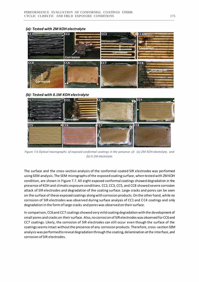
PERFORMANCE EVALUATION OF CONFORMAL COATINGS UNDER
CYCLIC CLIMATIC AND FIELD EXPOSURE CONDITIONS 175
(a): Tested with 2M KOH electrolyte
(b): Tested with 0.1M KOH electrolyte
Figure 7.6 Optical macrographs of exposed conformal coatings in the presence of: (a) 2M KOH electrolyte, and
(b) 0.1M electrolyte.
The surface and the cross-section analysis of the conformal-coated SIR electrodes was performed
using SEM analysis. The SEM micrographs of the exposed coating surface, when tested with 2M KOH
condition, are shown in Figure 7.7. All eight exposed conformal coatings showed degradation in the
presence of KOH and climatic exposure conditions. CC2, CC3, CC5, and CC8 showed severe corrosion
attack of SIR electrodes and degradation of the coating surface. Large cracks and pores can be seen
on the surface of these exposed coatings along with corrosion products. On the other hand, while no
corrosion of SIR electrodes was observed during surface analysis of CC1 and CC4 coatings and only
degradation in the form of large cracks and pores was observed on their surface.
In comparison, CC6 and CC7 coatings showed very mild coating degradation with the development of
small pores and cracks on their surface. Also, no corrosion of SIR electrodes was observed for CC6 and
CC7 coatings. Likely, the corrosion of SIR electrodes can still occur even though the surface of the
coatings seems intact without the presence of any corrosion products. Therefore, cross -section SEM
analysis was performed to reveal degradation through the coating, delamination at the interface, and
corrosion of SIR electrodes.
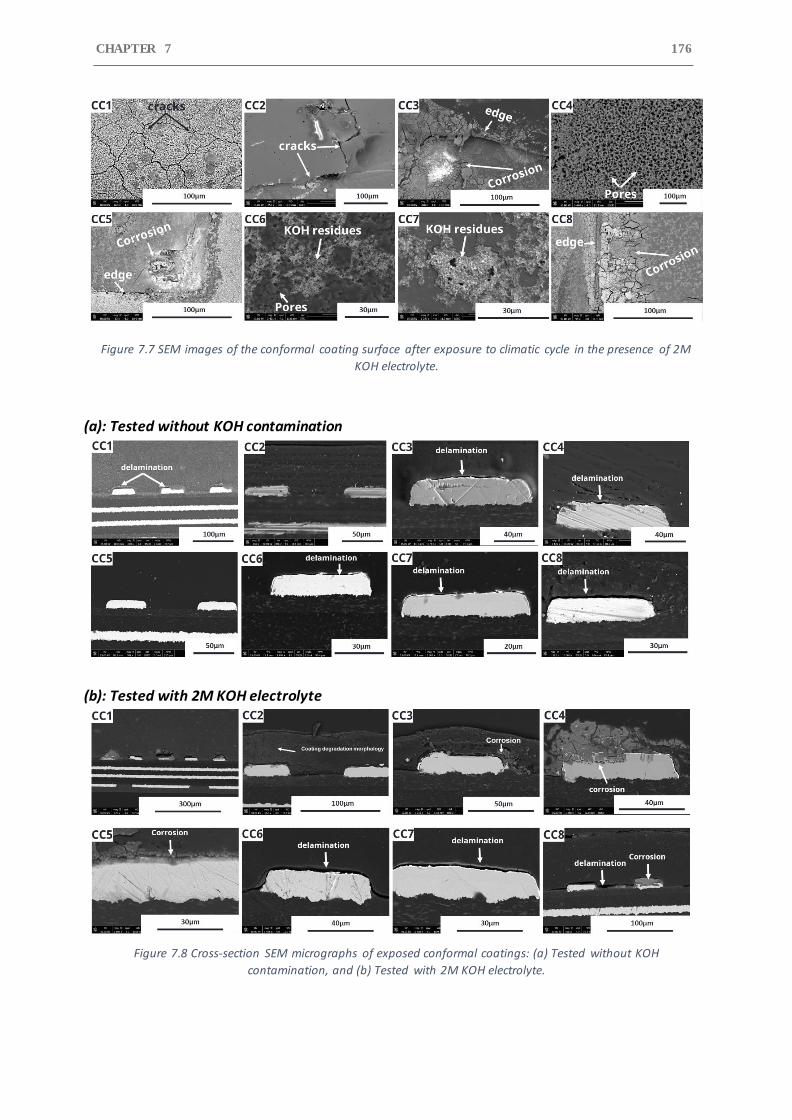
CHAPTER 7 176
Figure 7.7 SEM images of the conformal coating surface after exposure to climatic cycle in the presence of 2M
KOH electrolyte.
(a): Tested without KOH contamination
(b): Tested with 2M KOH electrolyte
Figure 7.8 Cross-section SEM micrographs of exposed conformal coatings: (a) Tested without KOH
contamination, and (b) Tested with 2M KOH electrolyte.
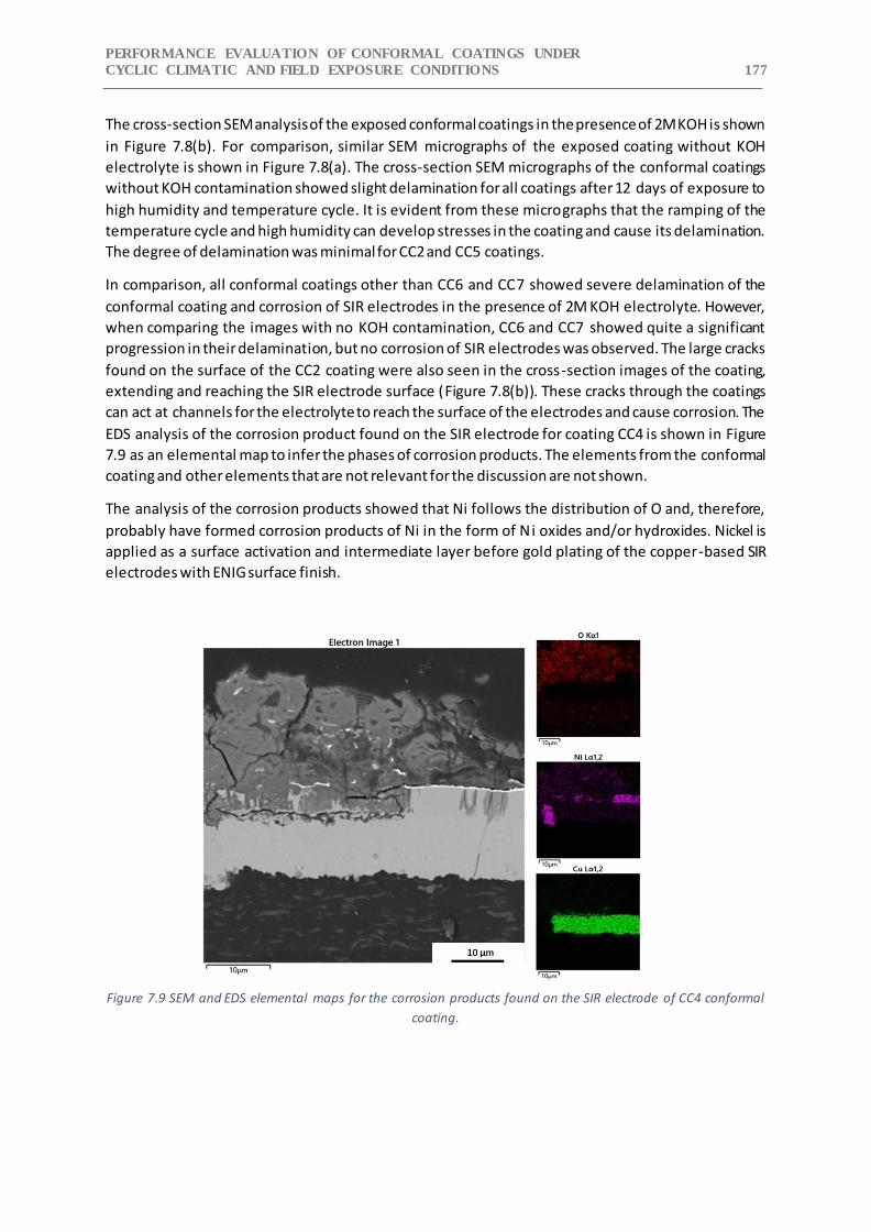
PERFORMANCE EVALUATION OF CONFORMAL COATINGS UNDER
CYCLIC CLIMATIC AND FIELD EXPOSURE CONDITIONS 177
The cross-section SEM analysis of the exposed conformal coatings in the presence of 2M KOH is shown
in Figure 7.8(b). For comparison, similar SEM micrographs of the exposed coating without KOH
electrolyte is shown in Figure 7.8(a). The cross-section SEM micrographs of the conformal coatings
without KOH contamination showed slight delamination for all coatings after 12 days of exposure to
high humidity and temperature cycle. It is evident from these micrographs that the ramping of the
temperature cycle and high humidity can develop stresses in the coating and cause its delamination.
The degree of delamination was minimal for CC2 and CC5 coatings.
In comparison, all conformal coatings other than CC6 and CC7 showed severe delamination of the
conformal coating and corrosion of SIR electrodes in the presence of 2M KOH electrolyte. However,
when comparing the images with no KOH contamination, CC6 and CC7 showed quite a significant
progression in their delamination, but no corrosion of SIR electrodes was observed. The large cracks
found on the surface of the CC2 coating were also seen in the cross-section images of the coating,
extending and reaching the SIR electrode surface (Figure 7.8(b)). These cracks through the coatings
can act at channels for the electrolyte to reach the surface of the electrodes and cause corrosion. The
EDS analysis of the corrosion product found on the SIR electrode for coating CC4 is shown in Figure
7.9 as an elemental map to infer the phases of corrosion products. The elements from the conformal
coating and other elements that are not relevant for the discussion are not shown.
The analysis of the corrosion products showed that Ni follows the distribution of O and, therefore,
probably have formed corrosion products of Ni in the form of Ni oxides and/or hydroxides. Nickel is
applied as a surface activation and intermediate layer before gold plating of the copper-based SIR
electrodes with ENIG surface finish.
Figure 7.9 SEM and EDS elemental maps for the corrosion products found on the SIR electrode of CC4 conformal
coating.
CHAPTER 7 178
The cross-sectional SEM-EDS analysis of the coating revealed that some degree of delamination
occurred mostly for all conformal coatings on their exposure to high humidity and cycling temperature
conditions with no contamination. The delamination was found to be significantly increased when
these conformal coatings were tested with 2M KOH contamination and caused corrosion of the SIR
electrodes. Among all coatings, acrylate urethane based CC6 and CC7 coatings were the only ones that
showed no corrosion of SIR electrodes and less delamination at the interface. These results are
consistent to our observation from EIS and DC leakage current testing.
1.3 Discussion
The primary objective of a conformal coating is to mitigate corrosion attacks by creating a barrier to
insulate and protect the substrate from the external environment such as harmful corrosion
ingredients like ionic contamination and moisture. The rate of diffusion of these corrosion species
through the coating is governed by the thickness of the coating, porosity, and moisture transport
properties (diffusivity and permeability) of applied coatings on the substrate. Moisture saturation
level (solubility) of the coating is also important. The other important factor is the degree of coating
adhesion with the substrate, which is indeed a measure of its bond strength to the substrate surface.
The bond strength is the result of physicochemical interaction between the coating and the substrate,
with ionic and covalent bonds having higher bond strength, while Van der Waals interaction between
polar functional group of coatings with the active substrate produces weak bond strength. Conformal
coatings are meant to resist heat, humidity, oxygen, salts, chemical contact, and micro-movement
stresses to protect electronic components from corrosion.
In the present study, effect of moisture and KOH contamination on the performance of different types
of conformal coatings were evaluated. Moisture is considered one of the most important
deterioration factors for conformal coatings due to the role of water molecules in the interface
degradation mechanisms. Previous studies have shown the effect of moisture content on the
degradation rate of coatings by mechanisms like coating swelling, hydrolytic degradation,
plasticization, and large changes in stoichiometry, which can can directly influence the adhesion of
coatings, interfacial cracking and ultimately can lead to the corrosion of the metallic substrate [10–
13]. These coating failure mechanisms will depend on the time interval of wet and dry exposure cycle,
which will determine the rate of water transportation, the moisture content in coatings, plus the
occurrence of hydrolysis and reactions that involve water. The presence of KOH contamination on the
surface of conformal coatings will accelerate the rate of degradation by causing damage to the
chemical structure of the polymers and therefore cause easy water diffusion. Once the moisture
reaches the coating-PCBA interface, KOH also provides good electrolyte properties and assists coating
delamination. Conformal coatings CC1, CC2, CC3, CC4 and CC5 showed a significant drop in their
impedance when tested with KOH contamination, with most of them showing an immediate drop in
impedance within the few hours of their exposure time and CC5 showing the same magnitude of
impedance drop after 48 hours of exposure to climatic cycle. Such a significant decrease in the
impedance values for these coatings is related to the coating adhesion loss at the interface and an
increase rate of electrochemical reaction on the SIR electrode surface due to the presence of KOH
electrolyte. The fluctuations observed in impedance values when tested with 2M KOH electrolyte are
due to the higher electrochemical reaction rate taking place on the SIR electrode surface, producing
unstable EIS circuit conditions.
PERFORMANCE EVALUATION OF CONFORMAL COATINGS UNDER
CYCLIC CLIMATIC AND FIELD EXPOSURE CONDITIONS 179
Acrylic urethane coatings are highly recommended as a corrosion protection method for automotive
electronics and consumer electronics due to their high weathering resistance, good physical
properties and excellent substrate/coating adhesion [14]. Among all the tested conformal coatings,
acrylic urethane-based CC6 and CC7 showed better performance during exposure to harsh climatic
cycle for both with and without KOH contamination. The acrylic urethane coatings generally consist
of acrylic binders, two-pack polyurethane, and thermoplastic acrylic polymers [14]. It is considered
that urethane copolymer are composed of a soft segment and a hard segment. The soft segment
consists of a mixture of various polyols and ammonia, while the hard segment includes chain
extenders and commonly uses isocyanate as a curing agent [15,16]. The isocyanates are classified as
aromatic or aliphatic. Of these types, aliphatic-based isocyanate curing agents usually react with water
from the moisture to form a different ratio of NCO/OH, which produces dense cross linking through
the formation of urea bonds [17,18]. Coating with a high ratio of NCO/OH has more urethane groups
and has been reported to have shown better adhesion and corrosion protection under humid
exposure [19]. Whereas, Acrylate polymer coatings without any urethane copolymer have been
reported to show poor adhesion and cohesive strength upon exposure to moisture and high-
temperature conditions [20,21]. The acrylate-based CC3 conformal coating showed severe
delamination and corrosion when tested with 2M KOH. The delamination of the coating was observed
in the absence of KOH contamination as well, which can only be influenced by the exposure condition
of high humidity and ramping temperature.
Between the two-epoxy coatings, CC5 coating showed promising performance when tested under
both with and without low KOH electrolyte (0,1M) contamination but showed failure in the presence
of a high KOH concentration of 2M. Epoxy coatings are low molecular resins, generally crosslinked
with amines or polyamides to form high molecular weight material. They are known to have a high
affinity towards moisture absorption due to the presence of hydroxyl groups created by the epoxide
ring-opening reaction with primary and secondary amines [22]. Moisture absorption can create
microcracks in epoxy coatings in which water and other contaminations gets collected. Furthermore,
Internal stresses resulting from the ramping of temperature cycles during exposure can contribute to
adhesive or cohesive failure of these coating. All this will ultimately lead to the adhesion loss between
epoxy coatings and substrate[23].
Fluoropolymer coatings are known to exhibit high hydrophobicity, which makes them a desirable
coating choice for the protection of electronics from humidity-related failures. Their hydrophobic
nature is due to the presence of high strength C-F bond created by forming long fluoroalkyl groups
(carbon fluorination). However, in the presence of KOH contamination, fluoropolymer-based CC2
coating showed severe coating degradation, delamination, corrosion of SIR electrodes, and early
failure during DC testing (Figure 7.7, and Figure 7.8). Certain fluoropolymers have been shown to have
high degradation in alkaline environments [24].
The elastic adhesive type CC1 coating showed low impedance for all the test conditions and failure
when tested with 2M KOH under DC-bias conditions. The degradation of the elastic adhesive type
coatings can occur by absorption of water molecules into the polymer matrix, which can cause coating
hydrolysis and lowers its glass transient temperature by reducing the bond strength between
molecules. This can cause swelling and plasticization of the polymer matrix. The failure initially starts
as a cohesive failure with degradation of the chemical structure of the coating and ultimately proceeds
into adhesive failure at the coating/substrate interface. The presence of KOH can accele rate the
degradation and breaking of structural bonds of the coating, thus rendering them with poor
performance.
CHAPTER 7 180
1.4 Conclusion
The performance of different types of conformal coating were evaluated by performing EIS and DC
testing using a Test FPCB board under humid conditions with and without the presence of KOH
contamination. The test board was designed to represent an actual HA electronic circuit, thereby
making it possible to study the impact of design parameters, manufacturing residues and exposure
condition on the corrosion failure of HA components and testing of conformal coatings.
The results from the conformal coating testing clearly demonstrated that acrylate urethane coatings
CC6 and CC7 showed high impedance and lower leak current values compared to other conformal
coatings under all testing conditions. Moreover, no significant coating degradation and corrosion of
SIR electrodes were observed during the SEM analysis, even when acrylate urethane coatings were
tested with 2M KOH electrolyte contamination. The excellent performance of the acrylate urethane
coating is because of the presence of curing agent isocyanate, which can react with moisture to form
dense crosslink by forming urea bonds and thereby limiting the moisture diffusion rate through the
coating. Epoxy-based CC4 coating showed the worst performance in all exposure conditions compared
to other conformal coatings.
PERFORMANCE EVALUATION OF CONFORMAL COATINGS UNDER
CYCLIC CLIMATIC AND FIELD EXPOSURE CONDITIONS 181
References
[1] J.J. Licari, Coating Materials for Electronic Applications: Polymers, Processing, Reliability, Testing, 2003.
[2] U. Rathinavelu, M.S. Jellesen, P. Moller, R. Ambat, Effect of no-clean flux residues on the performance of acrylic conformal coating in aggressive environments, IEEE Trans. Components, Packag. Manuf. Technol. 2 (2012). https://doi.org/10.1109/TCPMT.2012.2186456.
[3] U. Rathinavelu, M.S. Jellesen, R. Ambat, Effect of solder flux residue on the performance of silicone conformal coatings on printed circuit board assemblies, Corros. Eng. Sci. Technol. (2013). https://doi.org/10.1179/1743278213Y.0000000096.
[4] A. Khangholi, F. Li, K. Piotrowska, S. Loulidi, R. Ambat, G. Van Assche, A. Hubin, I. De Graeve, Humidity Robustness of Plasma-Coated PCBs, J. Electron. Mater. 49 (2020). https://doi.org/10.1007/s11664-019-07714-5.
[5] O.Ø. Knudsen, A. Forsgren, Corrosion control through organic coatings, second edition, 2017. https://doi.org/10.1201/9781315153186.
[6] A. Amirudin, D. Thieny, Application of electrochemical impedance spectroscopy to study the degradation of polymer-coated metals, Prog. Org. Coatings. 26 (1995). https://doi.org/10.1016/0300-9440(95)00581-1.
[7] S. Zhan, M.H. Azarian, M.G. Pecht, Surface insulation resistance of conformally coated printed circuit boards processed with no-clean flux, IEEE Trans. Electron. Packag. Manuf. 29 (2006). https://doi.org/10.1109/TEPM.2006.882496.
[8] S.I.R.T. Group, IPC-9201: Surface Insulation Resistance Handbook, IPC, Institute for Interconnecting and Packaging Electric Circuits, Northbrook, IL, USA, 1996.
[9] IPC, IPC-TM-650-2.3.25D Detection and Measurement of Ionizable Surface Contaminants by Resistivity of Solvent Extract (ROSE), IPC Test Methods Man. (2012) 1–5.
[10] T. Nguyen, J. Martin, E. Byrd, Relating laboratory and outdoor exposure of coatings: IV. Mode and mechanism for hydrolytic degradation of acrylic-melamine coatings exposed to water vapor in the absence of UV light, J. Coatings Technol. 75 (2003). https://doi.org/10.1007/bf02720521.
[11] S. Hollande, J.L. Laurent, Degradation process of an industrial thermoplastic elastomer polyurethane-coated fabric in artificial weathering conditions, J. Appl. Polym. Sci. 73 (1999). https://doi.org/10.1002/(SICI)1097-4628(19990919)73:12<2525::AID-APP21>3.0.CO;2-D.
[12] L.P. Real, J.L. Gardette, A. Pereira Rocha, Artificial simulated and natural weathering of poly(vinyl chloride) for outdoor applications: The influence of water in the changes of properties, Polym. Degrad. Stab. 88 (2005). https://doi.org/10.1016/j.polymdegradstab.2004.11.012.
[13] D.Y. Perera, Effect of pigmentation on organic coating characteristics, Prog. Org. Coatings. 50 (2004). https://doi.org/10.1016/j.porgcoat.2004.03.002.
[14] T.V. Nguyen, X.H. Le, P.H. Dao, C. Decker, P. Nguyen-Tri, Stability of acrylic polyurethane coatings under accelerated aging tests and natural outdoor exposure: The critical role of the used photo-stabilizers, Prog. Org. Coatings. 124 (2018). https://doi.org/10.1016/j.porgcoat.2018.08.013.
CHAPTER 7 182
[15] M.M. Adnan, A.R.M. Dalod, M.H. Balci, J. Glaum, M.A. Einarsrud, In situ synthesis of hybrid inorganic-polymer nanocomposites, Polymers (Basel). 10 (2018). https://doi.org/10.3390/polym10101129.
[16] V. V. Gite, P.P. Mahulikar, D.G. Hundiwale, Preparation and properties of polyurethane coatings based on acrylic polyols and trimer of isophorone diisocyanate, Prog. Org. Coatings. 68 (2010). https://doi.org/10.1016/j.porgcoat.2010.03.008.
[17] F. Lu, B. Song, P. He, Z. Wang, J. Wang, Electrochemical impedance spectroscopy (EIS) study on the degradation of acrylic polyurethane coatings, RSC Adv. 7 (2017). https://doi.org/10.1039/c6ra26341k.
[18] A.S. Khanna, High-Performance Organic Coatings, 2008. https://doi.org/10.1533/9781845694739.
[19] D.K. Chattopadhyay, K.V.S.N. Raju, Structural engineering of polyurethane coatings for high performance applications, Prog. Polym. Sci. 32 (2007). https://doi.org/10.1016/j.progpolymsci.2006.05.003.
[20] K.T. Tan, C.C. White, D.L. Hunston, C. Clerici, K.L. Steffens, J. Goldman, B.D. Vogt, Fundamentals of adhesion failure for a model adhesive (PMMA/Glass) joint in humid environments, J. Adhes. 84 (2008). https://doi.org/10.1080/00218460802004428.
[21] J.M. Yeh, C.J. Weng, W.J. Liao, Y.W. Mau, Anticorrosively enhanced PMMA-SiO2 hybrid coatings prepared from the sol-gel approach with MSMA as the coupling agent, Surf. Coatings Technol. 201 (2006). https://doi.org/10.1016/j.surfcoat.2006.03.011.
[22] D. Colombini, J.J. Martinez-Vega, G. Merle, Dynamic mechanical investigations of the effects of water sorption and physical ageing on an epoxy resin system, Polymer (Guildf). 43 (2002). https://doi.org/10.1016/S0032-3861(02)00272-0.
[23] M. Zubielewicz, A. Królikowska, The influence of ageing of epoxy coatings on adhesion of polyurethane topcoats and protective properties of coating systems, Prog. Org. Coatings. 66 (2009). https://doi.org/10.1016/j.porgcoat.2009.06.014.
[24] D. Cheneler, J. Bowen, S.D. Evans, M. Górzny, M.J. Adams, M.C.L. Ward, Characteristics and durability of fluoropolymer thin films, Polym. Degrad. Stab. (2011). https://doi.org/10.1016/j.polymdegradstab.2010.12.022.
CHAPTER 8: OVERALL DISCUSSION 183
8 Overall Discussion
Aim of this chapter is to provide an overall discussion and perspective from the work combining all
the results presented in various chapters. The results shown in various chapters show that the climatic
reliability of hearing aid devices and its components were significantly affected by the synergetic effect
of environmental conditions (humidity temperature) and contamination.
As shown, the PoF based failure analysis of hearing aids and its statistical failure analysis from different
markets was the key initial step in finding the corrosion failure mechanisms, its causes, failure
percentage and probability of different components. Among all the markets, high failure percentage
of hearing aid components was observed from tropical regions. The prominent failure cause was due
to the presence of aggressive high pH KOH electrolyte because of Zn-air battery leakage, which caused
degradation of conformal coatings, corrosion of the hearing aid circuitry components, hand solder
joints, microphones, battery contacts and many other components. Other contamination such as
human sweat and atmospheric aerosols were found on the corroded areas of different hearing aid
components as well. The majority of corrosion morphology found on the failed components was mud-
crack type, which was consistent in all the analyzed markets and is an indication of wet corrosion
process that could have taken place in the presence of moisture and human sweat present inside the
device during field operation. The effect of summer season on the failure of hearing aid components
was presented for tropical markets, which clearly showed a significant increase in the failure rate of
different components with the onset of summer season in these regions. This observation was
correlated to the increase rate of battery leakage and human perspiration due to harsh temperature
and humidity conditions during summer months, which will increase the amount of corrosive ionic
species build up inside the device, thereby accelerating the corrosion failure rates of components.
Various corrosion failure modes and mechanisms were elucidated during the root cause failure
analysis, of which the most prominent were the galvanic corrosion, localized corrosion attack and
leakage current generated due to the bridging of opposite terminals by conductive and hygroscopic
corrosion products. The latter failure mechanism is responsible for the intermittent failures, which
with the buildup of corrosion products will eventually lead to permanent failure of the device. Among
all the components, microphones showed the higher failure percentage across all the markets. The
reason being the increase in the rate of 𝐶𝑙− and 𝑂𝐻− ions mobility towards microphone due to high
electric field generated by the pre-charged membrane plate and electronic circuit of the microphone.
The knowledge from these studies was very important in demonstrating the type of contamination
causing corrosion failure and the synergetic effect of material choice, product geometries and design
error that resulted in the failure of components. Furthermore, it can aid in the development of
accelerated corrosion test methods for quality qualification of products and components by defining
test stresses and other parameters responsible for device failure in the field.
Up until now, no studies have ever mentioned or investigated the criticality of leaking ZABs towards
corrosion failure of hearing aids. Since it is the major failure cause of hearing aid devices in the field,
the study was conducted to investigate the effect of temperature condition and exposure duration on
the leakage of ZAB from three different types of widely used hearing aid batteries. Note that the
batteries were tested under high humidity and the effect of varying temperature level and exposure
duration were evaluated based on the amount of the electrolyte leakage. The hygroscopic nature of
the KOH residues and its impact on the corrosion reliability of electronics were evaluated as well. The
results showed that all the battery variant relatively showed similar tendency of battery leakage when
exposed to saturated humidity and high temperature conditions for longer exposure time of 10 days.
CHAPTER 8: OVERALL DISCUSSION 184
Between the two effects, the temperature had more significant impact on the amount of KOH released
from the battery during the test compared to the exposure duration. The SEM-EDS analysis of the
batteries after the test showed damage of the sealant gasket and clogging of ventilation holes from
the leakage of KOH residues. The EDS analysis confirmed the chemical nature of the residues and Zn
was found in the leakage product. The corrosion of Zn electrode inside ZAB can take place due to
water ingress from exposure condition, which will lead to the formation Zn corrosion products and
hydrogen gas. The generation of hydrogen gas can cause build of pressure inside the cell, which can
lead to outgassing and leakage of KOH electrolyte along with corrosion products of Zn.
The corrosion reliability of any electronic device depends on the thickness of water layer formation
on the surface of the electronic components such as PCBA, which is heavily influenced by the presence
of type and amount of contamination on the PCBA surface. The resul ts from the sorption/desorption
test of KOH crystals revealed that the crystals starts absorbing water molecules at very low RH (10%
RH) and showed complete dilution and deliquescence at ~ 50 % RH. The results suggests that KOH
residues are highly hygroscopic in nature and their presence inside the HA device will lower its critical
RH, thus making them more prone to early failure in the field. Their effect on the failure of electronics
was evaluated with EIS testing using interdigitated test board, which showed sudden drop in the SIR
impedance at ~ 40% RH and remained low up until the 99% RH. On decreasing the humidity back to
10% RH, recovery of the impedance back to its original values didn’t take palce suggesting that KOH
residues are still withholding water molecules and doesn’t allow efflorescence of the crystals
(crystallization). The results from these studies on Zinc air battery revealed the fact that tropical
regions where high temperature and humidity conditions are adverse, hence most vulnerable market
for the corrosion failure of hearing aids due to battery leakage.
The information from the root cause failure analysis of the hearing aids from different markets was
used in the development of accelerated corrosion test methods to estimate the reliab ility of devices
in relatively short period of time. The key factor responsible in the development of the accelerated
corrosion method require thorough knowledge of the corrosion inducing stresses such as climatic
condition and contamination. Such information were deduced from the field failure analysis study of
hearing aids and it led to the development of two different types of accelerated corrosion test
methods i.e. KOH induced corrosion test method and sweat induced corrosion test method. The
results from the KOH induced corrosion test method of hearing aid device were able to produce and
mimic field failures accurately and showed high failure percentage of microphones as seen similarly
in the market as well. Failure of other components and degradation of conformal coating as observed
in the field were successfully replicated in this laboratory scale corrosion test method.
The sweat induced corrosion test methods were of two types based on the way the sweat is applied
on the device i.e. sweat spray test and sweat box test. Both the test methods were insufficient in
replicating the sweat induced corrosion failure mechanisms from the field. Only microphones failure
was observed, with no sign of corrosion on any other components during the test. This was due to the
fact that low amount of sweat ions were able to enter the device, which preferentially travelled
towards microphones and thus not causing corrosion of their components. Another important reason
was that the test was not able to cause degradation and delamination of conformal coating, which
was observed as one of the major failure mechanism for the corrosion of hand solder joints and
electronic circuitry. Therefore, an optimized version of sweat induced corrosion method was
proposed, inspired from the salt spray test method. The proposed test chamber is capable of
automated periodic depositing of salt crystals on the device during the climatic exposure test and the
hearing device are mounted on the peltier stage to control the thickness of the conden sed layer
forming on its surface. In this way the corrosion factors such as thicknes of water layer formation and
CHAPTER 8 185
the amount of salt residues deposited on the device can be controlled in a much better way. The test
optimization also consist of some pre-tests such as vibration and device drop test with an attempt to
introduce mechanical damage to the conformal coatings.
The hearing aids electronic circuitry is protected from humidity and external ionic contamination by
several different types of conformal coatings. The SMT components are protected by Silicone based
coatings, while the hand solderings are protected by using Fluoropolymer conformal coatings.
However, both types of conformal coatings developed failure in the form of delamination and cracks
during field operation, which was consistent in all the tested devices across all the markets. There are
several factors that can cause failure of conformal coatings apart from the degradation due to
aggressive ions such as KOH and salt residues. These factors are the flux residues present on the HA
circuitry, movement of the bending zone and vibrations (device fall and other shock impact). Since it
is difficult to test the effects of these factors on the failure of conformal coatings inside the device, a
Test FPCB was designed and developed, which represents the actual hearing aid circuitry, and are
manufactured using the similar processing methods. Therefore, all the parameters affecting the
performance of conformal coating can be investigated using this Test FPCB.
The test FPCB was used in the testing of the existing and performance evaluation of potential
candidates of conformal coatings using interdigitated pattern of the test board. The EIS and DC leakage
current test showed that acrylate polyurethane coatings have superior performance (high impedance
and very low leakage current) compared to the other coatings when tested with and without KOH
contamination under cyclic humidity exposure. Whereas, other coatings showed severe delamination
and high leakage current in the presence of KOH, which was more severe with the increase in the
concentration of KOH contamination. An important observation was made during EIS testing, which
stated that all conformal coatings takes up moisture within the few hours of their exposure to test
conditions and thus their performance is mostly dependent on the adhesion of the coating with the
substrate. This was the reason that even though epoxies are hard and dense, they didn’t had good
adhesion bonding with the substrate which resulted in their poor performance during the exposure
to high humidity, temperature cycle and KOH contamination.
CHAPTER 9: OVERALL CONCLUS IONS 186
9 Overall Conclusions
1. Field failed hearing aid devices from tropical regions showed overall higher failure percentage
of components as compared to other markets such as European, USA and Japan. Among
various failed components, microphones were reported with highest failure percentage
across all the markets. Among other components, battery contacts, hand solderings, LED and
FPCB were most severely attacked by corrosion and this observation was consistent among
all the markets.
2. Various type of corrosion failure mechanisms were found on different hearing aid
components, of which the most prominent were galvanic corrosion and localized corrosion
attack. Such severe corrosion process produced voluminous corrosion products, which were
found spread all over the FPCB surface and bridged opposite terminals to cause leakage
current failures. Other failure such as ECM was observed between microswitch terminals, on
microphone circuit and TF circuit components.
3. The overall failure mechanism for the corrosion of most hearing aid components was related
to the failure of conformal coating protection. The most prominent failure cause found for
failed devices from tropical region was the KOH electrolyte leakage from ZAB. In other
markets, the failure due to KOH electrolyte was limited to the microphones failure, where
other components showed corrosion failure due to high ingress of human sweat residues
(salt).
4. The failure due to both leakage of battery and human sweat residues were affected by the
climatic season. Summer period in tropical region caused significant rise in the failure rate of
components. The failures were correlated to the high battery leakage and perspiration rate
caused by extreme weather conditions during summer season in tropical regions.
5. The climatic testing of different ZAB variants used in hearing aids showed that the amount of
electrolyte leakage is more temperature affected than exposure duration. B1 battery variant
showed higher succeptibility for electrolyte leakage at higher temperatures compared to
other variants. High temperature and saturated humid conditions can cause water ingress
inside the batteries and subsequent corrosion of zinc electrode. The buildup of hydrogen gas
due to corrosion of electrode can rupture the cell and damage the sealant gasket. SEM-EDS
analysis confirmed zinc corrosion product along with electrolyte residues found at the sealant
and ventilation holes.
6. KOH residues showed that it exhibits high hygroscopic behavior with deliquescence RH of
around 50%. Significant sudden drop in impedance between SIR electrode was observed at
around similar RH, thus confirming its hygroscopic nature, which can easily cause SIR
reduction due to leak current and subsequent ECM failures in electronic PCBA.
7. KOH induced and sweat induced corrosion test methods were developed to evaluate the
climatic reliability of hearing aid devices. The knowledge about the concentration and type of
corrosion contamination found during the field failure analysis were implemented as
corrosion accelerating factors. The efficiency of the test method was evaluated by comparing
the failures from the field. KOH induced test method was capable of producing failures, which
CHAPTER 9: OVERALL CONCLUS IONS 187
were representative of field failure. However, sweat induced corrosion test method were
found to cause no failure of hearing aid components other than microphones failures.
Optimization to the sweat induced test method were proposed as an attempt to reproduce
sweat induced failure similar to field failures.
8. The performance evaluation of conformal coatings was done by using a specially designed
hearing aid Test FPCB board. EIS, DC leak current testing and post SEM-EDS analysis of the
coatings were employed methods for comparing performances of different coating
candidates. Among all the tested conformal coatings, polyurethane based conformal coating
CC6 and CC7 showed better performance under exposure to cyclic humidity and KOH
contamination. Among other coating types, epoxy based CC5 and urethane based CC8 showed
promising results (high impedance and low leakage current) for low concentration of KOH
contamination.
9.1 Recommendations for improving the humidity robustness of
hearing aid devices
1 High corrosion failure percentage of microphones component was due to the fact that its
electronic circuit is not protected from external corrosive ions. Therefore, application of suitable
conformal coating is necessary to protect electronic circuit of microphones from corrosion
failures.
2 Severe delamination of conformal coating occurred on the hand solderings, which subsequently
led to the localized attack of the solder terminals. The internal factor that can lead to the
delamination of conformal coating is the presence of high solder flux residues around the hand
solder, which can interfere with the adhesion of the coating. This issue can be avoided or
minimized if a suitable post cleaning process is adopted by the hearing aid manufacturer to
remove any process related contamination from its circuitry components.
3 Battery contacts showed severe galvanic corrosion at the contact zone and delamination of Au
layer. The corrosion was due to the high porosity in gold layer and due to its wear because of
sliding motion of battery. The galvanic corrosion can be avoided either by increasing the thickness
of the gold, which might not be an economical solution for the manufacturer or by using different
interlayers below Au that will avoid any galvanic coupling. An example of such an interlayer is
SnNi as replacement for Ni intermediate layer, which have shown much better corrosion
performance as compared to conventional ENIG plating.
4 The capillary gaps created by the W-link coil windings resulted in the entrapment of corrosion
and salt residues, which resulted in the alteration of its dielectric properties and thus affected
their working functionality. The coil windings can be covered with additional lacquer protection
to smoothen and flatten out the surface of the windings.
5 Selective gold plating is used at various places on the FPCBA of hearing aids to increase surface
wettability and solderability of hand soldering terminals. However, it was observed during the
field failure analysis that only the soldering terminals were protected with the conformal
coatings, leaving out the thin gold plating areas. Once the conformal coating develops cracks and
CHAPTER 9 188
surface delamination, the hand solder will be exposed to accelerated corrosion attack due to
galvanic coupling with the thin gold plating. This will lead to buildup of brittle corrosion product
and eventually will cause breakage of the hand soldering joints. The best approach to avoid this
is by averting the galvanic coupling between gold and solder alloy by applying conformal coatings
on both of them. This is operator dependent task (conformal coatings are hand applied at hand
solderings) and due to the miniaturized size of the device, it is difficult to observed with naked
eye if conformal coating is applied at designated places. In that case, strict quality control
measures are required to check devices for such abnormalities.
6 The existing test methods for testing corrosion reliability of hearing aids due to human sweat are
incapable in truly replicating the field conditions. Instead, a better optimized design of a corrosion
test chamber was proposed which include insitu depsotion of sweat aerogols along with pelitier
based device mouting stage that can provide much better simulation of field conditions and
freedom to control corrosion acceleration factors.
7 Development of Test FPCB board which include all the components that are originally mounted
on a hearing aid device provide various possibilities to investigate performance of these
components under field exposure test conditions using scientific electrochemical test methods
(EIS, DC leak test etc). Some of the components that are succeptibile towards moisture and are a
part of Test FPCB board are W-link coil, battery contacts and hand solderings. Therefore, such
device representative Test FPCB boards are very useful in investigation and understanding the
failure mechanisms and derive one-to –one correlations with the corrosion accelerating factors
for each individual hearing aid component.
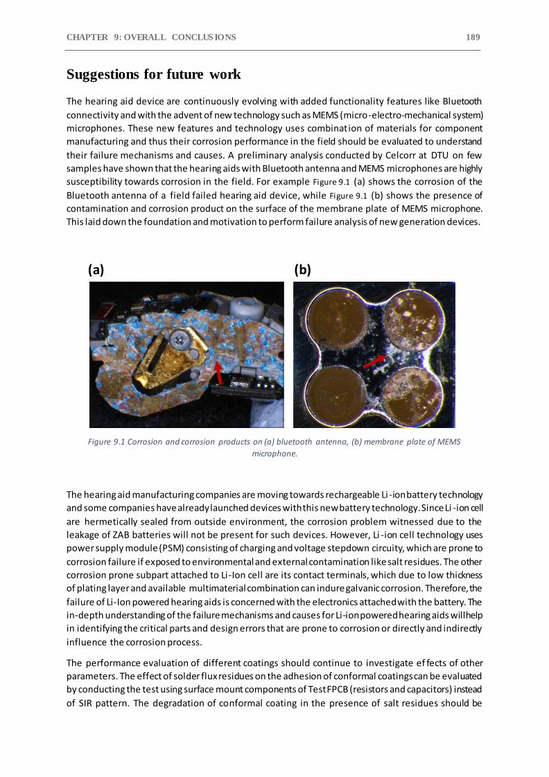
CHAPTER 9: OVERALL CONCLUS IONS 189
Suggestions for future work
The hearing aid device are continuously evolving with added functionality features like Bluetooth
connectivity and with the advent of new technology such as MEMS (micro-electro-mechanical system)
microphones. These new features and technology uses combination of materials for component
manufacturing and thus their corrosion performance in the field should be evaluated to understand
their failure mechanisms and causes. A preliminary analysis conducted by Celcorr at DTU on few
samples have shown that the hearing aids with Bluetooth antenna and MEMS microphones are highly
susceptibility towards corrosion in the field. For example Figure 9.1 (a) shows the corrosion of the
Bluetooth antenna of a field failed hearing aid device, while Figure 9.1 (b) shows the presence of
contamination and corrosion product on the surface of the membrane plate of MEMS microphone.
This laid down the foundation and motivation to perform failure analysis of new generation devices.
Figure 9.1 Corrosion and corrosion products on (a) bluetooth antenna, (b) membrane plate of MEMS
microphone.
The hearing aid manufacturing companies are moving towards rechargeable Li -ion battery technology
and some companies have already launched devices with this new battery technology. Since Li -ion cell
are hermetically sealed from outside environment, the corrosion problem witnessed due to the
leakage of ZAB batteries will not be present for such devices. However, Li -ion cell technology uses
power supply module (PSM) consisting of charging and voltage stepdown circuity, which are prone to
corrosion failure if exposed to environmental and external contamination like salt residues. The other
corrosion prone subpart attached to Li-Ion cell are its contact terminals, which due to low thickness
of plating layer and available multimaterial combination can indure galvanic corrosion. Therefore, the
failure of Li-Ion powered hearing aids is concerned with the electronics attached with the battery. The
in-depth understanding of the failure mechanisms and causes for Li-ion powered hearing aids will help
in identifying the critical parts and design errors that are prone to corrosion or directly and indirectly
influence the corrosion process.
The performance evaluation of different coatings should continue to investigate ef fects of other
parameters. The effect of solder flux residues on the adhesion of conformal coatings can be evaluated
by conducting the test using surface mount components of Test FPCB (resistors and capacitors) instead
of SIR pattern. The degradation of conformal coating in the presence of salt residues should be
(a) (b)
CHAPTER 9 190
conducted as KOH and sweat residues together were the most prominent failure cause for hearing
aids. Furthermore, the effect of bending the FPCB on the adhesion of conformal coating is important
since the conformal coated FPCB are bended several times during the component mounting and
device assembly process. Test FPCB consist of bending areas to study the effect of FPCB bending
towards conformal coating failure.

DTU Mechanical EngineeringSection of Materials and Surface EngineeringTechnical University of Denmark
Produktionstorvet, Bld. 425DK-2800 Kgs. Lyngby DenmarkTlf.: +45 4525 2205Fax: +45 4525 1961
www.mek.dtu.dk
June 2021
ISBN: 978-87-7475-658-3
Related Documents