1. AIM: To Study of lab equipments and components: CRO, Multimeter, Function Generator, Power supply- Active, and Passive Components & Bread Board. 2. APPARATUS REQUIRED: S.No. Apparatus / Software Used Specification Quantity 1. CRO 1 2. Function Generator 1 3. Multimeter 1 4. Resistance & Capacitance 1 5. Power supply & Bread Board 1 3. THEORY: CRO (Cathode Ray Oscilloscope) The oscilloscope is one of the most important electronic instruments available for making circuit measurements. It displays a curve plot of time-varying voltage on the oscilloscope screen. The oscilloscope provided with Multisim Electronics Workbench is a dual trace oscilloscope that looks and acts like a real oscilloscope. A dual trace oscilloscope allows the user to display and compare two time-varying voltages at one time. The controls on the oscilloscope are as follows: 1. The TIME BASE control adjusts the time scale on the horizontal axis in time per division when Y/T is selected. When B/A is selected, the horizontal axis no longer represents time. The horizontal axis now represents the voltage on the channel A input and vertical axis represents the voltage on channel B input. When A/B is selected, the horizontal axis represents the voltage on the channel B input and the vertical axis represents the voltage on the channel A input. The Dev Bhoomi Institute Of Technology Department of Electronics and Communication Engineering LABORATORY MANUAL PRACTICAL INSTRUCTION SHEET EXPERIMENT NO. 1&2 ISSUE NO. : ISSUE DATE: REV. NO. : REV. DATE : PAGE: 5 LABORATORY Name & Code: PCB LAB PEC-452 SEMESTER: IV

Welcome message from author
This document is posted to help you gain knowledge. Please leave a comment to let me know what you think about it! Share it to your friends and learn new things together.
Transcript
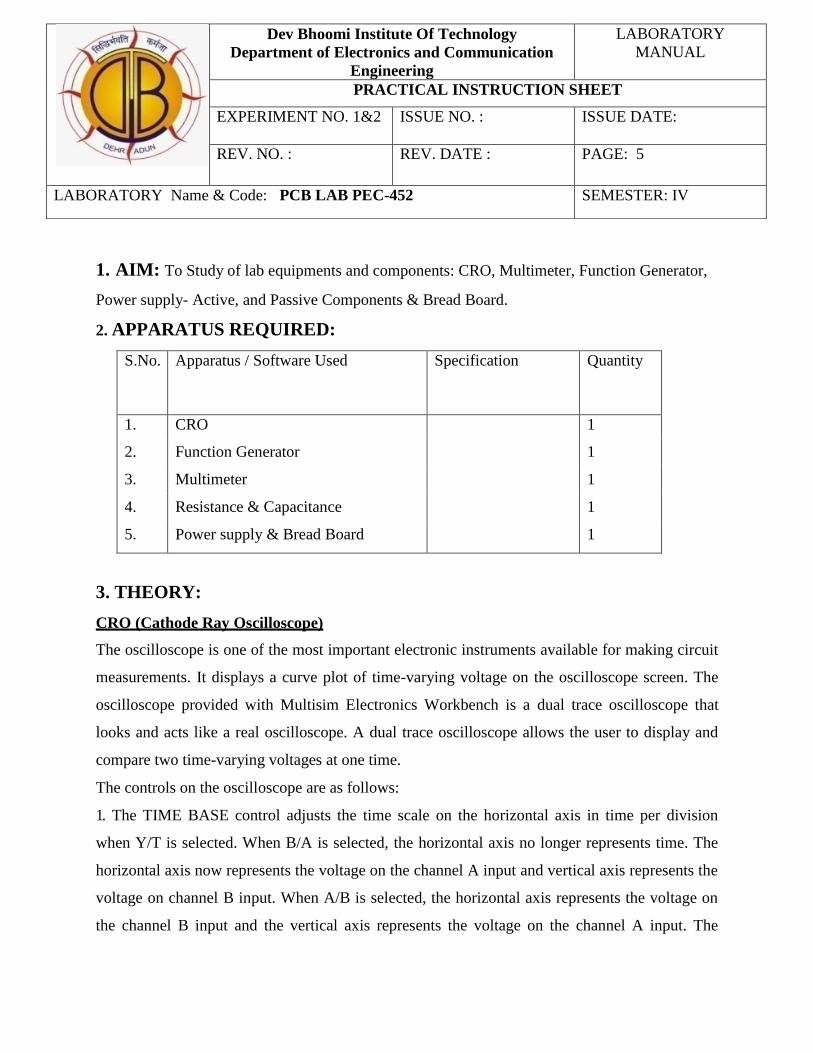
1. AIM: To Study of lab equipments and components: CRO, Multimeter, Function Generator,
Power supply- Active, and Passive Components & Bread Board.
2. APPARATUS REQUIRED:
S.No. Apparatus / Software Used Specification Quantity
1. CRO 1
2. Function Generator 1
3. Multimeter 1
4. Resistance & Capacitance 1
5. Power supply & Bread Board 1
3. THEORY:
CRO (Cathode Ray Oscilloscope)
The oscilloscope is one of the most important electronic instruments available for making circuit
measurements. It displays a curve plot of time-varying voltage on the oscilloscope screen. The
oscilloscope provided with Multisim Electronics Workbench is a dual trace oscilloscope that
looks and acts like a real oscilloscope. A dual trace oscilloscope allows the user to display and
compare two time-varying voltages at one time.
The controls on the oscilloscope are as follows:
1. The TIME BASE control adjusts the time scale on the horizontal axis in time per division
when Y/T is selected. When B/A is selected, the horizontal axis no longer represents time. The
horizontal axis now represents the voltage on the channel A input and vertical axis represents the
voltage on channel B input. When A/B is selected, the horizontal axis represents the voltage on
the channel B input and the vertical axis represents the voltage on the channel A input. The
Dev Bhoomi Institute Of Technology
Department of Electronics and Communication
Engineering
LABORATORY
MANUAL
PRACTICAL INSTRUCTION SHEET
EXPERIMENT NO. 1&2 ISSUE NO. : ISSUE DATE:
REV. NO. : REV. DATE :
PAGE: 5
LABORATORY Name & Code: PCB LAB PEC-452 SEMESTER: IV

X_POS control determines the horizontal position where the curve plot begins.
2. The CHANNEL A control adjusts the volts per division on the vertical axis for the channel A
curve plot. The Y-POS control determines the vertical position of the channel A curve plot
relative to the horizontal axis. Selecting AC places a capacitance between the channel A vertical
input and the circuit testing point. Selecting “0” connects channel A vertical input to ground.
3. The CHANNEL B control adjusts the volts per division of the vertical axis for the channel B
curve plot. The Y-POS determines the vertical position of the channel B curve plot relative to the
horizontal axis. Selecting AC places a capacitance between the channel B vertical input and the
circuit test point. Selecting “0” connects the channel B vertical input to ground.
4. The trigger settings control the conditions under which a curve plot is triggered (begins to
display). Triggering can be internal (based on one of the input signals) or external (based on a
signal applied to the oscilloscope external trigger input). With internal triggering AUTO, A, or
B. If A is selected, the curve plot will be triggered by channel A input signal. If |B is selected, the
curve plot will be triggered by channel B input signal. If you expect a flat input waveshape or
you want the curve plot displayed as soon as possible, select AUTO. The display can be set to
start on positive or negative slope of the input by selecting the appropriate EDGE selection. The
trigger LEVEL control determines the voltage level of the input signal waveform, in divisions on
the vertical axis, before the waveform will begin to display.
Function Generator
The function generator is a voltage source that supplies different time-varying voltage functions.
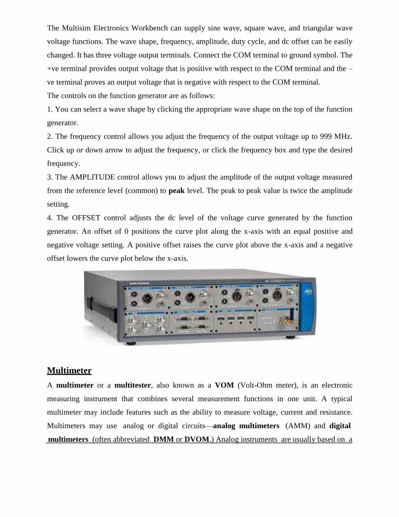
The Multisim Electronics Workbench can supply sine wave, square wave, and triangular wave
voltage functions. The wave shape, frequency, amplitude, duty cycle, and dc offset can be easily
changed. It has three voltage output terminals. Connect the COM terminal to ground symbol. The
+ve terminal provides output voltage that is positive with respect to the COM terminal and the –
ve terminal proves an output voltage that is negative with respect to the COM terminal.
The controls on the function generator are as follows:
1. You can select a wave shape by clicking the appropriate wave shape on the top of the function
generator.
2. The frequency control allows you adjust the frequency of the output voltage up to 999 MHz.
Click up or down arrow to adjust the frequency, or click the frequency box and type the desired
frequency.
3. The AMPLITUDE control allows you to adjust the amplitude of the output voltage measured
from the reference level (common) to peak level. The peak to peak value is twice the amplitude
setting.
4. The OFFSET control adjusts the dc level of the voltage curve generated by the function
generator. An offset of 0 positions the curve plot along the x-axis with an equal positive and
negative voltage setting. A positive offset raises the curve plot above the x-axis and a negative
offset lowers the curve plot below the x-axis.
Multimeter
A multimeter or a multitester, also known as a VOM (Volt-Ohm meter), is an electronic
measuring instrument that combines several measurement functions in one unit. A typical
multimeter may include features such as the ability to measure voltage, current and resistance.
Multimeters may use analog or digital circuits—analog multimeters (AMM) and digital
multimeters (often abbreviated DMM or DVOM.) Analog instruments are usually based on a

microammeter whose pointer moves over a scale calibrated for all the different measurements
that can be made; digital instruments usually display digits, but may display a bar of a length
proportional to the quantity being measured. A multimeter can be a hand-held device useful for
basic fault finding and field service work or a bench instrument which can measure to a very
high degree of accuracy. They can be used to troubleshoot electrical problems in a wide array of
industrial and household devices such as electronic equipment, motor controls, domestic
appliances, power supplies, and wiring systems.
Power Supply
A power supply is a device that supplies electric power to one or more electric loads. The term
is most commonly applied to devices that convert one form of electrical energy to another,
though it may also refer to devices that convert another form of energy (mechanical, chemical,
solar) to electrical energy. A regulated power supply is one that controls the output voltage or
current to a specific value; the controlled value is held nearly constant despite variations in either
load current or the voltage supplied by the power supply's energy source.
Every power supply must obtain the energy it supplies to its load, as well as any energy it
consumes while performing that task, from an energy source

Active Elements & Passive Elements
"The elements within a circuit will either control the flow of electric energy or respond to it.
Those elements which control the flow of electric energy are known as active elements and those
which dissipate or store the electric energy are passive elements."
"The three linear passive elements are the Resistor, the Capacitor and the Inductor. Examples of
non-linear passive devices would be diodes, switches and spark gaps. Examples of active devices
are Transistors, Triacs, Varistors, Vacuum Tubes, relays, solenoids and piezo electric devices."
Bread Board
A breadboard (protoboard) is a construction base for prototyping of electronics. The term is
commonly used to refer to solderless breadboard (plugboard). Because the solderless breadboard
does not require soldering, it is reusable. This makes it easy to use for creating temporary
prototypes and experimenting with circuit design.
4. RESULTS AND DISCUSSION:
Study of lab equipments- CRO, Multimeter, Function Generator, Power supply- Active, and
Passive Components & Bread Board has been studied successfully.

5. PRE EXPERIMENT Q.B:
Q1. What is CRO?
Ans. The oscilloscope is one of the most important electronic instruments available for making
circuit measurements. It displays a curve plot of time-varying voltage on the oscilloscope screen.
Q2. What do you mean by active element and passive element ?
Ans. "The elements within a circuit will either control the flow of electric energy or respond to
it. Those elements which control the flow of electric energy are known as active elements and
those which dissipate or store the electric energy are passive elements."
6. POST EXPERIMENT Q.B:
Q1. What is multimeter?
Ans. A multimeter also known as a VOM (Volt-Ohm meter), is an electronic measuring
instrument that combines several measurement functions in one unit. A typical multimeter may
include features such as the ability to measure voltage, current and resistance.
Q2. What is function generator?
Ans. The function generator is a voltage source that supplies different time-varying voltage
functions. The Multisim Electronics Workbench can supply sine wave, square wave, and
triangular wave voltage functions. The wave shape, frequency, amplitude, duty cycle, and dc
offset can be easily changed. It has three voltage output terminals.

AIM:- Preparation of layout and artwork layout planning.
LAYOUT PLANNING:-
1. Depending on the accuracy required artwork should be produced at a ratio of 1:1 or 4:1.
2. Use of grid system in layout and artwork design is a commonly accepted practice. Use of
grid gives more convenience in placement of components and conductors.
3. Selection of Board type-single sided.
4. MATERIAS AND AIDS:
(a) Simple approach and sketching of components.
(b) Layout sketching with puppets.
5. To prepare each and every PCB layout as viewed from component side.
6. Unless and unstill absolutely cleared circuit diagram is available. Startingly the designing
of layout is not possible.
7. Complete the layout work and start with interconnection.
8. Develop the layout in direction of single flow.
9. Among the components the longer one is placed first then the space in between is filled
with smaller one.
10. Design and interconnection can be done by pencil line.
GENERAL ARTWORK RULE:-
1. In PCB artwork higher conductor density is an established practice.
2. To run the conductors on one side in given direction.
3. Where conductors have to be placed in other direction preference should be given to 48
direction or 30/60 direction.
4. It is a good rule, to begin and end the conductors in solder pad.
5. Where one or several conductors have to pass between pads or other conducting carrier,
spacing has to be equally distributed.
COMPONENTS POLARITY IDENTIFICATION:-
It is very essential when artwork is completed, a through check is carried out to prepare and to
prove its exact correspondence with circuit diagram.
Dev Bhoomi Institute Of Technology
Department of Electronics and Communication
Engineering
LABORATORY
MANUAL
PRACTICAL INSTRUCTION SHEET
EXPERIMENT NO. 3 ISSUE NO. : ISSUE DATE:
REV. NO. : REV. DATE :
PAGE: 2
LABORATORY Name & Code: PCB LAB PEC-452 SEMESTER: IV

DOCUMENTATION:-
1. Circuit diagram.
2. Legend.
3. Artwork
4. Drill Problem.
5. Soldier masks.
6. Green masks.
7. Component layout.
8. Component list.
POST-QUESTIONS:-
What are the printers used for Artwork?
What is the ratio required for Artwork design?

OBJECT:- Preparation of Negative from the film.
APPARATUS REQUIRED:-
1. A developer (Sodium Carbonate).
2. B developer (Butyl cell solution).
3. Fixer.
4. Motor.
5. Photo-cure machine.
PROCESS:-
Draw the circuit on transparency i.e. Artwork with error proof.
EXPOSURE TIME:-
Expose the lith film together with the transparent sheet for 5sec.
DEVELOPMENT:-
Use a development tray which is large enough to enable film handling with care. Put
sufficient developer in the tray so that the film can get completely covered with it. Now
all the handling of the film should be done by touching only the corners.
To start a development Procedure Slide the exposed film sheet with emulsion
down through the solution only. Start immediately to lift the tray rotationally each side by
about 2cm.
STOPBATH:-
After development is over the film is gripped on one edge and lifted the developing tray
for 3 sec. which enable the excess developer to draw .Now immediately thereafter the
film is immersed into the stop bath always with emulsion side. Upward to mechanical
damages on the softened emulsion. The stop bath stops effectively the development
action.
FIXING BATH:-
Dev Bhoomi Institute Of Technology
Department of Electronics and Communication
Engineering
LABORATORY
MANUAL
PRACTICAL INSTRUCTION SHEET
EXPERIMENT NO. 4 ISSUE NO. : ISSUE DATE:
REV. NO. : REV. DATE :
PAGE: 2
LABORATORY Name & Code: PCB LAB PEC-452 SEMESTER: IV

The emulsion is properly fix after in the fixing solution for twice the time, it takes for
the milky appearance to clear completely.
FILM WASHING:-
After all underdeveloped silver halides have been removed the emulsion is steel
saturated with the chemicals of the fixing bathe and some desolved silver compound. If
they are not removed by washing so they will slowly decompose and attack the image,
causing stain and faided film.
The effectiveness of washing can be greatly improved if the film sheet after fixing, gets a
brief water rinse under the tap to remove the excess fixing solution which otherwise
would contaminated the washing tank.
DRYING:-
After washing, a dip in a wetting agent is the valuable aid for the drying process. For good
results, drying could take place slowly at room temperature.
RESULT:-
Negative is prepared according to the PCB circuit.
PRECAUTIONS:-
Circuit on the transparency should be drawn neat and clean.
Process should be done in the absence of sodium (yellow).
POST-QUESTIONS:-
What are the steps involved in the process of making up of negative from the film?
What are the dimensions of Proto-Contact PCB (Artwork film maker)?
OBJECT:- Principle of a simple PCB.
APPARATUS REQUIRED:-
1. Photo-resist slip coating machine.
2. U.V exposer unit.
3. Photo developer dye machine.
4. Photo curing machine (oven).
THEORY:-
The manual artwork PCB design is the method used by most manufacturing of PCB with this
method extremely accurate, high density PCB can be constructed. This artwork is then
Photographed to produce a negative which can be used with sensitized printed circuit. Exposing
of the negative by contact with coated circuit board is done first and then developing and other
process are required for a PCB.
PROCESS:-
1. Clean the laminate:-Before the metal surface is coating with crescent photoresist. Clean
surface thoroughly so as to make a completely free of physical and chemical continuation.
2. Coating the laminate:-Crescent Photo-resist can apply precisely and economically be using
a dipping process, done by a photo-resist to coats.
3. Thinner:-The thinner is used to dilute the photo-resist as it tends to get the thick during non-
use. The use of thinner will depend upon the method of coating.
4. Prefacing:-After coating the laminate allow it to dry naturally for 5 min. this helps to
evaporate the solvents completely.
5. Exposer:-The coated laminate is normally exposed in contact with photographic. Negative
and Positive crescent photo-resist is sensitive to U.V radiation and therefore U.V tube based U.V
Dev Bhoomi Institute Of Technology
Department of Electronics and Communication
Engineering
LABORATORY
MANUAL
PRACTICAL INSTRUCTION SHEET
EXPERIMENT NO. 5 ISSUE NO. : ISSUE DATE:
REV. NO. : REV. DATE :
PAGE: 2
LABORATORY Name & Code: PCB LAB PEC-452 SEMESTER: IV

exposer can be used for exposer.
6. Development:-The exposed plate should be placed into the solvents based developer. This
will remove unexposed area of the photo-resist and will produce colourless resist image which
has plastic like appearance.
7. Washing:-Immediately after developer is over, wash it on running water of natural pH. After
washing and drying, dying is carried out to improve the visibility of image.
8. Drying the Image:-Immense the dried that plate in the dye developer bath. The surface of
the board is coloured with the dye developer. The board is put under the running water of neutral
pH, in order to wash off the dye stain from unexposed area, which result into a clean dyed image
of photo-resist and the dry.
9. Post curing:-The post-baked surface will be stronger than the unbaked one. This process
can be done on PCB curing machine.
RESULT:-
After this process, circuit resist has left on required part of PCB and now coated or unprotected
metal may be etched in etching solution to prepare PCB.
PRECAUTIONS:-
Worktable, apparatus, tanks, traces should be completely free from dust and dirt.
Use of thinner should be done carefully.
POST-QUESTIONS:-
What are the main apparatus used in the principle of PCB?
What is the role of thinner in PCB?

OBJECT:- Etching and Drilling of PCB.
APPARATUS REQUIRED:-
Etching machine
Ferric chloride
Drilling Machine
THEORY:-
This is an important and critical step in chemical processing of direct etched boards. Although
basically this operation of chemical removal of unwanted copper portion ferric chloride is widely
used for copper and copper alloys. He removed the unwanted copper from laminate by photo
etching machine. In this machine laminate put in tank filled with chemical ferric chloride which
is agitated by a pump and a heater. The heater helps the chemical become to warm and help it to
etch PCB faster.
Fresh chemical is available to the surface area that dissolved the metal from surface is rinsed
away simultaneously. Sensor is provided for maintaining temperature.
DRILLING:-
After etching, drilling of PCB is done for making holes on the conductor pattern for inserting
the component leads to the solder of PCB.
RESULTS:-
PCB is fabricated according to the required circuit board.
PRECAUTIONS:-
Clean and etch the board after completion of etching.
Drilling should be done carefully.
POST-QUESTIONS:-
What is the work of drilling Machine?
What is the role of sensor?
Dev Bhoomi Institute Of Technology
Department of Electronics and Communication
Engineering
LABORATORY
MANUAL
PRACTICAL INSTRUCTION SHEET
EXPERIMENT NO. 6 ISSUE NO. : ISSUE DATE:
REV. NO. : REV. DATE :
PAGE: 1
LABORATORY Name & Code: PCB LAB PEC-452 SEMESTER: IV

OBJECT: - Preparation and mounting components.
Components lead Preparation: Bending of axial components leads is done in a manner to
generate an optimum detection of the component. All the PCB by a minimum of stress is
introduced on the solder joint. In no case, there should be damage to the component or it leads to
cost while bending of leads any stress on components where they directly come out from the
component body has to be avoided.
Component Mounting: Components are basically mounted only on one side of the board.
Component orientation can be vertical or horizontal but uniform reading direction should be
maintained. The uniformity in orientation of odorized components is determined during the PCB.
PROCEDURE:-
Attach the electronic components in configuration of bridge rectifier.
Check the primary and secondary side of transformer and connect secondary of
transformer as input of bridge rectifier.
RESULT:-
All required components are properly mounted on PCB.
POST-QUESTIONS:-
What should not be recommended in mounting the PCB Components?
What is the role of transformer in mounting the PCB components?
Dev Bhoomi Institute Of Technology
Department of Electronics and Communication
Engineering
LABORATORY
MANUAL
PRACTICAL INSTRUCTION SHEET
EXPERIMENT NO. 7 ISSUE NO. : ISSUE DATE:
REV. NO. : REV. DATE :
PAGE: 1
LABORATORY Name & Code: PCB LAB PEC-452 SEMESTER: IV
Related Documents