DSE-F501-64C (Rev 06/18/18) Page 1 of 13 Detroit Speed, Inc. RS Electric Headlight Door Kit 1968 Camaro P/N: 122002 Figure 1 Item QTY Description 1 1 LH Actuator w/Bracket and Linkage 2 1 RH Actuator w/Bracket and Linkage 3 1 Headlight Door Control Module 4 1 Harness Assembly 5 3 Rubber Grommets 6 10 Nylon Wire Ties 7 1 Instructions/Inner Fender Template (1) (3) (2) (4) (5)

Welcome message from author
This document is posted to help you gain knowledge. Please leave a comment to let me know what you think about it! Share it to your friends and learn new things together.
Transcript

DSE-F501-64C (Rev 06/18/18) Page 1 of 13
Detroit Speed, Inc.
RS Electric Headlight Door Kit 1968 Camaro P/N: 122002
Figure 1
Item QTY Description
1 1 LH Actuator w/Bracket and Linkage
2 1 RH Actuator w/Bracket and Linkage
3 1 Headlight Door Control Module
4 1 Harness Assembly
5 3 Rubber Grommets
6 10 Nylon Wire Ties
7 1 Instructions/Inner Fender Template
(1)
(3)
(2)
(4)
(5)

DSE-F501-64C (Rev 06/18/18) Page 2 of 13
Thank you for your purchase of Detroit Speed’s RS Headlight Door Kit. This kit replaces the stock vacuum actuators on an RS headlamp equipped 1968 Camaro. When installed, this kit will operate the headlight doors smoothly and reliably. The complicated, failure prone, and bulky vacuum accessories can all be eliminated. Vehicles with large cams with low vacuum signals will also benefit from this system since they are electronically controlled. Many convenience features are integrated into this system. When the headlight switch is pulled to the “park” position, the park lamps illuminate. The headlights stay off and the headlight doors remain closed. When the switch is pulled to the “headlamps” position, the park lights stay on, the headlight doors open, and the headlamps illuminate. When the switch is pushed back to the “park” position, the headlamps turn off, but the headlamp doors remain open. This is useful to clean or service the headlamps since the doors will be open and the lenses cool. When switched to the “off” position, the park lights go out and the headlight doors close. The module that is included with the RS Electric Headlight Door Kit has a unique integrated failsafe protection mode. The module is designed to protect itself from damage due to a short circuit in your wiring system. If a short exists, the module will click continuously. This means a short has been detected and the module has entered into its fail safe mode. For the system to operate again, correction of the short circuit is required followed by resetting the module. To reset the module, remove the fuse from the main power wire for 10 seconds and then reinstall the fuse. If the clicking reoccurs, the short has not been repaired and needs further investigation. The actuators are pressure sensitive to reduce the chance of personal injury or damage to the vehicle in the event that something is caught in the door during operation. If the door comes in contact with a foreign object, it will stop its operation. The lights will need to be cycled on and off to reset the mechanism. NOTE: The pitman arms on the actuators will not be able to be moved by hand as that could cause permanent damage to the actuators. The pitman arms are clocked in the correct position for installation at DSE and will cycle closed once power is introduced to the system. DSE has gone to great lengths to provide you with the highest quality, best engineered product available with straightforward installation requiring minimal modification to your vehicle. IMPORTANT: This kit is designed to work with properly installed and adjusted RS headlight doors. This system will not work correctly with doors that do not have the stops adjusted properly. The doors must open and close without binding or resistance. Because the system is pressure sensitive, binding or sticking RS door assemblies will cause the actuators to stop prematurely. DSE suggests lubricating all pivot points. Make sure that the main pivot shaft and the bellcrank are not overtightened.
The battery must be disconnected before starting the installation.
I. Mount the RS headlight module
1. Locate brake pedal support bracket under the driver’s side dash spanning from the brake pedal assembly to the steering column support attachment. Mock up the module and mounting plate and locate the bolt holes on support bracket with a marker or scribe as shown in Figure 2 on the next page. The module should be positioned towards the driver’s side.

DSE-F501-64C (Rev 06/18/18) Page 3 of 13
Figure 2 – Locating the Holes
2. Using the marks located in the previous step, drill two 5/16” diameter holes in the support
bracket. Slide the two included U-nuts over the drilled holes. One U-nut is larger than the other. This is to compensate for the angle on the support bracket. Make sure the holes are drilled so that the U-nuts can be properly installed. Attach the module mounting plate to the support bracket using the two included black oxide ¼” diameter bolts and washers. The finished, mounted module assembly is shown below in Figure 3.
Figure 3 – Module Mounted in Place

DSE-F501-64C (Rev 06/18/18) Page 4 of 13
II. Install the Module Wiring
1. Remove the headlight switch from the dash. This can be simplified by removing the Astro Vent below the switch as shown in Figure 4.
Figure 4 – Removing the Astro Vent
2. The headlamp switch can then be removed from the dash through this opening. See Figure 5.
Figure 5 – Accessing the Headlamp Switch
3. Remove the connector from the headlight switch. Locate and mark the blue wire and remove
the terminal from the connector housing using a terminal removal tool or a small flat blade screwdriver. The blue wire is the 12 volt headlamp feed. See Figure 6 on the next page.

DSE-F501-64C (Rev 06/18/18) Page 5 of 13
Figure 6 – Locating the Blue Wire
4. Slide the included black male connector over the blue wire terminal which was just removed
from headlight harness connector as seen in Figure 7. Connect the stock blue wire to white female connector (blue wire) on module pigtail harness.
Figure 7 – Inserting Blue Wire into Provided Connector
5. Now, locate the blue and brown wires on the supplied module pigtail. Slide the blue wire/female
terminal into the cavity in the headlight switch connector where you removed the stock blue wire. Slide the female terminal on the brown wire into the empty cavity shown in the picture. See Figure 8 on the next page.
Headlight Signal (Blue Wire)
DSE-F501-64C (Rev 06/18/18) Page 6 of 13
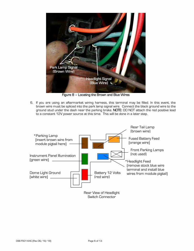
Figure 8 – Locating the Brown and Blue Wires
6. If you are using an aftermarket wiring harness, this terminal may be filled. In this event, the
brown wire must be spliced into the park lamp signal wire. Connect the black ground wire to the ground stud under the dash near the parking brake. NOTE: DO NOT attach the red positive lead to a constant 12V power source at this time. This will be done in a later step.
Headlight Signal (Blue Wire)
Park Lamp Signal (Brown Wire)
Rear View of Headlight Switch Connector
Fused Battery Feed (orange wire)
*Headlight Feed (remove stock blue wire terminal and install blue wires from module pigtail)
*Parking Lamp (insert brown wire from module pigtail here)
Instrument Panel Illumination (green wire)
Dome Light Ground (white wire)
Battery 12 Volts (red wire)
Front Parking Lamps (not used)
Rear Tail Lamp (brown wire)

DSE-F501-64C (Rev 06/18/18) Page 7 of 13
NOTE: The 2 leads for the parking lamp (numbered 3 and 5) will need to be bridged together in order for this kit to work correctly (Figure 9). If your headlight switch does not have a bridge you will need to jump the 2 leads together.
Figure 9 – Headlight Switch
III. Install the Actuator Harness
1. Drill a 7/16” diameter hole near the firewall bulkhead to pass the actuator leads through. Use the
included firewall grommet to protect the wiring.
2. Route the wires along the inner fender well along the stock headlight harness toward the front of the vehicle. Drill a 7/16” diameter hole in the inner fenderwell area to pass harness leads through. We suggest drilling the hole adjacent to the turn signal wire grommet. Insert the supplied rubber grommets and feed the two wires through toward the actuator. The yellow and orange wires should pass through the driver’s side inner wheelhouse. Route the green and purple wires along the factory harness underneath the core support to the passenger side inner wheelhouse. Pass the green and purple wires through the grommet. Secure the harness with the supplied nylon ties.
3. On the underside of the wheel house, insert the terminal ends into the supplied weatherpack
connectors (Figure 10). On the connector body, the cavities are labeled “A” and “B.” On the driver’s side, the yellow wire should be inserted into the cavity labeled “A” and the orange wire into cavity “B”. On the passenger side, insert the purple wire into cavity “A” and the green wire into the cavity labeled “B.” Terminals should “snap” into place. Once the terminals are installed, snap the cover over the wires.
DSE 1968 Camaro RS Headlight Door Actuator Wiring
Driver Side
Harness Yellow Wire Connector Cavity “A” Door Actuator Black Wire
Cavity “A” Yellow to Black Wire
Harness Orange Wire Connector Cavity “B” Door Actuator Blue Wire
Cavity “B” Orange to Blue Wire
Passenger Side
Harness Purple Wire Connector Cavity “A” Door Actuator Black Wire
Cavity “A” Purple to Black Wire
Harness Green Wire Connector Cavity “B” Door Actuator Blue Wire
Cavity “B” Green to Blue Wire
Figure 10 – Connect Harness to Actuators
Bridge #3 & #5

DSE-F501-64C (Rev 06/18/18) Page 8 of 13
IV. Install Actuators and Linkage NOTE: A template has been attached to assist you in locating where to cut holes in your stock inner fenders to install RS headlight assemblies in vehicles that were not originally RS headlight equipped. Some aftermarket inner fenders may also need this template to locate the holes for the RS headlight assemblies. Cut the template from the sheet and align it as described on the template. The template can be used on both sides by flipping it over. After cutting out the template, align it to the front edge of the inner fender and the existing holes. Mark the new holes on the inner fender and cut out the appropriate holes.
1. Remove the battery and battery tray.
2. Under the vehicle, if the headlight door vacuum actuator system is still installed, remove it from the
vehicle. The vacuum tanks, actuators, hoses and valves will not be needed.
3. NOTE: If there is an over-center spring installed on the bellcrank assembly, it must be removed. It is located behind the headlight bucket. The headlight must be removed to gain access to the spring. Right angle pliers and a screwdriver will be helpful to remove the spring. Be sure to wear proper eye protection. If the spring cannot be removed, the headlight bucket assembly will have to be removed from the car.
4. Locate the two bolts on the passenger side that attach the inner wheelhouse to the core support underneath the front fender area. Figure 11 shows the location of the bolts.
Figure 11 – Location of Core Support Bolts
Wheelhouse to Core Support Bolts
RS Bellcrank Assembly

DSE-F501-64C (Rev 06/18/18) Page 9 of 13
5. Remove these two bolts and position the actuator and bracket. The motor/wire pigtail should point towards the outside of the car. The holes are slotted so that the actuator assembly can be aligned with the bellcrank of the RS headlight assembly. Reinstall the two bolts to attach the actuator to the vehicle as shown in Figure 12 on the next page. NOTE: Position the actuator/bracket so that the pitman arm can pass underneath the splash guard bracket without contact. If you plan on using the splash guard you will need to trim it as necessary to clear the pitman arm and/or red override knob.
Figure 12 – Bottom View of Actuator
6. Insert one of the two supplied nylon bushings into the bellcrank of the RS headlight assembly from
the bottom as shown in Figure 13.
Figure 13 – Installing Bushing in Pitman Arm
Front of Vehicle
Outside of Vehicle

DSE-F501-64C (Rev 06/18/18) Page 10 of 13
7. Install the linkage to connect the actuator to the bellcrank. Install with the supplied washers and locknut. If the linkage does not reach the bellcrank, reposition the headlight door until they can be assembled. There is a red manual override knob shown in Figure 14 that can be turned to move the pitman arm to reach the bellcrank. NOTE: Do not attempt to move the pitman arms on the actuators by hand to attach the linkage as this could cause permanent damage to the actuators.
Figure 14
8. The pitman arms on the actuators are clocked at a position where the doors should be half way
open/closed when the linkage is attached. The installed assembly can be seen below in Figures 15 and 16.
Figures 15 & 16 – Actuators Installed
9. Connect the harness to the actuators and make sure the wires are routed away from moving
parts or sharp edges. Use the supplied nylon wire ties to secure the harness.
10. To complete the driver side actuator installation, follow the above instructions as the installation is the same as the passenger side.
11. Reinstall the battery and tray.
Override
Knob
Front of Vehicle
Front of Vehicle
Outside of Vehicle
Outside of Vehicle

DSE-F501-64C (Rev 06/18/18) Page 11 of 13
V. Powering the System
1. Before powering the system, double-check all wiring connections for continuity using a multimeter. Incorrect wiring can cause serious damage to the system.
2. Attach a 12V constant power source to the module. Make sure the 10 amp fuse is installed in
between the power source and the module. 3. Reconnect the battery. The system will cycle at this point and the doors should be in the closed
position.
4. Once the system has cycled, check the operation of the system by turning the headlamps on and off.
VI. Installation Complete
If you have any questions before or during the installation of this product please contact Detroit Speed Inc. at [email protected] or 704.662.3272
Legal Disclaimer: Detroit Speed, Inc. is not liable for personal, property, legal, or financial damages from the use or misuse of any product we sell. The purchaser is solely responsible for the safety and performance of these products. No warranty is expressed or implied.

DSE-F501-64C (Rev 06/18/18) Page 12 of 13
Headlight Switch Position Red Black Brown Blue Door Operation Light Operation
Off + 12 V Ground (- 12V) 0 V 0 V None None
Park + 12 V Ground (- 12V) 12 V 0 V None Park
Headlight + 12 V Ground (- 12V) 12 V 12 V Door Opens Park/Headlights
Park (after headlights on) + 12 V Ground (- 12V) 12V 0 V None (Door remains open w/headlights off) Park
Off + 12 V Ground (- 12V) 0 V 0 V Door Closes None
Condition Cause
Red Wire
Black Wire Ground
Brown Wire Park Lamp Feed
Blue Wire Headlight Feed
Orange Wire LH Actuator +
Yellow Wire LH Actuator -
Green Wire RH Actuator +
Purple Wire RH Actuator -
RS Headlight Troubleshooting
*looking from back side of connector
Doors only open or close partially.
Doors do not go through "power up" cycle.
One door opens faster/slower than the other.
On the driver's side, make sure the yellow wire is inserted into cavity "A" and the orange wire into cavity
"B" of the supplied connector body. The purple wire should be inserted into cavity "A" and the green wire
into cavity "B" of the supplied connector body for the passenger side. If the wires are terminated properly
and the problem still exists, reversing the wires on the offending actuator(s) will solve the problem.
Check voltages at red, black, blue, and brown wires as described in above chart. If voltages are consistent
with the chart, try disconnecting and reconnecting the red wire. If the doors do not operate or do not
attempt to operate at this point, double check that the actuator harness is plugged into the module and
the actuators. Check continuity between the actuator wires at the module pigtail and at the actuator
connector.
After all connections are made, connect the battery. The doors should go through a "power up" cycle. During this cycle, the doors will close. Anytime
the current source to the module is disconnected and reconnected, the doors will go through the "power up" cycle. The module features a failsafe
protection to protect the module from being shorted out. If a short exists, the module will beep and is followed by a series of clicks. This means a
short has been detected and the module has entered into its fail safe mode. For the system to operate again, correction of the short circuit is
required followed by resetting the module. To reset the module, remove the fuse from the main power wire for 10 seconds and then reinstall the fuse.
If the clicking reoccurs, the short has not been repaired and needs further investigation. The following chart shows the expected voltages at the
module input during typical operation. Use this to troubleshoot the wiring installation and headlight switch operation.
Wire Color
*If none of these suggestions solve your particular issue, please call Detroit Speed at (704) 662-3272.
Module Connector Pin-out (back of connector)
Module clicks continuously.
Doors do not operate at all.
One or both doors close when the headlight switch is
turned on. Door(s) open when the headlight switch is
turned off.
Constant 12V Battery Voltage
The module has entered into its failsafe mode. The module enters into this mode when it detects a short
in the system. To correct, determine and repair the short that exists in the system. To return the module
to its normal function, remove the 10 amp fuse for 10 seconds and reinstall the fuse. The system should
go through its "power up" cycle. If it does not or the clicking continues, a short still exists in the vehicles
electrical system and requires further investigation.
Most issues with door operation are due to headlight door assemblies that have too much resistance,
binding, or are out of adjustment. To check for correct operation of the module and actuators, disconnect
the linkages from the pitman arms. With nothing attached to the motor pitman arm, have another
person cycle the switch from off, to park, to headlight, and then back to off. The actuators should turn
approximately one complete revolution in one direction, stop, and then turn one revolution in the opposite
direction. If the actuators operate as described, intermittent problems are most likely due to doors that
have too much resistance opening and/or closing.
One door has more/less resistance than the other. Lubricate pivot points and adjust the tension of
fasteners at pivots points.
Make sure the battery voltage is over 11.5 V. A low battery condition can result in inoperable doors.
Check all connections. Make sure fuse is not blown and doors are not binding.
Red Black
BlueBrown
Purple
Orange
Green
Yellow

DSE-F501-64C (Rev 06/18/18) Page 13 of 13
Related Documents