Determining Tube Size for Hydraulic Systems Pressure lines - 25 ft./sec. or 7.62 meters/sec. Return lines - 10 ft./sec. or 3.05 meters/sec. Suction lines - 4 ft./sec. or 1.22 meters/sec. If you desire to use different velocities than the above, use one of the following formulae to determine the required flow diameter. Proper tube material, type and size for a given application and type of fitting is critical for efficient and trouble free operation of the fluid system. Selection of proper tubing involves choosing the right tube material, and determining the optimum tube size (0.0. and wall thickness). Proper sizing of the tube for various parts of a hydraulic system results in an optimum combination of efficient and cost effective performance. A tube that is too small causes high fluid velocity, which has many detrimental effects. In suction lines, it causes cavitation which starves and damages pumps. In pressure lines, it causes high friction losses and turbulence, both resulting in high pressure drops and heat generation. High heat accelerates wear in moving parts and rapid aging of seals and hoses, all resulting in reduced component life. High heat generation also means wasted energy, and hence, low efficiency. Too large of a tube increases system cost. Thus, optimum tube sizing is very critical. The following is a simple procedure for sizing the tubes. Step 1: Determine Required Flow Diameter Use Tables U13 and U14 to determine recommended flow diameter for the required flow rate and type of line. The table is based on the following recommended flow veloci- ties: OR Tube 1.0. (in.) = 0.64 Tube 1.0. (mm) = 4.61 Flow in GPM Velocity in fUsee. Flow in liters per minute Velocity in meters/sec. Step 2: Determine Tube 0.0. and Wall Thickness Using Tables U15 and U16, determine the tube 0.0. and wall thickness combination that satisfies the following two condi- tions: A. Has recommended design pressure equal to or higher - than maximum operating pressure. B. Provides tube 1.0. equal to or greater than required flow diameter determined earlier. Design pressure values in Tables U15 and U16 are based on the severity of service rating "A" (design factor of 4) in Table U10, and temperature derating factor of 1 in Table U11. If more severe operating conditions are involved, the values in Tables U15 and U16 should be multiplied by appropriate derating factors from Tables U1 0 and U11 before determining the tube 0.0. and wall thickness combination. Contact the Tube Fittings Division when in doubt. Allowable design stress levels and formula used to arrive at the design pressure values are given in the following chart. Values in Table U8 are for fully annealed tubing. Allowable Design Material Stress fo Design Tube and Type Factor of 4 at 72°F Specification Steel C-1 010 12,500 PSI SAE J356, J524, J525 Steel C-1 021 15,000 PSI SAE J2435, J2467 Steel, High SAE J2613, Strength Low Alloy 18,000 PSI J2614 (HSLA) Stainless Steel 18,800 PSI ASTM A213, 304 & 316 A249,A269 Alloy Steel C-4130 18,800 PSI ASTM A519 Copper, K or Y 6,000 PSI SAE J528, ASTM 875 Aluminum 6061-T6 10,500 PSI ASTM 8210 Monel, 400 17,500 PSI ASTM 8165 Table U8 - Design Stress Values Design Pressure Formula (LAME'S) P = S (_0_2 _- d_2_) where: 02 + d2 o = Outside diameter of tube, in d = Inside diameter of tube (D-2T), in P = Recommended design pressure, psi S = Allowable stress for design factor of 4, psi T = Tube wall thickness, in. Table U9 - Design Pressure Formula For thin wall tubes (DIT ~ 10) the following formula may be Used: P = 2ST/D

Welcome message from author
This document is posted to help you gain knowledge. Please leave a comment to let me know what you think about it! Share it to your friends and learn new things together.
Transcript
Determining Tube Sizefor Hydraulic Systems
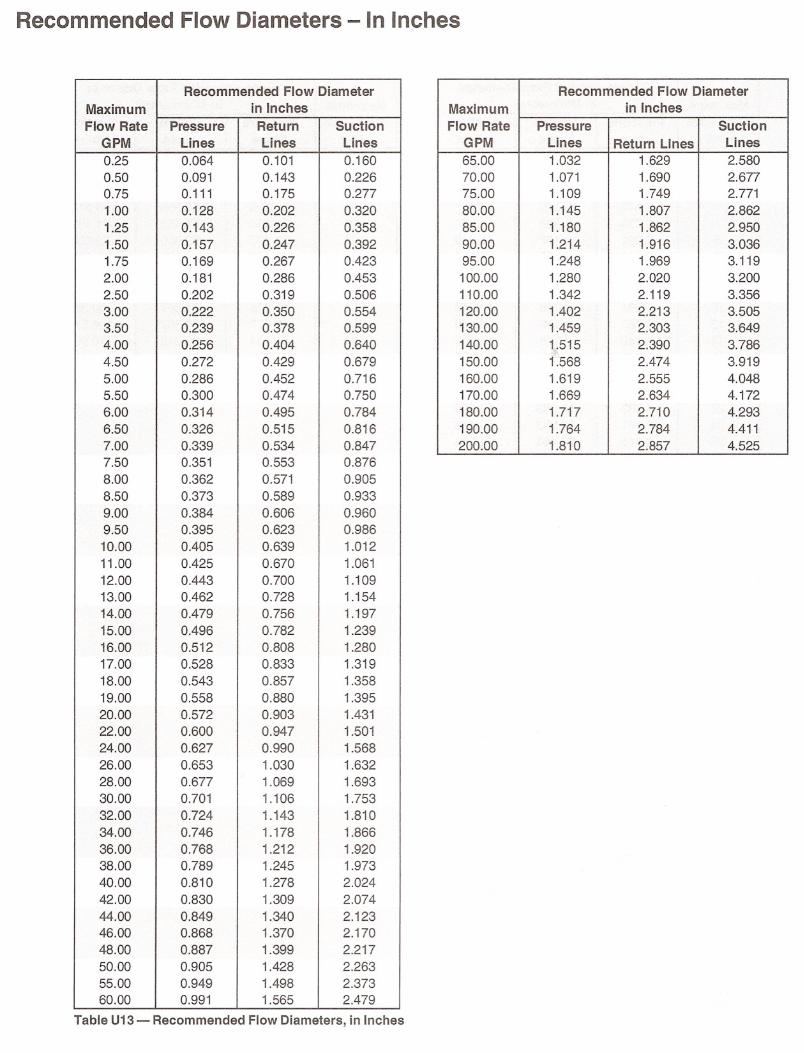
Pressure lines - 25 ft./sec. or 7.62 meters/sec.Return lines - 10 ft./sec. or 3.05 meters/sec.Suction lines - 4 ft./sec. or 1.22 meters/sec.
If you desire to use different velocities than the above, use oneof the following formulae to determine the required flow diameter.
Proper tube material, type and size for a given application andtype of fitting is critical for efficient and trouble free operation ofthe fluid system. Selection of proper tubing involves choosingthe right tube material, and determining the optimum tube size(0.0. and wall thickness).
Proper sizing of the tube for various parts of a hydraulic systemresults in an optimum combination of efficient and cost effectiveperformance.
A tube that is too small causes high fluid velocity, which hasmany detrimental effects. In suction lines, it causes cavitationwhich starves and damages pumps. In pressure lines, it causeshigh friction losses and turbulence, both resulting in highpressure drops and heat generation. High heat accelerateswear in moving parts and rapid aging of seals and hoses, allresulting in reduced component life. High heat generation alsomeans wasted energy, and hence, low efficiency.
Too large of a tube increases system cost. Thus, optimum tubesizing is very critical. The following is a simple procedure forsizing the tubes.
Step 1: Determine Required Flow Diameter
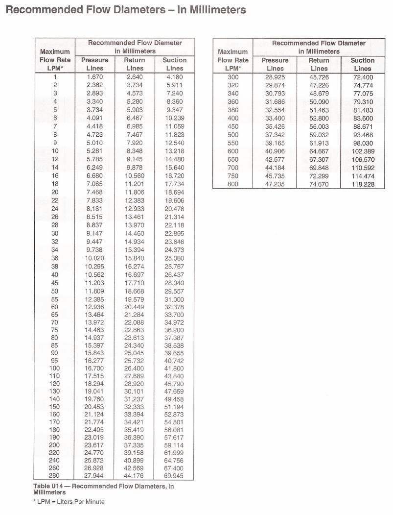
Use Tables U13 and U14 to determine recommended flowdiameter for the required flow rate and type of line.
The table is based on the following recommended flow velocities:
OR
Tube 1.0. (in.) = 0.64
Tube 1.0. (mm) = 4.61
Flow in GPM
Velocity in fUsee.
Flow in liters per minute
Velocity in meters/sec.
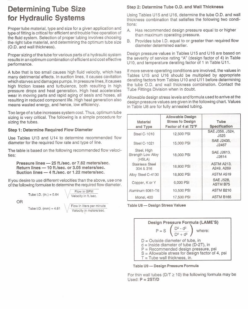
Step 2: Determine Tube 0.0. and Wall Thickness
Using Tables U15 and U16, determine the tube 0.0. and wallthickness combination that satisfies the following two conditions:
A. Has recommended design pressure equal to or higher than maximum operating pressure.
B. Provides tube 1.0. equal to or greater than required flowdiameter determined earlier.
Design pressure values in Tables U15 and U16 are based onthe severity of service rating "A" (design factor of 4) in TableU10, and temperature derating factor of 1 in Table U11.
If more severe operating conditions are involved, the values inTables U15 and U16 should be multiplied by appropriatederating factors from Tables U1 0 and U11 before determiningthe tube 0.0. and wall thickness combination. Contact the
Tube Fittings Division when in doubt.
Allowable design stress levels and formula used to arrive at thedesign pressure values are given in the following chart. Valuesin Table U8 are for fully annealed tubing.
Allowable DesignMaterial
Stress fo DesignTube
and Type
Factor of 4 at 72°FSpecification
Steel C-1 010
12,500 PSISAE J356, J524,
J525Steel C-1 021
15,000 PSISAE J2435,
J2467Steel, HighSAE J2613,Strength Low Alloy
18,000 PSIJ2614(HSLA) Stainless Steel18,800 PSI
ASTM A213,
304 & 316A249,A269
Alloy Steel C-4130
18,800 PSIASTM A519
Copper, K or Y
6,000 PSISAE J528,
ASTM 875Aluminum 6061-T6
10,500 PSIASTM 8210
Monel, 400
17,500 PSIASTM 8165
Table U8 - Design Stress Values
Design Pressure Formula (LAME'S)
P = S (_0_2 _-d_2_) where:02 + d2
o = Outside diameter of tube, ind = Inside diameter of tube (D-2T), inP = Recommended design pressure, psiS = Allowable stress for design factor of 4, psiT = Tube wall thickness, in.
Table U9 - Design Pressure Formula
For thin wall tubes (DIT ~ 10) the following formula may beUsed: P = 2ST/D
Recommended Flow Diameters - In Inches
Recommended Flow DiameterMaximum
in Inches
Flow Rate
PressureReturnSuctionGPM
LinesLinesLines
0.25
0.0640.1010.1600.50
0.0910.1430.2260.75
0.1110.1750.2771.00
0.1280.2020.320
1.25
0.1430.2260.3581.50
0.1570.2470.3921.75
0.1690.2670.4232.00
0.1810.2860.4532.50
0.2020.3190.5063.00
0.2220.3500.5543.50
0.2390.3780.5994.00
0.2560.4040.6404.50
0.2720.4290.6795.00
0.2860.4520.7165.50
0.3000.4740.7506.00
0.3140.4950.7846.50
0.3260.5150.8167.00
0.3390.5340.8477.50
0.3510.5530.8768.00
0.3620.5710.9058.50
0.3730.5890.9339.00
0.3840.6060.9609.50
0.3950.6230.98610.00
0.4050.6391.01211.00
0.4250.6701.06112.00
0.4430.7001.10913.00
0.4620.7281.15414.00
0.4790.7561.19715.00
0.4960.7821.23916.00
0.5120.8081.28017.00
0.5280.8331.31918.00
0.5430.8571.35819.00
0.5580.8801.39520.00
0.5720.9031.43122.00
0.6000.9471.50124.00
0.6270.9901.56826.00
0.6531.0301.63228.00
0.6771.0691.69330.00
0.7011.1061.75332.00
0.7241.1431.81034.00
0.7461.1781.86636.00
0.7681.2121.92038.00
0.7891.2451.97340.00
0.8101.2782.02442.00
0.8301.3092.07444.00
0.8491.3402.12346.00
0.8681.3702.17048.00
0.8871.3992.21750.00
0.9051.4282.26355.00
0.9491.4982.37360.00
0.9911.5652.479
Table U13 - Recommended Flow Diameters, in Inches
Recommended Flow DiameterMaximum
in Inches
Flow Rate
Pressure SuctionGPM
LinesReturn LinesLines
65.00
1.0321.6292.58070.00
1.0711.6902.67775.00
1.1091.7492.77180.00
1.1451.8072.86285.00
1.1801.8622.95090.00
1.2141.9163.03695.00
1.2481.9693.119100.00
1.2802.0203.200110.00
1.3422.1193.356120.00
1.4022.2133.505130.00
1.4592.3033.649140.00
1.5152.3903.786
150.001.5682.4743.919
160.001.6192.5554.048
170.001.6692.6344.172
180.001.7172.7104.293
190.001.7642.7844.411
200.001.8102.8574.525

Inch Tube Pressure Ratings
Inch Tubes*
Design Pressure(4:1 Design Factor), PSIStai nlessTube
WallTube Steel
a.D.
Thick.I.D.SteelSteel304 & 316,
(in.)
(in.)(in.)101010214130, HSLACopper0.125
0.0100.1052150260032501050
0.125
0.0200.08546005500690022000.125
0.0280.069665080001000032000.125
0.0350.0558450101501270040500.188
0.0100.1681400170021006500.188
0.0200.1482950355044501400
0.188
0.0280.13242505100640020500.188
0.0350.11854506550820026000.188
0.0490.090785094001180037500.250
0.0200.2102150260032501050
0.2500.0280.1943100370046501500
0.2500.0350.1803950475059501900
0.250
0.0490.15257506900865027500.250
0.0580.13469008300104003300
0.250
0.0650.120780093501175037500.250
0.0830.0849950119501500048000.313
0.0200.2731700205025508000.313
0.0280.2572450295036501150
0.3130.0350.2433100370046501500
0.3130.0490.2154500540067502150
0.313
0.0580.1975400650081502600
0.3130.0650.1836150740092502950
0.313
0.0720.16968508200103503300
0.3130.0830.14780009600120503850
0.313
0.0950.1239150110001380044000.375
0.0200.3351400170021006500.375
0.0280.319200024003000950
0.375
0.0350.30525503050385012000.375
0.0490.2773650440055501750
0.375
0.0580.25944505350665021000.375
0.0650.24550006000755024000.375
0.0720.2315600670084502700
0.375
0.0830.20965507900990031500.375
0.0950.185760091001145036500.375
0.1090.1578750105001320042000.500
0.0280.4441500180022007000.500
0.0350.4301850220028009000.500
0.0490.40227003250405013000.500
0.0580.38432503900485015500.500
0.0650.37036504400550017500.500
0.0720.35641004900615019500.500
0.0830.33448005750720023000.500
0.0950.31055506650835026500.500
0.1090.28264507750975031000.500
0.1200.260720086501080034500.500
0.1340.232805096501215038500.500
0.1480.2048950107501345043000.500
0.1880.1241105013250166005300
* See Table U8 for tube specifications.
Table U15 -Inch Tube Pressure Ratings
Inch Tubes*
Design Pressure(4:1 Design Factor), PSIStainlessTube
WallTube Steel
a.D.
Thick.J.D.SteelSteel304 & 316,
(in.)
(in.)(in.)101010214130, HSLACopper0.625
0.0280.5691150140017505500.625
0.0350.5551500180022007000.625
0.0490.52721002500320010000.625
0.0580.50925503050380012000.625
0.0650.49528503400430013500.625
0.0720.48132003850480015500.625
0.0830.45937504500565018000.625
0.0950.43543505200655021000.625
0.1090.40750506050760024500.625
0.1200.38556006700845027000.625
0.1340.35763507600955030500.750
0.0350.6801200145018506000.750
0.0490.6521750210026008500.750
0.0580.63421002500315010000.750
0.0650.62023502800355011500.750
0.0720.60626503200395012500.750
0.0830.5843050365046001450
0.7500.0950.5603550425053501700
0.7500.1090.5324150500062002000
0.7500.1200.5104600550069002200
0.7500.1340.4825200625078002500
0.7500.1480.4545800700087002800
0.7500.1880.37475009000113003600
0.8750.0350.805105012501550500
0.8750.0490.777150018002200700
0.8750.0580.759175021002650850
0.8750.0650.745200024003000950
0.8750.0720.7312200265033501050
0.8750.0830.7092600310039001250
0.8750.0950.6853000360045001450
0.8750.1090.6573500420052501650
0.8750.1200.6353900470058501850
0.8750.1340.6074400530066002100
0.8750.1480.5794900590073502350
1.0000.0350.93090011001350450
1.0000.0490.902130015501950600
1.0000.0580.884155018502300750
1.0000.0650.870175021002600850
1.0000.0720.856195023502900950
1.0000.0830.8342250270034001100
1.0000.0950.8102600310039001250
1.0000.1090.7823000360045501450
1.0000.1200.7603350400050501600
1.0000.1340.7323800455057001800
1.0000.1480.7044200505063502000
1.0000.1560.6884450535067002150
1.0000.1880.6245500660082502650
1.0000.2200.5606550785098003150
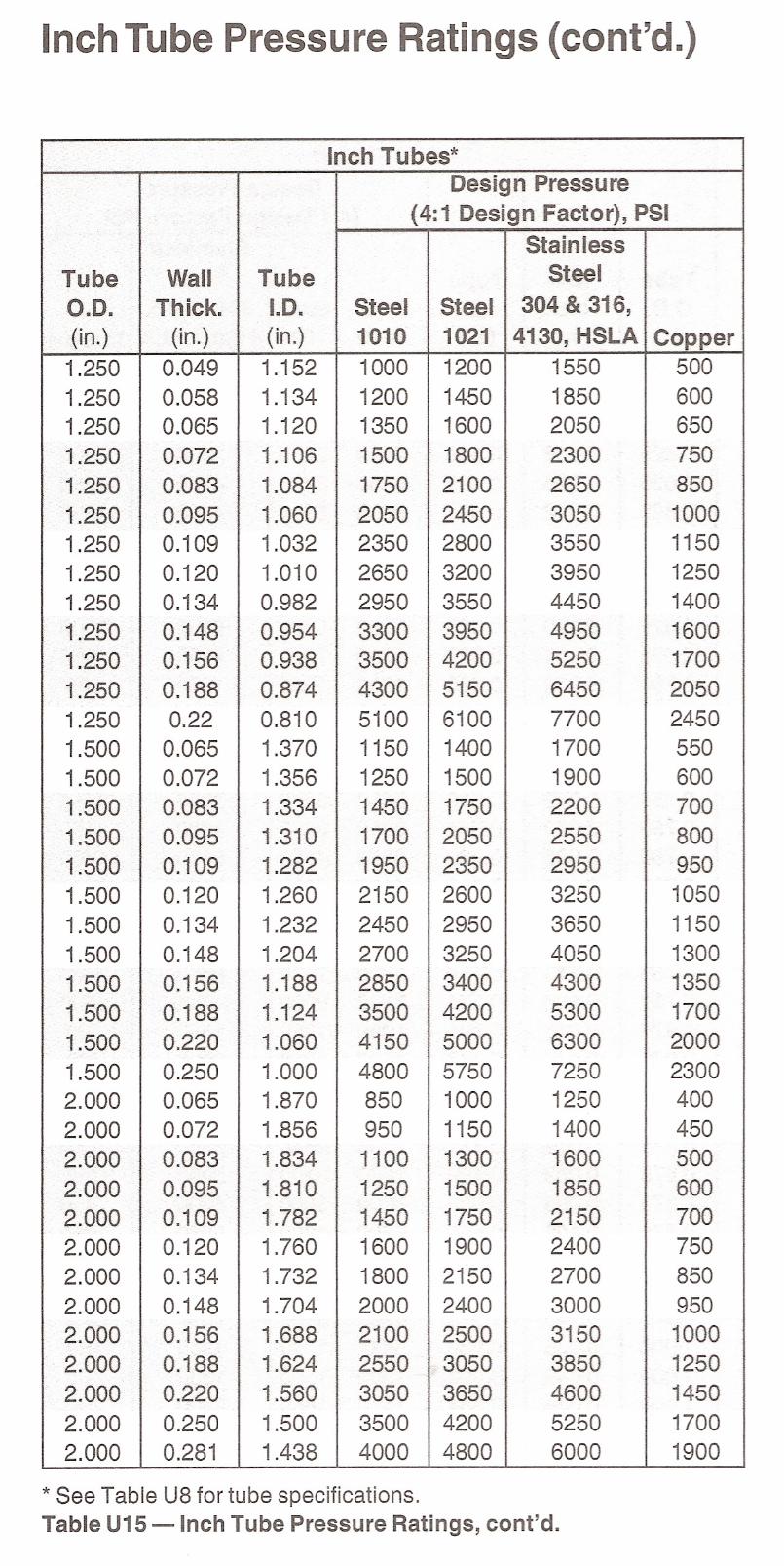
Inch Tube Pressure Ratings (cont'd.)
,.,.
..•....... ,...,.... Inch Tubes*
Design Pressure(4: 1 Design Factor), PSI'.'
Stain less
Tube
WallTube Steel
0.0.Thick ..I.D.SteelSteel304 & 316,
(in~).(in.)(in.)101010214130, HSLACopper
1.250
0.0491.152100012001550500
1.250
0.0581.134120014501850600
1.250
0.0651.120135016002050650
1.250
·0.0721.106150018002300750
'1:250 ..
0.0831.084175021002650850
1.250 .
0.0951.0602050245030501000
1.250
0.1091.0322350280035501150
1.250
0.1201.0102650320039501250
1.250
0.1340.9822950355044501400
1·.250
O.1480.9543300395049501600
,..·1.2500.1560.9383500420052501700
1.250
. 0.1880.8744300515064502050
1.250
0.220.8105100610077002450
1.500
0.0651.370115014001700550
1.500
0.0721.356125015001900600
·1.500
0.0831.334145017502200700-.. ···1.500 0.0951.310170020502550800
·1.500
0.1091.282195023502950950
1.500
0.1201.2602150260032501050
1.500
0.1341.2322450295036501150
1.500
0.1481.2042700325040501300
1.500
0.1561.1882850340043001350
1.500 .
O~1881.1243500420053001700
1.500
0.2201.0604150500063002000
1.500
0.2501.0004800575072502300
2.000
0.0651.87085010001250400
2.000
0.0721.85695011501400450
..2.000
·0.0831.834110013001600500
2;000
0.0951.810125015001850600
2.000
0.1091.782145017502150700
2.000
0.1201.760160019002400750
2.000
0.1341.732180021502700850
2.000
0.1481.704200024003000950
2.000 .
0.1561.6882100250031501000
·2.000
0.1881.6242550305038501250
...2.000
0.2201.5603050365046001450
2.000
0.2501.50035004200525017002.000
0.2811.4384000480060001900
* See Table U8 for tube specifications.Table U15 ~ Inch Tube Pressure Ratings, cont'd.
Recommended Flow Diameters - In Millimeters
Recommended Flow DiameterMaximum
in Millimeters
Flow Rate
PressureReturnSuctionLPM*
LinesLinesLines1
1.6702.6404.1802
2.3623.7345.9113
2.8934.5737.2404
3.3405.2808.3605
3.7345.9039.3476
4.0916.46710.2397
4.4186.98511.0598
4.7237.46711.8239
5.0107.92012.54010
5.2818.34813.21812
5.7859.14514.48014
6.2499.87815.64016
6.68010.56016.72018
7.08511.20117.73420
7.46811.80618.69422
7.83312.38319.60624
8.18112.93320.47826
8.51513.46121.31428
8.83713.97022.11830
9.14714.46022.89532
9.44714.93423.64634
9.73815.39424.37336
10.02015.84025.08038
10.29516.27425.76740
10.56216.69726.43745
11.20317.71028.04050
11.80918.66829.55755
12.38519.57931.00060
12.93620.44932.37865
13.46421.28433.70070
13.97222.08834.97275
14.46322.86336.20080
14.93723.61337.38785
15.39724.34038.53890
15.84325.04539.65595
16.27725.73240.742100
16.70026.40041.800110
17.51527.68943.840120
18.29428.92045.790130
19.04130.10147.659140
19.76031 .23749.458150
20.45332.33351.194160
21.12433.39452.873170
21.77434.42154.501180
22.40535.41956.081190
23.01936.39057.617200
23.61737.33559.114220
24.77039.15861.999240
25.87240.89964.756260
26.92842.56967.400280
27.94444.17669.945
Table U14 - Recommended Flow Diameters, inMillimeters
* LPM = Liters Per Minute
Recommended Flow DiameterMaximum
in Millimeters
Flow RatePressureReturnSuction
LPM*LinesLinesLines
30028.92545.72672.400
32029.87447.22674.774
34030.79348.67977.075
36031.68650.09079.310
38032.55451.46381 .483
40033.40052.80083.600
45035.42656.00388.671
50037.34259.03293.468
55039.16561.91398.030
60040.90664.667102.389
65042.57767.307106.570
70044.18469.848110.592
75045.73572.299114.474
80047.23574.670118.228

Metric Tube Pressure RatingsMetric Tu bes
Desian Pressure (Bar)Tube
WallTubeSteelStainless0.0.
Thick.1.0.Low-CarbonSteel
(mm)
(mm)(mm)St. 37-41.45714
0.53.0313256
4
0.752.5409366
4
1.02.0522465
5
0.83.5376301
5
1.03.0432386
6
0.754.5333256
6
1.04.0389330
6
1.53.0549465
6
2.02.0692585
6
2.251.5757639
8
1.06.0333256
8
1.55.0431366
8
2.04.0549465
8
2.53.0658556
10
1.08.0282209
10
1.57.0373301
10
2.06.0478386
10
2.55.0576465
10
3.04.0666539
12
1.010.0235177
12
1.59.0353256
12
2.08.0409330
12
2.57.0495400
12
3.06.0576465
12
3.55.0651527
14
1.012.0201153
14
1.511.0302223
14
2.010.0403289
14
2.59.0434351
14
3.08.0507410
14
3.57.0676465
14
4.06.0641518
15
1.013.0188143
15
1.512.0282209
15
2.011.0376271
15
2.510.0409330
15
3.09.0478386
16
1.014.0176135
16
1.513.0264197
16
2.012.0353256
16
2.511.0386312
16
3.010.0452366
18
1.016.0157121
18
1.515.0235177
18
2.014.0313230
18
2.513.0392281
18
3.012.0409330
20
1.517.0212160
20
2.016.0282209
20
2.515.0353256
20
3.014.0373301
20
3.513.0426345
20
4.012.0478386
22
1.020.0128100
22
1.519.0192146
22
2.018.0266192
22
2.517.0320235
22
3.016.0385277
25
2.021.0226170
25
2.520.0282209
25
3.019.0338247
Table U16 - Metric Tube Pressure Ratings
Metric TubesDesign Pressure (Bar)Tube
WallTubeSteelStainless0.0.
Thick.I.D.Low-CarbonSteel
(mm)(mm)(mm)St.37-41.4571
25
4.017.0394319
25
4.516.0437353
25
5.015.0478386
28
1.525.0151117
28
2.024.0201153
28
2.523.0252188
28
3.022.0302223
28
4.020.0403289
28
5.018.0434351
30
2.026.0188143
30
2.525.0235177
30
3.024.0282209
30
4.022.0376271
30
5.020.0409330
35
2.031.0161124
35
2.530.0201153
35
3.029.0242181
35
4.027.0322236
35
5.025.0403289
35
6.023.0419339
38
2.533.0186142
38
3.032.0223168
38
4.030.0297219
38
5.028.0371268
38
6.026.0390315
38
7.024.0446360
42
2.038.0134104
42
3.036.0201153
42
4.034.0269200
50
6.038.0338247
50
9.032.0437353
65
8.049.0347253
80
10.060.0353256
Related Documents


