IN DEGREE PROJECT MATERIALS SCIENCE AND ENGINEERING, SECOND CYCLE, 30 CREDITS , STOCKHOLM SWEDEN 2021 Determining the Influence of the Type of Shielding Gas during Additive Manufacturing of an Aluminum Alloy by Monitoring the Process Qualitatively and Analyzing Process Byproducts Quantitatively STEFANIE DESIREE KLEEMEYER KTH ROYAL INSTITUTE OF TECHNOLOGY SCHOOL OF INDUSTRIAL ENGINEERING AND MANAGEMENT

Welcome message from author
This document is posted to help you gain knowledge. Please leave a comment to let me know what you think about it! Share it to your friends and learn new things together.
Transcript
IN DEGREE PROJECT MATERIALS SCIENCE AND ENGINEERING,SECOND CYCLE, 30 CREDITS
, STOCKHOLM SWEDEN 2021
Determining the Influence of the Type of Shielding Gas during Additive Manufacturing of an Aluminum Alloy by Monitoring the Process Qualitatively and Analyzing Process Byproducts Quantitatively
STEFANIE DESIREE KLEEMEYER
KTH ROYAL INSTITUTE OF TECHNOLOGYSCHOOL OF INDUSTRIAL ENGINEERING AND MANAGEMENT
Determining the Influence of the Type of Shielding Gasduring Additive Manufacturing of an Aluminum Alloyby Monitoring the Process Qualitatively and Analyz-ing Process Byproducts Quantitatively
Stefanie Desiree Kleemeyer
Master in Materials ScienceDate: November 22, 2021Supervisor: Greta LindwallExaminer: Greta LindwallSchool of Industrial Engineering and ManagementHost company: Linde GmbHSwedish title: Bestämma påverkan av typen av skyddsgas under tillsatsstil-lverkning av en aluminiumlegering genom att övervaka processen kvalita-tivt och analysera process-vid-produkter kvantitativt
Abstract
This thesis analyzes the influence of process gases on the formation and the characteris-tics of process-by-products that emerge during additive manufacturing of an aluminumalloy belonging to the 2000 series. In order to address the influence, four pure gases,argon, nitrogen, helium, and carbon dioxide, were used as a shielding gas on the sameparameter sets. The interaction of the laser beam with the powder bed under eachshielding condition was recorded by a camera. The humidity, particle size distribution,and chemistry of the spatters produced after each job was analyzed. The chemistry ofsmall cylinders printed, was determined. The density of the produced cubic sampleswas determined following the Archimedes principle, as well as through the analysis ofthe cross-section. Lastly, the embedded and polished samples were etched, and thepenetration depth of the laser was determined. Under argon and nitrogen shielding,the process looked the same and the produced spatters show similar results. Underhelium shielding, less incandescent spatters were seen, and the particle size distributionis smaller than under argon or nitrogen. Carbon dioxide resulted in the highest numberof incandescent particles and a change of the color of the rays from red to yellow. Thechemical analysis shows that a slight increase of nitrogen in the spatters and the bulkmaterial can be seen under nitrogen shielding. Oxygen and hydrogen content was sim-ilar under argon, nitrogen, and helium shielding. Carbon dioxide shielding resulted inthe highest oxygen content in the spatter and the bulk material. The density is highestunder helium shielding, and lowest under carbon dioxide shielding. Under argon andnitrogen shielding, the density was similar. The study concluded that the choice of aprocess gas is not an arbitrary one but should be selected with care.
Keywords:additive manufacturing, PBF-LB/M, aluminum, shielding gas, argon, nitrogen, helium,carbon dioxide
i
Sammanfattning
Denna avhandling analyserar processgasernas påverkan på bildandet och egenskapernahos process-biprodukter som uppstår vid additiv tillverkning av en aluminiumlegeringsom tillhör 2000-serien. För att hantera inflytandet användes fyra rena gaser, argon,kväve, helium och koldioxid som skyddsgas på samma parameteruppsättningar. In-teraktionen mellan laserstrålen och pulverbädden under varje skärmningsförhållanderegistrerades av en kamera. Fuktigheten, partikelstorleksfördelningen och kemin hosstänkarna som producerades efter varje jobb analyserades. Kemien hos de små cylind-rarna som trycktes bestämdes. Densiteten hos de producerade kubikproven bestäm-des enligt Archimedes-principen, liksom genom analys av tvärsnittet. Slutligen etsadesde inbäddade och polerade proverna och laserns penetrationsdjup bestämdes. Underargon- och kväveavskärmning såg processen likadan ut och de producerade stänkarnavisar liknande resultat. Under heliumskärmning sågs mindre glödande stänk och par-tikelstorleksfördelningen är mindre än under argon eller kväve. Koldioxid resulterade idet högsta antalet glödande partiklar och en förändring av strålarnas färg från rött tillgult. Den kemiska analysen visar att en liten ökning av kväve i stänkarna och bulkma-terialet kan ses under kväveavskärmning. Syre- och väteinnehållet var liknande underargon-, kväve- och heliumskärmning. Koldioxidavskärmning resulterade i det högstasyreinnehållet i stänk och bulkmaterial. Densiteten är högst under heliumskärmningoch lägst under koldioxidskärmning. Under argon- och kväveavskärmning var densite-ten densamma. Studien drog slutsatsen att valet av en processgas inte är godtyckligtutan bör väljas med omsorg.
ii

Preface
Before you lies the thesis "Determining the Influence of the Type of Shielding Gas dur-ing Additive Manufacturing of an Aluminum Alloy by Monitoring the Process Qual-itatively and Analyzing Process Byproducts Quantitatively". It has been written tofulfill the requirements of the Materials Science and Engineering program at KungligaTekniska Högskolan (KTH).The research questions were formulated together with my supervisor Siegfried Baehr,whom I would like to thank for the supervision, guidance and support. Further, Iwould like to thank everyone at Linde, without you, I would not have been able toconduct my research and would not have been motivated to come to work everyday.I benefited from discussing ideas with my friends and would like to thank you, as well.Lastly, my parents deserve a particular note of thanks: you have always believed in meand made me the person I am now.
Thank you,Stefanie Kleemeyer
iii
CONTENTS
Contents
1 Introduction 11.1 Background . . . . . . . . . . . . . . . . . . . . . . . . . . . . . . . . . 11.2 Aim . . . . . . . . . . . . . . . . . . . . . . . . . . . . . . . . . . . . . 11.3 Delimitations . . . . . . . . . . . . . . . . . . . . . . . . . . . . . . . . 21.4 Research Question . . . . . . . . . . . . . . . . . . . . . . . . . . . . . 21.5 Sustainability Aspects . . . . . . . . . . . . . . . . . . . . . . . . . . . 2
2 Principles 42.1 Additive Manufacturing Processes . . . . . . . . . . . . . . . . . . . . . 42.2 Laser Powder Bed Fusion Process . . . . . . . . . . . . . . . . . . . . . 5
2.2.1 Process Parameters . . . . . . . . . . . . . . . . . . . . . . . . . 62.2.2 Typical Additive Manufacturing Defects . . . . . . . . . . . . . 7
2.3 Properties of Aluminum and the Influence of Alloying Elements . . . . 102.3.1 The Aluminum Alloying System . . . . . . . . . . . . . . . . . . 102.3.2 Difficulties when Processing Aluminum Alloys . . . . . . . . . . 11
3 State of Science and Technology 143.1 Process-by-Products in Laser Powder Bed Fusion . . . . . . . . . . . . 143.2 Influence of the Shielding Gas . . . . . . . . . . . . . . . . . . . . . . . 163.3 Processing of new High Strength Aluminum Alloys with PBF-LB/M . . 193.4 Conclusion . . . . . . . . . . . . . . . . . . . . . . . . . . . . . . . . . . 20
4 Methodology 214.1 Resources . . . . . . . . . . . . . . . . . . . . . . . . . . . . . . . . . . 21
4.1.1 Manufacturing Machine Aconity Mini . . . . . . . . . . . . . . . 214.1.2 Material: 2000 series . . . . . . . . . . . . . . . . . . . . . . . . 224.1.3 Gases . . . . . . . . . . . . . . . . . . . . . . . . . . . . . . . . 22
4.2 Analytical Techniques . . . . . . . . . . . . . . . . . . . . . . . . . . . 234.2.1 Powder Analysis . . . . . . . . . . . . . . . . . . . . . . . . . . 234.2.2 Process Observation . . . . . . . . . . . . . . . . . . . . . . . . 264.2.3 Metallographic Preparation and Analysis of Produced Cubes . . 26
5 Experimental Setup 295.1 Statistics . . . . . . . . . . . . . . . . . . . . . . . . . . . . . . . . . . . 29
5.1.1 Design of Experiments . . . . . . . . . . . . . . . . . . . . . . . 295.1.2 Statistical Evaluation . . . . . . . . . . . . . . . . . . . . . . . . 29
5.2 Experimental Work . . . . . . . . . . . . . . . . . . . . . . . . . . . . . 305.2.1 Parameter Study . . . . . . . . . . . . . . . . . . . . . . . . . . 315.2.2 Spatter and Powder Analysis . . . . . . . . . . . . . . . . . . . 32
iv
CONTENTS
6 Results 346.1 Process Observations . . . . . . . . . . . . . . . . . . . . . . . . . . . . 346.2 Powder Analysis . . . . . . . . . . . . . . . . . . . . . . . . . . . . . . 36
6.2.1 Particle Size Distribution . . . . . . . . . . . . . . . . . . . . . . 366.2.2 Shape Analysis of the Spatters . . . . . . . . . . . . . . . . . . . 386.2.3 Humidity Measurement . . . . . . . . . . . . . . . . . . . . . . . 416.2.4 Chemical Analysis . . . . . . . . . . . . . . . . . . . . . . . . . 42
6.3 Bulk Chemistry Analysis . . . . . . . . . . . . . . . . . . . . . . . . . . 456.4 Archimedes Method . . . . . . . . . . . . . . . . . . . . . . . . . . . . . 466.5 Relative Density . . . . . . . . . . . . . . . . . . . . . . . . . . . . . . . 486.6 Optical Analysis . . . . . . . . . . . . . . . . . . . . . . . . . . . . . . . 506.7 Penetration Depth . . . . . . . . . . . . . . . . . . . . . . . . . . . . . 616.8 Statistical Evaluation . . . . . . . . . . . . . . . . . . . . . . . . . . . . 62
7 Discussion 637.1 Influence of the Process Gases on the Formation of Process-by-Products
- RQ1 . . . . . . . . . . . . . . . . . . . . . . . . . . . . . . . . . . . . 637.2 Influence of the Process Gases on the Characteristics of Process-by-
Products - RQ2 . . . . . . . . . . . . . . . . . . . . . . . . . . . . . . . 657.3 Influence of the Shielding Gas on the Finished Part - RQ3 . . . . . . . 66
7.3.1 Defect Formation through Insufficient Removal ofProcess-by-Products . . . . . . . . . . . . . . . . . . . . . . . . 66
7.3.2 Change in Chemistry of the Printed Component . . . . . . . . . 687.3.3 Likelihood of Oxidation of the Surface of the Liquid Melt . . . . 687.3.4 Implication of the Presence of an Oxide Layer . . . . . . . . . . 69
8 Conclusions and Future Work 71
9 Acknowledgments 74
10 References 75
v
1 INTRODUCTION
1 Introduction
1.1 Background
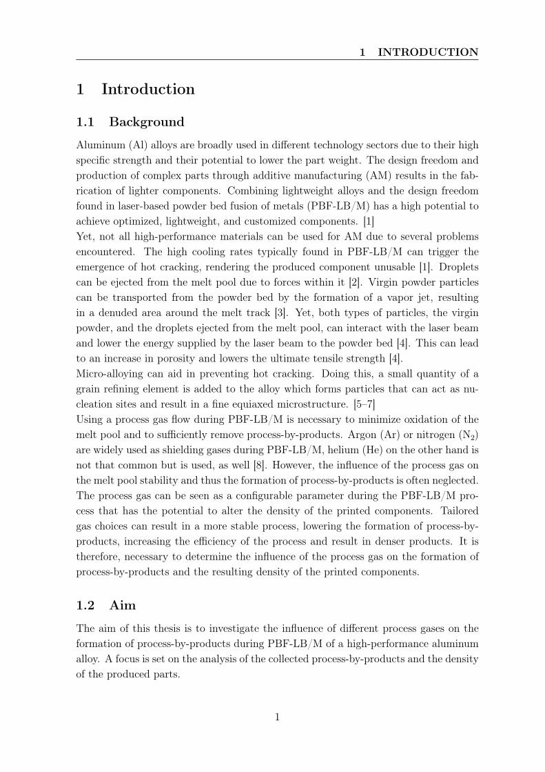
Aluminum (Al) alloys are broadly used in different technology sectors due to their highspecific strength and their potential to lower the part weight. The design freedom andproduction of complex parts through additive manufacturing (AM) results in the fab-rication of lighter components. Combining lightweight alloys and the design freedomfound in laser-based powder bed fusion of metals (PBF-LB/M) has a high potential toachieve optimized, lightweight, and customized components. [1]Yet, not all high-performance materials can be used for AM due to several problemsencountered. The high cooling rates typically found in PBF-LB/M can trigger theemergence of hot cracking, rendering the produced component unusable [1]. Dropletscan be ejected from the melt pool due to forces within it [2]. Virgin powder particlescan be transported from the powder bed by the formation of a vapor jet, resultingin a denuded area around the melt track [3]. Yet, both types of particles, the virginpowder, and the droplets ejected from the melt pool, can interact with the laser beamand lower the energy supplied by the laser beam to the powder bed [4]. This can leadto an increase in porosity and lowers the ultimate tensile strength [4].Micro-alloying can aid in preventing hot cracking. Doing this, a small quantity of agrain refining element is added to the alloy which forms particles that can act as nu-cleation sites and result in a fine equiaxed microstructure. [5–7]Using a process gas flow during PBF-LB/M is necessary to minimize oxidation of themelt pool and to sufficiently remove process-by-products. Argon (Ar) or nitrogen (N2)are widely used as shielding gases during PBF-LB/M, helium (He) on the other hand isnot that common but is used, as well [8]. However, the influence of the process gas onthe melt pool stability and thus the formation of process-by-products is often neglected.The process gas can be seen as a configurable parameter during the PBF-LB/M pro-cess that has the potential to alter the density of the printed components. Tailoredgas choices can result in a more stable process, lowering the formation of process-by-products, increasing the efficiency of the process and result in denser products. It istherefore, necessary to determine the influence of the process gas on the formation ofprocess-by-products and the resulting density of the printed components.
1.2 Aim
The aim of this thesis is to investigate the influence of different process gases on theformation of process-by-products during PBF-LB/M of a high-performance aluminumalloy. A focus is set on the analysis of the collected process-by-products and the densityof the produced parts.
1
1 INTRODUCTION
1.3 Delimitations
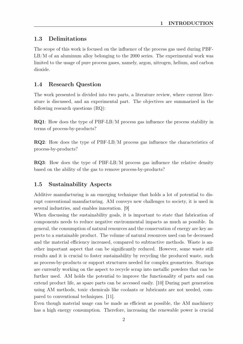
The scope of this work is focused on the influence of the process gas used during PBF-LB/M of an aluminum alloy belonging to the 2000 series. The experimental work waslimited to the usage of pure process gases, namely, argon, nitrogen, helium, and carbondioxide.
1.4 Research Question
The work presented is divided into two parts, a literature review, where current liter-ature is discussed, and an experimental part. The objectives are summarized in thefollowing research questions (RQ):
RQ1: How does the type of PBF-LB/M process gas influence the process stability interms of process-by-products?
RQ2: How does the type of PBF-LB/M process gas influence the characteristics ofprocess-by-products?
RQ3: How does the type of PBF-LB/M process gas influence the relative densitybased on the ability of the gas to remove process-by-products?
1.5 Sustainability Aspects
Additive manufacturing is an emerging technique that holds a lot of potential to dis-rupt conventional manufacturing. AM conveys new challenges to society, it is used inseveral industries, and enables innovation. [9]When discussing the sustainability goals, it is important to state that fabrication ofcomponents needs to reduce negative environmental impacts as much as possible. Ingeneral, the consumption of natural resources and the conservation of energy are key as-pects to a sustainable product. The volume of natural resources used can be decreasedand the material efficiency increased, compared to subtractive methods. Waste is an-other important aspect that can be significantly reduced. However, some waste stillresults and it is crucial to foster sustainability by recycling the produced waste, suchas process-by-products or support structures needed for complex geometries. Startupsare currently working on the aspect to recycle scrap into metallic powders that can befurther used. AM holds the potential to improve the functionality of parts and canextend product life, as spare parts can be accessed easily. [10] During part generationusing AM methods, toxic chemicals like coolants or lubricants are not needed, com-pared to conventional techniques. [11].Even though material usage can be made as efficient as possible, the AM machineryhas a high energy consumption. Therefore, increasing the renewable power is crucial
2
1 INTRODUCTION
to help fight climate change. This is the biggest burden, as a fully renewable electrifiedindustrial environment is not yet achieved, and will take some more years to be inplace. The AM process needs to be optimized to mitigate the production of defectiveparts, as those not only result in scrap, but also in energy being wasted. Usage of thecorrect shielding gas for each material can make the process more reliable and repeat-able, which can reduce defective parts. [10]Not only are economical and environmental aspects of importance, but social sustain-ability should be mentioned as well. The link to a more socially sustainable futurethrough AM is not as obvious as the previously mentioned points, however, it is there.AM has the potential to improve education, as products to be shown in classes atschool and university can be made more easily. Through customization, protheses canbe tailor-made and improve the quality of life. [9] Yet, working with metallic powdersintroduces a new risk that can easily be neglected if safety standards are low. At Linde,the powder is stored in a separate locked room, extensive personal protective equip-ment has to be worn when powder is handled. Powder contaminated waste is collectedin designated bins and is specially disposed of. Even though these aspects should bestandard safety precautions, those standards are not always the case.Lastly the applicable sustainable development goals with regard to the AM technol-ogy, as defined by the United Nations [12], are shown. This technology has a potentialto impact goals 9 and 12. Goal 9 wishes to achieve sustainable industrialization andinnovation. Additive manufacturing promotes the establishment of startups that man-ufacture individual and customized parts, being independent of large manufacturingplants [13]. Material efficiency is increased and raw material costs reduced, while in-creasing the functionality of the part. Goal 12 promotes sustainable consumption andproduction. Significant amounts of waste can be reduced compared to subtractive man-ufacturing. By correctly placing the parts on the build plate supports can be reduced,and less scrap material is generated.
3
2 PRINCIPLES
2 Principles
2.1 Additive Manufacturing Processes
The standard for additive manufacturing ISO-ASTM 52900 [14] defines AM as a "pro-cess of joining materials to make parts from 3D model data, usually layer upon layer, asopposed to subtractive manufacturing and formative manufacturing methodologies".The term additive manufacturing is a collection of different manufacturing processesthat all have in common that a component is build by the addition of material. Conven-tional manufacturing processes usually rely on the removal of material, i.e., subtractingmaterial to produce a part. What makes additive manufacturing processes unique isthat there is no need for design specific tooling. [13, 15, 16]The different additive manufacturing techniques can further be classified into sevencategories [14]:
• vat photopolymerization
• material jetting
• powder bed fusion
• direct energy deposition
• material extrusion
• binder jetting
• sheet lamination
Additive manufacturing technologies are primarily used for parts with complex shapesand difficult geometries or when customization is wanted. Furthermore, AM can removeassembly steps and thus lower production costs. [13]The additive manufacturing processes starts with a computer aided design (CAD)model. This model is then converted into standard triangle language (STL) where themodel is resembled by many small interconnected triangles. Finally, the model has tobe sliced into horizontal layers. The distance between the slices represents the layerthickness. Lastly, a G-code is generated, which comprises the information required bythe machine, to convert the digital model into a physical one. The part is built fromthe bottom up, and successive layers are added. The process is finished when the lastlayer is manufactured. [15] Additive manufacturing processes can be used on variousmaterials, including metals, polymers, ceramics, composites, as well as functionallygraded material.
4
2 PRINCIPLES
2.2 Laser Powder Bed Fusion Process
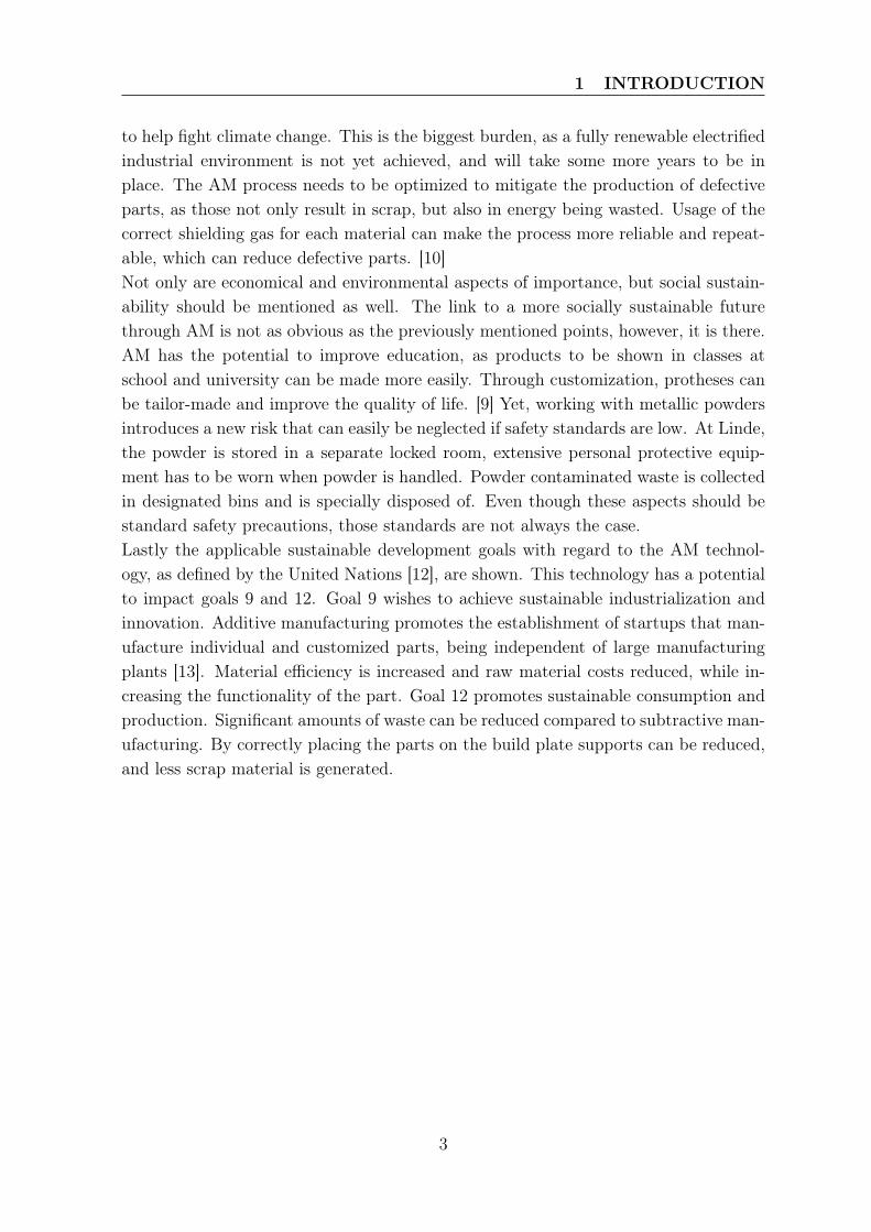
One example for a an additive manufacturing process is the laser powder bed fusiontechnique. Here, a bed of powder is created, which is selectively fused by focusedenergy, i.e., a laser beam to generate a part [13, 15, 17]. To be able to achieve this,the machine is made up out of different components, that interact to create an item.The following components can be found in most PBF-LB/M systems, as illustrated inFigure 1. The optical system which is comprised of a laser and a scanner system isused to maneuver the laser to the corresponding position as set in the G-code. Thepowder bed is made by spreading powder from the reservoir by the recoater on to thebuild plate. The plate is needed to give the part mechanical and thermal support. Anyexcess powder is collected in the overflow bin. [17]
Figure 1: Schematic drawing of the components of a LPBF-M system. Own represan-tation based on [18].
To produce a component, a thin layer of powder is spread manually by the recoater.All consecutive layers are applied automatically, the layer thickness represents theslice thickness of the digital CAD model. A laser then selectively melts the powderfollowing a pattern corresponding to the current slice of the CAD model. The nextlayer of powder is added by the recoater and is selectively melted. It is important thatduring each melting step the previously fused layer is partially re-melted to achievegood adherence of the component. This process is repeated over several layers, untilthe last slice is scanned and the part is finished. [13, 15, 17] Once the part is completed,all of the loose powder on the build plate is collected in the overflow container. It canbe sieved and reused. Sieving is important to remove bigger particles, e.g., spatters oragglomerates. The whole build process is carried out in a sealed build chamber and is
5
2 PRINCIPLES
purged with a process gas to create a specified atmosphere.Certain steps are needed to produce a part. There are the machine set-up, whichis followed by the operation of the machine. Once the part is finished the excesspowder has to be removed and recovered. Finally, the substrate plate, where the finalcomponent is fused onto can be removed. [17]
2.2.1 Process Parameters
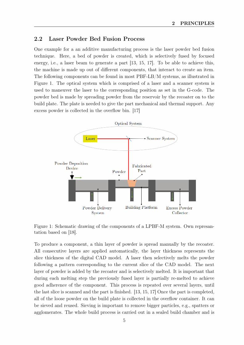
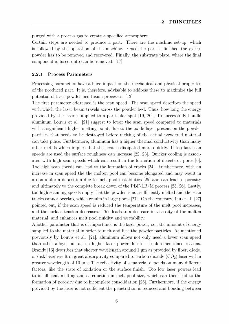
Processing parameters have a huge impact on the mechanical and physical propertiesof the produced part. It is, therefore, advisable to address these to maximize the fullpotential of laser powder bed fusion processes. [13]The first parameter addressed is the scan speed. The scan speed describes the speedwith which the laser beam travels across the powder bed. Thus, how long the energyprovided by the laser is applied to a particular spot [19, 20]. To successfully handlealuminum Louvis et al. [21] suggest to lower the scan speed compared to materialswith a significant higher melting point, due to the oxide layer present on the powderparticles that needs to be destroyed before melting of the actual powdered materialcan take place. Furthermore, aluminum has a higher thermal conductivity than manyother metals which implies that the heat is dissipated more quickly. If too fast scanspeeds are used the surface roughness can increase [22, 23]. Quicker cooling is associ-ated with high scan speeds which can result in the formation of defects or pores [6].Too high scan speeds can lead to the formation of cracks [24]. Furthermore, with anincrease in scan speed the the molten pool can become elongated and may result ina non-uniform deposition due to melt pool instabilities [25] and can lead to porosityand ultimately to the complete break down of the PBF-LB/M process [23, 26]. Lastly,too high scanning speeds imply that the powder is not sufficiently melted and the scantracks cannot overlap, which results in large pores [27]. On the contrary, Liu et al. [27]pointed out, if the scan speed is reduced the temperature of the melt pool increases,and the surface tension decreases. This leads to a decrease in viscosity of the moltenmaterial, and enhances melt pool fluidity and wettability.Another parameter that is of importance is the laser power, i.e., the amount of energysupplied to the material in order to melt and fuse the powder particles. As mentionedpreviously by Louvis et al. [21], aluminum alloys not only need a lower scan speedthan other alloys, but also a higher laser power due to the aforementioned reasons.Brandt [16] describes that shorter wavelength around 1 µm as provided by fiber, diode,or disk laser result in great absorptivity compared to carbon dioxide (CO2) laser with agreater wavelength of 10 µm. The reflectivity of a material depends on many differentfactors, like the state of oxidation or the surface finish. Too low laser powers leadto insufficient melting and a reduction in melt pool size, which can then lead to theformation of porosity due to incomplete consolidation [26]. Furthermore, if the energyprovided by the laser is not sufficient the penetration is reduced and bonding between
6
2 PRINCIPLES
the layers is limited [26]. Too high laser power results in keyhole welding. Due to thecollapse of the keyhole, voids can be left inside the material after solidification [28].Oliveira et al. [29] describe the hatch distance as the lateral displacement of the laserbeam between two adjacent tracks. It cannot be determined theoretically only throughexperiments. The hatch spacing is crucial for intra-layer bonding, affecting the relativedensity of the component [27] An increase in hatch spacing, i.e., the scan tracks arefurther apart, results in a lack of overlap, and thus incomplete consolidation [27, 29].Hence, the hatch spacing should be selected carefully to ensure that the deposited trackis fully joined to its neighboring track [29].Brandt [16] states that typical layer thicknesses used during PBF-LB/M is 30 - 100 µm.If the layer thickness is too high, complete melting of the powder layer and partialremelting of the underlying solidified layers can not be achieved, resulting in the for-mation of defects. On the other hand, if the layer thickness is too small, spreading ofhomogeneous layers is not longer possible, resulting in surface roughness. [30].As can be seen, the most fundamental parameters, scan speed, laser power, hatch dis-tance, and layer thickness, all influence the density of the printed component [31]. Theirrelationship is described by the volumetric energy density (VED) and is determined bythe following equation [30]:
VED =Pvht
(1)
Where P is the laser power in W, v is the scan speed in mm/s, h is the hatch distancein mm, and t is the layer thickness in mm. The unit of the volumetric energy densityis J/mm3. Increasing the VED, the amount of liquid phase is greater and solidificationtime is longer, resulting in better wetting, and lower porosity [31]. However, if theVED is too high, porosity increases and the accumulation of stress and distortion ofthe components is a direct result [30].Lastly, the temperature encountered during additive manufacturing also highly dependson the process parameters. Li et al. [32] simulated the temperature during PBF-LB/Mof an AlSi10Mg alloy, and found a temperature range from 937 °C to 1817 °C for thelaser power ranging from 150 W to 300 W and the scan speeds between 100 mm/s and400 mm/s.
2.2.2 Typical Additive Manufacturing Defects
The PBF-LB/M process is, as any other process, not free of flaws and imperfections.According to Brandt [16] lack of fusion, porosity and cracks are often generated inadditively manufactured material. The mechanical properties of the manufacturedpart can be reduced, as fatigue strength, elongation to failure and tensile strength allvary with the parameters chosen and hence the form of pores they might introduceinto the material [33]. Furthermore, not only does the bulk density, i.e., the numberof pores, play a role on mechanical properties but pore size and its morphology is of
7
2 PRINCIPLES
crucial importance [33] as they can act as stress risers [16]. Gong et al. [34] point outthat the three most commonly formed defects can be classified into keyhole porosity,metallurgical or gas pores, and lack of fusion porosity.Keyhole mode porosity is formed when the energy density is high, i.e., high laser powerand / or slow scan speed. A vapor depression is formed at the bottom of the melt poolwith high liquid flow velocities. The keyhole can become unstable and the depressioncollapses as the melt pool propagates forward and voids that consist of entrapped vaporare formed at the bottom. They are large and rounded, but not necessarily spherical.[24, 28, 35] The shape and size of the keyhole influences the size of the keyhole porosity[25].On the contrary if the energy density is too low, i.e., a low laser power is used or a highscan speed the powdered particles are insufficiently melted and fusion of the materialis inhibited which results in irregularly shaped pores with sharper edges and varyingsizes [35]. Entrapped unmelted powder particles can be found inside the voids [16].Lack of fusion pores are larger than metallurgical pores or gas pores [25].Gas pores / metallurgical pores are spherical pores with a diameter around or smallerthan 20 µm [35]. Gas pores can be formed due to the entrapment of inert shieldinggases that are insoluble in the melt. Pores that are formed in the liquid metal remainin the solidified melt pool, unless they can float up and escape from the melt pool [25].Due to Marangoni convection in the melt pool, gas bubbles that are inside the meltpool can be transported to different locations, e.g., to the bottom of the melt pool orto the surface [36, 37]. Furthermore, the state of the powder particles can influence theporosity as well. Voids inside the powder particles can lead to microscopical porosity[25]. Humidity (water - H2O) present on the surface of the powder particles due toproduction, storage, or handling can be decomposed during the melting process andreact with aluminum and forms aluminum oxide (Al2O3) and hydrogen (H2) by thefollowing equation [36, 38]:
3H2O + 2Al→ Al2O3 + 3H2 (2)
The now present hydrogen can be absorbed (Hab) by the melt pool:
H2→ 2Hab (3)
If the hydrogen content in the melt is higher than the solubility limit of liquid aluminum,nucleation and growth of hydrogen pores is initiated. Solubility of hydrogen in the meltis approximately 10 times higher than in the solidified material, leading to the formationof gas pores. [38]Further on, the formation of pores due to instabilities in the melt flow at high scanspeeds should be mentioned. Instabilities arise due to Marangoni convection and recoilpressures associated with the vaporization of elements from the melt pool [16, 39].
8
2 PRINCIPLES
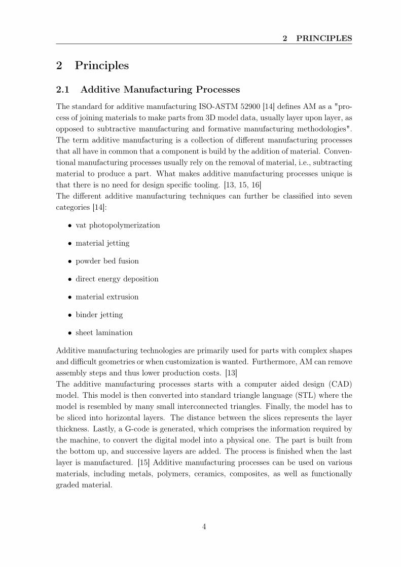
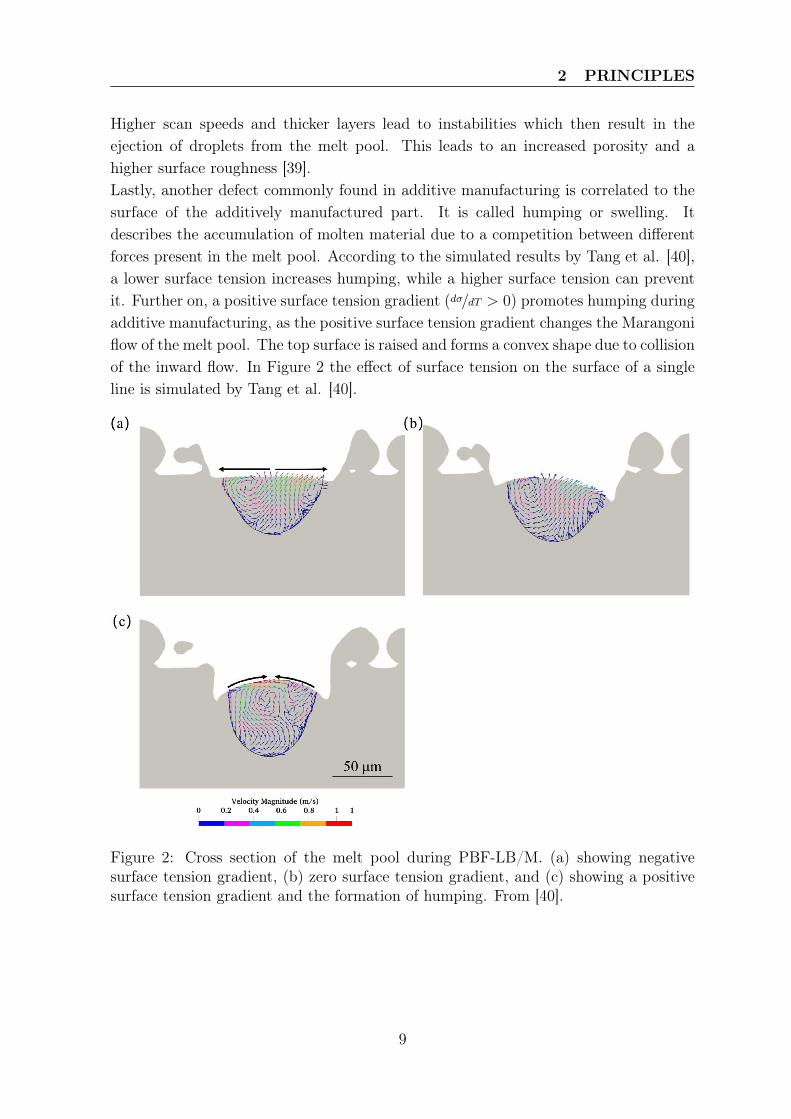
Higher scan speeds and thicker layers lead to instabilities which then result in theejection of droplets from the melt pool. This leads to an increased porosity and ahigher surface roughness [39].Lastly, another defect commonly found in additive manufacturing is correlated to thesurface of the additively manufactured part. It is called humping or swelling. Itdescribes the accumulation of molten material due to a competition between differentforces present in the melt pool. According to the simulated results by Tang et al. [40],a lower surface tension increases humping, while a higher surface tension can preventit. Further on, a positive surface tension gradient (dσ/dT > 0) promotes humping duringadditive manufacturing, as the positive surface tension gradient changes the Marangoniflow of the melt pool. The top surface is raised and forms a convex shape due to collisionof the inward flow. In Figure 2 the effect of surface tension on the surface of a singleline is simulated by Tang et al. [40].
Figure 2: Cross section of the melt pool during PBF-LB/M. (a) showing negativesurface tension gradient, (b) zero surface tension gradient, and (c) showing a positivesurface tension gradient and the formation of humping. From [40].
9
2 PRINCIPLES
2.3 Properties of Aluminum and the Influence of Alloying Ele-ments
2.3.1 The Aluminum Alloying System
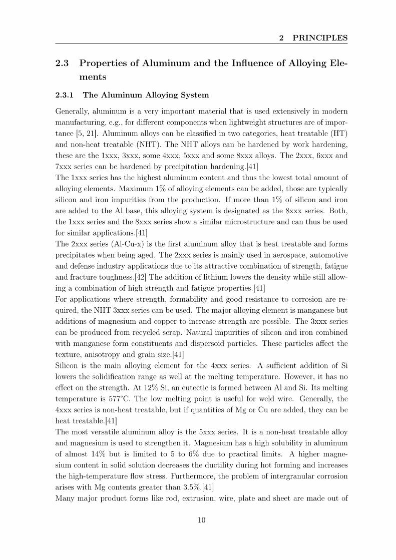
Generally, aluminum is a very important material that is used extensively in modernmanufacturing, e.g., for different components when lightweight structures are of impor-tance [5, 21]. Aluminum alloys can be classified in two categories, heat treatable (HT)and non-heat treatable (NHT). The NHT alloys can be hardened by work hardening,these are the 1xxx, 3xxx, some 4xxx, 5xxx and some 8xxx alloys. The 2xxx, 6xxx and7xxx series can be hardened by precipitation hardening.[41]The 1xxx series has the highest aluminum content and thus the lowest total amount ofalloying elements. Maximum 1% of alloying elements can be added, those are typicallysilicon and iron impurities from the production. If more than 1% of silicon and ironare added to the Al base, this alloying system is designated as the 8xxx series. Both,the 1xxx series and the 8xxx series show a similar microstructure and can thus be usedfor similar applications.[41]The 2xxx series (Al-Cu-x) is the first aluminum alloy that is heat treatable and formsprecipitates when being aged. The 2xxx series is mainly used in aerospace, automotiveand defense industry applications due to its attractive combination of strength, fatigueand fracture toughness.[42] The addition of lithium lowers the density while still allow-ing a combination of high strength and fatigue properties.[41]For applications where strength, formability and good resistance to corrosion are re-quired, the NHT 3xxx series can be used. The major alloying element is manganese butadditions of magnesium and copper to increase strength are possible. The 3xxx seriescan be produced from recycled scrap. Natural impurities of silicon and iron combinedwith manganese form constituents and dispersoid particles. These particles affect thetexture, anisotropy and grain size.[41]Silicon is the main alloying element for the 4xxx series. A sufficient addition of Silowers the solidification range as well at the melting temperature. However, it has noeffect on the strength. At 12% Si, an eutectic is formed between Al and Si. Its meltingtemperature is 577°C. The low melting point is useful for weld wire. Generally, the4xxx series is non-heat treatable, but if quantities of Mg or Cu are added, they can beheat treatable.[41]The most versatile aluminum alloy is the 5xxx series. It is a non-heat treatable alloyand magnesium is used to strengthen it. Magnesium has a high solubility in aluminumof almost 14% but is limited to 5 to 6% due to practical limits. A higher magne-sium content in solid solution decreases the ductility during hot forming and increasesthe high-temperature flow stress. Furthermore, the problem of intergranular corrosionarises with Mg contents greater than 3.5%.[41]Many major product forms like rod, extrusion, wire, plate and sheet are made out of
10
2 PRINCIPLES
the heat treatable 6xxx series. They can easily be made by cold or hot deformation.Due to a wide range of alloy compositions different strength levels can be achieved.The 6xxx alloys (Al-Mg-Si) are superior in welding, joining and finishing compared tothe high strength 2xxx and 7xxx series.[41]The 7xxx alloy families (Al-Zn-Mg-Cu) are capable of reaching high strength levels,greater than 600MPa, through a heat treatment. The Al-Zn-Mg-Cu alloys are mainlyused in airplanes where the superior strength/weight ratio can be exploited.[41]
2.3.2 Difficulties when Processing Aluminum Alloys
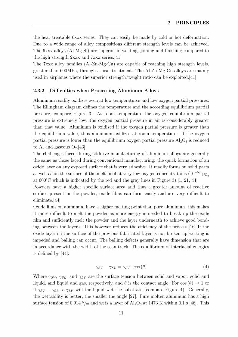
Aluminum readily oxidizes even at low temperatures and low oxygen partial pressures.The Ellingham diagram defines the temperature and the according equilibrium partialpressure, compare Figure 3. At room temperature the oxygen equilibrium partialpressure is extremely low, the oxygen partial pressure in air is considerably greaterthan that value. Aluminum is oxidized if the oxygen partial pressure is greater thanthe equilibrium value, thus aluminum oxidizes at room temperature. If the oxygenpartial pressure is lower than the equilibrium oxygen partial pressure Al2O3 is reducedto Al and gaseous O2.[43]The challenges faced during additive manufacturing of aluminum alloys are generallythe same as those faced during conventional manufacturing: the quick formation of anoxide layer on any exposed surface that is very adhesive. It readily forms on solid partsas well as on the surface of the melt pool at very low oxygen concentrations (10−52 pO2
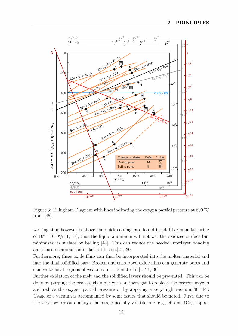
at 600°C which is indicated by the red and the gray lines in Figure 3).[1, 21, 44]Powders have a higher specific surface area and thus a greater amount of reactivesurface present in the powder, oxide films can form easily and are very difficult toeliminate.[44]Oxide films on aluminum have a higher melting point than pure aluminum, this makesit more difficult to melt the powder as more energy is needed to break up the oxidefilm and sufficiently melt the powder and the layer underneath to achieve good bond-ing between the layers. This however reduces the efficiency of the process.[16] If theoxide layer on the surface of the previous fabricated layer is not broken up wetting isimpeded and balling can occur. The balling defects generally have dimension that arein accordance with the width of the scan track. The equilibrium of interfacial energiesis defined by [44]:
γSV − γSL = γLV · cos (θ) (4)
Where γSV , γSL, and γLV are the surface tension between solid and vapor, solid andliquid, and liquid and gas, respectively, and θ is the contact angle. For cos (θ)→ 1 orif γSV − γSL > γLV will the liquid wet the substrate (compare Figure 4). Generally,the wettability is better, the smaller the angle [27]. Pure molten aluminum has a highsurface tension of 0.914 N/m and wets a layer of Al2O3 at 1473 K within 0.1 s [46]. This
11
2 PRINCIPLES
Figure 3: Ellingham Diagram with lines indicating the oxygen partial pressure at 600 °Cfrom [45].
wetting time however is above the quick cooling rate found in additive manufacturingof 105 - 106 K/s [1, 47], thus the liquid aluminum will not wet the oxidized surface butminimizes its surface by balling [44]. This can reduce the needed interlayer bondingand cause delamination or lack of fusion.[21, 30]Furthermore, these oxide films can then be incorporated into the molten material andinto the final solidified part. Broken and entrapped oxide films can generate pores andcan evoke local regions of weakness in the material.[1, 21, 30]Further oxidation of the melt and the solidified layers should be prevented. This can bedone by purging the process chamber with an inert gas to replace the present oxygenand reduce the oxygen partial pressure or by applying a very high vacuum.[30, 44].Usage of a vacuum is accompanied by some issues that should be noted. First, due tothe very low pressure many elements, especially volatile ones e.g., chrome (Cr), copper
12
2 PRINCIPLES
Figure 4: Schematic representation of wetting and non-wetting systems with the in-volved interfacial energies. Own representation, based on [44].
(Cu), magnesium (Mg), manganese (Mn), can vaporize and deplete the matrix andthus change the alloy composition. Second, the mean free path, λ, i.e, the distance aparticle can travel before colliding with other particles and thus changing its directionor energy, which is defined by [44], increases for lower pressures:
λ =k · T√
2 · p · σ2(5)
Where k is the Boltzmann’s constant, T is the absolute temperature, p is the pressureand σ is the molecular diameter. For σ = 5 Å, T = 298 K and p = 1.013 · 10-4 Pathe mean free path is λ = 35.9 m. The vertical distance between the powder bed andthe laser coupling glass is typically around 0.5 m. The calculated path length at ahigh vacuum implies that the volatiles can move unimpeded and condensate on thechamber walls and on the laser window. This might lead to scattering of the laserlight and poor mechanical properties of the manufactured parts. The mean free pathfor the same conditions except a pressure of p=1.013 · 105 Pa is λ = 3.59 · 10-9 m.Hence, no volatile elements will condensate on the glass or the walls. Therefore, a highpurity inert gas processing atmosphere is more advisable compared to a high vacuumto mitigate the problems connected with oxidation of the surface. Unfortunately, ahigh purity processing atmosphere is difficult to achieve as many factors have to beconsidered. [44] These are the purity of the gas itself, leakages in the system, diffusionthrough the pipes connecting the gas and the machine, and surface contamination ofthe powder particles [10]. Thus the formation of an oxide layer on the melt pool canonly be avoided to a certain degree.
13
3 STATE OF SCIENCE AND TECHNOLOGY
3 State of Science and Technology
3.1 Process-by-Products in Laser Powder Bed Fusion
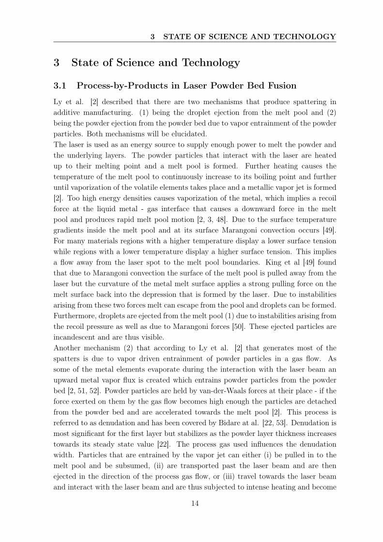
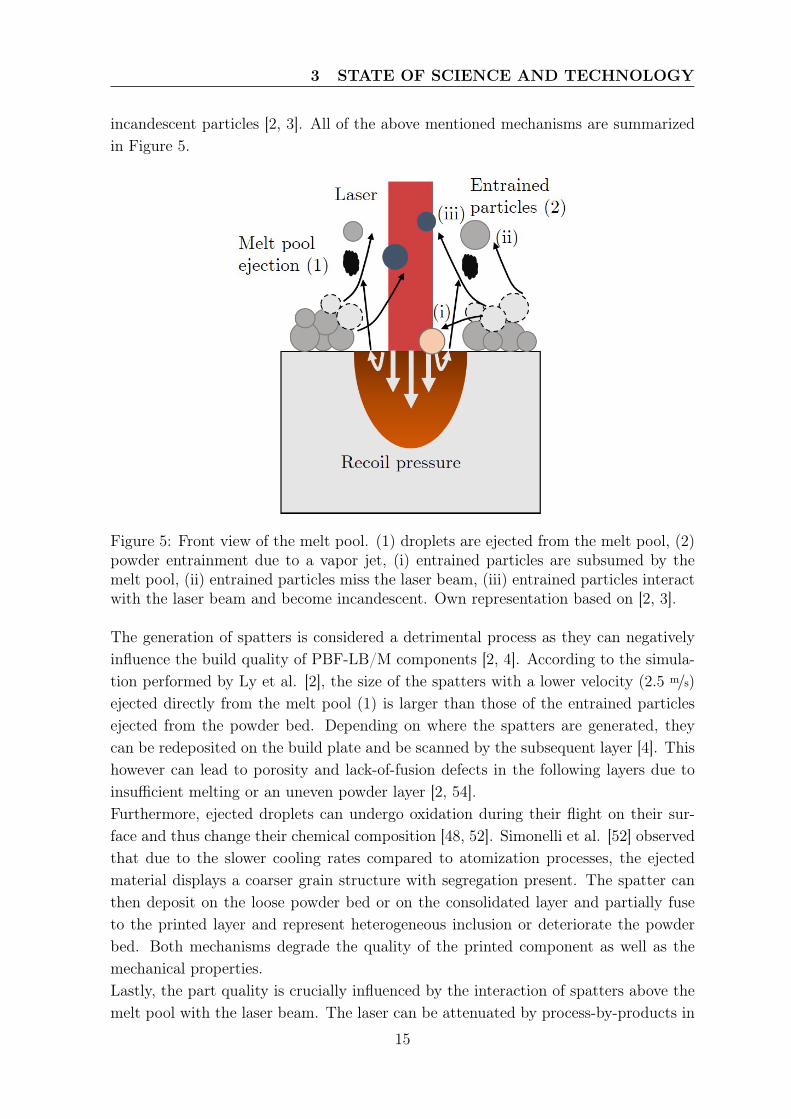
Ly et al. [2] described that there are two mechanisms that produce spattering inadditive manufacturing. (1) being the droplet ejection from the melt pool and (2)being the powder ejection from the powder bed due to vapor entrainment of the powderparticles. Both mechanisms will be elucidated.The laser is used as an energy source to supply enough power to melt the powder andthe underlying layers. The powder particles that interact with the laser are heatedup to their melting point and a melt pool is formed. Further heating causes thetemperature of the melt pool to continuously increase to its boiling point and furtheruntil vaporization of the volatile elements takes place and a metallic vapor jet is formed[2]. Too high energy densities causes vaporization of the metal, which implies a recoilforce at the liquid metal - gas interface that causes a downward force in the meltpool and produces rapid melt pool motion [2, 3, 48]. Due to the surface temperaturegradients inside the melt pool and at its surface Marangoni convection occurs [49].For many materials regions with a higher temperature display a lower surface tensionwhile regions with a lower temperature display a higher surface tension. This impliesa flow away from the laser spot to the melt pool boundaries. King et al [49] foundthat due to Marangoni convection the surface of the melt pool is pulled away from thelaser but the curvature of the metal melt surface applies a strong pulling force on themelt surface back into the depression that is formed by the laser. Due to instabilitiesarising from these two forces melt can escape from the pool and droplets can be formed.Furthermore, droplets are ejected from the melt pool (1) due to instabilities arising fromthe recoil pressure as well as due to Marangoni forces [50]. These ejected particles areincandescent and are thus visible.Another mechanism (2) that according to Ly et al. [2] that generates most of thespatters is due to vapor driven entrainment of powder particles in a gas flow. Assome of the metal elements evaporate during the interaction with the laser beam anupward metal vapor flux is created which entrains powder particles from the powderbed [2, 51, 52]. Powder particles are held by van-der-Waals forces at their place - if theforce exerted on them by the gas flow becomes high enough the particles are detachedfrom the powder bed and are accelerated towards the melt pool [2]. This process isreferred to as denudation and has been covered by Bidare at al. [22, 53]. Denudation ismost significant for the first layer but stabilizes as the powder layer thickness increasestowards its steady state value [22]. The process gas used influences the denudationwidth. Particles that are entrained by the vapor jet can either (i) be pulled in to themelt pool and be subsumed, (ii) are transported past the laser beam and are thenejected in the direction of the process gas flow, or (iii) travel towards the laser beamand interact with the laser beam and are thus subjected to intense heating and become
14
3 STATE OF SCIENCE AND TECHNOLOGY
incandescent particles [2, 3]. All of the above mentioned mechanisms are summarizedin Figure 5.
Figure 5: Front view of the melt pool. (1) droplets are ejected from the melt pool, (2)powder entrainment due to a vapor jet, (i) entrained particles are subsumed by themelt pool, (ii) entrained particles miss the laser beam, (iii) entrained particles interactwith the laser beam and become incandescent. Own representation based on [2, 3].
The generation of spatters is considered a detrimental process as they can negativelyinfluence the build quality of PBF-LB/M components [2, 4]. According to the simula-tion performed by Ly et al. [2], the size of the spatters with a lower velocity (2.5 m/s)ejected directly from the melt pool (1) is larger than those of the entrained particlesejected from the powder bed. Depending on where the spatters are generated, theycan be redeposited on the build plate and be scanned by the subsequent layer [4]. Thishowever can lead to porosity and lack-of-fusion defects in the following layers due toinsufficient melting or an uneven powder layer [2, 54].Furthermore, ejected droplets can undergo oxidation during their flight on their sur-face and thus change their chemical composition [48, 52]. Simonelli et al. [52] observedthat due to the slower cooling rates compared to atomization processes, the ejectedmaterial displays a coarser grain structure with segregation present. The spatter canthen deposit on the loose powder bed or on the consolidated layer and partially fuseto the printed layer and represent heterogeneous inclusion or deteriorate the powderbed. Both mechanisms degrade the quality of the printed component as well as themechanical properties.Lastly, the part quality is crucially influenced by the interaction of spatters above themelt pool with the laser beam. The laser can be attenuated by process-by-products in
15
3 STATE OF SCIENCE AND TECHNOLOGY
the laser path which implies that some energy is absorbed by spatters. This howeverreduces the amount of energy that reaches the powder bed and can lead to insuffi-cient fusion and thus defects. Furthermore, scattering and a shift in focal point can beanother implication of the presence of process-by-products in the laser path. [54]
3.2 Influence of the Shielding Gas
Due to the oxidizing nature of aluminum, shielding gases are used to protect the meltpool and prevent its oxidation [8, 16, 55]. The high temperatures encountered in PBF-LB/M promotes the diffusion driven process of oxidation and formstable oxides canbe formed [56]. Furthermore, it is important to efficiently remove process-by-products,i.e. spatters, fumes, and condensates that are generated during the interaction of thelaser beam with the powder bed [30, 57].Different types of gases are used, those are either inert gases or active gases. Thechoice of the correct shielding gas is important, as it can influence the process. It canchange the chemistry of the produced part, affect spattering, dissipate heat or can bethe reason for the formation of process defects like porosity and surface roughness andthus alter the mechanical properties [8].One member of the inert gas family is argon. Bidare et al. [53] state that typically Aris used as a shielding gas in laser powder bed fusion processes of metals. Boukha etal. [55] mentions that Ar has a higher absorption coefficient due to its higher densitycompared to N2 or He. Which implies that more energy from the laser beam is ab-sorbed by the gas compared to lighter gases. Further, Boukha et al. [55] indicate thatthe usage of pure Ar shielding gas leads to a plane surface in laser welding. In a morerecent paper Pauzon et al. [3] point out that the accumulation of process-by-productsin the laser melt pool interface is more pronounced for Ar compared to He. This resultsin a loss of energy that cannot be introduced into the material and is lost in heatingthe process-by-products, which results in a less stable melt pool. Further on, Pauzonet al. [3] suggest that stronger recoil forces exist in the melt pool under Ar shielding.Hence, more droplets are expected to be ejected from the melt pool.Another gas belonging to the inert gases is helium. Helium has a lower density thanAr and is better in dissipating heat [58]. Contradicting results for the usage of He asa shielding gas in PBF-LB/M can be found in the literature. Wang et al. [59] pointout that when He is used as a shielding gas, the microstructure of additively man-ufactured aluminum components display differences in terms of porosity. In generalthe microstructure is similar, but under He pore clusters with pores of a diameter ofapproximately 50 µm are formed, which does not happen under Ar nor N2. The forma-tion of the pore clusters negatively impacts mechanical properties such as ductility orultimate tensile strength. The fracture surfaces of the specimens produced under Heshowed higher porosity compared to those produced under argon or nitrogen. On theother hand Pauzon et al. [3] mention, that due to better heat dissipation of He spatters
16
3 STATE OF SCIENCE AND TECHNOLOGY
are cooled more quickly, which shortens the time for their oxidation. The number ofincandescent spatters is lowered under He compared to Ar. Entrained particles due tothe formation of a vapor jet stream are transported away from the laser beam and themelt pool resulting in a denuded area around the melt track which is greater for Hethan under Ar according to Bidare et al. [53]. Furthermore, Pauzon et al. [3] suggeststhat due to the enhanced thermal properties of He compared to Ar, the melt pool sur-face temperature could be lower, which results in the delayed onset of the vaporizationof volatile elements. Further on, the magnitude of vaporization could also be lower andthe ejection of droplets be reduced due to lower recoil forces.Nitrogen is another gas often used in AM but which cannot be used broadly for allmetals due to its reactivity with some metals [25]. Wang et al. [59] describe the usageof N2 during sintering where densification in enhanced through the diffusion controlledformation of aluminum nitride (AlN). However, AlN does not form during PBF-LB/M,as the material is only in the molten state for less than a second, which is not sufficientfor the diffusion controlled process to take place. Boukha et al. [55] further clarifiesthat when N2 is used as a shielding gas during laser welding, the weld beads are freeof porosity and of good quality. Wang et al. [59] and Ch et al. [8], both suggest thatthere is no difference in the mechanical properties between specimens manufacturedunder Ar or N2 as a shielding gas and recommend the usage of N2 for AM due to itsabundance and its lower costs. On the contrary to that, Oladimeji et al. [60] andHuang et al. [61] postulate that during welding of aluminum-lithium (Al-Li) alloys N2
contamination of the shielding gas is more harmful than oxygen or hydrogen. Huanget al. [61] further suggest that lithium nitride (Li3N) could nucleate in the melt andhence that N2 is soluble in the molten Al-Li. Further, the presence of more than 300ppm N2 in the shielding gas caused severe lack of fusion and a disturbed weld surface.This is supported by Brauer [62] who found that Li3N forms readily at temperaturesabove 400 °C. Brauer states that the formed Li3N is stable at ambient conditions.Another gas not commonly used in PBF-LB/M but often used in metal active gaswelding is CO2 [63]. Boukha et al. [55] mention, that small quantities of CO2 can bedecomposed to carbon and oxygen by aluminum, copper, magnesium, barium, calcium,and strontium. The decomposition of CO2 can only take place at elevated temperaturesas the process is highly endothermic (equation 6):
CO2 → C + O2
∆H◦298 = 394 kJ/mol
(6)
The present oxygen can react with aluminum to form aluminum oxide as shown byequation 7 [48, 64]:
4Al + 3O2 → 2Al2O3 (7)
17
3 STATE OF SCIENCE AND TECHNOLOGY
Due to the formation of a liquid aluminum melt pool the surface of the melt pool caneasily react with the oxygen (O2) present from the decomposition of CO2 and a thickoxide layer is formed [65]. The interface between the melt pool and the shielding gas isthen changed from liquid metal - shielding gas to oxide layer - shielding gas. Boukhaet al. [55] point out that the thickness of the formed oxide layer under CO2 shieldingduring laser welding is approximately three times the thickness of an oxide layer formeddue to residual oxygen present under Ar. Further on, Breakspere [64] suggests that theoxide layer thickness and temperature show a correlation. The higher the temperature,the thicker the oxide layer becomes. Lu et al. [65] mention, that the formed oxide layercan act as a barrier for contaminants present in the shielding gas, so that they are notconveyed into the melt pool during welding. Boukha et al. [55] suggest that theMarangoni convection in the melt pool becomes limited. A lower weld pool convectiondue to less Marangon convection leads to a lower number of droplets being ejected fromthe melt pool according to Nastac et al. [50]. However, due to the presence of surfaceactive elements, i.e., elements that segregate to the melt pool surface like oxygen thesurface tension gradient changes [65]. The surface tension is temperature dependentand drives melt pool convection. On the melt pool surface there are temperaturegradients which are usually negative for metals, i.e. smallest near the hottest part ofthe melt pool and highest near the coldest part of the melt pool, through the presenceof surface active elements in the melt pool, the surface tension gradient changes toa positive one [55, 65, 66]. This implies that the Marangoni convection also changesfrom an outward flow to an inward flow, and thus increasing the depth of the weld pool[65, 66]. Hence, promoting humping and surface defects [40].Breakspere [64] suggests that due to the presence of carbon through the decompositionof carbon dioxide aluminum could react with carbon to form aluminum carbide (Al4C3).The reaction follows the hereafter mentioned equations:
Al + 3CO2→ Al2O3 + 3CO (8)
2Al + 3CO→ Al2O3 + 3C (9)
Of the deposited carbon approximately 10 % react further by:
4Al + 3C→ Al4C3 (10)
18
3 STATE OF SCIENCE AND TECHNOLOGY
3.3 Processing of new High Strength Aluminum Alloys withPBF-LB/M
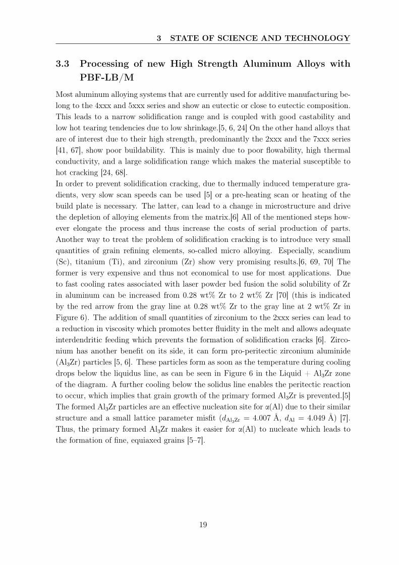
Most aluminum alloying systems that are currently used for additive manufacturing be-long to the 4xxx and 5xxx series and show an eutectic or close to eutectic composition.This leads to a narrow solidification range and is coupled with good castability andlow hot tearing tendencies due to low shrinkage.[5, 6, 24] On the other hand alloys thatare of interest due to their high strength, predominantly the 2xxx and the 7xxx series[41, 67], show poor buildability. This is mainly due to poor flowability, high thermalconductivity, and a large solidification range which makes the material susceptible tohot cracking [24, 68].In order to prevent solidification cracking, due to thermally induced temperature gra-dients, very slow scan speeds can be used [5] or a pre-heating scan or heating of thebuild plate is necessary. The latter, can lead to a change in microstructure and drivethe depletion of alloying elements from the matrix.[6] All of the mentioned steps how-ever elongate the process and thus increase the costs of serial production of parts.Another way to treat the problem of solidification cracking is to introduce very smallquantities of grain refining elements, so-called micro alloying. Especially, scandium(Sc), titanium (Ti), and zirconium (Zr) show very promising results.[6, 69, 70] Theformer is very expensive and thus not economical to use for most applications. Dueto fast cooling rates associated with laser powder bed fusion the solid solubility of Zrin aluminum can be increased from 0.28 wt% Zr to 2 wt% Zr [70] (this is indicatedby the red arrow from the gray line at 0.28 wt% Zr to the gray line at 2 wt% Zr inFigure 6). The addition of small quantities of zirconium to the 2xxx series can lead toa reduction in viscosity which promotes better fluidity in the melt and allows adequateinterdendritic feeding which prevents the formation of solidification cracks [6]. Zirco-nium has another benefit on its side, it can form pro-peritectic zirconium aluminide(Al3Zr) particles [5, 6]. These particles form as soon as the temperature during coolingdrops below the liquidus line, as can be seen in Figure 6 in the Liquid + Al3Zr zoneof the diagram. A further cooling below the solidus line enables the peritectic reactionto occur, which implies that grain growth of the primary formed Al3Zr is prevented.[5]The formed Al3Zr particles are an effective nucleation site for α(Al) due to their similarstructure and a small lattice parameter misfit (dAl3Zr = 4.007 Å, dAl = 4.049 Å) [7].Thus, the primary formed Al3Zr makes it easier for α(Al) to nucleate which leads tothe formation of fine, equiaxed grains [5–7].
19
3 STATE OF SCIENCE AND TECHNOLOGY
Figure 6: The shift of solubility of zirconium in aluminum is indicated by the red arrowfrom 0.28 wt% Zr to 2 wt% Zr and is due to fast cooling rates associated with additivemanufacturing. Own representation based on [70]
3.4 Conclusion
Research on alloys that belong to high strength aluminum alloys is currently carriedout. It has been found that the addition of grain refining elements can successfullyreduce the susceptibility to cracking during PBF-LB/M. However, during these studiesthe choice of processing gas and its influence was not discussed. This study aimsto determine the role of the shielding gas on an Zr-modified Al alloy belonging tothe 2000 series. Further, the influence of the process gas on the process-by-productformation is scarce. It is, therefore, needed to analyze the influence of the process gason the formation of process-by-products. Furthermore, the link between process gasand process-by-products characteristics is lacking, especially for high strength Al-alloysbelonging to the 2xxx series.
20
4 METHODOLOGY
4 Methodology
4.1 Resources
4.1.1 Manufacturing Machine Aconity Mini
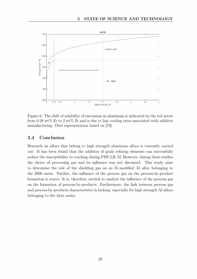
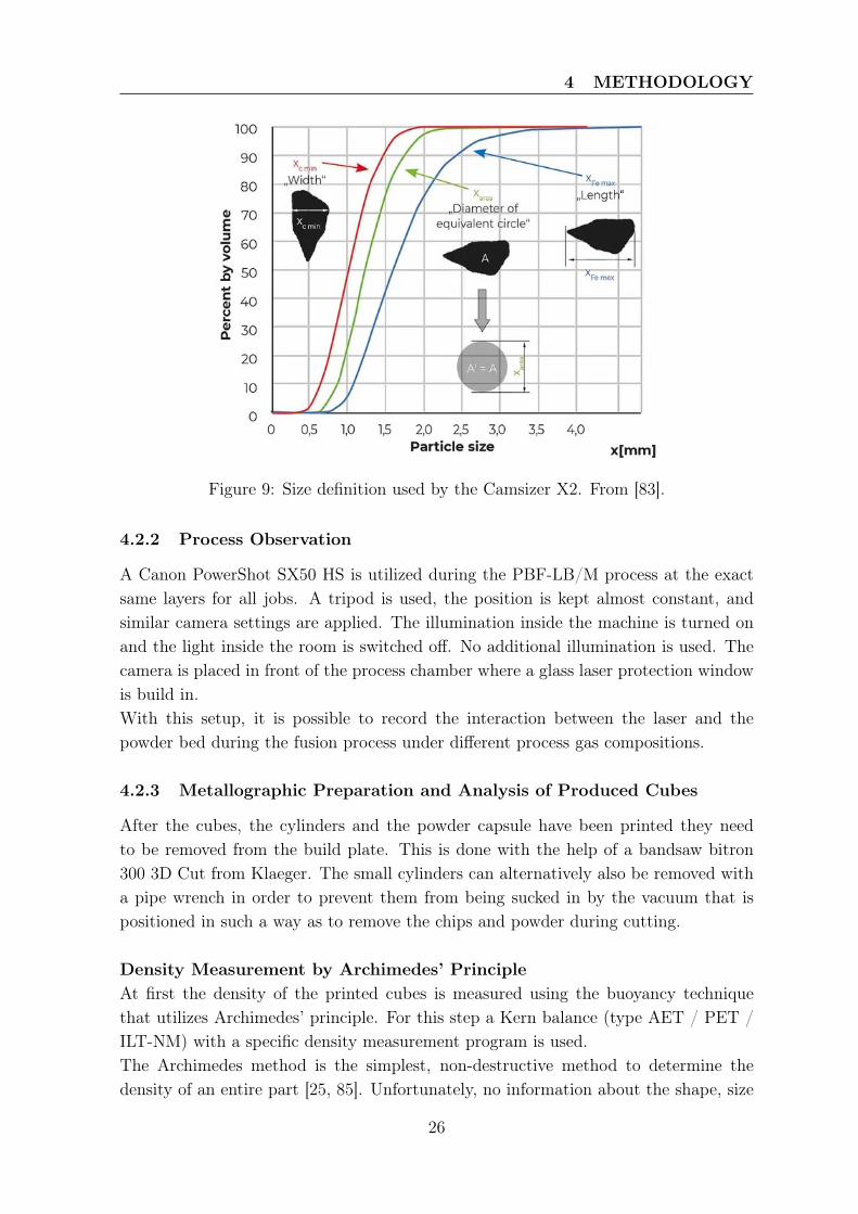
For all the builds, as described in Section 5.2.1, an Aconity Mini from Aconity is used(see Figure 7). This machine is specially designed for material research purposes dueto its small build chamber that allows for quick changes of the process.[71]. To preparethe build jobs and assign the parameter, the two software solutions Materialse Magicsand Aconity Studio are used.
Figure 7: Aconity Mini additive manufacturing system. From [71].
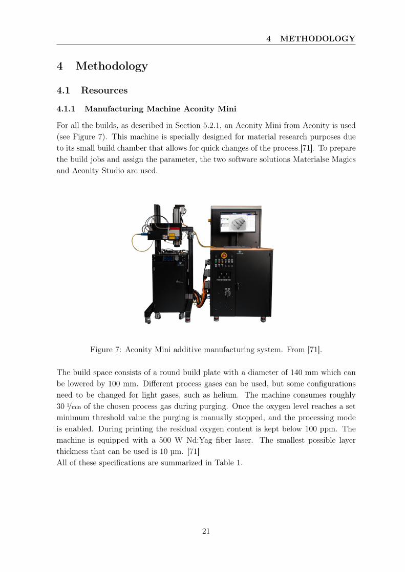
The build space consists of a round build plate with a diameter of 140 mm which canbe lowered by 100 mm. Different process gases can be used, but some configurationsneed to be changed for light gases, such as helium. The machine consumes roughly30 l/min of the chosen process gas during purging. Once the oxygen level reaches a setminimum threshold value the purging is manually stopped, and the processing modeis enabled. During printing the residual oxygen content is kept below 100 ppm. Themachine is equipped with a 500 W Nd:Yag fiber laser. The smallest possible layerthickness that can be used is 10 µm. [71]All of these specifications are summarized in Table 1.
21
4 METHODOLOGY
Table 1: Specification of the Aconity Mini from [71]Specification DimensionMachine dimensions (W x D x H) 2450 mm x 1500 mm x 2320 mmBuild space �140 mm x 80 mmResidual oxygen content <100 ppmInert gas consumption < 30 l/min during purgingLaser configuration Nd:YAG fiber laser / 500 WScan speed Maximum 12000 mm/sLaser spot size 50 - 500 µm
4.1.2 Material: 2000 series
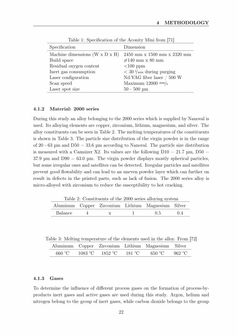
During this study an alloy belonging to the 2000 series which is supplied by Nanoval isused. Its alloying elements are copper, zirconium, lithium, magnesium, and silver. Thealloy constituents can be seen in Table 2. The melting temperatures of the constituentsis shown in Table 3. The particle size distribution of the virgin powder is in the rangeof 20 - 63 µm and D50 = 33.6 µm according to Nanoval. The particle size distributionis measured with a Camsizer X2. Its values are the following D10 = 21.7 µm, D50 =37.9 µm and D90 = 63.0 µm. The virgin powder displays mostly spherical particles,but some irregular ones and satellites can be detected. Irregular particles and satellitesprevent good flowability and can lead to an uneven powder layer which can further onresult in defects in the printed parts, such as lack of fusion. The 2000 series alloy ismicro-alloyed with zirconium to reduce the susceptibility to hot cracking.
Table 2: Constituents of the 2000 series alloying systemAluminum Copper Zirconium Lithium Magnesium SilverBalance 4 x 1 0.5 0.4
Table 3: Melting temperature of the elements used in the alloy. From [72]Aluminum Copper Zirconium Lithium Magnesium Silver660 °C 1083 °C 1852 °C 181 °C 650 °C 962 °C
4.1.3 Gases
To determine the influence of different process gases on the formation of process-by-products inert gases and active gases are used during this study. Argon, helium andnitrogen belong to the group of inert gases, while carbon dioxide belongs to the group
22
4 METHODOLOGY
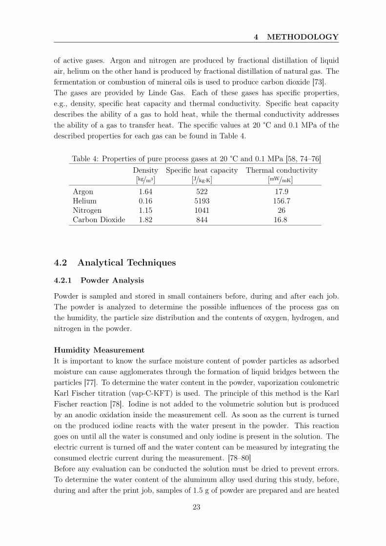
of active gases. Argon and nitrogen are produced by fractional distillation of liquidair, helium on the other hand is produced by fractional distillation of natural gas. Thefermentation or combustion of mineral oils is used to produce carbon dioxide [73].The gases are provided by Linde Gas. Each of these gases has specific properties,e.g., density, specific heat capacity and thermal conductivity. Specific heat capacitydescribes the ability of a gas to hold heat, while the thermal conductivity addressesthe ability of a gas to transfer heat. The specific values at 20 °C and 0.1 MPa of thedescribed properties for each gas can be found in Table 4.
Table 4: Properties of pure process gases at 20 °C and 0.1 MPa [58, 74–76]Density Specific heat capacity Thermal conductivity[kg/m3] [J/kg·K] [mW/mK]
Argon 1.64 522 17.9Helium 0.16 5193 156.7Nitrogen 1.15 1041 26Carbon Dioxide 1.82 844 16.8
4.2 Analytical Techniques
4.2.1 Powder Analysis
Powder is sampled and stored in small containers before, during and after each job.The powder is analyzed to determine the possible influences of the process gas onthe humidity, the particle size distribution and the contents of oxygen, hydrogen, andnitrogen in the powder.
Humidity MeasurementIt is important to know the surface moisture content of powder particles as adsorbedmoisture can cause agglomerates through the formation of liquid bridges between theparticles [77]. To determine the water content in the powder, vaporization coulometricKarl Fischer titration (vap-C-KFT) is used. The principle of this method is the KarlFischer reaction [78]. Iodine is not added to the volumetric solution but is producedby an anodic oxidation inside the measurement cell. As soon as the current is turnedon the produced iodine reacts with the water present in the powder. This reactiongoes on until all the water is consumed and only iodine is present in the solution. Theelectric current is turned off and the water content can be measured by integrating theconsumed electric current during the measurement. [78–80]Before any evaluation can be conducted the solution must be dried to prevent errors.To determine the water content of the aluminum alloy used during this study, before,during and after the print job, samples of 1.5 g of powder are prepared and are heated
23
4 METHODOLOGY
by the analysis machine to 280 °C. A blank is used to determine the moisture content ofthe atmosphere and to calibrate the measurement of the samples. The measured watercontent can directly be read from the device. The vap-C-KFT is able to determinecontents from 1 ppm up to 5 %. [79]
Carrier Gas Hot ExtractionTo determine the contents of oxygen (O2), nitrogen (N2), and hydrogen (H2) of thecollected samples an elemental analyzer is used. With the help of the carrier gas hotextraction, which is also called the inert gas fusion technique it is possible to determinethe oxygen, nitrogen and hydrogen content in a sample [81, 82].A graphite crucible is placed inside an impulse furnace and is heated to approximately3000 °C. Helium flows over the crucible and removes any contaminants that might bepresent in the crucible. This process is called "out-gassing". Once out-gassing is com-pleted the temperature is lowered and a nickel capsule containing the sample is addedto the crucible from above. The sample is melted, and O2, N2 and H2 are released fromthe sample into the inert helium atmosphere. The target gases are carried away fromthe sample out of the chamber in an inert carrier gas flow. O2 reacts with graphitefrom the crucible and forms CO and CO2. They are carried through a mass flow con-troller through a series of non-dispersive infrared (NDIR) cells. After that gas is carriedthrough a heated reagent where CO and H2 are oxidized to form CO2 and H2O. Thesethen flow through another set of NDIR cells where CO2 and H2O is detected. After thisstep CO2 and H2O are then removed from the gas stream by a scrubber and only N2
is left in the gas stream. N2 is detected by means of a thermal conductivity detector.[81, 82]In this study the LECO ONH 836 Oxygen/Nitrogen/Hydrogen is used to chemically an-alyze the powder samples, spatters, and printed material. Before any measurement canbe performed the machine needs to be cleaned thoroughly. Then blank measurementsare performed. Subsequently a standard with known oxygen, nitrogen and hydrogencontent is measured to calibrate the machine. Lastly, the sample can be analyzed.Therefore, a specified amount of powder is added to the nickel capsule and its O2, N2,H2 content is determined. For means of statistical significance at least three specimensper sample must be analyzed.
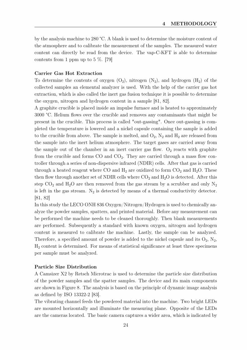
Particle Size DistributionA Camsizer X2 by Retsch Microtrac is used to determine the particle size distributionof the powder samples and the spatter samples. The device and its main componentsare shown in Figure 8. The analysis is based on the principle of dynamic image analysisas defined by ISO 13322-2 [83].The vibrating channel feeds the powdered material into the machine. Two bright LEDsare mounted horizontally and illuminate the measuring plane. Opposite of the LEDsare the cameras located. The basic camera captures a wider area, which is indicated by
24
4 METHODOLOGY
Figure 8: Camsizer X2 by Retsch Microtrac. The main components for the analysis ofpowder samples are labeled. Own representation based on [83].
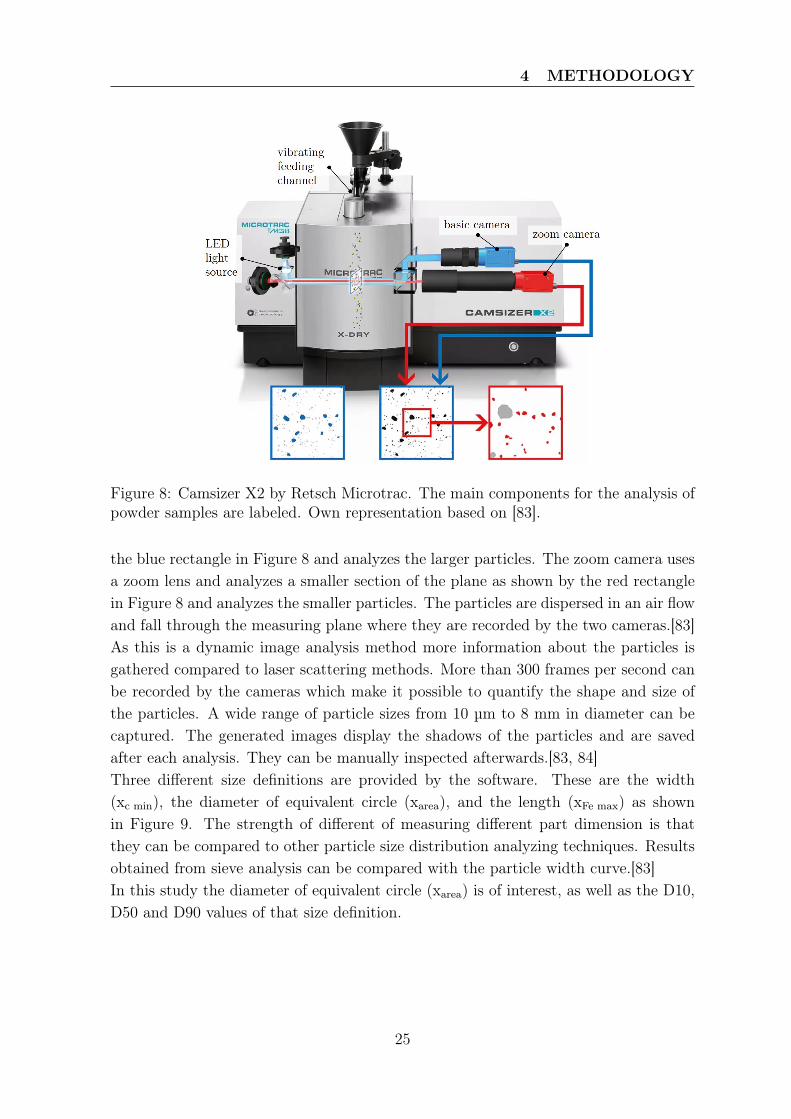
the blue rectangle in Figure 8 and analyzes the larger particles. The zoom camera usesa zoom lens and analyzes a smaller section of the plane as shown by the red rectanglein Figure 8 and analyzes the smaller particles. The particles are dispersed in an air flowand fall through the measuring plane where they are recorded by the two cameras.[83]As this is a dynamic image analysis method more information about the particles isgathered compared to laser scattering methods. More than 300 frames per second canbe recorded by the cameras which make it possible to quantify the shape and size ofthe particles. A wide range of particle sizes from 10 µm to 8 mm in diameter can becaptured. The generated images display the shadows of the particles and are savedafter each analysis. They can be manually inspected afterwards.[83, 84]Three different size definitions are provided by the software. These are the width(xc min), the diameter of equivalent circle (xarea), and the length (xFe max) as shownin Figure 9. The strength of different of measuring different part dimension is thatthey can be compared to other particle size distribution analyzing techniques. Resultsobtained from sieve analysis can be compared with the particle width curve.[83]In this study the diameter of equivalent circle (xarea) is of interest, as well as the D10,D50 and D90 values of that size definition.
25
4 METHODOLOGY
Figure 9: Size definition used by the Camsizer X2. From [83].
4.2.2 Process Observation
A Canon PowerShot SX50 HS is utilized during the PBF-LB/M process at the exactsame layers for all jobs. A tripod is used, the position is kept almost constant, andsimilar camera settings are applied. The illumination inside the machine is turned onand the light inside the room is switched off. No additional illumination is used. Thecamera is placed in front of the process chamber where a glass laser protection windowis build in.With this setup, it is possible to record the interaction between the laser and thepowder bed during the fusion process under different process gas compositions.
4.2.3 Metallographic Preparation and Analysis of Produced Cubes
After the cubes, the cylinders and the powder capsule have been printed they needto be removed from the build plate. This is done with the help of a bandsaw bitron300 3D Cut from Klaeger. The small cylinders can alternatively also be removed witha pipe wrench in order to prevent them from being sucked in by the vacuum that ispositioned in such a way as to remove the chips and powder during cutting.
Density Measurement by Archimedes’ PrincipleAt first the density of the printed cubes is measured using the buoyancy techniquethat utilizes Archimedes’ principle. For this step a Kern balance (type AET / PET /ILT-NM) with a specific density measurement program is used.The Archimedes method is the simplest, non-destructive method to determine thedensity of an entire part [25, 85]. Unfortunately, no information about the shape, size
26
4 METHODOLOGY
or distribution of pores can be given by this method [25]. To get detailed informationother measuring techniques must be employed, one of them is described later in thisreport. If the specimen has surface breaking cracks or pores the standard deviation ofthe measured densities will be big [85]. As liquid can infiltrate the part.To determine the density of the specimen its mass in air (ma) and in a fluid (mfl) hasto be determined using an appropriate scale. The density of the fluid (ρfl) which isdependent on the temperature of the fluid has to be known as well. From this thedensity of the part (ρa) can be calculated following equation 11 [85, 86]:
ρp =ma
ma ·mfl
· ρfl (11)
In order to achieve consistent results the liquid used, here ethanol, has to be in ther-mal equilibrium with the laboratory air, as well as the specimens being tested. Thetemperature of the fluid should be taken into account and each sample should be mea-sured at least three times. The average over the three measurements is then taken andits standard deviation calculated and reported. Care should be taken to prevent airbubbles from sticking to the surface and screwing the measurement. Therefore, thesurface of the cubes is smoothened using a SiC Paper Grit 220 utilizing a grinding andpolishing machine (Tegramin-25).
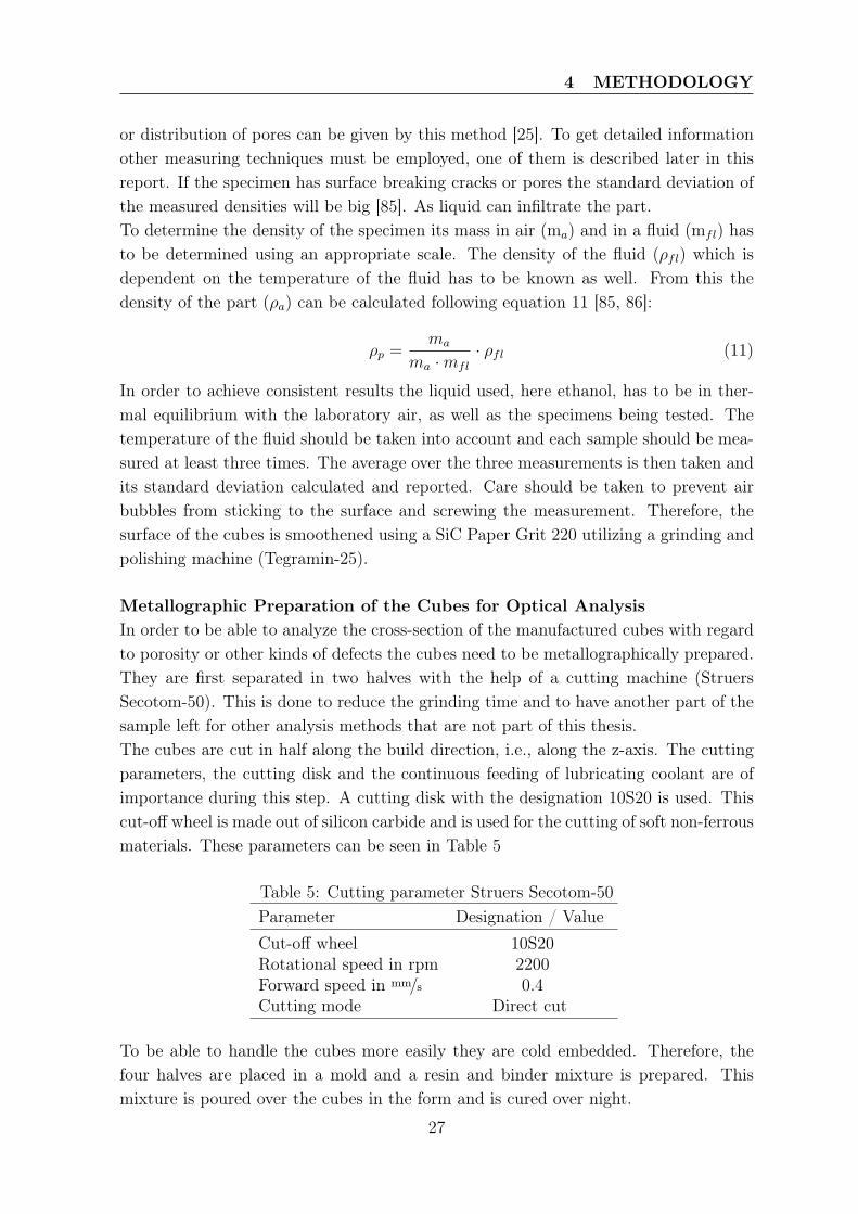
Metallographic Preparation of the Cubes for Optical AnalysisIn order to be able to analyze the cross-section of the manufactured cubes with regardto porosity or other kinds of defects the cubes need to be metallographically prepared.They are first separated in two halves with the help of a cutting machine (StruersSecotom-50). This is done to reduce the grinding time and to have another part of thesample left for other analysis methods that are not part of this thesis.The cubes are cut in half along the build direction, i.e., along the z-axis. The cuttingparameters, the cutting disk and the continuous feeding of lubricating coolant are ofimportance during this step. A cutting disk with the designation 10S20 is used. Thiscut-off wheel is made out of silicon carbide and is used for the cutting of soft non-ferrousmaterials. These parameters can be seen in Table 5
Table 5: Cutting parameter Struers Secotom-50Parameter Designation / ValueCut-off wheel 10S20Rotational speed in rpm 2200Forward speed in mm/s 0.4Cutting mode Direct cut
To be able to handle the cubes more easily they are cold embedded. Therefore, thefour halves are placed in a mold and a resin and binder mixture is prepared. Thismixture is poured over the cubes in the form and is cured over night.
27
4 METHODOLOGY
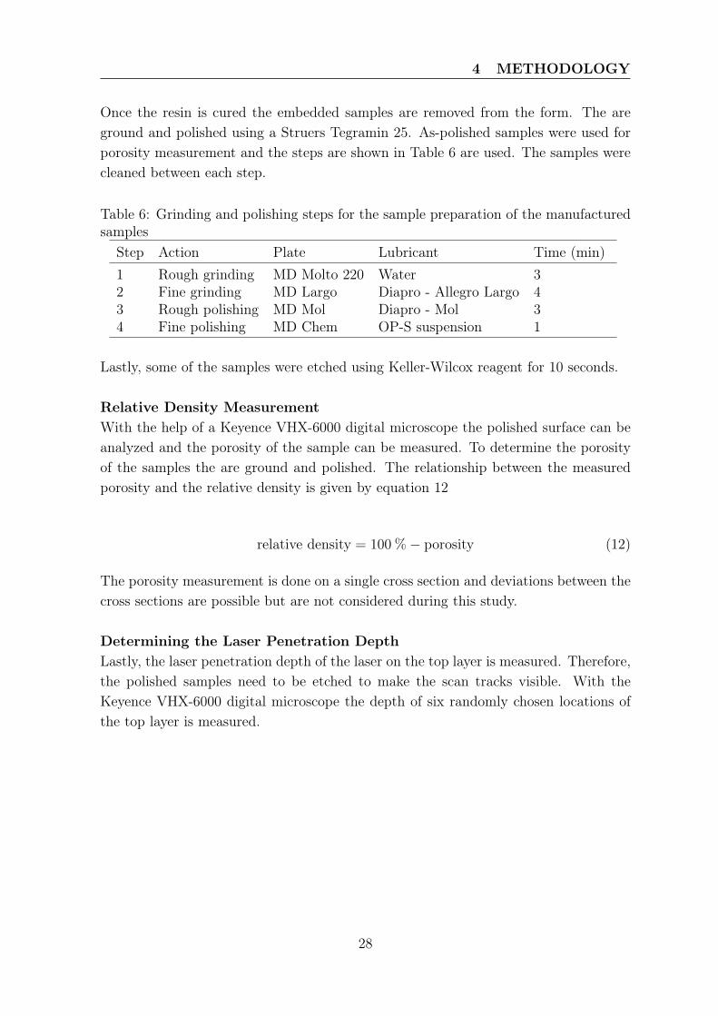
Once the resin is cured the embedded samples are removed from the form. The areground and polished using a Struers Tegramin 25. As-polished samples were used forporosity measurement and the steps are shown in Table 6 are used. The samples werecleaned between each step.
Table 6: Grinding and polishing steps for the sample preparation of the manufacturedsamples
Step Action Plate Lubricant Time (min)1 Rough grinding MD Molto 220 Water 32 Fine grinding MD Largo Diapro - Allegro Largo 43 Rough polishing MD Mol Diapro - Mol 34 Fine polishing MD Chem OP-S suspension 1
Lastly, some of the samples were etched using Keller-Wilcox reagent for 10 seconds.
Relative Density MeasurementWith the help of a Keyence VHX-6000 digital microscope the polished surface can beanalyzed and the porosity of the sample can be measured. To determine the porosityof the samples the are ground and polished. The relationship between the measuredporosity and the relative density is given by equation 12
relative density = 100 %− porosity (12)
The porosity measurement is done on a single cross section and deviations between thecross sections are possible but are not considered during this study.
Determining the Laser Penetration DepthLastly, the laser penetration depth of the laser on the top layer is measured. Therefore,the polished samples need to be etched to make the scan tracks visible. With theKeyence VHX-6000 digital microscope the depth of six randomly chosen locations ofthe top layer is measured.
28
5 EXPERIMENTAL SETUP
5 Experimental Setup
5.1 Statistics
5.1.1 Design of Experiments
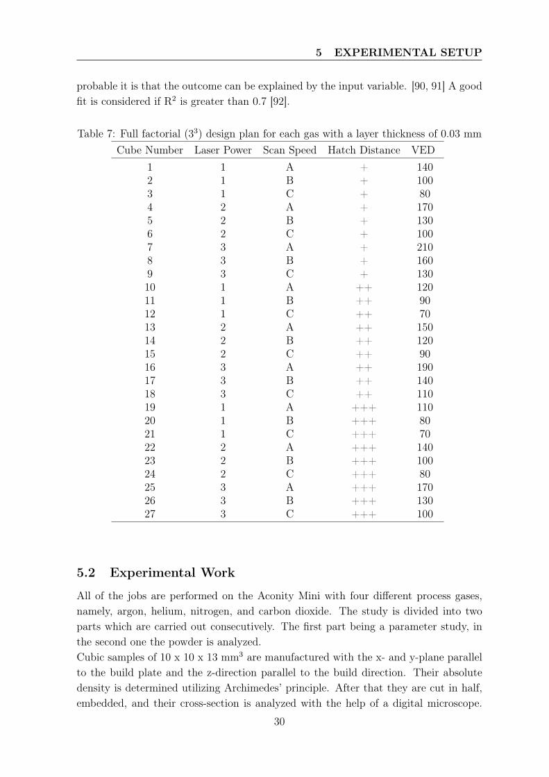
Different types of experiments are known to researchers, those are the best-guessapproach, which can also be called trial-and-error method, the one-factor-at-a-timemethod, and the design of experiments. The latter is a statistical method developedduring 1920 - 1930 by Sir Fisher.[87]The trial and error method is often used and can obtain reasonable results if the re-searcher has in-depth knowledge. However, this method is very time consuming, has noguarantee for success and is influenced by the experimenter. The obtained results needto be accepted by the researcher and could thus not be the best possible outcome.[87]During the one-factor-at-a-time approach, one factor is varied while the others are keptconstant. Once that is done, another factor is varied while the rest is constant andso on until every factor is altered. The response of the target variable to altering theinput variables is analyzed. The method however neglects the interaction between thefactors. [87]In a factorial design of experiments (DoE) the different variables are varied simultane-ously and their effect on the target variable is investigated. The interactions betweenthe input variables occur frequently and are taken into consideration when analyzingthe output. Thus, when dealing with many factors during an experiment the methodof choice is factorial design of experiments. [87]For this study a three level three factors (33) DoE is chosen for each gas. The designis shown in Table 7. As the exact parameter are not yet published they are decodedand the VEDs are rounded.
5.1.2 Statistical Evaluation
To determine the influence of each input variable (laser power, scan speed, hatch dis-tance) on to the output variable (Archimedes density, relative density, penetrationdepth) the output is plotted against the input. A linear regression is performed, and a95% confidence interval is added to each plot.The confidence interval (CI) is computed from the given data. It estimates how plau-sible it is that the true value of a parameter is contained within the interval. Valuesoutside the interval are relatively implausible. Whereas values in the interval can beassumed to be true. The shorter the interval the higher the probability that the valuein the interval is true. [88, 89]Furthermore R-squared (R2) is determined which describes the goodness-of-fit of thelinear regression. R2 is given in percentage and describes the variation in the outputvariable by the input variables. Thus, the higher the value of R-squared the more
29
5 EXPERIMENTAL SETUP
probable it is that the outcome can be explained by the input variable. [90, 91] A goodfit is considered if R2 is greater than 0.7 [92].
Table 7: Full factorial (33) design plan for each gas with a layer thickness of 0.03 mmCube Number Laser Power Scan Speed Hatch Distance VED
1 1 A + 1402 1 B + 1003 1 C + 804 2 A + 1705 2 B + 1306 2 C + 1007 3 A + 2108 3 B + 1609 3 C + 13010 1 A ++ 12011 1 B ++ 9012 1 C ++ 7013 2 A ++ 15014 2 B ++ 12015 2 C ++ 9016 3 A ++ 19017 3 B ++ 14018 3 C ++ 11019 1 A +++ 11020 1 B +++ 8021 1 C +++ 7022 2 A +++ 14023 2 B +++ 10024 2 C +++ 8025 3 A +++ 17026 3 B +++ 13027 3 C +++ 100
5.2 Experimental Work
All of the jobs are performed on the Aconity Mini with four different process gases,namely, argon, helium, nitrogen, and carbon dioxide. The study is divided into twoparts which are carried out consecutively. The first part being a parameter study, inthe second one the powder is analyzed.Cubic samples of 10 x 10 x 13 mm3 are manufactured with the x- and y-plane parallelto the build plate and the z-direction parallel to the build direction. Their absolutedensity is determined utilizing Archimedes’ principle. After that they are cut in half,embedded, and their cross-section is analyzed with the help of a digital microscope.
30
5 EXPERIMENTAL SETUP
The relative density is determined, and some cross-sections are etched to analyze thepenetration depth of the laser on the last produced layer.In order to collect powder under printing conditions a hollow powder capsule is addedto each job. The powder capsule is manufactured with the parameter set 9. Thepowder is collected continuously during each recoating step during the job and can beanalyzed afterwards. This method ensures that the powder contamination by air iskept to a minimum compared to sampling powder after the print job from the powderbed. However, powder sampled after the job, directly from the powder bed, is analyzed,as well. The same is true for the virgin powder collected from the powder reservoirbefore each job. For these samples the particle size distribution, humidity and O2, N2
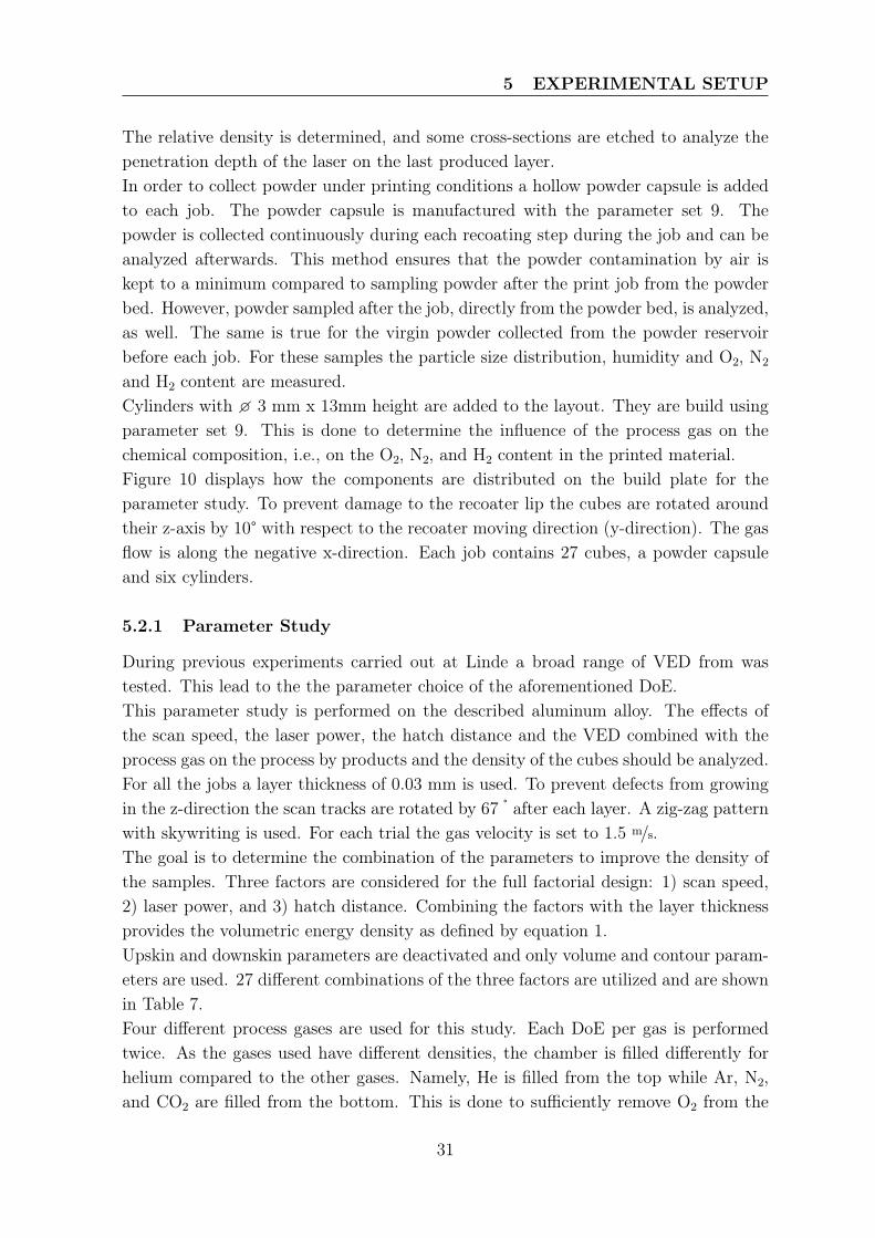
and H2 content are measured.Cylinders with � 3 mm x 13mm height are added to the layout. They are build usingparameter set 9. This is done to determine the influence of the process gas on thechemical composition, i.e., on the O2, N2, and H2 content in the printed material.Figure 10 displays how the components are distributed on the build plate for theparameter study. To prevent damage to the recoater lip the cubes are rotated aroundtheir z-axis by 10° with respect to the recoater moving direction (y-direction). The gasflow is along the negative x-direction. Each job contains 27 cubes, a powder capsuleand six cylinders.
5.2.1 Parameter Study
During previous experiments carried out at Linde a broad range of VED from wastested. This lead to the the parameter choice of the aforementioned DoE.This parameter study is performed on the described aluminum alloy. The effects ofthe scan speed, the laser power, the hatch distance and the VED combined with theprocess gas on the process by products and the density of the cubes should be analyzed.For all the jobs a layer thickness of 0.03 mm is used. To prevent defects from growingin the z-direction the scan tracks are rotated by 67 ° after each layer. A zig-zag patternwith skywriting is used. For each trial the gas velocity is set to 1.5 m/s.The goal is to determine the combination of the parameters to improve the density ofthe samples. Three factors are considered for the full factorial design: 1) scan speed,2) laser power, and 3) hatch distance. Combining the factors with the layer thicknessprovides the volumetric energy density as defined by equation 1.Upskin and downskin parameters are deactivated and only volume and contour param-eters are used. 27 different combinations of the three factors are utilized and are shownin Table 7.Four different process gases are used for this study. Each DoE per gas is performedtwice. As the gases used have different densities, the chamber is filled differently forhelium compared to the other gases. Namely, He is filled from the top while Ar, N2,and CO2 are filled from the bottom. This is done to sufficiently remove O2 from the
31
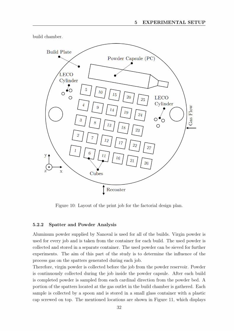
5 EXPERIMENTAL SETUP
build chamber.
Figure 10: Layout of the print job for the factorial design plan.
5.2.2 Spatter and Powder Analysis
Aluminum powder supplied by Nanoval is used for all of the builds. Virgin powder isused for every job and is taken from the container for each build. The used powder iscollected and stored in a separate container. The used powder can be sieved for furtherexperiments. The aim of this part of the study is to determine the influence of theprocess gas on the spatters generated during each job.Therefore, virgin powder is collected before the job from the powder reservoir. Powderis continuously collected during the job inside the powder capsule. After each buildis completed powder is sampled from each cardinal direction from the powder bed. Aportion of the spatters located at the gas outlet in the build chamber is gathered. Eachsample is collected by a spoon and is stored in a small glass container with a plasticcap screwed on top. The mentioned locations are shown in Figure 11, which displays
32
5 EXPERIMENTAL SETUP
the build chamber after a job is performed.For the collected samples, the PSD, the humidity, and the chemical composition isdetermined.
Figure 11: Build space of the Aconity Mini with the areas marked where powder issampled from after the build job is performed.
33
6 RESULTS
6 Results
For each gas used as a shielding gas during the process, a powder capsule was addedto the build. Due the duration of each job (approximately 9.5h) and the potentialrisk of having an unattended cylinder of CO2 gas standing in the lab overnight, thepowder capsule was removed from the builds under CO2. Further as aforementionedeach shielding gas was used twice. As the results obtained after each trial are in goodaccordance with each other the mean of the two jobs, per shielding gas, is shown inthis section.
6.1 Process Observations
A camera was used to film the interaction between the laser and the powder bed duringeach trial. The video is converted into images so that they are easier to view. Only avisual analysis is performed without the usage of a software.The images shown in Figure 12 are of the cube number 10 under (a) Ar, (b) N2, (c) He,and (d) CO2 shielding.The first noticeable difference between the different shielding gases is that the raysshown in 12 (a), (b) and (d) are much longer than those shown in (c).Furthermore, the rays shown in (a) have a higher curvature to the left (along the gasstream) compared to the ones shown in (b) which seem to have a lower curvature andare bent further above the powder bed - laser interaction plane. In (c) a curvature isnot visible, the rays are probably not long enough to show any kind of curvature andthe density of He is lowest compared to the other gases. In (d) the bending of the raysis clearly visible.Another difference visible between the different gases is the color of the rays. UnderAr, N2 and He shielding the rays have a reddish color, while the rays under CO2 aremore on the yellowish side.Lastly the number of incandescent particles visible in each frame is noticeably different.Under He shielding the lowest number of incandescent particles can be seen, under Arand N2 shielding the number of bright, glowing particles is increased compared to He,but is roughly the same. Under CO2 shielding the number of incandescent particles isincreased and shows the highest number of glowing and light emitting particles.Under all gases interactions between cold particles that are being sucked from thepowder bed into the laser beam due to the presence of a vapor jet can be seen. Theseparticles interact with the laser beam and go from cold particles to incandescent ones.
34
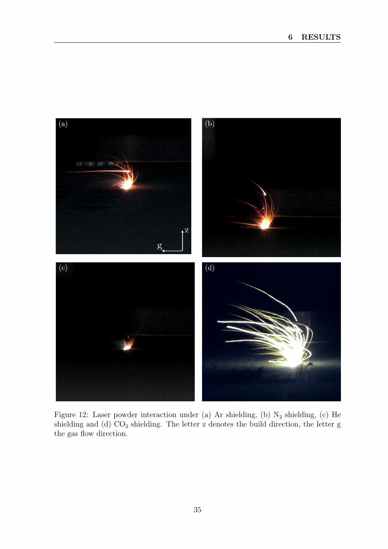
6 RESULTS
Figure 12: Laser powder interaction under (a) Ar shielding, (b) N2 shielding, (c) Heshielding and (d) CO2 shielding. The letter z denotes the build direction, the letter gthe gas flow direction.
35
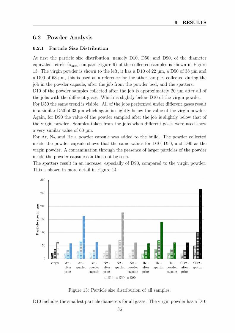
6 RESULTS
6.2 Powder Analysis
6.2.1 Particle Size Distribution
At first the particle size distribution, namely D10, D50, and D90, of the diameterequivalent circle (xarea compare Figure 9) of the collected samples is shown in Figure13. The virgin powder is shown to the left, it has a D10 of 22 µm, a D50 of 38 µm anda D90 of 63 µm, this is used as a reference for the other samples collected during thejob in the powder capsule, after the job from the powder bed, and the spatters.D10 of the powder samples collected after the job is approximately 20 µm after all ofthe jobs with the different gases. Which is slightly below D10 of the virgin powder.For D50 the same trend is visible. All of the jobs performed under different gases resultin a similar D50 of 33 µm which again is slightly below the value of the virgin powder.Again, for D90 the value of the powder sampled after the job is slightly below that ofthe virgin powder. Samples taken from the jobs when different gases were used showa very similar value of 60 µm.For Ar, N2, and He a powder capsule was added to the build. The powder collectedinside the powder capsule shows that the same values for D10, D50, and D90 as thevirgin powder. A contamination through the presence of larger particles of the powderinside the powder capsule can thus not be seen.The spatters result in an increase, especially of D90, compared to the virgin powder.This is shown in more detail in Figure 14.
Figure 13: Particle size distribution of all samples.
D10 includes the smallest particle diameters for all gases. The virgin powder has a D10
36
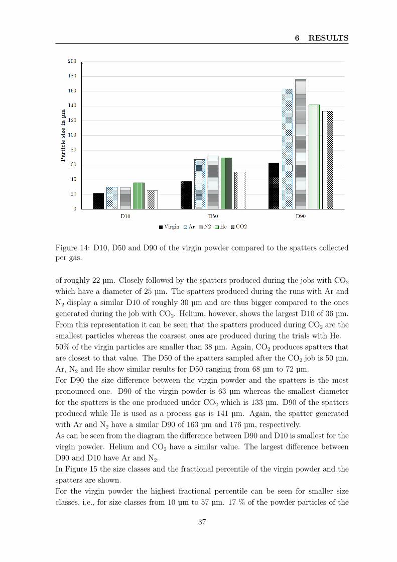
6 RESULTS
Figure 14: D10, D50 and D90 of the virgin powder compared to the spatters collectedper gas.
of roughly 22 µm. Closely followed by the spatters produced during the jobs with CO2
which have a diameter of 25 µm. The spatters produced during the runs with Ar andN2 display a similar D10 of roughly 30 µm and are thus bigger compared to the onesgenerated during the job with CO2. Helium, however, shows the largest D10 of 36 µm.From this representation it can be seen that the spatters produced during CO2 are thesmallest particles whereas the coarsest ones are produced during the trials with He.50% of the virgin particles are smaller than 38 µm. Again, CO2 produces spatters thatare closest to that value. The D50 of the spatters sampled after the CO2 job is 50 µm.Ar, N2 and He show similar results for D50 ranging from 68 µm to 72 µm.For D90 the size difference between the virgin powder and the spatters is the mostpronounced one. D90 of the virgin powder is 63 µm whereas the smallest diameterfor the spatters is the one produced under CO2 which is 133 µm. D90 of the spattersproduced while He is used as a process gas is 141 µm. Again, the spatter generatedwith Ar and N2 have a similar D90 of 163 µm and 176 µm, respectively.As can be seen from the diagram the difference between D90 and D10 is smallest for thevirgin powder. Helium and CO2 have a similar value. The largest difference betweenD90 and D10 have Ar and N2.In Figure 15 the size classes and the fractional percentile of the virgin powder and thespatters are shown.For the virgin powder the highest fractional percentile can be seen for smaller sizeclasses, i.e., for size classes from 10 µm to 57 µm. 17 % of the powder particles of the
37
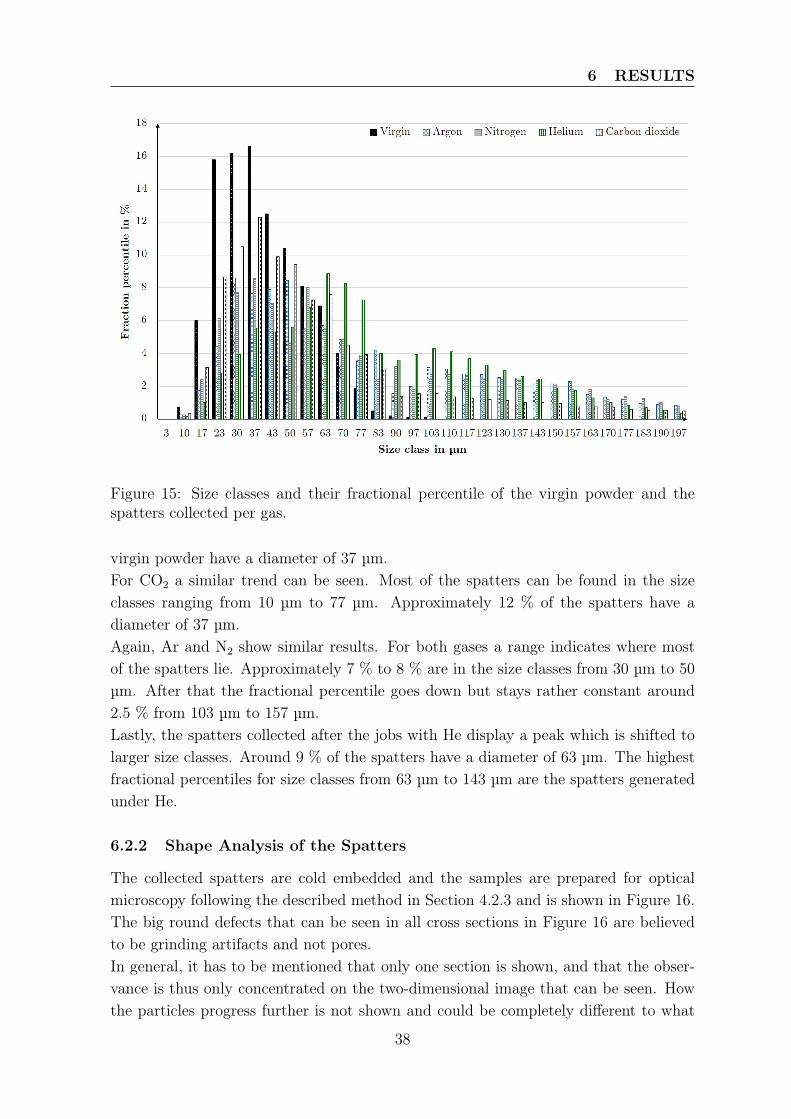
6 RESULTS
Figure 15: Size classes and their fractional percentile of the virgin powder and thespatters collected per gas.
virgin powder have a diameter of 37 µm.For CO2 a similar trend can be seen. Most of the spatters can be found in the sizeclasses ranging from 10 µm to 77 µm. Approximately 12 % of the spatters have adiameter of 37 µm.Again, Ar and N2 show similar results. For both gases a range indicates where mostof the spatters lie. Approximately 7 % to 8 % are in the size classes from 30 µm to 50µm. After that the fractional percentile goes down but stays rather constant around2.5 % from 103 µm to 157 µm.Lastly, the spatters collected after the jobs with He display a peak which is shifted tolarger size classes. Around 9 % of the spatters have a diameter of 63 µm. The highestfractional percentiles for size classes from 63 µm to 143 µm are the spatters generatedunder He.
6.2.2 Shape Analysis of the Spatters
The collected spatters are cold embedded and the samples are prepared for opticalmicroscopy following the described method in Section 4.2.3 and is shown in Figure 16.The big round defects that can be seen in all cross sections in Figure 16 are believedto be grinding artifacts and not pores.In general, it has to be mentioned that only one section is shown, and that the obser-vance is thus only concentrated on the two-dimensional image that can be seen. Howthe particles progress further is not shown and could be completely different to what
38
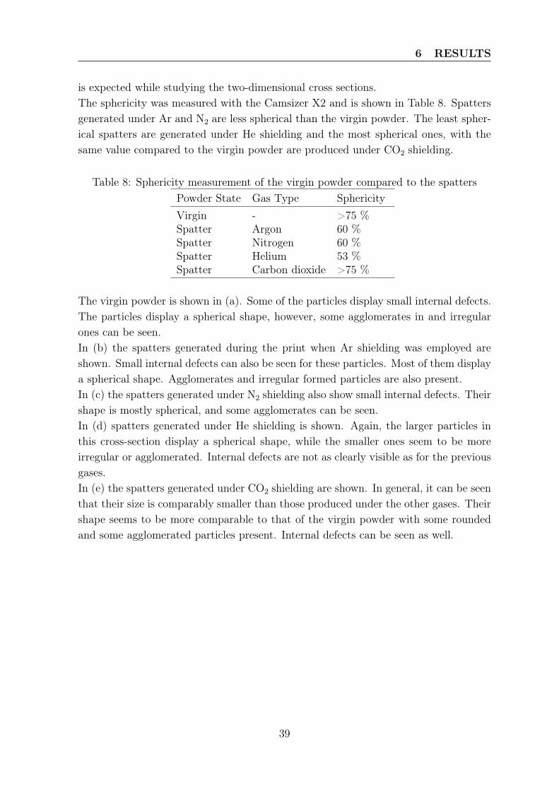
6 RESULTS
is expected while studying the two-dimensional cross sections.The sphericity was measured with the Camsizer X2 and is shown in Table 8. Spattersgenerated under Ar and N2 are less spherical than the virgin powder. The least spher-ical spatters are generated under He shielding and the most spherical ones, with thesame value compared to the virgin powder are produced under CO2 shielding.
Table 8: Sphericity measurement of the virgin powder compared to the spattersPowder State Gas Type SphericityVirgin - >75 %Spatter Argon 60 %Spatter Nitrogen 60 %Spatter Helium 53 %Spatter Carbon dioxide >75 %
The virgin powder is shown in (a). Some of the particles display small internal defects.The particles display a spherical shape, however, some agglomerates in and irregularones can be seen.In (b) the spatters generated during the print when Ar shielding was employed areshown. Small internal defects can also be seen for these particles. Most of them displaya spherical shape. Agglomerates and irregular formed particles are also present.In (c) the spatters generated under N2 shielding also show small internal defects. Theirshape is mostly spherical, and some agglomerates can be seen.In (d) spatters generated under He shielding is shown. Again, the larger particles inthis cross-section display a spherical shape, while the smaller ones seem to be moreirregular or agglomerated. Internal defects are not as clearly visible as for the previousgases.In (e) the spatters generated under CO2 shielding are shown. In general, it can be seenthat their size is comparably smaller than those produced under the other gases. Theirshape seems to be more comparable to that of the virgin powder with some roundedand some agglomerated particles present. Internal defects can be seen as well.
39
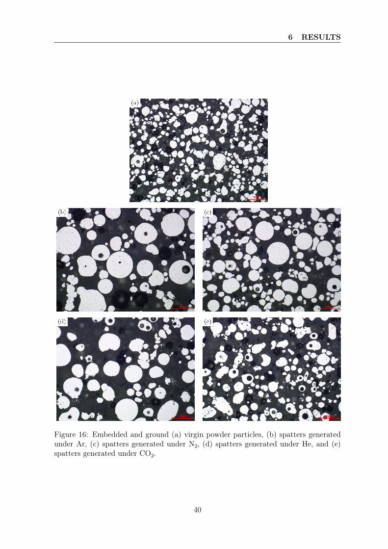
6 RESULTS
Figure 16: Embedded and ground (a) virgin powder particles, (b) spatters generatedunder Ar, (c) spatters generated under N2, (d) spatters generated under He, and (e)spatters generated under CO2.
40
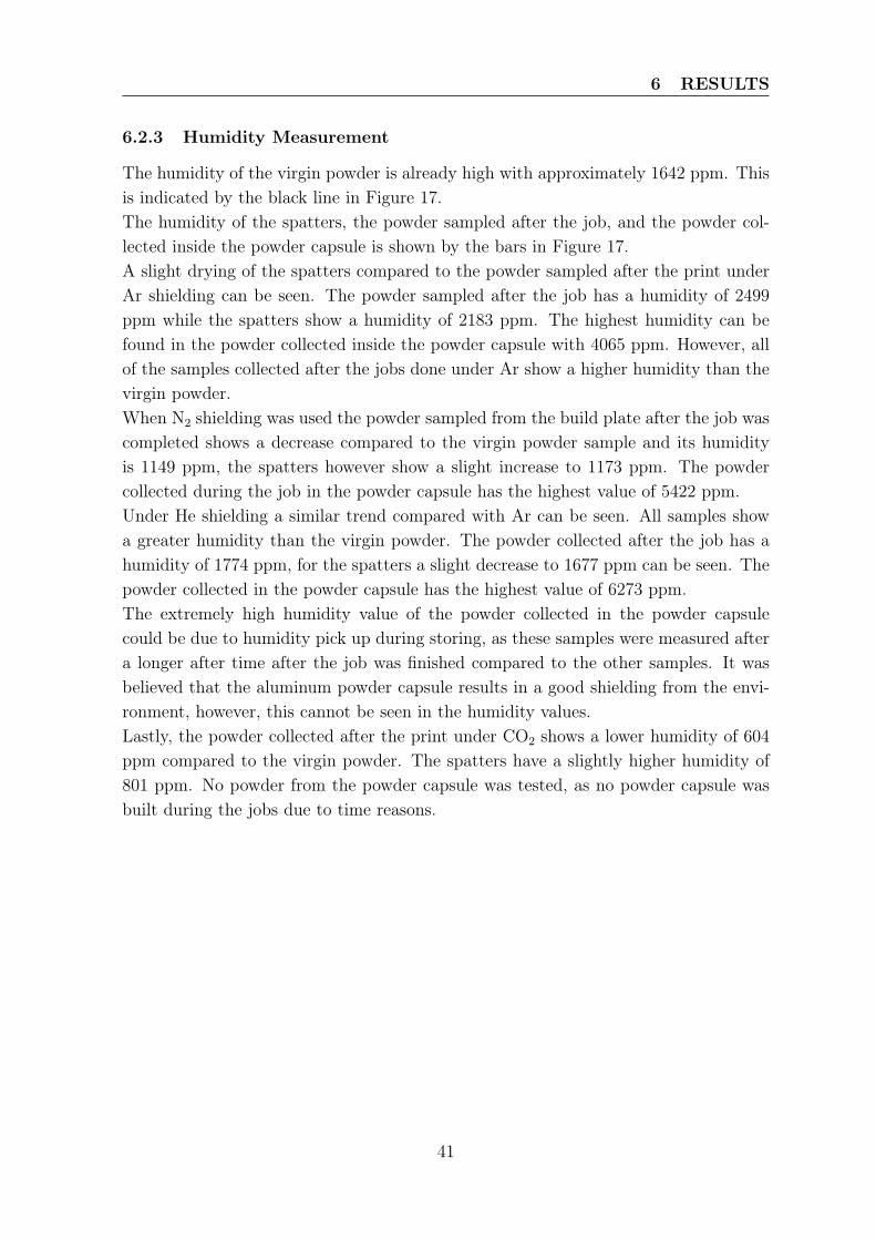
6 RESULTS
6.2.3 Humidity Measurement
The humidity of the virgin powder is already high with approximately 1642 ppm. Thisis indicated by the black line in Figure 17.The humidity of the spatters, the powder sampled after the job, and the powder col-lected inside the powder capsule is shown by the bars in Figure 17.A slight drying of the spatters compared to the powder sampled after the print underAr shielding can be seen. The powder sampled after the job has a humidity of 2499ppm while the spatters show a humidity of 2183 ppm. The highest humidity can befound in the powder collected inside the powder capsule with 4065 ppm. However, allof the samples collected after the jobs done under Ar show a higher humidity than thevirgin powder.When N2 shielding was used the powder sampled from the build plate after the job wascompleted shows a decrease compared to the virgin powder sample and its humidityis 1149 ppm, the spatters however show a slight increase to 1173 ppm. The powdercollected during the job in the powder capsule has the highest value of 5422 ppm.Under He shielding a similar trend compared with Ar can be seen. All samples showa greater humidity than the virgin powder. The powder collected after the job has ahumidity of 1774 ppm, for the spatters a slight decrease to 1677 ppm can be seen. Thepowder collected in the powder capsule has the highest value of 6273 ppm.The extremely high humidity value of the powder collected in the powder capsulecould be due to humidity pick up during storing, as these samples were measured aftera longer after time after the job was finished compared to the other samples. It wasbelieved that the aluminum powder capsule results in a good shielding from the envi-ronment, however, this cannot be seen in the humidity values.Lastly, the powder collected after the print under CO2 shows a lower humidity of 604ppm compared to the virgin powder. The spatters have a slightly higher humidity of801 ppm. No powder from the powder capsule was tested, as no powder capsule wasbuilt during the jobs due to time reasons.
41
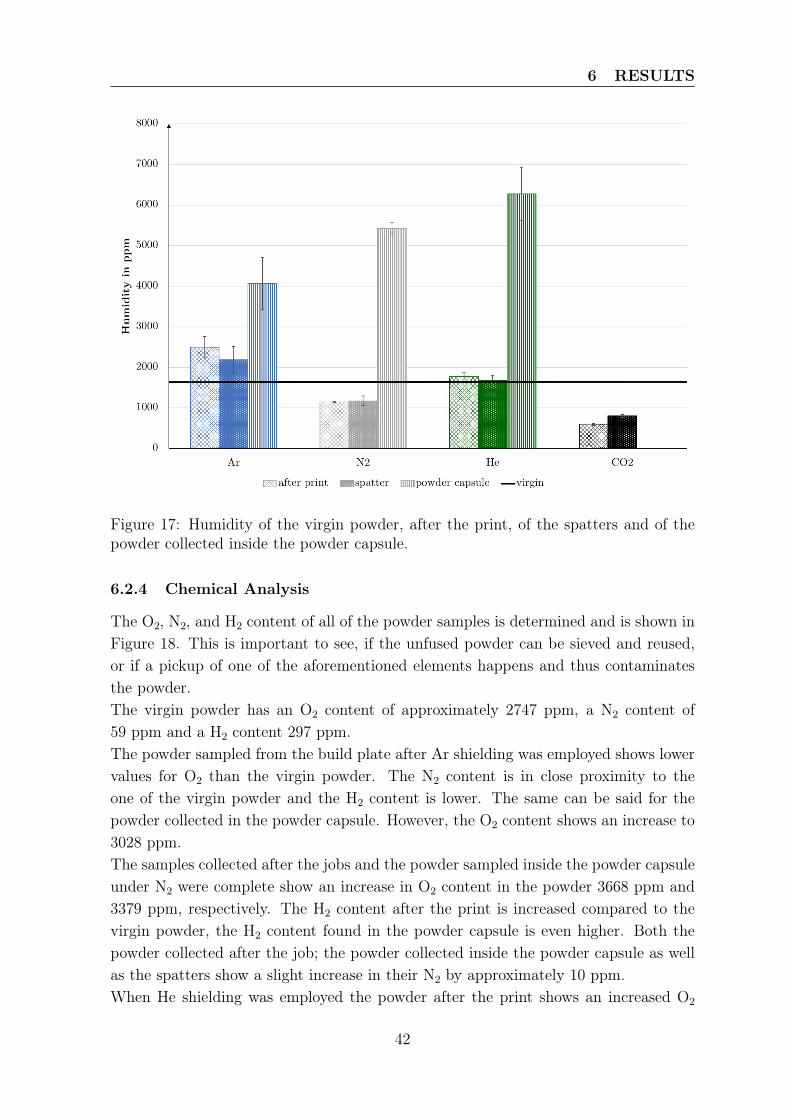
6 RESULTS
Figure 17: Humidity of the virgin powder, after the print, of the spatters and of thepowder collected inside the powder capsule.
6.2.4 Chemical Analysis
The O2, N2, and H2 content of all of the powder samples is determined and is shown inFigure 18. This is important to see, if the unfused powder can be sieved and reused,or if a pickup of one of the aforementioned elements happens and thus contaminatesthe powder.The virgin powder has an O2 content of approximately 2747 ppm, a N2 content of59 ppm and a H2 content 297 ppm.The powder sampled from the build plate after Ar shielding was employed shows lowervalues for O2 than the virgin powder. The N2 content is in close proximity to theone of the virgin powder and the H2 content is lower. The same can be said for thepowder collected in the powder capsule. However, the O2 content shows an increase to3028 ppm.The samples collected after the jobs and the powder sampled inside the powder capsuleunder N2 were complete show an increase in O2 content in the powder 3668 ppm and3379 ppm, respectively. The H2 content after the print is increased compared to thevirgin powder, the H2 content found in the powder capsule is even higher. Both thepowder collected after the job; the powder collected inside the powder capsule as wellas the spatters show a slight increase in their N2 by approximately 10 ppm.When He shielding was employed the powder after the print shows an increased O2
42
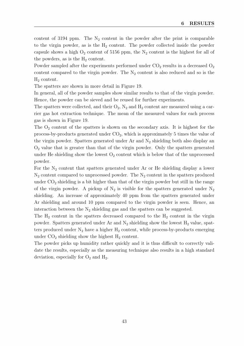
6 RESULTS
content of 3194 ppm. The N2 content in the powder after the print is comparableto the virgin powder, as is the H2 content. The powder collected inside the powdercapsule shows a high O2 content of 5156 ppm, the N2 content is the highest for all ofthe powders, as is the H2 content.Powder sampled after the experiments performed under CO2 results in a decreased O2
content compared to the virgin powder. The N2 content is also reduced and so is theH2 content.The spatters are shown in more detail in Figure 19.In general, all of the powder samples show similar results to that of the virgin powder.Hence, the powder can be sieved and be reused for further experiments.The spatters were collected, and their O2, N2 and H2 content are measured using a car-rier gas hot extraction technique. The mean of the measured values for each processgas is shown in Figure 19.The O2 content of the spatters is shown on the secondary axis. It is highest for theprocess-by-products generated under CO2, which is approximately 5 times the value ofthe virgin powder. Spatters generated under Ar and N2 shielding both also display anO2 value that is greater than that of the virgin powder. Only the spatters generatedunder He shielding show the lowest O2 content which is below that of the unprocessedpowder.For the N2 content that spatters generated under Ar or He shielding display a lowerN2 content compared to unprocessed powder. The N2 content in the spatters producedunder CO2 shielding is a bit higher than that of the virgin powder but still in the rangeof the virgin powder. A pickup of N2 is visible for the spatters generated under N2
shielding. An increase of approximately 40 ppm from the spatters generated underAr shielding and around 10 ppm compared to the virgin powder is seen. Hence, aninteraction between the N2 shielding gas and the spatters can be suggested.The H2 content in the spatters decreased compared to the H2 content in the virginpowder. Spatters generated under Ar and N2 shielding show the lowest H2 value, spat-ters produced under N2 have a higher H2 content, while process-by-products emergingunder CO2 shielding show the highest H2 content.The powder picks up humidity rather quickly and it is thus difficult to correctly vali-date the results, especially as the measuring technique also results in a high standarddeviation, especially for O2 and H2.
43
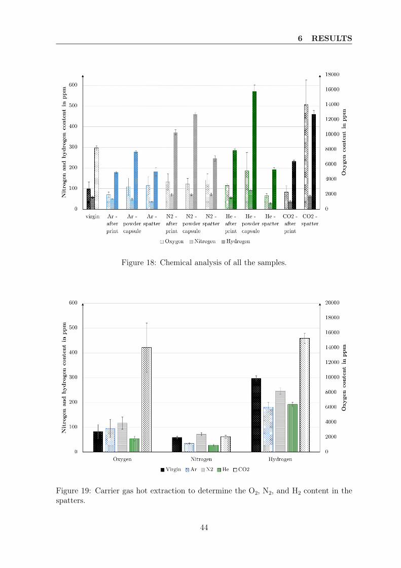
6 RESULTS
Figure 18: Chemical analysis of all the samples.
Figure 19: Carrier gas hot extraction to determine the O2, N2, and H2 content in thespatters.
44
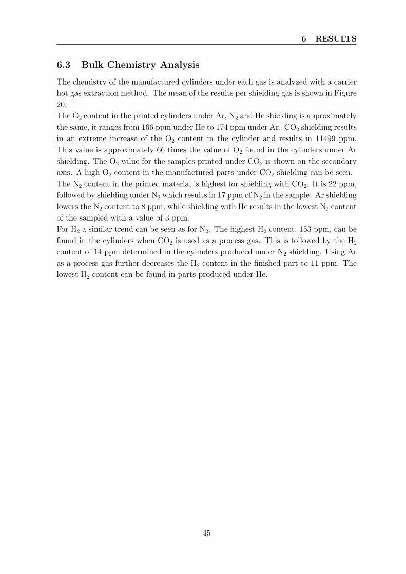
6 RESULTS
6.3 Bulk Chemistry Analysis
The chemistry of the manufactured cylinders under each gas is analyzed with a carrierhot gas extraction method. The mean of the results per shielding gas is shown in Figure20.The O2 content in the printed cylinders under Ar, N2 and He shielding is approximatelythe same, it ranges from 166 ppm under He to 174 ppm under Ar. CO2 shielding resultsin an extreme increase of the O2 content in the cylinder and results in 11499 ppm.This value is approximately 66 times the value of O2 found in the cylinders under Arshielding. The O2 value for the samples printed under CO2 is shown on the secondaryaxis. A high O2 content in the manufactured parts under CO2 shielding can be seen.The N2 content in the printed material is highest for shielding with CO2. It is 22 ppm,followed by shielding under N2 which results in 17 ppm of N2 in the sample. Ar shieldinglowers the N2 content to 8 ppm, while shielding with He results in the lowest N2 contentof the sampled with a value of 3 ppm.For H2 a similar trend can be seen as for N2. The highest H2 content, 153 ppm, can befound in the cylinders when CO2 is used as a process gas. This is followed by the H2
content of 14 ppm determined in the cylinders produced under N2 shielding. Using Aras a process gas further decreases the H2 content in the finished part to 11 ppm. Thelowest H2 content can be found in parts produced under He.
45
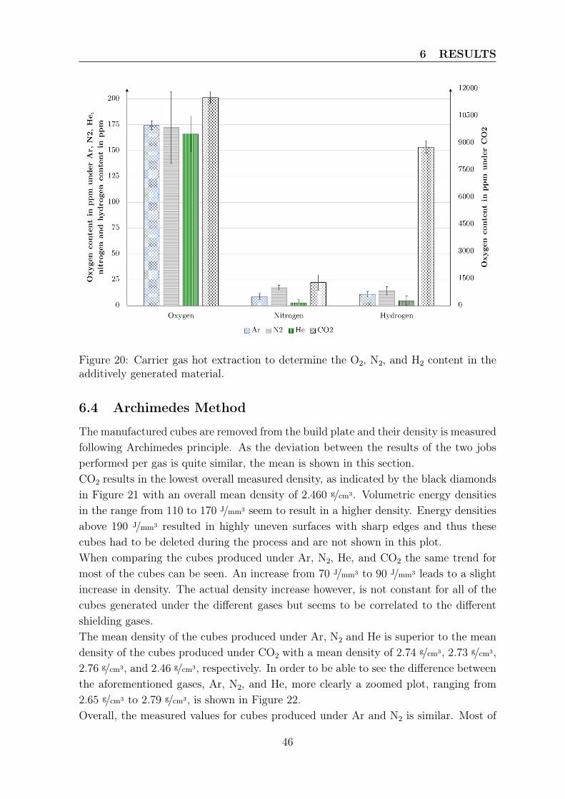
6 RESULTS
Figure 20: Carrier gas hot extraction to determine the O2, N2, and H2 content in theadditively generated material.
6.4 Archimedes Method
The manufactured cubes are removed from the build plate and their density is measuredfollowing Archimedes principle. As the deviation between the results of the two jobsperformed per gas is quite similar, the mean is shown in this section.CO2 results in the lowest overall measured density, as indicated by the black diamondsin Figure 21 with an overall mean density of 2.460 g/cm3. Volumetric energy densitiesin the range from 110 to 170 J/mm3 seem to result in a higher density. Energy densitiesabove 190 J/mm3 resulted in highly uneven surfaces with sharp edges and thus thesecubes had to be deleted during the process and are not shown in this plot.When comparing the cubes produced under Ar, N2, He, and CO2 the same trend formost of the cubes can be seen. An increase from 70 J/mm3 to 90 J/mm3 leads to a slightincrease in density. The actual density increase however, is not constant for all of thecubes generated under the different gases but seems to be correlated to the differentshielding gases.The mean density of the cubes produced under Ar, N2 and He is superior to the meandensity of the cubes produced under CO2 with a mean density of 2.74 g/cm3, 2.73 g/cm3,2.76 g/cm3, and 2.46 g/cm3, respectively. In order to be able to see the difference betweenthe aforementioned gases, Ar, N2, and He, more clearly a zoomed plot, ranging from2.65 g/cm3 to 2.79 g/cm3, is shown in Figure 22.Overall, the measured values for cubes produced under Ar and N2 is similar. Most of
46
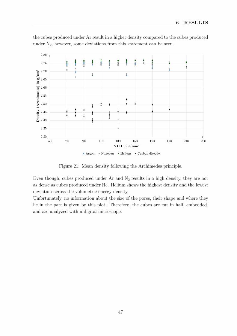
6 RESULTS
the cubes produced under Ar result in a higher density compared to the cubes producedunder N2, however, some deviations from this statement can be seen.
Figure 21: Mean density following the Archimedes principle.
Even though, cubes produced under Ar and N2 results in a high density, they are notas dense as cubes produced under He. Helium shows the highest density and the lowestdeviation across the volumetric energy density.Unfortunately, no information about the size of the pores, their shape and where theylie in the part is given by this plot. Therefore, the cubes are cut in half, embedded,and are analyzed with a digital microscope.
47
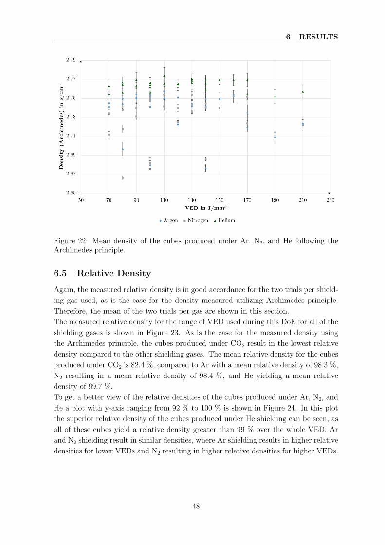
6 RESULTS
Figure 22: Mean density of the cubes produced under Ar, N2, and He following theArchimedes principle.
6.5 Relative Density
Again, the measured relative density is in good accordance for the two trials per shield-ing gas used, as is the case for the density measured utilizing Archimedes principle.Therefore, the mean of the two trials per gas are shown in this section.The measured relative density for the range of VED used during this DoE for all of theshielding gases is shown in Figure 23. As is the case for the measured density usingthe Archimedes principle, the cubes produced under CO2 result in the lowest relativedensity compared to the other shielding gases. The mean relative density for the cubesproduced under CO2 is 82.4 %, compared to Ar with a mean relative density of 98.3 %,N2 resulting in a mean relative density of 98.4 %, and He yielding a mean relativedensity of 99.7 %.To get a better view of the relative densities of the cubes produced under Ar, N2, andHe a plot with y-axis ranging from 92 % to 100 % is shown in Figure 24. In this plotthe superior relative density of the cubes produced under He shielding can be seen, asall of these cubes yield a relative density greater than 99 % over the whole VED. Arand N2 shielding result in similar densities, where Ar shielding results in higher relativedensities for lower VEDs and N2 resulting in higher relative densities for higher VEDs.
48
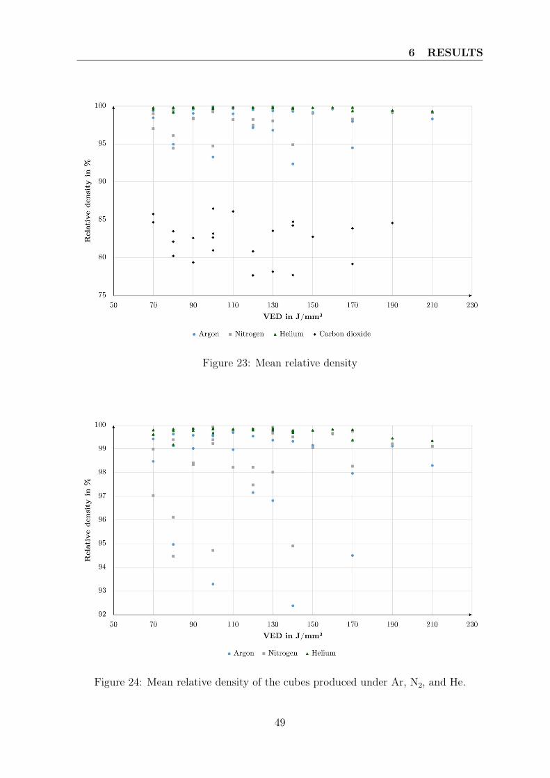
6 RESULTS
Figure 23: Mean relative density
Figure 24: Mean relative density of the cubes produced under Ar, N2, and He.
49
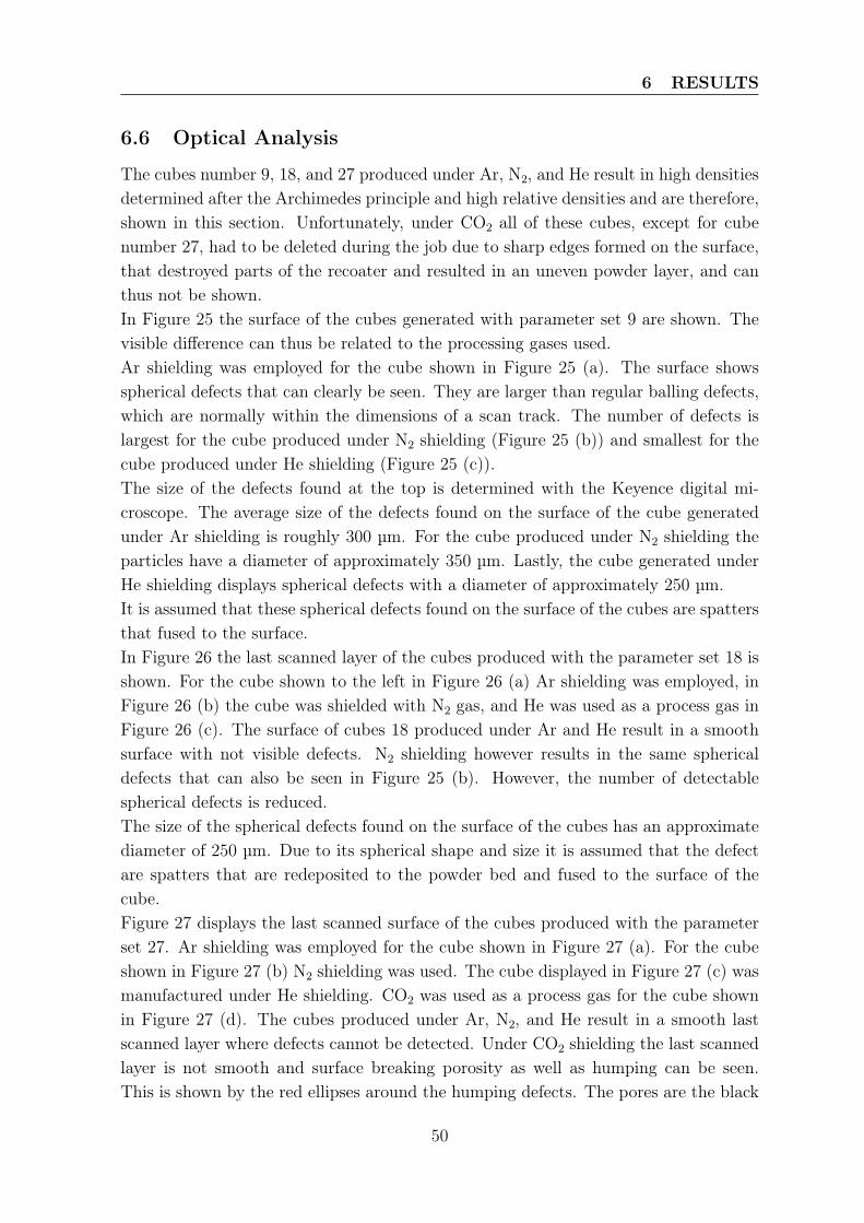
6 RESULTS
6.6 Optical Analysis
The cubes number 9, 18, and 27 produced under Ar, N2, and He result in high densitiesdetermined after the Archimedes principle and high relative densities and are therefore,shown in this section. Unfortunately, under CO2 all of these cubes, except for cubenumber 27, had to be deleted during the job due to sharp edges formed on the surface,that destroyed parts of the recoater and resulted in an uneven powder layer, and canthus not be shown.In Figure 25 the surface of the cubes generated with parameter set 9 are shown. Thevisible difference can thus be related to the processing gases used.Ar shielding was employed for the cube shown in Figure 25 (a). The surface showsspherical defects that can clearly be seen. They are larger than regular balling defects,which are normally within the dimensions of a scan track. The number of defects islargest for the cube produced under N2 shielding (Figure 25 (b)) and smallest for thecube produced under He shielding (Figure 25 (c)).The size of the defects found at the top is determined with the Keyence digital mi-croscope. The average size of the defects found on the surface of the cube generatedunder Ar shielding is roughly 300 µm. For the cube produced under N2 shielding theparticles have a diameter of approximately 350 µm. Lastly, the cube generated underHe shielding displays spherical defects with a diameter of approximately 250 µm.It is assumed that these spherical defects found on the surface of the cubes are spattersthat fused to the surface.In Figure 26 the last scanned layer of the cubes produced with the parameter set 18 isshown. For the cube shown to the left in Figure 26 (a) Ar shielding was employed, inFigure 26 (b) the cube was shielded with N2 gas, and He was used as a process gas inFigure 26 (c). The surface of cubes 18 produced under Ar and He result in a smoothsurface with not visible defects. N2 shielding however results in the same sphericaldefects that can also be seen in Figure 25 (b). However, the number of detectablespherical defects is reduced.The size of the spherical defects found on the surface of the cubes has an approximatediameter of 250 µm. Due to its spherical shape and size it is assumed that the defectare spatters that are redeposited to the powder bed and fused to the surface of thecube.Figure 27 displays the last scanned surface of the cubes produced with the parameterset 27. Ar shielding was employed for the cube shown in Figure 27 (a). For the cubeshown in Figure 27 (b) N2 shielding was used. The cube displayed in Figure 27 (c) wasmanufactured under He shielding. CO2 was used as a process gas for the cube shownin Figure 27 (d). The cubes produced under Ar, N2, and He result in a smooth lastscanned layer where defects cannot be detected. Under CO2 shielding the last scannedlayer is not smooth and surface breaking porosity as well as humping can be seen.This is shown by the red ellipses around the humping defects. The pores are the black
50
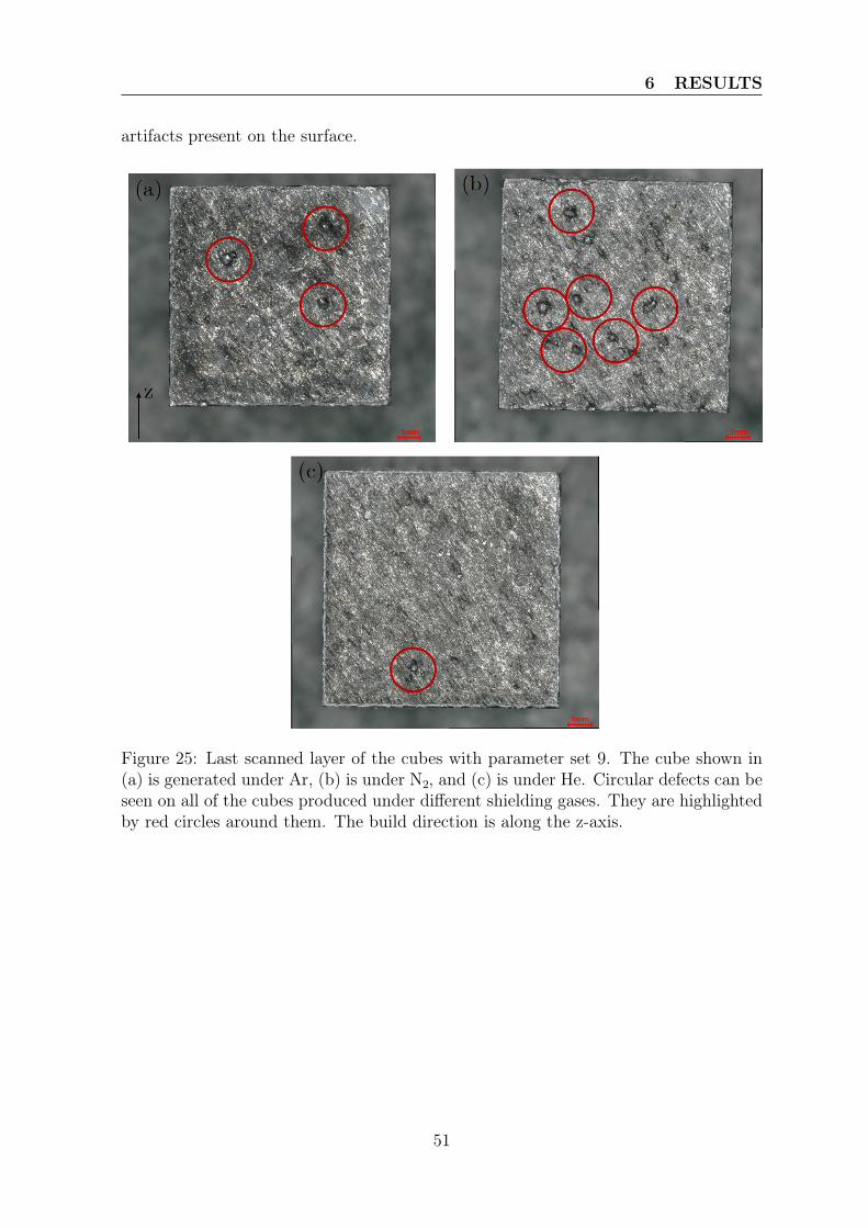
6 RESULTS
artifacts present on the surface.
Figure 25: Last scanned layer of the cubes with parameter set 9. The cube shown in(a) is generated under Ar, (b) is under N2, and (c) is under He. Circular defects can beseen on all of the cubes produced under different shielding gases. They are highlightedby red circles around them. The build direction is along the z-axis.
51
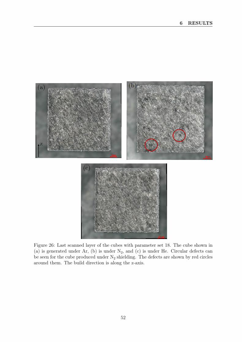
6 RESULTS
Figure 26: Last scanned layer of the cubes with parameter set 18. The cube shown in(a) is generated under Ar, (b) is under N2, and (c) is under He. Circular defects canbe seen for the cube produced under N2 shielding. The defects are shown by red circlesaround them. The build direction is along the z-axis.
52
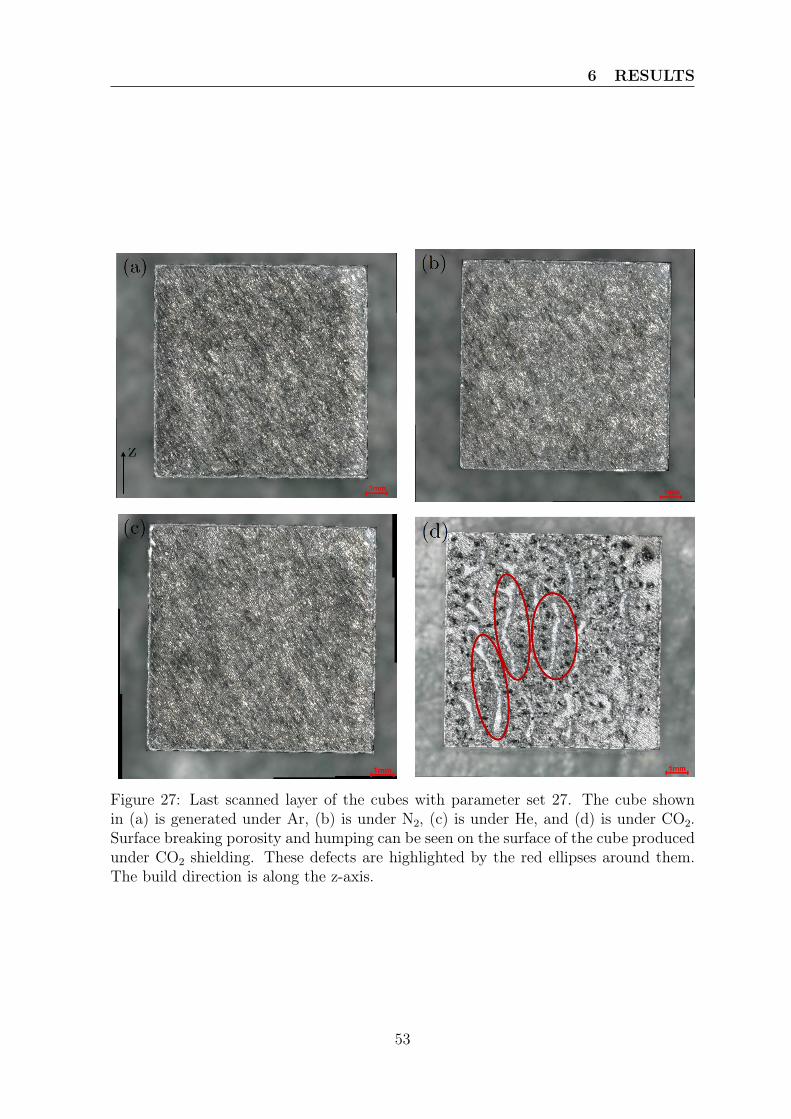
6 RESULTS
Figure 27: Last scanned layer of the cubes with parameter set 27. The cube shownin (a) is generated under Ar, (b) is under N2, (c) is under He, and (d) is under CO2.Surface breaking porosity and humping can be seen on the surface of the cube producedunder CO2 shielding. These defects are highlighted by the red ellipses around them.The build direction is along the z-axis.
53
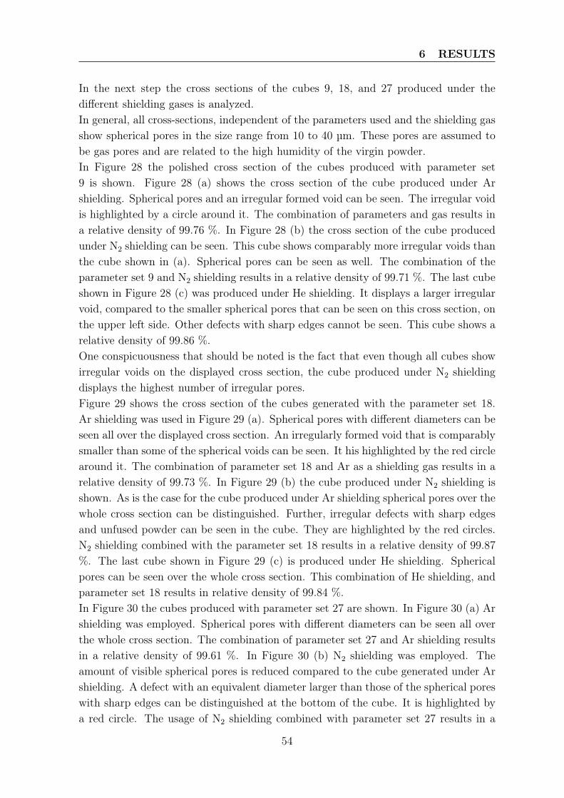
6 RESULTS
In the next step the cross sections of the cubes 9, 18, and 27 produced under thedifferent shielding gases is analyzed.In general, all cross-sections, independent of the parameters used and the shielding gasshow spherical pores in the size range from 10 to 40 µm. These pores are assumed tobe gas pores and are related to the high humidity of the virgin powder.In Figure 28 the polished cross section of the cubes produced with parameter set9 is shown. Figure 28 (a) shows the cross section of the cube produced under Arshielding. Spherical pores and an irregular formed void can be seen. The irregular voidis highlighted by a circle around it. The combination of parameters and gas results ina relative density of 99.76 %. In Figure 28 (b) the cross section of the cube producedunder N2 shielding can be seen. This cube shows comparably more irregular voids thanthe cube shown in (a). Spherical pores can be seen as well. The combination of theparameter set 9 and N2 shielding results in a relative density of 99.71 %. The last cubeshown in Figure 28 (c) was produced under He shielding. It displays a larger irregularvoid, compared to the smaller spherical pores that can be seen on this cross section, onthe upper left side. Other defects with sharp edges cannot be seen. This cube shows arelative density of 99.86 %.One conspicuousness that should be noted is the fact that even though all cubes showirregular voids on the displayed cross section, the cube produced under N2 shieldingdisplays the highest number of irregular pores.Figure 29 shows the cross section of the cubes generated with the parameter set 18.Ar shielding was used in Figure 29 (a). Spherical pores with different diameters can beseen all over the displayed cross section. An irregularly formed void that is comparablysmaller than some of the spherical voids can be seen. It his highlighted by the red circlearound it. The combination of parameter set 18 and Ar as a shielding gas results in arelative density of 99.73 %. In Figure 29 (b) the cube produced under N2 shielding isshown. As is the case for the cube produced under Ar shielding spherical pores over thewhole cross section can be distinguished. Further, irregular defects with sharp edgesand unfused powder can be seen in the cube. They are highlighted by the red circles.N2 shielding combined with the parameter set 18 results in a relative density of 99.87%. The last cube shown in Figure 29 (c) is produced under He shielding. Sphericalpores can be seen over the whole cross section. This combination of He shielding, andparameter set 18 results in relative density of 99.84 %.In Figure 30 the cubes produced with parameter set 27 are shown. In Figure 30 (a) Arshielding was employed. Spherical pores with different diameters can be seen all overthe whole cross section. The combination of parameter set 27 and Ar shielding resultsin a relative density of 99.61 %. In Figure 30 (b) N2 shielding was employed. Theamount of visible spherical pores is reduced compared to the cube generated under Arshielding. A defect with an equivalent diameter larger than those of the spherical poreswith sharp edges can be distinguished at the bottom of the cube. It is highlighted bya red circle. The usage of N2 shielding combined with parameter set 27 results in a
54
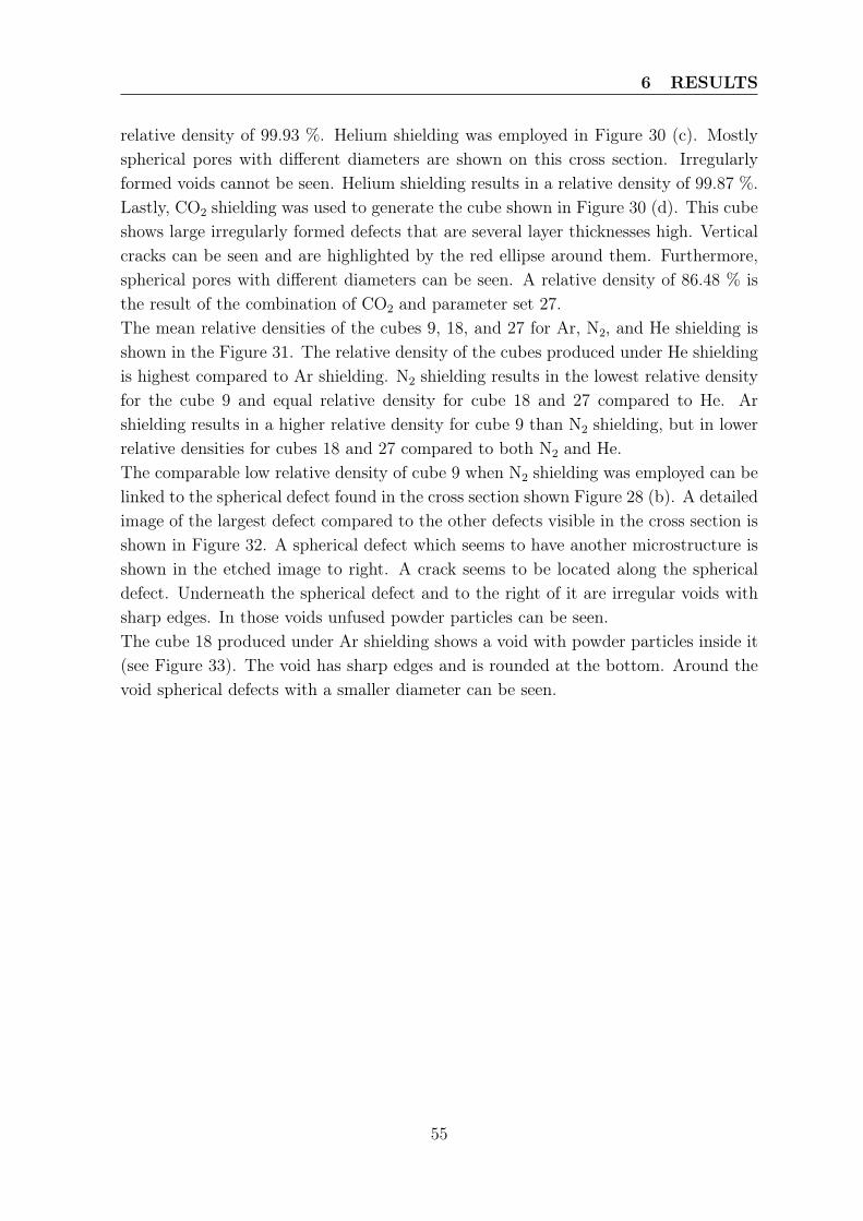
6 RESULTS
relative density of 99.93 %. Helium shielding was employed in Figure 30 (c). Mostlyspherical pores with different diameters are shown on this cross section. Irregularlyformed voids cannot be seen. Helium shielding results in a relative density of 99.87 %.Lastly, CO2 shielding was used to generate the cube shown in Figure 30 (d). This cubeshows large irregularly formed defects that are several layer thicknesses high. Verticalcracks can be seen and are highlighted by the red ellipse around them. Furthermore,spherical pores with different diameters can be seen. A relative density of 86.48 % isthe result of the combination of CO2 and parameter set 27.The mean relative densities of the cubes 9, 18, and 27 for Ar, N2, and He shielding isshown in the Figure 31. The relative density of the cubes produced under He shieldingis highest compared to Ar shielding. N2 shielding results in the lowest relative densityfor the cube 9 and equal relative density for cube 18 and 27 compared to He. Arshielding results in a higher relative density for cube 9 than N2 shielding, but in lowerrelative densities for cubes 18 and 27 compared to both N2 and He.The comparable low relative density of cube 9 when N2 shielding was employed can belinked to the spherical defect found in the cross section shown Figure 28 (b). A detailedimage of the largest defect compared to the other defects visible in the cross section isshown in Figure 32. A spherical defect which seems to have another microstructure isshown in the etched image to right. A crack seems to be located along the sphericaldefect. Underneath the spherical defect and to the right of it are irregular voids withsharp edges. In those voids unfused powder particles can be seen.The cube 18 produced under Ar shielding shows a void with powder particles inside it(see Figure 33). The void has sharp edges and is rounded at the bottom. Around thevoid spherical defects with a smaller diameter can be seen.
55
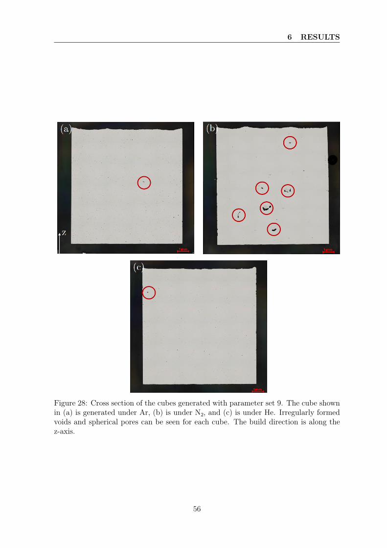
6 RESULTS
Figure 28: Cross section of the cubes generated with parameter set 9. The cube shownin (a) is generated under Ar, (b) is under N2, and (c) is under He. Irregularly formedvoids and spherical pores can be seen for each cube. The build direction is along thez-axis.
56
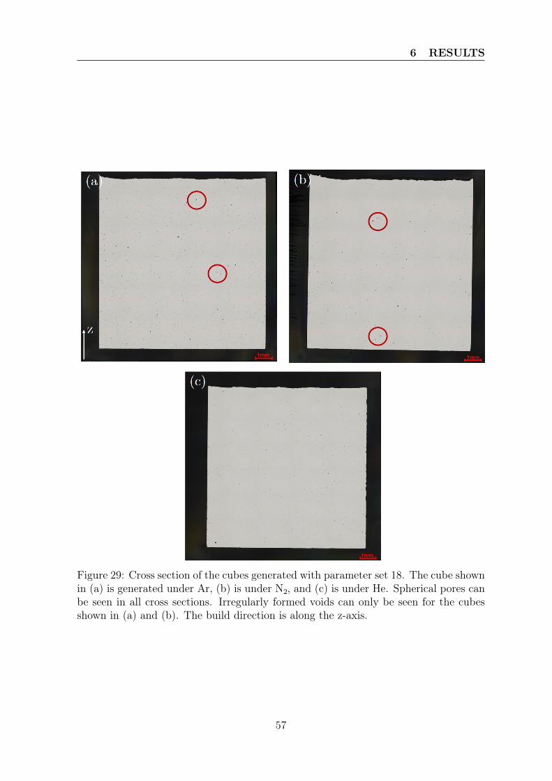
6 RESULTS
Figure 29: Cross section of the cubes generated with parameter set 18. The cube shownin (a) is generated under Ar, (b) is under N2, and (c) is under He. Spherical pores canbe seen in all cross sections. Irregularly formed voids can only be seen for the cubesshown in (a) and (b). The build direction is along the z-axis.
57
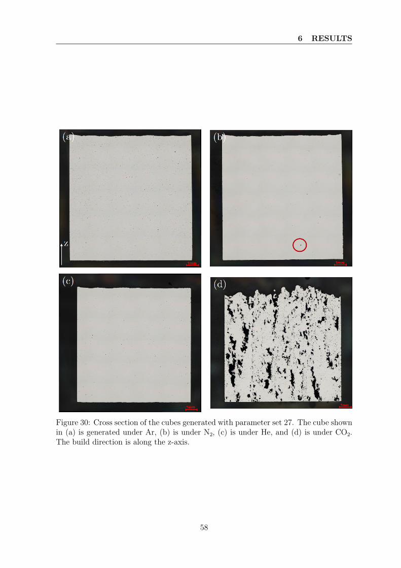
6 RESULTS
Figure 30: Cross section of the cubes generated with parameter set 27. The cube shownin (a) is generated under Ar, (b) is under N2, (c) is under He, and (d) is under CO2.The build direction is along the z-axis.
58
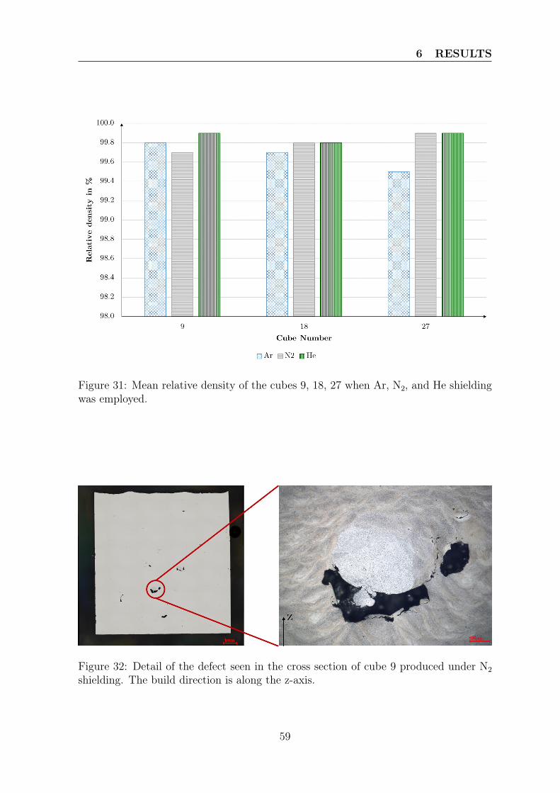
6 RESULTS
Figure 31: Mean relative density of the cubes 9, 18, 27 when Ar, N2, and He shieldingwas employed.
Figure 32: Detail of the defect seen in the cross section of cube 9 produced under N2shielding. The build direction is along the z-axis.
59
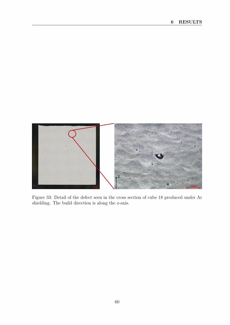
6 RESULTS
Figure 33: Detail of the defect seen in the cross section of cube 18 produced under Arshielding. The build direction is along the z-axis.
60
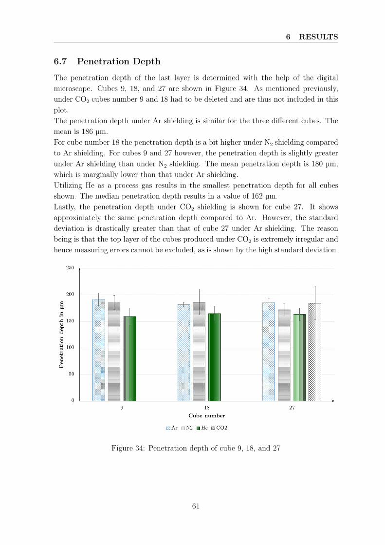
6 RESULTS
6.7 Penetration Depth
The penetration depth of the last layer is determined with the help of the digitalmicroscope. Cubes 9, 18, and 27 are shown in Figure 34. As mentioned previously,under CO2 cubes number 9 and 18 had to be deleted and are thus not included in thisplot.The penetration depth under Ar shielding is similar for the three different cubes. Themean is 186 µm.For cube number 18 the penetration depth is a bit higher under N2 shielding comparedto Ar shielding. For cubes 9 and 27 however, the penetration depth is slightly greaterunder Ar shielding than under N2 shielding. The mean penetration depth is 180 µm,which is marginally lower than that under Ar shielding.Utilizing He as a process gas results in the smallest penetration depth for all cubesshown. The median penetration depth results in a value of 162 µm.Lastly, the penetration depth under CO2 shielding is shown for cube 27. It showsapproximately the same penetration depth compared to Ar. However, the standarddeviation is drastically greater than that of cube 27 under Ar shielding. The reasonbeing is that the top layer of the cubes produced under CO2 is extremely irregular andhence measuring errors cannot be excluded, as is shown by the high standard deviation.
Figure 34: Penetration depth of cube 9, 18, and 27
61
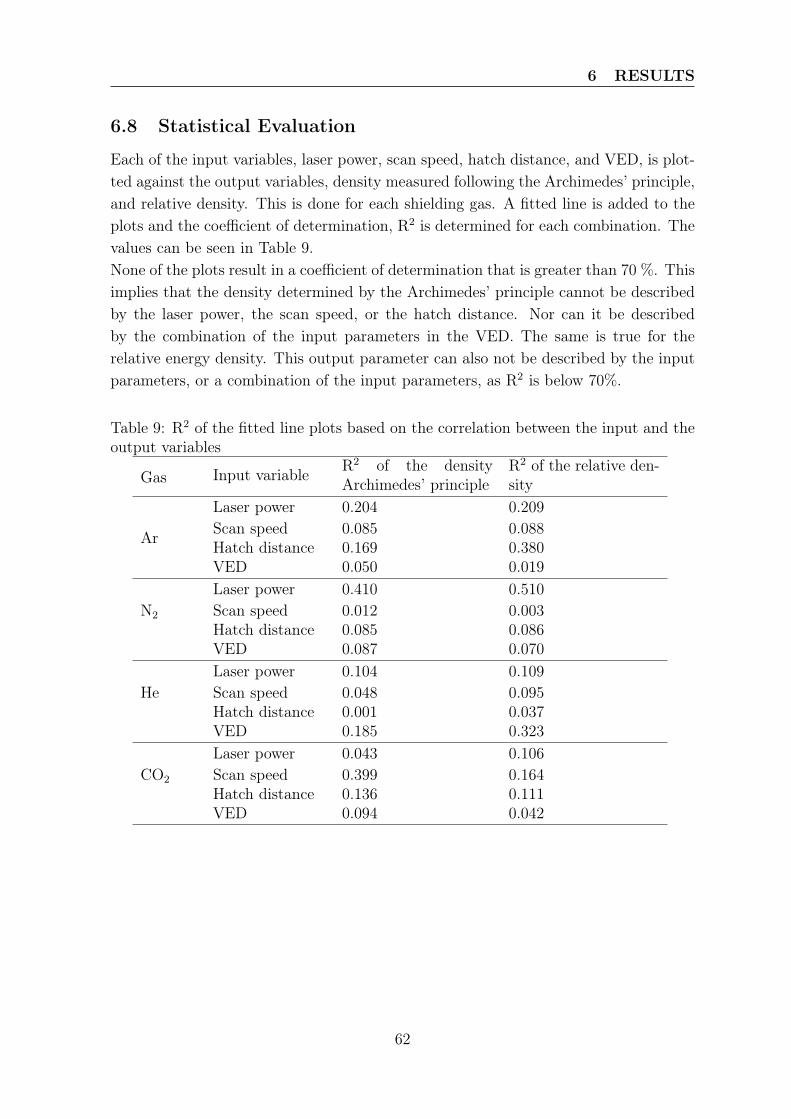
6 RESULTS
6.8 Statistical Evaluation
Each of the input variables, laser power, scan speed, hatch distance, and VED, is plot-ted against the output variables, density measured following the Archimedes’ principle,and relative density. This is done for each shielding gas. A fitted line is added to theplots and the coefficient of determination, R2 is determined for each combination. Thevalues can be seen in Table 9.None of the plots result in a coefficient of determination that is greater than 70 %. Thisimplies that the density determined by the Archimedes’ principle cannot be describedby the laser power, the scan speed, or the hatch distance. Nor can it be describedby the combination of the input parameters in the VED. The same is true for therelative energy density. This output parameter can also not be described by the inputparameters, or a combination of the input parameters, as R2 is below 70%.
Table 9: R2 of the fitted line plots based on the correlation between the input and theoutput variables
Gas Input variable R2 of the densityArchimedes’ principle
R2 of the relative den-sity
Ar
Laser power 0.204 0.209Scan speed 0.085 0.088Hatch distance 0.169 0.380VED 0.050 0.019
N2
Laser power 0.410 0.510Scan speed 0.012 0.003Hatch distance 0.085 0.086VED 0.087 0.070
HeLaser power 0.104 0.109Scan speed 0.048 0.095Hatch distance 0.001 0.037VED 0.185 0.323
CO2
Laser power 0.043 0.106Scan speed 0.399 0.164Hatch distance 0.136 0.111VED 0.094 0.042
62
7 DISCUSSION
7 Discussion
The formulated research questions are being connected to the results obtained fromthe study. They are answered in this section, and possible hypotheses are stated.In general, it should be noted, that all of the cubes show spherical pores with a diameterranging from 10 to 40 µm. It is believed that these pores are gas pores, that are theresult of the humidity of the virgin powder, as shown in Figure 17. Through the energysupplied by the laser, humidity on the surface of the powder particles is decomposedas shown by Equation 2. The surface of the melt pool is oxidized, and hydrogen isabsorbed by the melt pool. As soon as the liquid metal solidifies hydrogen pores areformed.The addition of Zr to the alloy successfully lowers the susceptibility to cracking. In thecubes produced under Ar and He shielding cracking was not seen. However, a crackunder N2 shielding can be distinguished. It should be mentioned that the additionof Zr should prevent hot cracking. The formed crack determined in the cross-sectionof cube 9 shown in Figure 32 under N2 shielding, seems to be a result of the spatterand not of the process itself, as the rest of the cross-section is crack free. Other cubesproduced under N2 shielding with different parameter do not show cracks on theircross-section. The usage of CO2 seems to result in cracks, however, it is believed thatthe formed cracks is the result of the shielding gas used, as the other gases result insamples without hot cracking being detectable.
7.1 Influence of the Process Gases on the Formation of Process-by-Products - RQ1
The interaction between the powder bed and the laser beam when different shieldinggases are used is shown in Figure 12.N2 and Ar shielding both result in a fairly similar interaction of the laser beam withthe powder bed. For both process gases particles above the powder bed are radiatedby the laser beam, and become incandescent. This is in accordance with the findingsof other researchers [8, 59], that suggest that Ar and N2 can both be used as a processgas during PBF-LB/M. As interaction above the powder bed can be seen, it is assumedthat a vapor jet is formed under Ar and N2 shielding. The formed jet entrains virginpowder particles from the powder bed and transports them to the laser beam wherethey interact with it. The strength of the formed vapor jet is not determined duringthis thesis.Ar has a higher density than N2 (see Table 4). This difference and the resulting forceapplied to the process-by-products above the powder bed through the presence of a gasflow can be seen in the different curvatures under Ar and N2 shielding, respectively.Under Ar shielding, the trajectory of the rays show a higher curvature compared to thetrajectory under N2 shielding. N2 shielding results in particles traveling higher before
63
7 DISCUSSION
they are transported away from the interaction zone by the gas flow. This is due tothe lower density of N2 compared to Ar.Under He shielding a smaller number of bright, light-emitting process-by-products canbe seen. The length of the rays is shorter, which is a result of the quick cooling ofthe incandescent spatters. Helium possesses the highest thermal conductivity and thehighest specific heat. Hence, its ability to transfer and hold heat is superior comparedto the other gases. Pauzon et al. [3] show that under He, and mixtures of Ar and Heshielding, the number of incandescent spatters and the length of the rays is reduced.Their findings are in accordance with the results of this study. They conclude thatdue to a lower temperature of the melt pool less Marangoni convection and lower recoilpressure are present in the melt pool. This reduces the number of droplets being ejectedfrom the melt pool. However, droplets that are ejected from the melt pool are cooledmuch more efficiently compared to droplets ejected under Ar, N2, or CO2 shielding.Therefore, the incandescent particles are only visible for a short distance compared tothe other shielding gases used and shown. It is suspected that a vapor jet forms as well,as particles become incandescent above the powder bed. Hence the formed vapor jettransports virgin powder to the laser beam where they are heated and become visible.Yet, the strength of the formed vapor jet is possibly reduced, as less interaction withthe laser beam above the powder bed can be seen.Under CO2 shielding the interaction between the laser beam and the powder bed ismore pronounced compared to the other shielding gases. The length of the rays islonger than those under Ar, N2, or He. Longer rays can either be the result of (1) ahigher temperature of the spatters, or (2) slower cooling through the process gas, or acombination of both. Regarding (1) the temperature of the incandescent spatters couldnot be determined. However, as CO2 is classified as an active gas, the assumption canbe made that the temperature of the melt pool and the spatters is higher, as oxygenaids burning and creates an exothermal reaction. The brighter color of the rays - moreyellow than under Ar, N2, and He - indicates a hotter process compared to the morereddish rays under the other gases. For (2), it is assumed that the length of the rayscan be the result of worse thermal properties associated with CO2. CO2 has the lowestability to transfer heat, compared to the other gases, see Table 4. Interactions betweenparticles and the laser beam above the powder bed can be seen, as well. This leadsto the conclusion, that CO2 shielding also results in the formation a vapor jet thatentrains particles from the powder bed. Again, the strength of the formed vapor jetcould not be determined. Lastly, the color of the rays under CO2 shielding is differentas mentioned above. This was also visible with the naked eye and is not suspected tobe an artifact of the white balance of the camera. The change from reddish rays tomore yellow in color can either be the result of less lithium being burnt or a hotterprocess. When lithium salts are burnt in a flame, the flame color turns red. Due tothe presence of oxygen in the shielding gas, the process is supplied with extra energyand could be hotter, leading to brighter particles, as stated previously.
64
7 DISCUSSION
The higher amount of process-by-products in the interaction zone under Ar, N2, andCO2 shielding can result in energy from the laser beam being lost during the interactionof the laser beam with process-by-products. Not enough energy is supplied to thepowder bed and the underlying layers, which can result in the formation of pores. Thehigher porosity values determined from the cubes generated under the aforementionedgases can be a direct result. Under He shielding less process-by-products are visible,resulting in a comparable higher relative and bulk density.
7.2 Influence of the Process Gases on the Characteristics ofProcess-by-Products - RQ2
The PSD of the generated spatters were analyzed with a Camsizer. The size classes ofthe spatter compared to the virgin powder is shown in Figure 15. The virgin powderas well as the spatters collected after the CO2 jobs, have a fairly similar fractional per-centile per size class, especially in the smaller size classes. This leads to the conclusionthat many of the particles collected near the gas outlet after the CO2 job was finished,are particles from the virgin powder bed entrained by the vapor jet and transportedto the chamber gas outlet. This hypothesis is reinforced by the shape of the process-by-products generated after each job. Their sphericity is shown in Table 8. The virginpowder, as well as the spatters collected after CO2 shielding was used both have asphericity greater than 75 %. Hence, this again leads to the assumption that the virginpowder particles are entrained by the vapor jet and land at the chamber gas outlet.On the other hand, the high sphericity of the spatters generated under CO2 shieldingcan also be the result of a hotter process and slower cooling rates. The cooling of theincandescent spatters is connected to the thermal conductivity of the process gas. CO2
has the lowest thermal conductivity and it is thus assumed that the liquid dropletshave more time to spherodize before they are solidified and are thus more rounded.It should be noted that the spatters produced under Ar and N2 shielding both resultin a sphericity of approximately 60 %. This is lower than the sphericity of the spattersproduced under CO2 shielding. However, both Ar and N2 can be associated with moresuperior thermal properties than CO2. The superior thermal properties shorten the so-lidification time of the droplets ejected from the melt pool, resulting in a less roundedparticle shape. When only the particle shape of the process-by-products is concernedboth gases can be used interchangeably as a shielding gas during PBF-LB/M. Yet, thepart quality is different under the two process gases, as previously mentioned. Thelowest sphericity (53 %) can be found in the spatters generated under He shielding.The thermal conductivity of He is superior compared to the other gases. Helium holdsthe highest thermal convection and specific heat capacity, implying that its ability totransfer heat away from the liquid droplet and hold the heat is superior compared tothe other gases. Hence, its solidification time is shorter, and the shape of the dropletcould be frozen in place, before it fully spherodizes.
65
7 DISCUSSION
Process-by-products collected at the chamber gas outlet that are larger than the D90of the virgin powder are assumed to be droplets ejected from the melt pool. This isreinforced by the work done by Ly et al. [2], who simulated the PBF-LB/M process,and found that droplets that are ejected from the melt pool have a larger diameterthan powder particles entrained by the vapor jet.The percentiles for each size class under Ar and N2 shielding is very similar (see Figure15). This implies that (1) the interaction of the laser with the powder bed and theresulting melt pool has a similar stability under Ar and N2 shielding, and (2) the result-ing vapor jet has a similar strength. For (1) the droplets being ejected from the meltpool have a larger diameter than the entrained particles from the powder bed. Thepercentiles for the larger size classes (> D90 of the virgin powder) are almost identical.To discuss (2), the percentiles for the smaller particles (< D90 of the virgin powder)determined are very similar as well. It is hypothesized that the resulting vapor jet hasa similar strength and entrains equal sized powder particles independently of Ar or N2
shielding.The usage of He results in a more narrow PSD. The D10 under He shielding is greatestcompared to the other gases. Yet, D90 of the spatters under He shielding is smallerthan D90 under Ar or N2 shielding. It can be suggested that a lower number of particlesare entrained by the vapor jet and are transported away from the powder bed, thusresulting in a higher D10 compared to the other gases. D90 is smaller than under Arand N2 shielding, which can be the result of less process-by-products being ejected fromthe melt pool, which implies that the melt pool under He shielding is stabler resultingin a lower number of droplets. Pauzon et al. [3] hypothesize that helium results in amore efficient cooling of the melt pool, which delays the onset of vaporization and thusreduced the recoil pressure and Marangoni convection. Hence, the found results are inaccordance with recent results stated by Pauzon et al. [3].
7.3 Influence of the Shielding Gas on the Finished Part - RQ3
7.3.1 Defect Formation through Insufficient Removal ofProcess-by-Products
The surface of the parts produced with parameter set 9 (see Figure 25) all show spher-ical defects. Under Ar shielding a couple of defects - less than five - with a meandiameter of approximately 300 µm can be detected. Using N2 as a processing gas, re-sults in a higher number of defects - greater than five - with a mean diameter of roughly350 µm. Helium on the other hand results in a lower number of defects compared toAr and N2 with the smallest mean diameter of about 250 µm.The number and size of the defects found on the last scanned layer of cube 9 is differentfor the process gases. The defects are more pronounced for the cubes produced underAr and N2 shielding, and less visible, i.e., smaller, and less, for the cube produced
66
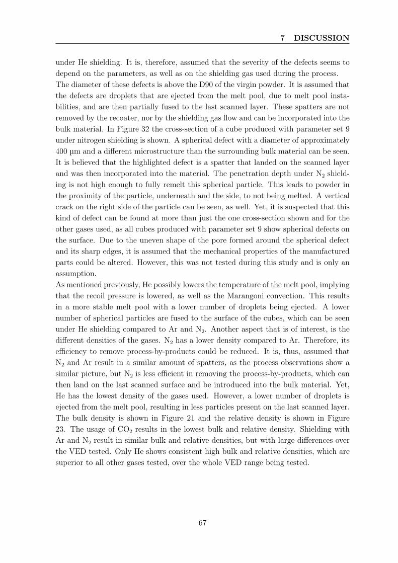
7 DISCUSSION
under He shielding. It is, therefore, assumed that the severity of the defects seems todepend on the parameters, as well as on the shielding gas used during the process.The diameter of these defects is above the D90 of the virgin powder. It is assumed thatthe defects are droplets that are ejected from the melt pool, due to melt pool insta-bilities, and are then partially fused to the last scanned layer. These spatters are notremoved by the recoater, nor by the shielding gas flow and can be incorporated into thebulk material. In Figure 32 the cross-section of a cube produced with parameter set 9under nitrogen shielding is shown. A spherical defect with a diameter of approximately400 µm and a different microstructure than the surrounding bulk material can be seen.It is believed that the highlighted defect is a spatter that landed on the scanned layerand was then incorporated into the material. The penetration depth under N2 shield-ing is not high enough to fully remelt this spherical particle. This leads to powder inthe proximity of the particle, underneath and the side, to not being melted. A verticalcrack on the right side of the particle can be seen, as well. Yet, it is suspected that thiskind of defect can be found at more than just the one cross-section shown and for theother gases used, as all cubes produced with parameter set 9 show spherical defects onthe surface. Due to the uneven shape of the pore formed around the spherical defectand its sharp edges, it is assumed that the mechanical properties of the manufacturedparts could be altered. However, this was not tested during this study and is only anassumption.As mentioned previously, He possibly lowers the temperature of the melt pool, implyingthat the recoil pressure is lowered, as well as the Marangoni convection. This resultsin a more stable melt pool with a lower number of droplets being ejected. A lowernumber of spherical particles are fused to the surface of the cubes, which can be seenunder He shielding compared to Ar and N2. Another aspect that is of interest, is thedifferent densities of the gases. N2 has a lower density compared to Ar. Therefore, itsefficiency to remove process-by-products could be reduced. It is, thus, assumed thatN2 and Ar result in a similar amount of spatters, as the process observations show asimilar picture, but N2 is less efficient in removing the process-by-products, which canthen land on the last scanned surface and be introduced into the bulk material. Yet,He has the lowest density of the gases used. However, a lower number of droplets isejected from the melt pool, resulting in less particles present on the last scanned layer.The bulk density is shown in Figure 21 and the relative density is shown in Figure23. The usage of CO2 results in the lowest bulk and relative density. Shielding withAr and N2 result in similar bulk and relative densities, but with large differences overthe VED tested. Only He shows consistent high bulk and relative densities, which aresuperior to all other gases tested, over the whole VED range being tested.
67
7 DISCUSSION
7.3.2 Change in Chemistry of the Printed Component
One aspect that is of importance during this study is that the shielding gas usedshould not interact with the powdered material, nor with the liquid melt. Any form ofincorporation of the process gas into the printed material is unwanted and should beprevented. A change in chemistry of the generated material can be the direct result.This can then alter the mechanical properties of the produced part.The O2, N2, and H2 content in the samples and the spatters can be detected throughcarrier gas hot extraction. The N2 content detected in the sample and the spatters afterthe jobs with Ar shielding are performed, apply as a reference. N2 can be picked upthrough the formation of nitrides. There are two possible nitrides that can be formedbased on the constituents of the alloy. The first one is AlN, and the second one isLi3N. As stated by Wang et al. [59], to form AlN the temperature needs to be elevatedover a long period of time, as is the case during sintering. The time needed to formAlN is longer than the short time when the laser interacts with the powder typicallyfound in additive manufacturing. Hence, the formation of AlN is not plausible. Li3Non the other hand forms more readily and is a stable compound at ambient conditionsas shown by Brauer [62].When comparing the N2 content in the spatters shown in Figure 19 it can be seen thatN2 shielding results in the highest N2 content. For the manufactured cylinders, seeFigure 20, the N2 content in the cylinders produced under N2 shielding is approximately9 ppm greater than the N2 content in the cylinders produced under Ar shielding. Thisincrease can either be through an error during the analysis, or by the formation ofnitrides as discussed previously. Yet, the increase is present and it should be furtheranalyzed where it came from. The reason why CO2 shielding results in a higher N2
content in the samples can, as of now, not be explained and needs further research.
7.3.3 Likelihood of Oxidation of the Surface of the Liquid Melt
The used alloy has different constituents that have different melting temperatures.In order to fully melt the powdered material, the energy supplied by the laser mustbe high enough to surpass the melting point of the element with the highest meltingtemperature. For this alloy the element with the highest melting point is Zr, which hasa melting point of 1852 °C. Therefore, the laser energy needs to be sufficient to achievehigh enough temperatures in the powder bed. Li et al. [32] stated that temperaturesencountered during PBF-LB/M can be greater than 1800 °C.The Gibbs free energy, ∆G◦, of the diffusion-controlled oxidation process is dependenton the temperature. ∆G◦ can be determined with the help of the Ellingham diagram,see Figure 3, The elements present in the alloy that can be oxidized are Al, Cu, andMg. The more negative ∆G◦ of each of the reaction of the elements with oxygen at agiven temperature is, the higher the likelihood that this reaction takes place.The ∆G◦
Cu at 1600 °C is highest with a value of approximately -100 kJ/mol. The reaction
68
7 DISCUSSION
of Mg withO2 at 1600 °C results in a ∆G◦Mg of -700 kJ/mol. The same reaction but with
Al at 1600 °C results in a ∆G◦Al of -714 kJ/mol.
Both reactions only need the presence of very little oxygen present in the chamber.Due to leakages, impurities in the shielding gas and residual oxygen present in thechamber, enough oxygen is present to react at the given temperatures.The reaction of Al with O2 to form Al2O3 results in a lower ∆G◦ and is, thus, morelikely to happen.It is hypothesized that the choice of process gas is of extreme importance, as thetemperature plays an important part in the diffusion driven process of oxidation. Thequicker the material is cooled and solidified, the thinner is the formed oxide layer. Thesuperior cooling capacities of He result in a quicker cooling of the incandescent spatters.This reduces the thickness of the formed oxide layer. The spatters generated under Heshielding result in the lowest oxygen content compared to the spatters generated underAr, N2, and CO2 shielding see Figure 19.
7.3.4 Implication of the Presence of an Oxide Layer
As discussed in the previous section, aluminum readily reacts even with low oxygenconcentrations present in the chamber. The usage of CO2 as a shielding gas, alreadysupplies a significant amount of O2, which promotes oxidation of the liquid metal.Small quantities of CO2 can be decomposed to pure C and O2 which supplies a sourcefor the formation of Al2O3. Yet, the direct reaction of CO2 with Al as shown by theEquation 7 and 8 can also take place.In Figure 20 the oxygen content of the printed cylinders using the different shieldinggases is shown. It should be noted that the usage of CO2 results in the highest oxygencontent measured in the cylinders which is approximately 11500 ppm. It is assumedthat the measured oxygen is present in the form of an oxide on the surface of the cylinderand between the generated layers. Lu et al. [65] state that the thickness of the oxidelayer increases as the temperature of the process increases. Through the presence ofoxygen during the job it is assumed that the temperature is higher compared to thetemperature when the other gases are used. A thicker oxide layer on each scannedlayer can thus be expected, and a higher oxygen content present in the sample can beseen in the mentioned figure.More energy is needed to destroy the thicker oxide layers present on the scanned surface.Das [44] claims that the presence of an oxide layer that is not destroyed impedeswetting and results in insufficient bonding between the layers. It is believed thatballing of the deposited liquid aluminum is a result and the surface of the scannedlayer is deteriorated. The last scanned layer of the cube 27 produced under CO2
shielding is shown in Figure 27 (d). An uneven surface with differences in height of upto 400 µm, measured with a digital microscope, can be seen. Further, surface breakingporosity can be detected, as well.
69
7 DISCUSSION
Boukha et al. [55] demonstrate that the Marangoni convection pattern depends on thesurface temperature gradient. Through the presence of oxygen in the melt pool, whichis a surface-active element, the Marangoni flow is changed from an outward flow to aninward flow. Tang et al. [40] simulate outward Marangoni flow, which is present fora negative surface tension gradient, and inward Marangoni flow, caused by a positivesurface tension. The inward Marangoni flow results in a convex surface of the scannedand solidified track and a deeper penetration. The penetration depth of the cube 27produced under CO2 shielding was difficult to determine, as the top layer is uneven.The penetration depth for the cube 27 under the different shielding gases used canbe seen in Figure 34. However, the measured melt pool depths indicate, to a certaindegree, an as deep penetration as under Ar shielding, or even deeper due to the highdeviation of the measurements.The uneven surface and the high porosity detected in the cube 27 generated under CO2
shielding could be due to the combination of the presence of a thick oxide layer whichis difficult to destroy, the humping phenomenon due to the changed Marangoni flow,and probably a less stable process.
70
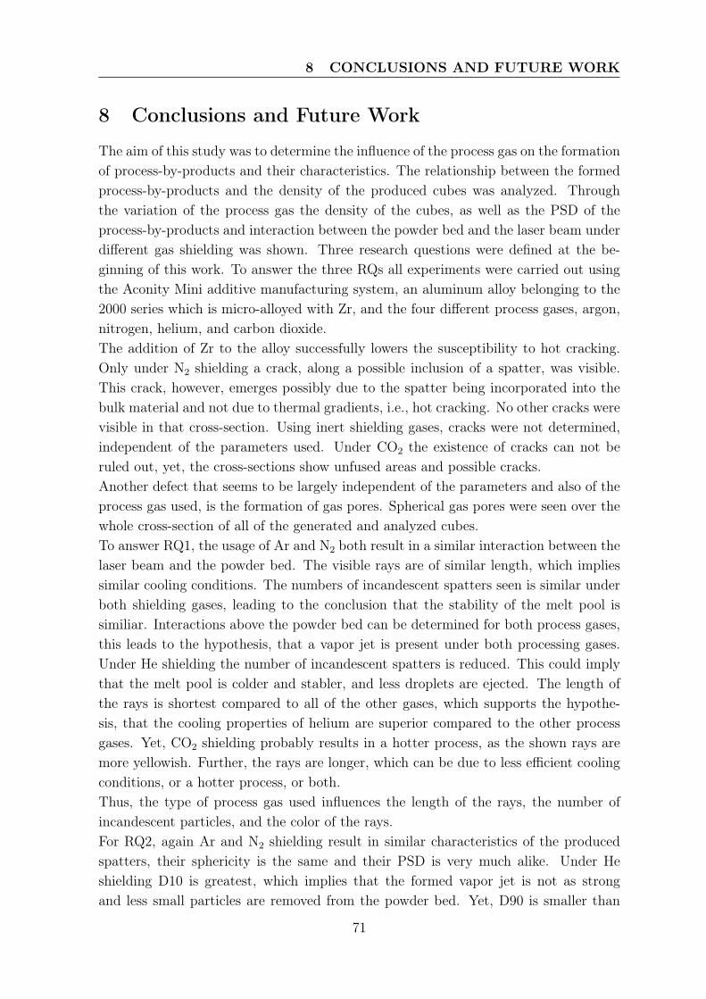
8 CONCLUSIONS AND FUTURE WORK
8 Conclusions and Future Work
The aim of this study was to determine the influence of the process gas on the formationof process-by-products and their characteristics. The relationship between the formedprocess-by-products and the density of the produced cubes was analyzed. Throughthe variation of the process gas the density of the cubes, as well as the PSD of theprocess-by-products and interaction between the powder bed and the laser beam underdifferent gas shielding was shown. Three research questions were defined at the be-ginning of this work. To answer the three RQs all experiments were carried out usingthe Aconity Mini additive manufacturing system, an aluminum alloy belonging to the2000 series which is micro-alloyed with Zr, and the four different process gases, argon,nitrogen, helium, and carbon dioxide.The addition of Zr to the alloy successfully lowers the susceptibility to hot cracking.Only under N2 shielding a crack, along a possible inclusion of a spatter, was visible.This crack, however, emerges possibly due to the spatter being incorporated into thebulk material and not due to thermal gradients, i.e., hot cracking. No other cracks werevisible in that cross-section. Using inert shielding gases, cracks were not determined,independent of the parameters used. Under CO2 the existence of cracks can not beruled out, yet, the cross-sections show unfused areas and possible cracks.Another defect that seems to be largely independent of the parameters and also of theprocess gas used, is the formation of gas pores. Spherical gas pores were seen over thewhole cross-section of all of the generated and analyzed cubes.To answer RQ1, the usage of Ar and N2 both result in a similar interaction between thelaser beam and the powder bed. The visible rays are of similar length, which impliessimilar cooling conditions. The numbers of incandescent spatters seen is similar underboth shielding gases, leading to the conclusion that the stability of the melt pool issimiliar. Interactions above the powder bed can be determined for both process gases,this leads to the hypothesis, that a vapor jet is present under both processing gases.Under He shielding the number of incandescent spatters is reduced. This could implythat the melt pool is colder and stabler, and less droplets are ejected. The length ofthe rays is shortest compared to all of the other gases, which supports the hypothe-sis, that the cooling properties of helium are superior compared to the other processgases. Yet, CO2 shielding probably results in a hotter process, as the shown rays aremore yellowish. Further, the rays are longer, which can be due to less efficient coolingconditions, or a hotter process, or both.Thus, the type of process gas used influences the length of the rays, the number ofincandescent particles, and the color of the rays.For RQ2, again Ar and N2 shielding result in similar characteristics of the producedspatters, their sphericity is the same and their PSD is very much alike. Under Heshielding D10 is greatest, which implies that the formed vapor jet is not as strongand less small particles are removed from the powder bed. Yet, D90 is smaller than
71
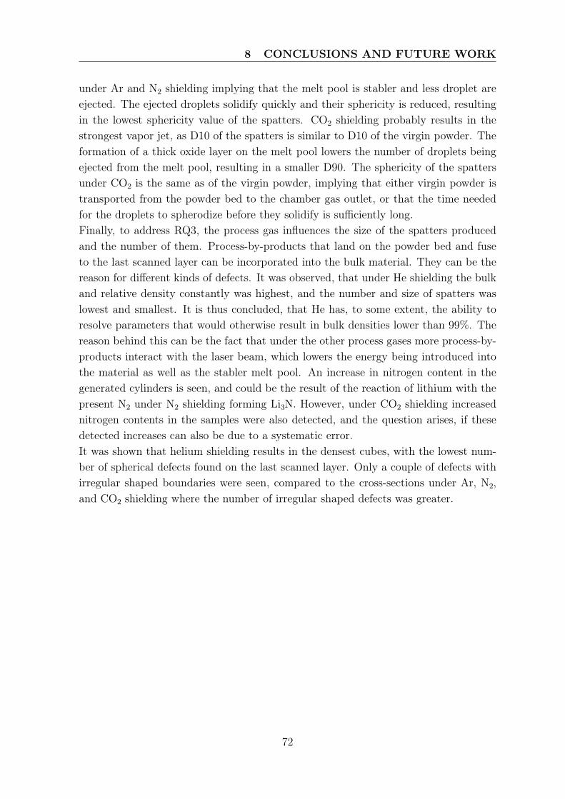
8 CONCLUSIONS AND FUTURE WORK
under Ar and N2 shielding implying that the melt pool is stabler and less droplet areejected. The ejected droplets solidify quickly and their sphericity is reduced, resultingin the lowest sphericity value of the spatters. CO2 shielding probably results in thestrongest vapor jet, as D10 of the spatters is similar to D10 of the virgin powder. Theformation of a thick oxide layer on the melt pool lowers the number of droplets beingejected from the melt pool, resulting in a smaller D90. The sphericity of the spattersunder CO2 is the same as of the virgin powder, implying that either virgin powder istransported from the powder bed to the chamber gas outlet, or that the time neededfor the droplets to spherodize before they solidify is sufficiently long.Finally, to address RQ3, the process gas influences the size of the spatters producedand the number of them. Process-by-products that land on the powder bed and fuseto the last scanned layer can be incorporated into the bulk material. They can be thereason for different kinds of defects. It was observed, that under He shielding the bulkand relative density constantly was highest, and the number and size of spatters waslowest and smallest. It is thus concluded, that He has, to some extent, the ability toresolve parameters that would otherwise result in bulk densities lower than 99%. Thereason behind this can be the fact that under the other process gases more process-by-products interact with the laser beam, which lowers the energy being introduced intothe material as well as the stabler melt pool. An increase in nitrogen content in thegenerated cylinders is seen, and could be the result of the reaction of lithium with thepresent N2 under N2 shielding forming Li3N. However, under CO2 shielding increasednitrogen contents in the samples were also detected, and the question arises, if thesedetected increases can also be due to a systematic error.It was shown that helium shielding results in the densest cubes, with the lowest num-ber of spherical defects found on the last scanned layer. Only a couple of defects withirregular shaped boundaries were seen, compared to the cross-sections under Ar, N2,and CO2 shielding where the number of irregular shaped defects was greater.
72
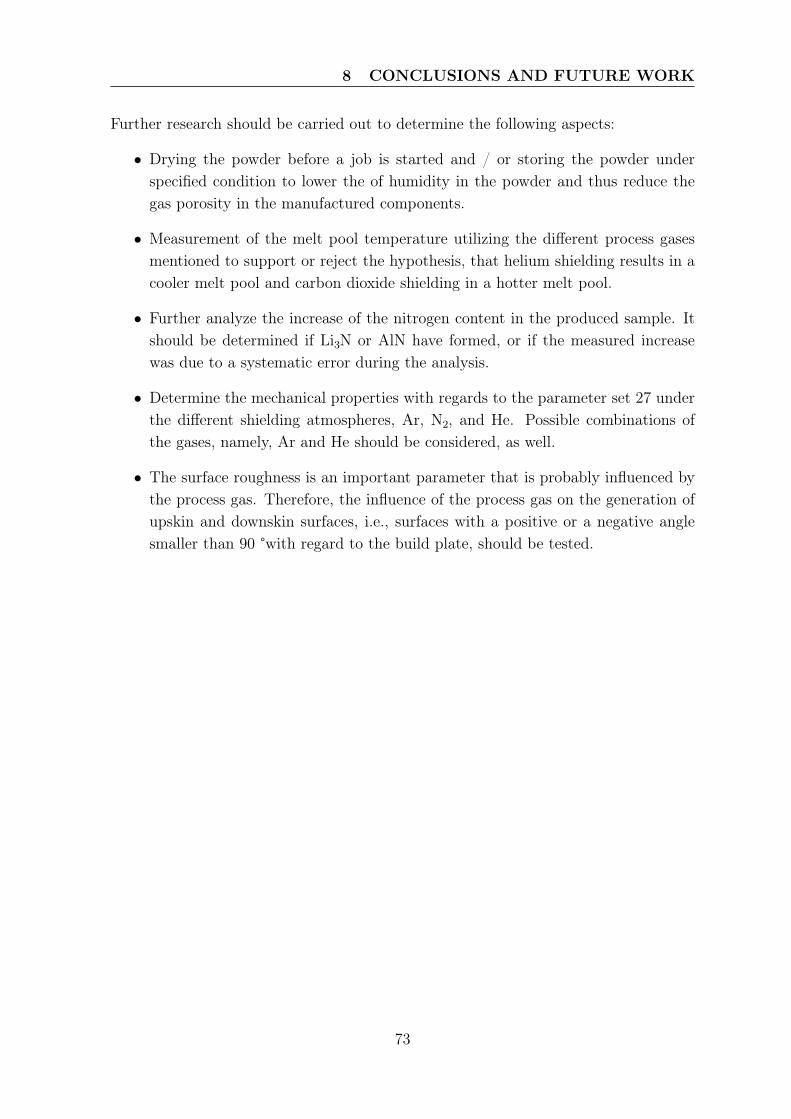
8 CONCLUSIONS AND FUTURE WORK
Further research should be carried out to determine the following aspects:
• Drying the powder before a job is started and / or storing the powder underspecified condition to lower the of humidity in the powder and thus reduce thegas porosity in the manufactured components.
• Measurement of the melt pool temperature utilizing the different process gasesmentioned to support or reject the hypothesis, that helium shielding results in acooler melt pool and carbon dioxide shielding in a hotter melt pool.
• Further analyze the increase of the nitrogen content in the produced sample. Itshould be determined if Li3N or AlN have formed, or if the measured increasewas due to a systematic error during the analysis.
• Determine the mechanical properties with regards to the parameter set 27 underthe different shielding atmospheres, Ar, N2, and He. Possible combinations ofthe gases, namely, Ar and He should be considered, as well.
• The surface roughness is an important parameter that is probably influenced bythe process gas. Therefore, the influence of the process gas on the generation ofupskin and downskin surfaces, i.e., surfaces with a positive or a negative anglesmaller than 90 °with regard to the build plate, should be tested.
73
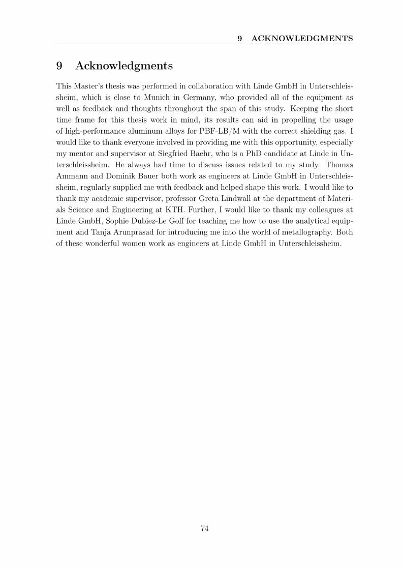
9 ACKNOWLEDGMENTS
9 Acknowledgments
This Master’s thesis was performed in collaboration with Linde GmbH in Unterschleis-sheim, which is close to Munich in Germany, who provided all of the equipment aswell as feedback and thoughts throughout the span of this study. Keeping the shorttime frame for this thesis work in mind, its results can aid in propelling the usageof high-performance aluminum alloys for PBF-LB/M with the correct shielding gas. Iwould like to thank everyone involved in providing me with this opportunity, especiallymy mentor and supervisor at Siegfried Baehr, who is a PhD candidate at Linde in Un-terschleissheim. He always had time to discuss issues related to my study. ThomasAmmann and Dominik Bauer both work as engineers at Linde GmbH in Unterschleis-sheim, regularly supplied me with feedback and helped shape this work. I would like tothank my academic supervisor, professor Greta Lindwall at the department of Materi-als Science and Engineering at KTH. Further, I would like to thank my colleagues atLinde GmbH, Sophie Dubiez-Le Goff for teaching me how to use the analytical equip-ment and Tanja Arunprasad for introducing me into the world of metallography. Bothof these wonderful women work as engineers at Linde GmbH in Unterschleissheim.
74
10 References
[1] C. Galy, E. Le Guen, E. Lacoste, and C. Arvieu, “Main defects observed in alu-minum alloy parts produced by SLM: From causes to consequences,” Additivemanufacturing, vol. 22, pp. 165–175, 2018.
[2] S. Ly, A. M. Rubenchik, S. A. Khairallah, G. Guss, and M. J. Matthews, “Metalvapor micro-jet controls material redistribution in laser powder bed fusion additivemanufacturing,” Scientific Reports, vol. 7, p. 4085, Jun 2017.
[3] C. Pauzon, B. Hoppe, T. Pichler, S. Dubiez-Le Goff, P. Forêt, T. Nguyen, andE. Hryha, “Reduction of incandescent spatter with helium addition to the processgas during laser powder bed fusion of Ti-6Al-4V,” CIRP Journal of ManufacturingScience and Technology, vol. 35, pp. 371–378, 2021.
[4] A. B. Anwar and Q.-C. Pham, “Study of the spatter distribution on the powderbed during selective laser melting,” Additive manufacturing, vol. 22, pp. 86–97,2018.
[5] X. Nie, H. Zhang, H. Zhu, Z. Hu, L. Ke, and X. Zeng, “Effect of Zr contenton formability, microstructure and mechanical properties of selective laser meltedZr modified Al-4.24Cu-1.97Mg-0.56Mn alloys,” Journal of alloys and compounds,vol. 764, pp. 977–986, 2018.
[6] A. Mehta, L. Zhou, T. Huynh, S. Park, H. Hyer, S. Song, Y. Bai, D. D. Imholte,N. E. Woolstenhulme, D. M. Wachs, and Y. Sohn, “Additive manufacturing andmechanical properties of the dense and crack free Zr-modified aluminum alloy6061 fabricated by the laser-powder bed fusion,” Additive Manufacturing, vol. 41,p. 101966, 2021.
[7] H. Zhang, H. Zhu, X. Nie, J. Yin, Z. Hu, and X. Zeng, “Effect of Zirconium additionon crack, microstructure and mechanical behavior of selective laser melted Al-Cu-Mg alloy,” Scripta Materialia, vol. 134, pp. 6–10, 2017.
[8] S. R. Ch, A. Raja, P. Nadig, R. Jayaganthan, and N. Vasa, “Influence of work-ing environment and built orientation on the tensile properties of selective lasermelted AlSi10Mg alloy,” Materials science & engineering. A, Structural materials: properties, microstructure and processing, vol. 750, pp. 141–151, 2019.
[9] F. Matos, R. Godina, C. Jacinto, H. Carvalho, I. Ribeiro, and P. Peças, “AdditiveManufacturing: Exploring the Social Changes and Impacts,” Sustainability (Basel,Switzerland), vol. 11, no. 14, p. 3757, 2019.
75
[10] P. Forêt, “Can AM help fight climate change with a moresustainable production?.” https://www.3dprintingmedia.network/can-am-help-fight-climate-change-with-a-more-sustainable-production/, 2021.Accessed: 2021-10-05.
[11] D. Buchbinder, H. Schleifenbaum, S. Heidrich, W. Meiners, and J. Bültmann,“High Power Selective Laser Melting (HP SLM) of Aluminum Parts,” Physicsprocedia, vol. 12, pp. 271–278, 2011.
[12] United Nations, “The 17 Goals, Sustainable Development.” https://sdgs.un.org/goals. Accessed: 2021-10-08.
[13] D. L. Bourell, W. Frazier, H. Kuhn, and M. Seifi, ASM Handbook®, Volume 24 -Additive Manufacturing Processes. 2020.
[14] “Additve manufacturing - General principles - Terminology (ISO/ASTM52900:2017,” standard.
[15] S. Kumar, Additive Manufacturing Processes. Springer, Cham, 1st ed. 2020. ed.,2020.
[16] M. Brandt, Laser Additive Manufacturing: Materials, Design, Technologies, andApplications. Woodhead Publishing series in electronic and optical materials,Cambridge: Elsevier Science & Technology, 2016.
[17] W. J. Sames, F. A. List, S. Pannala, R. R. Dehoff, and S. S. Babu, “The metallurgyand processing science of metal additive manufacturing,” International MaterialsReviews, vol. 61, no. 5, pp. 315–360, 2016.
[18] K. Van Praet, “Metal 3D Printing: How to Counter the Impact of Recoaters.”https://www.materialise.com/en/blog/metal-3D-printing-recoaters, Jul 2017. Ac-cessed: 2021-05-07.
[19] T. Kurzynowski, E. Chlebus, B. Kuźnicka, and J. Reiner, “Parameters in selectivelaser melting for processing metallic powders,” in High Power Laser MaterialsProcessing: Lasers, Beam Delivery, Diagnostics, and Applications (E. Beyer andT. Morris, eds.), vol. 8239, pp. 317 – 322, International Society for Optics andPhotonics, SPIE, 2012.
[20] I. Yadroitsev, P. Bertrand, and I. Smurov, “Parametric analysis of the selectivelaser melting process,” Applied Surface Science, vol. 253, no. 19, pp. 8064–8069,2007. Photon-Assisted Synthesis and Processing of Functional Materials.
[21] E. Louvis, P. Fox, and C. J. Sutcliffe, “Selective laser melting of aluminium com-ponents,” Journal of materials processing technology, vol. 211, no. 2, pp. 275–284,2011.
76
[22] P. Bidare, I. Bitharas, R. Ward, M. Attallah, and A. Moore, “Fluid and particledynamics in laser powder bed fusion,” Acta materialia, vol. 142, pp. 107–120, 2018.
[23] C. Qiu, C. Panwisawas, M. Ward, H. C. Basoalto, J. W. Brooks, and M. M. Attal-lah, “On the role of melt flow into the surface structure and porosity developmentduring selective laser melting,” Acta materialia, vol. 96, pp. 72–79, 2015.
[24] L. Zhou, H. Hyer, S. Park, H. Pan, Y. Bai, K. P. Rice, and Y. Sohn, “Microstruc-ture and mechanical properties of Zr-modified aluminum alloy 5083 manufacturedby laser powder bed fusion,” Additive Manufacturing, vol. 28, pp. 485–496, 2019.
[25] T. DebRoy, H. Wei, J. Zuback, T. Mukherjee, J. Elmer, J. Milewski, A. Beese,A. Wilson-Heid, A. De, and W. Zhang, “Additive manufacturing of metallic com-ponents – Process, structure and properties,” Progress in materials science, vol. 92,no. C, pp. 112–224, 2018.
[26] N. Read, W. Wang, K. Essa, and M. M. Attallah, “Selective laser melting ofAlSi10Mg alloy: Process optimisation and mechanical properties development,”Materials & Design (1980-2015), vol. 65, pp. 417–424, 2015.
[27] S. Liu and H. Guo, “Balling Behavior of Selective Laser Melting (SLM) MagnesiumAlloy,” Materials, vol. 13, no. 16, p. 3632, 2020.
[28] W. E. King, H. D. Barth, V. M. Castillo, G. F. Gallegos, J. W. Gibbs, D. E. Hahn,C. Kamath, and A. M. Rubenchik, “Observation of keyhole-mode laser melting inlaser powder-bed fusion additive manufacturing,” Journal of materials processingtechnology, vol. 214, no. 12, pp. 2915–2925, 2014.
[29] J. Oliveira, T. Santos, and R. Miranda, “Revisiting fundamental welding con-cepts to improve additive manufacturing: From theory to practice,” Progress inmaterials science, vol. 107, p. 100590, 2020.
[30] E. Olakanmi, R. Cochrane, and K. Dalgarno, “A review on selective laser sinter-ing/melting (SLS/SLM) of aluminium alloy powders: Processing, microstructure,and properties,” Progress in Materials Science, vol. 74, pp. 401–477, 2015.
[31] A. Ahmadi, R. Mirzaeifar, N. S. Moghaddam, A. S. Turabi, H. E. Karaca, andM. Elahinia, “Effect of manufacturing parameters on mechanical properties of316L stainless steel parts fabricated by selective laser melting: A computationalframework,” Materials & design, vol. 112, pp. 328–338, 2016.
[32] Y. Li and D. Gu, “Parametric analysis of thermal behavior during selective lasermelting additive manufacturing of aluminum alloy powder,” Materials in engi-neering, vol. 63, pp. 856–867, 2014.
77
[33] S. Zhang, S. Rauniyar, S. Shrestha, A. Ward, and K. Chou, “An experimentalstudy of tensile property variability in selective laser melting,” Journal of Man-ufacturing Processes, vol. 43, pp. 26–35, 2019. Special Issue on New Trends inManufacturing Processes Research.
[34] H. Gong, K. Rafi, H. Gu, T. Starr, and B. Stucker, “Analysis of defect generation inTi–6Al–4V parts made using powder bed fusion additive manufacturing processes,”Additive manufacturing, vol. 1-4, pp. 87–98, 2014.
[35] A. du Plessis, “Effects of process parameters on porosity in laser powder bed fusionrevealed by X-ray tomography,” Additive Manufacturing, vol. 30, p. 100871, 2019.
[36] C. L. A. Leung, S. Marussi, M. Towrie, J. del Val Garcia, R. C. Atwood, A. J.Bodey, J. R. Jones, P. J. Withers, and P. D. Lee, “Laser-matter interactions inadditive manufacturing of stainless steel SS316L and 13-93 bioactive glass revealedby in situ X-ray imaging,” Additive Manufacturing, vol. 24, pp. 647–657, 2018.
[37] C. L. A. Leung, S. Marussi, R. C. Atwood, M. Towrie, P. J. Withers, and P. D.Lee, “In situ X-ray imaging of defect and molten pool dynamics in laser additivemanufacturing,” Nature Communications, vol. 9, p. 1355, Apr 2018.
[38] C. Weingarten, D. Buchbinder, N. Pirch, W. Meiners, K. Wissenbach, andR. Poprawe, “Formation and reduction of hydrogen porosity during selectivelaser melting of AlSi10Mg,” Journal of materials processing technology, vol. 221,pp. 112–120, 2015.
[39] C. Qiu, C. Panwisawas, M. Ward, H. C. Basoalto, J. W. Brooks, and M. M. Attal-lah, “On the role of melt flow into the surface structure and porosity developmentduring selective laser melting,” Acta Materialia, vol. 96, pp. 72–79, 2015.
[40] C. Tang, K. Le, and C. Wong, “Physics of humping formation in laser powder bedfusion,” International journal of heat and mass transfer, vol. 149, p. 119172, 2020.
[41] K. Anderson, J. Weritz, and J. G. Kaufman, “Part II. Wrought Aluminum Alloy,”in ASM Handbook®, Volume 2B - Properties and Selection of Aluminum Alloys,ASM International, 2019.
[42] P. Mair, V. S. Goettgens, T. Rainer, N. Weinberger, I. Letofsky-Papst, S. Mitsche,and G. Leichtfried, “Laser powder bed fusion of nano-CaB6 decorated 2024 alu-minum alloy,” Journal of alloys and compounds, vol. 863, p. 158714, 2021.
[43] M. Hasegawa, “Chapter 3.3 - Ellingham Diagram,” in Treatise on Process Metal-lurgy (S. Seetharaman, ed.), pp. 507–516, Boston: Elsevier, 2014.
[44] S. Das, “Physical Aspects of Process Control in Selective Laser Sintering of Met-als,” Advanced engineering materials, vol. 5, no. 10, pp. 701–711, 2003.
78
[45] Wikipedia, “Ellingham diagram.” https://en.wikipedia.org/wiki/Ellingham_diagram#/media/File:Ellingham_Richardson-diagram_english.svg, 2021. Ac-cessed: 2021-05-31.
[46] X. Zhou and J. de Hosson, “Wetting Kinetics of Liquid Aluminum on an AL2O3Surface,” Journal of materials science, vol. 30, no. 14, pp. 3571–3575, 1995.
[47] M. Tang, P. C. Pistorius, S. Narra, and J. L. Beuth, “Rapid Solidification: SelectiveLaser Melting of AlSi10Mg,” JOM (1989), vol. 68, no. 3, pp. 960–966, 2016.
[48] T. Yang, T. Liu, W. Liao, E. MacDonald, H. Wei, C. Zhang, X. Chen, andK. Zhang, “Laser powder bed fusion of AlSi10Mg: Influence of energy intensi-ties on spatter and porosity evolution, microstructure and mechanical properties,”Journal of Alloys and Compounds, vol. 849, p. 156300, 2020.
[49] W. E. King, A. T. Anderson, R. M. Ferencz, N. E. Hodge, C. Kamath, S. A.Khairallah, and A. M. Rubenchik, “Laser powder bed fusion additive manufactur-ing of metals; physics, computational, and materials challenges,” Applied PhysicsReviews, vol. 2, no. 4, p. 041304, 2015.
[50] L. Nastac, K. Pericleous, A. S. Sabau, L. Zhang, and B. G. Thomas, CFD Modelingand Simulation in Materials Processing 2018. The Minerals, Metals & MaterialsSeries, Cham: Springer International Publishing AG, 2018.
[51] M. J. Matthews, G. Guss, S. A. Khairallah, A. M. Rubenchik, P. J. Depond,and W. E. King, “Denudation of metal powder layers in laser powder bed fusionprocesses,” Acta Materialia, vol. 114, pp. 33–42, 2016.
[52] M. Simonelli, C. Tuck, N. T. Aboulkhair, I. Maskery, I. Ashcroft, R. D. Wildman,and R. Hague, “A Study on the Laser Spatter and the Oxidation Reactions Dur-ing Selective Laser Melting of 316L Stainless Steel, Al-Si10-Mg, and Ti-6Al-4V,”Metallurgical and materials transactions. A, Physical metallurgy and materialsscience, vol. 46, no. 9, pp. 3842–3851, 2015.
[53] P. Bidare, I. Bitharas, R. M. Ward, M. M. Attallah, and A. J. Moore, “Laser pow-der bed fusion in high-pressure atmospheres,” International journal of advancedmanufacturing technology, vol. 99, no. 1-4, pp. 543–555, 2018.
[54] A. Ladewig, G. Schlick, M. Fisser, V. Schulze, and U. Glatzel, “Influence of theshielding gas flow on the removal of process by-products in the selective lasermelting process,” Additive Manufacturing, vol. 10, pp. 1–9, 2016.
[55] Z. Boukha, J. M. Sánchez-Amaya, L. González-Rovira, E. D. Rio, G. Blanco, andJ. Botana, “Influence of CO2-Ar Mixtures as Shielding Gas on Laser Welding of Al-Mg Alloys,” Metallurgical and Materials Transactions A, vol. 44, pp. 5711–5723,Dec 2013.
79
[56] C. Pauzon, A. Raza, E. Hryha, and P. Forêt, “Oxygen balance during laser powderbed fusion of Alloy 718,” Materials & Design, vol. 201, p. 109511, 2021.
[57] B. Ferrar, L. Mullen, E. Jones, R. Stamp, and C. Sutcliffe, “Gas flow effects onselective laser melting (SLM) manufacturing performance,” Journal of materialsprocessing technology, vol. 212, no. 2, pp. 355–364, 2012.
[58] J. W. Leachman, Thermodynamic Properties of Cryogenic Fluids. InternationalCryogenics Monograph Series, 2nd ed. 2017.. ed., 2017.
[59] X. Wang, L. Zhang, M. Fang, and T. Sercombe, “The effect of atmosphere onthe structure and properties of a selective laser melted Al–12Si alloy,” Materialsscience & engineering. A, Structural materials : properties, microstructure andprocessing, vol. 597, pp. 370–375, 2014.
[60] O. O. Oladimeji and E. Taban, “Trend and innovations in laser beam welding ofwrought aluminum alloys,” Welding in the world, vol. 60, no. 3, pp. 415–457, 2016.
[61] D. Huang, J. C. McClure, and A. C. Nunes, “Gas contamination during plasmawelding in Al-Li alloy 2195,” Science and technology of welding and joining, vol. 2,no. 5, pp. 209–212, 1997.
[62] G. Brauer, Handbook of Preparative Inorganic Chemistry V1. Saint Louis: ElsevierScience & Technology, 2012.
[63] K. Weman, Welding processes handbook. Woodhead Publishing Series in Weldingand Other Joining Technologies, Oxford ; Philadelphia: Woodhead Pub., 2nded.. ed., 2012.
[64] R. J. Breakspere, “High-temperature oxidation of aluminium in various gases,”Journal of Applied Chemistry, vol. 20, no. 7, pp. 208–212, 1970.
[65] S. Lu, H. Fujii, and K. Nogi, “Marangoni convection in weld pool in CO2-Ar-shielded gas thermal arc welding,” Metallurgical and Materials Transactions A,vol. 35, pp. 2861–2867, Sep 2004.
[66] C. R. Heiple, J. R. Roper, R. T. Stagner, and R. J. Aden, “Surface-active elementeffects on the shape of GTA, laser, and electron-beam welds,” Weld. Res. Suppl.;(United States), 3 1983.
[67] A. Spierings, K. Dawson, P. Dumitraschkewitz, S. Pogatscher, and K. Wegener,“Microstructure characterization of SLM-processed Al-Mg-Sc-Zr alloy in the heattreated and HIPed condition,” Additive Manufacturing, vol. 20, pp. 173–181, 2018.
[68] M. L. Montero-Sistiaga, R. Mertens, B. Vrancken, X. Wang, B. Van Hooreweder,J.-P. Kruth, and J. Van Humbeeck, “Changing the alloy composition of Al7075 for
80
better processability by selective laser melting,” Journal of Materials ProcessingTechnology, vol. 238, pp. 437–445, 2016.
[69] J. Liu, P. Yao, N. Zhao, C. Shi, H. Li, X. Li, D. Xi, and S. Yang, “Effect ofminor Sc and Zr on recrystallization behavior and mechanical properties of novelAl–Zn–Mg–Cu alloys,” Journal of Alloys and Compounds, vol. 657, pp. 717–725,2016.
[70] L. Mondolfo, “Al–Zr Aluminum–Zirconium system,” in Aluminum Alloys (L. Mon-dolfo, ed.), pp. 413–416, Butterworth-Heinemann, 1976.
[71] aconity3D, “Aconity MINI.” https://aconity3d.com/products/aconity-mini/. Ac-cessed: 2021-06-29.
[72] Engineering ToolBox, “Elements - Melting Points.” https://www.engineeringtoolbox.com/elements-melting-points-d_1863.html, 2013. Accessed:2021-10-04.
[73] E. Almqvist, History of Industrial Gases. Springer, 2012.
[74] Engineering ToolBox, “Specific Heat and Individual Gas Constants of Gases.”https://www.engineeringtoolbox.com/specific-heat-capacity-gases-d_159.html,2003. Accessed: 2021-05-27.
[75] Engineering ToolBox, “Carbon dioxide - Density andSpecific Weight.” https://www.engineeringtoolbox.com/carbon-dioxide-density-specific-weight-temperature-pressure-d_2018.html,2018. Accessed: 2021-08-09.
[76] Engineers Edge, “Thermal Conductivity of Gases Chart.” https://www.engineersedge.com/heat_transfer/thermal-conductivity-gases.htm. Accessed:2021-10-05.
[77] R. M. German, Powder metallurgy and particulate materials processing : the pro-cesses, materials, products, properties and applications. Princeton, N.J.: MetalPowder Industries Federation, 2005.
[78] E. Scholz, Karl Fischer Titration Determination of Water. Chemical LaboratoryPractice, Springer Berlin Heidelberg, 1st ed. 1984. ed., 1984.
[79] Mettler Toledo, “Karl Fischer Titration.” https://www.mt.com/de/en/home/library/product-brochures/lab-analytical-instruments/Karl-Fischer-Titrators.html, 2021. Accessed: 2021-07-12.
[80] R. Aro, M. W. Ben Ayoub, I. Leito, and r. Georgin, “Moisture in Solids: Compar-ison Between Evolved Water Vapor and Vaporization Coulometric Karl FischerMethods,” International journal of thermophysics, vol. 41, no. 8, 2020.
81
[81] A. Cooke and J. Slotwinski, Properties of Metal Powders for Additive Manufac-turing: A Review of the State of the Art of Metal Powder Property Testing. NISTInteragency/Internal Report (NISTIR), National Institute of Standards and Tech-nology, Gaithersburg, MD, 07 2012.
[82] LECO, “836 Series Elemental Analyer, Determine Oxygen, Hydrogen, and Nitro-gen in Inorganic Samples.” https://www.leco.com/product/836-series, 2021. Ac-cessed: 2021-08-25.
[83] Microtrac, “Particle and Shape Analyzer Camsizer® X2.” https://www.microtrac.com/products/particle-size-shape-analysis/dynamic-image-analysis/camsizer-x2/, 2021. Accessed: 2021-08-24.
[84] A. Thornton, J. Saad, and J. Clayton, “Measuring the critical attributes of AMpowders,” Metal Powder Report, vol. 74, no. 6, pp. 314–319, 2019.
[85] J. A. Slotwinski, E. J. Garboczi, and K. M. Hebenstreit, “Porosity Measurementsand Analysis for Metal Additive Manufacturing Process Control,” Journal of re-search of the National Institute of Standards and Technology, vol. 119, no. 1,pp. 494–528, 2014.
[86] A. Spierings, M. Schneider, and R. Eggenberger, “Comparison of density mea-surement techniques for additive manufactured metallic parts,” Rapid prototypingjournal, vol. 17, no. 5, pp. 380–386, 2011.
[87] D. Selvamuthu and D. Das, Introduction to Statistical Methods, Design of Exper-iments and Statistical Quality Control. Singapore: Springer Singapore, 2018.
[88] G. Cumming, Understanding the new statistics : effect sizes, confidence inter-vals, and meta-analysis. Multivariate applications book series, Routledge, 1stedition. ed., 2012.
[89] R. A. Donnelly, Statistics. Idiot’s guides, Alpha, third edition, first americanedition.. ed., 2016.
[90] S. Glen, “Coefficicent of Determination (R Squared): Definition, Cal-culation.” https://www.statisticshowto.com/probability-and-statistics/coefficient-of-determination-r-squared/, 2021.
[91] W. P. Vogt, Dictionary of statistics & methodology a nontechnical guide for thesocial sciences. Los Angeles, [Calif.] ; London: SAGE, 3rd ed.. ed., 2005.
[92] J. Fernando, “R-Squared.” https://www.investopedia.com/terms/r/r-squared.asp.
82

TRITA ITM-EX 2021:600
www.kth.se
Related Documents


![Rosetta Langmuir probe performance - DiVA portal680862/FULLTEXT01.pdf1.3.1 Debye shielding and Debye length Debye shielding [1] is an innate ability of the plasma to shield out local](https://static.cupdf.com/doc/110x72/60ffba69c4d405429359b4af/rosetta-langmuir-probe-performance-diva-680862fulltext01pdf-131-debye-shielding.jpg)