6-46. Determine the moment M that should be applied to the beam in order to create a compressive stress at point D of <TD = 30 MPa. Also sketch the stress distribution acting over the cross section and compute the maximum stress developed in the beam. M 25 mm 25nu 25 mm Section Property: / = 1(0.2)(0.2')-— (0.15)(O.I5 5 ) =91.14583(10'') m' Bending Stress: Applying ihe flexure formula Mv c= T M0.075) M = 35458 N m = 36.5 kN m Me 36458(0.11 / 91.I4583(10-») •=40.0 MPa Ans 266

Welcome message from author
This document is posted to help you gain knowledge. Please leave a comment to let me know what you think about it! Share it to your friends and learn new things together.
Transcript

© 2008 by R.C. Hibbeler. Published by Pearson Prentice Hall, Pearson Education, Inc., Upper Saddle River, NJ. All rights reserved. This material is protected under allcopyright laws as they currently exist. No portion of this material may be reproduced, in any form or by any means, without permission in writing from the publisher.
6-45. The beam is subjected to a moment M. Determinethe percentage of this moment that is resisted by thestresses acting on both the top and bottom boards, A and B,of the beam.
Section Property:
/ = — <0.2)(0.2')-— (0.15)(0.153) =91.14583(10-') m4
Bending Stress: Applying the flexure formula
Afv
B : • 25 mm
25mm ' "» 150mm
M(O.l)£" 91.14583(11)-*)
M(0.075)
= 1097.143 M
= 822.857 M
Resultant Force and Moment: For hoard A or B
F = 821857M(0.025)(0.2)I
+ -(I097.I43M - 822.857Af>( 0.0251(0.2)
= 4 800 M
M' = F(O.I76I9) = 4.80A/IO.I7619) =0.8457 M
— | = 0.8457( 100%) = 84.6 * Ans
6-46. Determine the moment M that should be applied tothe beam in order to create a compressive stress at point Dof <TD = 30 MPa. Also sketch the stress distribution actingover the cross section and compute the maximum stressdeveloped in the beam. M
25 mm
25nu25 mm
Section Property:
/ = 1(0.2)(0.2')-— (0.15)(O.I55) =91.14583(10'') m'
Bending Stress: Applying ihe flexure formula
Mvc=T
M0.075)
M = 35458 N m = 36.5 kN m
Me 36458(0.11/ 91.I4583(10-»)
•=40.0 MPa Ans
266

© 2008 by R.C. Hibbeler. Published by Pearson Prentice Hall, Pearson Education, Inc., Upper Saddle River, NJ. All rights reserved. This material is protected under allcopyright laws as they currently exist. No portion of this material may be reproduced, in any form or by any means, without permission in writing from the publisher.
6-57. Determine the resultant force the bending stressesproduce on the top board A of the beam if M = 1 kip • ft.
Section Properties:
0.75(10)(1.5) + 7.5(l)( 12) + 14.2S(6)( 1.5)IA 10(1.5)
= 6.375 in.
.5') + 10(1.5)<6.375-0.75)2
+ -M6)( 1.5') + 61 1.5)( 14.25 -6.375)'
= 1 196.4375 in'
Bending Stress: Applying Ihe flexure formula
Myc 1000(12X6.375-1.5)
63.94 psi
/ 1196.4375
MyD 1000( 12)16.375)<To = ~7~: 1196.4375
The Resultant Force: For lop board A
F =-(63.94 + 48.90) (10)(1.5) = 846 Ib
= 48.90 psi
Ans
6-58. The control level is used on a riding lawn mower.Determine the maximum bending stress in the lever atsection a-a if a force of 20 Ib is applied to the handle. Thelever is supported by a pin at A and a wire at B. Section a-ais square,0.25 in. by 0.25 in.
20 Ib
20(2) - M - 0 ; M = 40 Ib in
Me 40(0.125)/ ~ £(0.25X0.25')
15.4 ksi
272

© 2008 by R.C. Hibbeler. Published by Pearson Prentice Hall, Pearson Education, Inc., Upper Saddle River, NJ. All rights reserved. This material is protected under allcopyright laws as they currently exist. No portion of this material may be reproduced, in any form or by any means, without permission in writing from the publisher.
6-93. The beam is subjected to the loading shown. Deter-mine its required cross-sectional dimension a, if the allowablebending stress for the material is cranow = 150 MPa.
40 kN/m 60 kN
-2m- -1m-
2!*'
Support Reactions: As shown on FBD.
Section Properties:
. ^ £vA ^ X h) «+ H r«) ( f")
" "4«V««frotoil
r I ^1 I \ /• 1 V 5 1 V
/ = — 10) -a + 0 - 0 — a — a\2 U >/ b A 12 6 )
2 5
37 .Internal Moment: As shown on the moment diagram
Allowable Bending Stress: The maximum moment isA/,,,, = 60.0 kN m as indicated on the moment diagramApplying the flexure formula
150(10')60.0(IO')(a-ia)
a=O.I599 m = 160mm Ans
6-94. The wing spar ABD of a light plane is made from2014-T6 aluminum and has a cross-sectional area of 1.27 in ,a depth of 3 in., and a moment of inertia about its neutralaxis of 2.68 in4. Determine the absolute maximum bendingstress in the spar if the anticipated loading is to be as shown.Assume A, B, and C are pins. Connection is made along thecentral longitudinal axis of the spar.
801b/in.
2ft
3 f t - -6 f t -
10 li/.
AM
Note thai 2S.8 ksi < ar = 60 ksi OK
291
D

© 2008 by R.C. Hibbeler. Published by Pearson Prentice Hall, Pearson Education, Inc., Upper Saddle River, NJ. All rights reserved. This material is protected under allcopyright laws as they currently exist. No portion of this material may be reproduced, in any form or by any means, without permission in writing from the publisher.
6-98. The wood beam is subjected to the uniform loadof w = 200 Ib/ft. If the allowable bending stress for thematerial is <ranow = 1.40 ksi, determine the required dimen-sion b of its cross section. Assume the support at A is a pinand R is a roller.
.irrrrrm
V(lb)
Allowable Bending Stress: The maximum moment isMmll = 5688.89 Ib ft as indicated on moment diagram.Applying the flexure formula
M,.,c
l.40( 10')2844.44(12X0.75*)
b = 4.02 in. Ans
6-99. The wood beam has a rectangular cross section inthe proportion shown. Determine its required dimension bif the allowable bending stress is cral)ow = 10 MPa.
500 N/m
2 m — 2m
r I ,fm
Allowable Bending Stress: The maximum moment isWm<1 = 562.5 N m as indicated on the moment diagram.Applying the flexure formula
7#>
;^N\ L, *
-zsoMCA/-*-;
10( I06) =562.5(0.75t)
b = 0.05313m = 53.1 mm Ans
294
© 2008 by R.C. Hibbeler. Published by Pearson Prentice Hall, Pearson Education, Inc., Upper Saddle River, NJ. All rights reserved. This material is protected under allcopyright laws as they currently exist. No portion of this material may be reproduced, in any form or by any means, without permission in writing from the publisher.
*6-120. The composite beam is made of 6061-T6 aluminum(A) and C83400 red brass (£'). If the height h = 40mm,determine the maximum moment that can be applied to thebeam if the allowable bending stress for the aluminum is(<railow)ai = 128 MPa and for the brass (craUow)br = 35 MPa.
k
50 mm
] 150mm
Section Properties: For transformed section.
Eb, lOl.O(lO')btl, = nbii = 0.68218(0.15) = 0.10233m
. _ lyA
_ 0.025(0.10233)(0.05) + (0.07)(0.15)(0.04)0.10233(0.051 + 0.15(0.04)
= 0.049289 m
4M-|5(ft«mj)(a051) +0.10233(0.051(0.049289-0.025)2
•|-J2(0.15)(0.041)-HO.I5(0.04)(0.07-0.049289)!
= 7.45799(10-') m4
Allowable Bending Stress: Applying the flexure formula
Assume failure of red brass
Me(<T-"°")br = £7
M(0.09 -0.049289)35( 10')
7.45799( lO-«)= 6412N m = « . 4 l k N - m (controls!) Ans
Assume failure of aluminium
Me
7.45799(10-')]
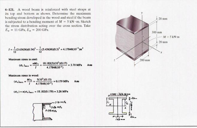
6-121. A wood beam is reinforced with steel straps atits lop and bollom as shown. Determine the maximumbending stress developed in the wood and steel if the beamis subjected to a bending moment of M = 5 kN • m. Sketchthe stress distribution acting over the cross section. Take£w = 11 GPa, EA = 200 GPa.
7 = —(3.63636X0.34)' - — (3.43636)(0.3)' = 4.17848(10"')m'
Maximum stress in steel:_nMc, _ 18.I82(S)(10')(0.17)
'"' "" ~ 7 4.17848(10-')
Maximum stress in wood:
3.70 MPa Ans
20 mm
4- — M = 5kN-m
20 mm
= 0.179 MPa An7 4.17848(10-')'
»st) = n(<rw)-m, = 18.182(0.179) = 3.26 MPa
1\ 3U Mf.FI rt
309
Related Documents


![TAMIL NADU GOVERNMENT GAZETTE - tniuscbe.org OF NAMES No. 50] CHENNAI, WEDNESDAY, DECEMBER 24, 2008 ... M. REVATHI. Chennai, 15th December 2008. I, P. Sukumaran, son of Thiru C. Palanisamy,](https://static.cupdf.com/doc/110x72/5ab9714c7f8b9ac60e8e110d/tamil-nadu-government-gazette-of-names-no-50-chennai-wednesday-december-24.jpg)


