Determination of the optimum flank line modifications for gear pairs and for planetary stages Authors: Dr. Ing. Ulrich Kissling, KISSsoft AG Dipl. Ing. Hanspeter Dinner, EES-KISSsoft GmbH KISSsoft AG Rosengartenstrasse 4 8608 Bubikon Switzerland Tel: +41 55 254 20 61 Fax: +41 55 254 20 51 [email protected] www.KISSsoft.AG

Welcome message from author
This document is posted to help you gain knowledge. Please leave a comment to let me know what you think about it! Share it to your friends and learn new things together.
Transcript
Determination of the optimum flank line modifications for gear pairs and for planetary stages
Authors:
Dr. Ing. Ulrich Kissling, KISSsoft AG
Dipl. Ing. Hanspeter Dinner, EES-KISSsoft GmbH
KISSsoft AG
Rosengartenstrasse 4
8608 Bubikon
Switzerland
Tel: +41 55 254 20 61
Fax: +41 55 254 20 51
www.KISSsoft.AG
2 / 25
Abstract
Planetary gear stages are used in many different applications, from automatic transmissions for vehicles,
vertical roller mill gearboxes or in the drive train of wind turbines. While it is still not an easy task to optimize
the flank line modification for one gear pair using loaded contact analysis (LTCA), in planetary stages
typically 6 or more gear pairs are in concurrent contact, creating therefore a much more complicated
problem to solve. To find the optimum flank line modification using LTCA is therefore quite time consuming.
In the current (dating to 2006) edition of the ISO6336 standard for the load capacity calculation of spur and
helical gears, a new annex E was added: "Analytical determination of load distribution". It is a well-
documented procedure to determine the load distribution and get a precise number for the face load factor
KHβ, which is otherwise one of the difficult topics in ISO6336-1 using method C.
With some additional improvements, this algorithm becomes a ‘1-dimensional contact analysis’. The main
advantage of this approach is the low calculation time, which is much faster than a two dimensional (in lead
and profile direction) contact analysis.
For planetary gear sets, the application of the ISO6336-1, annex E, algorithm has to be adapted to the
specific peculiarities of the combination of sun shaft, planet carrier, with pin and planet, and ring gear. In
particular, the torsional deformation (calculated e.g. using FEM) and tilting of the planetary carrier, the
torsion and tilting of the sun shaft and the movement of the planets on their bearings needs to be combined.
Then all the gear meshes in the system have to be analyzed simultaneously.
In this paper, we describe the combination of this calculation of the line load distribution with an optimization
algorithm to find the most suitable flank line modifications. The algorithm automatically varies different
combinations of flank line modifications and calculates the resulting line load distribution for several torque
levels. With this approach, the best flank line modification is simple to find. Especially in applications, where
complex duty cycles have to be handled, it would otherwise be hard to decide for which load level the
modifications should be optimized, while with this approach, all load levels may be taken into account when
designing modifications.
Some practical examples are discussed. The optimum flank line modification for a wind turbine is
determined including distortion of the planet carrier, deformation of sun shaft, planet-bearing-pin and ring
gear. The results are compared to typical findings in load tests. In another project, a typical horizontal roller
mill gear box with a so-called flex pin concept is compared to a classic planet-pin concept to evaluate the
behavior under extreme tilting of the planet carrier.
3 / 25
1 Introduction
The face load factor KH, which in rating equations represents the load distribution over the common face
width in meshing gears, is one of the most important items for a gear strength calculation. In the
international standard for cylindrical gear rating, the ISO6336-1 [1], using method C, some formulas are
proposed to get a value for this factor. But as the formulas are simplified, the result is often not very
realistic, in particular for planetary gears.
In the last edition in 2006 of the ISO6336 standard for the load capacity calculation of spur and helical gears
a new annex E was added: "Analytical determination of load distribution". This annex is entirely based on
the AGMA 927-A01 [3] standard. It is a well-documented procedure to get a direct and precise number for
the face load factor.
Today an increasing number of gear designers are using loaded tooth contact analysis (LTCA) methods [4]
to get precise information on the load distribution in both dimensions of the flank (lead and profile direction)
on the full gear flank. A contact analysis is time consuming and does not permit to get a value for KH, as
defined by the ISO or AGMA standard. A contact analysis result combines different factors of ISO6336 as
KH, KH, Z, Z, ZB, ZD and buttressing effects, etc; thus to ‘extract’ KH from a TCA is not possible.
The use of the algorithm, as proposed by ISO6336-1, Annex E, is a good solution to get proper values for
KH; it is simpler and therefore much quicker than a contact analysis calculation. The paper explains how
this algorithm can be applied for gear pair rating in a parallel shaft gearbox, for ratings with load spectra and
for planetary systems with interdependent meshings between sun, all planets and ring gear.
2 Determination of the load distribution over the face width
The cause for the uneven load distribution over the face width are flank line deviations in the contact plane
of two gears. Deviations are caused mainly by elastic deformations of the shaft, stiffness and clearance of
bearings and housing, manufacturing tolerances and thermal deformations.
The determination of the load distribution is – as documented in the gear theory – performed in two steps.
At first the gap in the tooth contact is calculated. Then, using the tooth mesh stiffness (c [1]), the line load
distribution is determined. This approach is well documented in ISO6336-1; but the calculation along
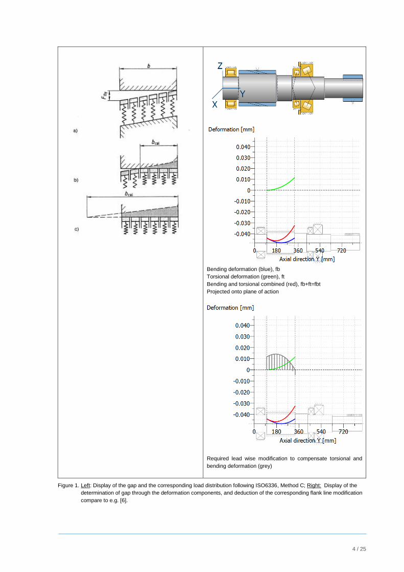
ISO6336, Method C, simplifies the real situation through assumption of a linear load distribution (fig. 1, left
side).
2.1 Determination of the gap in the tooth contact
Above or e.g.in [6], the deduction of the gap through superposition of bending and torsion deformation is
explained (fig. 1, right). As additional simplification it is assumed, that the mating gear is infinitely stiff.
Without flank line modification, in the example shown in fig.1 (right), the load would be bigger on the torque
input side. If a modification as shown in fig.1 is applied on the pinion flank line, then a uniform load
distribution would result. This is true, if the meshing gear is effectively very stiff – or if also on the mating
gear a flank line modification is applied. In the formulas for KHof ISO6336-1 (chapter 7) it is assumed, that
the pinion shaft is much softer than the gear shaft, thus the deformation of the gear shaft is much less and
can be neglected. For gear pairs with a reduction i > 2, in many cases this is an acceptable assumption.
4 / 25
Bending deformation (blue), fb
Torsional deformation (green), ft
Bending and torsional combined (red), fb+ft=fbt
Projected onto plane of action
Required lead wise modification to compensate torsional and
bending deformation (grey)
Figure 1. Left: Display of the gap and the corresponding load distribution following ISO6336, Method C; Right: Display of the
determination of gap through the deformation components, and deduction of the corresponding flank line modification
compare to e.g. [6].
5 / 25
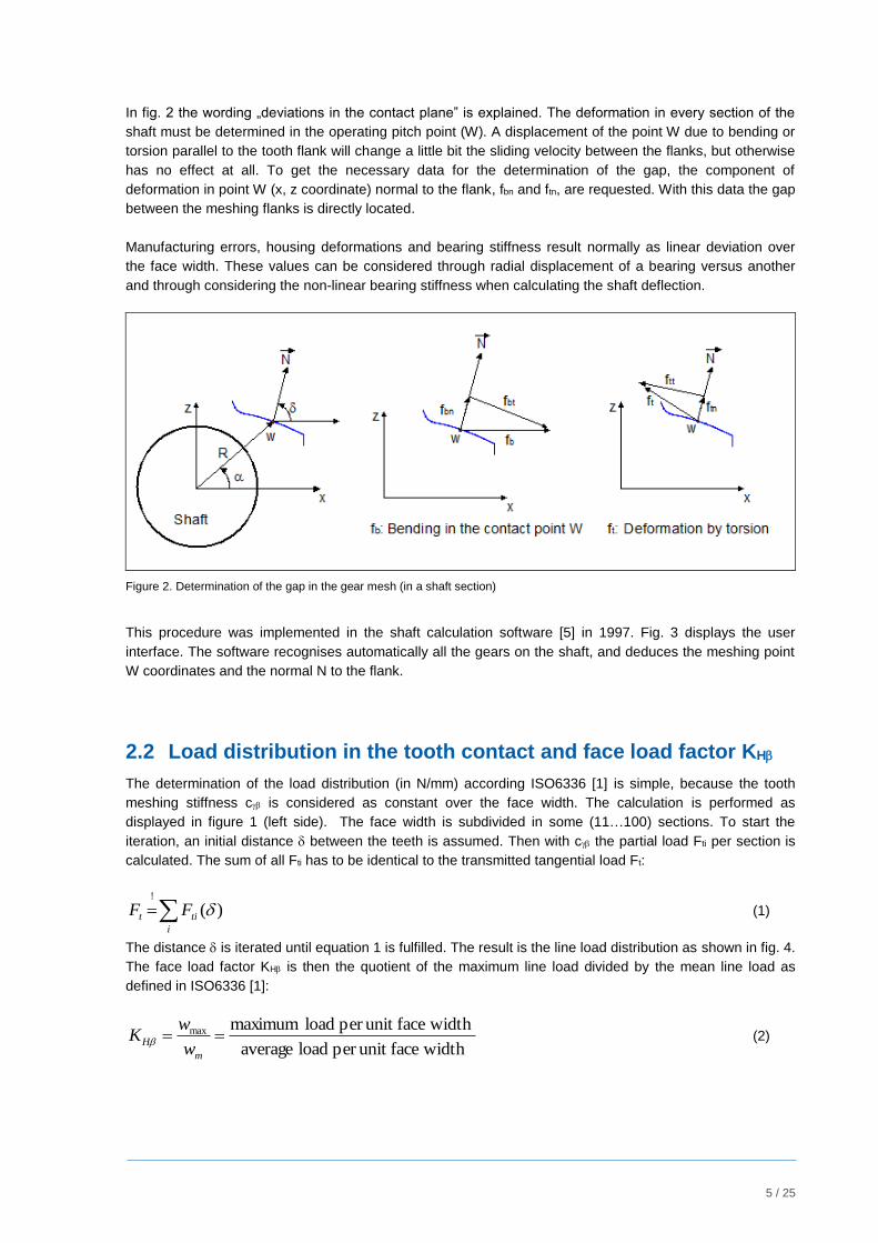
In fig. 2 the wording „deviations in the contact plane” is explained. The deformation in every section of the
shaft must be determined in the operating pitch point (W). A displacement of the point W due to bending or
torsion parallel to the tooth flank will change a little bit the sliding velocity between the flanks, but otherwise
has no effect at all. To get the necessary data for the determination of the gap, the component of
deformation in point W (x, z coordinate) normal to the flank, fbn and ftn, are requested. With this data the gap
between the meshing flanks is directly located.
Manufacturing errors, housing deformations and bearing stiffness result normally as linear deviation over
the face width. These values can be considered through radial displacement of a bearing versus another
and through considering the non-linear bearing stiffness when calculating the shaft deflection.
Figure 2. Determination of the gap in the gear mesh (in a shaft section)
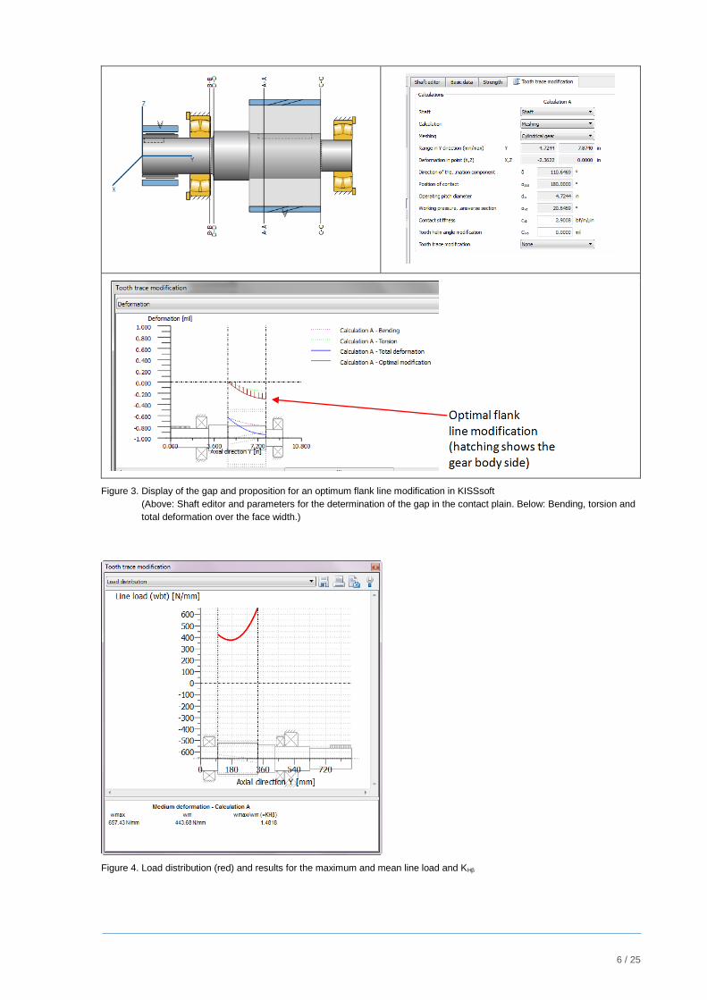
This procedure was implemented in the shaft calculation software [5] in 1997. Fig. 3 displays the user
interface. The software recognises automatically all the gears on the shaft, and deduces the meshing point
W coordinates and the normal N to the flank.
2.2 Load distribution in the tooth contact and face load factor KH
The determination of the load distribution (in N/mm) according ISO6336 [1] is simple, because the tooth
meshing stiffness c is considered as constant over the face width. The calculation is performed as
displayed in figure 1 (left side). The face width is subdivided in some (11…100) sections. To start the
iteration, an initial distance between the teeth is assumed. Then with c the partial load Fti per section is
calculated. The sum of all Fti has to be identical to the transmitted tangential load Ft:
i
tit FF )(!
(1)
The distance is iterated until equation 1 is fulfilled. The result is the line load distribution as shown in fig. 4.
The face load factor KH is then the quotient of the maximum line load divided by the mean line load as
defined in ISO6336 [1]:
widthfaceunit per load average
width faceunit per load maximummax m
Hw
wK (2)
6 / 25
Figure 3. Display of the gap and proposition for an optimum flank line modification in KISSsoft
(Above: Shaft editor and parameters for the determination of the gap in the contact plain. Below: Bending, torsion and
total deformation over the face width.)
Figure 4. Load distribution (red) and results for the maximum and mean line load and KH
7 / 25
2.3 Optimization of the load distribution with adapted flank line modifications
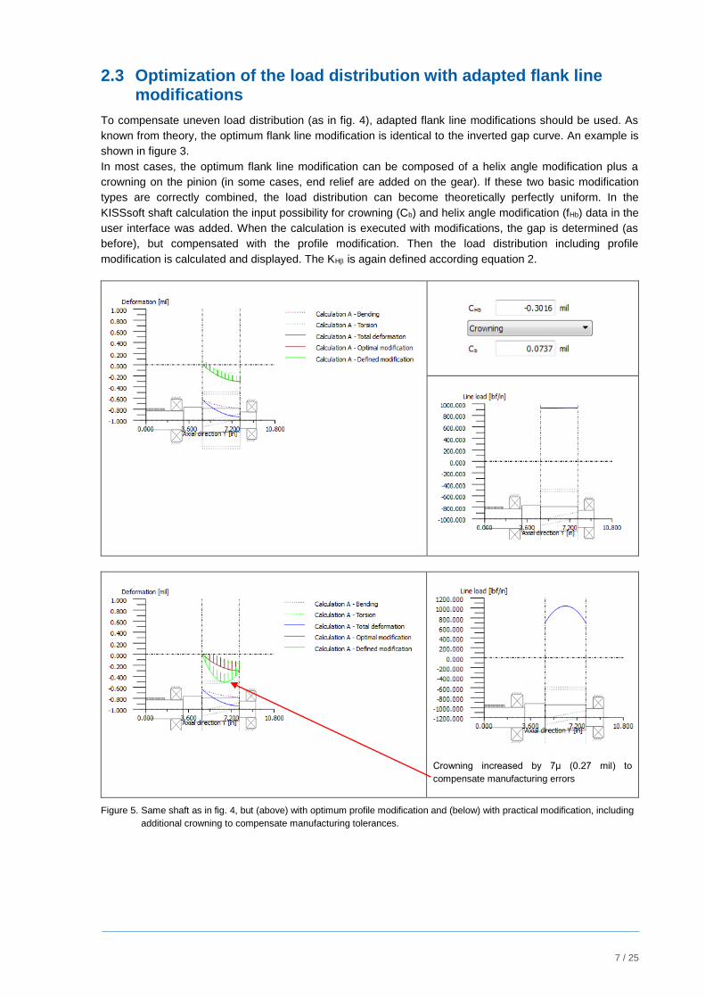
To compensate uneven load distribution (as in fig. 4), adapted flank line modifications should be used. As
known from theory, the optimum flank line modification is identical to the inverted gap curve. An example is
shown in figure 3.
In most cases, the optimum flank line modification can be composed of a helix angle modification plus a
crowning on the pinion (in some cases, end relief are added on the gear). If these two basic modification
types are correctly combined, the load distribution can become theoretically perfectly uniform. In the
KISSsoft shaft calculation the input possibility for crowning (Cb) and helix angle modification (fHb) data in the
user interface was added. When the calculation is executed with modifications, the gap is determined (as
before), but compensated with the profile modification. Then the load distribution including profile
modification is calculated and displayed. The KH is again defined according equation 2.
Crowning increased by 7μ (0.27 mil) to
compensate manufacturing errors
Figure 5. Same shaft as in fig. 4, but (above) with optimum profile modification and (below) with practical modification, including
additional crowning to compensate manufacturing tolerances.
8 / 25
In the example of fig. 4, a crowning Cb=1.8 μm (0.07 mil) and a helix angle modification fHb=-7.6 μm
(-0.30 mil) would give a uniform load distribution (fig.5). With such a modification, the face load factor KH is
theoretically KH1.0. However, for a real gear, not only the deformation should be compensated. Due to
manufacturing errors, the gear will have a flank line error, which is in a predefined tolerance band
depending on the tolerance class. Manufacturing errors are stochastic; they may reduce or increase the
gap. Good design practice is to get the maximum load in the center of the face width; thus the only way to
compensate manufacturing errors is to increase the crowning (or to apply additional end relief). The
proposition in ISO6336-1 [1], annex B, is to increase the crowning by 0.75…1.0 * fH (helix slope deviation).
If this technique is used, which is recommended, then the face load factor will theoretically be higher than
1.00 again; but will provide a better practical design, less susceptible to poor load distribution due to
manufacturing errors.
3 Load distribution and face load factor determination based on ISO6336-1, annex E
The basic idea in ISO6336-1, Annex E, is exactly the same as described in the previous chapter, but
applied on both gears in the gear pair, thus much more general. The method is, as will be shown with some
examples in this paper, a very useful calculation method.
Compared with the simpler algorithm described in the previous chapter, ISO6336-1, Annex E, proposes
some very important improvements:
The gear mesh (pinion and gear shaft are both taken into account) is considered.
The load distribution over the face width is iterated: The area of the gear teeth is split into ten equal
sections. The first calculation run is performed using uniform load distribution to get the shaft
deformation. From the initial gap, an uneven load distribution is calculated. This new load
distribution is then used to calculate a new shaft deformation. This iteration process is continued
until the newly calculated gaps differ from the previous ones by only a small amount. Usually only a
few, 2 or 3, iterations are required to get an acceptable error (less than 3.0 μm change in gaps
calculated).
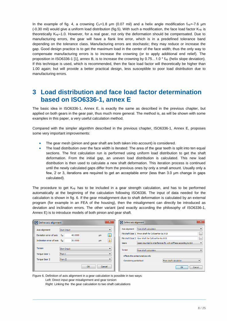
The procedure to get KH has to be included in a gear strength calculation, and has to be performed
automatically at the beginning of the calculation following ISO6336. The input of data needed for the
calculation is shown in fig. 6. If the gear misalignment due to shaft deformation is calculated by an external
program (for example in an FEA of the housing), then the misalignment can directly be introduced as
deviation and inclination errors. The other variant (and exactly according the philosophy of ISO6336-1,
Annex E) is to introduce models of both pinion and gear shaft.
Figure 6. Definition of axis alignment in a gear calculation is possible in two ways:
Left: Direct input gear misalignment and gear torsion
Right: Linking the the gear calculation to two shaft calculations
9 / 25
3.1 Improvement of the algorithm as proposed in ISO6336-1, Annex E
The algorithm as proposed in ISO6336-1, Annex E, has some restrictions, which should be overruled, to
increase the precision of the results.
a) Shear deformations of the shaft are not included. This is not critical on long shafts, but can be
important on short shafts with large diameter. Therefore it is recommended to include shear
deflection in the bending calculation.
b) Iteration is continued until less than 3.0 μm change in gap calculated is obtained. This is a good
criteria for big gears, but not for gear sets with module smaller than 2.0 mm (DP smaller than 12.7).
In KISSsoft, the criteria to get more accurate results for any dimension of the shaft; the iteration
stops, if the gap change is less than 0.1 %.
c) When calculating shaft deflections, the area of the gear teeth is broken into ten equal sections. If
short end relief or similar fast changing flank line modifications are applied, then the effect of the
modification cannot be simulated with only ten sections. In KISSsoft, this value is increased to 41
sections (and more if requested).
d) The tooth stiffness is called ‘stiffness constant‘ in N/mm/ with symbol cm; but there is no reference
to this symbol in other parts of ISO6336. In principal the stiffness used should be exactly the
stiffness c, as defined in ISO6336-1, chapter 9. In AGMA927 an additional indication is given,
claiming that cm is ~11 N/mm/ for steel gears. 11 N/mm/ is very low; typically the stiffness
calculated accurately for a wide range of gears is 16-24 N/mm/. A low stiffness value (such as 11
N/mm/) will result in a low KH -value; therefore the assumption of 11 N/mm/ is NOT on the safe
side! We decided to provide the choice to the calculation engineer, if choosing the stiffness c as in
ISO, or 11 as in AGMA, or any other value calculated with more precise algorithm.
e) For the calculation of the shaft bending, the equivalent outside diameter of the teeth is halfway
between tip diameter and root diameter. This is correct for pinion shafts. For gears using a shrink-
fit, the equivalent outside diameter is less. ISO6336 proposes in chapter 5 to use a diameter in the
middle between hub diameter and bore. Depending on the shrink-fit the resulting system
stiffnessmay vary, therefore this is a difficult topic to handle.
3.2 Application of the algorithm
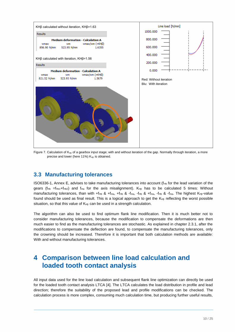
With these additional improvements, the algorithm is highly practical and the yields accurate results. As
shown in fig. 7, the iteration of the gap is necessary to get more precise results.
If it is possible, as in the modern shaft calculation, to introduce bearings with stiffness calculated e.g.
according ISO 16281 [7] (based on the inner bearing geometry and operating clearance), the results are still
more accurate. But even, if all these improvements are included, the method is still relatively simple –
compared with a contact analysis; and therefore the calculation time very short.
The today trend in gear software is to use system programs, able to handle a complete power transmission
chain. In these applications (fig. 7), all data needed to perform a load distribution analysis according
ISO6336-1, annex E, are available (the shafts and connecting gear set); therefore to execute such a
calculation does not need any additional input from user side, which makes the task easier.
10 / 25
KHβ calculated without iteration, KHβ=1.63
KHβ calculated with iteration, KHβ=1.56
Red: Without iteration
Blu: With iteration
Figure 7. Calculation of KH of a gearbox input stage; with and without iteration of the gap. Normally through iteration, a more
precise and lower (here 11%) KH is obtained.
3.3 Manufacturing tolerances
ISO6336-1, Annex E, advises to take manufacturing tolerances into account (fHb for the lead variation of the
gears (fHb =fHb1+fHb2) and fma for the axis misalignment). KH has to be calculated 5 times: Without
manufacturing tolerances, than with +fHb & +fma, +fHb & -fma, -fHb & +fma, -fHb & -fma. The highest KH-value
found should be used as final result. This is a logical approach to get the KH reflecting the worst possible
situation, so that this value of KH can be used in a strength calculation.
The algorithm can also be used to find optimum flank line modification. Then it is much better not to
consider manufacturing tolerances, because the modification to compensate the deformations are then
much easier to find as the manufacturing tolerances are stochastic. As explained in chapter 2.3.1, after the
modifications to compensate the deflection are found, to compensate the manufacturing tolerances, only
the crowning should be increased. Therefore it is important that both calculation methods are available:
With and without manufacturing tolerances.
4 Comparison between line load calculation and loaded tooth contact analysis
All input data used for the line load calculation and subsequent flank line optimization can directly be used
for the loaded tooth contact analysis LTCA [4]. The LTCA calculates the load distribution in profile and lead
direction; therefore the suitability of the proposed lead and profile modifications can be checked. The
calculation process is more complex, consuming much calculation time, but producing further useful results,
11 / 25
such as the transmission error for noise optimization or the lubrication film thickness for the micropitting risk
determination [11].
It is therefore logical, that the outcome of the load distribution as calculated according ISO6336-1, Annex E,
is not identical to the LTCA results; but when the line load in the area of the operating pitch diameter is
compared, the results are very close. Simply put, ISO6336-1, Annex E, performs a one-dimensional contact
analysis, considering only the situation in the operating pitch point of every section. The result is a 2D
graphic, showing the line load distribution over the face width, which is easier to understand than the 3D
colored contact pattern results (fig. 8) from the two dimensional LTCA. A difference, which has to be
remembered when using helical gears or deep tooth profile gears, is that the line load calculated following
ISO6336-1, Annex E, tends to yield higher KHβ values, than the load as calculated by contact analysis. The
differences depend on the transverse overlap ratio and the contact ratio , because ISO6336-1, Annex
E, does the calculation supposing = + = 1 (fig. 8). Thus the absolute value issued is not precise in
this case, but the course of the curve is accurate; thus giving a correct value for KH.
Thus a good design technique is: First use ISO6336-1, Annex E, to find near to optimum flank line
modification, then use contact analysis to find the optimum flank and profile modification combination.
Experience from engineering projects shows that the results of ISO6336-1, Annex E, are in line with the
results of the LTCA. So the outcome of the algorithm as defined in ISO6336-1, Annex E, is typically very
satisfying.
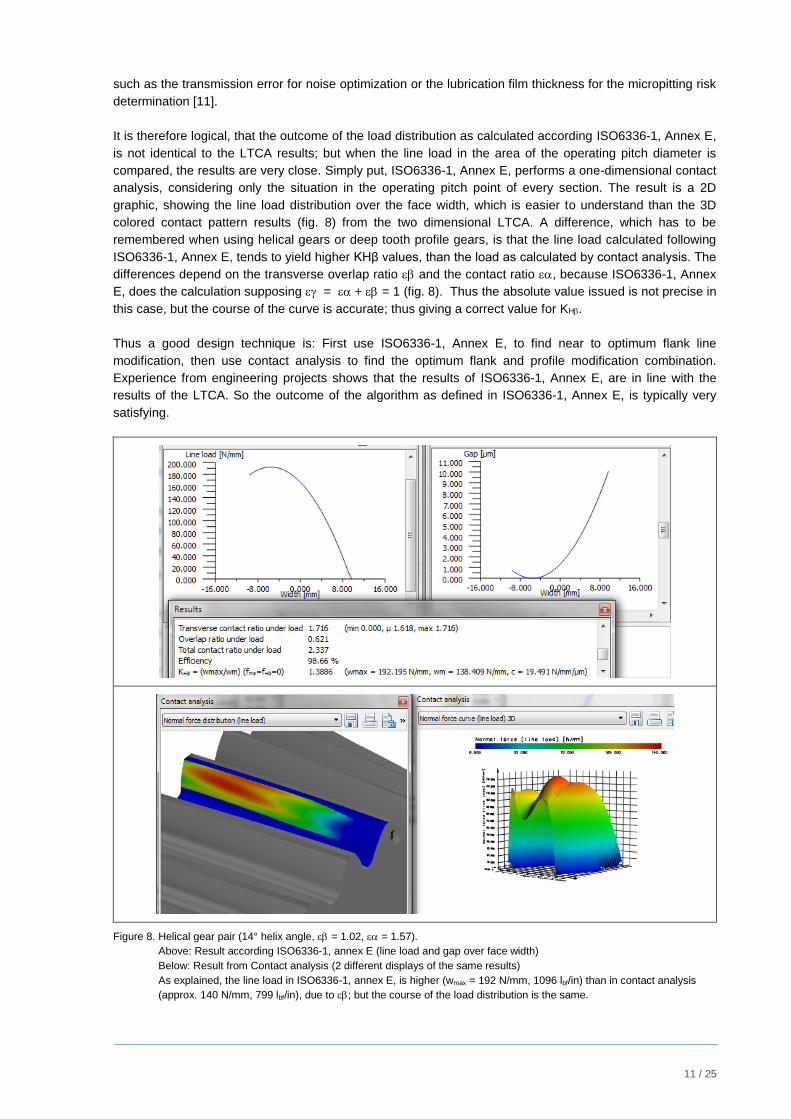
Figure 8. Helical gear pair (14° helix angle, = 1.02, = 1.57).
Above: Result according ISO6336-1, annex E (line load and gap over face width)
Below: Result from Contact analysis (2 different displays of the same results)
As explained, the line load in ISO6336-1, annex E, is higher (wmax = 192 N/mm, 1096 lbf/in) than in contact analysis
(approx. 140 N/mm, 799 lbf/in), due to ; but the course of the load distribution is the same.
12 / 25
5 Application: Optimization of flank line modifications with load spectrum
5.1 Flank line modifications for nominal torque (no duty cycles)
A combination of flank line and profile modifications is a must in today gear design. Flank line modifications
are intended to get a uniform load distribution over the face width to improve the lifetime of the gear. A first
selection of modifications is typically accomplished based on experience; to verify that the modifications
lead to the requested results, a LTCA analysis may be used, any optimization is however time consuming.
For a gear pair with a given load, the fastest manner to design the optimum flank line is to use the simple
method as described in chapter 2, separately for pinion and gear (using only the shaft calculation). With
that, the optimum flank line modification for each gear is found easily. Clearly, if desired, the total
modification can than also be applied only on one of the gears. Then the proposition has to be checked,
using the ISO6336-1, Annex E, method with the gear mesh. In most cases, this simple approach gives
directly very good results with KH lower than 1.10; hence there is often no need for further optimization
steps.
5.2 Flank line modifications for applications with load spectrum
For gears subjected to a load spectrum, the approach for an optimum flank line modification is much more
complicated: For which of the duty cycle elements should the modification be optimized? This is in many
cases very difficult to know. If the modification is optimum for the element with the highest load (having
normally a short operating time), then often the other elements (having higher operating time) get an
increase of KH, so far that the overall lifetime of the gear pair may decrease!
As a first step the ISO6336-1, Annex E, method was combined with the calculation of the lifetime with duty
cycles, as described in ISO6336-6 [8]. For every bin of the load spectrum, the deformation of the shafts with
the torque of the element is recalculated and the individual KH is derived. Then the ‘normal’ calculation
approach is executed.
In a second step this procedure is combined with an optimization tool, which for a given gear pair varies
different combinations of flank line modifications. The best way to explain the course of action is to describe
a recent project example.
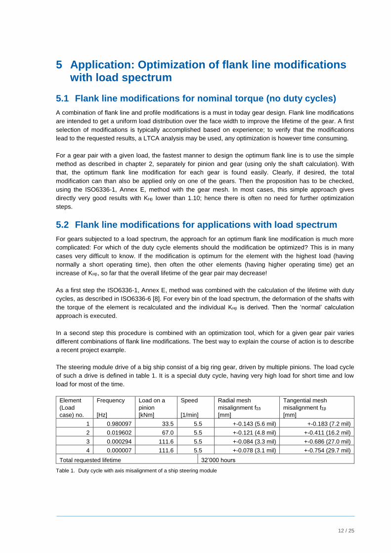
The steering module drive of a big ship consist of a big ring gear, driven by multiple pinions. The load cycle
of such a drive is defined in table 1. It is a special duty cycle, having very high load for short time and low
load for most of the time.
Element
(Load
case) no.
Frequency
[Hz]
Load on a
pinion
[kNm]
Speed
[1/min]
Radial mesh
misalignment fΣδ
[mm]
Tangential mesh
misalignment fΣβ
[mm]
1 0.980097 33.5 5.5 +-0.143 (5.6 mil) +-0.183 (7.2 mil)
2 0.019602 67.0 5.5 +-0.121 (4.8 mil) +-0.411 (16.2 mil)
3 0.000294 111.6 5.5 +-0.084 (3.3 mil) +-0.686 (27.0 mil)
4 0.000007 111.6 5.5 +-0.078 (3.1 mil) +-0.754 (29.7 mil)
Total requested lifetime 32’000 hours
Table 1. Duty cycle with axis misalignment of a ship steering module
13 / 25
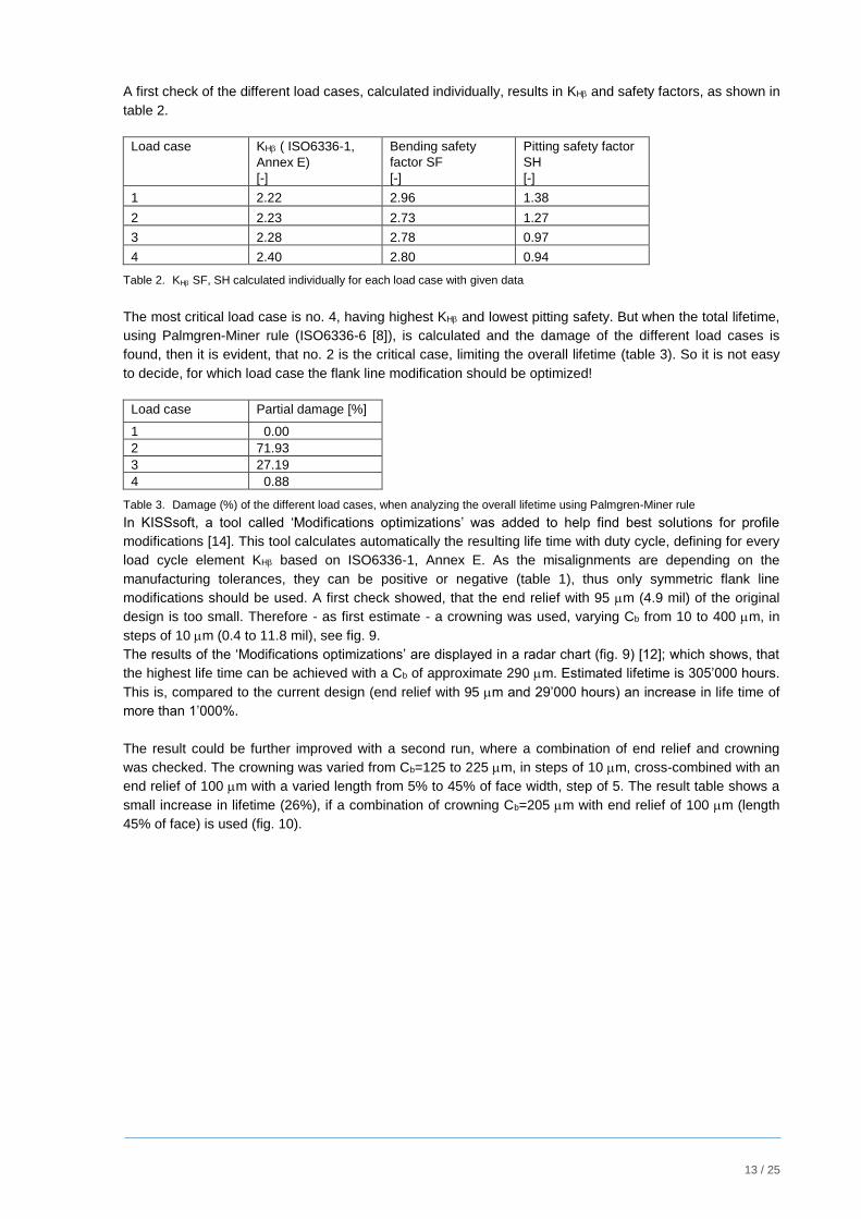
A first check of the different load cases, calculated individually, results in KH and safety factors, as shown in
table 2.
Load case KH ( ISO6336-1,
Annex E)
[-]
Bending safety
factor SF
[-]
Pitting safety factor
SH
[-]
1 2.22 2.96 1.38
2 2.23 2.73 1.27
3 2.28 2.78 0.97
4 2.40 2.80 0.94
Table 2. KH SF, SH calculated individually for each load case with given data
The most critical load case is no. 4, having highest KH and lowest pitting safety. But when the total lifetime,
using Palmgren-Miner rule (ISO6336-6 [8]), is calculated and the damage of the different load cases is
found, then it is evident, that no. 2 is the critical case, limiting the overall lifetime (table 3). So it is not easy
to decide, for which load case the flank line modification should be optimized!
Load case Partial damage [%]
1 0.00
2 71.93
3 27.19
4 0.88
Table 3. Damage (%) of the different load cases, when analyzing the overall lifetime using Palmgren-Miner rule
In KISSsoft, a tool called ‘Modifications optimizations’ was added to help find best solutions for profile
modifications [14]. This tool calculates automatically the resulting life time with duty cycle, defining for every
load cycle element KH based on ISO6336-1, Annex E. As the misalignments are depending on the
manufacturing tolerances, they can be positive or negative (table 1), thus only symmetric flank line
modifications should be used. A first check showed, that the end relief with 95 m (4.9 mil) of the original
design is too small. Therefore - as first estimate - a crowning was used, varying Cb from 10 to 400 m, in
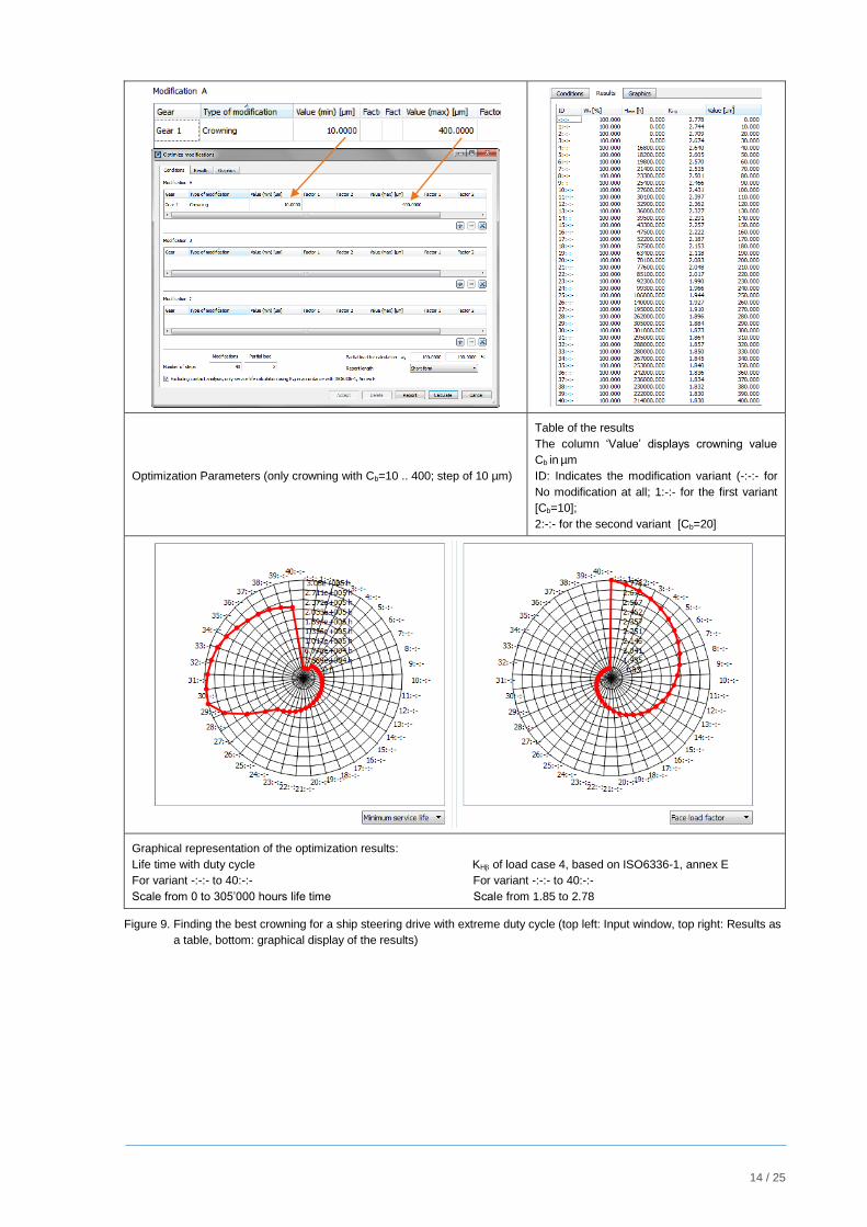
steps of 10 m (0.4 to 11.8 mil), see fig. 9.
The results of the ‘Modifications optimizations’ are displayed in a radar chart (fig. 9) [12]; which shows, that
the highest life time can be achieved with a Cb of approximate 290 m. Estimated lifetime is 305’000 hours.
This is, compared to the current design (end relief with 95 m and 29’000 hours) an increase in life time of
more than 1’000%.
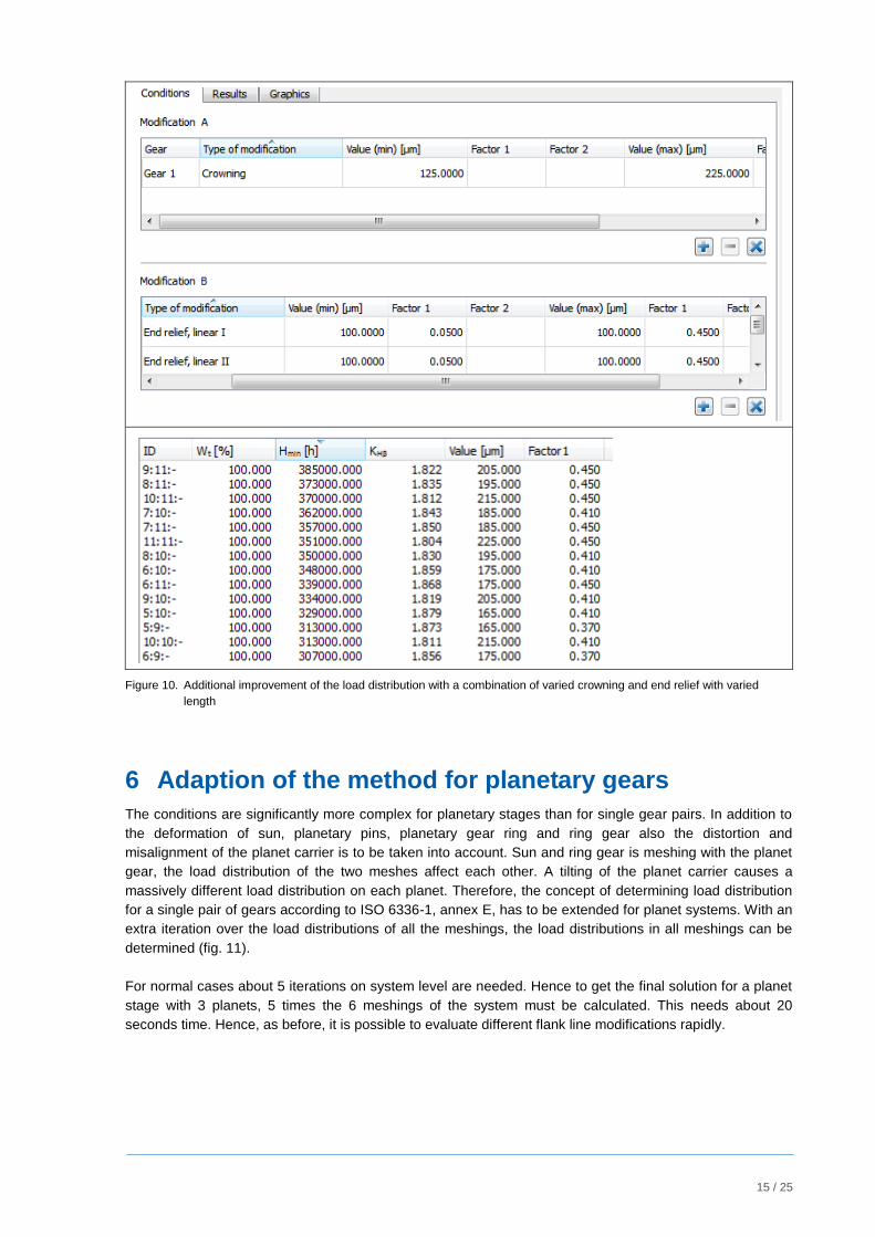
The result could be further improved with a second run, where a combination of end relief and crowning
was checked. The crowning was varied from Cb=125 to 225 m, in steps of 10 m, cross-combined with an
end relief of 100 m with a varied length from 5% to 45% of face width, step of 5. The result table shows a
small increase in lifetime (26%), if a combination of crowning Cb=205 m with end relief of 100 m (length
45% of face) is used (fig. 10).
14 / 25
Optimization Parameters (only crowning with Cb=10 .. 400; step of 10 µm)
Table of the results
The column ‘Value’ displays crowning value
Cb in µm
ID: Indicates the modification variant (-:-:- for
No modification at all; 1:-:- for the first variant
[Cb=10];
2:-:- for the second variant [Cb=20]
Graphical representation of the optimization results:
Life time with duty cycle KH of load case 4, based on ISO6336-1, annex E
For variant -:-:- to 40:-:- For variant -:-:- to 40:-:-
Scale from 0 to 305’000 hours life time Scale from 1.85 to 2.78
Figure 9. Finding the best crowning for a ship steering drive with extreme duty cycle (top left: Input window, top right: Results as
a table, bottom: graphical display of the results)
15 / 25
Figure 10. Additional improvement of the load distribution with a combination of varied crowning and end relief with varied
length
6 Adaption of the method for planetary gears
The conditions are significantly more complex for planetary stages than for single gear pairs. In addition to
the deformation of sun, planetary pins, planetary gear ring and ring gear also the distortion and
misalignment of the planet carrier is to be taken into account. Sun and ring gear is meshing with the planet
gear, the load distribution of the two meshes affect each other. A tilting of the planet carrier causes a
massively different load distribution on each planet. Therefore, the concept of determining load distribution
for a single pair of gears according to ISO 6336-1, annex E, has to be extended for planet systems. With an
extra iteration over the load distributions of all the meshings, the load distributions in all meshings can be
determined (fig. 11).
For normal cases about 5 iterations on system level are needed. Hence to get the final solution for a planet
stage with 3 planets, 5 times the 6 meshings of the system must be calculated. This needs about 20
seconds time. Hence, as before, it is possible to evaluate different flank line modifications rapidly.
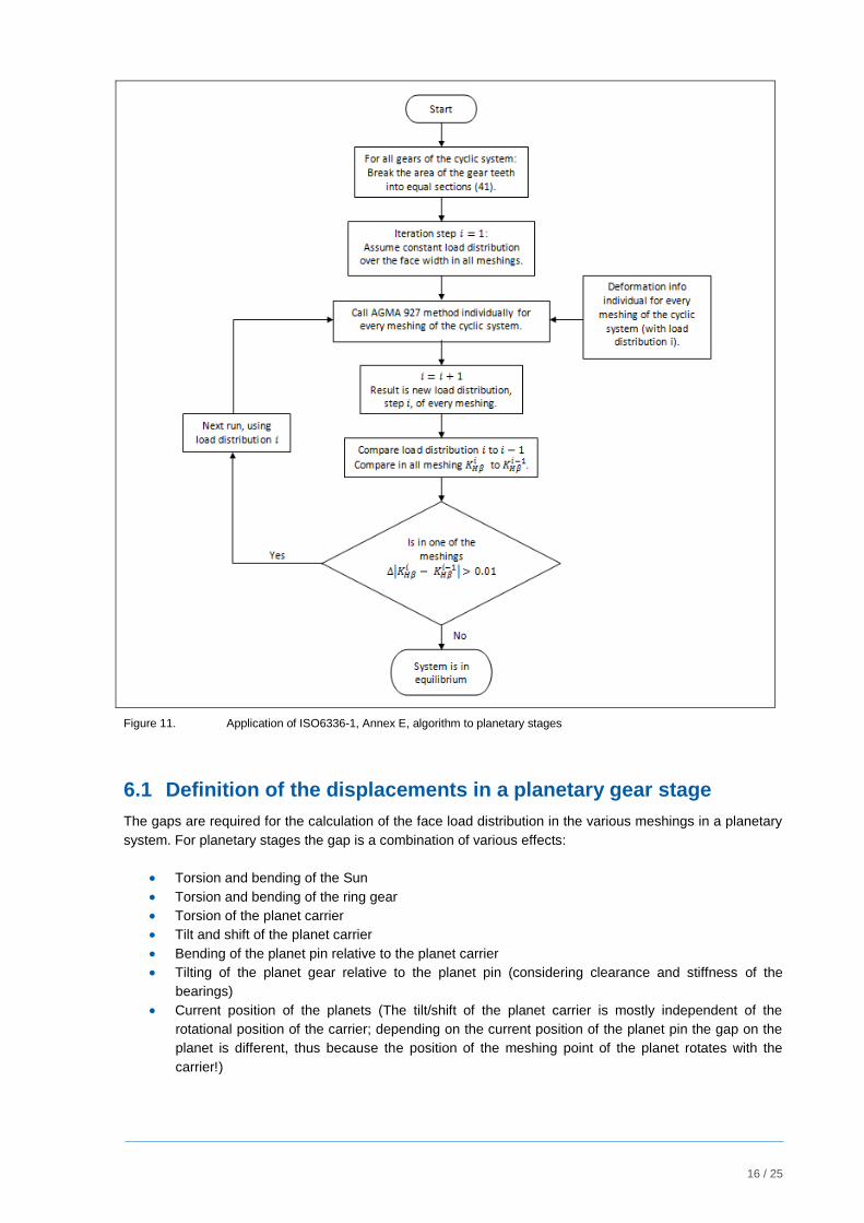
16 / 25
Figure 11. Application of ISO6336-1, Annex E, algorithm to planetary stages
6.1 Definition of the displacements in a planetary gear stage
The gaps are required for the calculation of the face load distribution in the various meshings in a planetary
system. For planetary stages the gap is a combination of various effects:
Torsion and bending of the Sun
Torsion and bending of the ring gear
Torsion of the planet carrier
Tilt and shift of the planet carrier
Bending of the planet pin relative to the planet carrier
Tilting of the planet gear relative to the planet pin (considering clearance and stiffness of the
bearings)
Current position of the planets (The tilt/shift of the planet carrier is mostly independent of the
rotational position of the carrier; depending on the current position of the planet pin the gap on the
planet is different, thus because the position of the meshing point of the planet rotates with the
carrier!)
17 / 25
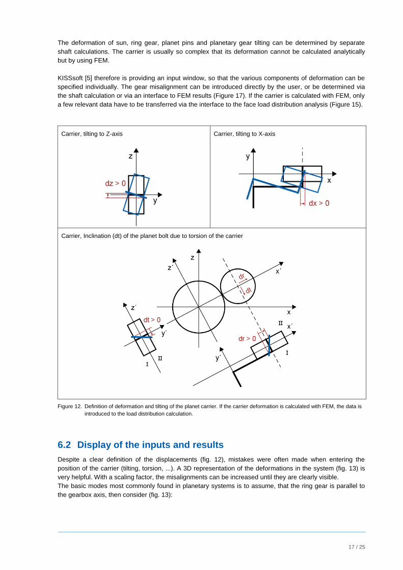
The deformation of sun, ring gear, planet pins and planetary gear tilting can be determined by separate
shaft calculations. The carrier is usually so complex that its deformation cannot be calculated analytically
but by using FEM.
KISSsoft [5] therefore is providing an input window, so that the various components of deformation can be
specified individually. The gear misalignment can be introduced directly by the user, or be determined via
the shaft calculation or via an interface to FEM results (Figure 17). If the carrier is calculated with FEM, only
a few relevant data have to be transferred via the interface to the face load distribution analysis (Figure 15).
Carrier, tilting to Z-axis
Carrier, tilting to X-axis
Carrier, Inclination (dt) of the planet bolt due to torsion of the carrier
Figure 12. Definition of deformation and tilting of the planet carrier. If the carrier deformation is calculated with FEM, the data is
introduced to the load distribution calculation.
6.2 Display of the inputs and results
Despite a clear definition of the displacements (fig. 12), mistakes were often made when entering the
position of the carrier (tilting, torsion, ...). A 3D representation of the deformations in the system (fig. 13) is
very helpful. With a scaling factor, the misalignments can be increased until they are clearly visible.
The basic modes most commonly found in planetary systems is to assume, that the ring gear is parallel to
the gearbox axis, then consider (fig. 13):
18 / 25
1) Torsional wind up of planetary carrier
2) In case of helical gears, the planet tilts, leading to an inclination error
3) Tilting of planetary carrier in two axis due to main shaft bending
4) Tilting of sun gear in two axis
Effect 1) and 2) are (assuming that the torque direction does not change) always in the same direction and
may be compensated by means of a helix angle correction.
Effect 3) and 4) can be in any direction, hence, they cannot be compensated for by means of a helix angle
correction and a crowning is required on the planets.
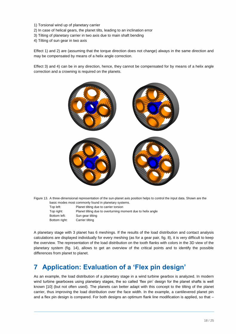
Figure 13. A three-dimensional representation of the sun-planet axis position helps to control the input data. Shown are the
basic modes most commonly found in planetary systems.
Top left: Planet tilting due to carrier torsion
Top right: Planet tilting due to overturning moment due to helix angle
Bottom left: Sun gear tilting
Bottom right: Carrier tilting
A planetary stage with 3 planet has 6 meshings. If the results of the load distribution and contact analysis
calculations are displayed individually for every meshing (as for a gear pair, fig. 8), it is very difficult to keep
the overview. The representation of the load distribution on the tooth flanks with colors in the 3D view of the
planetary system (fig. 14), allows to get an overview of the critical points and to identify the possible
differences from planet to planet.
7 Application: Evaluation of a ‘Flex pin design’
As an example, the load distribution of a planetary stage in a wind turbine gearbox is analyzed. In modern
wind turbine gearboxes using planetary stages, the so called ‘flex pin’ design for the planet shafts is well
known [10] (but not often used). The planets can better adapt with this concept to the tilting of the planet
carrier, thus improving the load distribution over the face width. In the example, a cantilevered planet pin
and a flex pin design is compared. For both designs an optimum flank line modification is applied, so that –
19 / 25
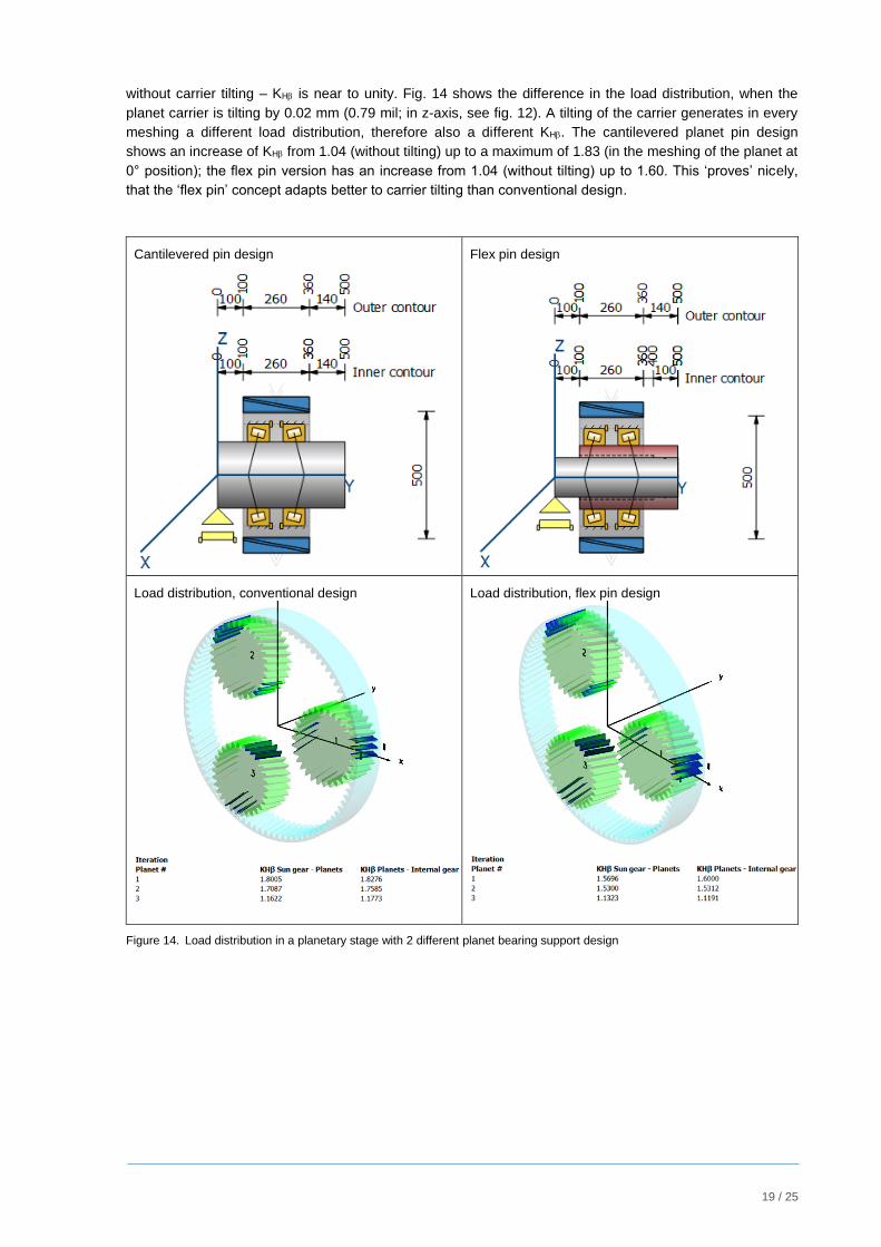
without carrier tilting – KH is near to unity. Fig. 14 shows the difference in the load distribution, when the
planet carrier is tilting by 0.02 mm (0.79 mil; in z-axis, see fig. 12). A tilting of the carrier generates in every
meshing a different load distribution, therefore also a different KH. The cantilevered planet pin design
shows an increase of KH from 1.04 (without tilting) up to a maximum of 1.83 (in the meshing of the planet at
0° position); the flex pin version has an increase from 1.04 (without tilting) up to 1.60. This ‘proves’ nicely,
that the ‘flex pin’ concept adapts better to carrier tilting than conventional design.
Cantilevered pin design
Flex pin design
Load distribution, conventional design
Load distribution, flex pin design
Figure 14. Load distribution in a planetary stage with 2 different planet bearing support design
20 / 25
8 Influence of planet carrier torsion when using ISO6336-1, Annex E, method
A most typical planetary system consists of sun, planet, planet pin, carrier and ring gear. Modelling the
complete system in a FEM model is very complicated, and the time needed for an accurate analysis is very
high. But most elements contained in a planetary system are rotation symmetric, can therefore be
calculated as shafts/bearings elements. Normally only the planet carrier has a contour which requires a
FEM analysis; so a combination by an interface between the FEM carrier analysis and the load distribution
analysis of the planetary stage using ISO6336-1, Annex E, method is a fast and very precise procedure.
8.1 Application: Wind turbine gear box
This method is used in the design process of wind turbine gear box consisting of two planetary stages (with
4 planets in the low speed stage) and one high speed helical stage (fig. 18, there, showing two gearboxes
in a testing arrangement). The design torque at the rotor shaft is 2.3 MNm. The planet carrier, calculated by
FEM (Abaqus [12]), was modeled in 4 different variants (without planet pin, as one piece with the pin, pin
mounted by press fit with low and high interference; fig. 16). The aim was to get an information if the press
fit of the pin in the carrier has an important influence on the load distribution.
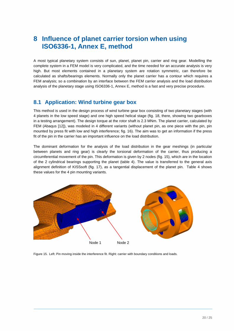
The dominant deformation for the analysis of the load distribution in the gear meshings (in particular
between planets and ring gear) is clearly the torsional deformation of the carrier, thus producing a
circumferential movement of the pin. This deformation is given by 2 nodes (fig. 15), which are in the location
of the 2 cylindrical bearings supporting the planet (table 4). The value is transferred to the general axis
alignment definition of KISSsoft (fig. 17), as a tangential displacement of the planet pin. Table 4 shows
these values for the 4 pin mounting variants.
Node 1 Node 2
Figure 15. Left: Pin moving inside the interference fit. Right: carrier with boundary conditions and loads.
21 / 25
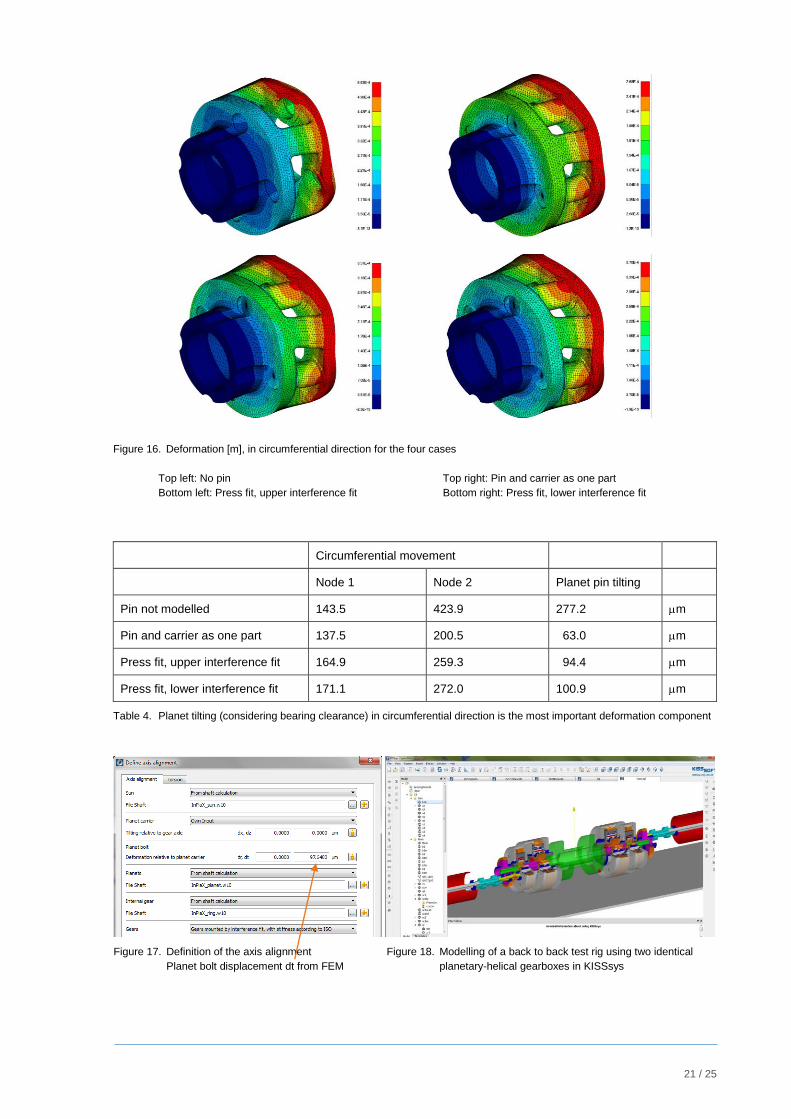
Figure 16. Deformation [m], in circumferential direction for the four cases
Top left: No pin Top right: Pin and carrier as one part
Bottom left: Press fit, upper interference fit Bottom right: Press fit, lower interference fit
Circumferential movement
Node 1 Node 2 Planet pin tilting
Pin not modelled 143.5 423.9 277.2 m
Pin and carrier as one part 137.5 200.5 63.0 m
Press fit, upper interference fit 164.9 259.3 94.4 m
Press fit, lower interference fit 171.1 272.0 100.9 m
Table 4. Planet tilting (considering bearing clearance) in circumferential direction is the most important deformation component
Figure 17. Definition of the axis alignment
Planet bolt displacement dt from FEM
Figure 18. Modelling of a back to back test rig using two identical
planetary-helical gearboxes in KISSsys
22 / 25
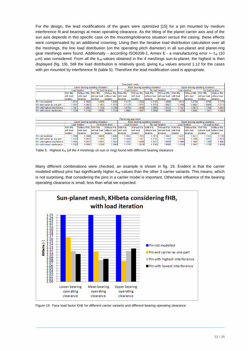
For the design, the lead modifications of the gears were optimized [15] for a pin mounted by medium
interference fit and bearings at mean operating clearance. As the tilting of the planet carrier axis and of the
sun axis depends in this specific case on the mounting/tolerance situation versus the casing, these effects
were compensated by an additional crowning. Using then the iterative load distribution calculation over all
the meshings, the line load distribution (on the operating pitch diameter) in all sun-planet and planet-ring
gear meshings were found. Additionally – according ISO6336-1, Annex E - a manufacturing error +- fHβ (10
m) was considered. From all the KHβ-values obtained in the 4 meshings sun-to-planet, the highest is then
displayed (fig. 19). Still the load distribution is relatively good, giving KHβ values around 1.12 for the cases
with pin mounted by interference fit (table 5). Therefore the lead modification used is appropriate.
Table 5. Highest KHβ (of the 4 meshings on sun or ring) found with different bearing clearance
Many different combinations were checked, an example is shown in fig. 19. Evident is that the carrier
modeled without pins has significantly higher KHβ-values than the other 3 carrier variants. This means, which
is not surprising, that considering the pins in a carrier model is important. Otherwise influence of the bearing
operating clearance is small, less than what we expected.
Figure 19. Face load factor KH for different carrier variants and different bearing operating clearance

23 / 25
8.2 Combination with contact analysis: Sun gear root Strain – calculated and measured
The iterative load distribution calculation over all the meshings is also integrated in the contact analysis
under load (LTCA). This is clearly a more time consuming calculation process, but provides load distribution
and stresses over the contact surface of all meshings. The wind turbine prototype had to be checked on the
test rig, using a back-to-back configuration (fig. 18). A check of the carrier position on the test rig showed,
that – due to mounting inaccuracy and bending of the main shaft – n
vertical direction. This effect has to be added to the definition of the shaft alignments (fig. 17) and is
considered in the calculation. This tilting is the main reason why the stress distributions over the face width
in the 4 meshings of the sun are quite different (fig. 20).
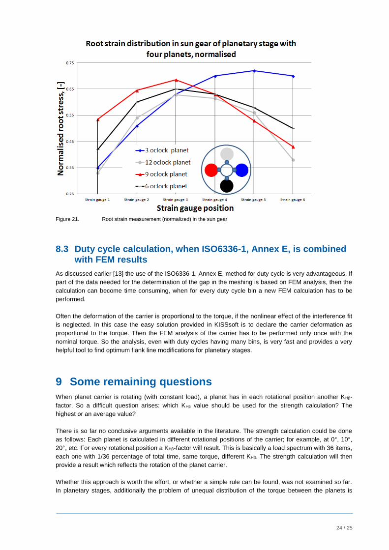
To check the results the root stress on the sun was measured on four teeth, on 6 positions along the face
width per tooth. Fig. 21 shows the stress measured in the root area of a tooth of the sun, when in contact
with the different planets. Compared with the results obtained through contact analysis with iteration of the
load distribution in the planetary system, the measurements are in good agreement.
Meshing sun-planet no.1 at 3 o’clock No.2 at 6 o’clock
No.3 at 9 o’clock No.4 at 12 o’clock
Figure 20. Sun gear, root stress distribution, for all four positions on the sun gear
24 / 25
Figure 21. Root strain measurement (normalized) in the sun gear
8.3 Duty cycle calculation, when ISO6336-1, Annex E, is combined with FEM results
As discussed earlier [13] the use of the ISO6336-1, Annex E, method for duty cycle is very advantageous. If
part of the data needed for the determination of the gap in the meshing is based on FEM analysis, then the
calculation can become time consuming, when for every duty cycle bin a new FEM calculation has to be
performed.
Often the deformation of the carrier is proportional to the torque, if the nonlinear effect of the interference fit
is neglected. In this case the easy solution provided in KISSsoft is to declare the carrier deformation as
proportional to the torque. Then the FEM analysis of the carrier has to be performed only once with the
nominal torque. So the analysis, even with duty cycles having many bins, is very fast and provides a very
helpful tool to find optimum flank line modifications for planetary stages.
9 Some remaining questions
When planet carrier is rotating (with constant load), a planet has in each rotational position another KHβ-
factor. So a difficult question arises: which KHβ value should be used for the strength calculation? The
highest or an average value?
There is so far no conclusive arguments available in the literature. The strength calculation could be done
as follows: Each planet is calculated in different rotational positions of the carrier; for example, at 0°, 10°,
20°, etc. For every rotational position a KHβ-factor will result. This is basically a load spectrum with 36 items,
each one with 1/36 percentage of total time, same torque, different KHβ. The strength calculation will then
provide a result which reflects the rotation of the planet carrier.
Whether this approach is worth the effort, or whether a simple rule can be found, was not examined so far.
In planetary stages, additionally the problem of unequal distribution of the torque between the planets is
25 / 25
important (load distribution factor Kγ). The current distribution of the torque (in a certain rotation position of
the carrier) should be determined with the respective meshing stiffness, then this could be combined with
the face load distribution.
10 Conclusion
Annex E in ISO6336, "Analytical determination of load distribution" is entirely based on the AGMA 927-A01
standard. It is a very useful method to get a realistic value for the face load factor KHβ and much faster than
using contact analysis. Basically the algorithm is a one-dimensional contact analysis, providing good
information about the load distribution over the face width. For helical gear sets, depending on the overlap
ratio εβ, the absolute value of the line load is too high; but the course of the curve is still accurate.
As input, the geometry of both shafts (including bearings and loads) is needed. The today trend in gear
software is to use system programs, able to handle a complete power transmission chain. In these
applications, all data needed to perform a load distribution analysis according ISO6336-1, annex E, are
available. Thus the method is easy to use and provides a fast and accurate value for KHβ - as needed in
calculations according the ISO6336 standard.
For planetary gear sets, the application of the ISO6336-1, Annex E, algorithm has to be adapted to the
specific properties of the combination of sun shaft, planet carrier, with pin and planet, and ring gear. It is
explained how this can be performed using an additional iteration on system level. The deformation of the
planet carrier normally has be analyzed using an FE-Method, therefore an interface between FE software,
transmitting the carrier deformation, and the analysis according ISO6336-1, Annex E, is needed. Comparing
root strain measured on a test rig with stress data obtain by the theoretical method gives a very good result.
For planetary stages, it is much more difficult to design best flank line modification and to get accurate
information about the load distribution factor in the different meshings, thus use of this method is very
helpful in planetary gearbox design.
[1] ISO 6336, Part 1, Calculation of load capacity of spur and helical gears, 2006.
[2] AGMA 2001-D04 or AGMA 2101-D04, Fundamental Rating Factors and Calculation Methods for
Involute Spur and Helical Gear Teeth, 2004.
[3] AGMA 927-A01, Load Distribution Factors – Analytical Methods for Cylindrical Gears, 2001.
[4] B. Mahr, Kontaktanalyse, Antriebstechnik 12/2011, 2011.
[5] www.kisssoft.com, KISSsoft calculation programs for machine design.
[6] MAAG Gear Book, MAAG gear company, 1990.
[7] ISO TS 16281, Rolling bearings — Methods for calculating the modified reference rating life for
universally loaded bearings, 2008.
[8] ISO6336, Part 6, Calculation of service life under variable Load, 2006.
[9] Ulrich Kissling, Flankenlinienkorrekturen – eine Fallstudie (Flank line modifications – a case study), D
(ISBN 978-3-942710-49-7).
[10] R.J. Hicks, Optimized gearbox design for modern wind turbines, Orbital2 Ltd, Wales, UK, 2004.
[11] U. Kissling, The application of the first international calculation method for Micropitting, AGMA Fall
Technical Meeting, 2011.
[12] Abaqus, by Dassault Systems www.3ds.com.
[13] U. Kissling, Application and Improvement of Face Load Factor Determination based on AGMA 927,
AGMA Fall Technical Meeting, 2013.
[14] H. Dinner, U. Kissling, An algorithm for robust gear modifications design, Gear Solutions 2012.
[15] H. Dinner, Modifications for wind turbine gearboxes, Wind Power Technology, 2013.
Related Documents


![Determination of the optimum flank gear pairs and for planetary … · 2020. 3. 5. · the AGMA 927-A01 [3] standard. It is a well-documented procedure to get a direct and precise](https://static.cupdf.com/doc/110x72/6106488799dedd282e2bb56f/determination-of-the-optimum-flank-gear-pairs-and-for-planetary-2020-3-5-the.jpg)


