Detection of replay attacks in cyber-physical systems using a frequency-based signature Helem Sabina S´ anchez a , Damiano Rotondo a,b,* , Teresa Escobet a , Vicenc ¸ Puig a,b , Jordi Saludes a , Joseba Quevedo a a Research Center for Supervision, Safety and Automatic Control (CS2AC), Universitat Polit` ecnica de Catalunya (UPC), Rambla Sant Nebridi, s/n, 08022 Terrassa, Spain b Institut de Rob ` otica i Inform ` atica Industrial, CSIC-UPC, Llorens i Artigas 4-6, 08028 Barcelona, Spain Abstract This paper proposes a frequency-based approach for the detection of replay at- tacks affecting cyber-physical systems (CPS). In particular, the method employs a sinusoidal signal with a time-varying frequency (authentication signal) into the closed-loop system and checks whether the time profile of the frequency compo- nents in the output signal are compatible with the authentication signal or not. In order to carry out this target, the couplings between inputs and outputs are elimi- nated using a dynamic decoupling technique based on vector fitting. In this way, a signature introduced on a specific input channel will affect only the output that is selected to be associated with that input, which is a property that can be exploited to determine which channels are being affected. A bank of band-pass filters is used to generate signals whose energies can be compared to reconstruct an esti- mation of the time-varying frequency profile. By matching the known frequency profile with its estimation, the detector can provide the information about whether a replay attack is being carried out or not. The design of the signal generator and the detector are thoroughly discussed, and an example based on a quadruple-tank process is used to show the application and effectiveness of the proposed method. Keywords: Cyber-physical systems, cyber-attacks, replay attacks, signal generator, detector logic. * Corresponding author Email address: [email protected] (Damiano Rotondo) Preprint submitted to Journal of the Franklin Institute February 18, 2019

Welcome message from author
This document is posted to help you gain knowledge. Please leave a comment to let me know what you think about it! Share it to your friends and learn new things together.
Transcript

Detection of replay attacks in cyber-physical systemsusing a frequency-based signature
Helem Sabina Sancheza, Damiano Rotondoa,b,∗, Teresa Escobeta, Vicenc Puiga,b,Jordi Saludesa, Joseba Quevedoa
aResearch Center for Supervision, Safety and Automatic Control (CS2AC), UniversitatPolitecnica de Catalunya (UPC), Rambla Sant Nebridi, s/n, 08022 Terrassa, Spain
bInstitut de Robotica i Informatica Industrial, CSIC-UPC, Llorens i Artigas 4-6, 08028Barcelona, Spain
Abstract
This paper proposes a frequency-based approach for the detection of replay at-tacks affecting cyber-physical systems (CPS). In particular, the method employsa sinusoidal signal with a time-varying frequency (authentication signal) into theclosed-loop system and checks whether the time profile of the frequency compo-nents in the output signal are compatible with the authentication signal or not. Inorder to carry out this target, the couplings between inputs and outputs are elimi-nated using a dynamic decoupling technique based on vector fitting. In this way, asignature introduced on a specific input channel will affect only the output that isselected to be associated with that input, which is a property that can be exploitedto determine which channels are being affected. A bank of band-pass filters isused to generate signals whose energies can be compared to reconstruct an esti-mation of the time-varying frequency profile. By matching the known frequencyprofile with its estimation, the detector can provide the information about whethera replay attack is being carried out or not. The design of the signal generator andthe detector are thoroughly discussed, and an example based on a quadruple-tankprocess is used to show the application and effectiveness of the proposed method.
Keywords: Cyber-physical systems, cyber-attacks, replay attacks, signalgenerator, detector logic.
∗Corresponding authorEmail address: [email protected] (Damiano Rotondo)
Preprint submitted to Journal of the Franklin Institute February 18, 2019

1. Introduction
Cyber-physical systems (CPS) refer to a new generation of systems that re-sults from the combination and coordination between the computation, commu-nication and physical processes. This interaction through the different modalitiesallows developing innovative technologies, while leading to new research chal-lenges. CPSs are ubiquitous in advanced manufacturing systems, transportationnetworks, industrial control processes, and critical infrastructures [1]. It is worthmentioning that the integration of cyber and physical components increases thesystems’ efficiency but at the same time makes them susceptible to hazards, gen-erating in this way concerns about possible cyber-attacks targeting them.
Complex cyber-attacks capable of violating the properties of data and infor-mation technology services (confidentiality, integrity and availability [2]) havebecome common in recent years. Cyber-attacks compromise measurements, ac-tuators data integrity and readiness, and have the ability of spreading within sec-onds. Among the most relevant cases, there are: the blackouts in large parts ofBrazil, where underground railways, traffic lights, street lamps and others were allaffected [3]; the Slammer worm, which in the year 2003 penetrated into the net-work of the Davis-Besse nuclear power plant [4], an event which created aware-ness in the industry about the consequences of Internet worms or virus on physicalplants; and the Stuxnet malware, one of the most important attacks, which in-creased awareness in the public due to its complexity, functionalities and impacton the media. This malware infected industrial computer systems (compromisingPLC software) and was responsible for disrupting the Iranian nuclear facility atNatanz [5]. The complexity of this attack showed that the attacker had knowl-edge of the data management (cyber components) and infrastructure weaknesses(physical components) of the control system.
Since cyber-attacks are generic, they can influence the physical processesthrough the feedback actuation, affecting many components in a coordinated way,and can be re-designed to target any other CPS. Security in control systems is nota new topic in the literature, since works about fault diagnosis and fault tolerantcontrol techniques have been presented in [6, 7, 8, 9, 10, 11, 12, 13, 14, 15, 16].These approaches need to be extended to handle cyber-threats, so there is a grow-ing interest in the study of CPS vulnerabilities and how to make these systemsresilient to possible disruptions.
The effects and impact of cyber-attacks on CPS were discussed in [17], anda classification into deception and denial-of-services (DoS) attacks was providedby [18]. In particular, deception attacks consist in one or more components (sen-
2

sors, actuators and/or controllers) receiving false information and believing it tobe true. On the other hand, DoS attacks correspond to the case in which the com-ponents cannot communicate between each other, e.g., by preventing the actuatorand sensor data from reaching their destinations. The detection of DoS attackshas been investigated thoroughly during the recent years, and several approacheshave been suggested, see e.g. [19, 20, 21, 22, 18, 23, 24, 25]. On the other hand,works about detection of deception attacks are more scarce in the literature since,as discussed by [26], they are subtler than DoS attacks, hence harder to detect. It isworth mentioning the solution proposed by [27], based on a state filtering schemeand sensor scheduling co-design, and [28], in which a H∞ filter is designed takinginto account the possibility that a neural network could be affected by deceptionattacks.
Replay attacks are a particular type of deception attacks. When a replay attackis carried out, at first the attacker records the measurements coming from the sen-sors. Then, in a subsequent phase of the attack, the attacker replaces the real datawith the recorded one, causing deterioration of the control system’s performanceand potentially allowing to perform other types of physical attacks without beingdiscovered. This type of attacks is often depicted in movies, where images comingfrom surveillance cameras are replaced with recorded videos in order to hide theft,sabotage or similar actions. The detection of these attacks was first considered by[26], where a statistical detector was employed, and a Gaussian signal (authenti-cation signature) was added to the optimal control input in order to increase theattack detection rate, although at the cost of sacrificing the control performance.In the last few years, alternative approaches have been suggested for detectingreplay attacks. For example, [29] have applied a stochastic game approach tothis problem. A variation of the receding-horizon control law to deal with thiskind of attacks and analyze the resulting system performance degradation was in-vestigated by [30]. Finally, data-driven methods [31], quantized signals [32] andspectral estimation [33] are other examples of recently proposed techniques.
In this paper, we propose a new method to detect replay attacks affecting CPSswhich, differently from the previously described methods, employs a frequency-based signature. This method introduces a sinusoidal signal with a time-varyingfrequency (authentication signal) into the closed-loop system, and checks whetherthe time profile of the frequency components in the output signals is compatiblewith the authentication signal or not. More specifically, the detection algorithmcompares the energies of different signals, obtained by applying band-pass fil-tering to the measurements coming from the sensors. The design of the signalgenerator and the detector are thoroughly discussed throughout the paper, and an
3

example based on a quadruple-tank process is used to show the application of themethod and its effectiveness in determining whether a replay attack is being car-ried out and, in the affirmative case, identifying which channels are being affected.
It is worth highlighting that the proposed method could be either applied alone,in situations where the applicability of other approaches could not be feasible (forexample, introducing a Gaussian signature, as proposed by [26], could be prob-lematic due to the limited bandwidth of the actuators), or it could work alongsideexisting methods to further enhance the capability of detecting replay attacks.Notably, when compared to other existing methods [30, 31, 32, 33], the proposedfrequency-based method provides also information about which output channel isbeing attacked.
The rest of the paper is organized as follows. Section 2 is devoted to theproblem formulation and overview of the proposed method. Then, in Section 3,the main concepts related to the signal generator are discussed. Section 4 presentsthe detector logic, which determines when there is a replay attack, and illustratesthe choice of the design parameters. In Section 5, the proposed method is appliedto an example based on a quadruple-tank process, and simulation results are usedto validate its performance. Finally, the main conclusions are drawn in Section 6.
2. Problem Formulation
2.1. DescriptionIn this section, we introduce the replay attack, which can be used by an adver-
sary to disrupt the behavior of the system while remaining hidden.In order to establish the scenario of a replay attack, some conditions must be
taken into account:
1. The controlled system is either in a constant or a periodic steady state whenthe adversary performs the attack;
2. It is assumed that the attacker has control over all sensors;
3. The control loop could be disrupted because of the corrupted data.
In this work, for the sake of simplicity, linear time invariant (LTI) models areconsidered in order to describe the dynamic behavior of the plant. Advantages ofthis type of models, which will be exploited throughout the work, is that the super-position principle holds and, moreover, when excited with a sinusoidal wave inputat a given frequency, the output is itself a sinusoidal wave at the same frequency,
4

whose magnitude and phase can be determined by looking at the frequency re-sponse characteristics. It is worth recalling that, whenever a nonlinear plant isoperating around a constant steady-state, an equivalent LTI model representingthe plant with a good approximation can be obtained by means of linearization.
More specifically, let us consider a continuous-time LTI system with the fol-lowing state space form:
x(t) = Ax(t)+Bu(t)+Dd(t) (1)y(t) =Cx(t)+Ev(t) (2)
where x ∈ Rnx is the state variable, u ∈ Rnu is the action applied to the process(input), y ∈ Rny represents the sensor measurements (output), d ∈ Rnd is the ex-ogenous disturbance, v∈Rnv represents the measurement noise, and A, B, C, D, Eare known matrices of appropriate dimensions. We will assume that each elementof the vectors d and v can be described by Gaussian white noise with unit vari-ance (the case of colored noise can be taken into account by filtering white noisethrough a dynamic process).
Given a system, a generic adversary model applicable to an attack scenario iscomposed by an attack policy [34], defined as:
a(t) = [u(t), y(t)] = h(S, u(t), y(t)) (3)
where a(t) is the attack vector at time t, that can affect the system behavior; Srepresents the system knowledge including the physical plant, the controller andthe detector; u(t) and y(t) are the available input and output data collected by theattacker; while u(t) and y(t) are the corrupted input and output, respectively.
Once the attack policy is defined, the replay attack can be presented. This typeof attack, which does not corrupt the input u(t), is carried out in two stages:
1. The attacker collects the data without disturbing the system. This stage doesnot affect the dynamics of the system and allows the adversary to collectknowledge that may be used in later phases of the attack. The data gatheringstarts from time t0 until t0 +w, where w is the size of the attack window;thus in t ∈ [t0, t0 +w]:
a(t) = 0u(t) = u(t)y(t) = y(t)
(4)
2. At time t1, the attacker begins to replay the collected data, such that thedata collected in the interval [t0, t0 +w] replaces the data in the intervals
5

20 40 60 80
2.5
3.5
4.5
3
4
5
time (s)
Figure 1: Replay attack example.
[t1 +(N f −1)w, t1 +N f w
], where N f ∈ N, N f ≥ 1:
a(t) = h f (S,y(t))u(t) = u(t)
y(t) = y(t + t0− t1− (N f −1)w)(5)
An exemplification of a possible replay attack scenario is given in Fig. 1.In this figure, at time t0, the attacker starts collecting the real output data y(t)(blue line). Note that in this phase, the signal y(t) (red line) matches y(t) (yellowbackground). At time t1, the attacker begins replaying periodically the collecteddata (pink background). In this particular example, it is shown that starting fromtime t1 +w, the attacker performs a physical attack on the system by affecting
6

its state, such that a mismatch between y(t) and y(t) arises (for example, thisscenario could represent water or energy being stolen from a CPS). However, dueto the replay attack being carried out, the physical attack goes unnoticed since thesignal y(t) is compatible with the expected system’s steady state.
Remark 1. It is noteworthy that the main goal of this attack is to make the falsereading y(t) look as genuine as the real y(t). However, as a consequence of re-placing real measurements with false measurements, the feedback loop of the con-troller does not operate properly anymore.
Having in mind that the control systems are not resilient to replay attacks,there is a need to develop methods to detect this kind of attack. Hereafter, theconcepts behind the methodology proposed in this paper will be described.
2.2. Overview of the proposed methodThe method proposed in this paper aims at detecting a replay attack by im-
plementing a frequency-based signature method. The idea is to introduce the sig-nature (a sinusoidal signal with a time-varying frequency) into the system andto detect if the measured output is compatible with the introduced signature ornot. In order to carry out this goal, first there is a need to eliminate the couplingsbetween inputs and outputs, such that a signature introduced on a specific inputchannel will affect only the output which is selected to be associated with thatinput. This is done through minimization of the coupling at specific frequencies,using a dynamic decoupling technique based on vector fitting. In order to carryout the detection, the output signals are passed through a bank of band-pass fil-ters. Each filter is designed to let pass only a specific frequency among the onesused for the generation of the authentication signal. By comparing the energiesof the band-pass filtered signals, an estimation σ(t) of σ(t) can be determined.Then, by matching the known piecewise constant signal σ(t) with its estimation,the detector will provide the information if a replay attack is being carried out ornot.
3. Signal Generator
3.1. DescriptionIn this section, we describe the signal generator module, which is one of the
components of the frequency-based replay attack detector (see Fig. 2 for the con-ceptual system diagram). Following the work presented in [26], in order to detect
7

Detector
u*Actuators Plant Sensor Attack
++
yy
y~
ref
Replay Attack
u
+
InvertedModel
FeedbackController
DecouplerF(s)
SignalGenerator
u'
uff*
ufd*
+
+
G(s)
u'
y~
Figure 2: System Diagram.
a replay attack, it is necessary to include a signature, which is an authenticationsignal ∆u(t), into the input u(t). The authors in [26] have suggested to generatethe signature ∆u from an independent and identically distributed Gaussian distri-bution with zero mean and a certain covariance, and to apply a χ2 detector [35] toevaluate the presence of a replay attack from an anomaly in its expectation. On theother hand, the approach proposed in this paper aims at detecting replay attacksusing a frequency-based signature.
In particular, u(t) is made up by two different signals:
u(t) = u∗(t)+∆u(t) (6)
where u∗(t) is the control signal, chosen as the combination of a feedforward anda feedback law:
u∗(t) = u∗f f (t)+u∗f b(t) (7)
while the signature ∆u(t) should be a zero-mean signal such that no bias is intro-duced in x(t). Following the assumption about the controlled system being eitherin a constant or a periodic steady state (see Section 2), the reference trajectoryyre f (t) can be expressed as the sum of a finite number R of sinusoidals:
yre f (t) =R
∑r=1
Y (r)re f cos
(ωrt +ϕ
(r)re f
)(8)
where Y (r)re f ∈ R
ny+ , ωr ∈ R+ and ϕ
(r)re f ∈ R
ny[0,2π]
are the magnitude, frequency andphase, respectively, of each component (R = 1 and ω1 = 0rad/s describe the case
8

of constant steady-state). As a consequence of the linearity of the system, thefeedforward input u∗f f (t) needed to track the reference trajectory (8) is given by:
u∗f f (t) =R
∑r=1
U (r)f f cos
(ωrt +ϕ
(r)f f
)(9)
with U (r)f f ∈ R
nu+ and ϕ
(r)f f ∈ R
nu[0,2π]
.On the other hand, u∗f b(t) in (7) is a typical linear error feedback control law
of the type:U∗f b(s) = K(s)
(Yre f (s)−Y (s)
)(10)
where K(s) denotes the controller and U∗f b(s), Yre f (s), Y (s) are the Laplace trans-forms of u∗f b(t), yre f (t), y(t), respectively. According to the internal model prin-ciple, if the reference trajectory (8) is wanted to be tracked without steady stateerror, it is necessary to include its generator inside the control loop [36]. In thefollowing, for the sake of exemplification, a constant reference trajectory will beused, such that a proportional integral (PI) structure must be chosen for K(s),which can be described by [37]:
u∗f b(t) = KP(yre f (t)− y(t)
)+KIxI(t) (11)
xI(t) = yre f (t)− y(t) (12)
where KP and KI denote the proportional and integral gain, respectively. Con-sequently, the system (1)-(2) can be described through the following augmentedsystem:
xaug(t) = Aaugxaug(t)+[
BKPI
]yre f (t) (13)
+Baug(u∗f f (t)+∆u(t)
)+
[D0
]d(t)+
[−BKPE−E
]v(t)
y(t) =Caugxaug(t)+Ev(t) (14)
with xaug(t) =[
x(t)T xI(t)T ]T and:
Aaug =
[A−BKPC BKI−C 0
]Baug =
[B0
]Caug =
[C 0
]
9

3.2. Dynamic decoupling using vector fittingThe frequency-based signature technique aims at detecting a replay attack by
introducing the authentication signal ∆u(t) into the system (1)-(2), and detectingwhether the measured output is compatible with the introduced ∆u(t) or not. Inorder to do so, it is desirable to establish a bijection between the available inputsand the available outputs, such that the effect of an element of ∆u(t), i.e. ∆ul(t),l = 1, . . . ,L, will be observed on, and only on, the associated output yl(t). How-ever, there are two problems that hinder the establishment of such a bijection.First of all, the system (1)-(2) could be not square, i.e. nu , ny. This problem canbe solved easily by considering, for replay attack detection purposes, a subset ofL = min{nu,ny} inputs and outputs, such that the aforementioned bijection can beestablished between the elements of these subsets.
The second problem is that the closed-loop transfer matrix from ∆u(t) to y(t),i.e. G(s) = Caug(sI−Aaug)
−1Baug is usually coupled, since each individual in-put influences all of the outputs. Handling these couplings (non-diagonal terms inG(s)) is a problem for which well-established results are available in the literature,see [38, 39, 40]. To this aim, a decoupler F(s) could be introduced in the loop suchthat the series interconnection of F(s) and G(s) is dynamically decoupled, i.e. thetransfer matrix Gd(s) = G(s)F(s) is diagonal and the augmented system may beperceived as consisting of independent subsystems. However, from a practicalpoint of view, dynamic decoupling is very demanding, since in many cases it re-quires a complex and highly sensitive control law, and in other cases it cannot beachieved at all [40]. For this reason, different types of partial decoupling havebeen proposed as alternatives [38], e.g. steady-state (static) decoupling, wherea static decoupler compensates couplings at zero frequency, and dynamic decou-pling in a given frequency range, where a dynamic decoupler minimizes couplingsover a finite frequency range. However, in this paper we are interested in solvinga different problem, that will be referred to as dynamic decoupling for a given fre-quency set, and which involves enforcing decoupling for a finite set of frequenciesωi, i = 1, . . . ,N. The developed solution is based on vector fitting (VF) [41], a ro-bust numerical method for rational approximation in the frequency domain usingpoles and residues.
More specifically, given the system (1)-(2), it is wished to design the decou-pler:
xd(t) = Adxd(t)+Bd∆u′(t) (15)∆u(t) =Cdxd(t)+Dd∆u′(t) (16)
10

such that ∀i = 1, . . . ,N, Gd(ιωi) calculated using F(s) = Cd(sI−Ad)−1Bd +Dd
approximates an identity matrix. It is straightforward to obtain that, in order toachieve this goal, F(ιωi) = G(ιωi)
−1 is needed, which provides a set of N con-straints that the decoupler (15)-(16) must satisfy1.
Hence, the objective becomes approximating F(ιωi), i = 1, . . . ,N, using arational function, which can be chosen as [42]:
F(s) =M
∑m=1
rm
s−am+d (17)
where M denotes the order2, rm and am are the residuals and the poles of F(s),respectively, and d is a constant term.
The VF method first identifies the poles of F(s) solving the following problemin the least-square sense [41, 43]:
σ(s)F(s) = p(s) (18)
with:
σ(s) =M
∑m=1
rm
s−qm+1 (19)
p(s) =M
∑m=1
rm
s−qm+d (20)
where {qm} is a set of initial poles and {rm} are the residues. The authors in [41]have shown that the poles of F(s) must be equal to the zeros of σ(s), which canbe calculated as [44]:
{am}= eig(diag{qm}−1M · r) (21)
where r is a row vector containing {rm}, and 1M denotes a M×1 vector of ones.The least square problem can be solved iteratively, where at each step the new
poles {am} replace the previous poles {qm} (this procedure usually converges
1Note that G(ιωi) is a complex number, not a transfer function and, in general F(s) ,G(s)−1.Moreover, in cases where G(s) has zeros with positive real parts, a stable F(s) that satisfiesF(ιωi) = G(ιωi)
−1, i = 1, . . . ,N, can be calculated.2In general, a higher order will lead to a better approximation, but at the cost of increasing the
complexity.
11

in 2-3 iterations). After the poles have been identified, the residues rm can becalculated by solving once more the least square problem, this time with knownpoles. Finally, once F(s) in (17) has been estimated, the decoupler (15)-(16) canbe easily calculated, e.g. using a canonical form.
3.3. Signature generation using frequency-varying sinusoidalsThe idea of the frequency-based signature approach is to introduce frequency-
varying sinusoidal signals into the system (1)-(2) and the decoupler (15)-(16). Thesimplest possibility is to consider signals of the form:
∆u′l(t) = αl cos(ωσl(t)t
)l = 1, . . . ,L (22)
where αl denotes the magnitude, while σl(t) denotes a piecewise constant signal,which takes integer values between 1 and N, such that at each time instant ωσl(t)equals one of the frequencies ωi, i = 1, . . . ,N, for which decoupling is achievedby the decoupler (15)-(16), as explained in the previous section. It is assumed thatthe signal σl(t) changes from its previous value to a random value between 1 andN, which could be the same as the previous value, at equally-spaced time instantst( j)s , j ∈ N0, with t(0)s = 0 and t( j+1)
s − t( j)s = Ts, where Ts is the switching period.
In the following, we will denote the value taken by ωσl(t) in the time interval
[t( j)s , t( j+1)
s ] as ω jl . It is worth noting that the piecewise constant signal σl(t) iscompletely known by the detector, whereas the attacker does not have access tothis information.
Let us perform the Fourier analysis of the signal (22), which can be rewrittenas the sum of infinite windowed signals:
∆u′l(t) = αl
∞
∑j=0
w(
t,[t( j)s , t( j+1)
s
])cos(ω jlt
)(23)
where w(·) denotes the window function, defined as follows:
w(
t,[t( j)s , t( j+1)
s
])=
{1 t ∈
[t( j)s , t( j+1)
s
]0 otherwise
(24)
Using the linearity property of the Fourier transform and the convolution the-orem [45], the following is obtained from (23):
∆U ′l (ω) = αl
∞
∑j=0F
{w(
t,[t( j)s , t( j+1)
s
])}∗F{
cos(ω jlt
)}(25)
12

where F{·} denotes the Fourier transform of its argument, ∆U ′l (ω) = F{∆u′l(t)},and ∗ denotes the convolution operation. It is well-known that:
F{cos(ω jlt)}= π[δ (ω +ω jl)+δ (ω−ω jl)
](26)
where δ (·) is the delta function. On the other hand:
w(
t,[t( j)s , t( j+1)
s
])= w
(t− t( j)
s + t( j+1)s
2,
[−Ts
2,Ts
2
])(27)
Hence, according to the time shifting property of the Fourier transform:
F
{w(
t,[t( j)s , t( j+1)
s
])}= e−ιω
t( j)s +t( j+1)
s2 W (ω) (28)
where [46]:
W (ω) = F
{w(
t,[−Ts
2,Ts
2
])}=
2sin(ω
Ts2
)ω
(29)
Eq. (29) shows that the spectral window, i.e. the Fourier transform of the timewindow, decays relatively slowly (as ω−1). Due to this fact, the convolution of(28) with (26) gives rise to the undesired effect known as spectral leakage, whichwas detailed carefully in the seminal work by Harris [47].
As discussed by [48], suppression of the spectral leakage can be achievedby self-convolving a window function multiple times in the time domain. Morerecently, [49] has presented an approach for the construction of a family of desiredorder continuous time window functions without self-convolution of the parentwindow.
Following these results, and in particular [49], another possible choice for thesignal ∆u′l(t) could be the following:
∆u′l(t) = αl
∞
∑j=0
wm
(t,[t( j)s , t( j+1)
s
])cos(ω jlt
)(30)
where m is the order of the window function. For example, if m = 1 thenw1
(t,[t( j)s , t( j+1)
s
])is given by (31), which corresponds to [49]:
F
{w1
(t,[t( j)s , t( j+1)
s
])}=
2(1− cosω)
ω2 e−ιωt( j)s +t( j+1)
s2 (32)
13

w1
(t,[t( j)s , t( j+1)
s
])=
{1− 2
Ts
∣∣∣t− 12
(t( j)s + t( j+1)
s
)∣∣∣ t ∈[t( j)s , t( j+1)
s
]0 otherwise
(31)
4. Detector Logic
This section describes the band-pass filtering of the output signals, the replayattack detection algorithm and the choice of the design parameters involved in theproposed strategy.
4.1. Band-pass filtering of the output signalAccording to the theory of LTI systems, the response of the augmented sys-
tem made up by (13)-(14) will be the sum of the natural response (which can beneglected, due to the steady-state assumption), the forced responses due to theinputs acting on it, namely yre f (t), u∗f f (t), ∆u′(t), and d(t), and the noise signalv(t). With the aim of analysing only the content of y(t) at the frequencies ωi,i = 1, . . . ,N, used to generate the signature signal ∆u′(t), the augmented system iscascaded with a bank of filters Hi(s). In particular, each Hi(s) is a ny×ny diagonaltransfer matrix, with each element on the diagonal chosen as a band-pass filter, i.e.[50]:
Hi(s) = diag
{ωiQi
s
s2 + ωiQi
s+ω2i
}(33)
where ωi is the frequency at which the filter peaks and Qi is the selectivity ofthe filter. In general, to a higher value of Qi corresponds a narrower frequencyresponse ‖Hi(s)‖ around the peak frequency ωi, even though higher values of Qiwill also lead to a slower dynamic response, since the poles of (33) are given by:
s1/2 =−ωi
2Qi
(1±
√1−4Q2
i
)(34)
Following [51], it is possible to convert (33) into a state-space structure byusing a canonical form. More specifically, by applying the observable canonicalform, the l-th output of the system (1)-(2) can be fed to the following system:
xz,il(t) =[
0 −ω2i
1 −ωi/Qi
]xz,il(t)+
[0
ωi/Qi
](yl(t)− yre f ,l(t)
)(35)
zil(t) =[
0 1]
xz,il(t) (36)
14

σl(t) =
σl(t) i f σl(t) , σl(t−Ts) ∧ t ∈ [t∗s , t
∗s + ttrans +Tω ]
arg maxi=1,...,N
t∫t−Tω
|zil(τ)|2dτ otherwise
(39)
where yre f ,l(t) is subtracted from yl(t) in order for the band-pass filter to extractonly the information that is relevant for the replay attack detection.
4.2. Replay attack detection algorithmThe replay attack detection algorithm is based on comparing the known piece-
wise constant signal σl(t) with σl(t), which is a reconstruction based on the sig-nals zil(t) obtained from (36). In particular, as long as σl(t) = σl(t), l = 1, . . . ,L,the algorithm will provide the information that no replay attack is being carriedout on the output yl(t). On the other hand, if σl(t) , σl(t), then the algorithm willwarn about the output yl(t) being affected by a replay attack.
It is clear that the effectiveness of the algorithm depends on how the signalσl(t) is calculated. A simple choice would be to compare the energies of the dif-ferent zil(t) over the largest period associated with the frequencies ωi, i= 1, . . . ,N,i.e. during the time intervals [t−Tω , t], with:
Tω = maxi=1,...,N
2π
ωi(37)
and determine σl(t) as the index corresponding to the signal with the biggest en-ergy, i.e.:
σl(t) = arg maxi=1,...,N
t∫t−Tω
|zil(τ)|2dτ (38)
However, when a change in the frequency of the signal ωσl(t) in (22) occurs,the system will exhibit a transient behavior with respect to the signal ∆u′(t), whichwill affect the matching between σl(t) and σl(t). In these cases, a better choiceis to take into account the time needed for such transient to become negligible,denoted in the following as ttrans, and calculate σl(t) as (39), where t∗s = bt/TscTsdenotes the last switching time.
It is worth noting that the analytical calculation of ttrans, although possible, isnot an easy task, since the overall system made up by decoupler, plant, controller
15

and band-pass filter is a high order system. However, since the band-pass filtersHi(s) determine the frequency content of the output signals, a reasonable estima-tion of ttrans is given by the biggest among the settling times of Hi(s), i = 1, . . . ,N.
4.3. Choice of the design parametersHereafter, the choice of the design parameters involved in the proposed strat-
egy is discussed. In particular, given the matrices A, B, C, D, E, KP, KI , and a ref-erence signal yre f (t) as in (8), which determines univocally u∗f f (t), the followingparameters should be determined: N, ω1, . . . ,ωN , α1, . . . ,αL, Ts and Q1, . . . ,QN .In order to determine these parameters, the following considerations will be takeninto account:
• independently from the choice of ωi, Ts and Qi, the gain from the signal∆u′(t) to the output of the band-pass filter (33) will be an identity matrixand, in order for the attacker not to realize about the presence of ∆u′(t) bylooking at the output signal coming from the sensors, ∆u′(t) should be smallwhen compared to yre f (t);
• in order for the attacker not to realize about the presence of ∆u′(t) by look-ing at the input signals being sent to the actuators, ∆u(t) should be smallwhen compared to u∗f f (t);
• ∆u′(t) should overcome the effect of the unknown disturbance d(t) and themeasurement noise v(t) on the output, denoted in the following as yd(t) andyv(t), respectively;
• the filter selectivities Qi should be chosen such that the components of y(t)at frequencies ω j ,ωi are attenuated sufficiently; however, Qi cannot be toohigh, because such a choice would lead to a slower response of the band-pass filter, as shown by Eq. (34);
• higher frequencies ωi are desirable in order to make the response of theband-pass filters faster; however, ωi cannot be too high because typicallystronger ∆u′(t) are needed at high frequencies in order to overcome theeffect of the measurement noise, due to the limited band of the actuators;
• the switching period Ts should be big enough such that the outputs of theband-pass filters settle to the corresponding steady-state after a change inthe frequency ωσl(t) in (22);
16

• finally, the number of frequencies N is a degree of freedom in the design ofthe detector, which should be selected in order to obtain faster replay attackdetectors.
A first constraint on ∆u′(t) aims at making this signal small when comparedto yre f (t):
Apeak{
∆u′l(t)}� Apeak
{yre f ,l(t)
}l = 1, . . . ,L (40)
where Apeak{·} denotes the peak amplitude. It is straightforward that Apeak{
∆u′l(t)}
= αl while, on the other hand:
Apeak{
yre f ,l(t)}≤
R
∑r=1
Y (r)re f ,l (41)
which means that (40) can be rewritten as:
αl < κ1
R
∑r=1
Y (r)re f ,l l = 1, . . . ,L (42)
with κ1� 1.Another constraint on ∆u′l(t) aims at making ∆u(t) small when compared to
u∗f f (t):
Apeak {∆ul(t)}� Apeak
{u∗f f ,l(t)
}l = 1, . . . ,L (43)
In order to estimate Apeak {∆ul(t)}, let us note first that, independently fromthe choice of ωi, F(ιωi) = G(ιωi)
−1 will hold by design. Then, by neglecting thespectral leakage, the following relationship can be obtained:
Apeak {∆ul(t)} ≤L
∑m=1
maxi=1,...,N
|Flm(ιωi)|παm (44)
while, on the other hand:
Apeak
{u∗f f ,l(t)
}≤
R
∑r=1
U (r)f f ,l (45)
which means that (43) can be rewritten as:
L
∑m=1
maxi=1,...,N
|Flm(ιωi)|παm < κ2
R
∑r=1
U (r)f f ,l l = 1, . . . ,L (46)
17

with κ2� 1.With regard to the effect of the unknown disturbance d(t) and the measure-
ment noise v(t) on the output, simple calculations show that the transfer functionsfrom d and v to y are given by:
Tyd(s) =[I +C(sI−A)−1BK(s)
]−1C(sI−A)−1D (47)
Tyv(s) =[I +C(sI−A)−1BK(s)
]−1E (48)
Following [52], and taking into account that both d and v are independentwhite noises, i.e. their power spectral densities are identity matrices, the powerspectral density of yd(t)+ yv(t) can be calculated as:
Sy(ω) =[
Tyd( jω) Tyv( jω)][ Tyd( jω)T
Tyv( jω)T
](49)
where the bar denotes the conjugate operation. Then, a possible specificationconcerning ∆u′(t) overcoming the effect of the unknown signals can be expressedas:
Apeak{
∆u′l(t)}= αl > κ3σl l = 1, . . . ,L (50)
with κ3� 1, where σl is the standard deviation of the l-th element of yd(t)+yv(t),which can be calculated from the l-th diagonal element of Sy(ω), namely Sy,ll(ω),as follows:
σl =
√√√√√ 12π
+∞∫−∞
Sy,ll(ω)dω (51)
In order for each filter Hi(s) to reject adequately the frequency content cor-responding to values ω j of the varying frequency which are different from thespecific ωi of the filter, it is suggested to choose the ωi sufficiently spaced amongthemselves. For example, by requiring that |Hi( jωi−1)| ≤Ψ and |Hi( jωi+1)| ≤Ψ,conditions (52)-(53) are obtained.
In fact, from (33), it follows that:
|Hi(ιω)|= ωiω√Q2
i(ω2
i −ω2)2
+ω2i ω2
(54)
By requiring that |Hi(ιω)|= Ψ, the following equation is obtained:
Ψ2Q2
i ω4 +[(
Ψ2−1
)−2Q2
i Ψ2]
ω2i ω
2 +Q2i Ψ
2ω
4i = 0 (55)
18

ωi−1 ≤ωi
ΨQi
√√√√2Ψ2Q2i +(1−Ψ2)−
√(Ψ2−1)2−4Ψ2 (Ψ2−1)Q2
i
2(52)
ωi+1 ≥ωi
ΨQi
√√√√2Ψ2Q2i +(1−Ψ2)+
√(Ψ2−1)2−4Ψ2 (Ψ2−1)Q2
i
2(53)
that has the solution:
ω =
ω2i
(2Ψ2Q2
i +(1−Ψ2
)±√
(Ψ2−1)2−4Ψ2 (Ψ2−1)Q2i
)2Ψ2Q2
i(56)
which leads to (52)-(53).However, it can be calculated that, if equal rejection properties are desired for
the frequencies ωi−1 and ωi+1, then Qi should satisfy:
Qi =ωi−1ωi
√1−Ψ2
Ψ∣∣ω2
i −ω2i−1
∣∣ =ωi+1ωi
√1−Ψ2
Ψ(ω2
i+1−ω2i) (57)
which means that ωi−1 = ωi/k and ωi+1 = kωi for some k > 1, i.e. all the fre-quencies should be selected as elements of a geometric series. Under this choice,it can be shown that Qi = Q, i = 1, . . . ,N, with:
Q =k√
1−Ψ2
Ψ(k2−1)(58)
Concerning the choice of the switching period Ts, taking into account the dis-cussion in Section 4.2 and the reconstruction of σl(t) using (39), it is clear thatthe following should hold:
Ts� ttrans (59)
which leads to:Ts = κ4ttrans (60)
with κ4� 1.Hence, (42), (46), (50), (58) and (60) provide conditions for a suitable choice
of the design parameters, in the form of a set of inequalities to be solved under
19

the constraint that ωi = ki−1ω1, i = 1, . . . ,N. The frequency ω1 can be chosen asthe highest frequency for which a solution to the set of inequalities can be found.On the other hand, it is worth noting that (46) leads to a tradeoff between thenumber of different frequencies ωi that can be used, i.e. the design parameter N,and how high the frequency ω1 can be chosen. Hence, the choice of N must takeinto account that, on one hand, the phenomenon of coincidental matches betweenthe generated and the reconstructed random frequency profiles should be avoidedand, on the other hand, the band-pass filters should be faster in order to obtainshorter settling times, which would allow for a smaller Ts, ultimately leading to afaster replay attack detector.
5. Example
In this section, the signal generator and the detector logic presented in the pre-vious sections are illustrated by considering a quadruple-tank process controlledthrough a wireless communication network (see Fig. 3), which is a testbed thathas found recent success in the field of secure control against cyber attacks [53].
Pump 1 Pump 2
Valve 1 Valve 2
y21y
Tank 3 Tank 4
Tank 1 Tank 2
1v v2
Figure 3: Schematic diagram of the quadruple-tank process.
20

Table 1: Parameters of the quadruple-tank processSymbol Description Parameter valueA1,A3 Cross-sections of Tanks 1,3 28cm2
A2,A4 Cross-sections of Tanks 2,4 32cm2
a1,a3 Cross-sections of outlet holes 1,3 0.071cm2
a2,a4 Cross-sections of outlet holes 2,4 0.057cm2
g Acceleration of gravity 981cm/s2
k1 Flow parameter from tank 1 to 4 3.14cm3/V sk2 Flow parameter from tank 2 to 3 3.29cm3/V sγ1 Valve 1 opening parameter 0.43γ2 Valve 2 opening parameter 0.34
The plant model is given by [54]:
dh1(t)dt
=− a1
A1
√2gh1(t)+
a3
A1
√2gh3(t)+
γ1k1
A1u1(t)
dh2(t)dt
=− a2
A2
√2gh2(t)+
a4
A2
√2gh4(t)+
γ2k2
A2u2(t)
dh3(t)dt
=− a3
A3
√2gh3(t)+
(1− γ2)k2
A3u2(t)
dh4(t)dt
=− a4
A4
√2gh4(t)+
(1− γ1)k1
A4u1(t)
where hi ∈ [0,30]cm, i = 1,2,3,4, are the state variables, corresponding to thewater levels in each tank, while u1, u2 are the control inputs, i.e., the voltagesapplied to pump 1 and pump 2. The list and values of the model’s parameters aregiven in Table 1.
The linearized state-space model around an equilibrium point is described by(1)-(2), with:
A =
− 1
T10 A3
A1T30
0 − 1T2
0 A4A2T4
0 0 − 1T3
00 0 0 − 1
T4
B =
γ1k1A1
00 γ2k2
A2
0 (1−γ2)k2A3
(1−γ1)k1A4
0
where the time constants Ti are:
Ti =Ai
ai
√2h0
ig
i = 1,2,3,4
21

and h0i , i = 1,2,3,4 are the steady-state levels.
In particular, we will consider that the quadruple-tank system operates aroundthe set-point yre f (t) = [6.3,6.5]T , which corresponds to the feedforward actions
u1f f (t) = u2
f f (t) = 3.15V such that Apeak
{u∗f f (t)
}=[
3.15 3.15]T and steady-
state equilibrium levels h01 = 12.4cm, h0
2 = 13.2cm, h03 = 4.7cm, h0
4 = 5.0cm.Consequently, the values of the matrices A and B to be used in the remaining ofthe example are given as follows:
A =
−0.0159 0 0.0258 0
0 −0.0109 0 0.01770 0 −0.0258 00 0 0 −0.0177
B =
0.0482 0
0 0.03500 0.0775
0.0559 0
By considering that the measured level signals are y1(t) = 0.5h1(t), and y2(t) =0.5h2(t), and that a matrix E is used to describe the sensor noise, the LTI state-space description is completed3 by the matrices:
C =
[0.5 0 0 00 0.5 0 0
]E =
[0.01 0
0 0.01
]In order to track yre f (t) with zero steady-state error, a decentralized linear errorfeedback PI control law as in (10), with parameters taken from [54], has beenused:
K(s) =[ 165s+1.5
110s 00 −26.4s−0.12
220s
]On the other hand, using (51), the values for the standard deviations are calculatedas σ1 = 0.0032 and σ2 = 0.0030.
By solving inequalities (42), (46) and (50) with κ1 = κ2 = κ3 = 3, and byselecting N = 2 and ω2 = 2ω1, the following parameters are calculated: ω1 =0.30rad/s, α1 = 0.0125, α2 = 0.0093. Then, by requiring an attenuation of−20dB (Ψ = 0.1) at frequencies ωi−1 and ωi+1, (58) can be used to calculateQ as Q = 2
√11.
According to Section 3.2, the specification of dynamic decoupling for the fre-quencies ω1 and ω2 is satisfied if F(s) is chosen such that:
F(ιω1) =
[2.175+12.238ι −2.336−0.112ι
−1.157−0.005ι 0.525+16.947ι
]
3Note that no exogenous disturbance affects the plant, i.e. D = 0.
22

F(ιω2) =
[2.164+24.782ι −2.366−0.058ι
−1.169−0.003ι 0.508+34.218ι
]Using the VFIT3 routine4, which is an implementation of fast relaxed VF
[41, 42, 55], the decoupler (15)-(16) which guarantees the above specification iscalculated as:
Ad =
−1061.1 0 0 0
0 −0.1 0 00 0 −0.3 00 0 0 −1016.5
Bd =
1 00 11 00 1
Cd = 107
[−4.64 0 0 0
0 0 0 −5.88
]Dd = 104
[4.372 0
0 5.786
]A comparison between the Bode plot of the non-decoupled system (blue line)
and the decoupled one (red line) is depicted in Fig. 4. It can be seen that, atthe frequencies ω1 and ω2, Gd approximates an identity matrix such that a gooddecoupling is achieved.
Then, following the discussion in Section 4.3, the ttrans is calculated as ttrans =174s and, by applying (60) with κ4 = 4, Ts = 696s is obtained.
In order to assess the effectiveness of the proposed strategy, three differentsimulation scenarios are considered.
5.1. Scenario 1In the first scenario, the system is working without replay attacks being per-
formed. Fig. 5 shows the output signal y(t), which tracks the reference yre f (t),in scenario 1. It can be seen that the introduction of the signature ∆u′(t) does nothave a visible effect on y(t), which is important for the attacker not to becomeaware of the implementation of the proposed detection strategy.
In Fig. 6, the outputs of the band-pass filters zil(t), i = 1,2, l = 1,2, areplotted along with the signals σ1(t) and σ2(t), which determine the time-varyingfrequency profile of the signal (22). It appears evident that when ωσl = ω1 (lowstate of the red line), then z1l(t) is the signal with the strongest energy. Conversely,when ωσl = ω2 (high state of the red line), then z2l(t) becomes the signal with thestrongest energy.
Using (39), σ1(t) and σ2(t) can be determined, as shown in Fig. 7, and theseestimations can be compared with the signals σ1(t) and σ2(t) in order to obtain a
4https://www.sintef.no/projectweb/vectfit/
23

0.2 0.4 0.6 0.8-100
-50
0
To
outp
ut 1
From input 1
0.2 0.4 0.6 0.8-100
-50
0
From input 2
G(s)G
d(s)=G(s)F(s)
0.2 0.4 0.6 0.8
Frequency ω (rad/s)
-100
-50
0
To
outp
ut 2
0.2 0.4 0.6 0.8
Frequency ω (rad/s)
-100
-50
0
Figure 4: Decoupling (Bode plot).
Boolean information about the presence of a replay attack, as depicted in Fig. 8. Itcan be seen that the detection test is not affected by false alarms, hence it succeedsin providing the information about no replay attacks affecting the measurements.
5.2. Scenario 2In the second simulation scenario, it is assumed that an attacker records the
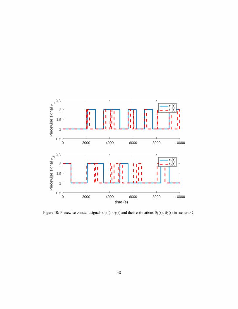
measurements of both outputs in the first 2000s and then replays the recordeddata periodically starting from t = 2000s. In this case, the signals zil(t) do notfollow anymore the corresponding varying frequency profiles ωσl(t) (see Fig. 9).This fact leads to a mismatch between σl(t) and σl(t), as shown in Fig. 10, whichprovides an information about both the output channels being attacked (see Fig.11). In fact, based on the information provided by σl(t), a replay attack acting onthe first output channel is detected at time t = 2031s, while a replay attack on thesecond output channel is detected at time t = 2044s (notice that due to σl(t) being
24

0 2000 4000 6000 8000 100006.1
6.15
6.2
6.25
Firs
t out
put c
hann
el
y(t)y
ref(t)
0 2000 4000 6000 8000 10000
time (s)
6.5
6.55
6.6
6.65
6.7
Sec
ond
outp
ut c
hann
el
Figure 5: Output signal y(t) and reference yre f (t) in scenario 1.
25

0 1000 2000 3000 4000 5000 6000 7000 8000 9000 10000-0.02
-0.01
0
0.01
0.02
Firs
t ban
d-pa
ss fi
lter
0.2
0.4
0.6
Fre
quen
cy ω
σ 1
(t)
(rad
/s)
z11
(t)
z21
(t)
ωσ 1
(t)
0 1000 2000 3000 4000 5000 6000 7000 8000 9000 10000
time (s)
-0.02
-0.01
0
0.01
0.02
Sec
ond
band
-pas
s fil
ter
0.2
0.4
0.6
Fre
quen
cy ω
σ 2
(t)
(rad
/s)
z12
(t)
z22
(t)
ωσ 2
(t)
Figure 6: Outputs of the band-pass filters zil(t) and varying frequency ωσ (t) in scenario 1.
26

0 2000 4000 6000 8000 100000.5
1
1.5
2
2.5
Pie
cew
ise
sign
al σ
1
σ1(t)σ1(t)
0 2000 4000 6000 8000 10000
time (s)
0.5
1
1.5
2
2.5
Pie
cew
ise
sign
al σ
2
σ2(t)σ2(t)
Figure 7: Piecewise constant signals σ1(t), σ2(t) and their estimations σ1(t), σ2(t) in scenario 1.
27

0 100 200 300 400 500-0.5
0
0.5
1
1.5
σ1(t) == σ1(t)
0 100 200 300 400 500
time (s)
-0.5
0
0.5
1
1.5
σ2(t) == σ2(t)
Figure 8: Result of the replay attack detection test in scenario 1.
28

calculated as in (39), σ1(t) , σ1(t) and σ2(t) , σ2(t) hold intermittently underreplay attack).
0 1000 2000 3000 4000 5000 6000 7000 8000 9000 10000-0.02
-0.01
0
0.01
0.02
Firs
t ban
d-pa
ss fi
lter
0.2
0.4
0.6
Fre
quen
cy ω
σ 1
(t)
(rad
/s)
z11
(t)
z21
(t)
ωσ 1
(t)
0 1000 2000 3000 4000 5000 6000 7000 8000 9000 10000
time (s)
-0.02
-0.01
0
0.01
0.02
Sec
ond
band
-pas
s fil
ter
0.2
0.4
0.6
Fre
quen
cy ω
σ 2
(t)
(rad
/s)
z12
(t)
z22
(t)
ωσ 2
(t)
Figure 9: Outputs of the band-pass filters zil(t) and varying frequency ωσ (t) in scenario 2.
5.3. Scenario 3In the last scenario, only the first output is considered to be affected by the
replay attack starting from t = 200s. In this case, the signals zi1(t), i = 1,2, donot follow the profile of ωσ1(t), while the signals zi2(t), i = 1,2, follow ωσ2(t)throughout the simulation (see Fig. 12). Consequently, a mismatch between σ1(t)and σ1(t) arises, as shown in Fig. 13, which allows detecting a replay attack actingon the first output channel at time t = 2032s (see Fig. 14).
5.4. Comparison between N = 2 and N = 4In order to conclude the analysis of the performance of the proposed approach,
a comparison between the detector designed for a number of frequencies N = 2
29
0 2000 4000 6000 8000 100000.5
1
1.5
2
2.5
Pie
cew
ise
sign
al σ
1
σ1(t)σ1(t)
0 2000 4000 6000 8000 10000
time (s)
0.5
1
1.5
2
2.5
Pie
cew
ise
sign
al σ
2
σ2(t)σ2(t)
Figure 10: Piecewise constant signals σ1(t), σ2(t) and their estimations σ1(t), σ2(t) in scenario 2.
30

0 2000 4000 6000 8000 10000-0.5
0
0.5
1
1.5
σ1(t) == σ1(t)
0 2000 4000 6000 8000 10000
time (s)
-0.5
0
0.5
1
1.5
σ2(t) == σ2(t)
Figure 11: Result of the replay attack detection test in scenario 2.
31

0 10 20 30 40 50 60 70 80 90 100-0.02
-0.01
0
0.01
0.02
Firs
t ban
d-pa
ss fi
lter
0.2
0.4
0.6
Fre
quen
cy ω
σ 1
(t)
(rad
/s)
z11
(t)
z21
(t)
ωσ 1
(t)
0 10 20 30 40 50 60 70 80 90 100
time (s)
-0.02
-0.01
0
0.01
0.02
Sec
ond
band
-pas
s fil
ter
0.2
0.4
0.6
Fre
quen
cy ω
σ 2
(t)
(rad
/s)
z12
(t)
z22
(t)
ωσ 2
(t)
Figure 12: Outputs of the band-pass filters zil(t) and varying frequency ωσ (t) in scenario 3.
32

0 2000 4000 6000 8000 100000.5
1
1.5
2
2.5
Pie
cew
ise
sign
al σ
1
σ1(t)σ1(t)
0 2000 4000 6000 8000 10000
time (s)
0.5
1
1.5
2
2.5
Pie
cew
ise
sign
al σ
2
σ2(t)σ2(t)
Figure 13: Piecewise constant signals σ1(t), σ2(t) and their estimations σ1(t), σ2(t) in scenario 3.
33

0 2000 4000 6000 8000 10000-0.5
0
0.5
1
1.5
σ1(t) == σ1(t)
0 2000 4000 6000 8000 10000
time (s)
-0.5
0
0.5
1
1.5
σ2(t) == σ2(t)
Figure 14: Result of the replay attack detection test in scenario 3.
34

and N = 4 is performed. Note that the case N = 2 corresponds to the same de-signed parameters used in the simulations of scenarios 1-3 described previously.On the other hand, the choice N = 4 leads to ω1 = 1.4rad/s, ttrans = 37.40s andTs = 149.60s (see Fig. 15 for an exemplification of the outputs of the band-passfilters for this detector when no replay attack is affecting the system throughouta simulation). For each case, 100 simulations have been performed, in each ofwhich a replay attack affected both of the output channels starting from a time t1randomly generated from a uniform distribution with support [100s,300s]. Overthe considered simulations, the detector with N = 2 has detected a replay attackacting on the first (second) output channel in an average time of 400s (458s),while the detector with N = 4 has performed the detection in an average time of2694s (2605s). This comparison suggests that choosing a binary set of frequen-cies leads to a better performance of the detector.
0 1000 2000 3000 4000 5000 6000 7000 8000 9000 10000-0.02
-0.01
0
0.01
0.02
Firs
t ban
d-pa
ss fi
lter
0
0.2
0.4
0.6
0.8
Fre
quen
cy ω
σ 1
(t)
(rad
/s)
z11
(t)
z21
(t)
z31
(t)
z41
(t)
ωσ 1
(t)
0 1000 2000 3000 4000 5000 6000 7000 8000 9000 10000
time (s)
-0.02
-0.01
0
0.01
0.02
Sec
ond
band
-pas
s fil
ter
0
0.2
0.4
0.6
0.8F
requ
ency
ωσ
2(t
) (r
ad/s
)
z12
(t)
z22
(t)
z32
(t)
z42
(t)
ωσ 2
(t)
Figure 15: Outputs of the band-pass filters zil(t) and varying frequency ωσ (t) with N = 4 (noreplay attacks).
35
6. Conclusions
In this work, replay attacks on cyber-physical systems were considered, andan innovative method for detecting this type of attacks affecting control systemshas been proposed. The developed approach is based on adding an authenticationsignal (signature), to the input. In particular, the chosen signature is frequency-based, which means that frequency-varying sinusoidal signals are used. Morespecifically, a piecewise constant signal σ(t) determines at each instant of timethe frequency of the authentication signal. By filtering the signature with a dy-namic decoupler, designed using the vector fitting method, it is ensured that agiven signature affects only one of the available output channels. This propertycan be exploited in order to determine which channels are being affected by thereplay attack. By filtering the output signals using a bank of band-pass filters, eachone designed to let pass only the component corresponding to a specific frequencyamong the ones used for the generation of the authentication signal, an estimationσ(t) of σ(t) can be determined. Then, by comparing the known piecewise con-stant signal σ(t) with its estimation, an information about whether a replay attackis being carried out or not is provided (replay attack detection algorithm). Thechoice of the design parameters involved in the proposed strategy has been dis-cussed thoroughly. Finally, the signal generator and the detector logic have beenevaluated by considering an example based on a quadruple-tank process. Threesimulation scenarios have demonstrated the effectiveness of the proposed tech-nique, and shown its main characteristics. In particular, the proposed method hasshown not to trigger false alarms while being able to identify successfully thechannels affected by the replay attack in all the considered scenarios. The com-parison between detector designed with different numbers of frequencies (N = 2and N = 4) has suggested that choosing a binary set of frequencies leads to a betterperformance of the detector.
Future work will aim at extending the proposed approach to discrete-time sys-tems, as well as to add more complexity to the problem formulation by taking intoaccount possible nonlinearity and structural uncertainties affecting the system’smatrices. Moreover, the information provided by the proposed detection methodwill be used to develop secure control strategies, with the aim of compensating thenegative effects of replay attacks, which can potentially disrupt a control systemwhen wrong measurements are fed back to the observer/controller instead of thetrue ones.
36

7. Acknowledgements
This work has been partially funded by the Spanish State Research Agency(AEI) and the European Regional Development Fund (ERFD) through the projectsDEOCS (ref. MINECO DPI2016-76493) and SCAV (ref. MINECO DPI2017-88403-R), by AGAUR of the Generalitat de Catalunya through the AdvancedControl Systems (SAC) group grant (2017 SGR 482) and by the AEI through theMaria de Maeztu Seal of Excellence to IRI (MDM-2016-0656) and the grant Juande la Cierva -Formacion (FJCI-2016-29019). The authors would like to thankMassimiliano Rotondo for his valuable comments and discussions about the ap-plication of frequency-varying signals.
References
[1] F. Pasqualetti, F. Dorfler, F. Bullo, Attack detection and identification incyber-physical systems, IEEE Transactions on Automatic Control 58 (2013)2715–2729.
[2] M. Bishop, Computer Security: Art and Science, Addison-Wesley Profes-sional, 2002.
[3] J. P. Conti, The day the samba stopped, Engineering & Technology 5 (2010)46–47.
[4] D. Moore, V. Paxson, S. Savage, C. Shannon, S. Staniford, N. Weaver, Insidethe Slammer worm, IEEE Security & Privacy 99 (2003) 33–39.
[5] J. P. Farwell, R. Rohozinski, Stuxnet and the future of cyber war, Survival53 (2011) 23–40.
[6] M. Blanke, M. Kinnaert, J. Lunze, M. Staroswiecki, J. Schroder, Diagnosisand fault-tolerant control, Springer Berlin, 2006.
[7] I. Hwang, S. Kim, Y. Kim, C. E. Seah, A survey of fault detection, isola-tion, and reconfiguration methods, IEEE Transactions on Control SystemsTechnology 18 (2010) 636–653.
[8] K. Ji, Y. Lu, L. Liao, Z. Song, D. Wei, Prognostics enabled resilient controlfor model-based building automation systems, in: Proceedings of the 12thConference of International Building Performance Simulation Association(2011), pp. 286–293.
37

[9] C. G. Rieger, K. Villez, Resilient control system execution agent (Re-CoSEA), in: Proceedings of the 5th IEEE International Symposium onResilient Control Systems (2012), pp. 143–148.
[10] W. C. Lin, K. Villez, H. E. Garcia, Experimental validation of a resilientmonitoring and control system, Journal of Process Control 24 (2014) 621–639.
[11] D. Rotondo, V. Puig, F. Nejjari, J. Romera, A fault-hiding approach forthe switching quasi-LPV fault tolerant control of a four-wheeled omnidirec-tional mobile robot, IEEE Transactions on Industrial Electronics 62 (2015)3932–3944.
[12] D. Rotondo, F. R. Lopez-Estrada, F. Nejjari, J. C. Ponsart, D. Theilliol,V. Puig, Actuator multiplicative fault estimation in discrete-time LPV sys-tems using switched observers, Journal of the Franklin Institute 353 (2016)3176–3191.
[13] K. Zhou, J. C. Doyle, K. Glover., Robust and optimal control, Prentice-Hall,Inc., Upper Saddle River, NJ, USA., 1996.
[14] M. Rodrigues, H. Hamdi, N. B. Braiek, D. Theilliol, Observer-based faulttolerant control design for a class of LPV descriptor systems, Journal of theFranklin Institute 351 (2014) 3104 – 3125.
[15] D. Rotondo, Advances in gain-scheduling and fault tolerant control tech-niques, Springer, 2017.
[16] F. Gomez-Bravo, J. M. Garcıa, R. J. Naharro, J. G. Galan, M. S. Raya, Ex-perimental platform for studying hardware vulnerabilities on mobile robots:I2c bus, a case of study, Revista Iberoamericana de Automatica e InformaticaIndustrial RIAI 14 (2017) 205–216.
[17] A. A. Cardenas, S. Amin, S. Sastry, Research challenges for the securityof control systems, in: Proceedings of the 3rd Conference on Hot topics insecurity (2008), p. 6.
[18] S. Amin, A. A. Cardenas, S. Sastry, Safe and secure networked controlsystems under denial-of-service attacks, in: Proceedings of the InternationalWorkshop on Hybrid Systems: Computation and Control (2009), Springer,pp. 31–45.
38

[19] G. Carl, G. Kesidis, R. R. Brooks, S. Rai, Denial-of-service attack-detectiontechniques, IEEE Internet computing 10 (2006) 82–89.
[20] Z. Tan, A. Jamdagni, X. He, P. Nanda, R. P. Liu, Denial-of-service attackdetection based on multivariate correlation analysis, in: Proceedings of theInternational Conference on Neural Information Processing (2011), pp. 756–765.
[21] L. Zhao, G.-H. Yang, Adaptive sliding mode fault tolerant control for non-linearly chaotic systems against DoS attack and network faults, Journal ofthe Franklin Institute 354 (2017) 6520–6535.
[22] Y. Xiang, K. Li, W. Zhou, Low-rate DDoS attacks detection and traceback byusing new information metrics, IEEE Transactions on Information Forensicsand Security 6 (2011) 426–437.
[23] A. Gupta, C. Langbort, T. Basar, Optimal control in the presence of anintelligent jammer with limited actions, in: Proceedings of the 49th IEEEConference on Decision and Control (2010), pp. 1096–1101.
[24] R. Zhang, P. Venkitasubramaniam, Stealthy control signal attacks in linearquadratic gaussian control systems: Detectability reward tradeoff, IEEETransactions on Information Forensics and Security 12 (2017) 1555–1570.
[25] B. Li, R. Lu, W. Wang, K.-K. R. Choo, DDOA: A dirichlet-based detectionscheme for opportunistic attacks in smart grid cyber-physical system, IEEETransactions on Information Forensics and Security 11 (2016) 2415–2425.
[26] Y. Mo, B. Sinopoli, Secure control against replay attacks, in: Proceedingsof the 47th IEEE Annual Allerton Conference on Communication, Control,and Computing (2009), pp. 911–918.
[27] M. A. Sid, S. Chitraganti, K. Chabir, Medium access scheduling for inputreconstruction under deception attacks, Journal of the Franklin Institute 354(2017) 3678–3689.
[28] J. Liu, J. Xia, E. Tian, S. Fei, Hybrid-driven-based h∞ filter design for neuralnetworks subject to deception attacks, Applied Mathematics and Computa-tion 320 (2018) 158–174.
39

[29] F. Miao, M. Pajic, G. J. Pappas, Stochastic game approach for replay attackdetection, in: Proceedings of the 52nd IEEE Conference on Decision andControl (2013), pp. 1854–1859.
[30] M. Zhu, S. Martınez, On the performance analysis of resilient networkedcontrol systems under replay attacks, IEEE Transactions on Automatic Con-trol 59 (2014) 804–808.
[31] M. Ma, P. Zhou, D. Du, C. Peng, M. Fei, H. M. AlBuflasa, Detecting replayattacks in power systems: A data-driven approach, in: Advanced Compu-tational Methods in Energy, Power, Electric Vehicles, and Their Integration,Springer, 2017, pp. 450–457.
[32] K. Kashima, D. Inoue, Replay attack detection in control systems with quan-tized signals, in: Proceedings of the IEEE European Control Conference(2015), pp. 782–787.
[33] B. Tang, L. D. Alvergue, G. Gu, Secure networked control systems againstreplay attacks without injecting authentication noise, in: Proceedings of theIEEE American Control Conference (2015), pp. 6028–6033.
[34] A. Teixeira, D. Perez, H. Sandberg, K. H. Johansson, Attack models andscenarios for networked control systems, in: Proceedings of the 1st ACMInternational Conference on High Confidence Networked Systems (2012),pp. 55–64.
[35] R. Mehra, J. Peschon, An innovations approach to fault detection and diag-nosis in dynamic systems, Automatica 7 (1971) 637–660.
[36] R. Costa-Castello, J. M. Olm, H. Vargas, G. A. Ramos, An educationalapproach to the internal model principle for periodic signals, InternationalJournal of Innovative Computing, Information and Control 8 (2012) 5591–5606.
[37] G. F. Franklin, J. D. Powell, M. L. Workman, Digital Control of DynamicSystems, Addison Wesley Longman, 3rd. edition, 1997.
[38] S. Skogestad, I. Postlethwaite, Multivariable Feedback Control: Analysisand Design, Wiley, 2005.
40

[39] O. N. Gasparyan, Linear and nonlinear multivariable feedback control: aclassical approach, John Wiley and Sons, Ltd., 2008.
[40] Q.-G. Wang, Decoupling Control, Lecture Notes in Control and InformationSciences, Vol. 285, Springer-Verlag Berlin Heidelberg, 2003.
[41] B. Gustavsen, A. Semlyen, Rational approximation of frequency domainresponses by vector fitting, IEEE Transactions on Power Delivery 14 (1999)1052–1061.
[42] B. Gustavsen, Improving the pole relocating properties of vector fitting,IEEE Transactions on Power Delivery 21 (2006) 1587–1592.
[43] A. Semlyen, B. Gustavsen, Vector fitting by pole relocation for the stateequation approximation of nonrational transfer matrices, Circuits, Systemsand Signal Processing 19 (2000) 549–566.
[44] B. Gustavsen, A. Semlyen, Simulation of transmission line transient usingvector fitting and modal decomposition, IEEE Transactions on Power Deliv-ery 13 (1998) 605–614.
[45] R. N. Bracewell, The Fourier transform and its applications, Boston:McGraw-Hill, 2000.
[46] L. J. Van Vliet, Windowed Fourier transform, Lectures about Signals andSystems (2002).
[47] F. Harris, On the use of windows for harmonic analysis with the discreteFourier transform, Proceedings of the IEEE 66 (1978) 51–83.
[48] N. Geckinli, D. Yavuz, Some novel windows and a concise tutorial com-parison of window families, IEEE Transactions on Acoustics, Speech, andSignal Processing 26 (1978) 501–507.
[49] P. Singla, T. Singh, Desired order continuous polynomial time window func-tions for harmonic analysis, IEEE Transactions on Instrumentation and Mea-surement 59 (2010) 2475–2481.
[50] H. Zumbahlen, Linear circuit design handbook, Elsevier Newnes Press,2008.
[51] K. Ogata, Modern control engineering, Prentice Hall, 1970.
41

[52] A. Le Bot, Foundation of statistical energy analysis, Oxford UniversityPress, 2015.
[53] A. Teixeira, I. Shames, H. Sandberg, K. H. Johansson, A secure controlframework for resource-limited adversaries, Automatica 51 (2015) 135–148.
[54] K. H. Johansson, The quadruple-tank process: A multivariable laboratoryprocess with an adjustable zero, IEEE Transactions on control systems tech-nology 8 (2000) 456–465.
[55] D. Deschrijver, M. Mrozowski, T. Dhaene, D. De Zutter, Macromodeling ofmultiport systems using a fast implementation of the vector fitting method,IEEE Microwave and Wireless Components Letters 18 (2008) 383–385.
42
Related Documents