Brigham Young University BYU ScholarsArchive All Faculty Publications 2015-4 Detect and Avoid for Small Unmanned Aircraſt Systems using ADS-B Timothy McLain Mechanical Engineering Department, Brigham Young University, [email protected] Laith R. Sahawneh Mechanical Engineering Department, Brigham Young University See next page for additional authors Follow this and additional works at: hps://scholarsarchive.byu.edu/facpub Part of the Mechanical Engineering Commons Original Publication Citation Sahawneh, L., Duffield, M., Beard, R., and McLain, T. Detect and Avoid for Small Unmanned Aircraſt Systems using ADS-B, Air Traffic Control Quarterly, vol. 23, no. 2-3, pp. 203-240, April 2015. is Peer-Reviewed Article is brought to you for free and open access by BYU ScholarsArchive. It has been accepted for inclusion in All Faculty Publications by an authorized administrator of BYU ScholarsArchive. For more information, please contact [email protected], [email protected]. BYU ScholarsArchive Citation McLain, Timothy; Sahawneh, Laith R.; Duffield, Mahew O.; and Beard, Randall W., "Detect and Avoid for Small Unmanned Aircraſt Systems using ADS-B" (2015). All Faculty Publications. 1895. hps://scholarsarchive.byu.edu/facpub/1895

Welcome message from author
This document is posted to help you gain knowledge. Please leave a comment to let me know what you think about it! Share it to your friends and learn new things together.
Transcript
Brigham Young UniversityBYU ScholarsArchive
All Faculty Publications
2015-4
Detect and Avoid for Small Unmanned AircraftSystems using ADS-BTimothy McLainMechanical Engineering Department, Brigham Young University, [email protected]
Laith R. SahawnehMechanical Engineering Department, Brigham Young University
See next page for additional authors
Follow this and additional works at: https://scholarsarchive.byu.edu/facpubPart of the Mechanical Engineering Commons
Original Publication CitationSahawneh, L., Duffield, M., Beard, R., and McLain, T. Detect and Avoid for Small UnmannedAircraft Systems using ADS-B, Air Traffic Control Quarterly, vol. 23, no. 2-3, pp. 203-240, April2015.
This Peer-Reviewed Article is brought to you for free and open access by BYU ScholarsArchive. It has been accepted for inclusion in All FacultyPublications by an authorized administrator of BYU ScholarsArchive. For more information, please contact [email protected],[email protected].
BYU ScholarsArchive CitationMcLain, Timothy; Sahawneh, Laith R.; Duffield, Matthew O.; and Beard, Randall W., "Detect and Avoid for Small Unmanned AircraftSystems using ADS-B" (2015). All Faculty Publications. 1895.https://scholarsarchive.byu.edu/facpub/1895

AuthorsTimothy McLain, Laith R. Sahawneh, Matthew O. Duffield, and Randall W. Beard
This peer-reviewed article is available at BYU ScholarsArchive: https://scholarsarchive.byu.edu/facpub/1895
Detect and Avoid for Small Unmanned Aircraft Systems
using ADS-B
Laith R. Sahawneh, Matthew O. Du�eld, Randal W. Beard, Timothy W. McLainBrigham Young University
With the increasing demand to integrate unmanned aircraft systems (UAS) into the NationalAirspace System (NAS), new procedures and technologies are necessary to ensure safe airspaceoperations and minimize the impact of UAS on current airspace users. Currently, small UAS facelimitations on their utilization in civil airspace because they do not have the ability to detect andavoid other aircraft. In this article, we will present a framework that consists of an AutomaticDependent Surveillance-Broadcast (ADS-B)-based sensor, track estimator, conflict/collision de-tection, and resolution that mitigates collision risk. ADS-B o↵ers long range, omni-directionalintruder detection with comparatively few size, weight, power, and cost demands. The proposedconflict/collision detection and planning algorithms for conflict/collision resolution are designed inthe local level frame, which is unrolled, unpitched body frame where the ownship is stationary atthe center of the map. The path planning method is designed to be multi-resolutional at increasingdistance from the ownship to account for both self-separation and collision avoidance thresholds.We demonstrate and validate this approach using simulated ADS-B measurements.
INTRODUCTION
The number of applications of unmanned aircraft systems (UAS) is growing at a significant pace.Consequently the need for UAS in the National Airspace System is compounding at a similar rate.Governmental institutions are increasingly adopting UAS to perform tasks such as weather re-search, search and rescue, wildlife surveillance, law enforcement, wildfire monitoring, and militarytraining. A report compiled by the US Department of Transportation on UAS service demandsestimates that by the year 2035 there will be approximately 70,000 UAS operated by federal,state, and local departments and agencies (Unmanned Aircraft System (UAS) Service Demand2015-2035 , 2013). In the private sector, the ever growing number of UAS applications includesa wide variety of industries and tasks ranging from smoke stack inspection to cinematography tocrop dusting to oil exploration to news and tra�c reporting. The demand for UAS operations ismanifest by the approximately six hundred petitions as of March 2015 to allow UAS operationsunder Section 333 of the FAA Modernization and Reform Act of 2012 (FAA Modernization andReform Act of 2012 , 2014).
1

While UAS operations have increased as a result of the Section 333 exemptions approved sinceSeptember of 2014, the overall realized benefit of UAS operations is still a small fraction of thedemand. Additionally Section 333 exemptions are not a long-term solution to supporting UASin the National Airspace System. In laying the foundation for a long-term solution for UAS inthe NAS, the Federal Aviation Administration (FAA) has mandated that UAS be capable of anequivalent level of safety (ELOS) to the see-and-avoid mandate for manned aircraft (Hottman,Hansen, & Berry, 2009; Federal Aviation Administration, 2015). As a result, similar to a pilot’sability to visually scan the surrounding airspace for possible intruding aircraft and take action toavoid a collision, a UAS must be capable of monitoring and avoiding other manned or unmannedaircraft with which it may collide. This detect-and-avoid (DAA) manadate is the capability of aUAS to remain well clear and avoid collisions with other air tra�c (George, 2009). It is desirablethat the DAA system should include both self-separation and collision avoidance functions. Theself-separation function is responsible to maintain the well clear distance by maneuvering the UASwithin a su�cient time to prevent activation of a collision avoidance maneuver. On the other hand,the collision avoidance function should act within a relatively short time frame to maneuver theUAS to prevent an intruder from penetrating the collision volume. The collision avoidance functionis engaged when all other modes of separation fail to prevent an imminent collision. It is the lastresort e↵ort to steer the UAS onto a safe course. Ultimately DAA capability will provide UAS anequivalent level of safety to the current manned aircraft procedures.
In general, the DAA functionality can be broken into three sub-functions: detect and track,conflict/collision detection, and avoidance. The main role of the first sub-function is to detect anyintruders and track the motion of the detected object. Not every aircraft that is observed by thesensing system, however, presents a conflict or collision threat. Therefore the conflict/collision de-tection system determines whether or not an approaching intruder aircraft is on a conflict/collisioncourse. The term conflict is associated with self-separation and it usually implies an event wheretwo aircraft come within 5 to 10 nautical miles over time horizons on the order of minutes (Paielli& Erzberger, 1997; Hu, Lygeros, Prandini, & Sastry, 1999). On the other hand, the term collisiondetection and avoidance is used for close proximity encounters over time horizons on the order oftens of seconds (Angelov, 2012).
For small UAS weighing less than 55 pounds, the algorithms and hardware necessary for DAAmake up a notable portion of the available size, weight, and power (SWaP) resources. Scalingtraditional sensors down to small UAS sizes often requires compromises in range, accuracy, field ofview, or processing speed. Such compromises reduce the overall capability of the DAA system and,consequently, decrease the assurance of self-separation/collision avoidance. Radar is one sensorthat is widely used for air-to-air detection in manned aircraft. One of the primary strengths ofradar is the ability to detect all objects regardless of cooperative sensor equipage or functionality.In applying radar to small UAS, SWaP constraints impose restrictions on the hardware thatresult in significant trade o↵s between radar range, bearing accuracy, and field of view. At a settransmit power, improving the range requires a narrower beam, which also improves the bearingaccuracy. Narrowing the beam, however, reduces the field of view and consequently requiresadditional antennas or a method to steer the beam. Demonstrated hardware that falls within theSWaP limitations of small UAS is not currently suited to support a feasible set of range, bearing
2

accuracy, and field of view requirements (Mackie, Spencer, & Warnick, 2014). Optical sensorssuch as cameras are also candidate sensors for DAA on small UAS. Similar to radar, vision-basedintruder detection methods do not require cooperative communication from intruders. Flighttesting of visual methods has achieved intruder detection at 0.54 nmi from a small UAS (J. Lai,Ford, Mejias, Shea, & Walker, 2012). Ground-based testing has resulted in detection up 4.3nmi (Dey, Geyer, Singh, & Digioia, 2009). The flight tested range of 0.54 nmi is promising, butnot su�cient to provide enough avoidance time for high-speed intruders. Even with su�cientrange, visual methods inherently have low range accuracy. Adverse weather conditions such asfog, clouds, precipitation, and sun glare can reduce overall visibility and significantly limit visualintruder detection. While recent developments have improved visual intruder detection, suchmethods are not yet suitable for DAA implementation on small UAS.
Automatic Dependent Surveillance-Broadcast (ADS-B) is a cooperative sensor that is a promis-ing option for DAA on small UAS. It has been demonstrated in small UAS flight testing to havean omni-directional range of 20 nmi (Moody & Strain, 2009), and due to the fact that the co-operative information is shared over radio waves it is relatively una↵ected by adverse weatherconditions. An omni-directional antenna and low-power requirements for both transponder andreceiver hardware contribute to the promising characteristics of ADS-B. Two drawbacks of ADS-Bare its dependence on global positioning system (GPS) information and its fundamentally coop-erative nature. While GPS coverage of the national airspace is very good, there are areas whereGPS information can become degraded such as narrow valleys or urban canyons. Furthermore,the cooperative aspect of ADS-B requires widespread adoption of ADS-B technology to ensuredetect-and-avoid reliability. While the Federal Aviation Administration does not yet require allaircraft to be equipped with ADS-B transponders, the 2020 mandate requiring all aircraft in A,B, C, and some E class airspace to equip with ADS-B (Federal Aviation Administration, 2010b)is a significant step.
There is also a considerable body of work on conflict/collision detection and risk assessmentmethods. A survey of 68 conflict detection and resolution methods is presented in (Kuchar &Yang, 2000), and a recent survey is conducted by (Albaker & Rahim, 2010; Angelov, 2012).These di↵erent methods can be classified under four fundamental approaches: deterministic orstraight line, worst case, probabilistic, and flight plan sharing. Many of these methods stress thedeterministic approach, where a single trajectory of an intruder is predicted using straight-lineextrapolation. This is a reasonable approach when there is a perfect knowledge of the states ofthe detected intruder. In practice, however, the uncertainty free model could lead to erroneousprediction of the collision threat. While, many of these techniques are applicable for either conflictor collision detection, an appropriate scaling in design parameters, assumptions, and thresholds isrequired.
Similarly, airborne conflict/collision avoidance has gained considerable attention, and variousmethods and approaches have been suggested in the literature. Among the many collision avoid-ance algorithms, the local or reactive motion planning approaches are considered to be the mostsuitable approach for UAS collision avoidance. This is because a collision event occurs over arelatively short time horizon, which requires a planning method that promptly reacts to plan anavoidance maneuver using limited computation power. Moreover, reactive planning methods do
3

not require a priori knowledge of the environment. Reactive path planning is also well suited fordynamic environments where sensor information is uncertain and incomplete. The most commonreactive path planning approaches are geometric-based guidance methods (Hyunjin, 2013; Ra-jnikant, Saunders, & Beard W., 2012) and potential field methods (Lam, Mulder, Van Paassen,Mulder, & Van Der Helm, 2009; Sahawneh, Randal W. Beard, & Bai, 2013). The sampling-basedmethods, like Probability Road Maps (PRM) (Kavraki, Svestka, Latombe, & Overmars, 1996)and Rapidly-exploring Random Trees (RRTs) (LaValle, 1998) have shown considerable success forobstacle avoidance and path planning, especially for ground robots. They often require significantcomputation time for replanning paths making them unsuitable for reactive avoidance. Recentextensions to the basic RRT algorithm, however show promising results for uncertain environ-ments and nontrivial dynamics (Luders, Karaman, & How, 2013; Kothari & Postlethwaite, 2013;Luders, Karaman, Frazzoli, & How, 2010). Cell decomposition is another widely used path plan-ning approach that partitions the free area of the configuration space into cells, which then areconnected to generate a graph (Mirolo & Pagello, 1995). Generally, cell decomposition techniquesare considered to be global path planners that require some a priori knowledge of the environment.A feasible path is found from the start to goal configuration by searching the connectivity graphusing search algorithms, like A
⇤ or Dijkstra’s algorithm (Dijkstra, 1959).This article presents a complete detect-and-avoid solution for small unmanned aircraft includ-
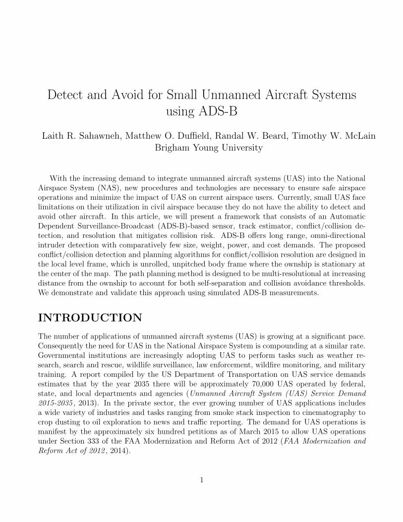
ing reliable intruder sensing, multi-target tracking and estimation, conflict/collision detection, andself-separation/collision avoidance. As shown in Figure 1, the ADS-B Out transmissions are re-ceived by a dual-link ADS-B In receiver. This receiver decodes the raw signal and passes it tothe intruder tracker/estimator. In the estimator the intruder state measurements are processed tohave a coherent set of units and then passed through a Kalman filter. After Kalman filtering, theintruder position and velocity estimates are projected forward in time to identify possible conflictsor collisions. If either a conflict or collision threat is detected, the intruder position and velocityestimates and an activation flag are passed into the self-separation/collision avoidance algorithm.Once either the conflict or collision level of the avoidance logic has been activated a new, conflictand collision-free path is generated. In the case of long-range intruders that pose a conflict risk theownship takes less aggressive behavior due to the longer allowable reaction time. For short-rangecollision risks the ownship plans a much more aggressive action to quickly reduce the possibilityof a collision. The ultimate output of the DAA system is a revised set of ownship waypoints thatis free from conflict and collision risks. The system shown in Figure 1 and presented in this articleis a complete DAA system for small UAS. It is viable for both fixed wing and multirotor aircraft,and could reasonably be extended for larger UAS outside of the small UAS definition.
The purpose of this article is to explore ADS-B as a sensor for detect-and-avoid on smallunmanned aircraft and to demonstrate conflict/collision detection and self-separation/collisionavoidance methods that take advantage of ADS-B characteristics. For the methods and simu-lations presented, we assume that the intruder aircraft are equipped with ADS-B Out, in otherwords the ability to transmit their cooperative information. The small UAS ownship is assumedto have ADS-B Out and dual-link ADS-B In. Thus it is capable of both transmitting its cooper-ative information and receiving the cooperative information from all other aircraft. Consequentlythe responsibility of conflict detection, self-separation assurance, collision detection, and collision
4
Intruder Estimates and Conflict Flag
Intruder Tracking and Estimation
Conflict/ Collision Detection
Self-Separation Assurance/ Collision
Avoidance
Aircraft in the National Airspace System
Dual Link ADS-B In Receiver
Ownship Detect and Avoid System Structure
Ownship Path Manager
ADS-B In Data
Intruder Position and Velocity Estimates
Revised Ownship Waypoints
Note: All aircraft are ADS-B Out capable
ADS-B Out Signals
Figure 1: Proposed detect-and-avoid system structure diagram.
avoidance lies entirely on the small UAS ownship. Although these assumptions do not exactlymatch the requirements of the FAA 2020 mandate, they do represent a condition where full inte-gration of UAS into the NAS would be possible. Thus in addition to presenting a DAA system forsmall UAS, we submit that complete ADS-B equipage requirements would meet the wide demandfor significantly increased UAS operations in the NAS.
ADS-B ON SMALL UAS
ADS-B is rapidly becoming a major tool in the air tra�c management system. In 2010 theFAA issued a final rule for the implementation of ADS-B on manned aircraft (Federal AviationAdministration, 2010b). This ruling mandated ADS-B Out in key parts of the NAS. The FAAModernization and Reform Act of 2012 further directed the FAA to make plans for the adoption
5

of ADS-B In technology (FAA Modernization and Reform Act of 2012 , 2014). As a result of thelevel of adoption and capability of ADS-B technology, ADS-B is an attractive sensor for detectand avoid e↵orts on UAS.
This section provides a description of ADS-B and the associated regulations as they relateto detect and avoid. A statistical characterization of ADS-B error and drop out is derived fromthe current FAA regulations. Further, we explore the capability of ADS-B as a DAA sensor byexamining key characteristics and limitations of ADS-B.
Characteristics and Regulations of ADS-B
ADS-B is a cooperative sensor that supports the exchange of a wide variety of information overlong ranges. Information that is typically exchanged includes aircraft state information, stateerror estimates, aircraft identifiers, and aircraft operating indicators. This exchange occurs ap-proximately once per second (Cirillo, 2005). To exchange this information, two sets of hardwareare necessary, ADS-B In and ADS-B Out. As the names suggest, ADS-B In allows for informa-tion to be received, and ADS-B Out supports the broadcasting of information. The hardwareperforming these two functions can be sold separately or as a single unit. In addition to the In orOut capability of ADS-B hardware, ADS-B transmissions can occur over two di↵erent frequencies,1090 MHz and 978 MHz (Federal Aviation Administration, 2010b). The 1090 MHz ExtendedSquitter (ES) frequency is an internationally recognized ADS-B frequency. It is intended that thisfrequency be used for most commercial and high-performance aircraft. The 1090 MHz frequencyis the same frequency used for current Mode S transmissions. The Extended Squitter designationindicates a message packet that is much longer than the standard Mode S packet. This allowsfor the transmission of much more information than what is exchanged via secondary surveillanceradar (SSR). The 978 MHz Universal Access Transceiver (UAT) frequency is unique to UnitedStates airspace. It is primarily intended for private and low-altitude aircraft. ADS-B Out hard-ware is specific to one of these two frequencies. The airspace class in which an aircraft will operatedictates the required frequency. ADS-B In hardware also is specific to a particular frequency,but dual-link hardware that is capable of receiving transmissions on both frequencies is becomingincreasingly available.
FAA regulations set forth in the 2010 Final Rule dictate most aspects of ADS-B operation. Themessage elements, airspace class, transmit power, latency, and error characteristics are all amongthe aspects of ADS-B that are regulated by the FAA. While these regulations do add complexityto the implementation and operation of an ADS-B system, they also provide a consistent basisupon which ADS-B can be evaluated for DAA on small UAS.
Message Element Requirements
The message elements exchanged by ADS-B transmissions provide a view of the transmittingaircraft’s status. Table 1 shows a list of these elements that is arranged by functional category. Thestate elements transmitted are the latitude and longitude, barometric altitude, geometric altitude,and velocity. A certified position source must be used for latitude and longitude information.Typically a Satellite Based Augmentation System (SBAS) source is used. The barometric altitude
6
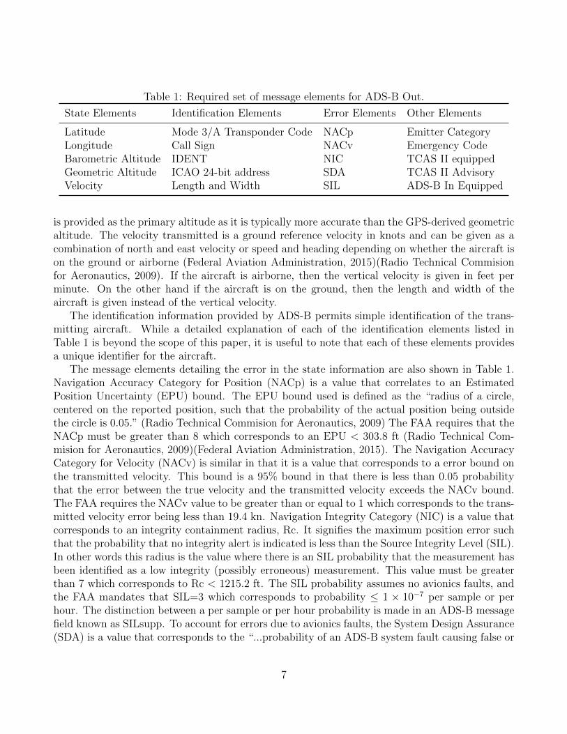
Table 1: Required set of message elements for ADS-B Out.
State Elements Identification Elements Error Elements Other Elements
Latitude Mode 3/A Transponder Code NACp Emitter CategoryLongitude Call Sign NACv Emergency CodeBarometric Altitude IDENT NIC TCAS II equippedGeometric Altitude ICAO 24-bit address SDA TCAS II AdvisoryVelocity Length and Width SIL ADS-B In Equipped
is provided as the primary altitude as it is typically more accurate than the GPS-derived geometricaltitude. The velocity transmitted is a ground reference velocity in knots and can be given as acombination of north and east velocity or speed and heading depending on whether the aircraft ison the ground or airborne (Federal Aviation Administration, 2015)(Radio Technical Commisionfor Aeronautics, 2009). If the aircraft is airborne, then the vertical velocity is given in feet perminute. On the other hand if the aircraft is on the ground, then the length and width of theaircraft is given instead of the vertical velocity.
The identification information provided by ADS-B permits simple identification of the trans-mitting aircraft. While a detailed explanation of each of the identification elements listed inTable 1 is beyond the scope of this paper, it is useful to note that each of these elements providesa unique identifier for the aircraft.
The message elements detailing the error in the state information are also shown in Table 1.Navigation Accuracy Category for Position (NACp) is a value that correlates to an EstimatedPosition Uncertainty (EPU) bound. The EPU bound used is defined as the “radius of a circle,centered on the reported position, such that the probability of the actual position being outsidethe circle is 0.05.” (Radio Technical Commision for Aeronautics, 2009) The FAA requires that theNACp must be greater than 8 which corresponds to an EPU < 303.8 ft (Radio Technical Com-mision for Aeronautics, 2009)(Federal Aviation Administration, 2015). The Navigation AccuracyCategory for Velocity (NACv) is similar in that it is a value that corresponds to a error bound onthe transmitted velocity. This bound is a 95% bound in that there is less than 0.05 probabilitythat the error between the true velocity and the transmitted velocity exceeds the NACv bound.The FAA requires the NACv value to be greater than or equal to 1 which corresponds to the trans-mitted velocity error being less than 19.4 kn. Navigation Integrity Category (NIC) is a value thatcorresponds to an integrity containment radius, Rc. It signifies the maximum position error suchthat the probability that no integrity alert is indicated is less than the Source Integrity Level (SIL).In other words this radius is the value where there is an SIL probability that the measurement hasbeen identified as a low integrity (possibly erroneous) measurement. This value must be greaterthan 7 which corresponds to Rc < 1215.2 ft. The SIL probability assumes no avionics faults, andthe FAA mandates that SIL=3 which corresponds to probability 1 ⇥ 10�7 per sample or perhour. The distinction between a per sample or per hour probability is made in an ADS-B messagefield known as SILsupp. To account for errors due to avionics faults, the System Design Assurance(SDA) is a value that corresponds to the “...probability of an ADS-B system fault causing false or
7

misleading information to be transmitted.” (Radio Technical Commision for Aeronautics, 2009)“The ADS-B system includes the ADS-B transmission equipment, ADS-B processing equipment,position source, and any other equipment that processes the position data transmitted by theADS-B system.” (Radio Technical Commision for Aeronautics, 2009) This information includeslatitude, longitude, velocity, accuracy metrics, or integrity metrics. The FAA mandates that theSDA value be 2 which corresponds to a probability 1 ⇥ 10�5 per flight hour (Radio TechnicalCommision for Aeronautics, 2009)(Federal Aviation Administration, 2015). While both the SDAand the SIL report a probability of exceeding the NIC, it is important to note that the SIL as-sumes no avionics fault, but the SDA is the probability that an avionics fault is the cause of thereported error. Elements in the fourth column, labeled as Other Elements, provide informationconcerning the operational status of the aircraft. The first field specifies the emitter categoryof the transmitting aircraft. The emitter category indicates the type of aircraft and gives someindication of aircraft weight, size, and maneuverability. The emergency code is the second item inthe fourth column. This code indicates if there is an emergency on-board the transmitting aircraftsuch as a medical emergency, minimum fuel, unlawful interference, or a downed aircraft. Suchinformation is useful both to identify aircraft that need special attention from air tra�c controlservices and for search and rescue e↵orts in a downed aircraft situation. The last three fields listedin column four of Table 1 indicate the equipage and activity of cooperative sensors. The thirdfield indicates whether Tra�c Collision Avoidance System (TCAS) is operable on the transmittingaircraft. Field four extends this and reports whether a tra�c advisory or resolution advisory is ine↵ect. The fifth field indicates whether the transmitting aircraft has ADS-B In capability.
Airspace and Power Requirements
The 2010 Final Rule on ADS-B mandated that by the year 2020 all aircraft in A, B, C, andsome E class airspace be equipped with ADS-B Out. There is no mandate for ADS-B In. TheFAA further mandated airspace where each of the two frequencies of ADS-B Out, 1090 MHz and978 MHz, can be used. Class A airspace requires 1090 MHz. Where ADS-B is required below18,000 ft, either 1090 MHz or 978 MHz is acceptable. Both B and C class airspace require ADS-B.ADS-B is also required within 30 nmi of a Class B airport reaching from the surface up to 10,000 ftmean sea level (MSL). Above B and C class airspace extending up to 10,000 ft MSL, ADS-B isrequired. E class airspace requires ADS-B from 10,000 ft MSL and above with the exception of thesurface to 2,500 ft above ground level (AGL). In other words, if 0 ft AGL is above 10,000 ft MSLthen there is a 2,500 ft region above ground level where ADS-B is not required. Finally ADS-Bis required above 3,000 ft MSL over the Gulf of Mexico within 12 nmi of the coast of the UnitedStates (Federal Aviation Administration, 2015). Figure 2 summarizes the airspace requirementsfor ADS-B Out (Federal Aviation Administration, 2012).
The range of ADS-B transmissions is largely dependent on the transmit power of the ADS-B transponder. FAA regulations mandate di↵erent levels of transmit power for 1090 MHz and978 MHz. For the 978 MHz frequency, there are three transmit power levels. Each level correspondsto a minimum transmit power and consequently a transmission range. The 1090 MHz frequencyalso has three levels which correspond to a minimum transmit power and range.
8

Figure 2: Diagram of airspace where ADS-B Out is required(Federal Aviation Administration, 2012).
While transmit ranges vary asa result of frequency congestion,antenna di↵erences, and otherexternal factors, estimated, air-to-air ranges for the 978 MHzfrequency extend from 10 nmi to90 nmi and for the 1090 MHzestimated ranges extend from10 nmi to 140 nmi (RadioTechnical Commision for Aero-nautics, 2009)(Radio Techni-cal Commision for Aeronautics,2011). Air-to-ground or ground-to-air transmissions have a muchlonger anticipated range as a re-sult of more sensitive receiversand more powerful transpondersthat are available for ground-based equipment.
Error Characterization
In addition to the error metrics outlined in Table 1, ADS-B is subject to several additional sourcesof error namely latency error, resolution error, and message success rate (MSR) error. Theseadditional sources of error, along with those previously defined in Table 1, play a role in definingan error characterization of ADS-B.
Due to processing needs, data latency is inherent in the ADS-B system. This latency falls intotwo categories. Total latency is the time from measurement to transmission and must be less than2.0 s. Of those 2.0 s, all but 0.6 s must be compensated for by the ownship. In compensatingfor latency the transmitting aircraft must “[extrapolate] the geometric position to the time ofmessage transmission.” (Federal Aviation Administration, 2015) The uncompensated 0.6 s of thetotal latency is referred to as uncompensated latency (UL) (Federal Aviation Administration,2015). It is the uncompensated latency that is the primary source of latency error.
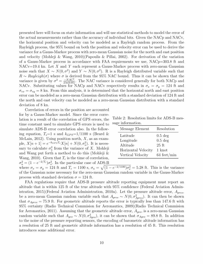
Resolution error results from encoding state information into an ADS-B message where theinformation is represented by discrete bits. Table 2 shows the resolution limits for an ADS-Bmessage (Radio Technical Commision for Aeronautics, 2009).
ADS-B regulations require that receivers are capable of supporting a given message successrate. For messages on the 978 MHz frequency this is 10%, and for messages on 1090 MHz, thisis approximately 15%. These success rates imply that one out of every 10 or 3 out of every 20messages is not received, thus resulting in message success rate error.
The NACp, NACv, NIC, SIL, SDA, latency error, resolution error, and MSR error provide abasis from which to derive an error characterization to model ADS-B. The error characterization
9
presented here will focus on state information and will use statistical methods to model the error ofthe actual measurements rather than the accuracy of individual bits. Given the NACp and NACv,the horizontal position and velocity can be modeled as a Rayleigh random process. From theRayleigh process, the 95% bound on both the position and velocity error can be used to derive thevariance for a Gauss-Markov process with zero-mean Gaussian noise for the north and east positionand velocity (Mohleji & Wang, 2010)(Papoulis & Pillai, 2002). For derivation of the variationof a Gauss-Markov process in accordance with FAA requirements we use, NACp=303.8 ft andNACv=19.4 kn. Let X and Y each represent a Gauss-Markov process with zero-mean Gaussiannoise such that X ⇠ N(0, �2) and Y ⇠ N(0, �2). R is a Rayleigh distributed variable such thatR ⇠ Rayleigh(�) where � is derived from the 95% NAC bound. Thus it can be shown that thevariance is given by �
2 = �NAC
2
2 ln(0.05) . The NAC variance is considered generally for both NACp andNACv. Substituting values for NACp and NACv respectively results in �
x
= �
y
= 124 ft and�
vx
= �
vy
= 8 kn. From this analysis, it is determined that the horizontal north and east positionerror can be modeled as a zero-mean Gaussian distribution with a standard deviation of 124 ft andthe north and east velocity can be modeled as a zero-mean Gaussian distribution with a standarddeviation of 8 kn.
Table 2: Resolution limits for ADS-B mes-sage information.
Message Element Resolution
Latitude 0.5 degLongitude 0.5 degAltitude 25 ftHorizontal Velocity 1 knotVertical Velocity 64 feet/min
Correlation of errors in the position are accountedfor by a Gauss-Markov model. Since the error corre-lation is a result of the correlation of GPS errors, thetime constant used to simulate GPS errors is used tosimulate ADS-B error correlation also. In the follow-ing equation, T
s
=1 s and k
GPS
=1/1100 s (Beard &McLain, 2012). Using position north, X, as an exam-ple, X[n+ 1] = e
�k
GPS
T
s
X[n] +N(0, �2u
). It is neces-sary to calculate �
2u
from the variance of X. Mohlejiand Wang put forth a method to do this (Mohleji &Wang, 2010). Given that T
c
is the time of correlation,�
2u
= (1� e
�2/Tc)�2
x
. In the particular case of ADS-Bwhere �
x
= �
y
= 124 ft and T
c
= 1100 s, �u
=p(1� e
�2/1100)�2x
= 5.28 ft. This is the varianceof the Gaussian noise necessary for the zero-mean Gaussian random variable in the Gauss-Markovprocess with standard deviation � = 124 ft.
FAA regulations require that ADS-B pressure altitude reporting equipment must report analtitude that is within 125 ft of the true altitude with 95% confidence (Federal Aviation Admin-istration, 2015)(Federal Aviation Administration, 2010a). Let the pressure altitude error, A
pres
,be a zero-mean Gaussian random variable such that A
pres
⇠ N(0, �2Apres
). It can then be shownthat �
Apres
= 75.9 ft. For geometric altitude reports the error is typically less than 147.6 ft with95% certainty (Radio Technical Commision for Aeronautics, 2009)(Radio Technical Commisionfor Aeronautics, 2011). Assuming that the geometric altitude error, A
geo
, is a zero-mean Gaussianrandom variable such that A
geo
⇠ N(0, �2Ageo
), it can be shown that �Ageo
= 89.8 ft. In additionto the noise of the pressure reporting sensors, the encoding of barometric altitude information hasa resolution of 25 ft and geometric altitude information has a resolution of 45 ft. This resolutionintroduces some additional error.
10

The error in the ADS-B reported vertical velocity varies with increasing vertical rate. Forvertical rates between ±500 ft/min the vertical rate tolerance is ±46 ft/min. For rates outsidethat range, the tolerance is 5% of the vertical rate (SAE International, 1996)(Radio TechnicalCommision for Aeronautics, 2003). Given the assumption that these tolerances are 95% bounds,it can be shown that the standard deviation of the climb rate is 27.96 ft/min for vertical ratesof ±500 ft/min. Additionally the vertical rate error is e↵ected by the resolution of the ADS-Bmessage encoding which is 64 ft/min.
The loss of valid ADS-B signal can be modeled using SIL, SDA, and MSR error. FAA regula-tions stipulate that position measurements outside the reported NIC can only be transmitted onceper 107 transmissions. The SDA requirements permit values outside the NIC with a probabilityof 10�5. MSR error requirements allow for a 10% or 15% message loss rate. These probabilitiesof erroneous or lost messages provide a method with which to model ADS-B signal dropout.
The error characteristics detailed above make it possible to model the error in ADS-B reportedhorizontal position, altitude, horizontal velocity, and vertical velocity. This results in a methodcapable of simulating ADS-B messages. It also provides a basis for estimating ADS-B messagesand developing conflict detection, collision detection, separation assurance and collision avoidancemethods.
ADS-B as a DAA Sensor
The characteristics and requirements of ADS-B make it a capable sensor for DAA on small UASin the National Airspace System. One key aspect of ADS-B that makes it feasible for use on smallUAS is the availability of ADS-B receivers the meet the (SWaP) constraints of a small UAS. TheClarity ADS-B receiver provides a dual-link ADS-B receiver that is 2.5 in by 2.5 in by 1.5 in, weighs0.344 lbs, and consumes 2.4 Watts of power. Freeflight Systems has also recently introduced theRANGR RXD which is a dual-link ADS-B receiver. While slightly larger at 5 in by 5.75 in by1.7 in, it still weighs less than one pound and consumes approximately 2.4 Watts of power. Thesehardware options both provide a suitable ADS-B In solution for small UAS.
Another key advantage of ADS-B is the long range at which information is available. Whilethere is a significant amount of variation in the range of ADS-B signals, the shortest expected rangeis 10 nmi. Flight tests of ADS-B units suitable for small UAS have demonstrated reliable rangesof up to 80 nmi (Moody & Strain, 2009). Additionally the long range of ADS-B is advantageousin that the quality of information transmitted over ADS-B does not degrade with range. Thus theaccuracy of ADS-B is not dependent on the size, power, or range of the transmitter and receiverunits. This is a significant advantage over radar and optical sensors, and makes conflict detectionand separation assurance path planning possible at long ranges.
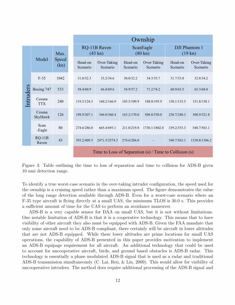
A compelling result of the long range availability of ADS-B messages is the time to loss ofseparation (TLOS) and time to collision (TC). Figure 3 shows the TLOS and TC for head-onand over-taking scenarios given di↵erent intruder aircraft and various small UAS ownships. Thedetection range is set to the FAA required minimum of 10 nmi, and the separation distance is0.66 nmi (Cook, Brooks, Cole, Hackenberg, & Raska, 2015). For this table a collision is defined asa violation of a 500 ft collision radius. The speeds listed are the maximum speeds for each aircraft.
11
OwnshipRQ-11B Raven
(43 kn)ScanEagle
(80 kn)DJI Phantom 1
(19 kn)
Intru
ders
ModelMax. Speed
(kn) Head-on Scenario
Over-TakingScenario
Head-on Scenario
Over-TakingScenario
Head-on Scenario
Over-TakingScenario
F-35 1042 31.0/32.3 33.2/34.6 30.0/32.2 34.3/35.7 31.7/33.0 32.8/34.2
Boeing 747 533 58.4/60.9 66.8/69.6 54.9/57.2 71.2/74.2 60.9/63.5 65.3/68.0
Cessna TTX 240 119.3/124.3 160.2/166.9 105.5/109.9 188.0/195.9 130.1/135.5 151.8/158.1
CessnaSkyHawk 126 198.9/207.1 346.0/360.4 163.2/170.0 508.8/530.0 230.7/240.3 308.9/321.8
Scan-Eagle 80 274.6/286.0 665.4/693.1 211.0/219.8 1730.1/1802.0 339.2/353.3 540.7/563.1
RQ-11BRaven 43 393.2/409.5 2471.5/2574.3 274.6/286.0 - 540.7/563.1 1330.8/1386.2
Time to Loss of Separation (s) / Time to Collision (s)
Figure 3: Table outlining the time to loss of separation and time to collision for ADS-B given10 nmi detection range.
To identify a true worst-case scenario in the over-taking intruder configuration, the speed used forthe ownship is a cruising speed rather than a maximum speed. The figure demonstrates the valueof the long range detection available through ADS-B. Even for a worst-case scenario where anF-35 type aircraft is flying directly at a small UAS, the minimum TLOS is 30.0 s. This providesa su�cient amount of time for the UAS to perform an avoidance maneuver.
ADS-B is a very capable sensor for DAA on small UAS, but it is not without limitations.One notable limitation of ADS-B is that it is a cooperative technology. This means that to havevisibility of other aircraft they also must be equipped with ADS-B. Given the FAA mandate thatonly some aircraft need to be ADS-B compliant, there certainly will be aircraft in lower altitudesthat are not ADS-B equipped. While these lower altitudes are prime locations for small UASoperations, the capability of ADS-B presented in this paper provides motivation to implementan ADS-B equipage requirement for all aircraft. An additional technology that could be usedto account for uncooperative aircraft, birds, and ground based obstacles is ADS-B radar. Thistechnology is essentially a phase modulated ADS-B signal that is used as a radar and traditionalADS-B transmission simultaneously (C. Lai, Ren, & Lin, 2009). This would allow for visibility ofuncooperative intruders. The method does require additional processing of the ADS-B signal and
12

some additional hardware, but it could be practical for UAS. While an in-depth discussion of thistechnology is outside the scope of this paper, it is promising.
Another limitation of ADS-B is that it is heavily dependent on line-of-sight availability of GPSand ADS-B transmissions. Without GPS information, ADS-B transponders are unable to transmitusable position information. Air-to-air ADS-B transmissions also require line-of-sight visibility forreliable exchange of information. One demonstrated solution to the line-of-sight limitation is theuse of satellite-based ADS-B repeaters. This system uses ADS-B transceivers on satellites togather and re-transmit ADS-B signals. This system allows for over the horizon visibility of otheraircraft and could be particularly valuable in mountainous or heavily contoured terrain. Againthe validation of this technology is beyond the scope the research presented in this paper.
The cost of ADS-B equipage may pose a limitation. Certified ADS-B Out hardware coststypically range from $1,500 to $25,000 USD. ADS-B In hardware costs range from $400 to $3,000.While these costs are not necessarily prohibitive, they are significant especially for many of thesmall-to-medium-sized companies that plan to use UAS for commercial purposes. For ADS-Bto be a fully viable, accessible technology, hardware costs need to decrease. As the FAA 2020mandate approaches an increasing number of companies are producing ADS-B hardware, and thecost of hardware is trending downward.
Ultimately the message elements, airspace and range requirements, hardware availability, anderror characteristics of ADS-B make it a viable sensor for detect and avoid on small UAS in theNAS. While there are limitations to ADS-B sensors, development of promising solutions is reducingthe impact of those limitations. As a DAA sensor, ADS-B o↵ers all the information necessary todetect conflicts, maintain separation, and detect and prevent collisions.
CONFLICT/COLLISION DETECTION
The goal of conflict/collision detection is to identify intruder aircraft and determine the collisionrisk that they pose to the ownship. To do this, it is necessary to track and estimate the intruderstates and extrapolate those states forward in time to identify possible future conflicts/collisions.In this section, we address the key components of a conflict/collision detection algorithm.
ADS-B Signal Processing
Estimation of the ADS-B messages is capable of mitigating some of the error in the transmittedmeasurements. The primary goal of estimation is to account for missed measurements that resultfrom signal drop out or frequency congestion. Additionally, by filtering and estimating ADS-Bmeasurements, it is possible to account for grossly erroneous measurements such as would beoccasionally permitted through the SIL and SDA probabilities, smooth measurement noise thatis typical of any real sensor, and estimate the transmitting aircraft state at a rate greater thanthe 1 Hz measurement rate (Krozel, Andrisani, Ayoubi, Hoshizaki, & Schwalm, 2004). Due tothe fact that ADS-B messages contain an aircraft identifier such as the call sign or InternationalCivil Aviation Organization (ICAO) address, there is no need for data association methods. Thisgreatly simplifies the tracking task.
13

We use a Kalman filter to process ADS-B In tracks. The Kalman filter o↵ers a linear estimatorthat is computationally e�cient. The prediction model in our implementation is a constant-jerkmodel capable of accounting for high maneuverability of the intruders (Mehrotra & Mahapatra,1997). While it is not expected that fixed-wing aircraft will maneuver aggressively, more aggressivemaneuvers such as would be characteristic of a rotor-craft or small UAS must also be accountedfor in the model. The states of the filter are position north, position east, altitude, velocity north,velocity east, climb rate, acceleration north, acceleration east, vertical acceleration, jerk north, jerkeast, and vertical jerk. The measurements used to update the estimator states are the positionnorth, position east, altitude, and climb rate. In updating the states, the transmitted horizontalvelocities are ignored as a result of transmission errors. Recorded ADS-B data sets from the NAShave revealed that on rare occasions the north and east velocities are transmitted in reverse orderresulting in an apparent velocity that is perpendicular to the actual direction of travel of thetransmitting aircraft. Updating the Kalman filter with only a subset of measurements mitigatesthis problem and results in equally accurate estimation after a brief transient estimation periodof several measurements.
Each transmitting aircraft broadcasts an ADS-B message approximately once per second; how-ever, the broadcasts can occur at any point with in a given second. Thus the Kalman filter mustrun at a higher rate than 1 Hz to account for the di↵erent times at which a transmission may bereceived. Our Kalman filter implementation runs at 10 Hz, and each received ADS-B message isassigned to the nearest discrete time-step.
A set of measurement gates is necessary to account for message dropout and grossly erroneousmeasurements. If at a given time step there is no measurement, only the Kalman filter predictionoccurs. The update step occurs only when there is a valid measurement. The validity of thehorizontal position and altitude measurements is determined separately due to the fact that inADS-B messages the horizontal position and altitude can be updated at slightly di↵erent times.A horizontal position is determined to be valid if it is confirmed to be a new position and if theinnovation falls with in a 5 Mahalinobis distance bound. An altitude/climb rate measurement isvalid only if it falls with in a 5 Mahalinobis distance bound.
Each track is initialized using the first measurement from a given transmitting aircraft. Theinitial track covariance is initialized using the error levels given by the reported NACp and NACvand the error characterization described earlier. At each time step, the track covariance is mon-itored to ensure that the track is still valid. If the covariance of the track grows such that theposition uncertainty in the track is greater than the NIC bound, then the track is determinedto be invalid. Should another measurement from that aircraft be received, the track would bere-initialized.
The Kalman filter is capable of overcoming ADS-B message drop out and rejecting grosslyerroneous measurements. Additionally it smooths the ADS-B signal and provides estimates oftransmitting aircraft at a much faster rate than the 1 Hz measurement update rate. This ultimatelyallows for more accurate and more timely conflict and collision detection and resolution.
14

Conflict/Collision Risk Assessment
The main concern of the air tra�c management system for manned aviation is safety, which istypically measured by number of incidents that happen when distance between aircraft becomescloser than a predefined safe distance to one another. This safety distance is quantified by meansof a minimum allowed horizontal and vertical spacing (Prandini, Hu, Lygeros, & Sastry, 2000).As depicted in Figure 4, the collision volume or the protection zone is a virtual fixed-volume-based boundary. The general choice of this volume is a truncated cylinder of radius d
c
and heighth
c
centered at the UAS current location. Current FAA regulations (14 CFR §91.113) have noexplicit values for the collision volume (Federal Aviation Administration, 2015). Yet generally,500 ft in radius and ±100 ft in height is cited in the literature (Boskovic, Jackson, & Mehra, 2013;George, 2009). A near-midair collision (NMAC) is defined as an incident that occurs when twoaircraft pass less than 500 ft horizontally and 100 ft vertically from each other. On the otherhand, the collision volume threshold is a variable boundary that is dependent on the encountergeometry, time, distance to intruder and maneuverability (Consiglio, Chamberlain, Munoz, &Ho✏er, 2012; George, 2009). As shown in Figure 4, a self-separation volume is added to theairspace volumes to provide a minimum practical separation distance between the UAS and anyintruder, and to compensate for unexpected maneuvers by the intruders (Consiglio, Carreno, &Williams, 2005). In the context of DAA, the self-separation boundary is often called well clearto coincide with the FAA regulations (Cole et al., 2013). The self-separation volume is typicallymuch larger than the collision volume but it may vary in size with operational area and airspaceclass. The self-separation threshold is then defined as the threshold boundary at which the UASperforms a maneuver to prevent the intruder from penetrating the self-separation volume. Hence,the addition of the self-separation volume provides a performance goal that is analogous to thecollision volume.
Collision volume
𝑑𝑑𝑐𝑐
ℎ𝑐𝑐
𝑑𝑑𝑠𝑠
Collision Avoidance Threshold
Self-Separation Volume
Self Separation Threshold
Self-separation (Conflict
Avoidance)
Collision Avoidance
“Well Clear boundary”
ℎ𝑠𝑠
Figure 4: Definition of the DAA airspace volumes and thresholds.
15

Intruder detected
Conflict predictionand risk assessment
Plan anavoidancepath
Return to nominal path
time
𝑐𝑐
Time of collision in absence of maneuver
Complete the maneuver
Computation time, Reaction time,
Initiate maneuver
States estimation& tracking
Figure 5: Proposed detect and avoid time line.
A time sequence of events for a DAA system, similar to the proposed sequence in Geyer, Singh,& Chamberlain, 2008, is shown in Figure 5. The minimum time required to perform an evasivemaneuver and avoid the intruder by a safe distance determines the distance at which the UASmust detect the intruder. In other words, the detection of a collision threat must be done at aminimum range allowing the ownship to execute the maneuver with su�cient time that results inthe minimum required safe distance from the intruder. Accordingly, the required sensing distancecan be given as
dr = v
c
t
daa
, (1)
where v
c
is the closing speed, and t
daa
is the detection time required by the DAA system to beable to track the intruder, detect a collision, plan an avoidance maneuver and actually fly it.According to the time sequence shown in Figure 5, the t
daa
is the sum of the computation time t
c
and the reaction time t
r
. The estimate of the time required for a manned aircraft to consistentlyavoid midair collisions range from 5 s to 12.5 s (Collision Avoidance Functional Requirementsfor Step 1 , 2006) . This time duration does not include the time required to perform an actualmaneuver initiated by the collision avoidance system, and the estimate was for two jet aircraftwith a closing speed of about 956 kn (Collision Avoidance Functional Requirements for Step 1 ,2006). The minimum detection range can be derived based on collision geometry (Geyer, Singh,& Chamberlain, 2008; Hyunjin, 2013) or combining worst-case scenario analysis with extensiveMonte Carlo simulations (Boskovic et al., 2013).
14 CFR does not provide any quantitative visual detection requirements for manned aviationother than pilots responsibility to be vigilant so as to see and avoid other aircraft according to theright-of-way rules (14 CFR §91.113). The FAA Aeronautical Information Manual (AIM) suggeststhat proper scanning of the sky is a key factor in collision avoidance. It should be used continuouslyby the pilot to cover all areas of the sky visible from the cockpit. On-board collision detectionand avoidance instruments like the TCAS-II and the Air Tra�c Control (ATC) support e�cientlyimprove the pilots virtual visibility and awareness of surrounding air tra�c and e↵ectively resolveconflicts to a large extent.
The purpose of computing the collision risk is to have an alert threshold value above whichthe collision avoidance system is triggered to initiate an evasive maneuver to avoid an imminentcollision with the detected intruding aircraft. There are a number of approaches to evaluate thefuture collision risk of an encounter situation. Most of these approaches can either be classified asgeometric or probabilistic, where each approach has di↵erent techniques to deal with errors. In
16

the geometric approach, the collision risk is described based on the geometric relationship betweenaircraft. Aircraft trajectory predictions are based on linear projections of current aircraft statessuch that the uncertainty of the predicted trajectory is translated into areas around the predictedtrajectory referred as to safe zones. Linear projections can be computationally e�cient. Predic-tion errors are negligible over short time horizons (Geser & Muoz, 2002) or assumed known whenflight plans are communicated (Munoz, Narkawicz, & Chamberlain, 2013). On the other hand,the probabilistic methods estimate the probability of collision based on a probabilistic model offuture intruder dynamics. This event probability is then compared to a certain threshold abovewhich the aircraft is deemed to be on a collision path. These probabilities can be estimated us-ing an approximate analytical solution (Paielli & Erzberger, 1997), numerical approximation (vanDaalen & Jones, 2009), or Monte Carlo methods (Jackson & Boskovic, 2012). In general, the prob-abilistic approaches are computationally intensive but su↵er less from false alarms than geometricapproaches.
Algorithm 1 Conflict/collision detection algo-rithm1: if 9t 2 (0, T ] such that
• pr
< d
th
or (Intruder is converging hor-izontally and t
cpa
⌧
th
) and
• |h
r
| < h
th
/2 or (Intruder is convergingvertically and t
h
c
⌧
th
)
then2: if d
cpa
< d
c
and��h
r
cpa
��< h
c
/2 then3: conflict/collision detected at time t
4: else5: no conflict/collision detected at time t
6: end if7: end if
Our approach is based on evaluating bothnear-term threats that need immediate actionand long-term conflicts that can be smoothlyresolved so that they will not become a closeproximity threat. Similar to the resolution ad-visory concept and collision detection logic im-plemented by the current operationally man-dated version of TCAS (TCAS II, Version7.0) (Munoz et al., 2013), the proposed con-flict/collision detection approach constructs avirtual volume surrounding the ownship UAS,that, when penetrated by the intruder, trig-gers the conflict/collision detection algorithm.These virtual boundaries are the collision vol-ume threshold and the self-separation thresholdshown in Figure 4. In the TCAS framework,this virtual volume is called the threat bound-ary, and its size is based on the ⌧ criterion,which is a metric that is used to estimate thetime to closest point of approach. The thresh-old value of ⌧ used to construct the alert boundary varies from 15 s to 35 s, depending on thealtitude layer at which the collision may occur (Munoz et al., 2013). The encounter geometry isevaluated in the relative coordinate frame where the relative motion of the aircraft is analyzed byinvestigating the dynamics of the intruder aircraft with respect to the ownship. In this relativeframe of reference, the ownship is stationary and the intruder location and motion is determinedby the relative position and velocity states. The relative position and velocity vectors are thenused to derive the the time remaining to the horizontal closest point of approach (CPA) denotedas t
cpa
, and the distance at the closest point of approach is denoted as dcpa
. In the vertical plane,the ownship is at the center of the relative coordinate system with a vertical protected zone from
17
�h
c
/2 to h
c
/2. The time remaining to enter the vertical zone is denoted as th
c
, and the relativealtitude at the closest point of approach is denoted as h
r
cpa
. Given the relative altitude betweenthe ownship and aircraft h
r
, and position and velocity states in the horizontal and vertical planepr
, vr
, pr
z
, and v
r
z
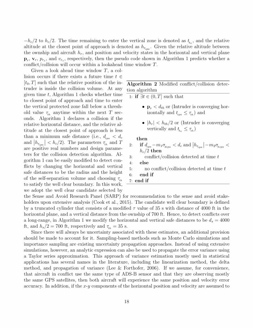
, respectively, then the pseudo code shown in Algorithm 1 predicts whether aconflict/collision will occur within a lookahead time window T .
Algorithm 2 Modified conflict/collision detec-tion algorithm1: if 9t 2 (0, T ] such that
• pr
< d
th
or (Intruder is converging hor-izontally and t
cpa
⌧
th
) and
• |h
r
| < h
th
/2 or (Intruder is convergingvertically and t
h
c
⌧
th
)
then2: if d
cpa
�m1�dcpa
< d
c
and��h
r
cpa
���m2�
hcpa
<
h
c
/2 then3: conflict/collision detected at time t
4: else5: no conflict/collision detected at time t
6: end if7: end if
Given a look ahead time window T , a col-lision occurs if there exists a future time t 2
[t0, T ] such that the relative position of the in-truder is inside the collision volume. At anygiven time t, Algorithm 1 checks whether timeto closest point of approach and time to enterthe vertical protected zone fall below a thresh-old value ⌧
th
anytime within the next T sec-onds. Algorithm 1 declares a collision if therelative horizontal distance, and the relative al-titude at the closest point of approach is lessthan a minimum safe distance (i.e., d
cpa
< d
c
and��h
r
cpa
��< h
c
/2). The parameters ⌧th
and T
are positive real numbers and design parame-ters for the collision detection algorithm. Al-gorithm 1 can be easily modified to detect con-flicts by changing the horizontal and verticalsafe distances to be the radius and the heightof the self-separation volume and choosing ⌧
th
to satisfy the well clear boundary. In this work,we adopt the well clear candidate selected bythe Sense and Avoid Research Panel (SARP) for recommendation to the sense and avoid stake-holders upon extensive analysis (Cook et al., 2015). The candidate well clear boundary is definedby a truncated cylinder that consists of a modified ⌧ value of 35 s with distance of 4000 ft in thehorizontal plane, and a vertical distance from the ownship of 700 ft. Hence, to detect conflicts overa long-range, in Algorithm 1 we modify the horizontal and vertical safe distances to be d
s
= 4000ft, and h
s
/2 = 700 ft, respectively and ⌧
th
= 35 s.Since there will always be uncertainty associated with these estimates, an additional provision
should be made to account for it. Sampling-based methods such as Monte Carlo simulations andimportance sampling are existing uncertainty propagation approaches. Instead of using extensivesimulations, however, an analytic expression can also be used to propagate the error variance usinga Taylor series approximation. This approach of variance estimation mostly used in statisticalapplications has several names in the literature, including the linearization method, the deltamethod, and propagation of variance (Lee & Forthofer, 2006). If we assume, for convenience,that aircraft in conflict use the same type of ADS-B sensor and that they are observing mostlythe same GPS satellites, then both aircraft will experience the same position and velocity erroraccuracy. In addition, if the x-y components of the horizontal position and velocity are assumed to
18
be independent random variables, then the error variances of the horizontal position and velocitymeasurements denoted as �
p
and �
v
, respectively are the same for both aircraft. It can then beshown that the variance of the distance at CPA is �2
dcpa
= 2�2p
+ 2tcpa
�
2v
(Krozel, 1997). Similarly,if the error variances of the vertical velocity and altitude measurements denoted as �
h
and �
v
z
areindependent and the same for both aircraft, then the variance of relative vertical altitude at CPAis �2
hcpa
= 2�2hr
+ 2tcpa
�
2v
rz
. Therefore, Algorithm 1 is modified to become Algorithm 2 to accountfor uncertainties in the ownship and intruder states. In Algorithm 2, m1,m2 are design parametersfor the conflict/collision detection algorithm and are constrained to be positive integers.
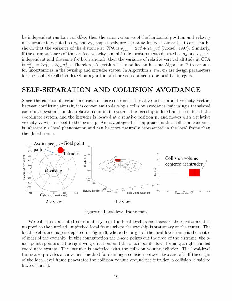
SELF-SEPARATION AND COLLISION AVOIDANCE
Since the collision-detection metrics are derived from the relative position and velocity vectorsbetween conflicting aircraft, it is convenient to develop a collision avoidance logic using a translatedcoordinate system. In this relative coordinate system, the ownship is fixed at the center of thecoordinate system, and the intruder is located at a relative position p
r
and moves with a relativevelocity v
r
with respect to the ownship. An advantage of this approach is that collision avoidanceis inherently a local phenomenon and can be more naturally represented in the local frame thanthe global frame.
0 200 400 600 800 1000 1200-150
-100
-50
0
50
100
150
Heading direction (m)
Hei
ght (
m)
-1000-500
0500
1000
-1000-500
0500
1000-1000
-500
0
500
1000
Right wing direction (m)Heading direction (m)
Hei
ght (
m)
-1000 -500 0 500 1000-1000
-800
-600
-400
-200
0
200
400
600
800
1000
Hea
ding
dire
ctio
n (m
)
Right wing direction (m)
Collision volume centered at intruder
2D view 3D view
Goal point
Ownship
Intruder
Avoidance path
Figure 6: Local-level frame map.
We call this translated coordinate system the local-level frame because the environment ismapped to the unrolled, unpitched local frame where the ownship is stationary at the center. Thelocal-level frame map is depicted in Figure 6, where the origin of the local-level frame is the centerof mass of the ownship. In this configuration the x-axis points out the nose of the airframe, the y-axis points points out the right wing direction, and the z-axis points down forming a right handedcoordinate system. The intruder is encircled with the collision volume cylinder. The local-levelframe also provides a convenient method for defining a collision between two aircraft. If the originof the local-level frame penetrates the collision volume around the intruder, a collision is said tohave occurred.
19
-1000 -500 0 500 1000-1000
-800
-600
-400
-200
0
200
400
600
800
1000
Hea
ding
dire
ctio
n (m
)
Right wing direction (m)
Goal pointIntruder
*
Top view Side view
Climb maneuver
Descend maneuver
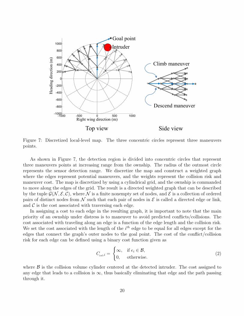
Figure 7: Discretized local-level map. The three concentric circles represent three maneuverspoints.
As shown in Figure 7, the detection region is divided into concentric circles that representthree maneuvers points at increasing range from the ownship. The radius of the outmost circlerepresents the sensor detection range. We discretize the map and construct a weighted graphwhere the edges represent potential maneuvers, and the weights represent the collision risk andmaneuver cost. The map is discretized by using a cylindrical grid, and the ownship is commandedto move along the edges of the grid. The result is a directed weighted graph that can be describedby the tuple G(N , E , C), where N is a finite nonempty set of nodes, and E is a collection of orderedpairs of distinct nodes from N such that each pair of nodes in E is called a directed edge or link,and C is the cost associated with traversing each edge.
In assigning a cost to each edge in the resulting graph, it is important to note that the mainpriority of an ownship under distress is to maneuver to avoid predicted conflicts/collisions. Thecost associated with traveling along an edge is a function of the edge length and the collision risk.We set the cost associated with the length of the i
th edge to be equal for all edges except for theedges that connect the graph’s outer nodes to the goal point. The cost of the conflict/collisionrisk for each edge can be defined using a binary cost function given as
C
col
,i
=
(1, if e
i
2 B,
0, otherwise.(2)
where B is the collision volume cylinder centered at the detected intruder. The cost assigned toany edge that leads to a collision is 1, thus basically eliminating that edge and the path passingthrough it.
20

To provide an increased level of safety, an additional cost is used to penalize edges close to thecollision volume even if they are not within the collision volume. Assuming a constant-velocitymodel, a linear extrapolation of the current position and velocity of the detected intruders iscomputed at evenly spaced time instants over the look-ahead time window. The look-ahead timeinterval is then discretized into several discrete time instants. At each discrete time instant thedistances from the propagated locations of the intruders to all candidate locations of the ownshipat that time instant. The cost of each edge is then the sum of the reciprocal of the associateddistances to each intruder. Dijkstra’s algorithm is then employed to find the path with minimalcost from the start point to the goal point. Dijkstra’s algorithm solves the problem of findingthe shortest path in a directed graph in polynomial time given that there are no negative weightsassigned to the edges. The output of the local-level collision avoidance algorithm generates awaypoint avoidance path that consists of an ordered sequence of waypoints W = w1, w2, · · · .wi
.These waypoints are basically nodes in the discretized local-level graph selected by the Dijkstra’ssearch.
A key feature of the proposed approach is that the future motion of the ownship is constrainedto follow nodes on the map that are spaced by a constant time. Since the path is represented usingwaypoints that are at fixed time instants, it is easy to determine roughly where the ownship willbe at any given time. This timing information can be used when assigning cost to edges to betterplan paths and prevent collisions. To handle conflicts at long-range, the resolution algorithmshould plan smooth maneuvers. This can be achieved by increasing the resolution of discretizedmap or by using smooth path parameterizations like Dubins paths.
SIMULATION RESULTS
To validate the performance of the presented ADS-B sensor model, estimation scheme, con-flict/collision detection, and self-separation/avoidance approaches, we conducted two separatesets of Monte Carlo simulations to address encounter scenarios over short and long ranges. Wedeveloped a simulation environment with a five-degree-of-freedom aircraft model for both the own-ship and the intruders. The state estimates of the intruders are provided by the ADS-B sensor,while we assume a perfect knowledge of the ownship states. To avoid simulating encounters thatare unlikely to result in a collision or loss of self-separation, we focus on encounters that occurin an encounter circle centered on the ownship. The encounter geometry is constructed using anapproach similar to that suggested by Kochenderfer, et al. (Kochenderfer, Kuchar, Espindle, &Gri�th, 2008). The encounter circles used for simulating short and long range encounter scenarioshave radii of 1.62 nmi and 10 nmi respectively. For both sets of Monte Carlo simulations, theownship is initialized at the center of the encounter circle and follows a straight-line waypointpath. The ownship initial heading is zero, and the initial airspeed is set to 80 kn, which is similarto the maximum airspeed of the ScanEagle UAS. At the beginning of each simulation, the firstintruder is initialized at one of 20 evenly spaced points on the perimeter of the encounter circle,while other intruders are initialized by sampling a uniform distribution over the remaining points.In addition, the intruders are initialized with random headings that are required to penetrate theencounter region at the initial time. The speed of the intruders is randomly drawn from a uniform
21
42
69
111
156
204
42
69
110
156
204
0 0 1 0 016
4 7 80 0 0 0 00
25
50
75
100
125
150
175
200
225
1 2 3 4 5
Num
ber o
f Eve
nts
Number of Intruders
Conflict Detection TrueConflict Detection CorrectMissed DetectionsFalse AlarmsLoss of Self-Separation
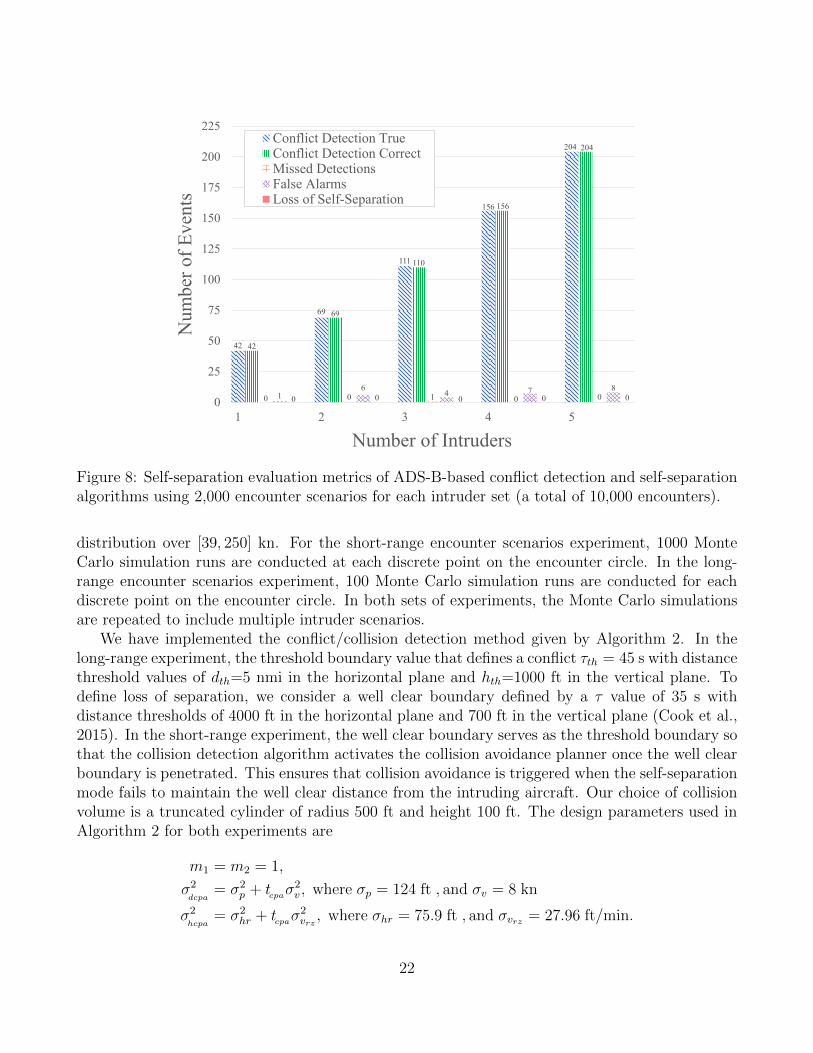
Figure 8: Self-separation evaluation metrics of ADS-B-based conflict detection and self-separationalgorithms using 2,000 encounter scenarios for each intruder set (a total of 10,000 encounters).
distribution over [39, 250] kn. For the short-range encounter scenarios experiment, 1000 MonteCarlo simulation runs are conducted at each discrete point on the encounter circle. In the long-range encounter scenarios experiment, 100 Monte Carlo simulation runs are conducted for eachdiscrete point on the encounter circle. In both sets of experiments, the Monte Carlo simulationsare repeated to include multiple intruder scenarios.
We have implemented the conflict/collision detection method given by Algorithm 2. In thelong-range experiment, the threshold boundary value that defines a conflict ⌧
th
= 45 s with distancethreshold values of d
th
=5 nmi in the horizontal plane and h
th
=1000 ft in the vertical plane. Todefine loss of separation, we consider a well clear boundary defined by a ⌧ value of 35 s withdistance thresholds of 4000 ft in the horizontal plane and 700 ft in the vertical plane (Cook et al.,2015). In the short-range experiment, the well clear boundary serves as the threshold boundary sothat the collision detection algorithm activates the collision avoidance planner once the well clearboundary is penetrated. This ensures that collision avoidance is triggered when the self-separationmode fails to maintain the well clear distance from the intruding aircraft. Our choice of collisionvolume is a truncated cylinder of radius 500 ft and height 100 ft. The design parameters used inAlgorithm 2 for both experiments are
m1 = m2 = 1,
�
2dcpa
= �
2p
+ t
cpa
�
2v
, where �p
= 124 ft , and �
v
= 8 kn
�
2hcpa
= �
2hr
+ t
cpa
�
2v
rz
, where �hr
= 75.9 ft , and �
v
rz
= 27.96 ft/min.
22
415
795
1194
1514
1928
414
790
1191
1505
1911
1 5 3 9 1742 82 124162
221
0 1 2 4 100
250
500
750
1,000
1,250
1,500
1,750
2,000
2,250
1 2 3 4 5
Num
ber o
f Eve
nts
Number of Intruders
Collision Detection TrueCollision Detection CorrectMissed DetectionsFalse AlarmsCollisions
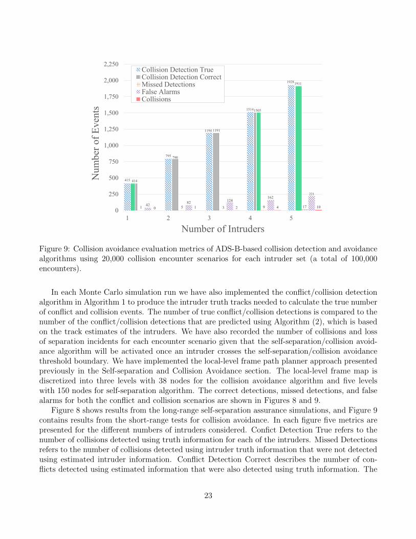
Figure 9: Collision avoidance evaluation metrics of ADS-B-based collision detection and avoidancealgorithms using 20,000 collision encounter scenarios for each intruder set (a total of 100,000encounters).
In each Monte Carlo simulation run we have also implemented the conflict/collision detectionalgorithm in Algorithm 1 to produce the intruder truth tracks needed to calculate the true numberof conflict and collision events. The number of true conflict/collision detections is compared to thenumber of the conflict/collision detections that are predicted using Algorithm (2), which is basedon the track estimates of the intruders. We have also recorded the number of collisions and lossof separation incidents for each encounter scenario given that the self-separation/collision avoid-ance algorithm will be activated once an intruder crosses the self-separation/collision avoidancethreshold boundary. We have implemented the local-level frame path planner approach presentedpreviously in the Self-separation and Collision Avoidance section. The local-level frame map isdiscretized into three levels with 38 nodes for the collision avoidance algorithm and five levelswith 150 nodes for self-separation algorithm. The correct detections, missed detections, and falsealarms for both the conflict and collision scenarios are shown in Figures 8 and 9.
Figure 8 shows results from the long-range self-separation assurance simulations, and Figure 9contains results from the short-range tests for collision avoidance. In each figure five metrics arepresented for the di↵erent numbers of intruders considered. Confict Detection True refers to thenumber of collisions detected using truth information for each of the intruders. Missed Detectionsrefers to the number of collisions detected using intruder truth information that were not detectedusing estimated intruder information. Conflict Detection Correct describes the number of con-flicts detected using estimated information that were also detected using truth information. The
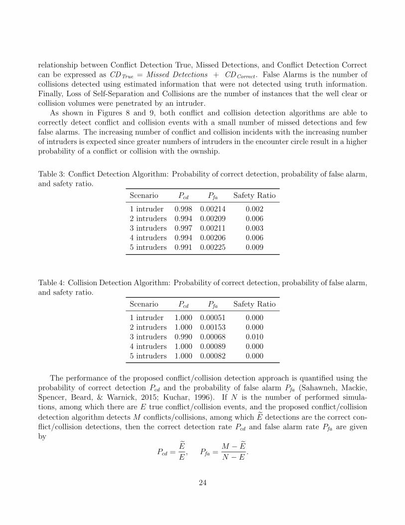
23
relationship between Conflict Detection True, Missed Detections, and Conflict Detection Correctcan be expressed as CD
True
= Missed Detections + CDCorrect
. False Alarms is the number ofcollisions detected using estimated information that were not detected using truth information.Finally, Loss of Self-Separation and Collisions are the number of instances that the well clear orcollision volumes were penetrated by an intruder.
As shown in Figures 8 and 9, both conflict and collision detection algorithms are able tocorrectly detect conflict and collision events with a small number of missed detections and fewfalse alarms. The increasing number of conflict and collision incidents with the increasing numberof intruders is expected since greater numbers of intruders in the encounter circle result in a higherprobability of a conflict or collision with the ownship.
Table 3: Conflict Detection Algorithm: Probability of correct detection, probability of false alarm,and safety ratio.
Scenario P
cd
P
fa
Safety Ratio
1 intruder 0.998 0.00214 0.0022 intruders 0.994 0.00209 0.0063 intruders 0.997 0.00211 0.0034 intruders 0.994 0.00206 0.0065 intruders 0.991 0.00225 0.009
Table 4: Collision Detection Algorithm: Probability of correct detection, probability of false alarm,and safety ratio.
Scenario P
cd
P
fa
Safety Ratio
1 intruder 1.000 0.00051 0.0002 intruders 1.000 0.00153 0.0003 intruders 0.990 0.00068 0.0104 intruders 1.000 0.00089 0.0005 intruders 1.000 0.00082 0.000
The performance of the proposed conflict/collision detection approach is quantified using theprobability of correct detection P
cd
and the probability of false alarm P
fa
(Sahawneh, Mackie,Spencer, Beard, & Warnick, 2015; Kuchar, 1996). If N is the number of performed simula-tions, among which there are E true conflict/collision events, and the proposed conflict/collisiondetection algorithm detects M conflicts/collisions, among which e
E detections are the correct con-flict/collision detections, then the correct detection rate P
cd
and false alarm rate P
fa
are givenby
P
cd
=eE
E
, P
fa
=M �
eE
N � E
.
24

We further quantify the system performance by computing the safety ratio (Kuchar, 1996)
Safety ratio =1� P
cd
1� P
fa
.
The P
cd
and P
fa
results for both collision and conflict detection are shown in Tables 3 and 4. Anideal conflict/collision detection algorithm would result in P
fa
= 0 and P
cd
= 1, with all con-flicts/collisions threats correctly detected and no false alarms. This corresponds to the theoreticalideal point (P
fa
, P
cd
) =(0,1) in signal detection theory. Unfortunately, due to uncertainty in theintruder state estimates, this ideal is not achievable. The closer the value of (P
fa
, P
cd
) to the point(0,1), however, the better the detection performance. In addition, a safety ratio of 0 indicatesthat the detection system provides perfect protection from loss of separation/collision incidents.A safety ratio of 1, however, indicates that the detection system provides no additional protectionfrom loss of separation/collision incidents. The results shown in Tables 3 and 4 demonstrate thatour approach produces results near the ideal operation point (P
fa
, P
cd
) =(0,1) with a safety ratiothat is near zero.
Table 5: Conflict Detection Algorithm: Event detection time delay.
Scenario Average max. 95th Max.time delay (s) percentile time delay (s)
1 intruder 1.389 11.280 12.92 intruders 1.308 8.900 13.73 intruders 1.370 8.160 24.94 intruders 1.444 6.255 36.95 intruders 1.148 5.200 18.9
Table 6: Collision Detection Algorithm: Event detection time delay.
Scenario Average max. 95th Max.time delay (s) percentile time delay (s)
1 intruder 2.010 9.990 18.22 intruders 2.348 9.900 31.93 intruders 2.219 9.900 35.94 intruders 2.354 10.245 31.95 intruders 2.190 9.900 28.5
The conflict/collision detection algorithm can be also evaluated by measuring the time delaybetween a conflict/collision event that has been detected using the intruder truth information,and the time instant at which the proposed conflict/collision detection algorithm is able to detectthe same event using estimated intruder information. Ideally, the time delay should be zero. Due
25
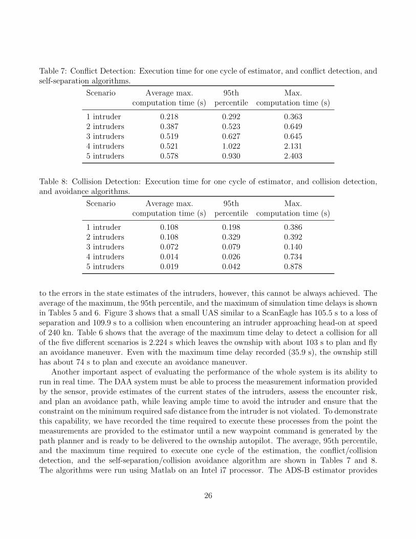
Table 7: Conflict Detection: Execution time for one cycle of estimator, and conflict detection, andself-separation algorithms.
Scenario Average max. 95th Max.computation time (s) percentile computation time (s)
1 intruder 0.218 0.292 0.3632 intruders 0.387 0.523 0.6493 intruders 0.519 0.627 0.6454 intruders 0.521 1.022 2.1315 intruders 0.578 0.930 2.403
Table 8: Collision Detection: Execution time for one cycle of estimator, and collision detection,and avoidance algorithms.
Scenario Average max. 95th Max.computation time (s) percentile computation time (s)
1 intruder 0.108 0.198 0.3862 intruders 0.108 0.329 0.3923 intruders 0.072 0.079 0.1404 intruders 0.014 0.026 0.7345 intruders 0.019 0.042 0.878
to the errors in the state estimates of the intruders, however, this cannot be always achieved. Theaverage of the maximum, the 95th percentile, and the maximum of simulation time delays is shownin Tables 5 and 6. Figure 3 shows that a small UAS similar to a ScanEagle has 105.5 s to a loss ofseparation and 109.9 s to a collision when encountering an intruder approaching head-on at speedof 240 kn. Table 6 shows that the average of the maximum time delay to detect a collision for allof the five di↵erent scenarios is 2.224 s which leaves the ownship with about 103 s to plan and flyan avoidance maneuver. Even with the maximum time delay recorded (35.9 s), the ownship stillhas about 74 s to plan and execute an avoidance maneuver.
Another important aspect of evaluating the performance of the whole system is its ability torun in real time. The DAA system must be able to process the measurement information providedby the sensor, provide estimates of the current states of the intruders, assess the encounter risk,and plan an avoidance path, while leaving ample time to avoid the intruder and ensure that theconstraint on the minimum required safe distance from the intruder is not violated. To demonstratethis capability, we have recorded the time required to execute these processes from the point themeasurements are provided to the estimator until a new waypoint command is generated by thepath planner and is ready to be delivered to the ownship autopilot. The average, 95th percentile,and the maximum time required to execute one cycle of the estimation, the conflict/collisiondetection, and the self-separation/collision avoidance algorithm are shown in Tables 7 and 8.The algorithms were run using Matlab on an Intel i7 processor. The ADS-B estimator provides
26

estimates at a sample rate of 0.1 s. To process all of the estimator data, the other algorithmsshould operate at the same sample rate. Table 7 shows that the average of the maximum runtime to execute the estimator, conflict detection, and the self-separation algorithms is 0.445 s, andthe maximum recorded run time is 2.403 s. Similarly, in Table 8 the average of the maximumrun time of the estimator, collision detection, and avoidance algorithms for all of the five di↵erentscenarios is 0.064 s, while the maximum recorded run time is 0.878 s. Although the recorded runtimes are larger than the 0.1 s, these algorithms are running near real time in Matlab. We expectthat implementing these algorithms in a compiled language, such as C or C++, will show thatreal-time execution is feasible using low-cost computational hardware.
In these experiments, the collision volume is large (500 ft radius, 100 ft height) compared tothe size of the ownship aircraft. If the collision volume were reduced to more closely reflect theaircraft size, the number of collisions detected drops even further. For example, Figure 9 showsa total number of 10 collisions out of the 1928 potential collisions detected using intruder truthinformation for the five intruder scenario case. If the collision volume is reduced to a third of theoriginal size, then the number of collisions decreases to only one. If the collision volume is furtherreduced to a cylinder of radius 10 ft, approximating the wingspan of a small UAS, and height of 3ft, we record zero collisions. From this we can conclude that none of these collision incidents wereactual collisions, but only a violation of the surrounding collision volume.
CONCLUSIONS
We have introduced in this paper an ADS-B-based collision detection and avoidance approach thatis computationally feasible for small UAS. Taking advantage of the long-range detection o↵eredby the ADS-B system, the proposed approach is used to detect conflict events over the range of 5to 10 nmi, and consequently provide self-separation of the host ownship.
The results from Monte Carlo simulations show that the proposed system supports a high levelof safety. In the 10,000 executed self-separation simulations, well clear was fully maintained. Forthe 100,000 collision scenarios, the number of collision-volume violations was only 17, with nophysical collisions occuring. The run-time results also indicate that the estimation scheme, detec-tion method, and avoidance logic are capable of running in near real time in Matlab. Consideringthe increase in computational e�ciency that would result from a compiled-code implementationof the algorithm, real-time execution can be easily achieved.
A key result of this paper is that it demonstrates that mandating ADS-B Out equipage for allaircraft could play a significant role in the safe integration of UAS into the NAS. The theoreticalbasis and positive simulation results presented here demonstrate the feasibility of the proposedsystem. While the FAA 2020 mandate for ADS-B includes only some aircraft, requiring all aircraftto have ADS-B Out would create a suitable environment for implementation of ADS-B-based DAA.Ultimately, the combination of complete ADS-B equipage and DAA system like the one presentedhere would be a major step toward allowing UAS to safely operate in the NAS with mannedaircraft.
27

ACKNOWLEGMENTS
This research was conducted in the NSF Center for Unmanned Aircraft Systems (C-UAS) withsupport from National Science Foundation I/UCRC program grant number IIP-1171036 and C-UAS industry members.
REFERENCES
Albaker, B. M., & Rahim, N. A. (2010). Unmanned Aircraft Collision Detection and Resolution:Concept and Survey. 2010 5th IEEE Conference on Industrial Electronics and Applications ,248–253.
Angelov, P. (2012). Sense and Avoid in UAS: Research and Applications. John Wiley & Sons,Ltd.
Beard, R., & McLain, T. (2012). Small Unmanned Aircraft: Theory and Practice. PrincetonUniversity Press.
Boskovic, J. D., Jackson, J. A., & Mehra, R. k. (2013, Sep). Sensor and Tracker RequirementsDevelopment for Sense and Avoid Systems for Unmanned Aerial Vehicles. In AIAA Modelingand Simulation Technologies (MST) Conference. Boston, MA.
Cirillo, M. (2005). Air Tra�c Bulletin: New Technology - ADS-B, TIS-B, and FIS-B (No.2005-3).
Cole, R., Kochenderfer, M. J., Weibel, R., Edwards, M. W. M., Gri�th, J. D., & Olson, W. (2013).Fielding a Sense and Avoid Capability for Unmanned Aircraft Systems: Policy, Standards,Technology, and Safety Modeling. Air Tra�c Control Quarterly, special Issue on UnmannedAircraft Systems , 21 (1), 5-27.
Collision Avoidance Functional Requirements for Step 1 (Tech. Rep.). (2006, Feb.). Edwards,CA: NASA.
Consiglio, M., Carreno, V., & Williams, D. (2005). Conflict Prevention and Separation Assur-ance Method in Small Aircraft Transportation System. In AIAA 5th Aviation, Technology,Integration, and Operations Conference (ATIO). Arlington, Virginia.
Consiglio, M., Chamberlain, J., Munoz, C., & Ho✏er, K. (2012). Concept of Integration ForUAS Operations in The NAS. In 28th International Congress of the Aeronautical Sciences(ICAS). Brisbane, Australia.
Cook, S. P., Brooks, D., Cole, R., Hackenberg, D., & Raska, V. (2015, January). Defining WellClear for Unmanned Aircraft Systems. In AIAA Infotech @ Aerospace. Kissimmee, Florida:AIAA.
Dey, D., Geyer, C., Singh, S., & Digioia, M. (2009). Passive, Long-range Detection of Aircraft :Towards a Field Deployable Sense and Avoid System. In Field & Service Robotics.
Dijkstra, E. W. (1959). A Note On Two Problems In Connection With Graphs. NumerischeMathematik , 1 , 269-271.
FAA Modernization and Reform Act of 2012. (2014).Federal Aviation Administration. (2010a). Advisory Circular 20-165: Airworthiness Approval of
Automatic Dependent Surveillance - Broadcast (ADS-B) Out Systems.
28
Federal Aviation Administration. (2010b). Automatic Dependent Surveillance Broadcast (ADSB)Out Performance Requirements To Support Air Tra�c Control (ATC) Service.
Federal Aviation Administration. (2012). Advisory Circular 90-114: Automatic DependentSurveillance-Broadcast (ADS-B) Operations.
Federal Aviation Administration. (2015). Subchapter F - Air Tra�c and General Operating Rules.George, S. (2009). FAA Workshop on Sense and Avoid (SAA) for Unmanned Aircraft Systems
(UAS).Geser, A., & Muoz, C. (2002). A Geometric Approach to Strategic Conflict Detection And
Resolution. In Proceedings of the 21st IEEE Digital Avionics Systems Conference (Vol. 1).Geyer, C., Singh, S., & Chamberlain, L. (2008). Avoiding Collisions Between Aircraft: State of
the Art and Requirements for UAVs operating in Civilian Airspace (Tech. Rep.).Hottman, S., Hansen, K., & Berry, M. (2009). Literature Review on Detect, Sense, and Avoid
Technology for Unmanned Aircraft Systems (Tech. Rep.).Hu, J., Lygeros, J., Prandini, M., & Sastry, S. (1999). Aircraft Conflict Prediction and Resolution
Using Brownian Motion. In Proceedings of the 38th Conference on Decision & Control.Phoenix.
Hyunjin, Y. K., Choi. (2013). Reactive Collision Avoidance of Unmanned Aerial Vehicles Usinga Single Vision Sensor. AIAA Guidance, Control, and Dynamics , 36 (4), 1234-1240.
Jackson, J., & Boskovic, J. (2012, August). Application of Airspace Encounter Model for Pre-diction of Intruder Dynamics. In AIAA Modeling and Simulation Technologies Conference.AIAA.
Kavraki, L. E., Svestka, P., Latombe, J. C., & Overmars, M. H. (1996). Probabilistic Roadmapsfor Path Planning in High-dimensional Configuration Spaces. IEEE Transactions on onRobotics and Automation, 12 (4), 566-580.
Kochenderfer, M. J., Kuchar, J. K., Espindle, L. P., & Gri�th, J. D. (2008). UncorrelatedEncounter Model of the National Airspace System Version 1.0 (Tech. Rep.). LincolnLaboratory-Masschusetts Institute of Technology.
Kothari, M., & Postlethwaite, I. (2013). A Probabilistically Robust Path Planning Algorithm forUAVs Using Rapidly-Exploring Random Trees. International Robotic Systems , 71 , 231-253.
Krozel, J. (1997). Strategic Conflict Detection and Resolution for Free Flight Il. , 1822–1828.Krozel, J., Andrisani, D., Ayoubi, M. A., Hoshizaki, T., & Schwalm, C. (2004). Aircraft ADS-B
Data Integrity Check. , 1–11.Kuchar, J. K. (1996). Methodology for Alerting-System Performance Evaluation. Guidance,
Control, and Dynamics , 19 (2), 438-444.Kuchar, J. K., & Yang, L. C. (2000, December). A Review of Conflict Detection and Resolution
Modeling Methods. IEEE Transactions on Intelligent Transportation Systems , 1 (4), 179–189.
Lai, C., Ren, Y.-j., & Lin, C. (2009). ADS-B Based Collision Avoidance Radar for UnmannedAerial Vehicles. In Ieee 2009 microwave symposium digest (pp. 85–88).
Lai, J., Ford, J. J., Mejias, L., Shea, P. O., & Walker, R. (2012). See and Avoid Using OnboardComputer Vision. In Sense and Avoid in UAS: Research and Applications (pp. 265–294).
Lam, T. M., Mulder, M., Van Paassen, M. M., Mulder, J. A., & Van Der Helm, F. C. (2009). Force-
29

Sti↵ness Feedback in Uninhabited Aerial Vehicle Teleoperation with Time Delay. AIAAGuidance, Control, and Dynamics , 32 (3), 821-835.
LaValle, S. M. (1998). Rapidly-Exploring Random Trees: A New Tool for Path Planning. Retrievedfrom http://msl.cs.uiuc.edu/
~
lavalle/rrtpubs.html
Lee, E. S., & Forthofer, R. N. (2006). Analyzing Complex Survey Data (Second ed.). ThousandOaks, CA.: Sage Publications, Inc.
Luders, B., Karaman, S., Frazzoli, E., & How, J. P. (2010). Bounds on Tracking Error usingClosed-Loop Rapidly-Exploring Random Trees. In American Control Conference. Baltimore,MD.
Luders, B., Karaman, S., & How, J. P. (2013). Robust Sampling-based Motion Planning withAsymptotic Optimality Guarantees. In Guidance, Navigation, and Control (GNC) Confer-ence. Boston, MA.
Mackie, J., Spencer, J., &Warnick, K. (2014). Compact FMCWRadar for GPS-Denied Navigationand Sense and Avoid. In IEEE Antennas and Propagation Society, AP-S InternationalSymposium (pp. 989–990).
Mehrotra, K., & Mahapatra, P. R. (1997). A Jerk Model for Tracking Highly ManeuveringTargets. IEEE Transactions on Aerospace and Electronic Systems , 33 (4), 1094–1105. doi:10.1109/7.624345
Mirolo, C., & Pagello, E. (1995). A Cell Decomposition Approach to Motion Planning Basedon Collision Detection. In Proceedings of the 1995 International Conference on AdvancedRobotics (p. 481-488).
Mohleji, S. C., & Wang, G. (2010). Modeling ADS-B Position and Velocity Errors for AirborneMerging and Spacing in Interval Management Application (Tech. Rep.). McLean, VA: Centerfor Advanced Aviation System Development.
Moody, C., & Strain, R. (2009, April). Implementation Consideration for Automatic DependentSurveillance - Broadcast on Unmanned Aircraft Systems. In AIAA Infotech@AerospaceConference (pp. 1–8). Reston, Virigina. doi: 10.2514/6.2009-1865
Munoz, C., Narkawicz, A., & Chamberlain, J. (2013). A TCAS-II Resolution Advisory Algorithm.In Proceedings of the AIAA Guidance, Navigation, and Control Conference. Boston, MA.
Paielli, R. A., & Erzberger, H. (1997). Conflict Probability Estimation for Free Flight. AIAAGuidance, Control, and Dynamics , 20 (3), 588-596.
Papoulis, A., & Pillai, S. U. (2002). Probability, Random Variables, and Stochastic Processes(Fourth ed.). McGraw-Hill New York.
Prandini, M., Hu, J., Lygeros, J., & Sastry, S. (2000). A Probabilistic Approach to AircraftConflict Detection. IEEE Transactions on Inteliget Transportation Systms , 1 (4), 199-220.
Radio Technical Commision for Aeronautics. (2003). Minimum Aviation System PerformanceStandards for Aircraft Surveillance Applications.
Radio Technical Commision for Aeronautics. (2009). DO-282B Minimum Operational PerformanceStandards for Universal Access Transceiver ( UAT ) Automatic Dependent Surveillance -Broadcast ( ADS-B ) DRAFT Final Review and Comment (No. 190).
Radio Technical Commision for Aeronautics. (2011). DO-260B Minimum Operational PerformanceStandards for 1090 MHz Extended Squitter Automatic Dependent Surveillance Broadcast (
30

ADS-B ) and Tra�c Information Services Broadcast ( TIS-B ).Rajnikant, S., Saunders, J. B., & Beard W., R. (2012). Reactive Path Planning for Micro Air
Vehicles Using Bearing-only Measurements. International Robotic Systems , Volume 65 (1-4),409-416.
SAE International. (1996). AS8002A Air Data Computer - Minimum Performance Standard.Sahawneh, L. R., Mackie, J., Spencer, J., Beard, R. W., & Warnick, K. F. (2015). Airborne
Radar-Based Collision Detection and Risk Estimation for Small Unmanned Aircraft Systems.Aerospace Information Systems , 0 (0), Ahead of Print: 1-11.
Sahawneh, L. R., Randal W. Beard, S. A., & Bai, H. (2013). Chain-based Collision Avoidancefor UAS Sense and Avoid Systems. In Proceedings of the AIAA Guidance, Navigation andControl Conference.
Unmanned Aircraft System (UAS) Service Demand 2015-2035 (Tech. Rep.). (2013). U.S.Department of Transportation. Retrieved from http://fas.org/irp/program/collect/
service.pdf
van Daalen, C., & Jones, T. (2009). Fast Conflict Detection Using Probability Flow. Automatica,45 , 1903-1909.
BIOGRAPHIES
Laith R. Sahawneh is currently a Ph.D. candidate and a research assistant in the Electrical andComputer Engineering Department at Brigham Young University. His current research focuseson collision prediction, path planning, and detect and avoid for small UAS. He received his M.S.degree in mechatronics engineering in 2009 from the American University of Sharjah, UAE.
Matthew O. Du�eld is graduate student in the Mechanical Engineering Department at BrighamYoung University in Provo, Utah. He is pursuing a joint Master of Science in Mechanical Engi-neering and a Master of Business Administration. His research is focused on the opportunitiesand applications of Automatic Dependent Surveillance-Broadcast for detect and avoid on smallunmanned aircraft. In 2014 he was recognized as a Utah NASA Space Grant Consortium Fellow.Matthew completed his Bachelor of Science degree in Mechanical Engineering at Brigham YoungUniversity in 2014.
Randal W. Beard received a Ph.D. degree in electrical engineering in 1995 from RensselaerPolytechnic Institute. He is currently a professor in the Electrical and Computer EngineeringDepartment at Brigham Young University. His primary research focus is in autonomous systems,unmanned air vehicles, and multiple vehicle coordination and control. He is a fellow of the IEEEand an associate fellow of AIAA. He is a former associate editor for the IEEE Transactions on Au-tomatic Control, the Journal of Intelligent and Robotics Systems, and the IEEE Control SystemsMagazine.
Timothy W. McLain is a professor of mechanical engineering at Brigham Young University.During 1999 and 2000, he was a visiting scientist at the Air Force Research Laboratory where
31

he initiated research in the guidance and control of unmanned aircraft systems. Since then, hisUAS research has attracted the support of the Air Force, the Army, DARPA, NASA, NSF, andONR. He is the author of over 120 peer-reviewed articles. With Randy Beard, he is the author ofthe textbook Small Unmanned Aircraft. He is currently the director of the Center for UnmannedAircraft Systems sponsored by the National Science Foundation.
32
Related Documents