Brassmasters Scale Models www.brassmasters.co.uk Detailing Kit for Bachmann GWR Modified Hall 4-6-0 (suitable only for models produced from 2015 onwards) INSTRUCTIONS PO Box 1137 Sutton Coldfield B76 1FU Copyright Brassmasters 2016

Welcome message from author
This document is posted to help you gain knowledge. Please leave a comment to let me know what you think about it! Share it to your friends and learn new things together.
Transcript

Brassmasters Scale Models
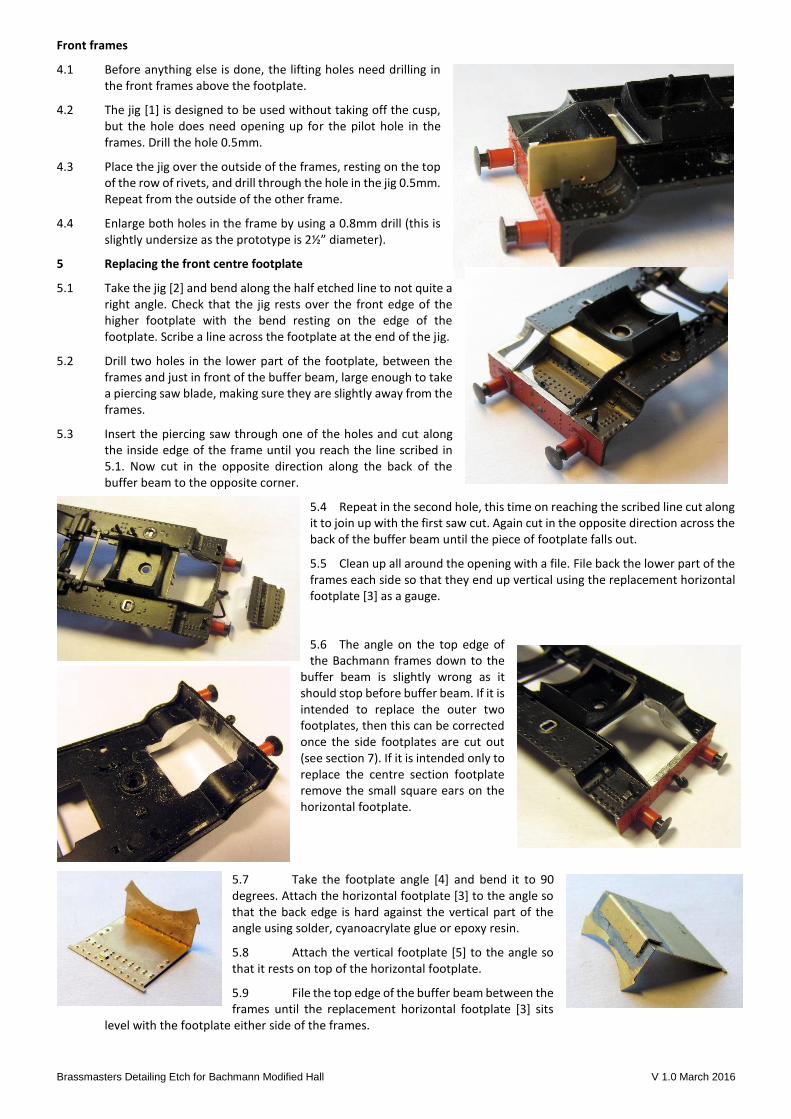
www.brassmasters.co.uk
Detailing Kit for Bachmann GWR Modified Hall 4-6-0
(suitable only for models produced from 2015 onwards)
INSTRUCTIONS
PO Box 1137 Sutton Coldfield B76 1FU Copyright Brassmasters 2016
Brassmasters Detailing Etch for Bachmann Modified Hall v1.0 March 2016
1 Introduction
1.1 The detailing kit was designed to replace the incorrect front footplate of the latest version of Bachmann’s Modified Hall and includes a number of other detailing parts to improve the front end.
1.2 There are a number of options in the detailing kit. These are:
replacement footplate between the front frames replacement curved drop frames dummy front frames below the footplate drilling jig for the lifting holes in the front frame smoke box saddle side plates replacement smokebox footstep replacement front lamp irons stretcher plate and brackets for bogie front.
2 General Notes
2.1 Numbers shown in square brackets [ ] in the instructions refer to the part numbers, e.g., [2]. The part number appears on the separate etch diagrams.
2.2 Some of the parts are small and easily damaged, so do please take care. Parts should be removed from the sheets as and when needed by use of a small scalpel etc., and the tabs and etch cusp removed with a small fine-cut file.
2.3 All folds and bends are made with the half-etched line on the inside unless otherwise stated.
2.4 On some parts it is necessary to emboss rivet / bolt heads from the reverse sides by use of a punch.
2.5 Tools required
A selection of cross head and normal miniature screwdrivers Small pliers Small plastic bags and labels to identify parts and screws when dismantling Small files A steel rule Craft knife Piercing saw Plastic solvent, superglue and epoxy resin (24 hour and 5 minute)
3 Dismantling the locomotive
3.1 In all cases, bag and label all small parts and source of screws as soon as removed (they are all different) - trust us on this one!
3.2 When handling the loco body, be very careful as it is very easy to break off some items.
3.3 Unscrew the front and rear screws that hold the body in place. The front screw is above the bogie, and there are two screws at the rear under the cab.
3.4 Next unscrew the four screws that hold the boiler and cab to the footplate, one under the smokebox, one in front of the leading splashers and two under the cab. Lift the boiler and cab away from the footplate taking care of the cab vertical handrails that will remain with the footplate.
3.5 Remove the outside steam pipes by wriggling them back and forwarded until the glue joint breaks. Prize out the smokebox saddle and, by using a small screwdriver to push up through the slot under the front footplate, remove the oil feed box. Keep them all safe for use later.
3.6 Unscrew the crankpins on the centre driving wheels and remove both connecting rods and crossheads from the slide bars. Unscrew the two screws holding the cylinder block in place.
3.7 Finally unscrew the bogie. This is quite fiddly as you will need two screwdrivers, one on top on the screw and one on the bottom collar, and it is quite stiff. Note these screws require a straight bladed screwdriver. All other screws on the loco are cross head.
3.8 You will now have a box of bits!
3.9 Wash your hands as you will have grease on them from the chassis, and the etches should be kept as clean as possible.
Brassmasters Detailing Etch for Bachmann Modified Hall V 1.0 March 2016
Front frames
4.1 Before anything else is done, the lifting holes need drilling in the front frames above the footplate.
4.2 The jig [1] is designed to be used without taking off the cusp, but the hole does need opening up for the pilot hole in the frames. Drill the hole 0.5mm.
4.3 Place the jig over the outside of the frames, resting on the top of the row of rivets, and drill through the hole in the jig 0.5mm. Repeat from the outside of the other frame.
4.4 Enlarge both holes in the frame by using a 0.8mm drill (this is slightly undersize as the prototype is 2½” diameter).
5 Replacing the front centre footplate
5.1 Take the jig [2] and bend along the half etched line to not quite a right angle. Check that the jig rests over the front edge of the higher footplate with the bend resting on the edge of the footplate. Scribe a line across the footplate at the end of the jig.
5.2 Drill two holes in the lower part of the footplate, between the frames and just in front of the buffer beam, large enough to take a piercing saw blade, making sure they are slightly away from the frames.
5.3 Insert the piercing saw through one of the holes and cut along the inside edge of the frame until you reach the line scribed in 5.1. Now cut in the opposite direction along the back of the buffer beam to the opposite corner.
5.4 Repeat in the second hole, this time on reaching the scribed line cut along it to join up with the first saw cut. Again cut in the opposite direction across the back of the buffer beam until the piece of footplate falls out.
5.5 Clean up all around the opening with a file. File back the lower part of the frames each side so that they end up vertical using the replacement horizontal footplate [3] as a gauge.
5.6 The angle on the top edge of the Bachmann frames down to the
buffer beam is slightly wrong as it should stop before buffer beam. If it is intended to replace the outer two footplates, then this can be corrected once the side footplates are cut out (see section 7). If it is intended only to replace the centre section footplate remove the small square ears on the horizontal footplate.
5.7 Take the footplate angle [4] and bend it to 90 degrees. Attach the horizontal footplate [3] to the angle so that the back edge is hard against the vertical part of the angle using solder, cyanoacrylate glue or epoxy resin.
5.8 Attach the vertical footplate [5] to the angle so that it rests on top of the horizontal footplate.
5.9 File the top edge of the buffer beam between the frames until the replacement horizontal footplate [3] sits
level with the footplate either side of the frames.

Brassmasters Detailing Etch for Bachmann Modified Hall V 1.0 March 2016
5.10 Check that the new footplate assembly fits between the frames and does not overhang the buffer beam more than the curved footplates. File the back edge of the opening in the cast footplate if necessary.
Push through the two rivets in the lamp iron bracket from the back using a point or riveting tool.
5.11 Bend a lamp iron [6] at right angles along the end of the full etched section. Push though the slot in the footplate and attach.
6 Cutting the chassis block
6.1 Take the chassis cutting jig [7] and hold it to the side of the Bachmann chassis block, aligning with the front of the block and the top of the block. Scribe a line along the inner edges of the jig (photo shows gauge in position but with section already cut off).
6.2 Using a hacksaw, cut along the horizontal line, continuing the original horizontal section until the vertical scribe line is met. Then cut down the vertical line until it meets the previous saw cut and the piece of chassis block drops out.
6.3 Clean up the surfaces and edges with a file.
6.4 If only the centre section of footplate is being replaced go to section 8.
7 Replacing the curved side footplates
7.1 Cut out a piece of thin card to the same size as the replacement curved footplates [8] and [9].
7.2 A 5 mm drill or piece of tube is required to curve the footplate. Take the curved footplate [8] and cover the riveted face with the card to protect the rivet detail. Curve the end around drill/tube. There are a number of ways to do this but the etch is thin enough to do it in your fingers. This method won’t complete the curve to the edge of the etch so clamp the etch and drill/tube in the vice and push the last bit over with something flat. Other methods involve clamping in the vice for the initial bend but I find that fiddly. If the initial bend is not quite in the right place or square to the etch, the bend can easily be repositioned by holding the etch in the correct position over the drill/tube and rubbing the back of the etch with your thumb. There are two spare etches in case it goes really wrong, but bending it is even easier than I imagined! Compare the curve with that on the cast footplate. Repeat for the second curved footplate [8].
7.3 Drill a hole in cast footplate outside of the frames large enough to take a piercing saw blade, making sure it is slightly away from the frames and just in front of the buffer beam.
7.4 Insert the piercing saw through the hole and cut along the outside edge of the frame until you reach the front edge of the higher footplate. Do not cut into this edge. Now cut across the front of this edge until the edge of the footplate valance is reached underneath the footplate. From the hole, cut across the footplate behind the buffer beam and then along the inside of the valance to join up with the first cut and the piece of footplate falls out.
7.5 Clean up all around the opening with a file. Do not file back the lower part of the frames each side to make them vertical this time.
7.6 File the top edge of the buffer beam, the top edge of the valance, including the curved section, and the front edge of the higher footplate until the replacement curved footplate sits in place, level with the front edge of the centre footplate, the side edge of the cast higher footplate and the top edge of the higher footplate.
7.7 If the front edge of the frames is to be filed back to the correct angle (see 5.7), file the front edge back at the bottom, using a square file, so that when the horizontal footplate [3] is put in position, the small ears clear the frames and the front edge of the horizontal footplate does not overhang the buffer beam more than the curved footplates. Then file the sloping edge of the frames so that the lower end meets the new footplate.
Brassmasters Detailing Etch for Bachmann Modified Hall V 1.0 March 2016
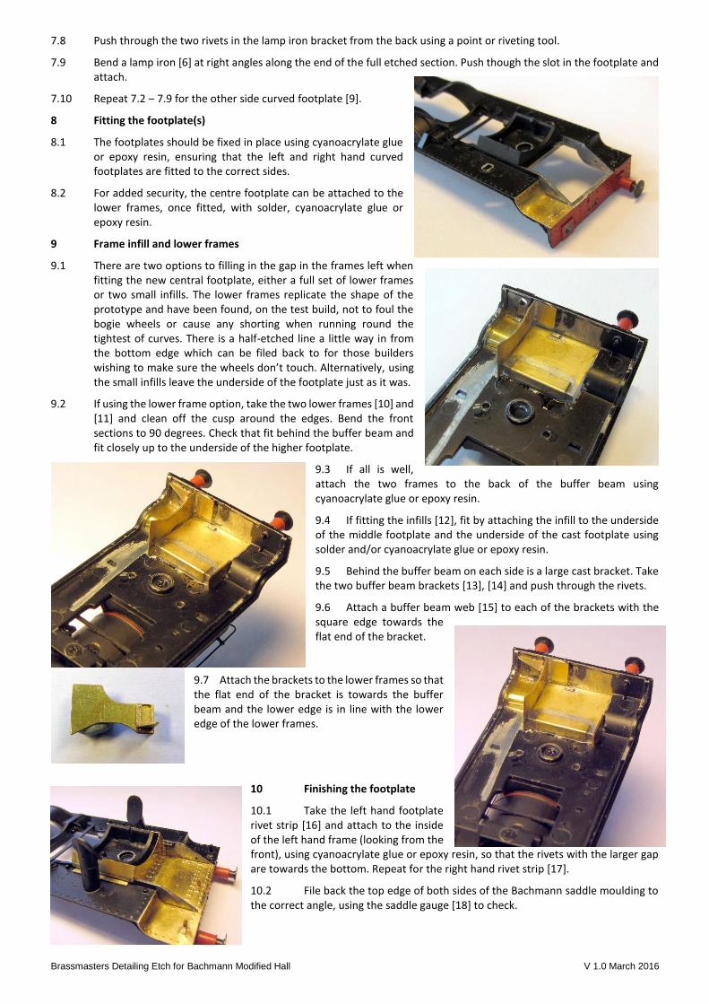
7.8 Push through the two rivets in the lamp iron bracket from the back using a point or riveting tool.
7.9 Bend a lamp iron [6] at right angles along the end of the full etched section. Push though the slot in the footplate and attach.
7.10 Repeat 7.2 – 7.9 for the other side curved footplate [9].
8 Fitting the footplate(s)
8.1 The footplates should be fixed in place using cyanoacrylate glue or epoxy resin, ensuring that the left and right hand curved footplates are fitted to the correct sides.
8.2 For added security, the centre footplate can be attached to the lower frames, once fitted, with solder, cyanoacrylate glue or epoxy resin.
9 Frame infill and lower frames
9.1 There are two options to filling in the gap in the frames left when fitting the new central footplate, either a full set of lower frames or two small infills. The lower frames replicate the shape of the prototype and have been found, on the test build, not to foul the bogie wheels or cause any shorting when running round the tightest of curves. There is a half-etched line a little way in from the bottom edge which can be filed back to for those builders wishing to make sure the wheels don’t touch. Alternatively, using the small infills leave the underside of the footplate just as it was.
9.2 If using the lower frame option, take the two lower frames [10] and [11] and clean off the cusp around the edges. Bend the front sections to 90 degrees. Check that fit behind the buffer beam and fit closely up to the underside of the higher footplate.
9.3 If all is well, attach the two frames to the back of the buffer beam using cyanoacrylate glue or epoxy resin.
9.4 If fitting the infills [12], fit by attaching the infill to the underside of the middle footplate and the underside of the cast footplate using solder and/or cyanoacrylate glue or epoxy resin.
9.5 Behind the buffer beam on each side is a large cast bracket. Take the two buffer beam brackets [13], [14] and push through the rivets.
9.6 Attach a buffer beam web [15] to each of the brackets with the square edge towards the flat end of the bracket.
9.7 Attach the brackets to the lower frames so that the flat end of the bracket is towards the buffer beam and the lower edge is in line with the lower edge of the lower frames.
10 Finishing the footplate
10.1 Take the left hand footplate rivet strip [16] and attach to the inside of the left hand frame (looking from the front), using cyanoacrylate glue or epoxy resin, so that the rivets with the larger gap are towards the bottom. Repeat for the right hand rivet strip [17].
10.2 File back the top edge of both sides of the Bachmann saddle moulding to the correct angle, using the saddle gauge [18] to check.

Brassmasters Detailing Etch for Bachmann Modified Hall V 1.0 March 2016
10.3 Take the two saddle side plates [19] and scribe a line along the back just under 1 mm from the bottom edge (note the bottom edge is the one with fewer rivets on).
10.4 Carefully bend the saddle side plates along the scribed line until they fit on the sides of the saddle moulding (there are spares in case it doesn’t go right).
10.5 Re-attach the smokebox saddle moulding and check that the side plates fit up to the vertical plate. Carry out any slight adjustment by further filing of the saddle moulding.
10.6 Re-fit the boiler to the footplate.
10.7 Attach the two saddle side plates to the saddle using cyanoacrylate glue or epoxy resin, ensuring that the front edge aligns with the vertical part of the middle footplate.
10.8 There is a saddle rear [20] which, if required, can be attached to the saddle side plates in line with their rear edge.
10.9 Attach the two footplate covers [21] to cast footplate, either side the smokebox, against the frame and central to the outside steam pipes, using cyanoacrylate glue or epoxy resin.
11 Modifying the bogie
11.1 There are two versions of the modification to the bogie, using a wide front plate looks better but does involve slightly more work. Both require the front edge between the bogie sideframes to be cut and filed back. We even cut off the top part of the NEM pocket.
Cut and file back the front edge of the bogie between the frames until the wings of the gauge [22] rest against the front edge of the bogie.
11.2 Wide front plate
11.2.1 If using the wide front plate [23], the front part of each plastic side frame needs filing back evenly both sides and as far back as the front edge, using the wide bogie front as a gauge. Square up corner between the sides and the front edge and round off the back corner of the front plate to allow it to sit all the way back. Be careful with the thinned side frames at this point as they are quite vulnerable when handling.
11.2.2 Attach the wide front plate to the front of the bogie using cyanoacrylate glue or epoxy resin, ensuring the plate is vertical and level.
11.2.3 Attach the bogie left side rivet strip [24] (looking from the front) to the plastic side frame butting up against the wide front plate. Then attach the bogie left face rivet strip [25] to the left hand side of the wide front plate butting up against the side rivet strip.

Brassmasters Detailing Etch for Bachmann Modified Hall V 1.0 March 2016
11.2.4 Repeat for the right had side using parts [26] and [27].
11.3 Narrow front plate
11.3.1 If using the narrow front plate [28] attach it to the front of the bogie using cyanoacrylate glue or epoxy resin, ensuring the plate is vertical and level.
11.3.2 Attach the bogie left face rivet strip [25] to the left hand side of the narrow front plate butting up against the plastic side frame (the side rivet strips are not used in this case).
11.3.3 Repeat for the right hand side using part [27].
12 Final detail
12.1 We found it easier to add these details with the boiler separated from the footplate
12.2 Bend the replacement smokebox foot step [29] by gripping the edge in a pair of pliers and bending over to a right angle. Repeat for the other edge.
12.3 Carefully cut and file away the original smokebox step. Attach the replacement with cyanoacrylate glue or epoxy resin.
12.4 Bend up the replacement smokebox lamp bracket [30]. There are small half etch dots to show where the bends should be.
12.5 Carefully remove the original lamp bracket from the smokebox door by pulling with a pair of pliers and attach the replacement lamp iron using cyanoacrylate glue or epoxy resin.
(For a more secure attachment, do not bend up the part of the lamp iron that attaches to the front of the door, but insert it through the original hole and secure with epoxy resin spacing the back of the upright part 2.3 mm from the smoke box front. Cut the vertical part from the spare lamp iron and attach to the smokebox front using cyanoacrylate glue or epoxy resin.)
12.6 Take the plastic lubricator removed in 3.6 and reduce the length at the left hand end by one pipe, then cut off the pipes where they reduce in size below the lubricator.
12.7 Attach to the inside of the right hand frame (looking from the front) with the top level with the top edge of the frame and the left hand edge against the rivet strip, using cyanoacrylate glue or epoxy resin.
12.8 If you have suitable very fine wire, two pipes can be added from the bottom of the lubricator down to the footplate attaching them to the lubricator in the two gaps at the bottom using cyanoacrylate glue or epoxy resin.
13 The loco boiler, footplate, chassis and bogie can now be re-assembled.

Brassmasters Detailing Etch for Bachmann Modified Hall V 1.0 March 2016
Note The model shown below has deliberately been built with the original curved footplate left on one side, and the replacement curved footplate on the other.
Photo showing side without curved frame replacement Photo showing side with curved frame replacement
Etch part numbers
1 frame hole jig 11 lower frame right (looking from front) 21 footplate covers (2)
2 footplate cutting jig 12 infills (2) 22 bogie gauge
3 horizontal footplate 13 buffer beam bracket left (looking from front) 23 wide front plate
4 footplate angle 14 buffer beam bracket right (looking from front) 24 side rivet strip left (looking from front)
5 vertical footplate 15 buffer beam bracket web (2) 25 face rivet strip left (looking from front)
6 lamp iron (3) 16 footplate rivet strip left (looking from front) 26 side rivet strip right (looking from front)
7 chassis cutting jig 17 footplate rivet strip right (looking from front) 27 face rivet strip right (looking from front)
8 curved footplate left (looking from front) 18 saddle gauge 28 narrow front plate
9 curved footplate right (looking from front) 19 saddle side plates (2) 29 smokebox foot step
10 lower frame left (looking from front) 20 saddle rear 30 smokebox lamp bracket
Related Documents