DETAILED PROJECT REPORT FOR TRAMWAY SYSTEM IN CHANDNI CHOWK AREA April 2015 Page |1 CHAPTER-1 INTRODUCTION 1.1 Delhi Delhi has been the political hub of India. Every political activity in the country traces its roots here. While the Mughals ruled from Old Delhi, the British set up their capital in New Delhi, where it continues to exist today. The political nature of Delhi was true even in the mythological era. The Pandavas of the Mahabharata had their capital at Indraprastha, which is believed to have been geographically located in today’s Delhi. Figure 1.1: Location of Delhi on the Globe Delhi has been the seat of power for several rulers and many empires for about a millennium. Today’s Delhi can be distinctly divided into two parts - Old and New Delhi. Old Delhi was the walled city built by Shah Jahan from 1638 to 1649, containing the LalQila and the ChandniChowk. It was the capital of the Mughal Empire during Shah Jahan's reign and was called Shahjahanabad. Old Delhi is now a labyrinth of narrow lanes lined with crumbling havelis and formidable mosques. This area is labelled as “Old Delhi” in Figure 1.2.

Welcome message from author
This document is posted to help you gain knowledge. Please leave a comment to let me know what you think about it! Share it to your friends and learn new things together.
Transcript
DETAILED PROJECT REPORT FOR TRAMWAY SYSTEM IN CHANDNI CHOWK AREA April 2015 Page |1
CHAPTER-1
INTRODUCTION
1.1 Delhi
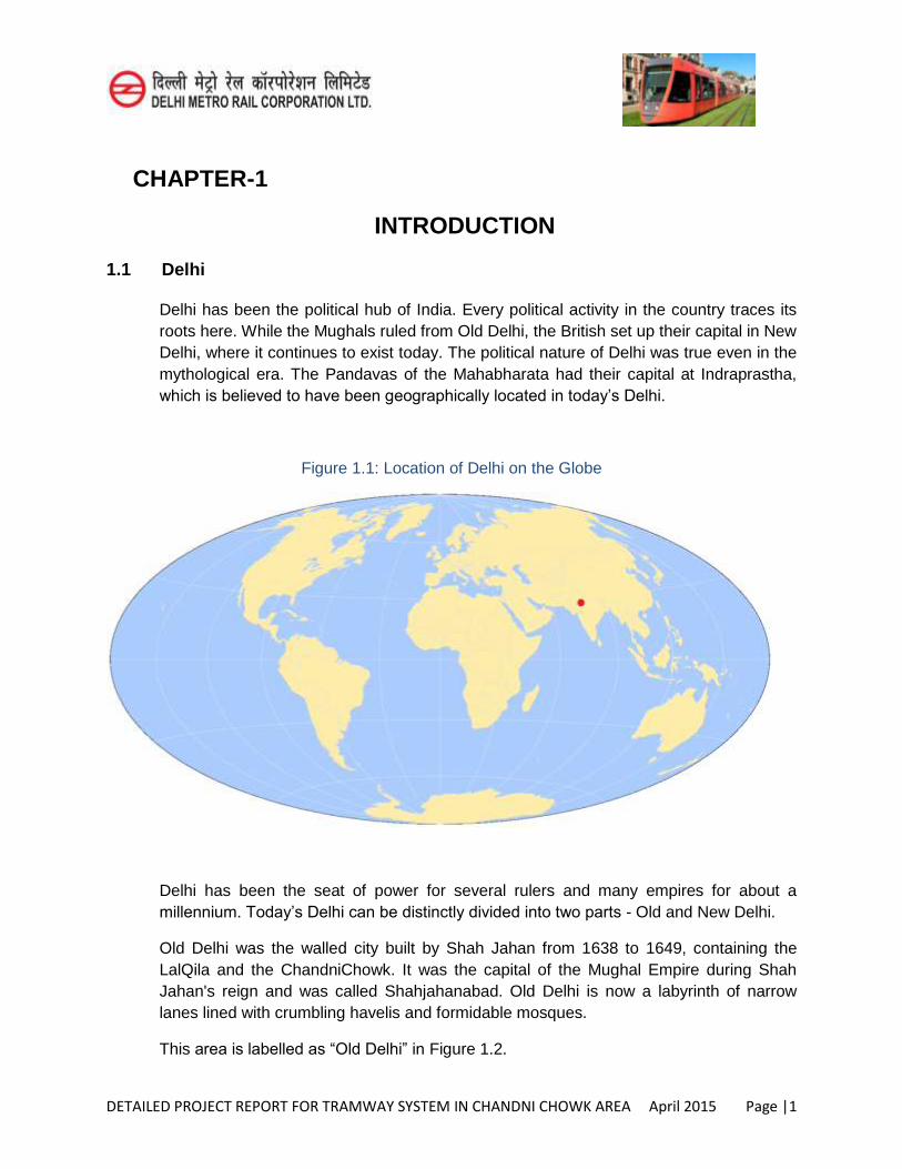
Delhi has been the political hub of India. Every political activity in the country traces its roots here. While the Mughals ruled from Old Delhi, the British set up their capital in New Delhi, where it continues to exist today. The political nature of Delhi was true even in the mythological era. The Pandavas of the Mahabharata had their capital at Indraprastha, which is believed to have been geographically located in today’s Delhi.
Figure 1.1: Location of Delhi on the Globe
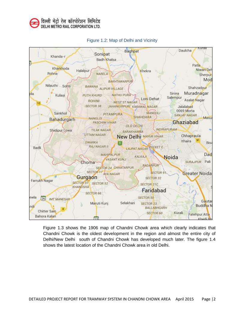
Delhi has been the seat of power for several rulers and many empires for about a millennium. Today’s Delhi can be distinctly divided into two parts - Old and New Delhi.
Old Delhi was the walled city built by Shah Jahan from 1638 to 1649, containing the LalQila and the ChandniChowk. It was the capital of the Mughal Empire during Shah Jahan's reign and was called Shahjahanabad. Old Delhi is now a labyrinth of narrow lanes lined with crumbling havelis and formidable mosques.
This area is labelled as “Old Delhi” in Figure 1.2.
DETAILED PROJECT REPORT FOR TRAMWAY SYSTEM IN CHANDNI CHOWK AREA April 2015 Page |2
Figure 1.2: Map of Delhi and Vicinity
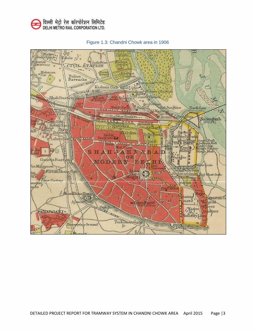
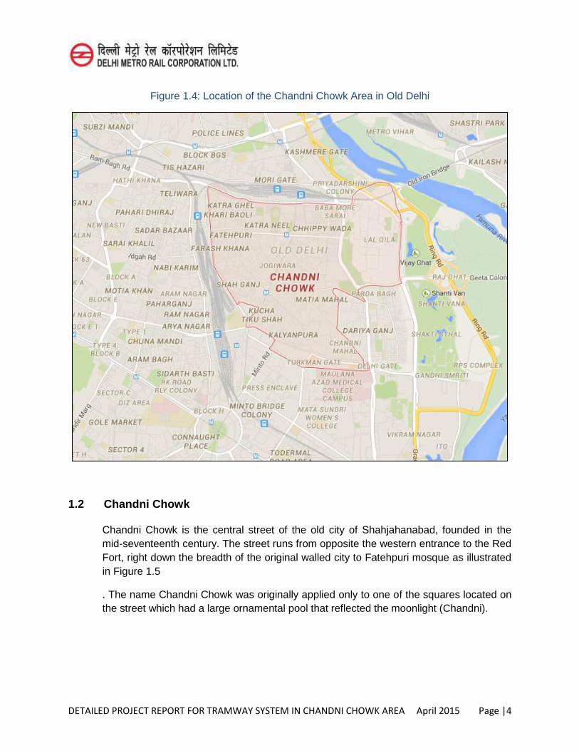
Figure 1.3 shows the 1906 map of Chandni Chowk area which clearly indicates that Chandni Chowk is the oldest development in the region and almost the entire city of Delhi/New Delhi south of Chandni Chowk has developed much later. The figure 1.4 shows the latest location of the Chandni Chowk area in old Delhi.
DETAILED PROJECT REPORT FOR TRAMWAY SYSTEM IN CHANDNI CHOWK AREA April 2015 Page |3
Figure 1.3: Chandni Chowk area in 1906
DETAILED PROJECT REPORT FOR TRAMWAY SYSTEM IN CHANDNI CHOWK AREA April 2015 Page |4
Figure 1.4: Location of the Chandni Chowk Area in Old Delhi
1.2 Chandni Chowk
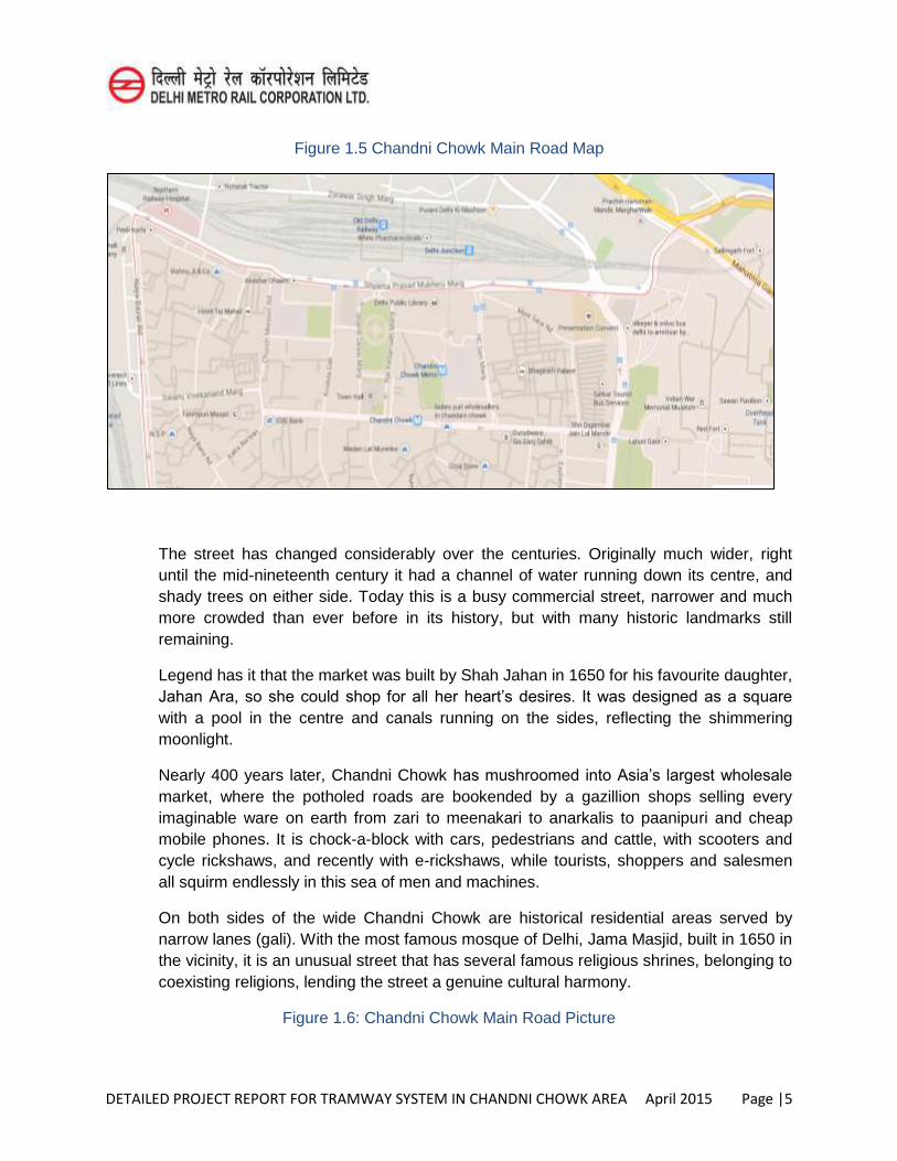
Chandni Chowk is the central street of the old city of Shahjahanabad, founded in the mid-seventeenth century. The street runs from opposite the western entrance to the Red Fort, right down the breadth of the original walled city to Fatehpuri mosque as illustrated in Figure 1.5
. The name Chandni Chowk was originally applied only to one of the squares located on the street which had a large ornamental pool that reflected the moonlight (Chandni).
DETAILED PROJECT REPORT FOR TRAMWAY SYSTEM IN CHANDNI CHOWK AREA April 2015 Page |5
Figure 1.5 Chandni Chowk Main Road Map
The street has changed considerably over the centuries. Originally much wider, right until the mid-nineteenth century it had a channel of water running down its centre, and shady trees on either side. Today this is a busy commercial street, narrower and much more crowded than ever before in its history, but with many historic landmarks still remaining.
Legend has it that the market was built by Shah Jahan in 1650 for his favourite daughter, Jahan Ara, so she could shop for all her heart’s desires. It was designed as a square
with a pool in the centre and canals running on the sides, reflecting the shimmering moonlight.
Nearly 400 years later, Chandni Chowk has mushroomed into Asia’s largest wholesale
market, where the potholed roads are bookended by a gazillion shops selling every imaginable ware on earth from zari to meenakari to anarkalis to paanipuri and cheap mobile phones. It is chock-a-block with cars, pedestrians and cattle, with scooters and cycle rickshaws, and recently with e-rickshaws, while tourists, shoppers and salesmen all squirm endlessly in this sea of men and machines.
On both sides of the wide Chandni Chowk are historical residential areas served by narrow lanes (gali). With the most famous mosque of Delhi, Jama Masjid, built in 1650 in the vicinity, it is an unusual street that has several famous religious shrines, belonging to coexisting religions, lending the street a genuine cultural harmony.
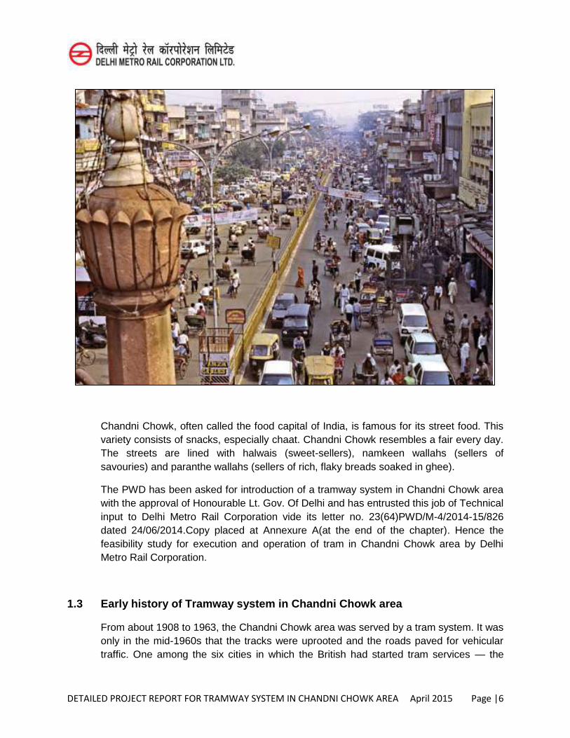
Figure 1.6: Chandni Chowk Main Road Picture
DETAILED PROJECT REPORT FOR TRAMWAY SYSTEM IN CHANDNI CHOWK AREA April 2015 Page |6
Chandni Chowk, often called the food capital of India, is famous for its street food. This variety consists of snacks, especially chaat. Chandni Chowk resembles a fair every day. The streets are lined with halwais (sweet-sellers), namkeen wallahs (sellers of savouries) and paranthe wallahs (sellers of rich, flaky breads soaked in ghee).
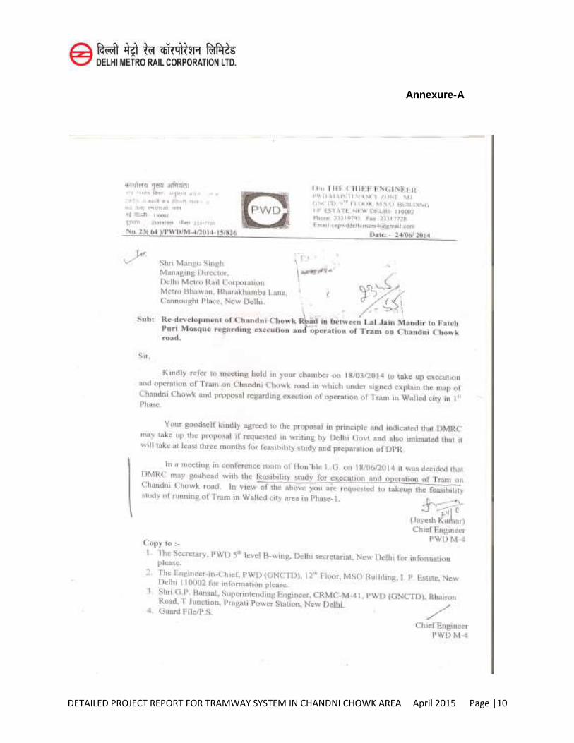
The PWD has been asked for introduction of a tramway system in Chandni Chowk area with the approval of Honourable Lt. Gov. Of Delhi and has entrusted this job of Technical input to Delhi Metro Rail Corporation vide its letter no. 23(64)PWD/M-4/2014-15/826 dated 24/06/2014.Copy placed at Annexure A(at the end of the chapter). Hence the feasibility study for execution and operation of tram in Chandni Chowk area by Delhi Metro Rail Corporation.
1.3 Early history of Tramway system in Chandni Chowk area
From about 1908 to 1963, the Chandni Chowk area was served by a tram system. It was only in the mid-1960s that the tracks were uprooted and the roads paved for vehicular traffic. One among the six cities in which the British had started tram services — the
DETAILED PROJECT REPORT FOR TRAMWAY SYSTEM IN CHANDNI CHOWK AREA April 2015 Page |7
others being Kanpur, Bombay, Calcutta, Patna and Madras — Delhi soon found the slow-moving tram an anachronism in a city where the population and automobiles were increasing at a galloping pace. Today, Kolkata remains the only city with trams for public transport.
The tram connected Ajmeri Gate, Paharganj, Sadar Bazaar and Sabzi Mandi with Chandni Chowk and Jama Masjid. At its peak, the tramway spanned about 22 kilometres, connecting Tees Hazari and Sabzi Mandi to Sadar Bazaar, Bara Hindu Rao and Paharganj via Chandni Chowk, Jama Masjid, Chawri Bazaar, LalKuan, Katra Badiyan and Fatehpuri.
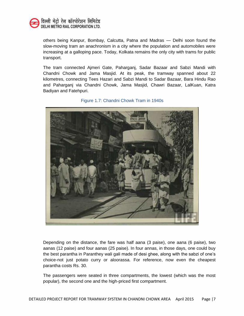
Figure 1.7: Chandni Chowk Tram in 1940s
Depending on the distance, the fare was half aana (3 paise), one aana (6 paise), two aanas (12 paise) and four aanas (25 paise). In four annas, in those days, one could buy the best parantha in Paranthey wali gali made of desi ghee, along with the sabzi of one’s
choice-not just potato curry or aloorassa. For reference, now even the cheapest parantha costs Rs. 30.
The passengers were seated in three compartments, the lowest (which was the most popular), the second one and the high-priced first compartment.
DETAILED PROJECT REPORT FOR TRAMWAY SYSTEM IN CHANDNI CHOWK AREA April 2015 Page |8
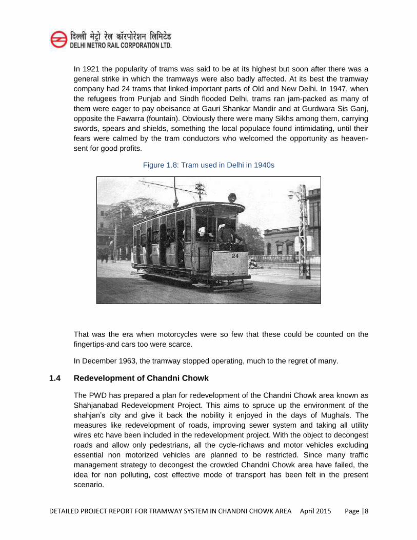
In 1921 the popularity of trams was said to be at its highest but soon after there was a general strike in which the tramways were also badly affected. At its best the tramway company had 24 trams that linked important parts of Old and New Delhi. In 1947, when the refugees from Punjab and Sindh flooded Delhi, trams ran jam-packed as many of them were eager to pay obeisance at Gauri Shankar Mandir and at Gurdwara Sis Ganj, opposite the Fawarra (fountain). Obviously there were many Sikhs among them, carrying swords, spears and shields, something the local populace found intimidating, until their fears were calmed by the tram conductors who welcomed the opportunity as heaven-sent for good profits.
Figure 1.8: Tram used in Delhi in 1940s
That was the era when motorcycles were so few that these could be counted on the fingertips-and cars too were scarce.
In December 1963, the tramway stopped operating, much to the regret of many.
1.4 Redevelopment of Chandni Chowk
The PWD has prepared a plan for redevelopment of the Chandni Chowk area known as Shahjanabad Redevelopment Project. This aims to spruce up the environment of the shahjan’s city and give it back the nobility it enjoyed in the days of Mughals. The measures like redevelopment of roads, improving sewer system and taking all utility wires etc have been included in the redevelopment project. With the object to decongest roads and allow only pedestrians, all the cycle-richaws and motor vehicles excluding essential non motorized vehicles are planned to be restricted. Since many traffic management strategy to decongest the crowded Chandni Chowk area have failed, the idea for non polluting, cost effective mode of transport has been felt in the present scenario.
DETAILED PROJECT REPORT FOR TRAMWAY SYSTEM IN CHANDNI CHOWK AREA April 2015 Page |9
1.5 PWD vide their letter no. 23(64)/PWD/M-4/2014-15/826 dated 24.06.2014 desired that DMRC should take up the study for the provision of Tramway System in Chandini Chowk area. Accordingly, DMRC has taken up this study, DMRC also engaged M/s Ayesha for getting the technical inputs from them. This report is now structured in the chapters as under:
Chapter 1 : Introduction
Chapter 2 : Traffic Demand Analysis
Chapter 3 : Need for Tram System
Chapter 4 : System Selection
Chapter 5 : Civil Engineering
Chapter 6 : Tram Operation Plan
Chapter 7 : Power Supply Arrangement
Chapter 8 : Maintenance Depot
Chapter 9 : Environment Impact Assessment and Management
Chapter 10 : Cost Estimate
Chapter 11 : Financing Options , Fair Structure & Financial Viability
Chapter 12 : Economic Appraisal
Chapter 13 : Disaster Management Measures
Chapter 14 : Disabled Friendly Features
Chapter 15 : Security Measures for a Tramway System
Chapter 16 : Multi Modal Traffic Integration for Tram
Chapter 17 : Conclusions and Recommendations
DETAILED PROJECT REPORT FOR TRAMWAY SYSTEM IN CHANDNI CHOWK AREA April 2015 Page |10
Annexure-A
DETAILED PROJECT REPORT FOR TRAMWAY SYSTEM IN CHANDNI CHOWK AREA April 2015 Page |1
CHAPTER-2
TRAFFIC DEMAND ANYASIS
2.1 Study Background
The traffic volume count surveys for a period of 16 hours (6 a.m. to 10 p.m.), parking surveys for a period of 16 hours (6 a.m. to 10 p.m.) and pedestrian count surveys for a period of 9 hours (11 a.m. to 8 p.m.) have been conducted on a typical working day.
2.2 Brief Description of Traffic Surveys
2.2.1 Traffic volume count survey
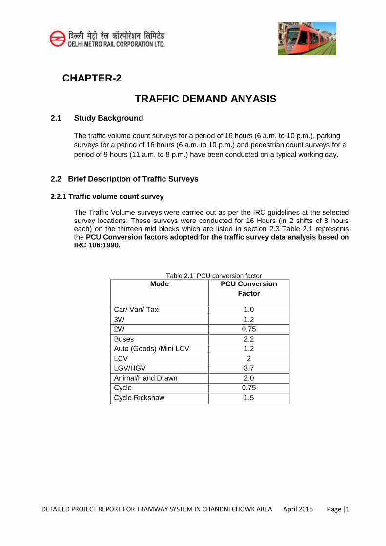
The Traffic Volume surveys were carried out as per the IRC guidelines at the selected survey locations. These surveys were conducted for 16 Hours (in 2 shifts of 8 hours each) on the thirteen mid blocks which are listed in section 2.3 Table 2.1 represents the PCU Conversion factors adopted for the traffic survey data analysis based on IRC 106:1990.
Table 2.1: PCU conversion factor
Mode PCU Conversion Factor
Car/ Van/ Taxi 1.0 3W 1.2 2W 0.75 Buses 2.2 Auto (Goods) /Mini LCV 1.2 LCV 2 LGV/HGV 3.7 Animal/Hand Drawn 2.0 Cycle 0.75 Cycle Rickshaw 1.5
DETAILED PROJECT REPORT FOR TRAMWAY SYSTEM IN CHANDNI CHOWK AREA April 2015 Page |2
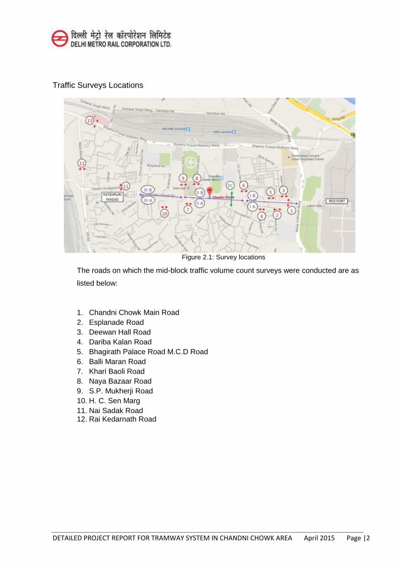
Traffic Surveys Locations
Figure 2.1: Survey locations
The roads on which the mid-block traffic volume count surveys were conducted are as
listed below:
1. Chandni Chowk Main Road 2. Esplanade Road 3. Deewan Hall Road 4. Dariba Kalan Road 5. Bhagirath Palace Road M.C.D Road 6. Balli Maran Road 7. Khari Baoli Road 8. Naya Bazaar Road 9. S.P. Mukherji Road 10. H. C. Sen Marg 11. Nai Sadak Road 12. Rai Kedarnath Road
DETAILED PROJECT REPORT FOR TRAMWAY SYSTEM IN CHANDNI CHOWK AREA April 2015 Page |3
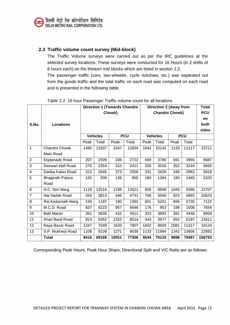
2.3 Traffic volume count survey (Mid-block)
The Traffic Volume surveys were carried out as per the IRC guidelines at the
selected survey locations. These surveys were conducted for 16 Hours (in 2 shifts of
8 hours each) on the thirteen mid blocks which are listed in section 2.2.
The passenger traffic (cars, two-wheeler, cycle rickshaw, etc.) was separated out
from the goods traffic and the total traffic on each road was computed on each road
and is presented in the following table.
Table 2.2: 16 hour Passenger Traffic volume count for all locations
S.No. Locations
Direction 1 (Towards Chandni
Chowk)
Direction 2 (Away from
Chandni Chowk)
Total
PCU
on
both
sides
Vehicles PCU Vehicles PCU
Peak Total Peak Total Peak Total Peak Total
1 Chandni Chowk
Main Road
1490 11637 1547 12604 1042 10142 1133 11117 23721
2 Esplanade Road 207 2509 236 2722 689 3790 691 3965 6687
3 Deewan Hall Road 275 2354 310 2411 330 3016 352 3244 5655
4 Dariba Kalan Road 312 2645 373 2956 331 2626 346 2962 5918
5 Bhagirath Palace
Road
155 939 136 855 180 1394 190 1465 2320
6 H.C. Sen Marg 1119 12516 1198 13421 926 8508 1043 9286 22707
7 Nai Sadak Road 343 3813 446 4731 768 5040 823 5892 10623
8 Rai Kedarnath Marg 159 1187 190 1392 601 5201 666 5730 7122
9 M.C.D. Road 837 6223 957 6646 176 953 198 1008 7654
10 Balli Maran 351 3835 432 4511 323 3893 381 4448 8959
11 Khari Baoli Road 813 6352 1322 8214 443 3977 652 5197 13411
12 Naya Bazar Road 1247 7049 1633 7807 1602 9609 2081 11317 19124
13 S.P. Mukherji Road 1108 8109 1271 9036 1133 11984 1342 13856 22892
Total 8416 69168 10051 77306 8544 70133 9898 79487 156793
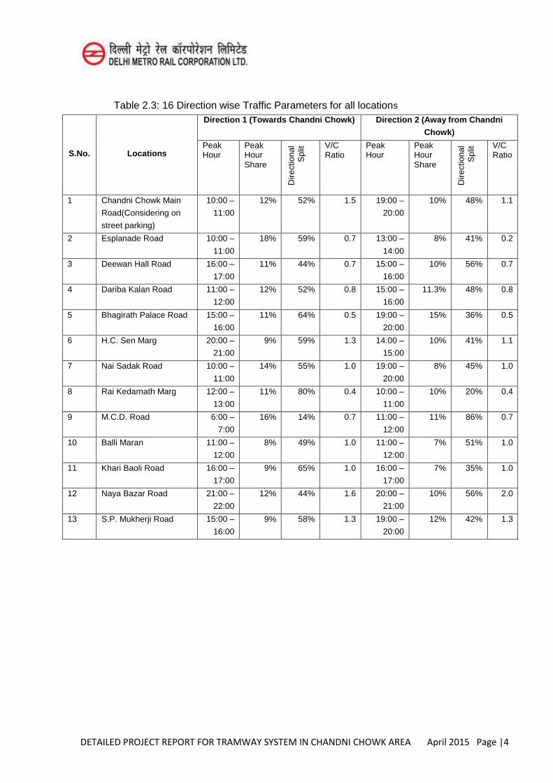
Corresponding Peak Hours, Peak Hour Share, Directional Split and V/C Ratio are as follows:
DETAILED PROJECT REPORT FOR TRAMWAY SYSTEM IN CHANDNI CHOWK AREA April 2015 Page |4
Table 2.3: 16 Direction wise Traffic Parameters for all locations
S.No. Locations
Direction 1 (Towards Chandni Chowk) Direction 2 (Away from Chandni
Chowk)
Peak Hour
Peak Hour Share
Dire
ctio
nal
Spl
it V/C
Ratio Peak Hour
Peak Hour Share
Dire
ctio
nal
Spl
it V/C
Ratio
1 Chandni Chowk Main
Road(Considering on
street parking)
10:00 –
11:00
12% 52% 1.5 19:00 –
20:00
10% 48% 1.1
2 Esplanade Road 10:00 –
11:00
18% 59% 0.7 13:00 –
14:00
8% 41% 0.2
3 Deewan Hall Road 16:00 –
17:00
11% 44% 0.7 15:00 –
16:00
10% 56% 0.7
4 Dariba Kalan Road 11:00 –
12:00
12% 52% 0.8 15:00 –
16:00
11.3% 48% 0.8
5 Bhagirath Palace Road 15:00 –
16:00
11% 64% 0.5 19:00 –
20:00
15% 36% 0.5
6 H.C. Sen Marg 20:00 –
21:00
9% 59% 1.3 14:00 –
15:00
10% 41% 1.1
7 Nai Sadak Road 10:00 –
11:00
14% 55% 1.0 19:00 –
20:00
8% 45% 1.0
8 Rai Kedarnath Marg 12:00 –
13:00
11% 80% 0.4 10:00 –
11:00
10% 20% 0.4
9 M.C.D. Road 6:00 –
7:00
16% 14% 0.7 11:00 –
12:00
11% 86% 0.7
10 Balli Maran 11:00 –
12:00
8% 49% 1.0 11:00 –
12:00
7% 51% 1.0
11 Khari Baoli Road 16:00 –
17:00
9% 65% 1.0 16:00 –
17:00
7% 35% 1.0
12 Naya Bazar Road 21:00 –
22:00
12% 44% 1.6 20:00 –
21:00
10% 56% 2.0
13 S.P. Mukherji Road 15:00 –
16:00
9% 58% 1.3 19:00 –
20:00
12% 42% 1.3
DETAILED PROJECT REPORT FOR TRAMWAY SYSTEM IN CHANDNI CHOWK AREA April 2015 Page |5
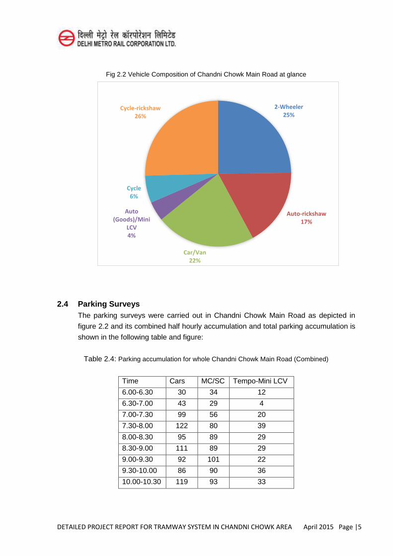
Fig 2.2 Vehicle Composition of Chandni Chowk Main Road at glance
2.4 Parking Surveys The parking surveys were carried out in Chandni Chowk Main Road as depicted in
figure 2.2 and its combined half hourly accumulation and total parking accumulation is
shown in the following table and figure:
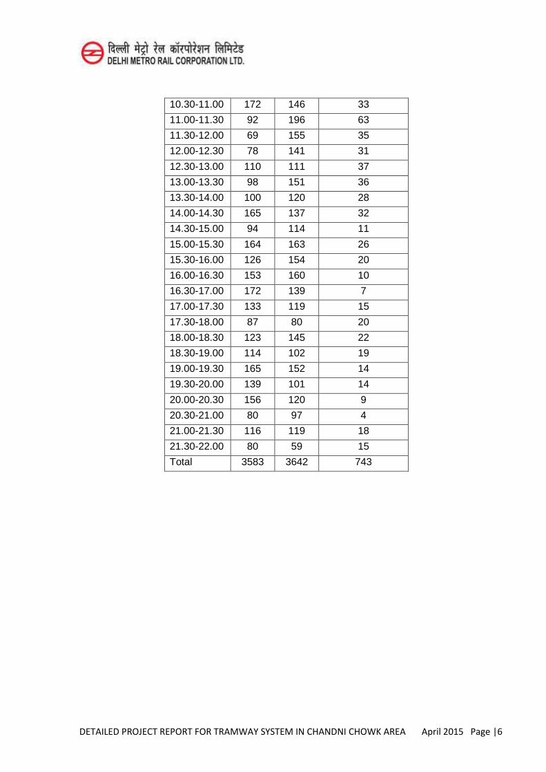
Table 2.4: Parking accumulation for whole Chandni Chowk Main Road (Combined)
Time Cars MC/SC Tempo-Mini LCV
6.00-6.30 30 34 12
6.30-7.00 43 29 4
7.00-7.30 99 56 20
7.30-8.00 122 80 39
8.00-8.30 95 89 29
8.30-9.00 111 89 29
9.00-9.30 92 101 22
9.30-10.00 86 90 36
10.00-10.30 119 93 33
2-Wheeler 25%
Auto-rickshaw 17%
Car/Van 22%
Auto (Goods)/Mini
LCV 4%
Cycle 6%
Cycle-rickshaw 26%
DETAILED PROJECT REPORT FOR TRAMWAY SYSTEM IN CHANDNI CHOWK AREA April 2015 Page |6
10.30-11.00 172 146 33
11.00-11.30 92 196 63
11.30-12.00 69 155 35
12.00-12.30 78 141 31
12.30-13.00 110 111 37
13.00-13.30 98 151 36
13.30-14.00 100 120 28
14.00-14.30 165 137 32
14.30-15.00 94 114 11
15.00-15.30 164 163 26
15.30-16.00 126 154 20
16.00-16.30 153 160 10
16.30-17.00 172 139 7
17.00-17.30 133 119 15
17.30-18.00 87 80 20
18.00-18.30 123 145 22
18.30-19.00 114 102 19
19.00-19.30 165 152 14
19.30-20.00 139 101 14
20.00-20.30 156 120 9
20.30-21.00 80 97 4
21.00-21.30 116 119 18
21.30-22.00 80 59 15
Total 3583 3642 743
DETAILED PROJECT REPORT FOR TRAMWAY SYSTEM IN CHANDNI CHOWK AREA April 2015 Page |7
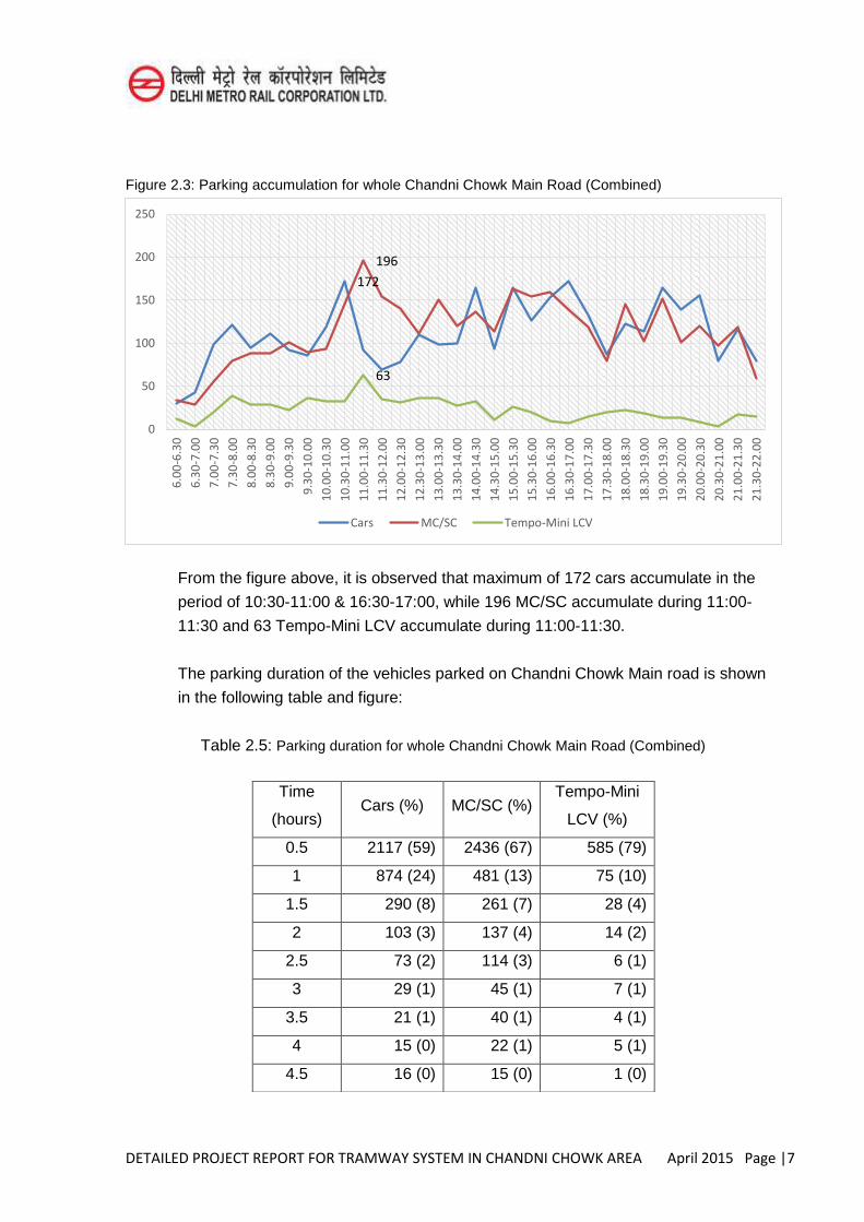
Figure 2.3: Parking accumulation for whole Chandni Chowk Main Road (Combined)
From the figure above, it is observed that maximum of 172 cars accumulate in the
period of 10:30-11:00 & 16:30-17:00, while 196 MC/SC accumulate during 11:00-
11:30 and 63 Tempo-Mini LCV accumulate during 11:00-11:30.
The parking duration of the vehicles parked on Chandni Chowk Main road is shown
in the following table and figure:
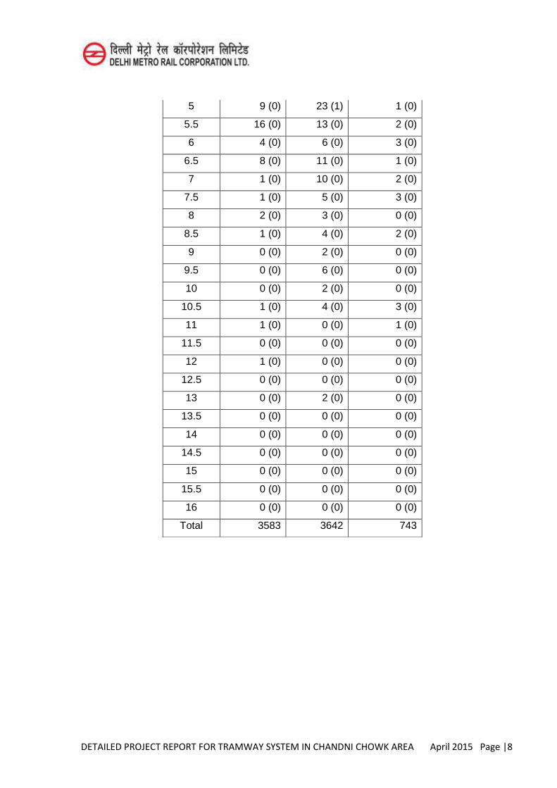
Table 2.5: Parking duration for whole Chandni Chowk Main Road (Combined)
172
196
63
0
50
100
150
200
250
6.0
0-6
.30
6.3
0-7
.00
7.0
0-7
.30
7.3
0-8
.00
8.0
0-8
.30
8.3
0-9
.00
9.0
0-9
.30
9.3
0-1
0.0
0
10
.00
-10
.30
10
.30
-11
.00
11
.00
-11
.30
11
.30
-12
.00
12
.00
-12
.30
12
.30
-13
.00
13
.00
-13
.30
13
.30
-14
.00
14
.00
-14
.30
14
.30
-15
.00
15
.00
-15
.30
15
.30
-16
.00
16
.00
-16
.30
16
.30
-17
.00
17
.00
-17
.30
17
.30
-18
.00
18
.00
-18
.30
18
.30
-19
.00
19
.00
-19
.30
19
.30
-20
.00
20
.00
-20
.30
20
.30
-21
.00
21
.00
-21
.30
21
.30
-22
.00
Cars MC/SC Tempo-Mini LCV
Time
(hours) Cars (%) MC/SC (%)
Tempo-Mini
LCV (%)
0.5 2117 (59) 2436 (67) 585 (79)
1 874 (24) 481 (13) 75 (10)
1.5 290 (8) 261 (7) 28 (4)
2 103 (3) 137 (4) 14 (2)
2.5 73 (2) 114 (3) 6 (1)
3 29 (1) 45 (1) 7 (1)
3.5 21 (1) 40 (1) 4 (1)
4 15 (0) 22 (1) 5 (1)
4.5 16 (0) 15 (0) 1 (0)
DETAILED PROJECT REPORT FOR TRAMWAY SYSTEM IN CHANDNI CHOWK AREA April 2015 Page |8
5 9 (0) 23 (1) 1 (0)
5.5 16 (0) 13 (0) 2 (0)
6 4 (0) 6 (0) 3 (0)
6.5 8 (0) 11 (0) 1 (0)
7 1 (0) 10 (0) 2 (0)
7.5 1 (0) 5 (0) 3 (0)
8 2 (0) 3 (0) 0 (0)
8.5 1 (0) 4 (0) 2 (0)
9 0 (0) 2 (0) 0 (0)
9.5 0 (0) 6 (0) 0 (0)
10 0 (0) 2 (0) 0 (0)
10.5 1 (0) 4 (0) 3 (0)
11 1 (0) 0 (0) 1 (0)
11.5 0 (0) 0 (0) 0 (0)
12 1 (0) 0 (0) 0 (0)
12.5 0 (0) 0 (0) 0 (0)
13 0 (0) 2 (0) 0 (0)
13.5 0 (0) 0 (0) 0 (0)
14 0 (0) 0 (0) 0 (0)
14.5 0 (0) 0 (0) 0 (0)
15 0 (0) 0 (0) 0 (0)
15.5 0 (0) 0 (0) 0 (0)
16 0 (0) 0 (0) 0 (0)
Total 3583 3642 743
DETAILED PROJECT REPORT FOR TRAMWAY SYSTEM IN CHANDNI CHOWK AREA April 2015 Page |9
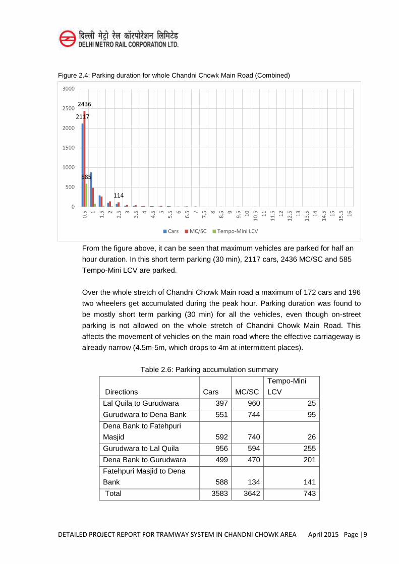
Figure 2.4: Parking duration for whole Chandni Chowk Main Road (Combined)
From the figure above, it can be seen that maximum vehicles are parked for half an
hour duration. In this short term parking (30 min), 2117 cars, 2436 MC/SC and 585
Tempo-Mini LCV are parked.
Over the whole stretch of Chandni Chowk Main road a maximum of 172 cars and 196
two wheelers get accumulated during the peak hour. Parking duration was found to
be mostly short term parking (30 min) for all the vehicles, even though on-street
parking is not allowed on the whole stretch of Chandni Chowk Main Road. This
affects the movement of vehicles on the main road where the effective carriageway is
already narrow (4.5m-5m, which drops to 4m at intermittent places).
Table 2.6: Parking accumulation summary
Directions Cars MC/SC
Tempo-Mini
LCV
Lal Quila to Gurudwara 397 960 25
Gurudwara to Dena Bank 551 744 95
Dena Bank to Fatehpuri
Masjid 592 740 26
Gurudwara to Lal Quila 956 594 255
Dena Bank to Gurudwara 499 470 201
Fatehpuri Masjid to Dena
Bank 588 134 141
Total 3583 3642 743
2117
2436
114
585
0
500
1000
1500
2000
2500
3000 0
.5
1
1.5
2
2.5
3
3.5
4
4.5
5
5.5
6
6.5
7
7.5
8
8.5
9
9.5
10
10
.5
11
11
.5
12
12
.5
13
13
.5
14
14
.5
15
15
.5
16
Cars MC/SC Tempo-Mini LCV
DETAILED PROJECT REPORT FOR TRAMWAY SYSTEM IN CHANDNI CHOWK AREA April 2015 Page |10
From table 2.6, it is calculated that the Total Cars and Two wheelers that were
parked on Chandni Chowk main road were 3583 and 3642 respectively.
2.5 Pedestrian Count Surveys The pedestrian count survey (PC) was done on the Chandni Chowk Main Road, in front
of Bank of India ATM, for both the directions on both sides of the road for the period of
11:00 am to 8:00 pm. Table 2.7: Direction wise pedestrian count
Location Direction Total Pedestrian
Count
Gurudwara Fatehpuri Masjid To
Gurudwara
7822
Gurudwara To Fatehpuri
Masjid
8676
Opp.
Gurudwara
Fatehpuri Masjid To
Gurudwara
7832
Gurudwara To Fatehpuri
Masjid
7873
Table 2.8: Direction wise peak hour characteristics of pedestrian count
Location Direction Peak
Hour
Peak Hour
Pedestria
ns
Peak
Hour
Share
Directio
n Split
Gurudwara Fatehpuri Masjid
To Gurudwara
18:00-
19:00
1080 14% 49.3
Gurudwara To
Fatehpuri Masjid
19:00-
20:00
1110 13% 50.7
Opp.
Gurudwara
Fatehpuri Masjid
To Gurudwara
17:00-
18:00
1020 13% 49.3
Gurudwara To
Fatehpuri Masjid
12:00-
13:00
1050 13% 50.7
The total pedestrian count (for both the sides together) is observed to be 32,203. It is
assumed that 30% of these would contribute to the estimated ridership of tram i.e.
9661 pedestrians may shift to tram.
DETAILED PROJECT REPORT FOR TRAMWAY SYSTEM IN CHANDNI CHOWK AREA April 2015 Page |11
2.6 Observation from Traffic Surveys 2.6.1 Traffic Volume Count (TVC)
Due to high on-street parking on main roads such as Chandni Chowk Main Road,
H.C.Sen Marg and Shyama Prasad Mukherji Marg, though the carriageway ranges
from 6 lanes (3+3) to 4-lanes, actual width available for moving traffic gets reduced to
one lane for most of the time. As a result, traffic jams with very low speeds are
observed. The peak hour traffic observed per direction is of the range 1000-1500 pcu
which is very low for such wide roads.
Apart from the above roads Rai Kedarnath road and M.C.D. road (Shanti Desai
Road), though one way, were the only roads where the share of motorable traffic
especially cars was found to be significant.
The composition of traffic on rest of the roads viz. Esplanade road, Deewan Hall
road, Dariba Kalan road, Bhagirath Palace road, Nai Sadak, Balli Maran Road, Khari
Baoli road and Naya Bazar road consisted mainly of Cycle Rickshaws, Two
wheelers, Cycles or Mini LCVs (small Tempos). At Khari Baoli Road considerable
amount of Hand Carts were also observed.
2.6.3 Parking:
Over the whole stretch of Chandni Chowk Main road a maximum of 172 cars and 196
two wheelers get accumulated during the peak hour. Parking duration was found to
be mostly short term parking (30 min) for all the vehicles, even though on-street
parking is not allowed on the whole stretch of Chandni Chowk Main Road. This
affects the movement of vehicles on the main road where the effective carriageway is
already narrow (7m, which drops to 4- 4.5m at intermittent places due to on street
parking). Hence, there is a need to provide the parking area for the vehicles
accumulated maximum at any point of time which is 172 cars and 196 two wheelers.
Taking E.C.S. of MC/SC as 0.25 (UDPFI 2013), the total parking requirement for cars
and MC/SC is calculated. The total parking required for cars and MC/SC together is
calculated as 221 E.C.S. [172 + (196*0.25)].
2.6.4 Pedestrian:
On most of the locations/ directions ( 3 out of 4)pedestrian peak hour was found to be
during evening 5pm to 8 pm. Peak hour pedestrian count is observed to be around
1000-1100 in all four locations/ directions. The directional split is also same on both
the direction (50:50). The total pedestrian count (for both the sides together) is
observed to be 32,203 near gurudwara (both directions put together)
DETAILED PROJECT REPORT FOR TRAMWAY SYSTEM IN CHANDNI CHOWK AREA April 2015 Page |12
2.7 Objective of the Transportation
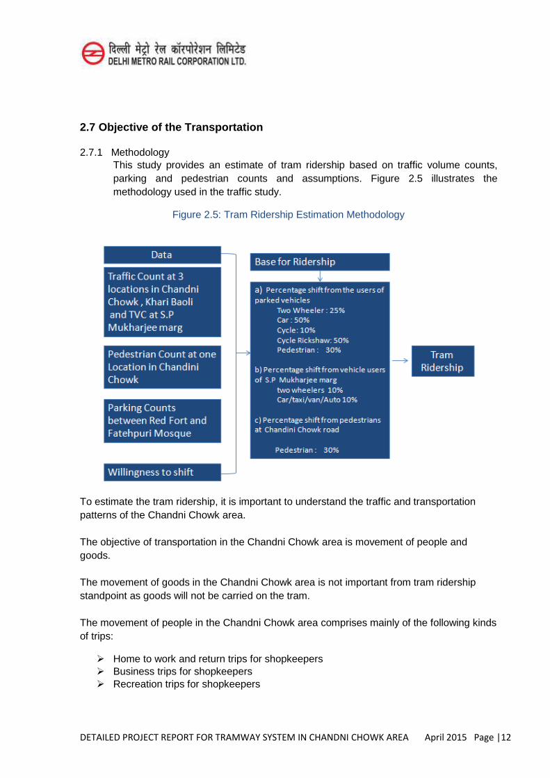
2.7.1 Methodology This study provides an estimate of tram ridership based on traffic volume counts, parking and pedestrian counts and assumptions. Figure 2.5 illustrates the methodology used in the traffic study.
Figure 2.5: Tram Ridership Estimation Methodology
To estimate the tram ridership, it is important to understand the traffic and transportation patterns of the Chandni Chowk area. The objective of transportation in the Chandni Chowk area is movement of people and goods. The movement of goods in the Chandni Chowk area is not important from tram ridership standpoint as goods will not be carried on the tram. The movement of people in the Chandni Chowk area comprises mainly of the following kinds of trips:
Home to work and return trips for shopkeepers Business trips for shopkeepers Recreation trips for shopkeepers
DETAILED PROJECT REPORT FOR TRAMWAY SYSTEM IN CHANDNI CHOWK AREA April 2015 Page |13
Business trips for shoppers Recreation trips for shoppers
The modes of transport used by people in the Chandni Chowk area are as follows:
Walk Cycle Cycle Rickshaw Auto Rickshaw Two-wheelers Four-wheelers Metro + Walk Metro + Rickshaw
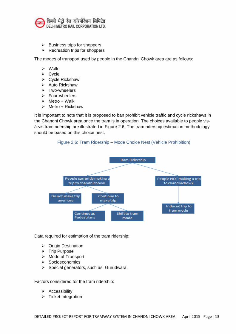
It is important to note that it is proposed to ban prohibit vehicle traffic and cycle rickshaws in the Chandni Chowk area once the tram is in operation. The choices available to people vis-à-vis tram ridership are illustrated in Figure 2.6. The tram ridership estimation methodology should be based on this choice nest.
Figure 2.6: Tram Ridership – Mode Choice Nest (Vehicle Prohibition)
Data required for estimation of the tram ridership:
Origin Destination Trip Purpose Mode of Transport Socioeconomics Special generators, such as, Gurudwara.
Factors considered for the tram ridership:
Accessibility Ticket Integration
DETAILED PROJECT REPORT FOR TRAMWAY SYSTEM IN CHANDNI CHOWK AREA April 2015 Page |14
Fares Speed Stop Distance Network Density Reliability
2.8 Estimation of Ridership of tram
The network of tramway proposed in the Chandni Chowk area is a closed loop covering Chandni Chowk Road, Netaji Subhash Place Marg, S.P. Mukherji Marg, Naya Bazar Marg and Khari Baoli Marg. The length of this closed loop is 4.5 Kms. It is proposed to provide 10 number of stations distance varying from 240 meter to 830 meter. Out of these 10 stations, 3 are proposed to be provided on elevated alignment and balance 7 are proposed at grade.
The determination of ridership on this loop cannot be done by normal method of modeling and assignment being a small area and population of entire city, trips not contributing to the traffic projections. The traffic on this tramway network will mainly be effected by the work trips and public coming to Chandni Chowk area for purchasing the various items and also for fun. The small number of trips will also be contributed by the traffic on S.P. Mukherji Marg, Red Fort metro station under construction, Khari Baoli Road and Naya Bazaar Marg. DMRC is also of the opinion that one of the station proposed to be located on this tramway network on Naya Bazaar Marg be finally connected to the metro across railway lines and on the side of Sadar Bazaar Marg (Proposed metro line between RK Ashram – Pulbangash – Azadpur – Janakpuri (West) in Phase-IV.
To have the approximate figure of ridership on the tramway network, the traffic volume count at 13 locations serving the Chandni Chowk area were conducted.
Pedestrian count on Chandni Chowk Road on one of the location was also carried out. Passenger’s interviews to know the likely shift from the present mode of transport to tramway network were also done. The on street parking for 16 hours of a day with hourly details on Chandni Chowk was also done. The intention to have survey of street parking was to find out that how many people are normally coming to Chandni Chowk road either for employment or for business.
Assessment of Ridership: Assessment of ridership for tramway network has been done taking into account the component of under-mentioned users of Chandni Chowk area:
1. Number of on street parking; 2. Pedestrian in Chandni Chowk area; 3. User of cycle & cycle rickshaw on Chandni Chowk Road; 4. User of S.P. Mukherji Marg;(2Wheelers,Cars/Taxies, Autos)Distinct number of
cars and two wheelers parked on Chandni Chowk road was also determined. The occupancy of car and two wheeler was taken 2 and 1 respectively. Number of distinct cars parked on Chandni Chowk road was enumerated as 3583
DETAILED PROJECT REPORT FOR TRAMWAY SYSTEM IN CHANDNI CHOWK AREA April 2015 Page |15
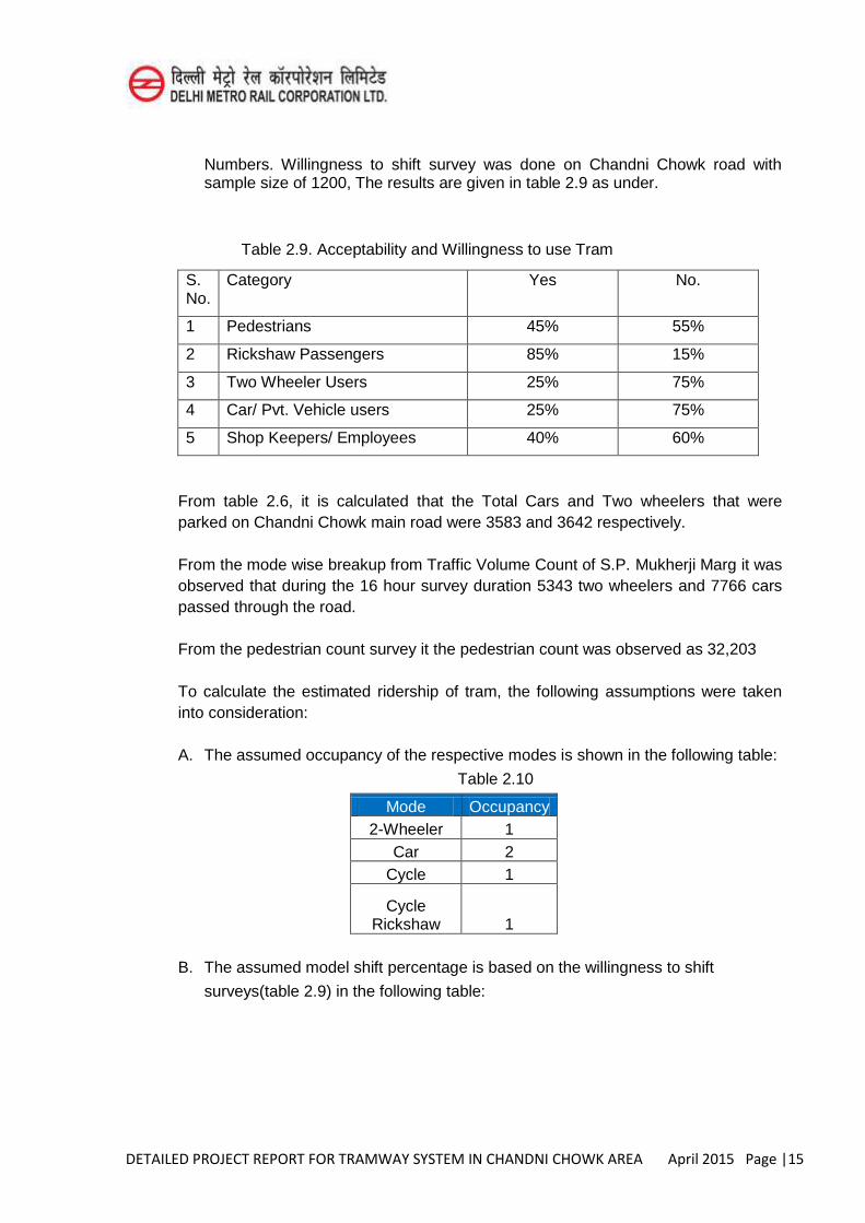
Numbers. Willingness to shift survey was done on Chandni Chowk road with sample size of 1200, The results are given in table 2.9 as under.
Table 2.9. Acceptability and Willingness to use Tram
S. No.
Category Yes No.
1 Pedestrians 45% 55%
2 Rickshaw Passengers 85% 15%
3 Two Wheeler Users 25% 75%
4 Car/ Pvt. Vehicle users 25% 75%
5 Shop Keepers/ Employees 40% 60%
From table 2.6, it is calculated that the Total Cars and Two wheelers that were parked on Chandni Chowk main road were 3583 and 3642 respectively. From the mode wise breakup from Traffic Volume Count of S.P. Mukherji Marg it was observed that during the 16 hour survey duration 5343 two wheelers and 7766 cars passed through the road. From the pedestrian count survey it the pedestrian count was observed as 32,203 To calculate the estimated ridership of tram, the following assumptions were taken into consideration: A. The assumed occupancy of the respective modes is shown in the following table:
Table 2.10
Mode Occupancy 2-Wheeler 1
Car 2 Cycle 1
Cycle Rickshaw 1
B. The assumed model shift percentage is based on the willingness to shift
surveys(table 2.9) in the following table:
DETAILED PROJECT REPORT FOR TRAMWAY SYSTEM IN CHANDNI CHOWK AREA April 2015 Page |16
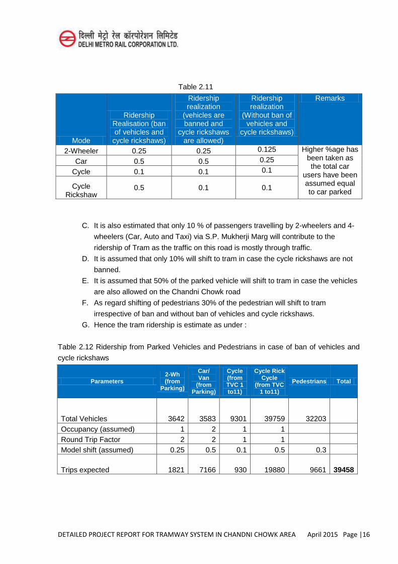
Table 2.11
Mode
Ridership Realisation (ban of vehicles and
cycle rickshaws)
Ridership realization
(vehicles are banned and
cycle rickshaws are allowed)
Ridership realization
(Without ban of vehicles and
cycle rickshaws)
Remarks
2-Wheeler 0.25 0.25 0.125 Higher %age has been taken as the total car
users have been assumed equal to car parked
Car 0.5 0.5 0.25
Cycle 0.1 0.1 0.1
Cycle Rickshaw
0.5 0.1 0.1
C. It is also estimated that only 10 % of passengers travelling by 2-wheelers and 4-
wheelers (Car, Auto and Taxi) via S.P. Mukherji Marg will contribute to the
ridership of Tram as the traffic on this road is mostly through traffic.
D. It is assumed that only 10% will shift to tram in case the cycle rickshaws are not
banned.
E. It is assumed that 50% of the parked vehicle will shift to tram in case the vehicles
are also allowed on the Chandni Chowk road
F. As regard shifting of pedestrians 30% of the pedestrian will shift to tram
irrespective of ban and without ban of vehicles and cycle rickshaws.
G. Hence the tram ridership is estimate as under :
Table 2.12 Ridership from Parked Vehicles and Pedestrians in case of ban of vehicles and
cycle rickshaws
Parameters 2-Wh (from
Parking)
Car/ Van
(from Parking)
Cycle (from TVC 1 to11)
Cycle Rick Cycle
(from TVC 1 to11)
Pedestrians Total
Total Vehicles 3642 3583 9301 39759 32203 Occupancy (assumed) 1 2 1 1 Round Trip Factor 2 2 1 1 Model shift (assumed) 0.25 0.5 0.1 0.5 0.3
Trips expected 1821 7166 930 19880 9661 39458
DETAILED PROJECT REPORT FOR TRAMWAY SYSTEM IN CHANDNI CHOWK AREA April 2015 Page |17
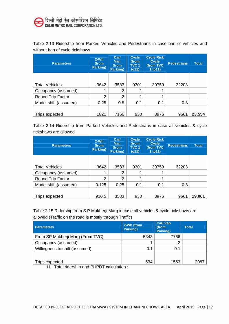
Table 2.13 Ridership from Parked Vehicles and Pedestrians in case ban of vehicles and
without ban of cycle rickshaws
Parameters 2-Wh (from
Parking)
Car/ Van
(from Parking)
Cycle (from TVC 1 to11)
Cycle Rick Cycle
(from TVC 1 to11)
Pedestrians Total
Total Vehicles 3642 3583 9301 39759 32203 Occupancy (assumed) 1 2 1 1 Round Trip Factor 2 2 1 1 Model shift (assumed) 0.25 0.5 0.1 0.1 0.3
Trips expected 1821 7166 930 3976 9661 23,554
Table 2.14 Ridership from Parked Vehicles and Pedestrians in case all vehicles & cycle
rickshaws are allowed
Parameters 2-Wh (from
Parking)
Car/ Van
(from Parking)
Cycle (from TVC 1 to11)
Cycle Rick Cycle
(from TVC 1 to11)
Pedestrians Total
Total Vehicles 3642 3583 9301 39759 32203 Occupancy (assumed) 1 2 1 1 Round Trip Factor 2 2 1 1 Model shift (assumed) 0.125 0.25 0.1 0.1 0.3
Trips expected 910.5 3583 930 3976 9661 19,061
Table 2.15 Ridership from S.P.Mukherji Marg in case all vehicles & cycle rickshaws are
allowed (Traffic on the road is mostly through Traffic)
Parameters 2-Wh (from Parking)
Car/ Van (from Parking)
Total
From SP Mukherji Marg (From TVC) 5343 7766 Occupancy (assumed) 1 2 Willingness to shift (assumed) 0.1 0.1
Trips expected 534 1553 2087 H. Total ridership and PHPDT calculation :
DETAILED PROJECT REPORT FOR TRAMWAY SYSTEM IN CHANDNI CHOWK AREA April 2015 Page |18
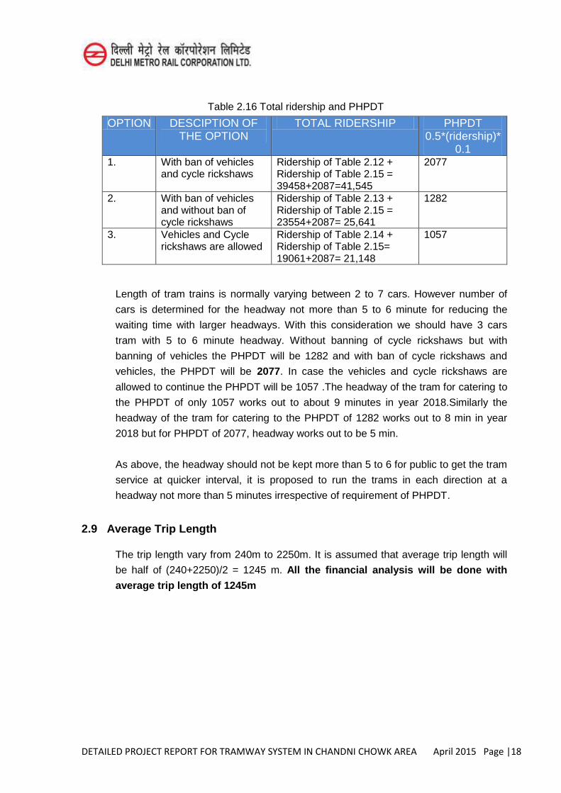
Table 2.16 Total ridership and PHPDT
OPTION DESCIPTION OF THE OPTION
TOTAL RIDERSHIP PHPDT 0.5*(ridership)*
0.1 1. With ban of vehicles
and cycle rickshaws Ridership of Table 2.12 + Ridership of Table 2.15 = 39458+2087=41,545
2077
2. With ban of vehicles and without ban of cycle rickshaws
Ridership of Table 2.13 + Ridership of Table 2.15 = 23554+2087= 25,641
1282
3. Vehicles and Cycle rickshaws are allowed
Ridership of Table 2.14 + Ridership of Table 2.15= 19061+2087= 21,148
1057
Length of tram trains is normally varying between 2 to 7 cars. However number of
cars is determined for the headway not more than 5 to 6 minute for reducing the
waiting time with larger headways. With this consideration we should have 3 cars
tram with 5 to 6 minute headway. Without banning of cycle rickshaws but with
banning of vehicles the PHPDT will be 1282 and with ban of cycle rickshaws and
vehicles, the PHPDT will be 2077. In case the vehicles and cycle rickshaws are
allowed to continue the PHPDT will be 1057 .The headway of the tram for catering to
the PHPDT of only 1057 works out to about 9 minutes in year 2018.Similarly the
headway of the tram for catering to the PHPDT of 1282 works out to 8 min in year
2018 but for PHPDT of 2077, headway works out to be 5 min.
As above, the headway should not be kept more than 5 to 6 for public to get the tram
service at quicker interval, it is proposed to run the trams in each direction at a
headway not more than 5 minutes irrespective of requirement of PHPDT.
2.9 Average Trip Length
The trip length vary from 240m to 2250m. It is assumed that average trip length will
be half of (240+2250)/2 = 1245 m. All the financial analysis will be done with
average trip length of 1245m
DETAILED PROJECT REPORT FOR TRAMWAY SYSTEM IN CHANDNI CHOWK AREA April 2015 Page |1
CHAPTER-3
NEED FOR A TRAM
3.1 Tramways Background
A tram (or tramcar, streetcar, trolley, trolley car or light rail) is a vehicle that runs on rail tracks along public urban streets and also sometimes on separate rights of way. The lines or networks operated by tramcars are called tramways. Trams are lighter and shorter than metro or regular trains. However, some trams may also run on regular railway tracks, provided the gauge and power supply systems work.
Most trams use electrical power, usually fed by an overhead pantograph or in some cases by a sliding shoe on a third rail or trolley pole. If necessary, they may have dual power systems.
3.2 Types of Trams
3.2.1 Low Floor Tram
Most modern trams are of partial or fully low-floor design, with the floor 300 to 360 mm above top of rail. This allows to load passengers, including those in wheelchairs, directly from low-rise platforms that are not much more than raised footpaths/sidewalks. This satisfies requirements to provide access to disabled passengers without using expensive wheelchair lifts, while at the same time making boarding faster and easier for other passengers.
Various companies have developed particular low-floor designs, varying from part-low-floor (with internal steps between the low-floor section and the high-floor sections over the bogies), to 100% low-floor, where the floor passes through a corridor between the drive wheels, thus maintaining a relatively constant level from end to end of the tram.
Passengers appreciate the ease of boarding and alighting from low-floor trams and moving about inside 100% low-floor trams. Passenger satisfaction with low-floor trams is high.
Low-floor trams are now running in many cities around the world, including Adelaide, Amsterdam, Dublin, Gold Coast, Hiroshima, Houston, Istanbul, Melbourne, Milan, Prague, Riga, Strasbourg, Sydney, Vienna, Zagreb, Helsinki and Zürich.
DETAILED PROJECT REPORT FOR TRAMWAY SYSTEM IN CHANDNI CHOWK AREA April 2015 Page |2
3.2.2 Ultra low floor
The Ultra-Low Floor or (ULF) tram is a type of low-floor tram operating in Vienna, Austria as of 1997 and in Oradea, Romania, with the lowest floor-height of any such vehicle. In contrast to other low-floor trams, the floor in the interior of ULF is at sidewalk height (about 18 cm above the road surface), which makes access to trams easy for passengers in wheelchairs or with baby carriages. This configuration required a new undercarriage. The axles had to be replaced by a complicated electronic steering of the traction motors. Auxiliary devices are installed largely under the car's roof.
3.2.3 Articulated
Articulated trams have two or more body sections, connected by flexible joints and a round platform at their pivoting midsection(s). Like articulated buses, they have increased passenger capacity. In practice, these trams can be up to 53 metres, while a regular tram has to be much shorter. The articulation is normally suspended between car body sections.
An articulated tram may be low-floor variety or high (regular) floor variety. Newer model trams may be up to 72 metres long and carry 510 passengers at a comfortable 4 passengers/m2. At heavy loading this would be even higher.
3.2.4 Tram-train
Tram-train operation uses vehicles that are suited for use on urban tram lines and also meet the necessary indication, power, and strength requirements for operation on main-line railways. This allows passengers to travel from suburban areas into city-centre destinations without having to change from a train to a tram.
It has been primarily developed in Germanic countries, in particular Germany and Switzerland. Karlsruhe is a notable pioneer of the tram-train.
3.3 Tram Systems in the World
Throughout the world there are many tram systems dating from the late 19th or early 20th centuries. However a large number of the old systems were closed during the mid-20th century because of such perceived drawbacks as route inflexibility and maintenance expense.
Since 1980 trams have returned to favour in many places, partly because their tendency to dominate the roadway, formerly seen as a disadvantage, is now considered to be a merit. New systems have been built in the United States, Great Britain, Ireland, France, Australia and many other countries.
DETAILED PROJECT REPORT FOR TRAMWAY SYSTEM IN CHANDNI CHOWK AREA April 2015 Page |3
The six largest tram networks in the world by track length (over 160 km) are:
Melbourne: 250 km St. Petersburg: 220 km Amsterdam: 200 km Berlin: 190 km Moscow: 181 km Vienna: 172 km
Other large systems greater than 100km include (but are not limited to)Antwerp, Belgrade, Bremen, Brussels, Bucharest, Budapest, Dresden, Gothenburg, Hanover, The Hague, Kiev, Leipzig, Manchester, Milan, Oslo, Paris, Prague, Riga, Silesian Interurbans, Sofia, Stuttgart, Tricity, Toronto, Warsaw, Zagreb and Zurich.
The longest single tram line in the world is the 68 km Belgian Coast Tram, which runs almost the entire length of the Belgian coast.
3.4 Tram Systems – Advantages and Disadvantages
Public transit services involve a trade-off between speed and frequency of stops. Services that stop frequently have a lower overall speed, and are therefore less attractive for longer trips. Metros, light rail, monorail, and bus rapid transit are all forms of rapid transit, which generally signifies high speed and widely spaced stops. Trams are often used as a form of local transit, making frequent stops. Thus, the most meaningful comparison of advantages and disadvantages is with other forms of local transit, primarily the local bus.
Advantages
Vehicles run more efficiently and overall operating costs are lower. In general, trams provide a higher capacity service than buses. Typically light rail systems attract between 30 and 40% of their patronage from
former car trips. Rapid transit bus systems attract less than 5% of trips from cars. Creates dramatically less pollution when carrying the same load than buses. Trams are generally bidirectional (i.e. driver cabs at both ends). The major
advantage of a bidirectional tram over a unidirectional vehicle (tram or bus) is that stub terminals are used rather than turning loops, allowing a major saving in rail infrastructure and sometimes-expensive real estate.
Trams can adapt to the number of passengers by adding more cars during peak hour (and removing them during off-peak hours). No additional driver is then required for the trip in comparison to buses.
DETAILED PROJECT REPORT FOR TRAMWAY SYSTEM IN CHANDNI CHOWK AREA April 2015 Page |4
Multiple entrances allow trams to load faster than suburban buses, which tend to have a single entrance.
The trams' stops in the street are easily accessible, unlike stations of subways and commuter railways placed underground (with several escalators, stairways etc.) or in the outskirts of the city center.
Rights-of-way for trams are narrower than for buses. This saves valuable space in cities with high population densities and/or narrow streets.
Passenger comfort is normally superior to buses because of controlled acceleration and braking and curve easement. Rail transport such as used by trams provides a smoother ride than road use by buses.
Disadvantages
Tram infrastructure (such as island platforms) occupies urban space at ground-level, sometimes to the exclusion of other users.
The capital cost is higher than for buses, even though a tramcar usually has a much longer lifetime than a bus. However, the capital cost is much lower than for Tramway system.
When operated in mixed traffic (street running), trams are more likely to be delayed by disruptions in their lane. Buses, by contrast, can sometimes manoeuvre around obstacles. Opinions differ on whether the deference that drivers show to trams—a cultural issue that varies by country—is sufficient to counteract this disadvantage.
The opening of new tram and light rail systems has sometimes been accompanied by a marked increase in car accidents, as a result of drivers' unfamiliarity with the physics and geometry of trams. Though such increases may be temporary, long-term conflicts between motorists and light rail operations can be alleviated by segregating their respective rights-of-way and installing appropriate signage and warning systems.
In the event of a breakdown or accident, or even roadworks and maintenance, a whole section of the tram network can be blocked.
3.5 Chandni Chowk’s Old Tramway System
From about 1908 to 1963, the Chandni Chowk area was served by a tram system. It was only in the mid-1960s that the tracks were uprooted and the roads paved for vehicular traffic. One among the six cities in which the British had started tram services — the others being Kanpur, Bombay, Calcutta, Patna and Madras — Delhi soon found the slow-moving tram an anachronism in a city where the population and automobiles were increasing at a galloping pace. Today, Kolkata remains the only city with trams for public transport.
The tram connected Ajmeri Gate, Paharganj, Sadar Bazaar and Sabzi Mandi with Chandni Chowk and Jama Masjid. At its peak, the tramway spanned about 22 kilometres, connecting Tees Hazari and Sabzi Mandi to Sadar Bazaar, Bara Hindu Rao
DETAILED PROJECT REPORT FOR TRAMWAY SYSTEM IN CHANDNI CHOWK AREA April 2015 Page |5
and Paharganj via Chandni Chowk, Jama Masjid, Chawri Bazaar, LalKuan, KatraBadiyan and Fatehpuri.
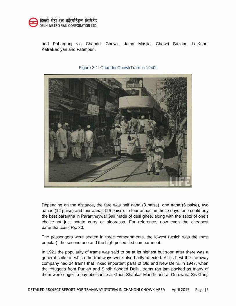
Figure 3.1: Chandni ChowkTram in 1940s
Depending on the distance, the fare was half aana (3 paise), one aana (6 paise), two aanas (12 paise) and four aanas (25 paise). In four annas, in those days, one could buy the best parantha in ParantheywaliGali made of desi ghee, along with the sabzi of one’s
choice-not just potato curry or aloorassa. For reference, now even the cheapest parantha costs Rs. 30.
The passengers were seated in three compartments, the lowest (which was the most popular), the second one and the high-priced first compartment.
In 1921 the popularity of trams was said to be at its highest but soon after there was a general strike in which the tramways were also badly affected. At its best the tramway company had 24 trams that linked important parts of Old and New Delhi. In 1947, when the refugees from Punjab and Sindh flooded Delhi, trams ran jam-packed as many of them were eager to pay obeisance at Gauri Shankar Mandir and at Gurdwara Sis Ganj,
DETAILED PROJECT REPORT FOR TRAMWAY SYSTEM IN CHANDNI CHOWK AREA April 2015 Page |6
opposite the Fawarra (fountain). Obviously there were many Sikhs among them, carrying swords, spears and shields, something the local populace found intimidating, until their fears were calmed by the tram conductors who welcomed the opportunity as heaven-sent for good profits.
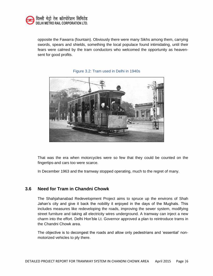
Figure 3.2: Tram used in Delhi in 1940s
That was the era when motorcycles were so few that they could be counted on the fingertips-and cars too were scarce.
In December 1963 and the tramway stopped operating, much to the regret of many.
3.6 Need for Tram in Chandni Chowk
The Shahjahanabad Redevelopment Project aims to spruce up the environs of Shah Jahan’s city and give it back the nobility it enjoyed in the days of the Mughals. This
includes measures like redeveloping the roads, improving the sewer system, modifying street furniture and taking all electricity wires underground. A tramway can inject a new charm into the effort. Delhi Hon’ble Lt. Governor approved a plan to reintroduce trams in the Chandni Chowk area.
The objective is to decongest the roads and allow only pedestrians and ‘essential’ non-motorized vehicles to ply there.
DETAILED PROJECT REPORT FOR TRAMWAY SYSTEM IN CHANDNI CHOWK AREA April 2015 Page |7
Over the years, many traffic management strategies have been tested to decongest the crowded Chandni Chowk area but the results have proved far from satisfactory. It needs a non-polluting, cost-effective mode of transport that will not be expensive for the passengers, and the example is the long-serving Calcutta Tramways.
Trams provided many advantages. They are eco-friendly since they run on electricity and life expectancy is high. Since maintenance is low-cost, the fare too can be kept to a minimal. Trams can run at higher speeds if allowed to move unhindered. The previous section lists several advantages of tramway systems.
Delhi Pwd has been tasked with the rebirth of the tram system and have associated the Delhi Metro Rail Corporation for Technical paternership. The report provides the details of all aspects including Technical know how of tram system in Chandni Chowk area.
For many trams in Chandni Chowk area, it will be necessary to make Chandni Chowk, Khari Baoli and Naya bazaar marg as no vehicle and no rickshaw zone during tram operation time from morning 6 am to night 10 p.m. In case the above discipline lacks, utility of tramway system will jeopardized.
DETAILED PROJECT REPORT FOR TRAMWAY SYSTEM IN CHANDNI CHOWK AREA April 2015 Page |1
CHAPTER- 4
SYSTEM SELECTION
4.1 Permanent Way
4.1.1 Track Gauge
The following assumptions have been adopted:
Track gauge will be Standard Gauge of 1,435 mm measured between the inner (gauge) sides on the heads of the rail at a distance of 14 mm below the top.
Gauge widening in curves is not normally applied. However, if gauge widening is applied in areas of tight curves and crossing works, the gauge widening will be compatible with the rail type and the wheel profile. Gauge widening will be decided at stage of detailed design.
The entire corridor has two-way tracks.
4.1.2 Track Geometry
The track in general is at grade except it is elevated on S.P Mukherji marg (Chainage from 2040m to 4000m).
Details of Track geometry are given in chapter 5, Civil Engineering.
4.1.3 Station Platforms
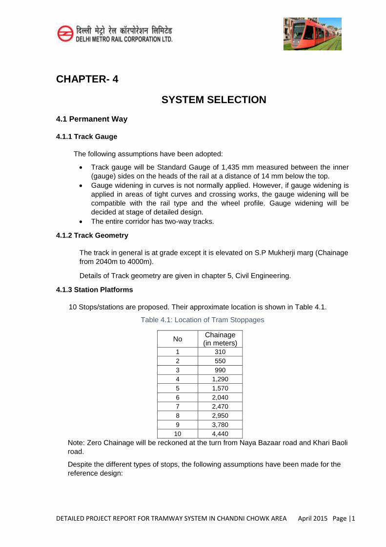
10 Stops/stations are proposed. Their approximate location is shown in Table 4.1. Table 4.1: Location of Tram Stoppages
No Chainage (in meters)
1 310 2 550 3 990 4 1,290 5 1,570 6 2,040 7 2,470 8 2,950 9 3,780
10 4,440 Note: Zero Chainage will be reckoned at the turn from Naya Bazaar road and Khari Baoli road.
Despite the different types of stops, the following assumptions have been made for the reference design:
DETAILED PROJECT REPORT FOR TRAMWAY SYSTEM IN CHANDNI CHOWK AREA April 2015 Page |2
All platforms and associated track alignment will be straight. Straight tracks will run along the full length of the platform with a desirable extension beyond both ends of the platform.
Horizontal and vertical curves will not be used at stations. Track cant at platforms is not permitted.
Details of station types with typical cross sections are given in Chapter 5, Civil Engineering.
4.1.4 Turnouts, Switches and Crossings
Switches and crossings will be manufactured to the specific requirements of each junction and will not normally allow for vertical curves over their length. The control equipment is to be located nearby and the activators will be buried in the road, usually between adjacent to the rails.
Switches and crossings will preferably be located on straight track. Switches and crossings will not be located on vertical curves. 1:6 with 50m radius turnout will be used. 1:4 with 35 m radius turnout could be
considered at constrained locations. For depot track, 1:4 with radius turnout will be used. Switches (and crossing) will not be located in pedestrian areas to prevent them
from having their feet caught by the moving point blade. Switches will not be located in areas of heavy crossing road traffic that could
damage them.
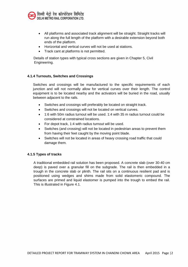
4.1.5 Types of tracks
A traditional embedded rail solution has been proposed. A concrete slab (over 30-40 cm deep) is paved over a granular fill on the subgrade. The rail is then embedded in a trough in the concrete slab or plinth. The rail sits on a continuous resilient pad and is positioned using wedges and shims made from solid elastomeric compound. The surfaces are primed and liquid elastomer is pumped into the trough to embed the rail. This is illustrated in Figure 4.1.
DETAILED PROJECT REPORT FOR TRAMWAY SYSTEM IN CHANDNI CHOWK AREA April 2015 Page |3
Figure 4.1: Concrete slab with trough
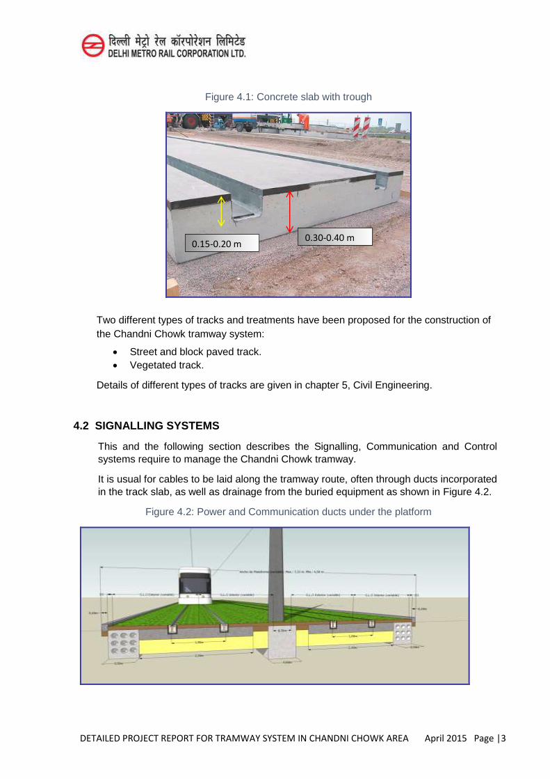
Two different types of tracks and treatments have been proposed for the construction of the Chandni Chowk tramway system:
Street and block paved track. Vegetated track.
Details of different types of tracks are given in chapter 5, Civil Engineering.
4.2 SIGNALLING SYSTEMS
This and the following section describes the Signalling, Communication and Control systems require to manage the Chandni Chowk tramway.
It is usual for cables to be laid along the tramway route, often through ducts incorporated in the track slab, as well as drainage from the buried equipment as shown in Figure 4.2.
Figure 4.2: Power and Communication ducts under the platform
0.30-0.40 m 0.15-0.20 m

DETAILED PROJECT REPORT FOR TRAMWAY SYSTEM IN CHANDNI CHOWK AREA April 2015 Page |4
In the Operation, tramways are driven on line of sight like a road vehicle. The driver is responsible for proceeding at a safe speed and for stopping short of any obstruction, including another tram ahead as well as a road vehicle or pedestrian on the track.
This section focuses on the elements of signalling and telecommunications vehicle and also includes information about the location system light rail. Selective detectors can locate trains and integrating this information with SAE (System to Assist the Operations), give priority to tram crossings with road traffic.
The provision of signalling equipment inside the vehicle and on the outside associated infrastructure could be summarized as follows:
In the vehicle: - System odometry - Antenna System Operation Assistance Programme (OAP) - Processor (OAP) - TETRA communication system
Outside the vehicle
- Screening systems for locating the tram - Beacons (OAP) - Signs Tram 3 aspects LED technology. - TETRA communication system
4.2.1 Vehicle Location system
The main function of the tramway location system is to provide a method for the detection of tramway vehicles in movement in specific points placed of the track.
The system proposed is based on selective detectors. This system allows to detect the presence of the vehicle next to a road crossing. An electronic device is established in the measuring cabinet of traffic.
Normally two symmetrical sets are placed so that not only the presence of the wheel is detected, but also the direction of the movement.
For what it is the OAP, every vehicle has an odometer, and in the line there will be located a series of beacons OAP to readjust the system of odometers and to correct diversions that could take place (be produced) for the wear of the wheels.
Across the infrastructure of mobile communications, every vehicle reports from its position to the Operation Control Centre (OCC).
4.2.2 Road Signalling
In the road signalling system, the OCC does not exercise any control on the vehicles .Driver is the one who is responsible for safety in the system of driving at sight. It is necessary to outline that the speed of traffic of the vehicles is limited to 50 km/h. Additional speed limit signposts will be implanted where ever required.
DETAILED PROJECT REPORT FOR TRAMWAY SYSTEM IN CHANDNI CHOWK AREA April 2015 Page |5
In those zones where the visibility is limited, suitable speed limit will be imposed so that a train could stop short of obstruction met if any suddenly.
The tramway location system will be connected to the urban traffic control center.
Some signalling is still required to establish priority at junctions and on any bidirectional tracks. This is closely integrated with the traffic signals on shared and intersecting highways. To avoid confusion with road and railway signals, tramway signals would consist of white bars, horizontal for stop, vertical for proceed if safe to do so, and inclined for a divergence to left or right.
The elements of the subsystem traffic light control are:
Tram traffic light. Vehicles and pedestrians traffic lights. Tram signs. Tram detectors devices. Traffic light regulators.
4.3 Communication system
The communication system necessary to operate and control the tramway system requires several optical fibre rings, Traffic mapping SDH equipment with both Ethernet as PDH; interface cards Fast Ethernet creating VLANs and digital splitters PDH to provide data.
Each ring is constituted by optical fiber stands two independent on both sides of the track paths, so that in case of fiber breakage an alternative route is established in the other direction of the ring. This architecture allows the system full redundancy of SDH network.
The SDH network provides the services listed below:
Automatic Telephony Intercom Radiotelephone Redundant LAN Traffic Remote Automatic Train Control (ATC) Remote Power Control LAN redundant Substations and Switchgear Remote Control Nonessential services LAN Toll System Passenger Address system Chronometer Visual Displays Facilities Remote control CCTV LAN Closed Circuit Television (CCTV).
DETAILED PROJECT REPORT FOR TRAMWAY SYSTEM IN CHANDNI CHOWK AREA April 2015 Page |6
Each stop will have IP communication networks for each of the services indicated above.
4.3.1 CCTV
It shall consist of a LAN ethernet IP network for transmission of images captured by the cameras at each station to the OC. Network shall be dimensioned to provide the ability to simultaneously access all cameras of the network cameras.
4.3.2 Remote ATC
This remote control network is defined as essential for the proper functioning of the Tramway system. Its drop would mean the degradation of Tram service or even its total interruption.
By reason of the foregoing, this network is reinforced with a duplicate in its entirety to ensure permanent connection of each station with the PC Candall users or checks will be conducted to both networks simultaneously.
Also, this network has two different connections through equipment other than transport network. With all this, it is ensured connecting the station with the OCC by "hardware" dedicated and different for each of the connections eliminating possible points of failure.
4.3.3 Remote Substations and Switchgear
This remote control network is defined as another essential key of the tramway system. The same Remote ATC standards will be applied.
4.3.4 Non-essential services
An exclusive network for toll services, control facilities, public address, visual display sand timing, all those that remain important for the proper operation of the tram, are not essential since the loss of any of these services in a stop doesn’t imply an interruption of
the tramway.
This network will have a single connection to the transmission network SDH tram. To support TETRA radio services to be implemented on the tram, an IP network is not used, but the signal of the radio systemonE1signals will be run directly. Voice services (automatic telephony and intercom) are integrated within a PDH hierarchy integrating all channels of the stoponE1, whichwill be integrated within the SDH node through digital splitters.
4.3.5 Radio Communications
The Radiotelephony system allows two kinds of communications:
Communication between OCC operators and drivers of trains .This can transmit orders of action ,giving performance criteria to mishaps or emergencies, informing staff of driving a train ,inform passengers linking the radio telephony and PA system, etc.
Between PCC operators and maintenance and security personnel.
DETAILED PROJECT REPORT FOR TRAMWAY SYSTEM IN CHANDNI CHOWK AREA April 2015 Page |7
The radio transmission system is common to both subsystems, working in separated channels.
Radio channels for communication will be integrated, in an emergency, the fire department and police stations.
Following the recommendations and current trends the system used is the TETRA (TRANSEUROPEAN Trunking Radio) system.
To provide coverage line, a single base station from a central location ensures communications with the board and is portable across multiple omni direction antennas installed on computers when adversity arises.
For communication from the Command Post with train drivers the following equipment is required:
Based radio station Radio equipment on board trains Central telephone station in the OCC Switching System
This equipment (except on board equipment) is common to that used for maintenance and security. The train radio system will also be interconnected with the PA system and visual displays on board.
Security personnel and maintenance remains connected to the OCC through its radio telephone system. It is also included as standard equipment for staff for mobile terminals, which include specific keys for emergency communications.
4.4 Passenger Information system
The passenger information system will consist of the following subsystems:
Public Address system Visual displays and timing Intercom
The first two subsystems will be managed centrally by the OCC (Operation Central Control), allowing the operation assistance system (OAS)submit the appropriate commands to those subsystems so that passengers are informed promptly of time, waiting for the arrival of the next train or arrival and destination. The OAS issues the appropriate commands to the computer local control of each of the stops, which will send the appropriate commands to both subsystems to produce the corresponding messages through the system either speakers or through Visual displays.
DETAILED PROJECT REPORT FOR TRAMWAY SYSTEM IN CHANDNI CHOWK AREA April 2015 Page |8
4.4.1 Public Address system
The public address system permit the emission of messages to any point in the network, either selectively or simultaneously for the dissemination of information on incidents or informational messages about events, user recommendations, etc. These messages can be broadcast live or recorded for broadcast at certain times, every so often, etc.
Passenger information systems must take into account as far as practicable, the needs of those with poor hearing, sight or cognitive skills.
The Public Address system must be based on criteria of simplicity of use, reliability of the elements of sound installation and full control of the system is composed. It is a zoned system (one for each direction of travel).
The system will integrate all the components within a single control such that the interaction between the user / system controller and the system itself will be made, simply through a computer in the communication room. This room will have buttons to tell us the different areas of the circuit, so that one may choose only specific areas for the public address or the whole system.
The Operation Central Control will have access to all areas of absolute priority at any time.
The system shall meet the following sound setting:
Sound pressure level: The team will be able to generate levels of about 105 dB. Bandwidth: The minimum bandwidth required is 80 Hz to 16 KHz. Uniformity of coverage: Coverage must be less than 10 dB. Intelligibility: Good intelligibility values (0.65 RASTI).
The public address sound system will provide processing and transmission of digital audio signals through a single network system. Audio transport system will be implemented in digital format, except the lines of 100 V from the power amplifiers. It is possible to use the system with or without a PC connected to the network controller. The network controller will be based on Web technology.
The public address system will be integrated into network and its configuration is as follows:
Network controller, which controls and monitors all system activities. Automatic messages stored in the network controller could be activated by either in put or control stations calls.
Stations calls, which can initiate any action on the system. The system will offer the ability to provide custom call stations using standard hardware available.
Audio expander to provide audio inputs ,audio outputs, control inputs and outputs for additional control. The system will have audio outputs that can be used to record emergency announcements. Open for interfacing with systems of other
DETAILED PROJECT REPORT FOR TRAMWAY SYSTEM IN CHANDNI CHOWK AREA April 2015 Page |9
manufacturers to report any changes occurring in the state of public address system interface will be included.
Amplifiers. Channel amplifiers provide audio outputs 100 V. The types of power amplifiers will be 1 or 2 x 500 W x 250 W.
Speakers
Other subsystems to take into account are:
‘Help point’ which can automatically announce service information when a button
is pressed, or put passengers in communication with the controller. ‘Emergency button’, usually integrated with the help point, but with a separate
button to put in a priority call and point CCTV cameras towards the caller.
4.4.2 Visual displays and Timing
A type of remote indicator is considered to be installed at all stops. The remote indicator is installed on each side of the stop/station for each direction.
The Visual displays will have no multiplexed LCD screens so that they ensure excellent lateral view (with an opening close to 160) and a good contrast in daylight. Also they will have backlight for easy reading in the dark. Furthermore, visual displays are turned on without showing any information, the light will turn off automatically after a certain time without receiving any messages from the system of local control.
The operating range of TV indicators should be - 20 ° C to + 70 ° C, with a resistance to humidity of 90% at 40 ° C. The Visual displays must be robust against electro-magnetic interference so that the passage of trams don’t affect the sharpness of the messages. Also they will have due vandal protection.
The local control computer station sent messages via local network to the TV indicators. The messages to appear on TV either by orders of SAE, traffic operator, or based on local computer programming. Likewise, the computer will monitor the status of remote indicators, reporting incidents to the OCC.
o The Visual displays should be able to show the following information for three trains simultaneously:
o Time of arrival of the next train (minute wait for the arrival). o Destination of the next train. o Current time. o Warnings, notices and messages
4.5 Ticketing System
Many different ticketing systems have been implemented worldwide. Their design usually depends on topics like tradition, other systems available in the project area, city,
DETAILED PROJECT REPORT FOR TRAMWAY SYSTEM IN CHANDNI CHOWK AREA April 2015 Page |10
region, chances of integration with other modes of traffic and finally, with available room in the stops.
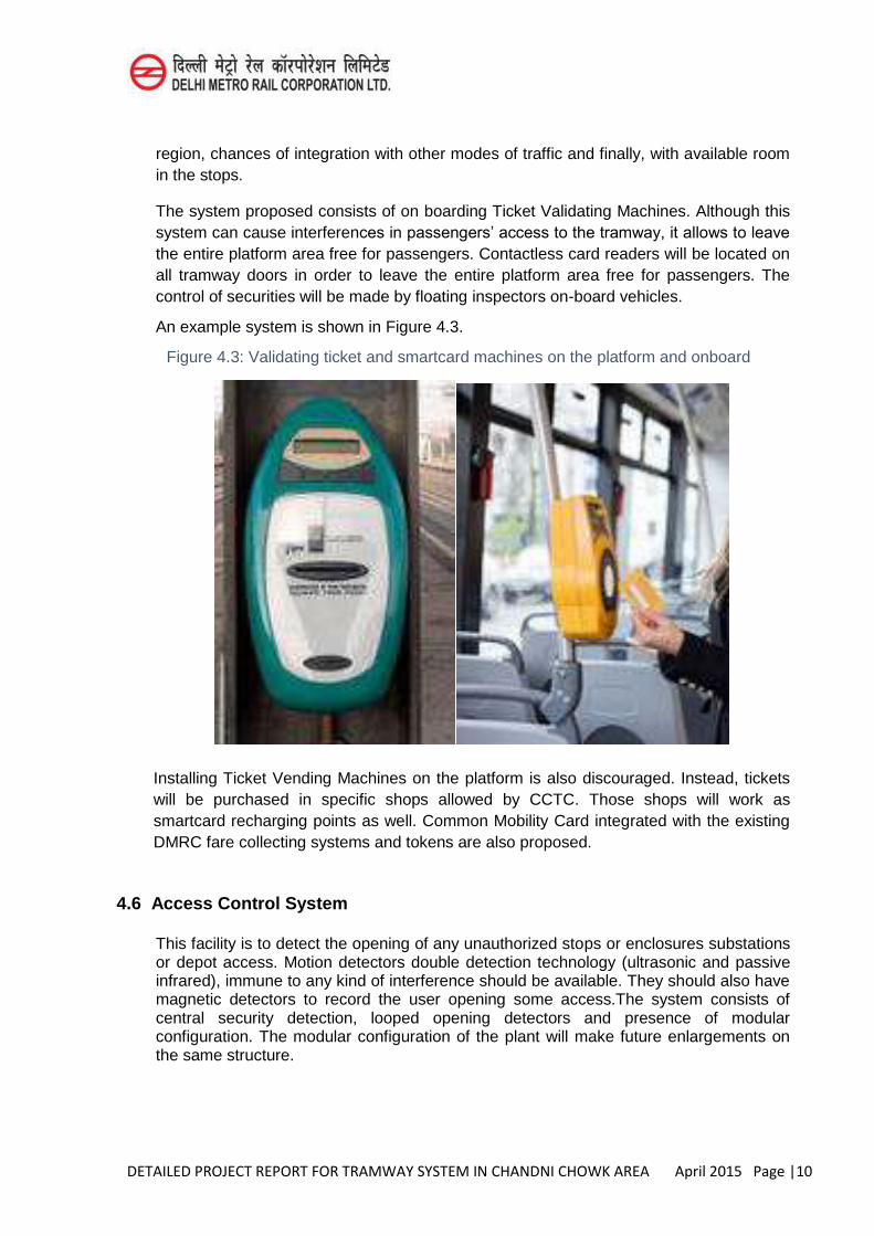
The system proposed consists of on boarding Ticket Validating Machines. Although this system can cause interferences in passengers’ access to the tramway, it allows to leave
the entire platform area free for passengers. Contactless card readers will be located on all tramway doors in order to leave the entire platform area free for passengers. The control of securities will be made by floating inspectors on-board vehicles.
An example system is shown in Figure 4.3.
Figure 4.3: Validating ticket and smartcard machines on the platform and onboard
Installing Ticket Vending Machines on the platform is also discouraged. Instead, tickets will be purchased in specific shops allowed by CCTC. Those shops will work as smartcard recharging points as well. Common Mobility Card integrated with the existing DMRC fare collecting systems and tokens are also proposed.
4.6 Access Control System
This facility is to detect the opening of any unauthorized stops or enclosures substations or depot access. Motion detectors double detection technology (ultrasonic and passive infrared), immune to any kind of interference should be available. They should also have magnetic detectors to record the user opening some access.The system consists of central security detection, looped opening detectors and presence of modular configuration. The modular configuration of the plant will make future enlargements on the same structure.
DETAILED PROJECT REPORT FOR TRAMWAY SYSTEM IN CHANDNI CHOWK AREA April 2015 Page |11
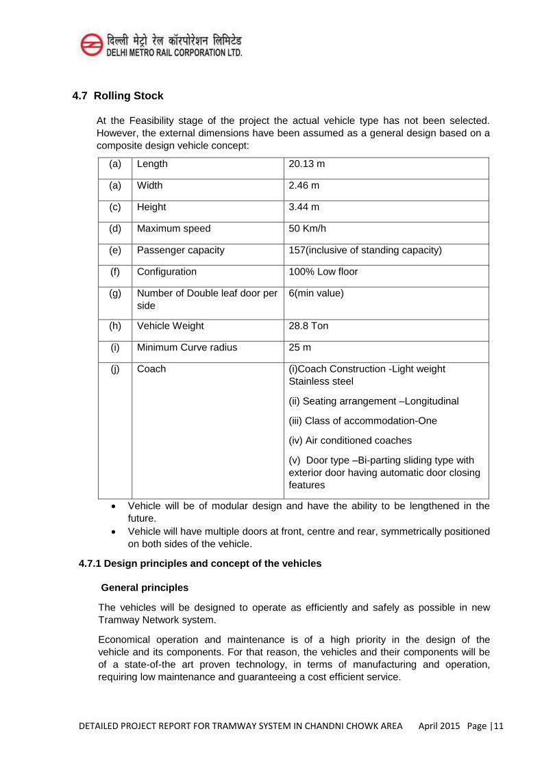
4.7 Rolling Stock
At the Feasibility stage of the project the actual vehicle type has not been selected. However, the external dimensions have been assumed as a general design based on a composite design vehicle concept:
(a) Length 20.13 m
(a) Width 2.46 m
(c) Height 3.44 m
(d) Maximum speed 50 Km/h
(e) Passenger capacity 157(inclusive of standing capacity)
(f) Configuration 100% Low floor
(g) Number of Double leaf door per side
6(min value)
(h) Vehicle Weight 28.8 Ton
(i) Minimum Curve radius 25 m
(j) Coach (i)Coach Construction -Light weight Stainless steel
(ii) Seating arrangement –Longitudinal
(iii) Class of accommodation-One
(iv) Air conditioned coaches
(v) Door type –Bi-parting sliding type with exterior door having automatic door closing features
Vehicle will be of modular design and have the ability to be lengthened in the future.
Vehicle will have multiple doors at front, centre and rear, symmetrically positioned on both sides of the vehicle.
4.7.1 Design principles and concept of the vehicles
General principles
The vehicles will be designed to operate as efficiently and safely as possible in new Tramway Network system.
Economical operation and maintenance is of a high priority in the design of the vehicle and its components. For that reason, the vehicles and their components will be of a state-of-the art proven technology, in terms of manufacturing and operation, requiring low maintenance and guaranteeing a cost efficient service.
DETAILED PROJECT REPORT FOR TRAMWAY SYSTEM IN CHANDNI CHOWK AREA April 2015 Page |12
All regulations with regards to fire protection, environmental protection and accident prevention must be fully satisfied.
To the extent possible, all materials to be used in vehicles will be recyclable. Manufacturers will supply a list containing all used materials, which will identify and describe the procedure to be utilized for the successful recycling of each individual material of each item of equipment.
Design Requirements
In general, the vehicles will have to be suitable for their intended use.
The Manufacturers will design and prove through the performance of the appropriate tests, that the vehicles will operate in the whole network, future extension lines, the depot, stabling facilities and workshops and the depot access tracks, under all loading conditions. Moreover, vehicles will be compatible with the communication and information systems of the existing network.
The design of the vehicle will fulfil the following basic requirements:
Safe Operation Provision for the safe use of disabled and people with special needs, aged persons and passengers
travelling with children Low operating and maintenance costs (i.e. easy access and replacement of modules, components
and equipment) Energy-efficient High ride quality (x,- y,- and z-direction) and passenger comfort Minimum noise and vibration during operation and running The vehicles are to be provided with high level of protection against vandalism (selection of
materials, painting, seats, etc.) Easy recognition of worn components and failed systems Interchange ability of all modules, components and equipment between vehicles Environment-friendly; with no thermal or electromagnetic influence of components (EMC) on other
systems operating adjacent to the vehicle Suitability for its intended operation, with favourable ergonomic maintenance and operating
conditions The passenger compartment and the driver's cab will have the required thermal and sound
insulation The vehicles will have a modern exterior and interior design of high aesthetics
Standards and Regulations
The vehicles will conform to International standards.
Vehicle Type
The vehicle to be supplied will be of a Low Floor type over the whole passenger compartment. Νo interior steps are allowed, although the floor may have a small inclination. The vehicle will be articulated and capable of bi-directional drive.
The vehicle will include a fully equipped driver-cab in both directions, in order to ensure full operation, control and performance of the vehicle.
DETAILED PROJECT REPORT FOR TRAMWAY SYSTEM IN CHANDNI CHOWK AREA April 2015 Page |13
Arrangement of the important equipment
The components to be used will be of a proven in-service design. The design will ensure the minimum wear of the wheel-rail system and low maintenance and operations costs.
Driving concept
The traction system will convert the 750V DC line voltage from the overhead supply / APS system into 3-phase electrical power and will drive the traction motors. IGBT technology will be employed for the traction motor inverter and AC traction motors will be installed in the vehicle. The electronic controls will be equipped with 32-bit or better microprocessors.
A regenerated energy scheme will be employed in the braking concept. The traction system will, during braking, regenerate electrical power to feed the overhead line and for use in vehicle loads as well, provided that the overhead line is receptive; e.g. another vehicle is requiring power at the same time. Should the line not be receptive, energy will be dissipated at the on-board braking resistors.
Wheel Profile
During the early days of the design phase, the Manufacturers will submit to Concerned Authority for approval a complete track/wheel interface study, which will positively identify the proper wheel profile to be finally applied, in order to increase passenger comfort, to ensure noise requirements and to minimise wheel/track wear, taking into consideration the complete track layout, the vehicle speed profile and load.
The wheels will have replaceable tyres.
Undercarriage design – bogie design
The type of undercarriage - bogie e.g. bogie, single wheels etc., will be proposed by the Manufacturer provided that:
Maximum wheel load complies with the values specified herein. Easy disassembling and replacement of relevant components (e.g. wheels, gears, motors,
disks, track brakes, shock absorbers etc.) and easy manual brake release is to be demonstrated.
12 wheels or 6 axles are foreseen (motorized and idle wheels included). However, the Manufacturer may propose his own wheel arrangement and wheel number and his own bogie configuration (with axes or independent wheels).
The Manufacturers will submit a technical description for the proposed bogie and wheel/axes layout. The number of the driving wheels/axes, as well as their related position will be determined by the manufacturer.
They will also include drawings regarding the driving and trailer bogies, their manufacturing material and method, their weight, the un-sprung mass loads, the wheel load distribution, the motor arrangement, accompanied by its supporting/fixing method on the bogies, the transmission scheme, suspension system, lubrication and sanding scheme, description of the measures that have been provided for regarding noise
DETAILED PROJECT REPORT FOR TRAMWAY SYSTEM IN CHANDNI CHOWK AREA April 2015 Page |14
mitigation due to the wheels’ rolling on running tracks, the bogies disassembly method from the tramway vehicle and their adjustment to alignment curves.
The Manufacturers will prepare a design based on the FE Analysis, in order to ensure the required structural integrity of the vehicles, as well as their strength against fatigue.
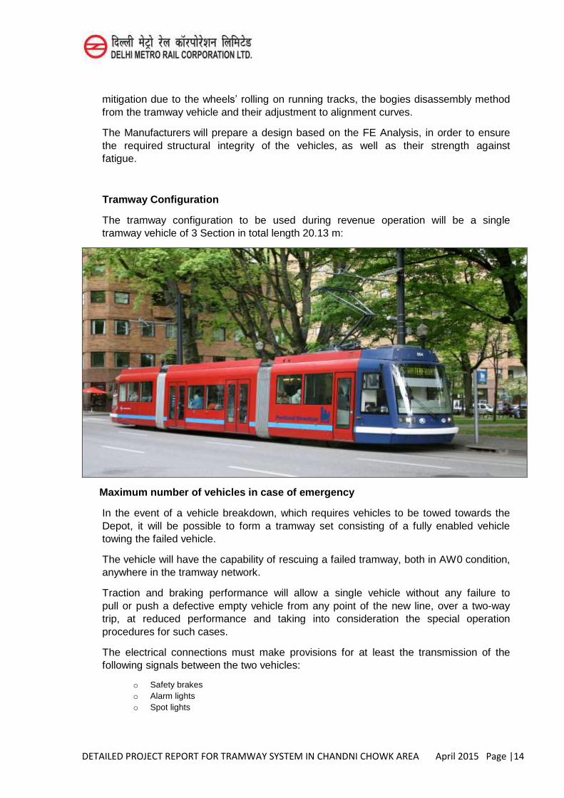
Tramway Configuration
The tramway configuration to be used during revenue operation will be a single tramway vehicle of 3 Section in total length 20.13 m:
Maximum number of vehicles in case of emergency
In the event of a vehicle breakdown, which requires vehicles to be towed towards the Depot, it will be possible to form a tramway set consisting of a fully enabled vehicle towing the failed vehicle.
The vehicle will have the capability of rescuing a failed tramway, both in AW0 condition, anywhere in the tramway network.
Traction and braking performance will allow a single vehicle without any failure to pull or push a defective empty vehicle from any point of the new line, over a two-way trip, at reduced performance and taking into consideration the special operation procedures for such cases.
The electrical connections must make provisions for at least the transmission of the following signals between the two vehicles:
o Safety brakes o Alarm lights o Spot lights

DETAILED PROJECT REPORT FOR TRAMWAY SYSTEM IN CHANDNI CHOWK AREA April 2015 Page |15
o Stop lights Horns o Brake release function o Communication among the driving areas
The vehicles will be equipped with coupling adaptors – of mechanical and electrical coupling - in case it is needed to satisfy the above requirement. The adaptors will be stored on each vehicle, on an easily accessible position and should be easily handled (mounted/dismounted) by a single person (driver).
The final configuration as well as the operational procedure of towing will be approved during the review of the final design.
Vehicle Life
The vehicles to be supplied will have a 30-year service life as a minimum.
Accessibility to Elderly and Persons with Special needs
The tramway vehicles will be fully accessible by Persons with Special Needs, including wheelchair passengers.
4.7.2 Operational Requirements
Vehicles will meet the requirements of this Specification and will prove their compliance during the testing and commissioning phase.
Vehicles will operate in the entire network, the connecting lines, inside the depot and in the workshop areas.
Passengers on-board the tramway vehicles
The tramway vehicles will be designed to carry passengers of d i f f e r en t ag e g r oups . Passengers might also be mobility impaired persons.
Provisions will be made for safe accommodation of baby carriages and wheel chairs. The tramway vehicles will carry passengers either familiar or unfamiliar with the system.
The vehicle will be designed to carry passengers in 30 seating capacity and 127 in standing capacity to take a overall of 157 passengers.
Headways and Operational Speed
The current passenger service time tables provides for 5 minutes headway between two consecutive tramway vehicles during peak hours. The mean time distance between two stops is assumed to be 75 seconds.
Through the simulations, the manufacturers will demonstrate the performance compliance with the respective specifications, which is to be verified at the testing phase. The detailed input parameters for the simulations will be approved by DMRC.
The maximum operational speed allowed is limited to 50 km/h.
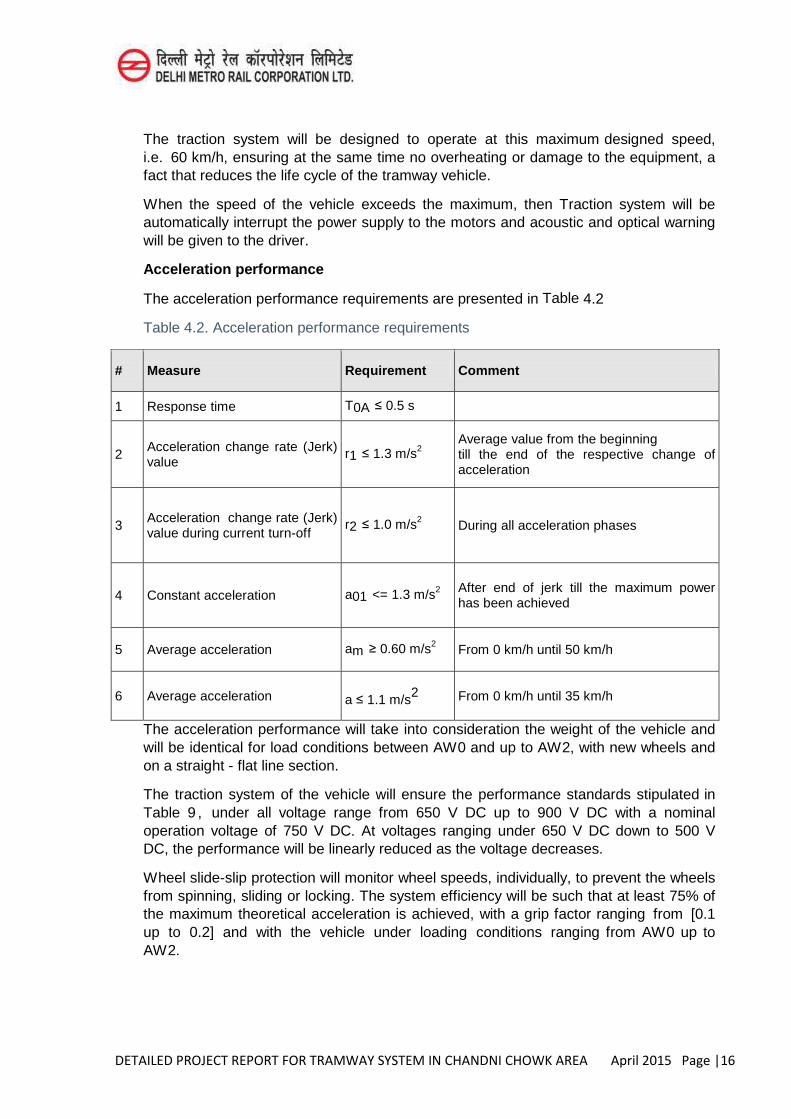
DETAILED PROJECT REPORT FOR TRAMWAY SYSTEM IN CHANDNI CHOWK AREA April 2015 Page |16
The traction system will be designed to operate at this maximum designed speed, i.e. 60 km/h, ensuring at the same time no overheating or damage to the equipment, a fact that reduces the life cycle of the tramway vehicle.
When the speed of the vehicle exceeds the maximum, then Traction system will be automatically interrupt the power supply to the motors and acoustic and optical warning will be given to the driver.
Acceleration performance
The acceleration performance requirements are presented in Table 4.2
Table 4.2. Acceleration performance requirements
# Measure Requirement Comment
1 Response time T0A ≤ 0.5 s
2 Acceleration change rate (Jerk) value
r1 ≤ 1.3 m/s2
Average value from the beginning till the end of the respective change of acceleration
3 Acceleration change rate (Jerk) value during current turn-off
r2 ≤ 1.0 m/s2 During all acceleration phases
4 Constant acceleration a01 <= 1.3 m/s2
After end of jerk till the maximum power has been achieved
5 Average acceleration am ≥ 0.60 m/s2 From 0 km/h until 50 km/h
6 Average acceleration a ≤ 1.1 m/s2 From 0 km/h until 35 km/h
The acceleration performance will take into consideration the weight of the vehicle and will be identical for load conditions between AW0 and up to AW2, with new wheels and on a straight - flat line section.
The traction system of the vehicle will ensure the performance standards stipulated in Table 9 , under all voltage range from 650 V DC up to 900 V DC with a nominal operation voltage of 750 V DC. At voltages ranging under 650 V DC down to 500 V DC, the performance will be linearly reduced as the voltage decreases.
Wheel slide-slip protection will monitor wheel speeds, individually, to prevent the wheels from spinning, sliding or locking. The system efficiency will be such that at least 75% of the maximum theoretical acceleration is achieved, with a grip factor ranging from [0.1 up to 0.2] and with the vehicle under loading conditions ranging from AW0 up to AW2.
DETAILED PROJECT REPORT FOR TRAMWAY SYSTEM IN CHANDNI CHOWK AREA April 2015 Page |17
Downgraded operation for acceleration
Should a propulsion system failure occur, resulting in 25% of the traction power not being available, and with the vehicle in load condition AW3, the vehicle will be capable of starting and clearing the sect ion.
If during traction and under all possible modes of operation, the vehicle moves backwards for a maximum of 0.5 meters or with a negative speed greater than 1.5km/h (whichever comes first), the vehicle will automatically apply the full service brakes, until it is stopped.
Braking performance
Unless otherwise specified herein, all braking performance will be compatible with EN13452-1 and will be tested in accordance with EN13452-2.
Service brake
Service braking is used to reduce speed or to stop the vehicle in an accurate and consistent manner throughout the line, in compliance with the comfort criteria. This braking will not cause regular and intensive stressing of elements subject to wear.
From the maximum down to the minimum speed that activates the mechanical braking to be determined in the design, service braking performance will be achieved using only electro-dynamic braking, in all conditions of line receptivity up to 100% (maximum regenerative brake). At low speed, electro-dynamic braking will be blended with the mechanical braking to stop the train, wheel slide-slip protection being operative.
Under partial receptivity conditions, the full electro-dynamic braking effort will be achieved with rheostat braking in complement. In non-receptivity conditions, full electro-dynamic braking effort will be achieved with rheostat braking.
The braking values are valid for new wheels, straight flat line, and maximum speed and with loaded vehicle according to EN13452-1 braking guide lines.
The following nominal performance levels (see Table 4.3 below) must be fulfilled by an empty vehicle and a vehicle in loaded condition AW2, and with all braking system in service. Whatever the speed at start of braking, up to maximum speed, the service braking performance will meet the requirements specified hereunder with all motor bogies in service, in a straight and levelled track.
The traction system of the vehicle will ensure the aforementioned regenerative electrical braking performance, under all voltage range of the Line from 750 V DC up to 900 V DC. At line voltages ranging under 750 V DC and down to 500 V DC, the performance of the regenerative electrical braking will be linearly reduced as the voltage decreases.
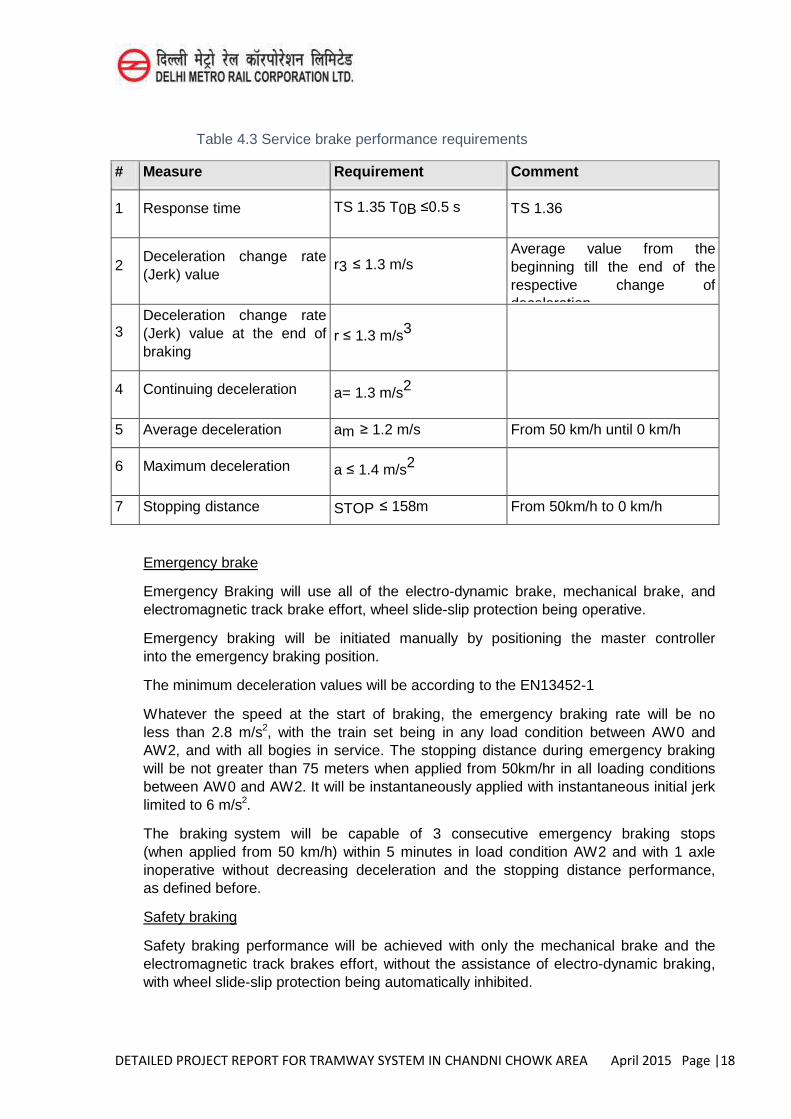
DETAILED PROJECT REPORT FOR TRAMWAY SYSTEM IN CHANDNI CHOWK AREA April 2015 Page |18
Table 4.3 Service brake performance requirements
# Measure Requirement Comment
1 Response time TS 1.35 T0B ≤0.5 s TS 1.36
2 Deceleration change rate (Jerk) value
r3 ≤ 1.3 m/s Average value from the beginning till the end of the respective change of deceleration
3 Deceleration change rate (Jerk) value at the end of braking
r ≤ 1.3 m/s3
4 Continuing deceleration a= 1.3 m/s2
5 Average deceleration am ≥ 1.2 m/s From 50 km/h until 0 km/h
6 Maximum deceleration a ≤ 1.4 m/s2
7 Stopping distance STOP ≤ 158m From 50km/h to 0 km/h
Emergency brake
Emergency Braking will use all of the electro-dynamic brake, mechanical brake, and electromagnetic track brake effort, wheel slide-slip protection being operative.
Emergency braking will be initiated manually by positioning the master controller into the emergency braking position.
The minimum deceleration values will be according to the EN13452-1
Whatever the speed at the start of braking, the emergency braking rate will be no less than 2.8 m/s2, with the train set being in any load condition between AW0 and AW2, and with all bogies in service. The stopping distance during emergency braking will be not greater than 75 meters when applied from 50km/hr in all loading conditions between AW0 and AW2. It will be instantaneously applied with instantaneous initial jerk limited to 6 m/s2.
The braking system will be capable of 3 consecutive emergency braking stops (when applied from 50 km/h) within 5 minutes in load condition AW2 and with 1 axle inoperative without decreasing deceleration and the stopping distance performance, as defined before.
Safety braking
Safety braking performance will be achieved with only the mechanical brake and the electromagnetic track brakes effort, without the assistance of electro-dynamic braking, with wheel slide-slip protection being automatically inhibited.
DETAILED PROJECT REPORT FOR TRAMWAY SYSTEM IN CHANDNI CHOWK AREA April 2015 Page |19
The safety braking will have an average deceleration value of a ≥1.4 m/s2 initial speed and under AW2 load conditions.
Downgraded operation for braking
The braking system will be capable of sustaining a vehicle in AW2 load condition, in operation, with 1 axle in failure, maintaining the above required performances.
Body suspension
The car body is to be suspended in the vertical and horizontal directions. The suspension system should ensure safe trips, as per Standard EN 12299. The suspension will be designed based on the vibration conditions, which apply under the maximum speed on a straight track under normal track conditions.
Vehicle weight and wheel load
The wheel load of each wheel will not exceed 60 KN under AW4 loading condition. The manufacturers will specify the maximum weight of the vehicle as well as the static wheel load for each wheel on a single vehicle under all load conditions from AW0 to AW4.
Protection against derailment
The Manufacturers will describe the protection against derailment features of the vehicle.
The Manufacturers will provide a complete derailment study during the Final Design review period. The study will include calculations of protection against derailment, especially of “unloading” of wheels gradients with empty vehicle.
The worst condition is to be used i.e. very slow departure from a curve of the highest gradient in the system. The calculation will take into consideration the vehicle and infrastructures under the maximum wear conditions, as well as under new conditions.
The worst dynamic condition is also to be taken into account. The derailment study will make explicit reference to the case of pushing/pulling a defective vehicle by another vehicle in operation.
The parameters’ study will provide conclusions as to the maximum permitted speeds under certain conditions, as well as to the allowable wheel wear limits for safe operation.
The study will conclude to the operational procedure of re-railment as well as to the necessary precautions or measures that need to be introduced during the re-railment procedure under all possible derailment conditions. Through Side Doors using retractable staircases are proposed during Emergency Derailment
Vehicle envelopes
The vehicle must adhere to the gauge restrictions detailed.
The Manufacturers will provide details of the following gauges based on which the vehicle will be manufactured:
DETAILED PROJECT REPORT FOR TRAMWAY SYSTEM IN CHANDNI CHOWK AREA April 2015 Page |20
Static envelope
Kinematic gauge
Platform Interface
The existing platform level is higher than the track level (TOR) by 275mm, while the horizontal distance of the platform from the track centre equals to 1,300mm. The aforementioned is subject to construction tolerances.
The vehicle floor level in the vehicle’s doors area, when the vehicle stops at the platform and is under AW2 loading condition, should be equal to or higher than the platform level.
The horizontal distance between the edge of the platform and the threshold of the vehicle doors will be equal to or smaller than 100mm. on straight track (+/- construction and operational tolerances).
Tramways manufacturers will submit the following:
A statement concerning the height difference between the vehicle floor level in the vehicle’s doors area and the platform’s edge level, when the vehicle stops at the platform for all loading conditions (AW0 – AW4).
A statement of compliance of the maximum horizontal distance of the threshold of the vehicle doors from the platform, with the permitted one.
Noise and vibration levels
General
This section defines the performance requirements for the noise and vibration levels that will be achieved in the whole network and the Depot.
All equipment, sub-components, supporting framework and all fastening devices (bolts, welds, rivets, vibration isolators, etc.) will be designed to withstand the periodic, random impact loads and vibrations associated with a rugged railcar environment without sustaining damage or malfunction. Such equipment will comply with the requirements of IEC standard 61373, IEC standard 60077, or related EN standard, whichever is the more stringent.
All requirements of this document as regards the noise and vibration levels will be checked through the respective type tests.
External noise
The level of noise generated by the tramway vehicles must be compatible with its operation in urban areas and must not create any unacceptable disturbance.
The external noise levels of the vehicle will be measured per ISO 3095 and on the basis of the following conditions:
Stationary Vehicle in an open area
Stationary vehicle on an at-grade, flat track, in an open area, with all sub-systems operating simultaneously, each under its nominal power. As per ISO 3095, microphones
DETAILED PROJECT REPORT FOR TRAMWAY SYSTEM IN CHANDNI CHOWK AREA April 2015 Page |21
will be installed on either side of the vehicle, spaced – horizontally – at 7.5m from the centre of the track and at TOR levels 1.2 and 3.5m.
Running Vehicle in an open area
The vehicle will run on a level, tangent, at-grade track, in an open area, with clean, smooth rails, with all sub-systems operating simultaneously, each under its nominal power.
Consecutive and separate external noise level measurements will be conducted for vehicles running on road surface asphalt embedded tracks, on grass and on ballasted tracks.
The microphones’ layout will be identical to the layout to be utilized during the measurements of external noise generated by a stationary vehicle.
Three types of vehicle movements will be assumed, as regards the external noise measurements:
Passing by vehicle under stabilized speeds: the vehicle will pass by the measurement point at stabilized speeds equal to 40 and 60 km/h + 5%.
Vehicle start up: the vehicle will start from a stop using the maximum traction power causing spinning of its wheels until it reaches the speed of 30km/h; the vehicle will keep this speed level until the entire tramway vehicle – lengthwise – passes by the measurement point.
Vehicle deceleration: the vehicle running at a speed of 30 km/h, when approaching the measurement point, will decelerate until it stops using the normal braking system.
Internal Noise
The design of the vehicle will minimize internal noise, both in the passenger compartment and in the driving cab. The noise levels will be measured per ISO 3381:
Stationary Vehicle in an open area
Stationary vehicle on an at-grade track, in an open area, with all sub-systems operating simultaneously, each under its nominal power.
Microphones will be installed inside the vehicle along its symmetry axis at a height of 1.6m. from the vehicle floor. The number of the microphones and their exact location will be subject to DMRC approval.
Running Vehicle in an open area
The vehicle will run at stabilized speeds of 40 and 60 km/h on a level, tangent, at- grade, clean and smooth track, in an open area, with all sub-systems operating simultaneously, each under its nominal power.
Consecutive and separate internal noise level measurements will be conducted for vehicles running at the two speeds mentioned above on road surface asphalt embedded tracks, on grass and on ballasted tracks.
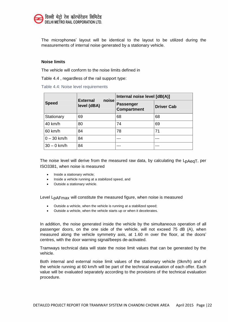
DETAILED PROJECT REPORT FOR TRAMWAY SYSTEM IN CHANDNI CHOWK AREA April 2015 Page |22
The microphones’ layout will be identical to the layout to be utilized during the measurements of internal noise generated by a stationary vehicle.
Noise limits
The vehicle will conform to the noise limits defined in
Table 4.4 , regardless of the rail support type:
Table 4.4: Noise level requirements
Speed External noise level (dBA)
Internal noise level [dB(A)]
Passenger Compartment
Driver Cab
Stationary 69 68 68
40 km/h 80 74 69
60 km/h 84 78 71
0 – 30 km/h 84 --- ---
30 – 0 km/h 84 --- ---
The noise level will derive from the measured raw data, by calculating the LpAeqT, per ISO3381, when noise is measured
Inside a stationary vehicle; Inside a vehicle running at a stabilized speed, and Outside a stationary vehicle.
Level LpAFmax will constitute the measured figure, when noise is measured
Outside a vehicle, when the vehicle is running at a stabilized speed; Outside a vehicle, when the vehicle starts up or when it decelerates.
In addition, the noise generated inside the vehicle by the simultaneous operation of all passenger doors, on the one side of the vehicle, will not exceed 75 dB (A), when measured along the vehicle symmetry axis, at 1.60 m over the floor, at the doors’
centres, with the door warning signal/beeps de-activated.
Tramways technical data will state the noise limit values that can be generated by the vehicle.
Both internal and external noise limit values of the stationary vehicle (0km/h) and of the vehicle running at 60 km/h will be part of the technical evaluation of each offer. Each value will be evaluated separately according to the provisions of the technical evaluation procedure.
DETAILED PROJECT REPORT FOR TRAMWAY SYSTEM IN CHANDNI CHOWK AREA April 2015 Page |23
Vibrations
With a stationary vehicle and its entire auxiliary equipment operating simultaneously and at its nominal power, no feature inside the vehicle can exceed the following vibration levels:
2.54 mm – peak to peak range for frequencies below 1.4 Hz. 0.01 g peak acceleration for frequency range from 1.4Hz to 20 Ηz. 0.762 mm/s – peak velocity for frequency range over 20 Ηz.
or, alternatively, with a stationary vehicle and its entire auxiliary equipment operating simultaneously and at its nominal power, no feature inside the vehicle can exceed the following vibration levels, as per ΕΝ 12299:
NMVx = 1.0
NMVy = 1.5
NMVz = 1.0.
Ride comfort
The ride comfort of the vehicles will be evaluated and tested in line with Standard EN 12299 for standees and seated passengers at straight and curved track sections. In any case, the vehicle will satisfy – as a minimum – the “Comfort” Index.
Special slipping conditions
Vehicles should be able to overcome adhesive condition due to weather conditions or any other external reasons. With the aid of their slip-slide protection .
Environmental conditions
The vehicles and all their equipment will operate satisfactorily in all environmental conditions that may be encountered in New Delhi
Adverse Weather Conditions
Tramway vehicles will operate through floodwater up to a depth of at least 100 mm above rail level. It will be detailed any restrictions for the operation in water depths above 100mm.
4.7.3 Energy Measurement
Manufacturers will ensure that all tramway vehicles are equipped with energy consumption measurement devices. The proposed devices must:
Be certified for billing by an Indian transport/ railway authority. Ensure Class 0.5R measuring accuracy, as per EN 50463-2 (Railway Applications – Energy
metering on board) Record absolute values of the consumed and regenerated energy
DETAILED PROJECT REPORT FOR TRAMWAY SYSTEM IN CHANDNI CHOWK AREA April 2015 Page |24
Perform sampling using properly or automatically adjusted time steps Have sufficient internal data storage capacity for at least 30 days Be interfaced with the tramway vehicle GPS system and record local coordinates/ vehicle position
at each measurement as per standard EN 50463-3 Be equipped with a communication protocol, compatible with the data collection and
transmission system of the vehicle through the wireless local Wi-Fi network of the Depot. Be equipped with the appropriate energy recordings analysis and processing software (energy
analysis software), supporting display functions compatible with the mapping system of the Tramway network (on the central PC at the Depot), capable of wireless data collection.
Be compatible with EN 50155 Standard (Railway Applications – Electronic Equipment used on rolling stock).
These measurements will be either displayed independently or they will be recorded and announced at the Drivers Display Unit by means of the Train Control and Management System (TCMS) of the vehicle.
The Manufacturers will submit the relevant certificates, manuals and the connection diagram of the aforementioned proposed device.
Apart from the aforementioned measuring devices, the TCMS system will have the possibility to measure the energy consumed at the traction power system and at the auxiliary power supply system independently, as well as break energy regeneration.
The above will be used during revenue service and during energy consumption tests, in line with article 15.
Provision for operation without power supply from the overhead catenary system, using batteries / super capacitors
Vehicles will be designed and equipment with all necessary provisions to accommodate batteries / super-capacitors, in order to perform standard Tramway line service trips which include sections of the line not powered by the overhead catenary.
The requirements related to the on board batteries/super capacitors will cover the vehicles operation on such line sections, including distances, stop locations , line gradient, etc.
The supply and installation of batteries/ super capacitors is not included in the scope of this tendered project.
Tramway vehicles will be capable of operating without being powered by an overhead catenary, but using batteries/ super capacitors.
In addition, taking into consideration that:
o The maximum speed of the vehicles on areas without an overhead catenary will be 50 km/h o Within areas without an overhead catenary, there will be sections where vehicles slow down
(e.g. close to signalled intersections) to achieve a speed of the order of 10km/h o There will be a number of unscheduled, unforeseen vehicles stops / starts. o Vehicle dwelling time at stops will be approx. 20 sec, and the battery/ super capacitor
system must be adequately recharged during this period. o During the summer, the average maximum ambient temperature in New Delhi is 40ºC, while
the absolute maximum temperature is even higher and there is direct solar radiation on the roof of the vehicles ; these factors are anticipated to influence the operation characteristics of the batteries / super capacitors
DETAILED PROJECT REPORT FOR TRAMWAY SYSTEM IN CHANDNI CHOWK AREA April 2015 Page |25
o All the remaining functional requirements of the tramway vehicle specifications, the Contactor will ensure the following:
o Structural / spatial layout of the foreseen installation of the batteries / super- capacitor on the vehicle
o Structural strength of the car-body to sustain the additional load of the batteries / super-capacitors
o Structural / spatial arrangement of the foreseen installation of the batteries / super-capacitors ensuring smooth drainage of storm-water or vehicle wash run-off water, without water accumulation points, with the batteries / super capacitors being present or not.
o Cable routings running from / to the batteries / super-capacitors to / from traction power, auxiliary power and control systems.
o Ensuring provisions for the installation of a ventilation / air-conditioning system of the battery sets and super-capacitors, should it be required, for their proper operation.
o Efficiency and dimensioning of motors and traction systems for compliance with the performance specifications, taking into consideration the additional weight or other requirements of the batteries / super-capacitors.
o Adequate number of unscheduled and unforeseen vehicles stops / starts o Expandability of the control – TCMS systems for monitoring all parameters related to the
operation and performance of the batteries / super-capacitors; and should they be installed, adequate provisions must be made for the additional “screens” on the Drivers Display Unit for the TCMS system.
o Design acceptance of the shifting of the centre of gravity of the vehicle. o Ability of the vehicle suspension system and bogies to bear the additional weight of the
batteries / super-capacitors. o Capacity and dimensioning of the on board traction, break energy regeneration, auxiliary
power systems, inverters and other electrical equipment, including all initial cabling, to support the presence and parallel operation of the batteries/ super-capacitors.
o Ensuring an adequate life cycle of the pantograph system of the vehicle, taking into consideration its increased operation cycle, due to vehicles’ entry/exiting in areas without overhead catenary.
o Possibility for energy saving through the batteries / super-capacitors - if and when they are installed - in combination with the traction, break energy regeneration, auxiliary power systems, inverters, etc., both in the line sections where power is supplied by an overhead catenary and where it is not.
o Electromagnetic compatibility of the on board equipment with the batteries/ super-capacitors.
o That Electromagnetic emissions from batteries / super-capacitors fall within the limits specified by the relevant railway standards and the present performance specifications.
o Safe operation of the batteries / super-capacitors, not posing any risks for passengers, the driver, passing-by pedestrians and properties (e.g. glass panels, private vehicles, etc.).
o Possibility to charge the batteries / super-capacitors from special 750 VDC feeding points at the Tramway stops. The feeding point can be located on the roof or underneath the vehicle’s floor.
o Possible future installation of the batteries / super-capacitors inside the vehicle’s dynamic clearance envelope and/or inside the minimum envelope occupied by the vehicle’s pantograph system at any location.
o That possible future installation of the batteries / super-capacitors can be implemented at the Tram Depot (i.e. without the need to have the vehicles transported to the manufacturing factory).
DETAILED PROJECT REPORT FOR TRAMWAY SYSTEM IN CHANDNI CHOWK AREA April 2015 Page |26
Track curves’ and cants’ limits
Vehicles will be able to operate at:
o A minimum curve radius: 25 m. At this point, the smooth operation of the vehicles must be ensured, probably with a speed reduction.
o Máximum longitudinal gradient: 8.5%.
4.7.4 Traction system
The vehicle will be so designed as the minimum remaining traction power following a single traction system failure (to the motor, inverter or respective inverter control unit) will be 75% of the nominal one. Traction systems at each body will be uniform and interchangeable.
The traction system will ensure that in the event of a 50% failure, the vehicle can return to the depot under its own power from any point on the alignment.
The traction system will be able to make any full round trip under the following conditions:
AW2 load ¾ of the propulsion system operative, ¼ inoperative
Line voltage not less than 650 V Available only the rheostatic brake Mechanical brake system acts on all axles.
Back-up hardwiring for critical control functions will be supplied.
A detail of the tramway vehicle performance and functions during back-up hard wire operation will be also supplied
The traction system will be energy-saving, by electric regeneration during electrodynamic braking.
Following information will be submitted:
Layout drawings and description/ characteristics of the traction system Traction system interface points Wheel diameter offset Equipment cooling system Traction motor disconnection system and removal method Description of the protection equipment against current input
Pantograph
The 750V (nominal) DC Power Supply will be fed to the vehicle from the overhead wire via a single pantograph, located on the vehicle roof. It is to be mounted in that way that the middle of the contact strip in working position is about the railway track middle axis and if possible about the pivot of the second or middle bogie.
The pantograph will be service-proven, single-arm design, capable of stable bi- directional operation at all specified vehicle speeds at all locations on the track and in all environmental conditions likely to be encountered.
DETAILED PROJECT REPORT FOR TRAMWAY SYSTEM IN CHANDNI CHOWK AREA April 2015 Page |27
The design of the pantograph will be such that it will not substantially increase the risk of de-wirement, contact with support structures or detrimental wear to the contact wire.
The shoe device and contact insert will be replaceable with common hand tools.
Means to reduce arcing between pantograph and overhead wire will be integrated and demonstrated in the design.
The pantograph raising and lowering circuit will be operable from any cab. The driver will have the possibility for manually unlatching, lowering and raising the pantograph in the event of a loss of power or control.
The final position of the pantograph will be mechanically locked and indicated on the driver’s panel. The presence of the overhead power supply voltage should be indicated in the driver’s panel.
The mean operational upward nominal force will be 80 N, adjustable in the range from 60N to 100N. Double contact strips with a radius of 10.000 mm are to be employed.
Pantograph components
The pantograph components and its wiring will adhere to the following principles:
Simple assembly Maintenance and service friendliness Improved electromagnetic compatibility (EMI) Short starting times Protection of the components against dirt and moisture High degree of availability and reliability Weight reduction for the entire vehicle Minimal amount of cabling work and plug-in connections Easiness of cleaning the pantograph mounting area All high voltage cables will have appropriate insulation. Easy replacement of worn out collector head
strips.
High Speed Circuit Breaker
The vehicle will be equipped with the appropriate High Speed Circuit Breaker (HSCB), which will provide the necessary protection to the traction system.
During the design and material selection stage, care will be taken to provide adequate protection from over voltage, overcurrent, ground fault and any other circuit protection deemed necessary to protect the traction system components (return of nominal 750V DC system current via improper paths).
The drive equipment will be protected against high transient voltage peaks from the power supply like lightning strokes.
Traction Control and Inverter
A suitably sized traction inverter will convert the 750 V DC power to variable voltage – variable frequency power and drive the traction motors, using state of the art IGBT power modules.
DETAILED PROJECT REPORT FOR TRAMWAY SYSTEM IN CHANDNI CHOWK AREA April 2015 Page |28
No less than 32-bit technology traction control system will control and monitor the drive units in accordance with the current motoring or braking reference values specified by the driver.
The traction control will be arranged to ensure optimized performance and ride characteristics, for instance jerk limitation by braking, wheel slip and slide protection when accelerating or decelerating, as well as monitoring of the permissible values and limitations concerning motor characteristics, acceleration and deceleration.
The Traction Control Unit (TCU) should be so housed that no outside dust ingress is possible. All hardware modules of the TCU unit will be secured safely in the retaining rack.
A built-in function should not allow the vehicle to exceed the maximum speed limit.
The Manufacturers will submit for approval a list of software settings permitted by the maintenance personnel. The wheel diameter values settings will be displayed, evaluated and eventually corrected through the data bus system.
For the reading of the TCU and all other electronic units required for troubleshooting an up-to-date diagnostic program will be delivered. Its detailed description will be submitted for approval.
The reading of the TCU data should also be enabled through the TCMS.
Traction Motors
The Manufacturer will determine the motor number and characteristics. The motors; operation will have been demonstrated in other Tramway networks. Motors will be three-phase alternating current asynchronous-motors of sufficiently calculated power; they must fulfil the demands of the EN 60349-2 (VDE 0115 part 400-2).
The Manufacturers will determine the type of cooling and motor enclosure suitable for the environment conditions encountered in New Delhi and will demonstrate in their offer the adequate cooling and the proper protection of the motors.
The motor characteristics will ensure all performance characteristics with wheel diameter differences within the tolerances.
Motor insulation category will be at least 200, as per EN 60349-2.
The wear and life duration of the bearings will be laid out in accordance with the life of the vehicles. The motors and gears must be designed in that way, that an entire service life of at least 2,0 Mio km is reached. Also is a service distance of 1 Mio. km to guarantee without opening the motors.
Motors and gearboxes will be easily dismounted from the bogie and disassembled.
Unsprung mass of the motor-gear unit assembly will be kept to a minimum.
Terminals, leads, and motor frames will be clearly marked for positive identification.
DETAILED PROJECT REPORT FOR TRAMWAY SYSTEM IN CHANDNI CHOWK AREA April 2015 Page |29
Motor connections to the vehicle will be secured to avoid insulation chaffing and will be routed to accommodate all undercarriage motions without interference or excess strain.
The traction motor will be designed for a life of 30 years in accordance to the expected life of the vehicle.
Braking Resistors
If during braking, the systems (auxiliaries, power supply system) are not receptive to receiving regenerated electrical loads, the energy will be converted to heat in the braking resistors.
The resistors will have sufficient capacity to provide full power dissipation during operation at full service braking over the specified profile and passenger loadings up to, and including, AW4, assuming no regeneration into the line or elsewhere. The resistor grids will be convection or force ventilated and roof mounted. The roof will be insulated thermally against the resistor. All resistor components will be selected both for their thermal and mechanical properties and corrosion resistance.
By reaching the temperature limit a single emergency braking will still be possible under full load, maximum speed at any location on the alignment.
The driver will be informed if and when the temperature limit is reached.
Earthing devices
The vehicle will be equipped with earthing devices, properly sized to accommodate the return current. The Manufacturer will take all necessary measures to make sure that no current will go through the axle bearings.
Traction return current will flow through individual earthing devices. The traction inverter return cables will be connected directly to the earthing devices.
There will be no mixing between the traction return path and the remaining return / earthing cables of the vehicle.
All metallic surfaces of the roof will be grounded through the car body to the running rails.
4.7.5 Train Control and Monitoring System (TCMS)
The vehicle will be equipped with no less than 32-bit (or better) Train Control and Monitoring System (TCMS), which will perform the highest level control and monitoring tasks in the vehicle and will integrate, monitor and control all individual subsystems of the vehicle, such as heating & cooling, doors, traction and braking, dead man, safety function monitoring and the management of all the bus systems interfaces.
The system will monitor the health of all subsystems and, regardless whether the subsystem utilizes microprocessor controls, will provide a wide variety of accurate operating information and current and historical fault data.
DETAILED PROJECT REPORT FOR TRAMWAY SYSTEM IN CHANDNI CHOWK AREA April 2015 Page |30
The system will be modular, distributed and redundant. Remote I/O units will be installed on the different vehicle segments, which will communicate with the Central Control Unit through a fast and reliable vehicle bus (MVB). A Driver’s Display Unit (DDU) will be placed in each driver’s cab.
The MVB network cables will be routed one on each side of the vehicle for redundancy purposes.
The exchange of data and commands between the functional units will be realized over vehicle bus (MVB), in order to minimize cabling, connections and coupling pins.
A high data rate exchange (1Mbps or better) is expected.
Failsafe commands (braking for example) will be provided as simple wire train lines for safety reasons, in order to allow the vehicle to run and clear the line under downgraded conditions, when the vehicle bus is not available.
All the hardware will be compliant to EN50155, IEC 61375-1 or equivalent, under the condition that the same or better levels of functionality and performance will be attained, in comparison to the system based on IEC 61375-1.
Hence, other network solutions will also be acceptable, such as the Controller Area Network (CAN), the Attached Resource Computer NETwork (ARCnet), Ethernet based networks, etc.
The system will implement the master clock concept, updated via GPS. All control units attached to the vehicle bus will share the vehicle’s master clock settings. The clock will be changed through the use of portable test equipment or by the DDU. Corrections for daylight savings time will be made automatically.
The data collected from the TCMS via the data bus lines will be monitored and processed in order to enable control functions or be displayed and recorded.
Data of importance to the driver will be classified and displayed in the driver’s panel. All diagnostic information has to be accessible to maintenance personnel with a commercially available PC (laptop or notebook) via an easily accessible and fast service interface (wired or wireless). The interface ports will be one (1) per driver cab and two (2) in the passenger compartment, exclusively accessed by the maintenance personnel. The data and fault registers of all components connected via the bus line will be accessible to the maintenance personnel. (For instance: TCU, door control, brake control unit (BCU) etc.)
Any improvement, modifications, or quality improvement modifications for all the software (not exclusively TCMS) supplied with the vehicles, will be installed free of charge during the warranty time of the vehicles. Moreover, it will not be necessary to update after the expiry of the guarantee period the TCMS software and/or any individual software in view of the proper functioning of the system.
In the event of the TCMS or a bus line failure, an emergency mode of operation will be made available, enabling the vehicle to clear the line and return to the Depot. The following conditions will be in force during the degraded mode:
Speed will not exceed a specified speed (proposed 30km/h)
DETAILED PROJECT REPORT FOR TRAMWAY SYSTEM IN CHANDNI CHOWK AREA April 2015 Page |31
Allow the vehicle to move to the next stop, from any location, and detrain passengers. The vehicle is to be loaded to AW3 condition.
Returning to the depot from any point on the alignment
A message will appear on the DDU instructing the driver to switch over to the degraded mode. The concept of the degraded mode of operation will be detailed in the offer and finalized during the design phase.
Tramway Manufactuers will submit information on the following:
Train Control and Management System architecture System’s main operational characteristics and capacities Diagnostic features of the system Downgraded operation Proposed lines of the vehicle’s communication channel and the features accommodating the
exchange of data System’s redundancies in case the communication channel fails.
Driver’s Display Unit
The Driver’s Display Unit (DDU) will be at least 10’’, a high contrast colour touch screen display of the TFT or LED type or other approved better type, with associated processors and logic, and will be suitable for use in a rugged railcar environment. The information displayed on the screen will be clearly visible both during the daytime and night time periods. If contrast adjustment is required to achieve this, the contrast will be adjusted automatically without the driver’s intervention, but manual override will also be possible. The DDU will support both text and graphic presentation of information both in the English and Greek language, with the option to select the preferred language.
The DDU will provide different type of information to the driver and maintenance personnel, by the use of special screens.
All screens will display at least the current time (24 hours clock), date, the vehicle number and speed reading.
Information will be divided among screens and presented in a logical and orderly manner. Information will be displayed textually and/or graphically, depending on the clearest and most efficient method.
Information to the driver
The default screen will present information and control functions useful to the driver when the vehicle is under normal operation. The information will be presented in graphical form using a standard colour pattern to depict the status of the vital and important systems of the vehicle. The main purpose of the default screen will be for the driver to know immediately the status of the critical vehicle systems, such as the traction and braking, the doors, the HVAC etc.
The driver will able to navigate through different graphical or text screens to obtain more precise and online information about the values of operational parameters of individual systems. This information will include the status of by-pass switches, the
DETAILED PROJECT REPORT FOR TRAMWAY SYSTEM IN CHANDNI CHOWK AREA April 2015 Page |32
safety loop, overview of various systems status such as breaking, traction, inverters, auxiliary power inverters, battery charger, doors, pantograph, HVAC units, etc.
Finally the driver will be able to navigate to the currently existing faults screen and check the faults that are currently active. The faults will be classified automatically according to severity and/or the date/time of appearance and/or per system. There will also be brief instructions about the further actions need to be undertaken by the driver.
Information to maintenance personnel
The system will provide a range of screens for the maintenance personnel. The access to these screens will be protected by password.
Status screens will display real time status information from all sources. The status will include also active and rectified faults.
Fault logging screens will display the major failures of each system. The fault data will include the date / time, location (position and the previous station at least), the system, the criticality level and a brief description of the fault. The format of the individual system fault logs will be consistent, regardless of the source of the fault data. The maintenance screens will allow scrolling through all logged faults by system. All the faults in each system will be displayed in a chronological order and will show their criticality level, whether or not they are microprocessor-controlled. The maintenance personnel will be able to scroll through the content of individual system fault logs resident in the subsystems. All fault logs will be available to the maintenance personnel for review on the screen or to be downloaded to portable laptop computer for archiving purposes and future evaluation.
Downloading fault information to a laptop computer or to other storage media will not automatically clear the fault log.Other than the faults, the vehicle history log will also be recorded (vehicle status conditions and driver actions from shift start to end).
Moreover, the maintenance personnel will have the option to set certain system parameters, such as passenger compartment temperature, bogie wheels diameter, door function parameters, etc.
Fault announcement system
The TCMS will store every irregularity detected, will evaluate them and consequently will indicate them to the driver.
Each fault will be stored in the diagnostics memory together with the other operating data (e.g. time of occurrence, vehicle number). The maintenance personnel using a commercially available PC will read the faults from this memory. Each irregularity will be classified into one of four classes according to how it affects operation of the vehicle as a whole. The fault classification will be as given in
Table 4.5.
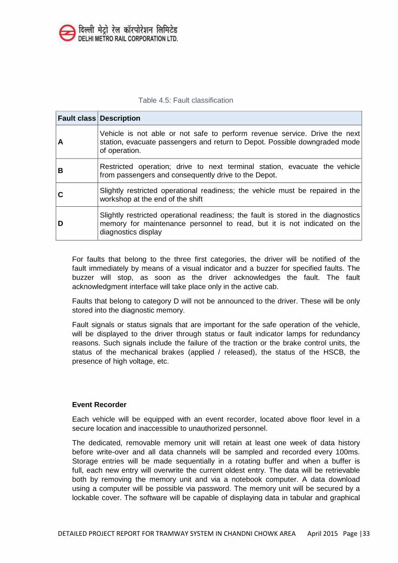
DETAILED PROJECT REPORT FOR TRAMWAY SYSTEM IN CHANDNI CHOWK AREA April 2015 Page |33
Table 4.5: Fault classification
Fault class Description
A Vehicle is not able or not safe to perform revenue service. Drive the next station, evacuate passengers and return to Depot. Possible downgraded mode of operation.
B Restricted operation; drive to next terminal station, evacuate the vehicle from passengers and consequently drive to the Depot.
C Slightly restricted operational readiness; the vehicle must be repaired in the workshop at the end of the shift
D Slightly restricted operational readiness; the fault is stored in the diagnostics memory for maintenance personnel to read, but it is not indicated on the diagnostics display
For faults that belong to the three first categories, the driver will be notified of the fault immediately by means of a visual indicator and a buzzer for specified faults. The buzzer will stop, as soon as the driver acknowledges the fault. The fault acknowledgment interface will take place only in the active cab.
Faults that belong to category D will not be announced to the driver. These will be only stored into the diagnostic memory.
Fault signals or status signals that are important for the safe operation of the vehicle, will be displayed to the driver through status or fault indicator lamps for redundancy reasons. Such signals include the failure of the traction or the brake control units, the status of the mechanical brakes (applied / released), the status of the HSCB, the presence of high voltage, etc.
Event Recorder
Each vehicle will be equipped with an event recorder, located above floor level in a secure location and inaccessible to unauthorized personnel.
The dedicated, removable memory unit will retain at least one week of data history before write-over and all data channels will be sampled and recorded every 100ms. Storage entries will be made sequentially in a rotating buffer and when a buffer is full, each new entry will overwrite the current oldest entry. The data will be retrievable both by removing the memory unit and via a notebook computer. A data download using a computer will be possible via password. The memory unit will be secured by a lockable cover. The software will be capable of displaying data in tabular and graphical
DETAILED PROJECT REPORT FOR TRAMWAY SYSTEM IN CHANDNI CHOWK AREA April 2015 Page |34
form (including colour) and it will readily interface with Microsoft Access, Excel and Word. Moreover, the suitable number of card readers will be provided in order to read and analyse the event recorder data.
Removal and replacement of the buffer memory and/or removal of the entire event recorder device will be possible in less than 5 minutes.
At a minimum, the system will be capable of providing the following facilities:
A printout of the state of all inputs over specified dates and times. Sample graphs of specified inputs versus time, distance and speed. Printouts of input states before and after a specified trigger event. Printouts of all occurrences of a specified input changing state. Printouts showing all occurrences of a specified sequence of events.
All data to be recorded will be submitted to Concerned Authority for approval. The following minimum data will be recorded.
Brake Cylinder Pressure Bypass Switch Status (all) Distance Travelled Since Event Door Status (closed, opened, isolated, etc) Operator’s Vigilance System Status Application of all Brake types (e.g. Electric, electrodynamic, safety, service, emergency brake,
etc.) Friction Brake Application Line Voltage / current Master Controller reference value Vehicle Direction (Forward, Reverse) Vehicle Speed Traction system status Auxiliary power supply system status Synchronization control with the vehicle master clock.
The event recorder will incorporate its own real time clock, generating year, month, day, hours, minutes and seconds. This clock will be constantly synchronized with the vehicle master clock. It will be accurate within ± 3s per month and will continue to run for not less than 30 days should external power be removed. It will correctly count leap years and the summer – winter time change.
Stored data will be retained for a minimum of 2 weeks with no external power required and the data will not be lost on the application of power.
The event recorder will not influence the state of circuits being monitored, nor any other circuits, even under fault conditions.
The event recorder will be designed and installed in the vehicles to protect critical data in incidents such as derailments, collision, flooding, fire, accidents, etc., to be readily available to support an accident investigation. The event recorder will be protected from the above conditions, whether by the design of the data storage units or insertion in a box meeting the requirements of British Railways Board Group Standard GO/OTS203. The protection will be IP67 per EN 60529.
DETAILED PROJECT REPORT FOR TRAMWAY SYSTEM IN CHANDNI CHOWK AREA April 2015 Page |35
The event recorder memory will also be protected against magnetic fields according to EN 50121-3-2.
The method of protecting the event recorder will be submitted for approved by AM.
Failure Modes and Effects Analysis to classify failures as follows:
Class A: The self-test detects and annunciates that the recorder fails to make a true and accurate recording of the inputs. Class B: The recorder fails to make a true and accurate recording of the inputs and this is not detected by the recorder.
The Mean Time between Failures for Class A will be no less than 100,000 operational hours per recorder. The Mean Time between Failures for Class B will be no less than 500,000 operational hours per recorder.
The event recorder will require the minimum of maintenance and will be no more frequent than once every 5 years.
Subsystems Control units
Whenever a fault or a defined operating state arises in a monitored part of the control and drive systems, this will be automatically stored in a diagnostics memory together with any other operating data. Each control unit will have its own diagnostics memory. The stored data will be accessible to the maintenance personnel and enable them to localise and eliminate the causes of any faults timely and accurately. All units will have an interface with the MVB Bus and the service ports will be easily accessible from inside the vehicle.
Any malfunction of the control units, or peripheral devices connected with the control units, will be signalled to the DDU.
The diagnostic system will run a self-test that excludes the case that the diagnostic system itself is faulty.
Wireless communication between the networks in the depot
Depot will be equipped with the appropriate wireless communication hardware and software to ensure wireless communication between vehicle/Depot; this hardware will be fully compatible with the respective on-board equipment.
The vehicle will be properly equipped, so that whenever it enters the Depot this equipment will wirelessly transmit to the Depot (Rolling Stock Workshop) various useful information (failures, systems operational status etc.) concerning all vital functions of the vehicle sub-systems (e.g. traction/braking, door system, HVAC system etc.).
Maintenance requirements
Self-diagnostic failure identification systems controlled by micro-processors will be utilized and all associated data will be collected either through a portable PC or wirelessly, as described above, by the Central Control Unit (TCMS) of each vehicle towards the central Computers to be installed in the Depot.
DETAILED PROJECT REPORT FOR TRAMWAY SYSTEM IN CHANDNI CHOWK AREA April 2015 Page |36
The technical characteristics on the selected subsystems and devices will fulfil the requirements pertaining to effective maintenance. All required signals and data concerning the status of the devices, any failures etc. will be visible and readily accessible. Readings to obtain data concerning error/failure will be taken as frequently as possible, enabling thus to determine accurately the correct failure curve.
The type and the accuracy of the data will fulfil the requirements concerning vehicle maintenance. The submitted hardware documentation will facilitate the Operation Company in troubleshooting any failures to individual devices, connection boards etc.
Under normal circumstances, all stored data will remain intact after a power failure for a period exceeding 48 hours.
All diagnostic data will include information related to the failure of any sub-system.
In time and as the vehicle fleet expands, the maintenance system will be capable to foresee possible future failures. Based on this data, the Operation Company will carry out an effective preventive maintenance, including the proper software tool for maintenance purposes.
DETAILED PROJECT REPORT FOR TRAMWAY SYSTEM IN CHANDNI CHOWK AREA April 2015 Page |1
CHAPTER-5
CIVIL ENGINEERING
Tramway track geometry and type of tracks are described below.
5.1 Track Gauge
The following assumptions have been adopted:
Track gauge will be Standard Gauge of 1,435 mm measured between the inner (gauge) sides on the heads of the rail at a distance of 14 mm below the top.
Gauge widening in curves is not normally applied. However, if gauge widening is applied in areas of tight curves and crossing works, the gauge widening will be compatible with the rail type and the wheel profile.
The entire corridor has two-way tracks.
5.2 Track Geometry
Description of route alignment
In the main commercial area from Swami Vivekanand Marg to Chandni Chowk road (0m to 1770m) and in Naya Bazaar Road (4000m to 4500m), is proposed at grade with 2m wide platform at stoppages on either side of the track. This option allows maximizing tramway operation speed and dissuades private vehicles traffic. The segregation will be achieved by means of a continuous 1 m high fences that will keep public away from the tracks except in the pedestrian crossings.
The section between chainage 420m to 500m (Khari Baoli Road near Fathehpuri majsid ) is the narrowest of the entire Corridor. The width of the carriageway is about 7 m. In that situation, the two-way track platform will completely occupy the current carriageway. Traffic in this section must be barred.
Concerned about the impact of the implantation of a tramway on the busy road of S.P Mukherji Marg, the Consultant was requested by DMRC to analyse an elevated section alongside S.P Mukherji Marg (chainage 2200m to 3900m). This arrangement would allow no reduction in the current carriageway. The rest of the alignment will remain at grade.
Between 2200m to 3900m corresponding to S.P Mukherji Marg, the recommended alignment would run along the median.
Stops 7 (Chainage, 2,470m), 8 (Chainage 2,950m) and 9 (Chainage 3,780m) will be elevated. A foot over bridge of 10m width has been proposed below the stoppages for allowing the public to cross road from one side to other.
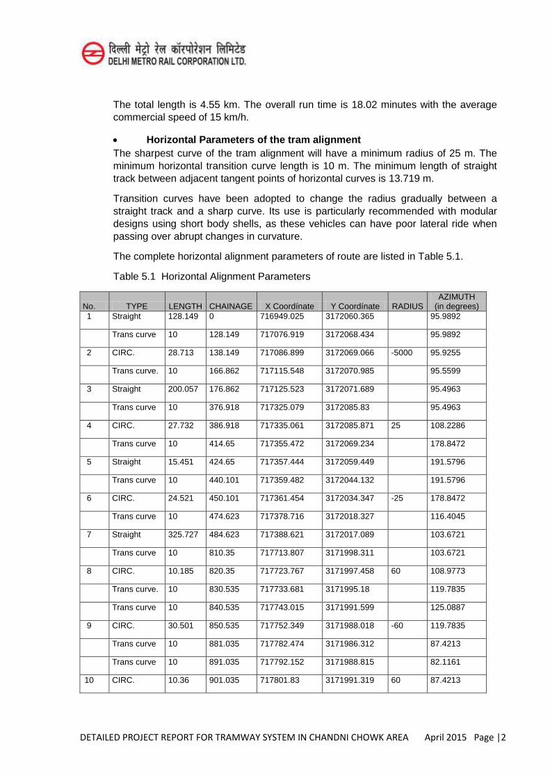
DETAILED PROJECT REPORT FOR TRAMWAY SYSTEM IN CHANDNI CHOWK AREA April 2015 Page |2
The total length is 4.55 km. The overall run time is 18.02 minutes with the average commercial speed of 15 km/h.
Horizontal Parameters of the tram alignment The sharpest curve of the tram alignment will have a minimum radius of 25 m. The minimum horizontal transition curve length is 10 m. The minimum length of straight track between adjacent tangent points of horizontal curves is 13.719 m.
Transition curves have been adopted to change the radius gradually between a straight track and a sharp curve. Its use is particularly recommended with modular designs using short body shells, as these vehicles can have poor lateral ride when passing over abrupt changes in curvature.
The complete horizontal alignment parameters of route are listed in Table 5.1.
Table 5.1 Horizontal Alignment Parameters
No. TYPE LENGTH CHAINAGE X Coordínate Y Coordínate RADIUS AZIMUTH
(in degrees) 1 Straight 128.149 0 716949.025 3172060.365 95.9892
Trans curve 10 128.149 717076.919 3172068.434 95.9892
2 CIRC. 28.713 138.149 717086.899 3172069.066 -5000 95.9255
Trans curve. 10 166.862 717115.548 3172070.985 95.5599
3 Straight 200.057 176.862 717125.523 3172071.689 95.4963
Trans curve 10 376.918 717325.079 3172085.83 95.4963
4 CIRC. 27.732 386.918 717335.061 3172085.871 25 108.2286
Trans curve 10 414.65 717355.472 3172069.234 178.8472
5 Straight 15.451 424.65 717357.444 3172059.449 191.5796
Trans curve 10 440.101 717359.482 3172044.132 191.5796
6 CIRC. 24.521 450.101 717361.454 3172034.347 -25 178.8472
Trans curve 10 474.623 717378.716 3172018.327 116.4045
7 Straight 325.727 484.623 717388.621 3172017.089 103.6721
Trans curve 10 810.35 717713.807 3171998.311 103.6721
8 CIRC. 10.185 820.35 717723.767 3171997.458 60 108.9773
Trans curve. 10 830.535 717733.681 3171995.18 119.7835
Trans curve 10 840.535 717743.015 3171991.599 125.0887
9 CIRC. 30.501 850.535 717752.349 3171988.018 -60 119.7835
Trans curve 10 881.035 717782.474 3171986.312 87.4213
Trans curve 10 891.035 717792.152 3171988.815 82.1161
10 CIRC. 10.36 901.035 717801.83 3171991.319 60 87.4213
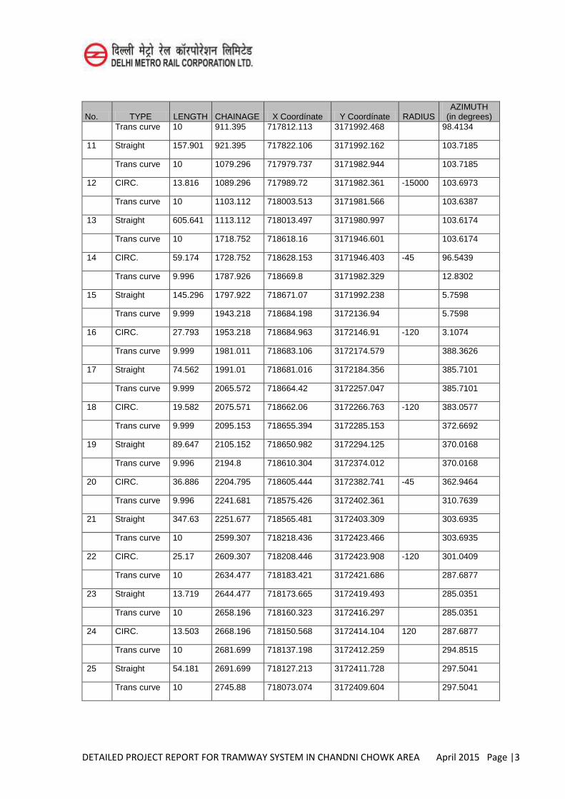
DETAILED PROJECT REPORT FOR TRAMWAY SYSTEM IN CHANDNI CHOWK AREA April 2015 Page |3
No. TYPE LENGTH CHAINAGE X Coordínate Y Coordínate RADIUS AZIMUTH
(in degrees) Trans curve 10 911.395 717812.113 3171992.468 98.4134
11 Straight 157.901 921.395 717822.106 3171992.162 103.7185
Trans curve 10 1079.296 717979.737 3171982.944 103.7185
12 CIRC. 13.816 1089.296 717989.72 3171982.361 -15000 103.6973
Trans curve 10 1103.112 718003.513 3171981.566 103.6387
13 Straight 605.641 1113.112 718013.497 3171980.997 103.6174
Trans curve 10 1718.752 718618.16 3171946.601 103.6174
14 CIRC. 59.174 1728.752 718628.153 3171946.403 -45 96.5439
Trans curve 9.996 1787.926 718669.8 3171982.329 12.8302
15 Straight 145.296 1797.922 718671.07 3171992.238 5.7598
Trans curve 9.999 1943.218 718684.198 3172136.94 5.7598
16 CIRC. 27.793 1953.218 718684.963 3172146.91 -120 3.1074
Trans curve 9.999 1981.011 718683.106 3172174.579 388.3626
17 Straight 74.562 1991.01 718681.016 3172184.356 385.7101
Trans curve 9.999 2065.572 718664.42 3172257.047 385.7101
18 CIRC. 19.582 2075.571 718662.06 3172266.763 -120 383.0577
Trans curve 9.999 2095.153 718655.394 3172285.153 372.6692
19 Straight 89.647 2105.152 718650.982 3172294.125 370.0168
Trans curve 9.996 2194.8 718610.304 3172374.012 370.0168
20 CIRC. 36.886 2204.795 718605.444 3172382.741 -45 362.9464
Trans curve 9.996 2241.681 718575.426 3172402.361 310.7639
21 Straight 347.63 2251.677 718565.481 3172403.309 303.6935
Trans curve 10 2599.307 718218.436 3172423.466 303.6935
22 CIRC. 25.17 2609.307 718208.446 3172423.908 -120 301.0409
Trans curve 10 2634.477 718183.421 3172421.686 287.6877
23 Straight 13.719 2644.477 718173.665 3172419.493 285.0351
Trans curve 10 2658.196 718160.323 3172416.297 285.0351
24 CIRC. 13.503 2668.196 718150.568 3172414.104 120 287.6877
Trans curve 10 2681.699 718137.198 3172412.259 294.8515
25 Straight 54.181 2691.699 718127.213 3172411.728 297.5041
Trans curve 10 2745.88 718073.074 3172409.604 297.5041
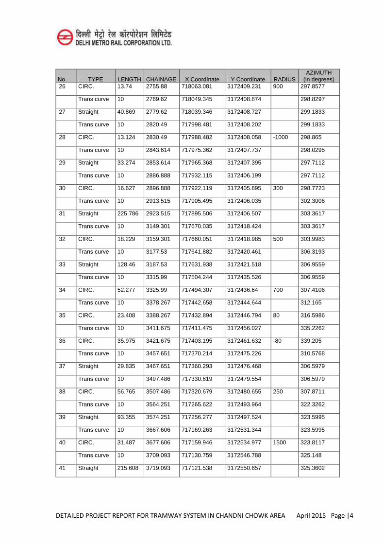
DETAILED PROJECT REPORT FOR TRAMWAY SYSTEM IN CHANDNI CHOWK AREA April 2015 Page |4
No. TYPE LENGTH CHAINAGE X Coordínate Y Coordínate RADIUS AZIMUTH
(in degrees) 26 CIRC. 13.74 2755.88 718063.081 3172409.231 900 297.8577
Trans curve 10 2769.62 718049.345 3172408.874 298.8297
27 Straight 40.869 2779.62 718039.346 3172408.727 299.1833
Trans curve 10 2820.49 717998.481 3172408.202 299.1833
28 CIRC. 13.124 2830.49 717988.482 3172408.058 -1000 298.865
Trans curve 10 2843.614 717975.362 3172407.737 298.0295
29 Straight 33.274 2853.614 717965.368 3172407.395 297.7112
Trans curve 10 2886.888 717932.115 3172406.199 297.7112
30 CIRC. 16.627 2896.888 717922.119 3172405.895 300 298.7723
Trans curve 10 2913.515 717905.495 3172406.035 302.3006
31 Straight 225.786 2923.515 717895.506 3172406.507 303.3617
Trans curve 10 3149.301 717670.035 3172418.424 303.3617
32 CIRC. 18.229 3159.301 717660.051 3172418.985 500 303.9983
Trans curve 10 3177.53 717641.882 3172420.461 306.3193
33 Straight 128.46 3187.53 717631.938 3172421.518 306.9559
Trans curve 10 3315.99 717504.244 3172435.526 306.9559
34 CIRC. 52.277 3325.99 717494.307 3172436.64 700 307.4106
Trans curve 10 3378.267 717442.658 3172444.644 312.165
35 CIRC. 23.408 3388.267 717432.894 3172446.794 80 316.5986
Trans curve 10 3411.675 717411.475 3172456.027 335.2262
36 CIRC. 35.975 3421.675 717403.195 3172461.632 -80 339.205
Trans curve 10 3457.651 717370.214 3172475.226 310.5768
37 Straight 29.835 3467.651 717360.293 3172476.468 306.5979
Trans curve 10 3497.486 717330.619 3172479.554 306.5979
38 CIRC. 56.765 3507.486 717320.679 3172480.655 250 307.8711
Trans curve 10 3564.251 717265.622 3172493.964 322.3262
39 Straight 93.355 3574.251 717256.277 3172497.524 323.5995
Trans curve 10 3667.606 717169.263 3172531.344 323.5995
40 CIRC. 31.487 3677.606 717159.946 3172534.977 1500 323.8117
Trans curve 10 3709.093 717130.759 3172546.788 325.148
41 Straight 215.608 3719.093 717121.538 3172550.657 325.3602
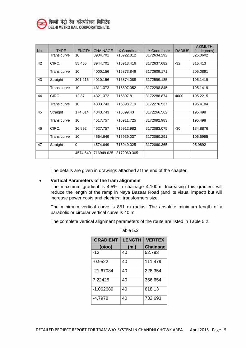
DETAILED PROJECT REPORT FOR TRAMWAY SYSTEM IN CHANDNI CHOWK AREA April 2015 Page |5
No. TYPE LENGTH CHAINAGE X Coordínate Y Coordínate RADIUS AZIMUTH
(in degrees) Trans curve 10 3934.701 716922.812 3172634.292 325.3602
42 CIRC. 55.455 3944.701 716913.416 3172637.682 -32 315.413
Trans curve 10 4000.156 716873.846 3172609.171 205.0891
43 Straight 301.216 4010.156 716874.088 3172599.185 195.1419
Trans curve 10 4311.372 716897.052 3172298.845 195.1419
44 CIRC. 12.37 4321.372 716897.81 3172288.874 4000 195.2215
Trans curve 10 4333.743 716898.719 3172276.537 195.4184
45 Straight 174.014 4343.743 716899.43 3172266.562 195.498
Trans curve 10 4517.757 716911.725 3172092.983 195.498
46 CIRC. 36.892 4527.757 716912.983 3172083.075 -30 184.8876
Trans curve 10 4564.649 716939.037 3172060.291 106.5995
47 Straight 0 4574.649 716949.025 3172060.365 95.9892
4574.649 716949.025 3172060.365
The details are given in drawings attached at the end of the chapter.
Vertical Parameters of the tram alignment The maximum gradient is 4.5% in chainage 4,100m. Increasing this gradient will reduce the length of the ramp in Naya Bazaar Road (and its visual impact) but will increase power costs and electrical transformers size.
The minimum vertical curve is 851 m radius. The absolute minimum length of a parabolic or circular vertical curve is 40 m.
The complete vertical alignment parameters of the route are listed in Table 5.2.
Table 5.2
GRADIENT LENGTH VERTEX
(o/oo) (m.) Chainage -12 40 52.793
-0.9522 40 111.479
-21.67084 40 228.354
7.22425 40 356.654
-1.062689 40 618.13
-4.7978 40 732.693
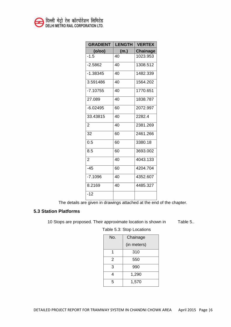
DETAILED PROJECT REPORT FOR TRAMWAY SYSTEM IN CHANDNI CHOWK AREA April 2015 Page |6
GRADIENT LENGTH VERTEX
(o/oo) (m.) Chainage -1.5 40 1023.953
-2.5862 40 1308.512
-1.38345 40 1482.339
3.591486 40 1564.202
-7.10755 40 1770.651
27.089 40 1838.787
-6.02495 60 2072.997
33.43815 40 2282.4
2 40 2381.269
32 60 2461.266
0.5 60 3380.18
8.5 60 3693.002
2 40 4043.133
-45 60 4204.704
-7.1096 40 4352.607
8.2169 40 4485.327
-12
The details are given in drawings attached at the end of the chapter.
5.3 Station Platforms
10 Stops are proposed. Their approximate location is shown in Table 5..
Table 5.3: Stop Locations
No. Chainage
(in meters)
1 310
2 550
3 990
4 1,290
5 1,570
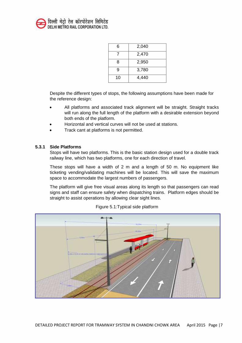
DETAILED PROJECT REPORT FOR TRAMWAY SYSTEM IN CHANDNI CHOWK AREA April 2015 Page |7
6 2,040
7 2,470
8 2,950
9 3,780
10 4,440
Despite the different types of stops, the following assumptions have been made for the reference design:
All platforms and associated track alignment will be straight. Straight tracks will run along the full length of the platform with a desirable extension beyond both ends of the platform.
Horizontal and vertical curves will not be used at stations. Track cant at platforms is not permitted.
5.3.1 Side Platforms Stops will have two platforms. This is the basic station design used for a double track railway line, which has two platforms, one for each direction of travel.
These stops will have a width of 2 m and a length of 50 m. No equipment like ticketing vending/validating machines will be located. This will save the maximum space to accommodate the largest numbers of passengers.
The platform will give free visual areas along its length so that passengers can read signs and staff can ensure safety when dispatching trains. Platform edges should be straight to assist operations by allowing clear sight lines.
Figure 5.1:Typical side platform
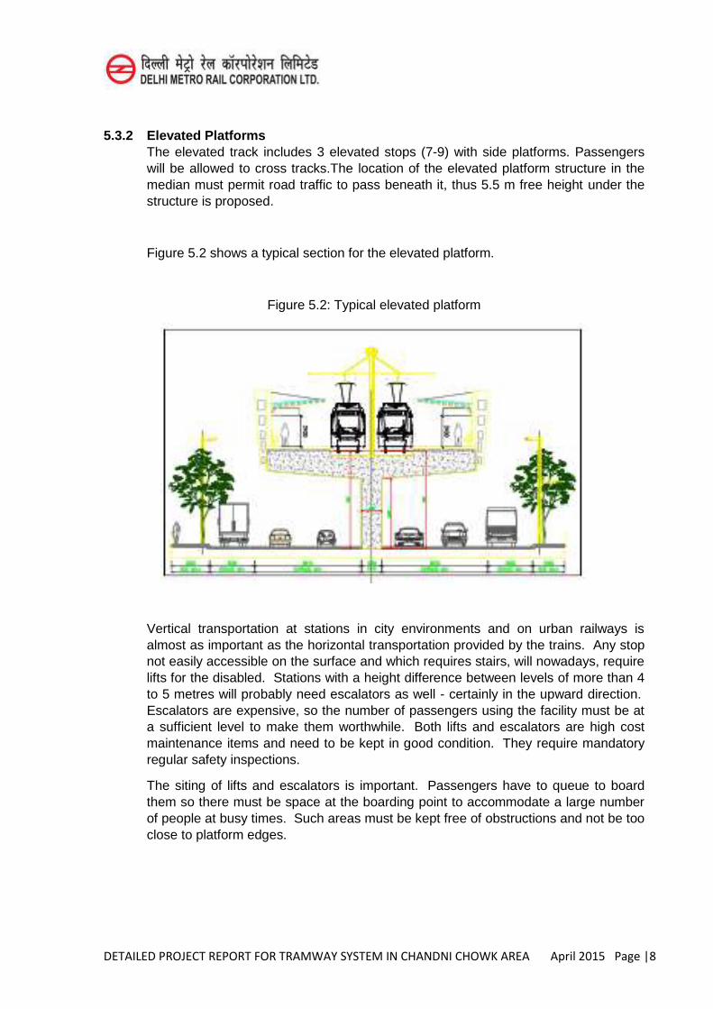
DETAILED PROJECT REPORT FOR TRAMWAY SYSTEM IN CHANDNI CHOWK AREA April 2015 Page |8
5.3.2 Elevated Platforms The elevated track includes 3 elevated stops (7-9) with side platforms. Passengers will be allowed to cross tracks.The location of the elevated platform structure in the median must permit road traffic to pass beneath it, thus 5.5 m free height under the structure is proposed.
Figure 5.2 shows a typical section for the elevated platform.
Figure 5.2: Typical elevated platform
Vertical transportation at stations in city environments and on urban railways is almost as important as the horizontal transportation provided by the trains. Any stop not easily accessible on the surface and which requires stairs, will nowadays, require lifts for the disabled. Stations with a height difference between levels of more than 4 to 5 metres will probably need escalators as well - certainly in the upward direction. Escalators are expensive, so the number of passengers using the facility must be at a sufficient level to make them worthwhile. Both lifts and escalators are high cost maintenance items and need to be kept in good condition. They require mandatory regular safety inspections.
The siting of lifts and escalators is important. Passengers have to queue to board them so there must be space at the boarding point to accommodate a large number of people at busy times. Such areas must be kept free of obstructions and not be too close to platform edges.
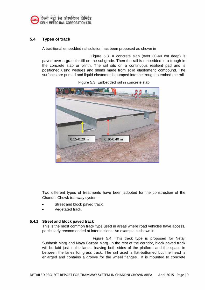
DETAILED PROJECT REPORT FOR TRAMWAY SYSTEM IN CHANDNI CHOWK AREA April 2015 Page |9
5.4 Types of track
A traditional embedded rail solution has been proposed as shown in
Figure 5.3. A concrete slab (over 30-40 cm deep) is paved over a granular fill on the subgrade. Then the rail is embedded in a trough in the concrete slab or plinth. The rail sits on a continuous resilient pad and is positioned using wedges and shims made from solid elastomeric compound. The surfaces are primed and liquid elastomer is pumped into the trough to embed the rail.
Figure 5.3: Embedded rail in concrete slab
Two different types of treatments have been adopted for the construction of the Chandni Chowk tramway system:
Street and block paved track. Vegetated track.
5.4.1 Street and block paved track This is the most common track type used in areas where road vehicles have access, particularly recommended at intersections. An example is shown in
Figure 5.4. This track type is proposed for Netaji Subhash Marg and Naya Bazaar Marg. In the rest of the corridor, block paved track will be laid just in the lanes, leaving both sides of the platform and the space in between the lanes for grass track. The rail used is flat-bottomed but the head is enlarged and contains a groove for the wheel flanges. It is mounted to concrete
0.30-0.40 m 0.15-0.20 m
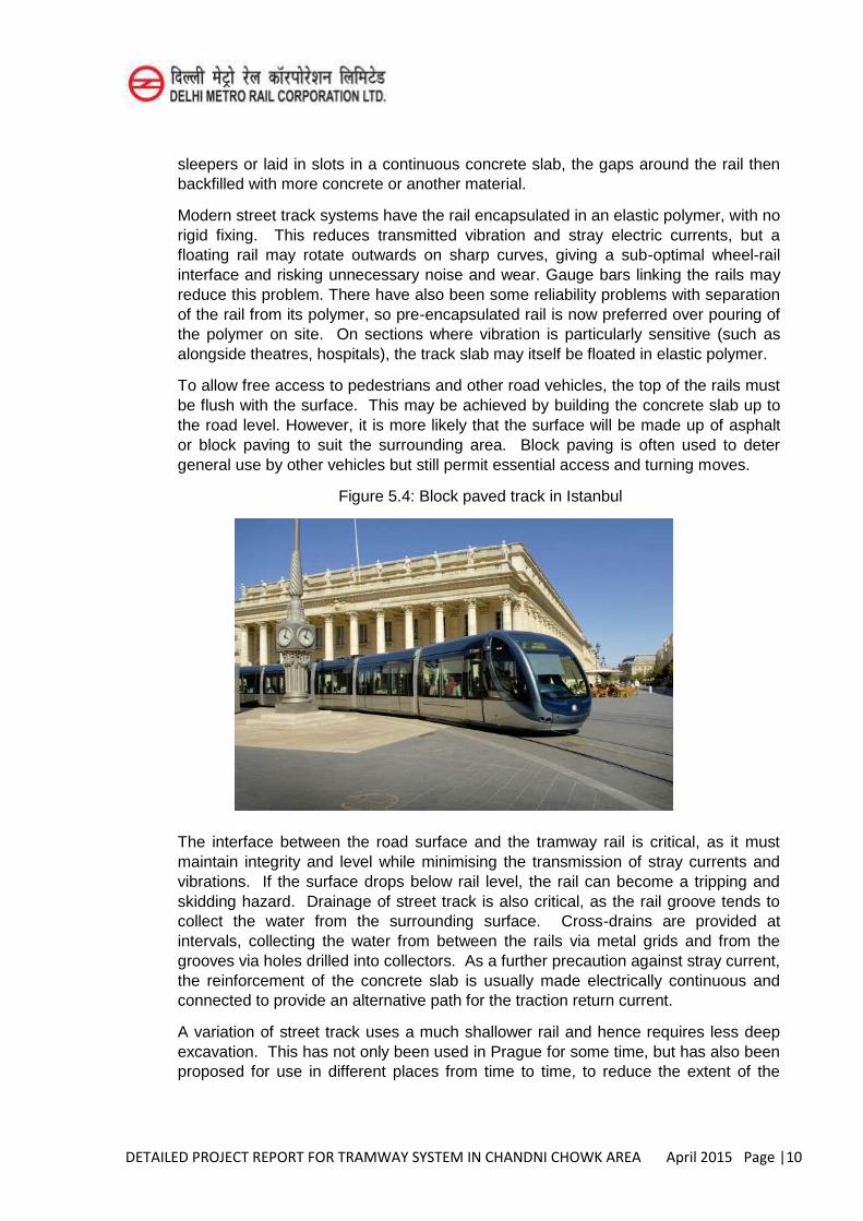
DETAILED PROJECT REPORT FOR TRAMWAY SYSTEM IN CHANDNI CHOWK AREA April 2015 Page |10
sleepers or laid in slots in a continuous concrete slab, the gaps around the rail then backfilled with more concrete or another material.
Modern street track systems have the rail encapsulated in an elastic polymer, with no rigid fixing. This reduces transmitted vibration and stray electric currents, but a floating rail may rotate outwards on sharp curves, giving a sub-optimal wheel-rail interface and risking unnecessary noise and wear. Gauge bars linking the rails may reduce this problem. There have also been some reliability problems with separation of the rail from its polymer, so pre-encapsulated rail is now preferred over pouring of the polymer on site. On sections where vibration is particularly sensitive (such as alongside theatres, hospitals), the track slab may itself be floated in elastic polymer.
To allow free access to pedestrians and other road vehicles, the top of the rails must be flush with the surface. This may be achieved by building the concrete slab up to the road level. However, it is more likely that the surface will be made up of asphalt or block paving to suit the surrounding area. Block paving is often used to deter general use by other vehicles but still permit essential access and turning moves.
Figure 5.4: Block paved track in Istanbul
The interface between the road surface and the tramway rail is critical, as it must maintain integrity and level while minimising the transmission of stray currents and vibrations. If the surface drops below rail level, the rail can become a tripping and skidding hazard. Drainage of street track is also critical, as the rail groove tends to collect the water from the surrounding surface. Cross-drains are provided at intervals, collecting the water from between the rails via metal grids and from the grooves via holes drilled into collectors. As a further precaution against stray current, the reinforcement of the concrete slab is usually made electrically continuous and connected to provide an alternative path for the traction return current.
A variation of street track uses a much shallower rail and hence requires less deep excavation. This has not only been used in Prague for some time, but has also been proposed for use in different places from time to time, to reduce the extent of the
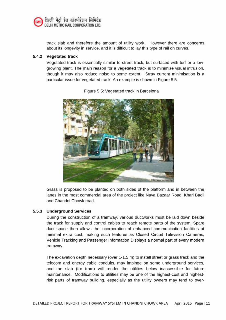
DETAILED PROJECT REPORT FOR TRAMWAY SYSTEM IN CHANDNI CHOWK AREA April 2015 Page |11
track slab and therefore the amount of utility work. However there are concerns about its longevity in service, and it is difficult to lay this type of rail on curves.
5.4.2 Vegetated track Vegetated track is essentially similar to street track, but surfaced with turf or a low-
growing plant. The main reason for a vegetated track is to minimise visual intrusion, though it may also reduce noise to some extent. Stray current minimisation is a particular issue for vegetated track. An example is shown in Figure 5.5.
Figure 5.5: Vegetated track in Barcelona
Grass is proposed to be planted on both sides of the platform and in between the lanes in the most commercial area of the project like Naya Bazaar Road, Khari Baoli and Chandni Chowk road.
5.5.3 Underground Services During the construction of a tramway, various ductworks must be laid down beside
the track for supply and control cables to reach remote parts of the system. Spare duct space then allows the incorporation of enhanced communication facilities at minimal extra cost; making such features as Closed Circuit Television Cameras, Vehicle Tracking and Passenger Information Displays a normal part of every modern tramway.
The excavation depth necessary (over 1-1.5 m) to install street or grass track and the telecom and energy cable conduits, may impinge on some underground services, and the slab (for tram) will render the utilities below inaccessible for future maintenance. Modifications to utilities may be one of the highest-cost and highest-risk parts of tramway building, especially as the utility owners may tend to over-
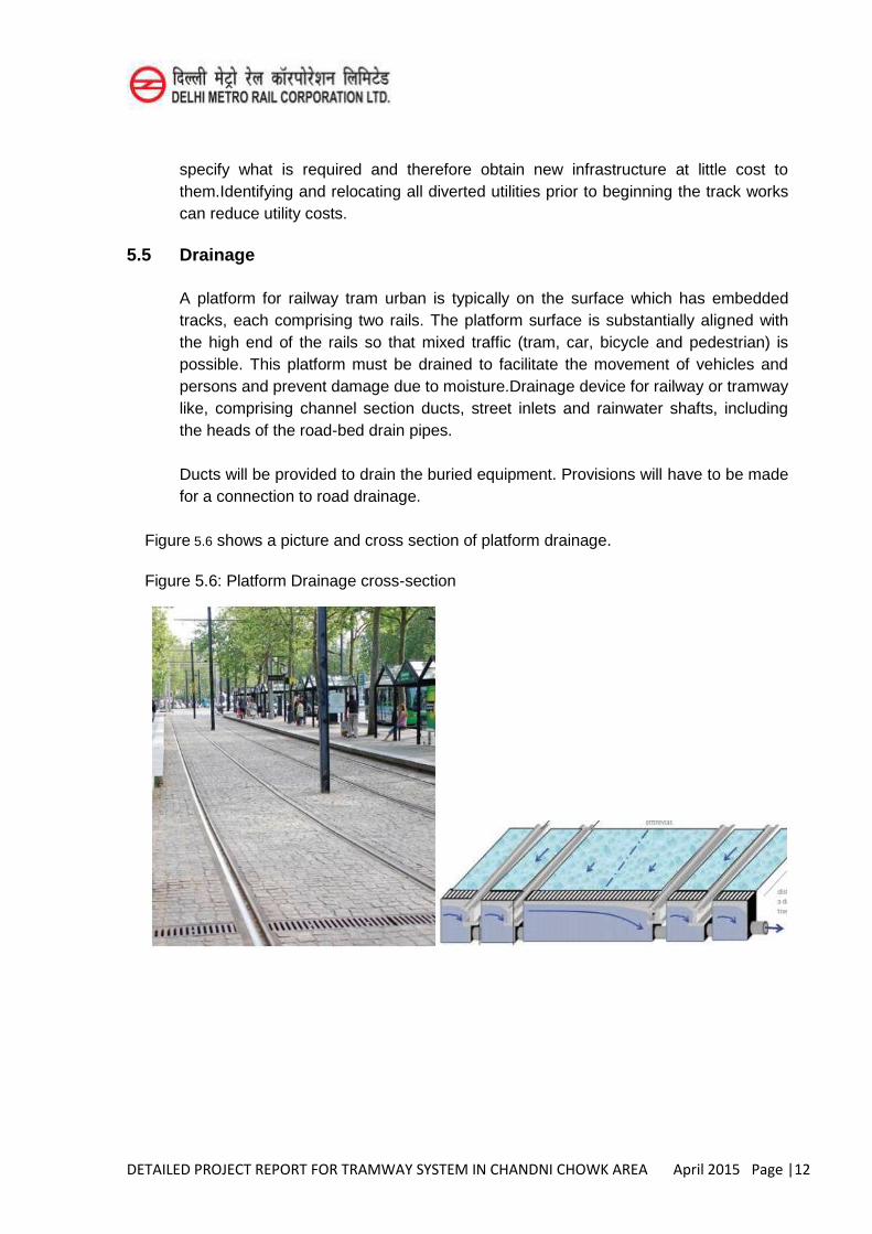
DETAILED PROJECT REPORT FOR TRAMWAY SYSTEM IN CHANDNI CHOWK AREA April 2015 Page |12
specify what is required and therefore obtain new infrastructure at little cost to them.Identifying and relocating all diverted utilities prior to beginning the track works can reduce utility costs.
5.5 Drainage
A platform for railway tram urban is typically on the surface which has embedded tracks, each comprising two rails. The platform surface is substantially aligned with the high end of the rails so that mixed traffic (tram, car, bicycle and pedestrian) is possible. This platform must be drained to facilitate the movement of vehicles and persons and prevent damage due to moisture.Drainage device for railway or tramway like, comprising channel section ducts, street inlets and rainwater shafts, including the heads of the road-bed drain pipes.
Ducts will be provided to drain the buried equipment. Provisions will have to be made for a connection to road drainage.
Figure 5.6 shows a picture and cross section of platform drainage.
Figure 5.6: Platform Drainage cross-section
DETAILED PROJECT REPORT FOR TRAMWAY SYSTEM IN CHANDNI CHOWK AREA April 2015 Page|1
CHAPTER-6
TRAM OPERATION PLAN
This chapter describes the operation plan of Chandni Chowk tramway system indicating the headway depends on time interval, the calculation of travel time, the calculation of the necessary fleet and finally the production of km and commercial hours per year.Public Transportation is a lifeline to many, especially in crisis. Across the world, budgets are slashed, services are pruned, routes are disappearing, riders get stranded, transit workers are aging and fares are increasing. A closer view of this broad and diverse environment reveals its inherent complexity. The objective is to optimize the operation with the least environment impacts while catering to rider expectations within limited resources.
The objective of this document is to provide the facilities to passengers to meet their and other stakeholders’ needs in a safe, secure, comfortable, reliable, efficient, punctual and
clean manner. Appropriate standards, codes and regulations will be followed during the operating phase.
6.1 Operation Philosophy
The underlying operation philosophy is to make the Tram System more attractive and economical, the main features being:
Selecting the most optimum frequency of Tram services to meet sectional capacity requirement during peak hours on most of the sections.
Economical & optimum tram service frequency not only during peak period, but also during off-peak period.
Multi-tasking of train operation and maintenance staff. An efficient Incident Management and Response Plan.
6.2 Stations The line is a two-way track that has a length of 4.5 km (Approx.) including 10 stations- as shown in Table 6.1. The names of the stations will be decided in consultation with GNCTD.
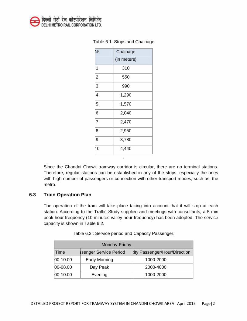
DETAILED PROJECT REPORT FOR TRAMWAY SYSTEM IN CHANDNI CHOWK AREA April 2015 Page|2
Table 6.1: Stops and Chainage
Nº Chainage
(in meters)
1 310
2 550
3 990
4 1,290
5 1,570
6 2,040
7 2,470
8 2,950
9 3,780
10 4,440
.
Since the Chandni Chowk tramway corridor is circular, there are no terminal stations. Therefore, regular stations can be established in any of the stops, especially the ones with high number of passengers or connection with other transport modes, such as, the metro.
6.3 Train Operation Plan
The operation of the tram will take place taking into account that it will stop at each station. According to the Traffic Study supplied and meetings with consultants, a 5 min peak hour frequency (10 minutes valley hour frequency) has been adopted. The service capacity is shown in Table 6.2.
Table 6.2 : Service period and Capacity Passenger.
Monday-Friday
Time Passenger Service Period Capacity Passenger/Hour/Direction
08.00-10.00 Early Morning 1000-2000
10.00-08.00 Day Peak 2000-4000
08.00-10.00 Evening 1000-2000
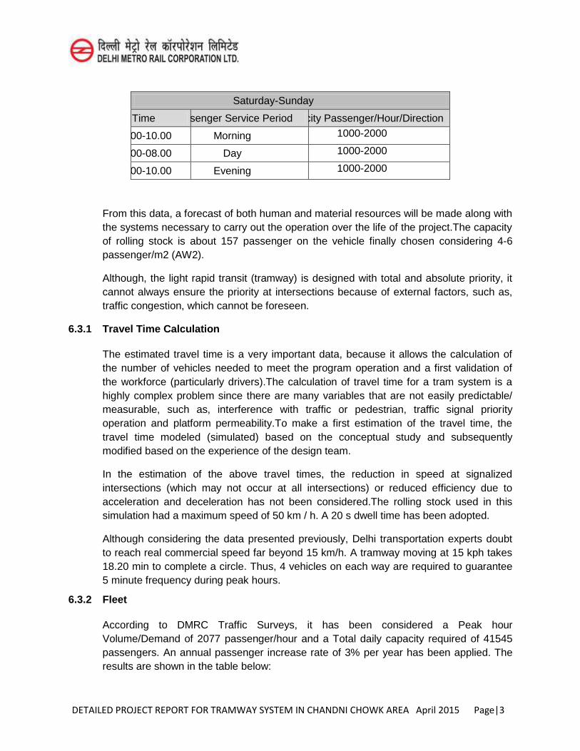
DETAILED PROJECT REPORT FOR TRAMWAY SYSTEM IN CHANDNI CHOWK AREA April 2015 Page|3
Saturday-Sunday
Time Passenger Service Period Capacity Passenger/Hour/Direction
08.00-10.00 Morning 1000-2000
10.00-08.00 Day 1000-2000
08.00-10.00 Evening 1000-2000
From this data, a forecast of both human and material resources will be made along with the systems necessary to carry out the operation over the life of the project.The capacity of rolling stock is about 157 passenger on the vehicle finally chosen considering 4-6 passenger/m2 (AW2).
Although, the light rapid transit (tramway) is designed with total and absolute priority, it cannot always ensure the priority at intersections because of external factors, such as, traffic congestion, which cannot be foreseen.
6.3.1 Travel Time Calculation
The estimated travel time is a very important data, because it allows the calculation of the number of vehicles needed to meet the program operation and a first validation of the workforce (particularly drivers).The calculation of travel time for a tram system is a highly complex problem since there are many variables that are not easily predictable/ measurable, such as, interference with traffic or pedestrian, traffic signal priority operation and platform permeability.To make a first estimation of the travel time, the travel time modeled (simulated) based on the conceptual study and subsequently modified based on the experience of the design team.
In the estimation of the above travel times, the reduction in speed at signalized intersections (which may not occur at all intersections) or reduced efficiency due to acceleration and deceleration has not been considered.The rolling stock used in this simulation had a maximum speed of 50 km / h. A 20 s dwell time has been adopted.
Although considering the data presented previously, Delhi transportation experts doubt to reach real commercial speed far beyond 15 km/h. A tramway moving at 15 kph takes 18.20 min to complete a circle. Thus, 4 vehicles on each way are required to guarantee 5 minute frequency during peak hours.
6.3.2 Fleet
According to DMRC Traffic Surveys, it has been considered a Peak hour Volume/Demand of 2077 passenger/hour and a Total daily capacity required of 41545 passengers. An annual passenger increase rate of 3% per year has been applied. The results are shown in the table below:
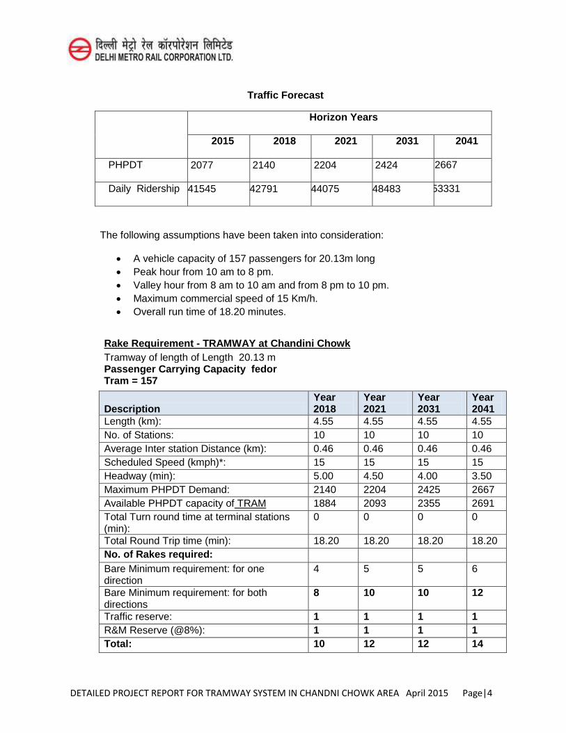
DETAILED PROJECT REPORT FOR TRAMWAY SYSTEM IN CHANDNI CHOWK AREA April 2015 Page|4
Traffic Forecast
Horizon Years
2015 2018 2021 2031 2041
PHPDT 2077 2140 2204 2424 2667
Daily Ridership 41545 42791 44075 48483 53331
The following assumptions have been taken into consideration:
A vehicle capacity of 157 passengers for 20.13m long Peak hour from 10 am to 8 pm. Valley hour from 8 am to 10 am and from 8 pm to 10 pm. Maximum commercial speed of 15 Km/h. Overall run time of 18.20 minutes.
Rake Requirement - TRAMWAY at Chandini Chowk Tramway of length of Length 20.13 m
Passenger Carrying Capacity fedor Tram = 157
Description Year 2018
Year 2021
Year 2031
Year 2041
Length (km): 4.55 4.55 4.55 4.55 No. of Stations: 10 10 10 10 Average Inter station Distance (km): 0.46 0.46 0.46 0.46 Scheduled Speed (kmph)*: 15 15 15 15 Headway (min): 5.00 4.50 4.00 3.50 Maximum PHPDT Demand: 2140 2204 2425 2667 Available PHPDT capacity of TRAM 1884 2093 2355 2691 Total Turn round time at terminal stations (min):
0 0 0 0
Total Round Trip time (min): 18.20 18.20 18.20 18.20 No. of Rakes required: Bare Minimum requirement: for one direction
4 5 5 6
Bare Minimum requirement: for both directions
8 10 10 12
Traffic reserve: 1 1 1 1 R&M Reserve (@8%): 1 1 1 1 Total: 10 12 12 14
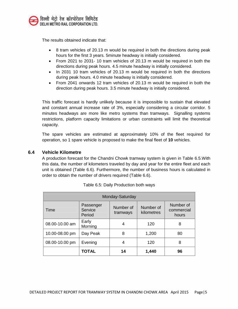
DETAILED PROJECT REPORT FOR TRAMWAY SYSTEM IN CHANDNI CHOWK AREA April 2015 Page|5
The results obtained indicate that:
8 tram vehicles of 20.13 m would be required in both the directions during peak hours for the first 3 years. 5minute headway is initially considered.
From 2021 to 2031- 10 tram vehicles of 20.13 m would be required in both the directions during peak hours. 4.5 minute headway is initially considered.
In 2031 10 tram vehicles of 20.13 m would be required in both the directions during peak hours. 4.0 minute headway is initially considered.
From 2041 onwards 12 tram vehicles of 20.13 m would be required in both the direction during peak hours. 3.5 minute headway is initially considered.
This traffic forecast is hardly unlikely because it is impossible to sustain that elevated and constant annual increase rate of 3%, especially considering a circular corridor. 5 minutes headways are more like metro systems than tramways. Signalling systems restrictions, platform capacity limitations or urban constraints will limit the theoretical capacity.
The spare vehicles are estimated at approximately 10% of the fleet required for operation, so 1 spare vehicle is proposed to make the final fleet of 10 vehicles.
6.4 Vehicle Kilometre A production forecast for the Chandni Chowk tramway system is given in Table 6.5.With this data, the number of kilometers traveled by day and year for the entire fleet and each unit is obtained (Table 6.6). Furthermore, the number of business hours is calculated in order to obtain the number of drivers required (Table 6.6).
Table 6.5: Daily Production both ways
Monday-Saturday
Time Passenger Service Period
Number of tramways
Number of kilometres
Number of commercial
hours
08.00-10.00 am Early Morning 4 120 8
10.00-08.00 pm Day Peak 8 1,200 80
08.00-10.00 pm Evening 4 120 8
TOTAL 14 1,440 96
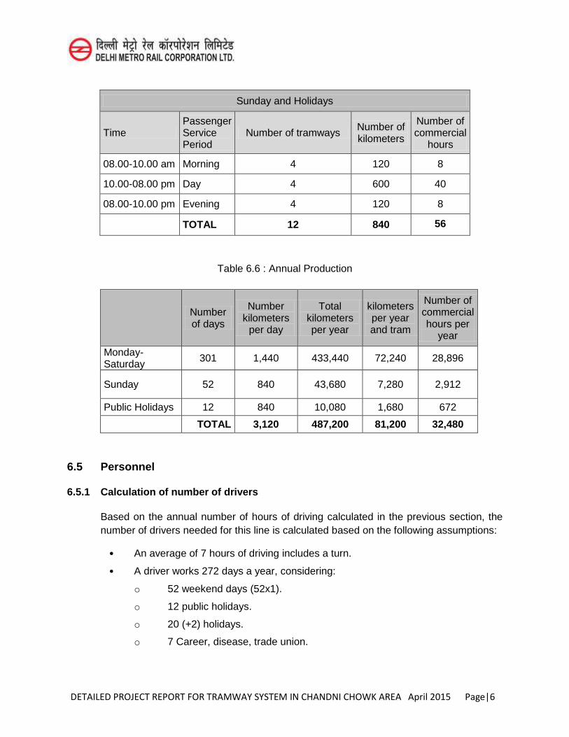
DETAILED PROJECT REPORT FOR TRAMWAY SYSTEM IN CHANDNI CHOWK AREA April 2015 Page|6
Sunday and Holidays
Time Passenger Service Period
Number of tramways Number of kilometers
Number of commercial
hours
08.00-10.00 am Morning 4 120 8
10.00-08.00 pm Day 4 600 40
08.00-10.00 pm Evening 4 120 8
TOTAL 12 840 56
Table 6.6 : Annual Production
Number of days
Number kilometers
per day
Total kilometers per year
kilometers per year and tram
Number of commercial hours per
year
Monday-Saturday 301 1,440 433,440 72,240 28,896
Sunday 52 840 43,680 7,280 2,912
Public Holidays 12 840 10,080 1,680 672
TOTAL 3,120 487,200 81,200 32,480
6.5 Personnel
6.5.1 Calculation of number of drivers
Based on the annual number of hours of driving calculated in the previous section, the number of drivers needed for this line is calculated based on the following assumptions:
• An average of 7 hours of driving includes a turn.
• A driver works 272 days a year, considering:
o 52 weekend days (52x1).
o 12 public holidays.
o 20 (+2) holidays.
o 7 Career, disease, trade union.
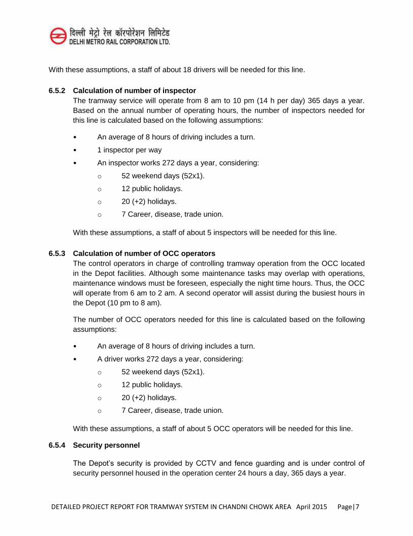
DETAILED PROJECT REPORT FOR TRAMWAY SYSTEM IN CHANDNI CHOWK AREA April 2015 Page|7
With these assumptions, a staff of about 18 drivers will be needed for this line.
6.5.2 Calculation of number of inspector The tramway service will operate from 8 am to 10 pm (14 h per day) 365 days a year. Based on the annual number of operating hours, the number of inspectors needed for this line is calculated based on the following assumptions:
• An average of 8 hours of driving includes a turn.
• 1 inspector per way
• An inspector works 272 days a year, considering:
o 52 weekend days (52x1).
o 12 public holidays.
o 20 (+2) holidays.
o 7 Career, disease, trade union.
With these assumptions, a staff of about 5 inspectors will be needed for this line.
6.5.3 Calculation of number of OCC operators The control operators in charge of controlling tramway operation from the OCC located in the Depot facilities. Although some maintenance tasks may overlap with operations, maintenance windows must be foreseen, especially the night time hours. Thus, the OCC will operate from 6 am to 2 am. A second operator will assist during the busiest hours in the Depot (10 pm to 8 am).
The number of OCC operators needed for this line is calculated based on the following assumptions:
• An average of 8 hours of driving includes a turn.
• A driver works 272 days a year, considering:
o 52 weekend days (52x1).
o 12 public holidays.
o 20 (+2) holidays.
o 7 Career, disease, trade union.
With these assumptions, a staff of about 5 OCC operators will be needed for this line.
6.5.4 Security personnel
The Depot’s security is provided by CCTV and fence guarding and is under control of
security personnel housed in the operation center 24 hours a day, 365 days a year.
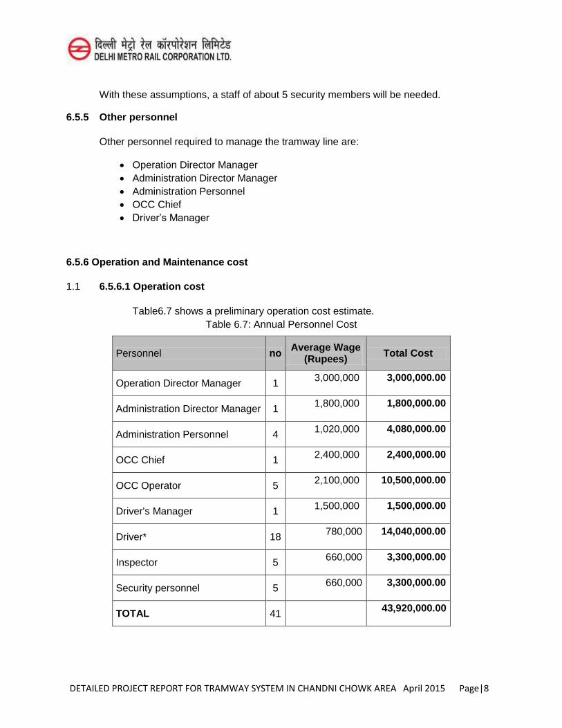
DETAILED PROJECT REPORT FOR TRAMWAY SYSTEM IN CHANDNI CHOWK AREA April 2015 Page|8
With these assumptions, a staff of about 5 security members will be needed.
6.5.5 Other personnel
Other personnel required to manage the tramway line are:
Operation Director Manager Administration Director Manager Administration Personnel OCC Chief Driver’s Manager
6.5.6 Operation and Maintenance cost
1.1 6.5.6.1 Operation cost
Table6.7 shows a preliminary operation cost estimate. Table 6.7: Annual Personnel Cost
Personnel no Average Wage (Rupees) Total Cost
Operation Director Manager 1 3,000,000 3,000,000.00
Administration Director Manager 1 1,800,000 1,800,000.00
Administration Personnel 4 1,020,000 4,080,000.00
OCC Chief 1 2,400,000 2,400,000.00
OCC Operator 5 2,100,000 10,500,000.00
Driver's Manager 1 1,500,000 1,500,000.00
Driver* 18 780,000 14,040,000.00
Inspector 5 660,000 3,300,000.00
Security personnel 5 660,000 3,300,000.00
TOTAL 41 43,920,000.00
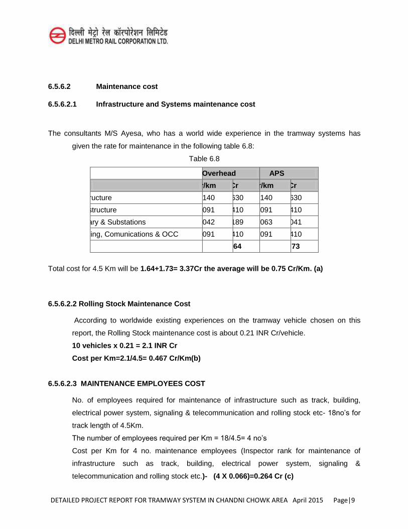
DETAILED PROJECT REPORT FOR TRAMWAY SYSTEM IN CHANDNI CHOWK AREA April 2015 Page|9
6.5.6.2 Maintenance cost
6.5.6.2.1 Infrastructure and Systems maintenance cost
The consultants M/S Ayesa, who has a world wide experience in the tramway systems has
given the rate for maintenance in the following table 6.8:
Table 6.8
Overhead APS
Item Cr/km Cr Cr/km Cr
Infrastructure 0.140 0.630 0.140 0.630
Superstructure 0.091 0.410 0.091 0.410
Catenary & Substations 0.042 0.189 0.063 0.041
Signalling, Comunications & OCC 0.091 0.410 0.091 0.410
1.64 1.73
Total cost for 4.5 Km will be 1.64+1.73= 3.37Cr the average will be 0.75 Cr/Km. (a)
6.5.6.2.2 Rolling Stock Maintenance Cost
According to worldwide existing experiences on the tramway vehicle chosen on this
report, the Rolling Stock maintenance cost is about 0.21 INR Cr/vehicle.
10 vehicles x 0.21 = 2.1 INR Cr
Cost per Km=2.1/4.5= 0.467 Cr/Km(b)
6.5.6.2.3 MAINTENANCE EMPLOYEES COST
No. of employees required for maintenance of infrastructure such as track, building,
electrical power system, signaling & telecommunication and rolling stock etc- 18no’s for
track length of 4.5Km.
The number of employees required per Km = 18/4.5= 4 no’s
Cost per Km for 4 no. maintenance employees (Inspector rank for maintenance of
infrastructure such as track, building, electrical power system, signaling &
telecommunication and rolling stock etc.)- (4 X 0.066)=0.264 Cr (c)
DETAILED PROJECT REPORT FOR TRAMWAY SYSTEM IN CHANDNI CHOWK AREA April 2015 Page|10
6.5.6.3 TOTAL OPERATION AND MAINTENANCE PER KM
Total maintenance cost per Km (a+b+c) can be taken as 0.75+0.467 + 0.264= 1.481 say
1.48 Cr/Km
The operational cost (from table 6.7)per Km will be 4.39/4.5 = 0.975 say 0.96 Cr.
Total of the operational + maintenance cost per Km = 1.48+0.96 = 2.44 Cr/Km
6.6 Depot operations The depot operations includes:
a. Cleaning of tramway cars b. Maintenance of tramway cars c. Workshop d. Stabling Yard e. Operation Control Centre
Depot operation will be covered in Operation Plan 6 months prior to the anticipated date of construction completion of project works.
6.7 Crew changeover arrangements
The crew changeover arrangement plan defines the working of crew operating the system. The Crew changeover plan should be easy and comfortable for the crew as well as the passenger to provide safe, secure, comfortable ride. The arrangement should be prepared considering the timetable so that the operation is not affected due to the changeover arrangement.
Crew Changeover Arrangement will be covered in Operation Plan 6 months prior to the anticipated date of construction completion of project works.
6.8 Incident management Incident management describes how the incident will be managed from occurrence to back-to-normal operation and provides information about the structure of the Incident Management Team, the criteria for invoking Business Continuity, the management of the incident, resource requirements, any necessary staff movements and critical processes.
6.8.1 Incident Response Plan
The Incident Response Plan is concerned with the immediate aftermath of an incident and is primarily concerned with keeping people safe. This plan should be prepared in consideration of Health and Safety and Security. The Incident Response Plan should provide details of:
The structure of the Incident Response Team
DETAILED PROJECT REPORT FOR TRAMWAY SYSTEM IN CHANDNI CHOWK AREA April 2015 Page|11
Members of the Emergency Response Team Roles and responsibilities of the Incident Response Team Muster Points Decision making process and escalation
In addition, the Incident Response Plan should detail procedures to:
Evacuate the building or shelter in site (“invacuate”) Move evacuated staff to a safe site Liaise with the emergency services Stabilise the situation immediately following an incident Communicate with people affected by the incident or impending incident – this
may include the public and neighbours Mobilisation of first aid, safety and evacuation assistance teams Account for those who were on site or in the immediate vicinity Locate safe site including details for accessing it Incident Room location and details for accessing it Interact with external agencies and regulatory authorities Ensure security or personnel, information and physical premises Assess the situation
6.8.2 Incident Management Plan The incident management plan should cover the following:
Scope and purpose of plan Relationship with other plans Definition of the Incident Response structure Handover from the Emergency Response Team Procedure for assessing the situation Roles and responsibilities of the Incident Management Team. Incident Room location and details for accessing it Location of an alternate Incident Room Invocation criteria Invocation procedure including rendezvous points and responsible persons Procedure for setting up and managing the Incident Room (this should include a
list of the required equipment, procedures and responsibilities for setting up PCs, telephones, teleconferencing or video-conferencing facilities, the layout of the room, location of a quiet room, details about catering arrangements, shift lengths, telephone numbers and so on.) If the room is a meeting room, it is beneficial to prepare a notice for the door, stating that in case of an incident the room must be vacated immediately
DETAILED PROJECT REPORT FOR TRAMWAY SYSTEM IN CHANDNI CHOWK AREA April 2015 Page|12
Action plans for implementing the Business Continuity response – it is helpful if these are included as a checklist giving an option to tick for every completed action. Sometimes it is useful to writethe action checklists separately for each member of the team as they can be printed and handed individually.
Recovery Profiles – these detail the critical activities to be recovered, the number of staff involved and their alternate location. The critical resource requirements for each critical activity will also be detailed and the timescale in which they are required
Resumption Process – this details how the organisation can resume normal operations following recovery of the critical processes. This may be a separate document or the organisation can decide how to manage this once the critical processes are operational and the organisation has stabilised
Details of equipment storage Maps and directions to all locations mentioned in the Plan Site access plans Claims management procedure Charts, plans (e.g. floor plans), photographs and other information which might
be useful Contact information:
o Senior Management Team o Incident Management Team o Team Leaders (all departments within the organisation) o External suppliers o Internal contacts o Regulatory bodies o Useful local information (e.g. hospital, doctors, plumbers, electrician, local
council) o Neighbours o Stakeholders
Communications Matrix Incident Log Incident Management stand-down procedures
o Decision to stand down o Who to communicate with o Filing of paperwork o Post incident report
6.8.3 Business Recovery Plan
Business Recovery Plans are to be prepared by the operational teams following an incident which affects their ability to operate normally. They provide information for teams to recover their processes for the Service Continuity Plan to be put into action. If
DETAILED PROJECT REPORT FOR TRAMWAY SYSTEM IN CHANDNI CHOWK AREA April 2015 Page|13
necessary the critical business units affected by the incident and the ones suffering a loss of critical technology or information will also activate their Business Recovery Plans.
The Business Recovery Plans should include:
Scope and purpose of plan Relationship to other plans Definition of the Business Unit Team Roles and responsibilities of the Business Unit Team. Procedure for assessing the situation Incident Room contact information Invocation criteria Escalation criteria Invocation procedure including rendezvous points and responsible persons Action plans for implementing the Business Continuity response it is helpful if
these are included as a checklist giving an option to tick for every completed action. Sometimes it is useful to writethe action checklists separately for each member of the team as they can be printed and handed individually. These action lists should cover the loss of each critical resource i.e. equipment, materials, technology and information, staff and buildings.
Recovery Profiles – these detail the critical activities to be recovered, the number of staff involved and their alternate location. The critical resource requirements for each critical activity will also be detailed and the timescale in which they are required
Details of equipment storage Maps and directions to all locations mentioned in the Plan Incident Log Communications Matrix Contact information:
o Incident Management Team o Other Bronze Team Leaders o External suppliers o Internal contacts o Regulatory bodies o Useful local information (e.g. hospital, doctors, plumbers, electrician, local
council) Recovery stand down procedures
o Decision to stand down o Who to communicate with o Filing of paperwork o Post incident report
DETAILED PROJECT REPORT FOR TRAMWAY SYSTEM IN CHANDNI CHOWK AREA April 2015 Page|14
6.8.4 Recovery Support Plan
Recovery Support Plans are aimed at the teams, who have a supporting role into the organisation and who, during an incident, would have very specific roles to play. They include, but are not limited to:
Human Resources Facilities Health and Safety Security Legal Alternate Site Co-ordination Original Site Salvage Damage Assessment
Incident Management Team should be aware of these plans and enlist the help of these departments if required. Representatives can be co-opted to the Incident Management Team, but if the incident has a far-reaching effect, it is advisable to invoke the organization-wide Incident Management Team which automatically includes the managers from these teams.
6.8.5 Communication and Media Plan
Procedures should be developed to disseminate and respond to requests for pre-incident, incident and post-incident information, as well as to provide information to internal and external audiences including the media, and to respond to their enquiries.Organizations should also establish and maintain the capability to provide accurate and up to date information for the organization and the public which includes:
Central contact point for the media Systems for gathering, monitoring and disseminating emergency information Pre-scripted information bulletins for potential disruption scenarios Method to co-ordinate and clear information for release Identification of the audience for communications (e.g. stakeholders, key
customers, staff, emergency services, suppliers, families, regulators, government ministers etc.)
Policies for communicating with the audience Policies for communicating with special needs populations Ongoing employee/customer communications and safety briefings Protective action guidelines (e.g. shelter at site, evacuation, move to safe site) Advice to the public through appropriate agencies concerning threats to the
people, property and the environment Definition of the means and frequency with which information will be provided
DETAILED PROJECT REPORT FOR TRAMWAY SYSTEM IN CHANDNI CHOWK AREA April 2015 Page|15
It is also suggested that a suitable venue should be established to support liaison with the media and other stakeholder groups, and that appropriate numbers of trained, competent spokespeople should be nominated and authorized to release information to the media.
A communications (or audience) matrix should be made to summarize the key information about the audience including who should communicate with each group. The key points of the message could also be noted in this matrix. It is useful to include this tool in all plans, to avoid confusion over who communicates with whom.
6.8.6 Business Resumption Plan
This plan details as to how the business unit can resume normal operations following recovery of their critical processes. This may be a separate document or a business plan may decide as to how to manage this once the critical processes are operational and the organization has stabilized.
While Business Continuity may necessarily involve adopting temporary measures (such as office relocation, reduction of working hours, reduction of staffing levels and/or usage of backup IT systems), business resumption is concerned with restoring operations to as near normal levels as possible.
Resumption may be to the original site or to a new location (depending on the damage sustained) and will need to be treated as a work programme in its own right, utilizing the information from the resource matrixes to develop a programme plan for reinstating normal operations in order of priority. The plan details the sequence, parties involved and other considerations (security, various timings, intermediate measures, communication, etc.)
6.9 Coordination with utility providers
For a smooth operation of system it must be updated with the utility services. For this a coordination plan is required. As per current scenario many utilities are influenced by LRT Network.
Coordination with utility provider will be covered in Operation Plan, 6 months prior to the anticipated date of construction completion of project works.
DETAILED PROJECT REPORT FOR TRAMWAY SYSTEM IN CHANDNI CHOWK AREA April 2015 Page|16
6.10 Procedures for staff recruitment and training 6.10.1 Recruitment
To begin with, it is important to carry out a job analysis to identify the sorts of skills, knowledge and essential requirements necessary for someone to do the job. These details can be set out in a job specification, which is passed on to recruiters - it gives them a picture of the ideal candidate.
The job description can be sent out to potential candidates along with a person specification, which sets out the desirable and essential characteristics that someone will need to have to be appointed to the post.
A variety of media will be used to attract applications e.g. national newspapers for national jobs, and local papers and media for local posts.
Following information should be provided for a Job advertisement:
location of work salary closing date of application how to apply experience required qualifications expected duties and responsibilities
6.10.2 Selection
Selection simply involves choosing the right person for the job. Effective selection requires that the organisation makes the right prediction from data available about the various candidates for a post. Research indicates that the most valid form of selection method is the use of an assessment centre where candidates are subjected to a variety of test including interviews, group exercises, presentations, 'in-tray' exercises, and so on.Interviews will be most successful when they are strictly related to job analysis, job description and the person specification.
In-tray exercises can be used for candidates to respond to work-related and other problems, which are presented to them in an in-tray to be processed.
6.10.3 Training
Training for employment is very important. In a modern economy, the nature of work is constantly changing. New technologies constantly demand new work skills. To succeed in a business or a career, people will have to be flexible about their work location and
DETAILED PROJECT REPORT FOR TRAMWAY SYSTEM IN CHANDNI CHOWK AREA April 2015 Page|17
style of work. They also need the desire to keep themselves updated and willing to change the range of skills they use at work.
There are mainly two types of training:
i. On the Job Training ii. Off the job Training
However, the Procedure plan for recruitment and training will be covered in Operation Plan 6 months prior to the anticipated date of construction completion of project works.
6.10.4 Management of reporting systems
The Management of Reporting System will be included in Operation Plan
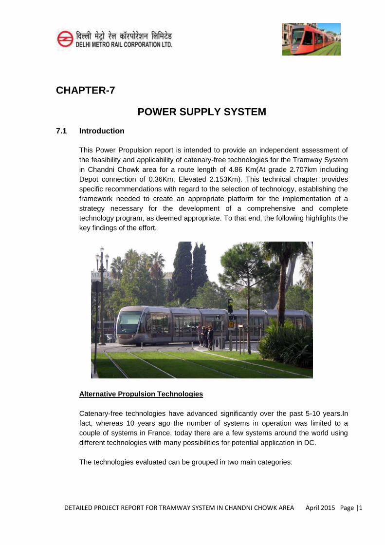
DETAILED PROJECT REPORT FOR TRAMWAY SYSTEM IN CHANDNI CHOWK AREA April 2015 Page |1
CHAPTER-7
POWER SUPPLY SYSTEM
7.1 Introduction
This Power Propulsion report is intended to provide an independent assessment of the feasibility and applicability of catenary-free technologies for the Tramway System in Chandni Chowk area for a route length of 4.86 Km(At grade 2.707km including Depot connection of 0.36Km, Elevated 2.153Km). This technical chapter provides specific recommendations with regard to the selection of technology, establishing the framework needed to create an appropriate platform for the implementation of a strategy necessary for the development of a comprehensive and complete technology program, as deemed appropriate. To that end, the following highlights the key findings of the effort.
Alternative Propulsion Technologies
Catenary-free technologies have advanced significantly over the past 5-10 years.In fact, whereas 10 years ago the number of systems in operation was limited to a couple of systems in France, today there are a few systems around the world using different technologies with many possibilities for potential application in DC.
The technologies evaluated can be grouped in two main categories:
DETAILED PROJECT REPORT FOR TRAMWAY SYSTEM IN CHANDNI CHOWK AREA April 2015 Page |2
1. Energy Storage Systems (ESS) – These technologies make use of power sources installed on the vehicle to allow for catenary-free operations. As such, these technologies may also be referred at times as On-Board/On- Tram technologies. Vehicles using this technology are powered by batteries, super capacitors, flywheels, fuel cells, diesel and/or alternative fuel sources or a combination of these power devices.
2. Ground Level Continuous Power Supply Systems (GLCPSS) – these technologies use ground level power sources instead of Overhead Contact Systems (OCS) to allow for catenary-free operations. As such, these technologies may also be referred at times as Infrastructure/Wayside and/or Off-Tram technologies.
These systems distribute power to the vehicle via induction, as it is the case with Bombardier’s PRIMOVE and Ansaldo’sTramWave technologies, or direct contact
with a power-rail installed between the running rails, in the case of ALSTOM’s APS
technology.
Some of the key advantages and disadvantages of each technology, for each of the categories noted above are included in this report. Before it can be determined that the introduction of catenary-free operations for the DC Tramway is feasible, the ultimate implementation strategy has to be developed for the deployment and implementation of such technology that takes into account the key elements that in the end will drive the application of any alternative propulsion technology, including the following:
Implication of proprietary systems and subsystems, this is particularly important when considering warranty, operations and maintenance of the new system and vehicles. Ground Level Continuous Power Supply Systems are usually proprietary systems and could result in significantly higher costs over the life of the asset.
Technical Specifications and Procurement, the level of detail required to appropriately procure the right technology for the implementation of catenary-free operations needs to be such that appropriate performance criteria are clearly defined while allowing some room for flexibility and innovation, required to trigger a competitive bid setting without compromising the long-term benefits of the investment.
Utility Relocations, catenary-free technologies may significantly reduce the need for utility prone to corrosion for relocation as the potential for stray-current leakage is minimal. This benefit would translate into significant infrastructure cost savings.
Wayside Infrastructure Requirements, irrespective of the technology, traction power substations would be required for any system. The location, power and
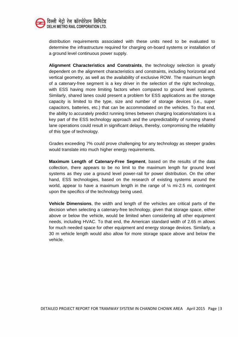
DETAILED PROJECT REPORT FOR TRAMWAY SYSTEM IN CHANDNI CHOWK AREA April 2015 Page |3
distribution requirements associated with these units need to be evaluated to determine the infrastructure required for charging on-board systems or installation of a ground level continuous power supply.
Alignment Characteristics and Constraints, the technology selection is greatly dependent on the alignment characteristics and constraints, including horizontal and vertical geometry, as well as the availability of exclusive ROW. The maximum length of a catenary-free segment is a key driver in the selection of the right technology, with ESS having more limiting factors when compared to ground level systems. Similarly, shared lanes could present a problem for ESS applications as the storage capacity is limited to the type, size and number of storage devices (i.e., super capacitors, batteries, etc.) that can be accommodated on the vehicles. To that end, the ability to accurately predict running times between charging locations/stations is a key part of the ESS technology approach and the unpredictability of running shared lane operations could result in significant delays, thereby, compromising the reliability of this type of technology.
Grades exceeding 7% could prove challenging for any technology as steeper grades would translate into much higher energy requirements.
Maximum Length of Catenary-Free Segment, based on the results of the data collection, there appears to be no limit to the maximum length for ground level systems as they use a ground level power-rail for power distribution. On the other hand, ESS technologies, based on the research of existing systems around the world, appear to have a maximum length in the range of ¼ mi-2.5 mi, contingent upon the specifics of the technology being used.
Vehicle Dimensions, the width and length of the vehicles are critical parts of the decision when selecting a catenary-free technology, given that storage space, either above or below the vehicle, would be limited when considering all other equipment needs, including HVAC. To that end, the American standard width of 2.65 m allows for much needed space for other equipment and energy storage devices. Similarly, a 30 m vehicle length would also allow for more storage space above and below the vehicle.
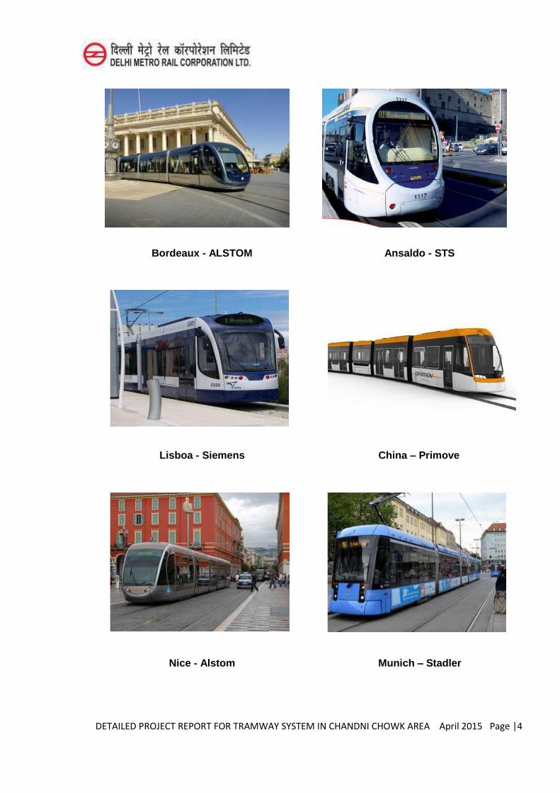
DETAILED PROJECT REPORT FOR TRAMWAY SYSTEM IN CHANDNI CHOWK AREA April 2015 Page |4
Bordeaux - ALSTOM Ansaldo - STS
Lisboa - Siemens China – Primove
Nice - Alstom Munich – Stadler
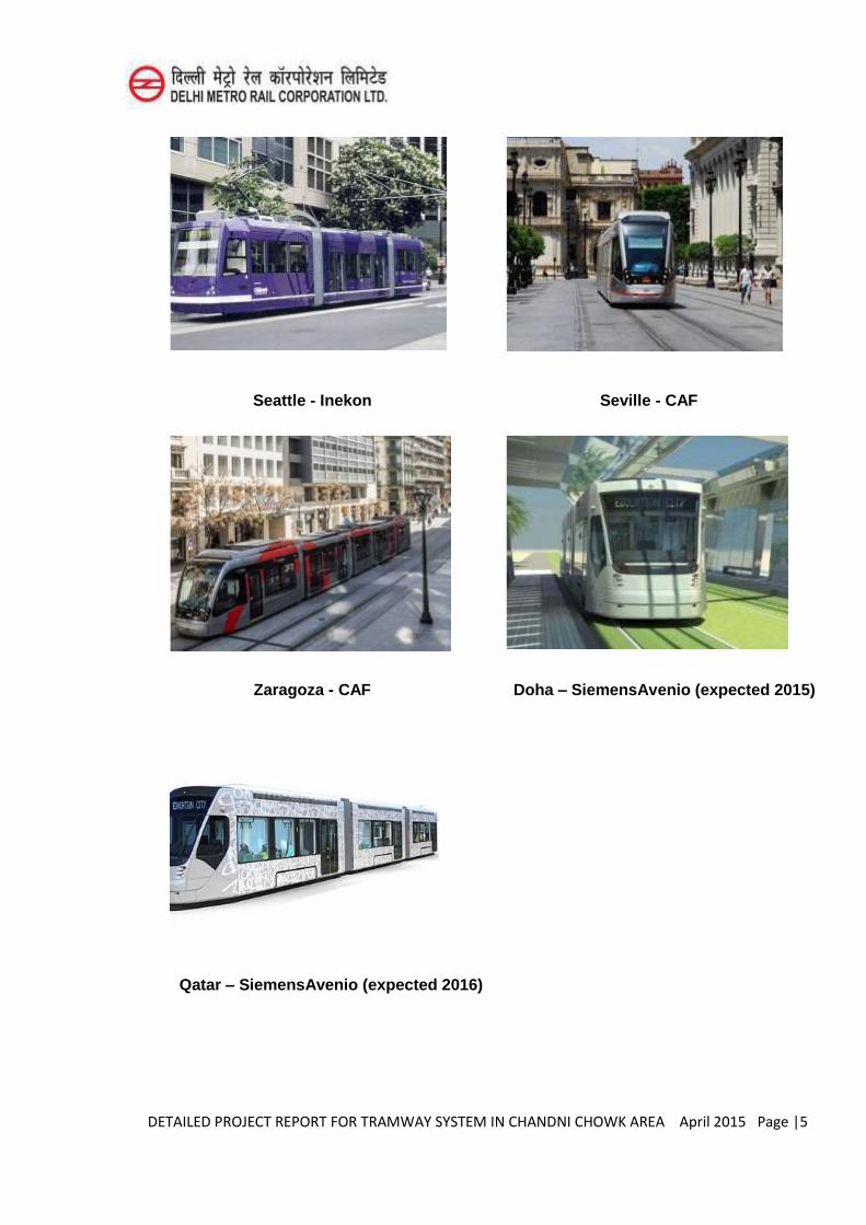
DETAILED PROJECT REPORT FOR TRAMWAY SYSTEM IN CHANDNI CHOWK AREA April 2015 Page |5
Seattle - Inekon Seville - CAF
Zaragoza - CAF Doha – SiemensAvenio (expected 2015)
Qatar – SiemensAvenio (expected 2016)
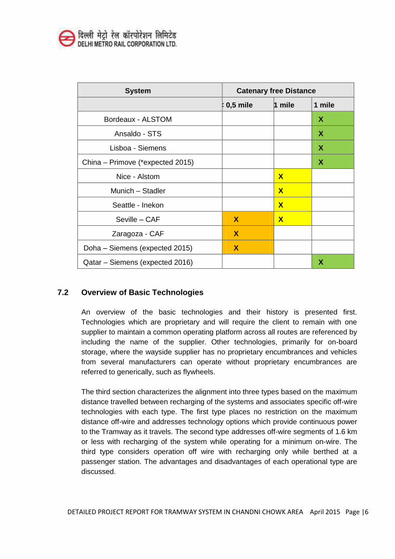
DETAILED PROJECT REPORT FOR TRAMWAY SYSTEM IN CHANDNI CHOWK AREA April 2015 Page |6
System Catenary free Distance
< 0,5 mile < 1 mile > 1 mile
Bordeaux - ALSTOM X
Ansaldo - STS X
Lisboa - Siemens X
China – Primove (*expected 2015) X
Nice - Alstom X
Munich – Stadler X
Seattle - Inekon X
Seville – CAF X X
Zaragoza - CAF X
Doha – Siemens (expected 2015) X
Qatar – Siemens (expected 2016) X
7.2 Overview of Basic Technologies
An overview of the basic technologies and their history is presented first. Technologies which are proprietary and will require the client to remain with one supplier to maintain a common operating platform across all routes are referenced by including the name of the supplier. Other technologies, primarily for on-board storage, where the wayside supplier has no proprietary encumbrances and vehicles from several manufacturers can operate without proprietary encumbrances are referred to generically, such as flywheels.
The third section characterizes the alignment into three types based on the maximum distance travelled between recharging of the systems and associates specific off-wire technologies with each type. The first type places no restriction on the maximum distance off-wire and addresses technology options which provide continuous power to the Tramway as it travels. The second type addresses off-wire segments of 1.6 km or less with recharging of the system while operating for a minimum on-wire. The third type considers operation off wire with recharging only while berthed at a passenger station. The advantages and disadvantages of each operational type are discussed.
DETAILED PROJECT REPORT FOR TRAMWAY SYSTEM IN CHANDNI CHOWK AREA April 2015 Page |7
Furthermore, comparison tables including some of the key advantages and disadvantages of each technology are also provided in this section along with a comprehensive discussion on the Operations and Maintenance implications, including a maintenance facility.
The fourth section briefly touches on Buy America compliance and the fifth section highlights a couple of issues related to the existing Tramway Design Criteria for further consideration, including recommended changes to maximize the number of potential suppliers with existing vehicle designs qualified to bid on a future procurement. This section includes a discussion of the possibility of retrofitting the District’s current Tramways and those on order with the selected technology to
enable off-wire operation.
The report concludes with findings and conclusions, including some of the key advantages and disadvantages of each technology evaluated as a part of this effort.
No part of this report is intended to provide endorsement of any manufacturer or vendor.
7.3 Propulsion Technologies
In the last decade new technologies have been developed by several Tramway manufacturers to satisfy the desire to eliminate overhead wiring in visually and historically sensitive areas and increase sustainability through maximizing the recovery of braking energy. A wide variety of technologies are being developed with some readily available for revenue service and others falling by the wayside. The review of these technologies, including alternative propulsion options and readiness for deployment, is critical for the Tramway System in ChandniChowk area, Delhi.
This said and acknowledging the rapid changes occurring in this technology arena, this study provides a snapshot of the state of these technologies at this period in time rather than a definitive assessment of the best technology available for application in DC.
The importance of selecting the appropriate technology for the alignment cannot be overstressed. National and international standards for the application, fabrication, certification, and operation of these vehicles are virtually non-existent and the characteristics of each alignment are used to develop a semi-custom solution based on the best available technology. When developing a complete system it is valuable to consider not only the current alignment, but also try to envisage the worst case future alignment on the projected complete system.
DETAILED PROJECT REPORT FOR TRAMWAY SYSTEM IN CHANDNI CHOWK AREA April 2015 Page |8
Most of the technologies reviewed are not applicable only to rail transit but also are being developed for buses and automobiles. Pertinent information from these two modes has been included where applicable.
7.3.1 Ground Level Power Supply
Currently two systems are being marketed that are able to provide continuous power to the vehicle at ground level while in motion without the use of an overhead line and pantograph. The two systems were developed by ALSTOM (APS) and Ansaldo STS (TramWave). One supplier, Bombardier, has demonstrated the ability of their system to provide power while in motion, but is currently deploying the system to provide in-ground recharging capability only at stops and short sections when the vehicle is accelerating from a stop. Additional systems are in varying stages of development by suppliers with and without transit experience.
Continuous power systems offer the advantage of full vehicle performance under all normal operating conditions, including full acceleration and braking, as well as the ability to climb hills or bridge approaches and maintain high capacity passenger area cooling. The systems are immune to the possibility of being stranded without power during long delays due to traffic conditions or other events in the off-wire portion.
In systems where power is supplied to the vehicles continuously, traction power substation locations and sizes will remain the same as for a traditional Tramway system. The cost of the ground level distribution system can be up to six times the cost of an equivalent overhead contact wire due to factors such as the use of independently switched sections which must be of a shorter length than the vehicle to avoid exposing the public to high voltages in the street.
ALSTOM APS
The ALSTOM APS (variously Alimentation par Sol or Aesthetic Power Supply) is the most widely deployed ground level power supply. The system is currently operating in revenue service in Bordeaux (2003), Angers (2011), Reims (2011) and Orleans (2012). It is also under construction in Tours (opening Sept. 2013) and Dubai (opening Nov. 2014). Problems with the start-up of the first installation in Bordeaux have been resolved and the City has extended the original wire-free segment of the line from 3 km in 1999 to 28 km today.
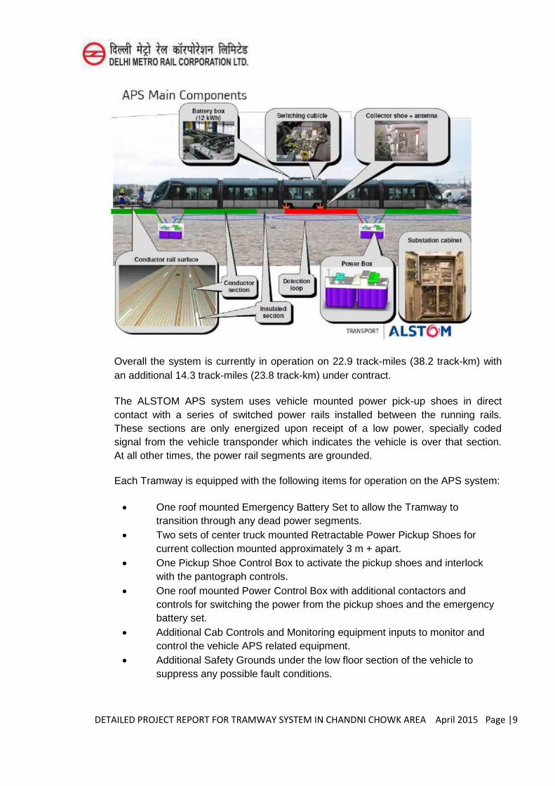
DETAILED PROJECT REPORT FOR TRAMWAY SYSTEM IN CHANDNI CHOWK AREA April 2015 Page |9
Overall the system is currently in operation on 22.9 track-miles (38.2 track-km) with an additional 14.3 track-miles (23.8 track-km) under contract.
The ALSTOM APS system uses vehicle mounted power pick-up shoes in direct contact with a series of switched power rails installed between the running rails. These sections are only energized upon receipt of a low power, specially coded signal from the vehicle transponder which indicates the vehicle is over that section. At all other times, the power rail segments are grounded.
Each Tramway is equipped with the following items for operation on the APS system:
One roof mounted Emergency Battery Set to allow the Tramway to transition through any dead power segments.
Two sets of center truck mounted Retractable Power Pickup Shoes for current collection mounted approximately 3 m + apart.
One Pickup Shoe Control Box to activate the pickup shoes and interlock with the pantograph controls.
One roof mounted Power Control Box with additional contactors and controls for switching the power from the pickup shoes and the emergency battery set.
Additional Cab Controls and Monitoring equipment inputs to monitor and control the vehicle APS related equipment.
Additional Safety Grounds under the low floor section of the vehicle to suppress any possible fault conditions.
DETAILED PROJECT REPORT FOR TRAMWAY SYSTEM IN CHANDNI CHOWK AREA April 2015 Page |10
The wayside installation of the APS system is made up of the following elements:
Low profile, sectional Power Rails – 11m long sections fitted with 8 m of conductor rail and 3 m of insulating rail with integral duct bank and vehicle detection loop.
Modular, quick replacement Power Rail Control Contactors – one is located every 22 m, controlling two segments of power rail.
Insulating Joint Boxes - one is located every 22 m and joinsthe ends of power rails not joined at the contactor boxes.
Substation Grounding Contactor and System Monitoring Cabinet –one is added to each substation.
In the APS system the lengths of the conductor/insulator rail segments are matched to the length of the Tramway. The lengths are set such that two adjacent active segments, followed by an inactive section at each end, are always covered by the Tramway. For a 30 m CITADIS Tramway or longer the lengths of the individual segments and shoe spacing on the vehicle correspond to the values provided above. The current APS design will not accommodate shorter Tramways, such as the CITADIS Compact, and would require redesign to shorten the segments. Shorter segments would increase the number of segments, power rail control contactor boxes and insulating joint boxes.
A variety of safeguards are designed into the system to prevent any single point failure from causing a hazardous condition. Key among these is acondition monitoring system in each substation that detects faults in any power rail segment within 200 milliseconds, disconnects and grounds the main feeder, automatically isolates the faulty segment and restores the system power to the remainder of the system in less than 2 seconds.
Electrically dead zones caused by an occasional faulty power rail segment contactor are traversed using vehicle on-board emergency battery sets with automatic transition to battery power when needed.
The proprietary APS system could in principle be retrofitted to many existing Tramways, but ALSTOM to date has not offered this system independent from procuring their matching CITADIS Tramways, hence little information on the system is available directly from ALSTOM sources.
Future orders of non-ALSTOM vehicles may be capable of being fitted with transponders, controls and pick-up shoe gear similar to that used on the CITADIS vehicles to allow operation on an APS equipped system, but such a supplier would be at a competitive disadvantage due to the up-front engineering cost required to design and integrate the additional equipment.
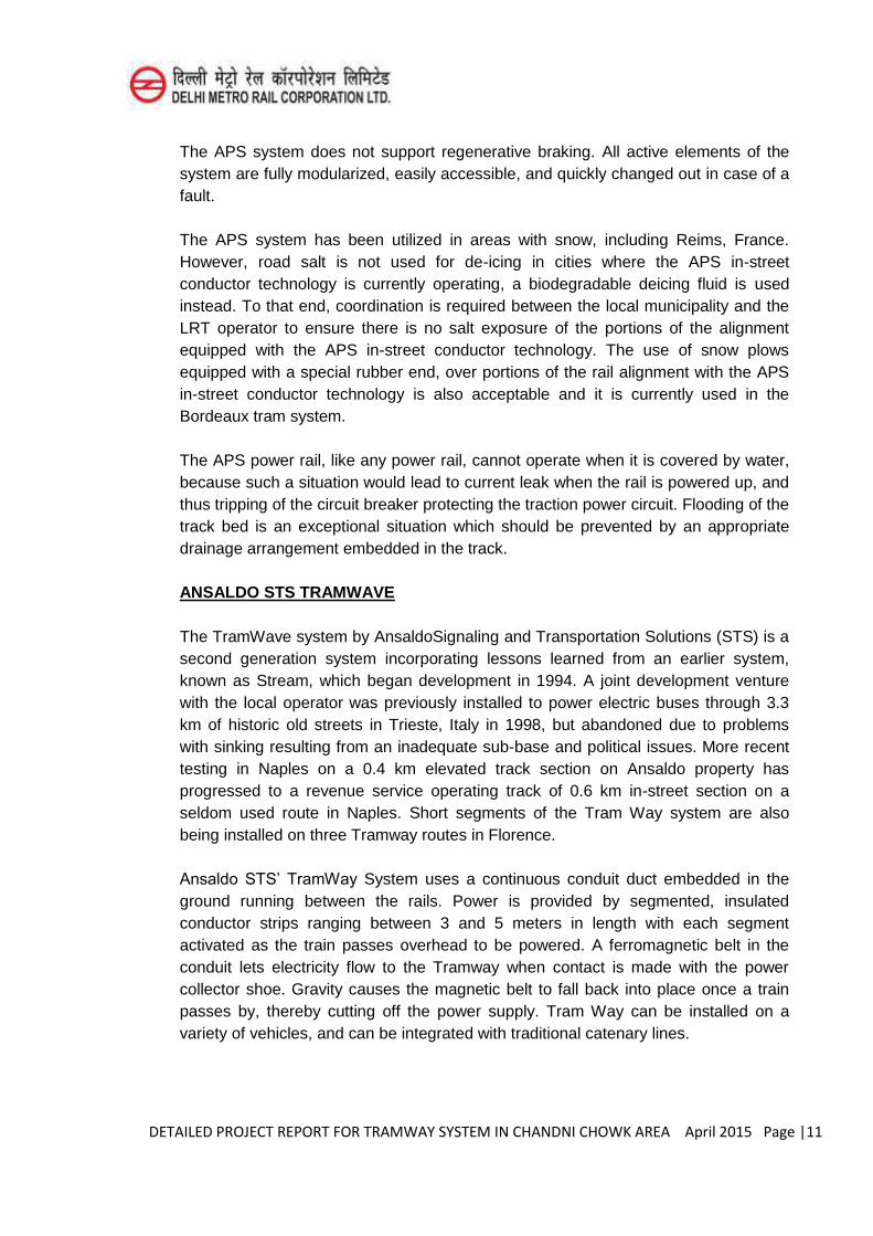
DETAILED PROJECT REPORT FOR TRAMWAY SYSTEM IN CHANDNI CHOWK AREA April 2015 Page |11
The APS system does not support regenerative braking. All active elements of the system are fully modularized, easily accessible, and quickly changed out in case of a fault.
The APS system has been utilized in areas with snow, including Reims, France. However, road salt is not used for de-icing in cities where the APS in-street conductor technology is currently operating, a biodegradable deicing fluid is used instead. To that end, coordination is required between the local municipality and the LRT operator to ensure there is no salt exposure of the portions of the alignment equipped with the APS in-street conductor technology. The use of snow plows equipped with a special rubber end, over portions of the rail alignment with the APS in-street conductor technology is also acceptable and it is currently used in the Bordeaux tram system.
The APS power rail, like any power rail, cannot operate when it is covered by water, because such a situation would lead to current leak when the rail is powered up, and thus tripping of the circuit breaker protecting the traction power circuit. Flooding of the track bed is an exceptional situation which should be prevented by an appropriate drainage arrangement embedded in the track.
ANSALDO STS TRAMWAVE
The TramWave system by AnsaldoSignaling and Transportation Solutions (STS) is a second generation system incorporating lessons learned from an earlier system, known as Stream, which began development in 1994. A joint development venture with the local operator was previously installed to power electric buses through 3.3 km of historic old streets in Trieste, Italy in 1998, but abandoned due to problems with sinking resulting from an inadequate sub-base and political issues. More recent testing in Naples on a 0.4 km elevated track section on Ansaldo property has progressed to a revenue service operating track of 0.6 km in-street section on a seldom used route in Naples. Short segments of the Tram Way system are also being installed on three Tramway routes in Florence.
Ansaldo STS’ TramWay System uses a continuous conduit duct embedded in the ground running between the rails. Power is provided by segmented, insulated conductor strips ranging between 3 and 5 meters in length with each segment activated as the train passes overhead to be powered. A ferromagnetic belt in the conduit lets electricity flow to the Tramway when contact is made with the power collector shoe. Gravity causes the magnetic belt to fall back into place once a train passes by, thereby cutting off the power supply. Tram Way can be installed on a variety of vehicles, and can be integrated with traditional catenary lines.
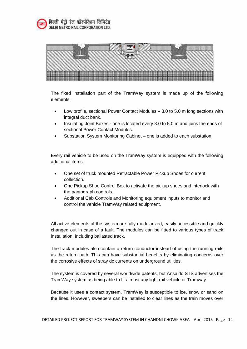
DETAILED PROJECT REPORT FOR TRAMWAY SYSTEM IN CHANDNI CHOWK AREA April 2015 Page |12
The fixed installation part of the TramWay system is made up of the following elements:
Low profile, sectional Power Contact Modules – 3.0 to 5.0 m long sections with integral duct bank.
Insulating Joint Boxes - one is located every 3.0 to 5.0 m and joins the ends of sectional Power Contact Modules.
Substation System Monitoring Cabinet – one is added to each substation.
Every rail vehicle to be used on the TramWay system is equipped with the following additional items:
One set of truck mounted Retractable Power Pickup Shoes for current collection.
One Pickup Shoe Control Box to activate the pickup shoes and interlock with the pantograph controls.
Additional Cab Controls and Monitoring equipment inputs to monitor and control the vehicle TramWay related equipment.
All active elements of the system are fully modularized, easily accessible and quickly changed out in case of a fault. The modules can be fitted to various types of track installation, including ballasted track.
The track modules also contain a return conductor instead of using the running rails as the return path. This can have substantial benefits by eliminating concerns over the corrosive effects of stray dc currents on underground utilities.
The system is covered by several worldwide patents, but Ansaldo STS advertises the TramWay system as being able to fit almost any light rail vehicle or Tramway.
Because it uses a contact system, TramWay is susceptible to ice, snow or sand on the lines. However, sweepers can be installed to clear lines as the train moves over
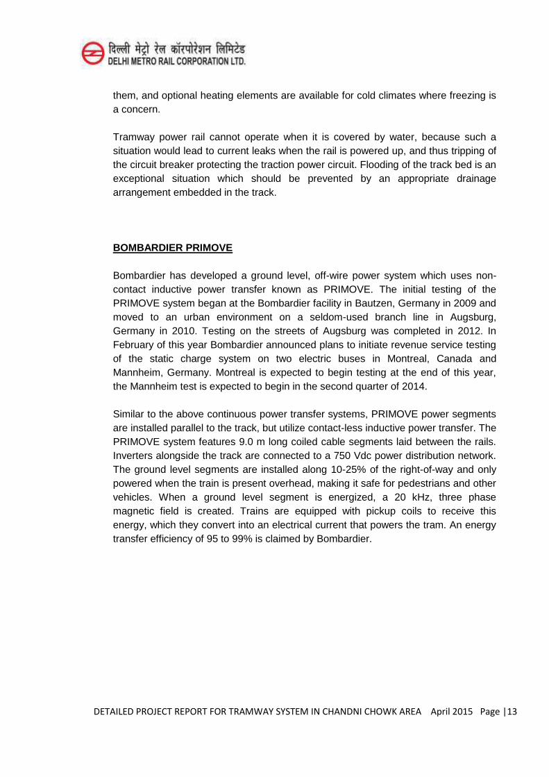
DETAILED PROJECT REPORT FOR TRAMWAY SYSTEM IN CHANDNI CHOWK AREA April 2015 Page |13
them, and optional heating elements are available for cold climates where freezing is a concern.
Tramway power rail cannot operate when it is covered by water, because such a situation would lead to current leaks when the rail is powered up, and thus tripping of the circuit breaker protecting the traction power circuit. Flooding of the track bed is an exceptional situation which should be prevented by an appropriate drainage arrangement embedded in the track.
BOMBARDIER PRIMOVE
Bombardier has developed a ground level, off-wire power system which uses non-contact inductive power transfer known as PRIMOVE. The initial testing of the PRIMOVE system began at the Bombardier facility in Bautzen, Germany in 2009 and moved to an urban environment on a seldom-used branch line in Augsburg, Germany in 2010. Testing on the streets of Augsburg was completed in 2012. In February of this year Bombardier announced plans to initiate revenue service testing of the static charge system on two electric buses in Montreal, Canada and Mannheim, Germany. Montreal is expected to begin testing at the end of this year, the Mannheim test is expected to begin in the second quarter of 2014.
Similar to the above continuous power transfer systems, PRIMOVE power segments are installed parallel to the track, but utilize contact-less inductive power transfer. The PRIMOVE system features 9.0 m long coiled cable segments laid between the rails. Inverters alongside the track are connected to a 750 Vdc power distribution network. The ground level segments are installed along 10-25% of the right-of-way and only powered when the train is present overhead, making it safe for pedestrians and other vehicles. When a ground level segment is energized, a 20 kHz, three phase magnetic field is created. Trains are equipped with pickup coils to receive this energy, which they convert into an electrical current that powers the tram. An energy transfer efficiency of 95 to 99% is claimed by Bombardier.
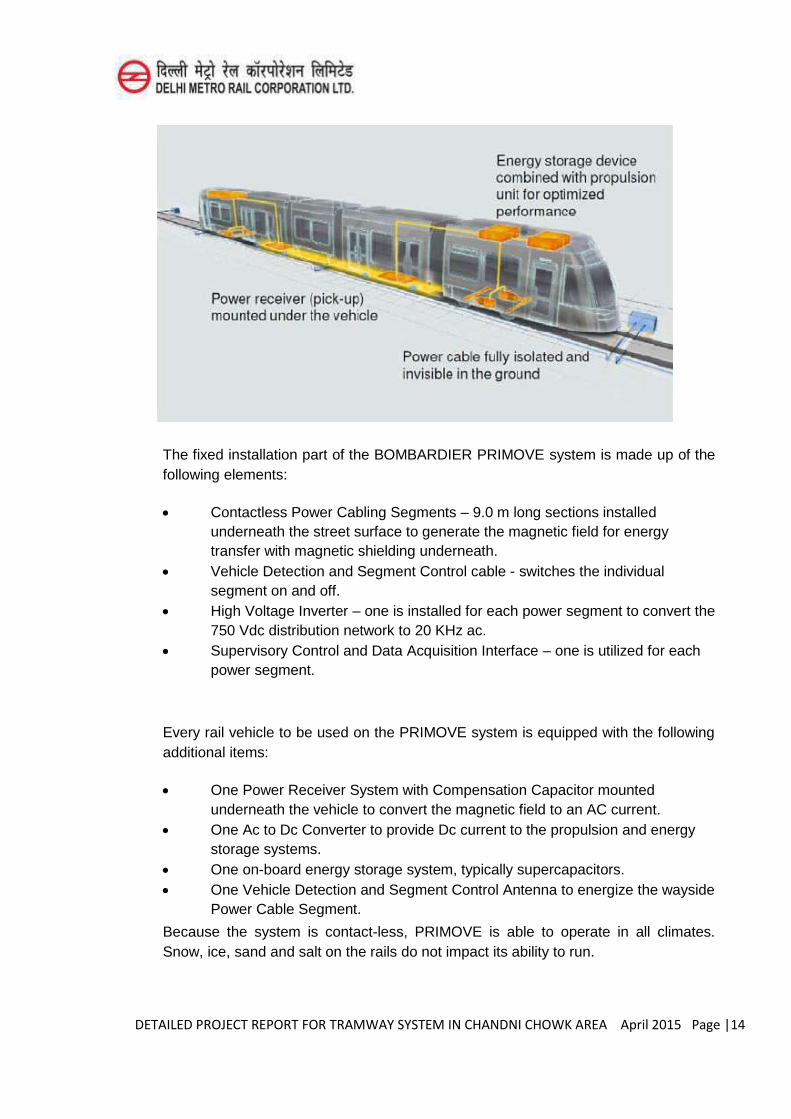
DETAILED PROJECT REPORT FOR TRAMWAY SYSTEM IN CHANDNI CHOWK AREA April 2015 Page |14
The fixed installation part of the BOMBARDIER PRIMOVE system is made up of the following elements:
Contactless Power Cabling Segments – 9.0 m long sections installed underneath the street surface to generate the magnetic field for energy transfer with magnetic shielding underneath.
Vehicle Detection and Segment Control cable - switches the individual segment on and off.
High Voltage Inverter – one is installed for each power segment to convert the 750 Vdc distribution network to 20 KHz ac.
Supervisory Control and Data Acquisition Interface – one is utilized for each power segment.
Every rail vehicle to be used on the PRIMOVE system is equipped with the following additional items:
One Power Receiver System with Compensation Capacitor mounted underneath the vehicle to convert the magnetic field to an AC current.
One Ac to Dc Converter to provide Dc current to the propulsion and energy storage systems.
One on-board energy storage system, typically supercapacitors. One Vehicle Detection and Segment Control Antenna to energize the wayside
Power Cable Segment.
Because the system is contact-less, PRIMOVE is able to operate in all climates. Snow, ice, sand and salt on the rails do not impact its ability to run.
DETAILED PROJECT REPORT FOR TRAMWAY SYSTEM IN CHANDNI CHOWK AREA April 2015 Page |15
However, this advantage causes a unique set of challenges. High power, high frequency EMC/EMI emissions can potentially cause safety problems with electronic devices, possibly including a passenger’s pacemaker, electrical cabling parallel to the
power transfer segment, and vehicle controls. Bombardier has carefully engineered the system to minimize this risk and meet all applicable EMC codes and standards.
The track modules also contain a return conductor instead of using the running rails as the return path. This can have substantial benefits by eliminating concerns over the corrosive effects of stray dc currents on underground utilities.
Other Inductive Charging Systems
Numerous other companies are developing inductive charging solutions for automobiles and transit vehicles. The list of companies includes industry mainstays such as the German firm Wampler, new start-ups such as HaloIPT of Great Britain, and university spin-offs such as WAVE in Utah. Many of these systems are showing promise for future applications.
The diversity of power transfer methods and lack of national and international standards defining the power transfer interface means each wayside system must be paired with an on-board vehicle system from the same manufacturer.
7.3.2 On Board Energy Supply On-board energy supply systems can store energy electrically, chemically, or
mechanically. The diversity of devices used includes supercapacitors, batteries, flywheels, fuel tanks, and fuel cells. All of these systems store energy on-board the vehicle and that energy must be periodically renewed from wayside facilities. There is a great variation in distance that can be travelled prior to renewal as well as the readiness of the different systems to be installed on an operating Tramway system.
The systems may offer either full or reduced performance depending on the maximum charge/discharge rates permitted. The number of recharge cycles in the useable lifetime of some of these devices is limited.
Additionally, since the amount of energy stored is finite, a vehicle may be left stranded without power if long delays are encountered due to traffic conditions or other events on the off-wire portion.
The vehicles may have no impact on a traditional traction power supply system, may alter the system substantially, or eliminate it completely with the new requirements for fuel storage and handling.
DETAILED PROJECT REPORT FOR TRAMWAY SYSTEM IN CHANDNI CHOWK AREA April 2015 Page |16
Supercapacitors
Supercapacitors (sometimes referred to as ultra-capacitors) have been installed on revenue service vehicles by almost all major international carbuilders. Their primary purpose has been to increase regeneration and lower energy consumption though they are also used for off-wireoperation. Vehicles with supercapacitors designed for off-wire operation are normally also provided with a small battery bank to extend the off-wiretime and/or provide for hotel loads such as HVAC.
Bombardier was the first to demonstrate supercapacitors in revenue service in Mannheim, Germany from 2003 to 2007. Mannheim followed in 2007 with the first supercapacitor equipped vehicle order for 19 additional cars and another 11 cars in 2011. ALSTOM has supplied a tram in 2009 to Paris which is equipped with supercapacitors that currently runs in revenue service off-wire on two sections of line T3: Georges Brassens to Brancion and Porte de Choisy to Porte d‘Italie. Ansaldo
STS has a supercapacitor equipped Sirio tram undergoing evaluation in Florence, Italy. The Spanish firm Construcciones y Auxiliar de Ferrocarriles SA (CAF) initially supplied vehicles with supercapacitors for off-wire operation to Seville in 2010 to accommodate a religious procession where overhead wires would have interfered. Subsequently CAF supplied off-wire vehicles to Zaragoza, Spain in 2011, and won additional orders for Granada, Spain in 2010 and Kaohsiung, Taiwan in 2012. SIEMENS offers supercapacitors as part of their standard Mobile Energy Storage (MES) designed to fit on the roof of any vehicle. Additionally VosslohKiepke is building Tramways equipped with supercapacitors for Leon, Spain and Rostock, Germany.
In the United States a demonstration project funded by a TIGER III grant is being conducted by Tri-Met in Portland, Oregon. Supercapacitor banks from American Maglev Technologies are being fitted to twenty SIEMENS LRVs which will operate in revenue service. The installation is intended primarily to increase efficiency and reduce substation demand during peak periods. Off-wire operation will also be tested at speeds up to 25 mph with distances of 762 m on level track being expected.
Supercapacitors, or double-layer capacitors, store their energy electrically in an electrostatic field. These units are basically very large versions of the well-known capacitors used in electronic circuits. Like normal capacitors, they basically consist of two metallic plates isolated from each other by a non-conducting dielectric material. The main difference is that these units are much larger in size and capacity, with unit ratings of up to 160 farads and 45 Kilojoules of energy storage capacity at 300 to 500 volts.
Supercapacitors have wide-ranging applications other than rail transit and available virtually off the shelf.
DETAILED PROJECT REPORT FOR TRAMWAY SYSTEM IN CHANDNI CHOWK AREA April 2015 Page |17
The supercapacitor system charging/discharging rate is very fast, measured in seconds, and they can withstand repeated charge/discharge cycling without significant degradation over time. Design life does vary somewhat depending on the degree of cycling but has been claimed to be on the order of 23 to 30 years.
Batteries
Batteries have been installed on revenue service vehicles since the beginning of horse-less operation in the mid 1800’s which predates the use of an overhead contact wire. Batteries are also the most diverse type of on-board energy storage and include the traditional lead-acid, widelyused nickel cadmium types, as well as the newer nickel-iron, nickel-metal hydride, nickel-zinc, sodium-sulfur, lithium-iron disulfide, lithium-ion, lithium-polymer, lithium-thionyl chloride, lithium-sulfur dioxide, lithiummanganese dioxide, zinc-air, zinc-dibromide and numerous other types.
Due to this wide variety, generalities concerning their performance characteristics, cost, weight, safety, maintenance and space requirements are difficult. Each battery type must be considered independently.
All types of batteries store energy chemically. The requirement of a chemical reaction results in a longer time to charge and discharge the battery with charging usually measured in hours, rather than seconds. The slow discharge rate usually results in a lower vehicle acceleration and overall performance. On the plus side, batteries can store more energy per unit weight than other on-board storage devices such as supercapacitors and flywheels. For long distances off-wire batteries are far superior to either supercapacitors or flywheels.
All batteries also show a reduction in life based on the number of charge/discharge cycles and the depth of the discharge. Battery capacity is often oversized to minimize the depth of discharge in normal service. Typical expected lifetimes will be in the 5 to 10 year range.
Improvements in battery performance are continuously emerging, driven mostly by developments for the automotive and cell phone industries.
Lead Acid Lead acid batteries have been used on rail vehicles since the 1800’s and are widely
distributed throughout the transportation industry, including almost all automobiles. However, they are very heavy compared to the energy they can store and rely on an environmental contaminant, lead.
These batteries, until recently, have been used by ALSTOM as a back-up to the APS system in cities such as Bordeaux.
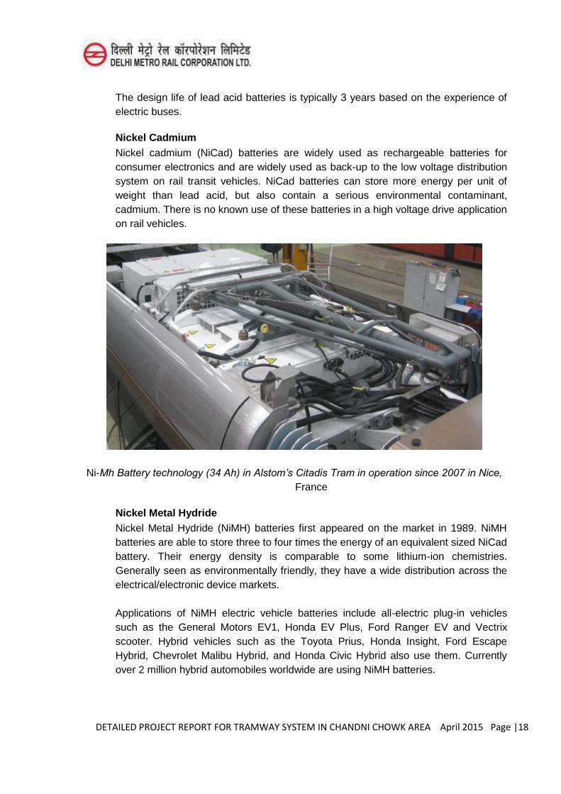
DETAILED PROJECT REPORT FOR TRAMWAY SYSTEM IN CHANDNI CHOWK AREA April 2015 Page |18
The design life of lead acid batteries is typically 3 years based on the experience of electric buses.
Nickel Cadmium Nickel cadmium (NiCad) batteries are widely used as rechargeable batteries for
consumer electronics and are widely used as back-up to the low voltage distribution system on rail transit vehicles. NiCad batteries can store more energy per unit of weight than lead acid, but also contain a serious environmental contaminant, cadmium. There is no known use of these batteries in a high voltage drive application on rail vehicles.
Ni-Mh Battery technology (34 Ah) in Alstom’s Citadis Tram in operation since 2007 in Nice,
France
Nickel Metal Hydride Nickel Metal Hydride (NiMH) batteries first appeared on the market in 1989. NiMH
batteries are able to store three to four times the energy of an equivalent sized NiCad battery. Their energy density is comparable to some lithium-ion chemistries. Generally seen as environmentally friendly, they have a wide distribution across the electrical/electronic device markets.
Applications of NiMH electric vehicle batteries include all-electric plug-in vehicles such as the General Motors EV1, Honda EV Plus, Ford Ranger EV and Vectrix scooter. Hybrid vehicles such as the Toyota Prius, Honda Insight, Ford Escape Hybrid, Chevrolet Malibu Hybrid, and Honda Civic Hybrid also use them. Currently over 2 million hybrid automobiles worldwide are using NiMH batteries.

DETAILED PROJECT REPORT FOR TRAMWAY SYSTEM IN CHANDNI CHOWK AREA April 2015 Page |19
The first modern battery-driven off-wire Tramway uses NiMH batteries. The ALSTOM CITADISTramway entered service in Nice, France in 2007. Since then these batteries have gained widespread acceptance from the larger Tramway manufacturers including ALSTOM, Ansaldo, Bombardier, CAF, Kawasaki, and SIEMENS.
NiMH batteries require both a battery management and a thermal management control system. Charging currents, particularly fast charging, need to be controlled to prevent over-charging and damage to the cell.
Damage and reduced life may also occur with “trickle charging” a fully charged
battery. The operational temperature range of a Tramway typically exceeds the operational temperature range of the battery requiring the use of both heating and cooling of the battery to achieve the performance and lifetime specified by the manufacturer. Overcharging or overheating of a NiMH battery may result in the release of hydrogen gas.
Lithium-ion Lithium-ion (Li-) batteries are very promising because they are lighter, more compact,
and can store more energy at sufficient power, but they are a diverse family of chemistries, each with their own strengths and weaknesses. The newer lithium-iron phosphate batteries have high storage capacity, but not as high as the more common lithium cobalt-oxide batteries. However, the latter tend to overheat and may catch fire or explode due to runway oxidation reactions of the graphite electrode. Nano lithium-titanate batteries store sufficient energy and power with greater chemical stability and improved thermal safety. Emerging lithium-polymer, lithium-sulfur, and lithium-air batteries are expected to bring noticeable improvements in energy storage/recharging capabilities which are double or quadruple today’s capabilities.
These future batteries are expected to be lower weight, smaller in size, with longer life and a higher temperature operating range. Each chemistry has specific application, handling, and storage requirements and the continued production and availability of a specific chemistry is not a certainty. Until a preferred chemistry is established by the automotive or transit industries, it is not possible to recommend one specific type.
Applications of Li-batteries in the automobile industry have been primarily limited to all electric and “plug-in” hybrids. All electric vehicles include the
Nissan Leaf and upstarts such as Fisker Automotive. The “plug-in” hybrids include
the General Motors Volt and the Toyota Prius. Detailed information on these batteries is difficult to obtain and often considered proprietary, however the general chemistry is known. Fisker Automotive is using lithium cobalt oxide which is the same chemistry used in the Boeing 787 batteries which have had fire/safety problems. The Nissan Leaf is using manganese dioxide technology but is expected to change to nickel

DETAILED PROJECT REPORT FOR TRAMWAY SYSTEM IN CHANDNI CHOWK AREA April 2015 Page |20
manganese cobalt in the near future. Nickel manganese cobalt is also used in the Prius plug-in. The GM Volt uses lithium manganese spinel.
Which, if any, of these chemistries will be used going forward is impossible to predict. However the limitation in life span can permit adoption of batteries with upgraded technology during replacement.
The use of Li-batteries in modern Tramways is a new development with the only examples in service being small trolleys used in shopping centers such as The Grove in California and custom built by Gomaco Trolley or TiG/m. Stadler Rail has demonstrated operation of a Li-battery equipped Tramway in Munich, Germany and the local transit authority has ordered four of the vehicles. In Kinki Sharyo has built a demonstrator prototype, the ameriTRAM, which has toured several cities though no orders are known to be forthcoming. Two car builders have orders to supply Tramways with off-wire running based on Li-batteries.
Li-batteries require rigorous care with both battery management for charge/discharge control and thermal management for both heating and cooling. The different chemistries impose different conditions for these systems on the vehicles. Two of the most stable chemistries, lithium titanate (proprietary to A123) and lithium iron phosphate (several suppliers) have widely different cell voltages with lithium titanate having a maximum cell voltage of 2.8 V and lithium iron phosphate having a maximum cell voltage of 3.65 V. The nickel manganese cobalt type currently being deployed on automobiles has a maximum cell voltage of4.2 V. Any change in battery type is likely to require replacement of the battery and thermal management systems also. This could be very problematic if the battery management systems are incorporated into the propulsion system controls.
Currently both the National Fire Protection Association (NFPA) and the National Highway Traffic Safety Administration (NHTSA) are developing standards for the use of high voltage battery sets in vehicles. In January of 2012 the NHSTA released a document titled “Interim Guidance for Electric and Hybrid-Electric Vehicles Equipped with High Voltage Batteries”. The document is in response to fires in the General
Motors Volt during crash testing. While re-affirming that Li- are not unsafe it does note that fires and release of toxic flammable gases after a crash are possible. Detailed requirements for the physical protection of Li-batteries may be forthcoming. In terms of applicability to Tramways, it is advisable for the owner to seriously review designs such as the Kinki Sharyo’s ameriTRAM where batteries are mounted on the
side of the vehicle and protrude into the passenger compartment. This location will be highly susceptible to impacts from traffic accidents. The proposed retrofits to the Boeing 787 airliner in response to fire in the Li- batteries include housing the batteries in an explosion-proof container and venting any gases to the outside of the airplane.
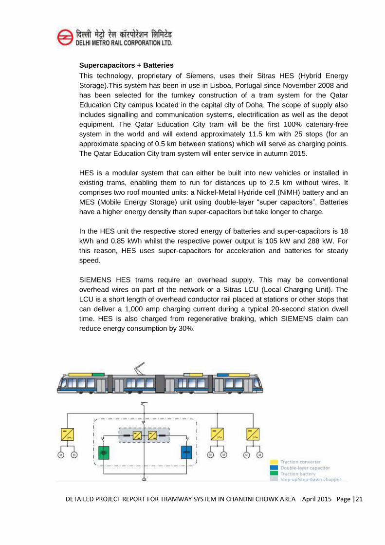
DETAILED PROJECT REPORT FOR TRAMWAY SYSTEM IN CHANDNI CHOWK AREA April 2015 Page |21
Supercapacitors + Batteries This technology, proprietary of Siemens, uses their Sitras HES (Hybrid Energy
Storage).This system has been in use in Lisboa, Portugal since November 2008 and has been selected for the turnkey construction of a tram system for the Qatar Education City campus located in the capital city of Doha. The scope of supply also includes signalling and communication systems, electrification as well as the depot equipment. The Qatar Education City tram will be the first 100% catenary-free system in the world and will extend approximately 11.5 km with 25 stops (for an approximate spacing of 0.5 km between stations) which will serve as charging points. The Qatar Education City tram system will enter service in autumn 2015.
HES is a modular system that can either be built into new vehicles or installed in existing trams, enabling them to run for distances up to 2.5 km without wires. It comprises two roof mounted units: a Nickel-Metal Hydride cell (NiMH) battery and an MES (Mobile Energy Storage) unit using double-layer “super capacitors”. Batteries
have a higher energy density than super-capacitors but take longer to charge.
In the HES unit the respective stored energy of batteries and super-capacitors is 18 kWh and 0.85 kWh whilst the respective power output is 105 kW and 288 kW. For this reason, HES uses super-capacitors for acceleration and batteries for steady speed.
SIEMENS HES trams require an overhead supply. This may be conventional overhead wires on part of the network or a Sitras LCU (Local Charging Unit). The LCU is a short length of overhead conductor rail placed at stations or other stops that can deliver a 1,000 amp charging current during a typical 20-second station dwell time. HES is also charged from regenerative braking, which SIEMENS claim can reduce energy consumption by 30%.
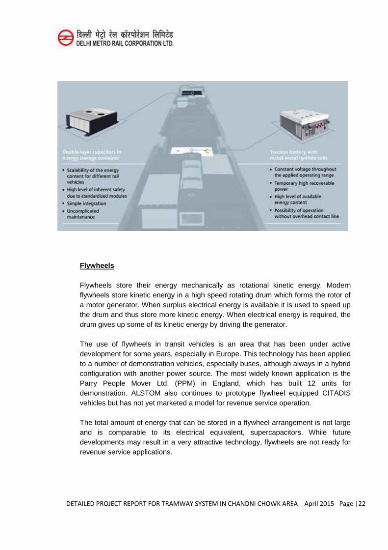
DETAILED PROJECT REPORT FOR TRAMWAY SYSTEM IN CHANDNI CHOWK AREA April 2015 Page |22
Flywheels
Flywheels store their energy mechanically as rotational kinetic energy. Modern flywheels store kinetic energy in a high speed rotating drum which forms the rotor of a motor generator. When surplus electrical energy is available it is used to speed up the drum and thus store more kinetic energy. When electrical energy is required, the drum gives up some of its kinetic energy by driving the generator.
The use of flywheels in transit vehicles is an area that has been under active development for some years, especially in Europe. This technology has been applied to a number of demonstration vehicles, especially buses, although always in a hybrid configuration with another power source. The most widely known application is the Parry People Mover Ltd. (PPM) in England, which has built 12 units for demonstration. ALSTOM also continues to prototype flywheel equipped CITADIS vehicles but has not yet marketed a model for revenue service operation.
The total amount of energy that can be stored in a flywheel arrangement is not large and is comparable to its electrical equivalent, supercapacitors. While future developments may result in a very attractive technology, flywheels are not ready for revenue service applications.
DETAILED PROJECT REPORT FOR TRAMWAY SYSTEM IN CHANDNI CHOWK AREA April 2015 Page |23
Fuel Tanks
Storing energy on board the vehicle as a combustible fuel used to power an engine or turbine is a technology more traditionally used for long distance interurban rail travel. The fuel is typically diesel or liquefied natural gas (LNG). Urban applications of this technology are well established in bus operations with fuelling facilities incorporated into the maintenance yards. Adapting this technology to modern low floor Tramways based on electric drive technology is difficult, and not cost effective considering the wide availability of buses.
The one known application of this technology was the adaptation of a SIEMENS CombinoTramway to run on diesel outside the urban core where an overhead electrical supply was not available. Three vehicles in Nordhausen, Germany were outfitted with a diesel engine and fuel tank inside the passenger compartment. They have been performing well with the exception of a fire in the passenger compartment caused by a leaky fuel line in 2010.
Compressed Natural Gas (CNG) is a mature technology for buses, but does not appear to have had much success in the Tramway world.
Fuel Cells
Fuel cells are a promising technology for direct conversion of a fuel to electrical power without the need for an engine or turbine. In 2012 there were 25 active bus demonstrations in eight locations. The two most common fuels have been hydrogen and methanol. Methanol was used in the local demonstration project at Georgetown University that ended in July 2011 due to a lack of funding. Almost all work on this technology has been performed on buses with no known applications to Tramways.
Car Builder’s Perspective As noted in the Executive Summary, the data collection effort conducted as a part of
this study included a series of interviews with a diverse group of car builders. To that end, the list of potential car builders with the ability and capacity to provide DC with catenary-free technologies is included below. Due to the limits of the scope of this effort, technical informative sessions were held with only six car builders, including SIEMENS, BOMBARDIER, KINKI SHARYO, CAF and ALSTOM. A robust and comprehensive industry forum and outreach program should be considered as the catenary-free technology program is further defined in the next stages of the project development process. The text below is intended to provide some insight into the state of catenary-free technologies from the car builder’s perspective.
DETAILED PROJECT REPORT FOR TRAMWAY SYSTEM IN CHANDNI CHOWK AREA April 2015 Page |24
SIEMENS
SIEMENS is a multinational engineering company based on Munich, Germany with services on rail-based mobility; from trams, light rail and metro services, to commuter rail lines up to regional services. They have been building trams since they provided the world with its first electric tram powered from overhead wires in Berlin in May 1881. SIEMENS currently offers catenary-free trams using their Sitras HES (Hybrid Energy Storage).
BOMBARDIER
Bombardier is multinational Aerospace and Transportation Company with headquarters in Montreal, Canada. Their PRIMOVE system provides a contactless power source solution for all types of electric transport, from light rail and bus networks to commercial vehicles and cars, by using the principles of inductive power transfer. This system has the advantage of being entirely hidden as the inductive loops between the tracks used to transmit power to trams are safely contained underground. These loops need to be covered by a 40mm layer of non-conductive material such as resin, asphalt base or non-reinforced concrete which may need to be carefully installed or it might be vulnerable to heavy traffic. Each looped cable segment is eight meters long and transmits 200kw. It is fed by an inverter which transforms 750 volt DC into 200 kHz AC. This system has transmission efficiencies of between 90% and 95%, which Bombardier advises is only 2% less than contact systems. PRIMOVE is only switched on when the tram is above it by a maintenance-free solid-state unit. Power transmission loops are generally located at stations and gradients as required by the tram network. The PRIMOVE system allows electric vehicles to be wirelessly recharged either in motion (dynamic charging) or at rest (static charging) without affecting journey times and it can be recharged completely in about 30 seconds. The loops fit above sleepers and so involve no additional civil engineering costs. This system does not continuously power the tram so energy storage is an essential aspect of the PRIMOVE system. Bombardier’s MITRAC
Energy Saver uses supercapacitors and was originally designed to store energy from regenerative braking. Trials have shown savings of up to 30% of traction energy.
The PRIMOVE concept has been successfully demonstrated in Augsburg, Germany where Bombardier low-floor trams have been tested on an 800 m spur line to the city’s exhibition center for operation in sand, snow, and salty slush conditions.
Further testing has been done at Bombardier’s hub in Mannheim which opened in September 2011 and which has also tested PRIMOVE buses, minivans, and cars.
Bombardier Transportation has successfully completed the testing of its PRIMOVE catenary-free power system on a branch of the Augsburg tram network as mentioned above. Nonetheless, Augsburg transport operator AVG, does not plan to deploy
DETAILED PROJECT REPORT FOR TRAMWAY SYSTEM IN CHANDNI CHOWK AREA April 2015 Page |25
PRIMOVE trams, but the federal government has awarded funding for Bombardier and Braunschweig transport operator BSVAG to undertake in-service trials with two electric buses which will run on a 12 km route.
7.4 Application and Selection
7.4.1 Selection of Alternate Propulsion System Designing a system for off-wire operation using periodic power transmission/energy
storage devices is a complex task which must dynamically balance the energy stored on the vehicle against the energy requirements of the areas to be operated without an overhead distribution system. In order to optimize the type and size of the vehicle on-board energy storage devices to be used, a rigorous set of engineering calculations must be performed.
The first step in this process is to accurately define the route and fully identify the areas where wireless operations are required and/or desired.
This information is used to perform standard propulsion system simulations that calculate energy consumption of both the propulsion performance and auxiliary power loads such as HVAC. Such simulations typically include:
Speed limits and maximum operating speed Acceleration and braking performance Stationdwell times Number and location of station stops Number and location of traffic lights Vertical grade details Any other alignment details and/or characteristics which may affect vehicle
operations
For the Alternatives Analysis several assumptions have been made to assess the potential application of catenary-free operations currently in revenue operations in other cities. To that end, we’ve classified existing systems in revenue operations into
three categories, based on the maximum distance traveled off wire. The three categories are:
Distances greater than one mile (1.6 km) Distances greater than one half mile (0.8 km) Distances shorter than one half mile (0.8 km)
DETAILED PROJECT REPORT FOR TRAMWAY SYSTEM IN CHANDNI CHOWK AREA April 2015 Page |26
The classifications are intended to be very conservative and actual distances may be greater after an engineering analysis is performed.Reserve capacity of the storage system will also need to be established during preliminary engineering for the line. The reserved capacity is needed for:
Limiting the “depth-of-discharge” for the storage devices to achieve maximum
lifespan (the deeper the discharge, the shorter the life); Allow for delays due to traffic without stranding a vehicle without power; and Allow for system faults which may reduce the available power.
The table below summarizes some relevant technology applications around the world that could be used for comparisons for potential applications in DC.
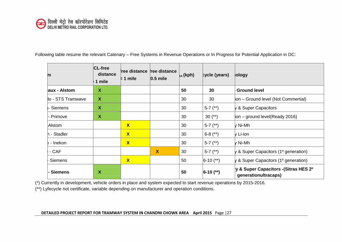
DETAILED PROJECT REPORT FOR TRAMWAY SYSTEM IN CHANDNI CHOWK AREA April 2015 Page |27
Following table resume the relevant Catenary – Free Systems in Revenue Operations or In Progress for Potential Application in DC:
System
OCL-free distance
> 1 mile
OCL-free distance
< 1 mile
OCL-free distance
<0.5 mile VMAX (kph) Lifecycle (years) Technology
Bordeaux - Alstom X 50 30 APS – Ground level
Ansaldo - STS Tramwave X 30 30 Induction – Ground level (Not Commertial)
Lisboa- Siemens X 30 5-7 (**) Battery & Super Capacitors
China - Primove X 30 30 (**) Induction – ground level(Ready 2016)
Nice - Alstom X 30 5-7 (**) Battery Ni-Mh
Munich - Stadler X 30 6-8 (**) Battery Li-ion
Seattle - Inekon X 30 5-7 (**) Battery Ni-Mh
Seville - CAF X 30 5-7 (**) Battery & Super Capacitors (1º generation)
Doha - Siemens X 50 6-10 (**) Battery & Super Capacitors (1º generation)
Qatar - Siemens X 50 6-10 (**) Battery & Super Capacitors -(Sitras HES 2º
generationultracaps)
(*) Currently in development, vehicle orders in place and system expected to start revenue operations by 2015-2016. (**) Lyfecycle not certificate, variable depending on manufacturer and operation conditions.
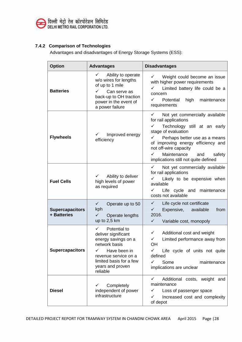
DETAILED PROJECT REPORT FOR TRAMWAY SYSTEM IN CHANDNI CHOWK AREA April 2015 Page |28
7.4.2 Comparison of Technologies Advantages and disadvantages of Energy Storage Systems (ESS):
Option Advantages Disadvantages
Batteries
Ability to operate w/o wires for lengths of up to 1 mile Can serve as back-up to OH traction power in the event of a power failure
Weight could become an issue with higher power requirements Limited battery life could be a concern Potential high maintenance requirements
Flywheels Improved energy efficiency
Not yet commercially available for rail applications Technology still at an early stage of evaluation Perhaps better use as a means of improving energy efficiency and not off-wire capacity Maintenance and safety implications still not quite defined
Fuel Cells Ability to deliver high levels of power as required
Not yet commercially available for rail applications Likely to be expensive when available Life cycle and maintenance costs not available
Supercapacitors + Batteries
Operate up to 50 kph Operate lengths up to 2,5 km
Life cycle not certificate Expensive, available from 2016. Variable cost, monopoly
Supercapacitors
Potential to deliver significant energy savings on a network basis Have been in revenue service on a limited basis for a few years and proven reliable
Additional cost and weight Limited performance away from OH Life cycle of units not quite defined Some maintenance implications are unclear
Diesel Completely independent of power infrastructure
Additional costs, weight and maintenance Loss of passenger space Increased cost and complexity of depot
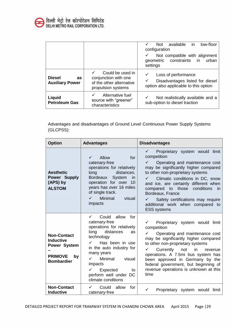
DETAILED PROJECT REPORT FOR TRAMWAY SYSTEM IN CHANDNI CHOWK AREA April 2015 Page |29
Not available in low-floor configuration Not compatible with alignment geometric constraints in urban settings
Diesel as Auxiliary Power
Could be used in conjunction with one of the other alternative propulsion systems
Loss of performance Disadvantages listed for diesel option also applicable to this option
Liquid Petroleum Gas
Alternative fuel source with “greener” characteristics
Not realistically available and a sub-option to diesel traction
Advantages and disadvantages of Ground Level Continuous Power Supply Systems (GLCPSS):
Option Advantages Disadvantages
Aesthetic Power Supply (APS) by ALSTOM
Allow for catenary-free operations for relatively long distances. Bordeaux System in operation for over 10 years has over 16 miles of single track. Minimal visual impacts
Proprietary system would limit competition Operating and maintenance cost may be significantly higher compared to other non-proprietary systems Climatic conditions in DC, snow and ice, are certainly different when compared to those conditions in Bordeaux, France Safety certifications may require additional work when compared to ESS systems
Non-Contact Inductive Power System – PRIMOVE by Bombardier
Could allow for catenary-free operations for relatively long distances as technology Has been in use in the auto industry for many years Minimal visual impacts Expected to perform well under DC climate conditions
Proprietary system would limit competition Operating and maintenance cost may be significantly higher compared to other non-proprietary systems Currently not in revenue operations. A 7.5mi bus system has been approved in Germany by the federal government, but beginning of revenue operations is unknown at this time
Non-Contact Inductive
Could allow for catenary-free Proprietary system would limit
DETAILED PROJECT REPORT FOR TRAMWAY SYSTEM IN CHANDNI CHOWK AREA April 2015 Page |30
Power system – STS by Ansaldo
operations for relatively long distances, given its similarities with the APS system noted above Minimal visual impacts
competition Operating and maintenance cost may be significantly higher compared to other non-proprietary systems Climatic conditions in DC, snow and ice, are certainly different when compared to those conditions in Bordeaux, France -Safety certifications may require additional work when compared to ESS systems
7.4.3 Wayside Impacts The wayside impacts associated with catenary-free technologies include the location
of electrical substation units and power distribution infrastructure elements required to provide the electrical power necessary to energize the system. These impacts are beyond the scope of this study and will need to be evaluated as part of future efforts of the project development process. It is important to note that most catenary-free systems use station areas to recharge ESS, such as batteries through the use of super capacitors or allow for recharging of battery packs at the ends of the line, accounting for longer periods for recharging of the ESS.
In either case, the station area is used to accommodate the necessary equipment for recharging of the system.
7.5 Conclusions Ground Level Continuous Power Supply Systems (APS systems) – This system is by
far the oldest system in operation around the world, with revenue operations over 10 years in Bordeaux, France. This is a proprietary system developed by ALSTOM and uses an in-ground contact rail/third rail, installed between the running rails, to distribute power and a shoe power collector on the vehicle. Electrical power is transmitted to the vehicle as the shoe collector makes contact with the power-rail. A loop detector installed on the vehicle allows only those segments of third-rail directly below the vehicle to be energized; thereby minimizing the risk for accidental contact between an electrified third-rail segment and pedestrians and/or any other objects.
This is certainly proven technology, given the years in revenue operation, however, special attention and careful evaluation of the proprietary implications, including O&M costs over the life of the asset, must be performed to determine its applicability to the DC Tramway Network. Equally important, weather conditions must be carefully evaluated to ensure that water logging and silting, do not create additional maintenance issues.
DETAILED PROJECT REPORT FOR TRAMWAY SYSTEM IN CHANDNI CHOWK AREA April 2015 Page |31
Inductive Systems
Similar to the APS system described above, inductive systems use a Ground Power Supply by either installing a third-rail between the running rails or other electrical hardware for contactless induction; however, unlike the APS system, inductive systems do not use a shoe collector, but rather rely on an electromagnetic field formed between the third-rail and a magnet on the vehicle to provide electrical power to the vehicle. This system is not currently in revenue operations. Similar to the APS system, this type of inductive system is proprietary and was developed by Ansaldo and Bombardier. Bombardier was recently awarded a contract in China for the construction of the first catenary-free system of its kind in that country, but revenue operations are not expected to begin until 2015-2016. Additional evaluations need to be conducted to confirm the applicability of this technology in the India.
Energy Storage Systems (ESS)
Including batteries and super capacitors, appear to have gained some popularity in Europe and today there are a few systems using these technologies. With this in mind, today ESS technologies offer a reliable catenary-free option and battery technology continues to improve, in many cases driven by the auto industry. Having said this, some concerns regarding overheating of batteries have been mitigated, but the history of systems using these technologies is somewhat limited. Therefore, ESS is certainly a technology that warrants further study, but careful evaluations of the subsystems must be performed to confirm applicability of this technology to the DC Tramway Network.
As noted in the executive summary included at the beginning of this report, the deployment strategy for the use of catenary-free technologies in DC need to take into account the following key items:
Implication of proprietary systems and subsystems, this is particularly important when considering warranty, operations and maintenance of the new system and vehicles. Ground Level Continuous Power Supply Systems are usually proprietary systems and could result in significantly higher costs over the life of the asset.
Technical Specifications and Procurement, the level of detail required to appropriately procure the right technology for the implementation of catenary-free operations needs to be such that appropriate performance criteria are clearly defined while allowing some room for flexibility and innovation, required to trigger a competitive bid setting without compromising the long-term benefits of the investment.
DETAILED PROJECT REPORT FOR TRAMWAY SYSTEM IN CHANDNI CHOWK AREA April 2015 Page |32
Utility Relocations, catenary-free technologies may significantly reduce the need for corrosion prone utility relocations as the potential for straycurrent leakage is minimal. This benefit would translate into significant infrastructure cost savings.
Wayside Infrastructure Requirements, irrespective of the technology, traction power substations would be required for any system. The location at the stations, power and distribution requirements associated with these units need to be evaluated to determine the infrastructure required for charging on-board systems or installation of a ground level continuous power supply.
Alignment Characteristics and Constraints, the technology selection is greatly dependent on the alignment characteristics and constraints, including horizontal and vertical geometry, as well as the availability of exclusive ROW. The maximum length of a catenary-free segment is a key driver in the selection of the right technology, with ESS having more limiting factors when compared to ground level systems. Similarly, shared lanes could present a problem for ESS applications as the storage capacity is limited to the type, size and number of storage devices (i.e., super capacitors, batteries, etc.) that can be accommodated on the vehicles. To that end, the ability to accurately predict running times between charging locations/stations is a key part of the ESS technology approach and the unpredictability of running shared lane operations could result in significant delays, thereby, compromising the reliability of this type of technology. Grades exceeding 7% could prove challenging for any technology as steeper grades would translate into much higher energy requirements.
Maximum Length of Catenary-Free Segment, based on the results of the data collection, there appears to be no limit to the maximum length for ground level systems as they use a ground level power-rail for power distribution. On the other hand, ESS technologies, based on the research of existing systems around the world, appear to have a maximum length in the range of ¼ mi- 2.5mi, contingent upon the specifics of the technology being used.
Vehicle Dimensions, the width and length of the vehicles are critical parts of the decision when selecting a catenary-free technology, given that storage space, either above or below the vehicle, would be limited when considering all other equipment needs, including HVAC. To that end, the Standard width of 2.46 m allows for much needed space for other equipment and energy storage devices. Similarly, a 20.13 m vehicle length would also allow for more storage space above and below the vehicle.
7.6 Traction Substations
Metro, tramway, light train; requires the supply of electric power with high standards of reliability. So, an important step in the development of these transportation systems is the electric power supply system planning and design.
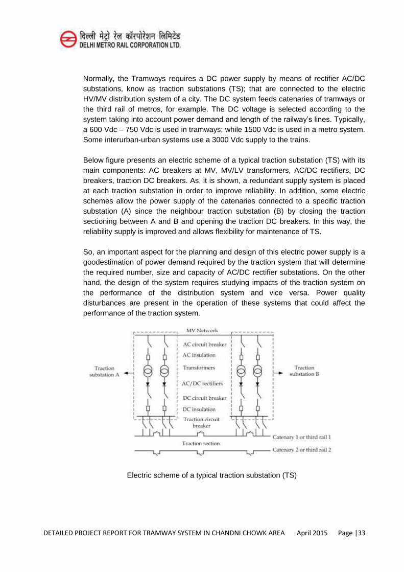
DETAILED PROJECT REPORT FOR TRAMWAY SYSTEM IN CHANDNI CHOWK AREA April 2015 Page |33
Normally, the Tramways requires a DC power supply by means of rectifier AC/DC substations, know as traction substations (TS); that are connected to the electric HV/MV distribution system of a city. The DC system feeds catenaries of tramways or the third rail of metros, for example. The DC voltage is selected according to the system taking into account power demand and length of the railway’s lines. Typically,
a 600 Vdc – 750 Vdc is used in tramways; while 1500 Vdc is used in a metro system. Some interurban-urban systems use a 3000 Vdc supply to the trains.
Below figure presents an electric scheme of a typical traction substation (TS) with its main components: AC breakers at MV, MV/LV transformers, AC/DC rectifiers, DC breakers, traction DC breakers. As, it is shown, a redundant supply system is placed at each traction substation in order to improve reliability. In addition, some electric schemes allow the power supply of the catenaries connected to a specific traction substation (A) since the neighbour traction substation (B) by closing the traction sectioning between A and B and opening the traction DC breakers. In this way, the reliability supply is improved and allows flexibility for maintenance of TS.
So, an important aspect for the planning and design of this electric power supply is a goodestimation of power demand required by the traction system that will determine the required number, size and capacity of AC/DC rectifier substations. On the other hand, the design of the system requires studying impacts of the traction system on the performance of the distribution system and vice versa. Power quality disturbances are present in the operation of these systems that could affect the performance of the traction system.
Electric scheme of a typical traction substation (TS)
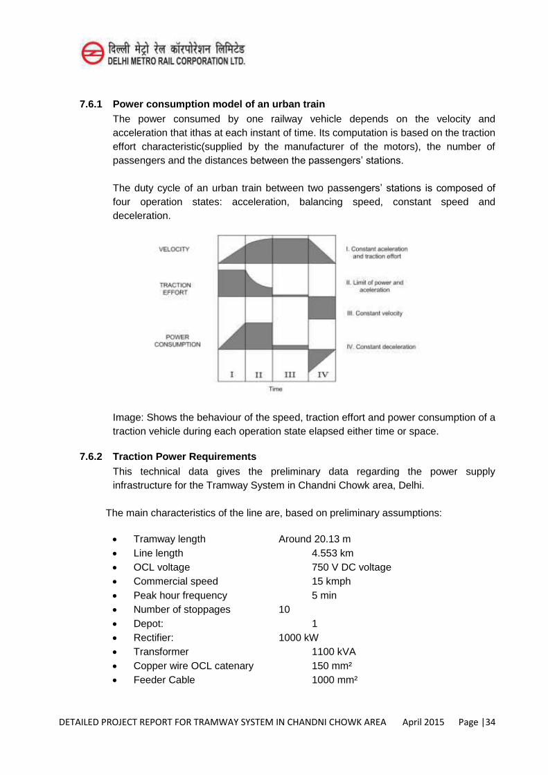
DETAILED PROJECT REPORT FOR TRAMWAY SYSTEM IN CHANDNI CHOWK AREA April 2015 Page |34
7.6.1 Power consumption model of an urban train The power consumed by one railway vehicle depends on the velocity and
acceleration that ithas at each instant of time. Its computation is based on the traction effort characteristic(supplied by the manufacturer of the motors), the number of passengers and the distances between the passengers’ stations.
The duty cycle of an urban train between two passengers’ stations is composed of four operation states: acceleration, balancing speed, constant speed and deceleration.
Image: Shows the behaviour of the speed, traction effort and power consumption of a traction vehicle during each operation state elapsed either time or space.
7.6.2 Traction Power Requirements This technical data gives the preliminary data regarding the power supply
infrastructure for the Tramway System in Chandni Chowk area, Delhi.
The main characteristics of the line are, based on preliminary assumptions:
Tramway length Around 20.13 m Line length 4.553 km OCL voltage 750 V DC voltage Commercial speed 15 kmph Peak hour frequency 5 min Number of stoppages 10 Depot: 1 Rectifier: 1000 kW Transformer 1100 kVA Copper wire OCL catenary 150 mm² Feeder Cable 1000 mm²
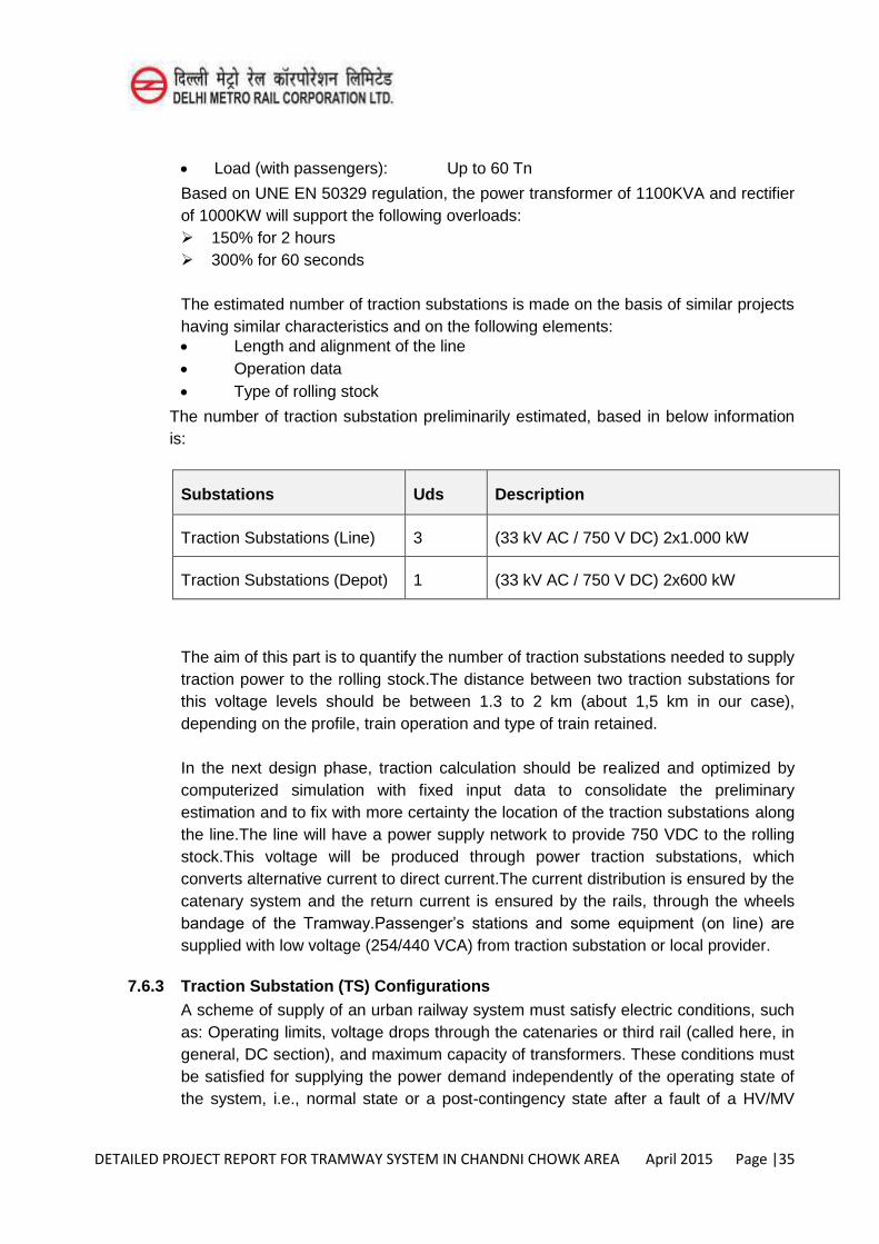
DETAILED PROJECT REPORT FOR TRAMWAY SYSTEM IN CHANDNI CHOWK AREA April 2015 Page |35
Load (with passengers): Up to 60 Tn
Based on UNE EN 50329 regulation, the power transformer of 1100KVA and rectifier of 1000KW will support the following overloads: 150% for 2 hours 300% for 60 seconds
The estimated number of traction substations is made on the basis of similar projects having similar characteristics and on the following elements: Length and alignment of the line Operation data Type of rolling stock
The number of traction substation preliminarily estimated, based in below information is:
Substations Uds Description
Traction Substations (Line) 3 (33 kV AC / 750 V DC) 2x1.000 kW
Traction Substations (Depot) 1 (33 kV AC / 750 V DC) 2x600 kW
The aim of this part is to quantify the number of traction substations needed to supply traction power to the rolling stock.The distance between two traction substations for this voltage levels should be between 1.3 to 2 km (about 1,5 km in our case), depending on the profile, train operation and type of train retained.
In the next design phase, traction calculation should be realized and optimized by computerized simulation with fixed input data to consolidate the preliminary estimation and to fix with more certainty the location of the traction substations along the line.The line will have a power supply network to provide 750 VDC to the rolling stock.This voltage will be produced through power traction substations, which converts alternative current to direct current.The current distribution is ensured by the catenary system and the return current is ensured by the rails, through the wheels bandage of the Tramway.Passenger’s stations and some equipment (on line) are
supplied with low voltage (254/440 VCA) from traction substation or local provider.
7.6.3 Traction Substation (TS) Configurations A scheme of supply of an urban railway system must satisfy electric conditions, such
as: Operating limits, voltage drops through the catenaries or third rail (called here, in general, DC section), and maximum capacity of transformers. These conditions must be satisfied for supplying the power demand independently of the operating state of the system, i.e., normal state or a post-contingency state after a fault of a HV/MV
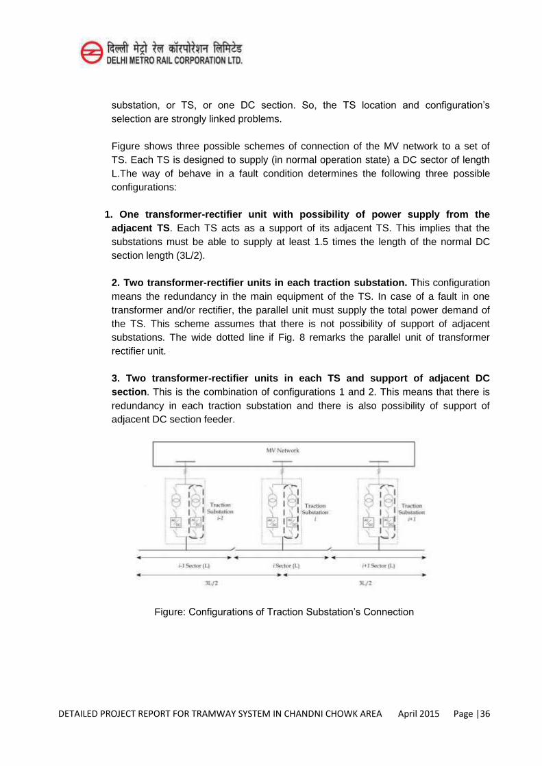
DETAILED PROJECT REPORT FOR TRAMWAY SYSTEM IN CHANDNI CHOWK AREA April 2015 Page |36
substation, or TS, or one DC section. So, the TS location and configuration’s
selection are strongly linked problems.
Figure shows three possible schemes of connection of the MV network to a set of TS. Each TS is designed to supply (in normal operation state) a DC sector of length L.The way of behave in a fault condition determines the following three possible configurations:
1. One transformer-rectifier unit with possibility of power supply from the adjacent TS. Each TS acts as a support of its adjacent TS. This implies that the substations must be able to supply at least 1.5 times the length of the normal DC section length (3L/2).
2. Two transformer-rectifier units in each traction substation. This configuration means the redundancy in the main equipment of the TS. In case of a fault in one transformer and/or rectifier, the parallel unit must supply the total power demand of the TS. This scheme assumes that there is not possibility of support of adjacent substations. The wide dotted line if Fig. 8 remarks the parallel unit of transformer rectifier unit.
3. Two transformer-rectifier units in each TS and support of adjacent DC section. This is the combination of configurations 1 and 2. This means that there is redundancy in each traction substation and there is also possibility of support of adjacent DC section feeder.
Figure: Configurations of Traction Substation’s Connection
DETAILED PROJECT REPORT FOR TRAMWAY SYSTEM IN CHANDNI CHOWK AREA April 2015 Page |37
7.6.4 Platform and tracks Along the platform runs a multitubular network (composed by sheaths) where power
and communication cables are installed. Depending on the configuration of the platform, the multitubular network can be central, side or double side.
The dimensions of the platform enable punctual traction power or power cables crossings (traction and LV).The structural characteristics of rail (including its resistivity) and the connection of two ways by negative equipotential bondings improve proper flow of current return.
7.6.5 Main issues associated with a 750 V DC feeding system The main advantages of the 750 VDC feeding mode for a Tramway line are:
Very commonly used all around the world 33 or 22 kV feeding for traction substations easily feasible Overhead Contact Line implementation highly feasible from an aesthetical
point of view.
With a line electrified in DC mode, some known problems can occur. These are mainly with:
Harmonics brought back into the Utilities network Rail/ground touchvoltage Straycurrents
Note: From a standard and technical point of view, 1.500 V DC electrification of a Tramway network is feasible, but the cost to develop a compliant rolling stock could lead to shorter bidder list.
7.6.6 Harmonics The connection of an electric installation of non-linear type (the rectifier of a traction
substation) on a distribution network will generate harmonic currents.
These harmonic currents are themselves also generating harmonic voltages and it is imperative that all new installations follow the utilities regulations. In order to avoid the installation of filters, the use of a 12-pulse rectifier is recommended rather than a 6-pulse rectifier1.
7.6.7 Rail/ground touch voltage Due to trams running and due to electrical isolation of the tracks, a voltage appears
between the rails and the ground. This voltage shall always be under 120 V (as a continuous value) and 60 V in workshops to be in conformity with EN 50 122-1 standard.
DETAILED PROJECT REPORT FOR TRAMWAY SYSTEM IN CHANDNI CHOWK AREA April 2015 Page |38
7.6.8 Stray Currents In DC railway electrical systems, rails are used to return the electrical current towards
the traction substations. The voltage drop in the rails can generate potential differences between the rails and the ground and current leakage into the ground. These extraneous currents flowing through soil and/or water, known as “stray
currents”, cause electrochemical corrosion damage to metal structures, or
reinforcement in contact with, or below ground. Low resistance between the traction return rails and the ground allows a significant part of the return current to leak into the ground.
Preventative and/ or corrective action can be taken to protect assets against the dangers of corrosion created by stray currents. The main methods for cathodic protection differ according to the type of structure that is affected by these stray currents. Corrective actions consist of installing drainage type or cathodic protective equipment. This type of protection is effective on metallic and continuous ducts which have a good electric conductivity.
7.6.9 Braking Energy Saving Nowadays tramways are equipped with braking energy saving. When braking,
motors become generators and the braking current is sent back on the Overhead Contact Line. In normal mode, the recovery rate could be between 20 to 30%.
We could try to recover more braking energy by using:
Inverter: extra braking energy is sent back to power utilities. Supercaps and batteries: installed in traction substations, they could stock a
part of the extra braking energy to give it back when a tram is in traction. This method is already used some Tramways systems around the globe.
Supercaps on-board: this is the optimum solution because there is no loss when the current flows through the OCS. Nevertheless this solution shall be implemented on each rolling stock unit.
7.6.10 Traction Substations Equipment 33 kV AC / 750 V DC Traction Substations concentrate HV equipment, Traction
equipment (transformation and distribution), LV equipment (transformation, distribution, electrical command).
The Traction power network will be used by the rolling stock.The LV power will provide electrical energy to the auxiliary equipment of the traction substation, passenger’s stations, operation room, signaling room, and some online equipment.
DETAILED PROJECT REPORT FOR TRAMWAY SYSTEM IN CHANDNI CHOWK AREA April 2015 Page |39
Traction substations can also accommodate other equipment such as signaling,transmission, video, etc.:
In traction substations with partitioning and separate access ; In adjacent room (to traction substations) such as signalling room or operation
room.
7.6.11 Standard Overhead Contact Line (OCL) The catenary could be made of one 150 mm² copper wire by track. To improve
current conduction, a connection with a large section cable is made regularly through paralleling cabinet.The position of the cabinet will be obtained by a simulation of traction sizing. These cabinets will be located on line and on stations.Additional positive equipotential bonding between the 2 wires of catenary will be positioned regularly.
7.6.12 Passenger’s station Passenger’s stations include equipment for their own power supply and occasionally
some equipment for the traction network.Power is supplied from traction substations or from the local provider through cabinets when the distances are too long.To be compliant with environmental and aesthetical constraints, electrical equipment of different users are grouped into technical cabinets integrated at the passenger’s
station
7.6.13 Traction Substation’s Architecture Typically, we find 2 types of architecture for traction substations for Metro and
Tramway Lines networks:
“π” traction substation with an up and down separation of the traction
substation, “T” traction substation with a direct link to the catenary.
Traction substations generally feed the line in parallel, which means that an electrical section could be fed by more than one traction substation. Then DC circuit-breakers need to have a secure interlocking by one with the other. Every DC circuit-breaker feeding the same electrical section shall be opened when one of them opens due to a short-circuit.
Both architectures are illustrated in the figures hereunder.
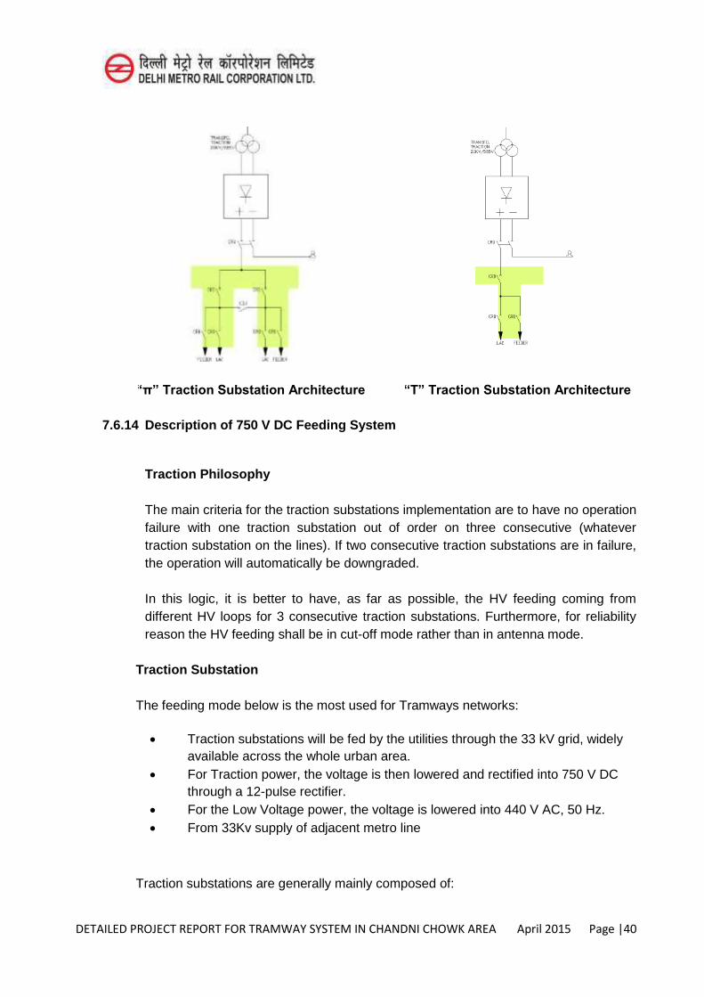
DETAILED PROJECT REPORT FOR TRAMWAY SYSTEM IN CHANDNI CHOWK AREA April 2015 Page |40
“π” Traction Substation Architecture “T” Traction Substation Architecture
7.6.14 Description of 750 V DC Feeding System
Traction Philosophy
The main criteria for the traction substations implementation are to have no operation failure with one traction substation out of order on three consecutive (whatever traction substation on the lines). If two consecutive traction substations are in failure, the operation will automatically be downgraded.
In this logic, it is better to have, as far as possible, the HV feeding coming from different HV loops for 3 consecutive traction substations. Furthermore, for reliability reason the HV feeding shall be in cut-off mode rather than in antenna mode.
Traction Substation
The feeding mode below is the most used for Tramways networks:
Traction substations will be fed by the utilities through the 33 kV grid, widely available across the whole urban area.
For Traction power, the voltage is then lowered and rectified into 750 V DC through a 12-pulse rectifier.
For the Low Voltage power, the voltage is lowered into 440 V AC, 50 Hz. From 33Kv supply of adjacent metro line
Traction substations are generally mainly composed of:
DETAILED PROJECT REPORT FOR TRAMWAY SYSTEM IN CHANDNI CHOWK AREA April 2015 Page |41
High Voltage
HV 33 kV incoming cells and HV protection cells. This equipment will be located in a separate room (if required by the power utilities) and connected to the utilities network in cut-off mode(preferable feeding mode for redundancy and then reliability reasons).
The availability of the 33 kV network has to be discussed locally.
Transformer and Rectifier group
One oil-type or dry transformers (the power will be defined later, (1100 kVA as a first approach).
One 12-pulse rectifiers (preferred to 6-pulse to lower harmonics in currents brought back to power utilities (1000 kW).
Traction distribution
High speed circuit breaker(s) and various switches and isolators to separate the Traction network if necessary.
Low Voltage and uninterruptible power system (UPS)
One dry transformers (the power will be defined later, (160 kVA as a first approach).
Uninterruptible power supply for sensible equipment, One low voltage switchgear for distributing power.
7.6.15 Depot The traction substation of the depot will supply power to the area of the depot and for
the line. That’s why the traction substation of the depot has two transformer and rectifier groups. Consequently, the size of the traction substation in the depot is larger than the other traction substations. It could mainly be identify as a double traction substation.
The traction substation of the depot is similar to an online traction substation. It has more
HV (33 kV) incoming cells and HV protection cells
One transformer One 12-pulse rectifiers
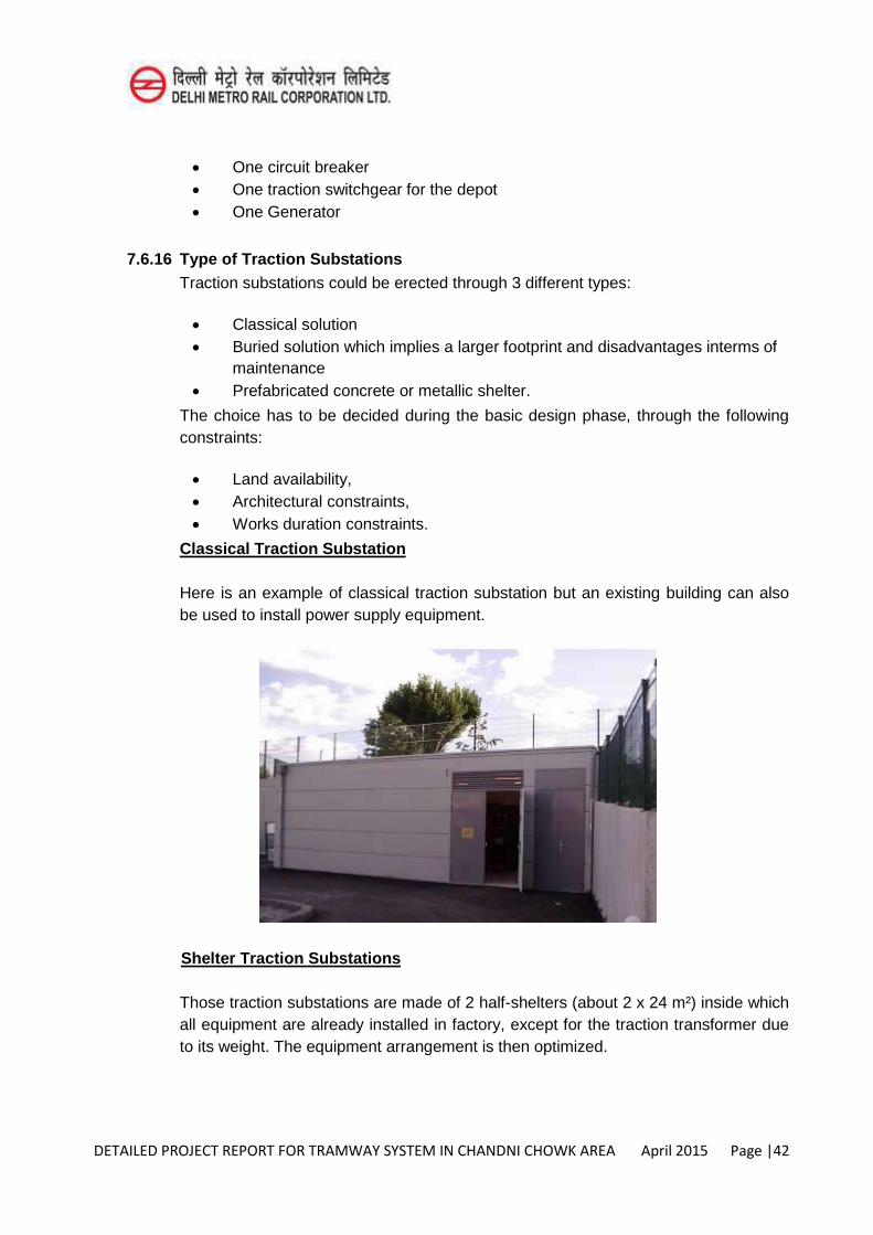
DETAILED PROJECT REPORT FOR TRAMWAY SYSTEM IN CHANDNI CHOWK AREA April 2015 Page |42
One circuit breaker One traction switchgear for the depot One Generator
7.6.16 Type of Traction Substations Traction substations could be erected through 3 different types:
Classical solution Buried solution which implies a larger footprint and disadvantages interms of
maintenance Prefabricated concrete or metallic shelter.
The choice has to be decided during the basic design phase, through the following constraints:
Land availability, Architectural constraints, Works duration constraints.
Classical Traction Substation
Here is an example of classical traction substation but an existing building can also be used to install power supply equipment.
Shelter Traction Substations
Those traction substations are made of 2 half-shelters (about 2 x 24 m²) inside which all equipment are already installed in factory, except for the traction transformer due to its weight. The equipment arrangement is then optimized.
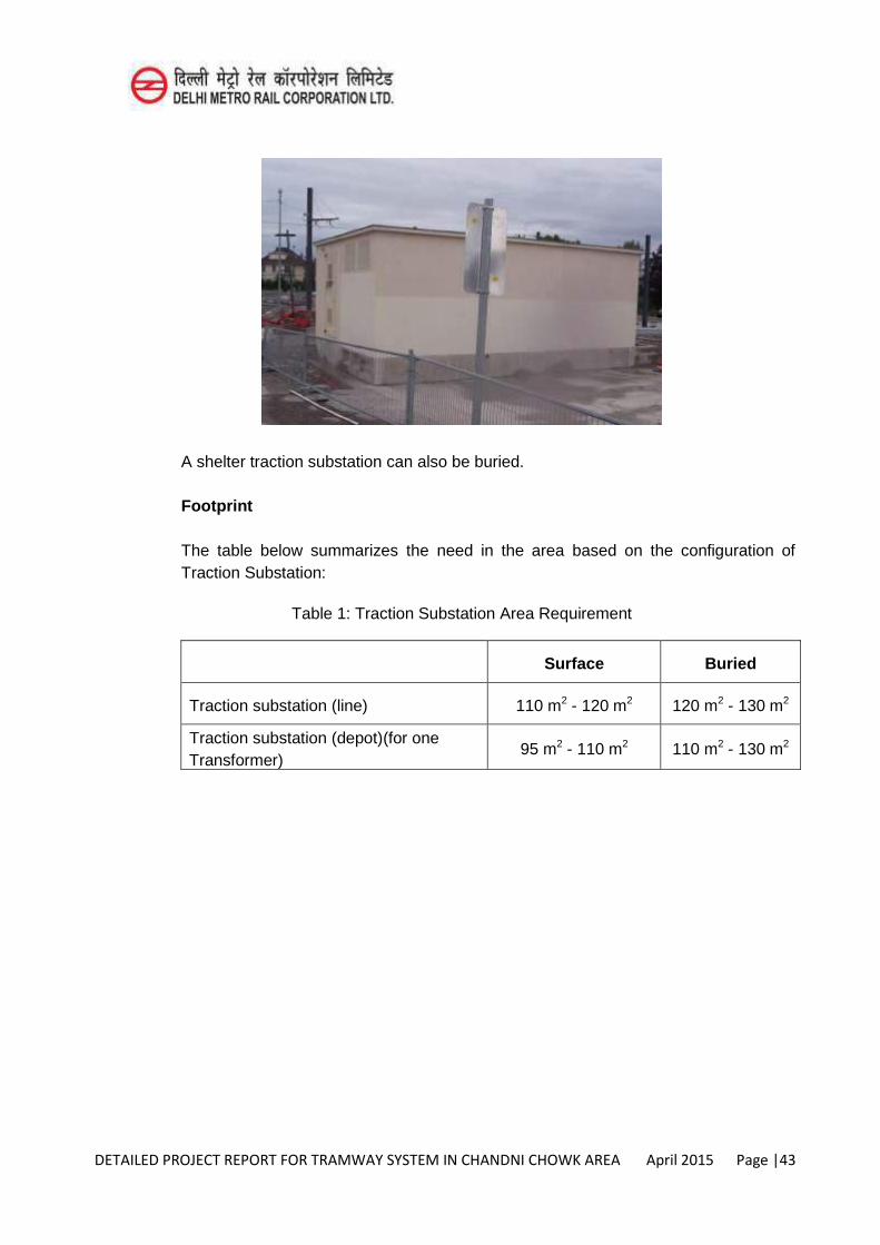
DETAILED PROJECT REPORT FOR TRAMWAY SYSTEM IN CHANDNI CHOWK AREA April 2015 Page |43
A shelter traction substation can also be buried.
Footprint
The table below summarizes the need in the area based on the configuration of Traction Substation:
Table 1: Traction Substation Area Requirement
Surface Buried
Traction substation (line) 110 m2 - 120 m2 120 m2 - 130 m2
Traction substation (depot)(for one Transformer)
95 m2 - 110 m2 110 m2 - 130 m2
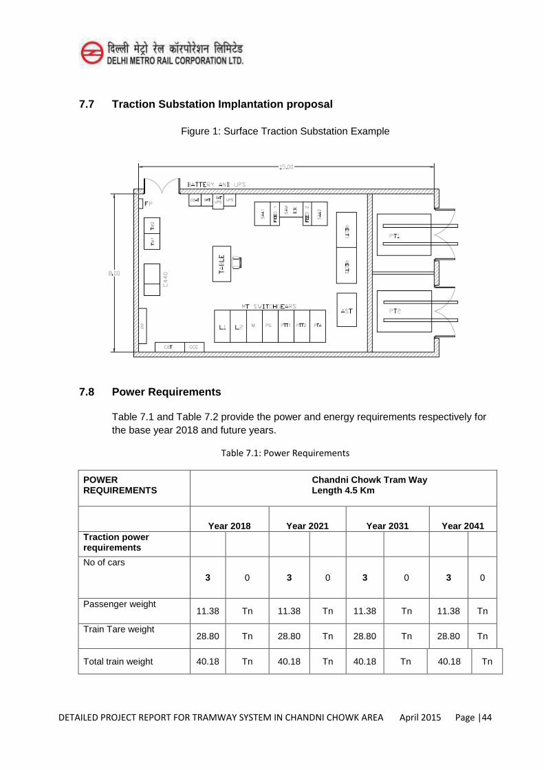
DETAILED PROJECT REPORT FOR TRAMWAY SYSTEM IN CHANDNI CHOWK AREA April 2015 Page |44
7.7 Traction Substation Implantation proposal
Figure 1: Surface Traction Substation Example
7.8 Power Requirements
Table 7.1 and Table 7.2 provide the power and energy requirements respectively for the base year 2018 and future years.
Table 7.1: Power Requirements
POWER REQUIREMENTS
Chandni Chowk Tram Way Length 4.5 Km
Year 2018 Year 2021 Year 2031 Year 2041 Traction power requirements
No of cars
3 0 3 0 3 0 3 0
Passenger weight 11.38 Tn 11.38 Tn 11.38 Tn 11.38 Tn
Train Tare weight 28.80 Tn 28.80 Tn 28.80 Tn 28.80 Tn
Total train weight 40.18 Tn 40.18 Tn 40.18 Tn 40.18 Tn
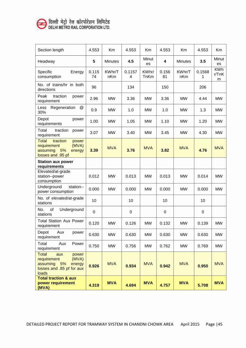
DETAILED PROJECT REPORT FOR TRAMWAY SYSTEM IN CHANDNI CHOWK AREA April 2015 Page |45
Section length 4.553 Km 4.553 Km 4.553 Km 4.553 Km
Headway 5 Minutes 4.5 Minutes
4 Minutes 3.5 Minutes
Specific Energy consumption
0.11574
KWhr/TnKm
0.11574
KWhr/TnKm
0.15681
KWhr/TnKm
0.15681
KWhr/TnK
m No. of trains/hr in both directions
96 134 150 206
Peak traction power requirement 2.96 MW 3.36 MW 3.36 MW 4.44 MW
Less Regeneration @ 30%
0.9 MW 1.0 MW 1.0 MW 1.3 MW
Depot power requirements
1.00 MW 1.05 MW 1.10 MW 1.20 MW
Total traction power requirement
3.07 MW 3.40 MW 3.45 MW 4.30 MW
Total traction power requirement (MVA) assuming 5% energy losses and .95 pf
3.39 MVA
3.76 MVA
3.82 MVA
4.76 MVA
Station aux power requirements
Elevated/at-grade station--power consumption
0.012 MW 0.013 MW 0.013 MW 0.014 MW
Underground station--power consumption
0.000 MW 0.000 MW 0.000 MW 0.000 MW
No. of elevated/at-grade stations
10 10 10 10
No. of Underground stations
0 0 0 0
Total Station Aux Power requirement
0.120 MW 0.126 MW 0.132 MW 0.139 MW
Depot Aux power requirement
0.630 MW 0.630 MW 0.630 MW 0.630 MW
Total Aux Power requirement
0.750 MW 0.756 MW 0.762 MW 0.769 MW
Total aux power requirement (MVA) assuming 5% energy losses and .85 pf for aux loads
0.926 MVA
0.934 MVA
0.942 MVA
0.950 MVA
Total traction & aux power requirement (MVA)
4.319 MVA
4.694 MVA 4.757 MVA
5.708 MVA
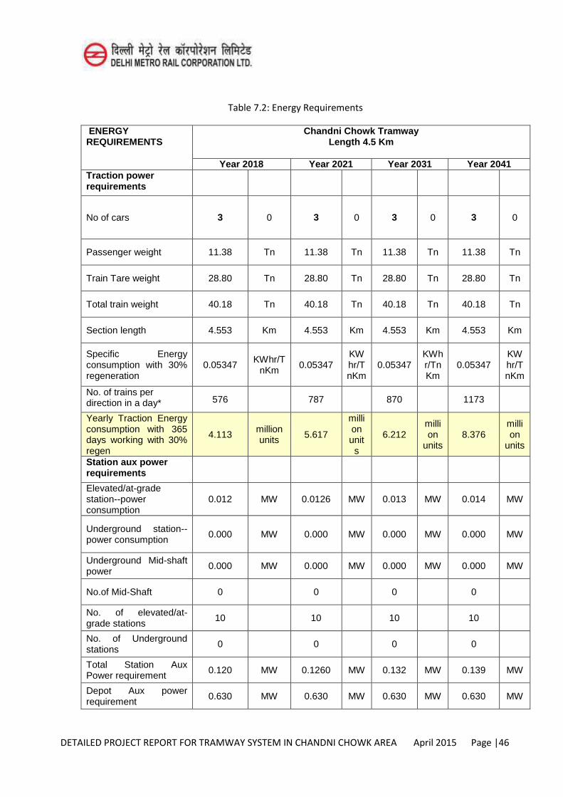
DETAILED PROJECT REPORT FOR TRAMWAY SYSTEM IN CHANDNI CHOWK AREA April 2015 Page |46
Table 7.2: Energy Requirements
ENERGY REQUIREMENTS
Chandni Chowk Tramway Length 4.5 Km
Year 2018 Year 2021 Year 2031 Year 2041 Traction power requirements
No of cars 3 0 3 0 3 0 3 0
Passenger weight 11.38 Tn 11.38 Tn 11.38 Tn 11.38 Tn
Train Tare weight 28.80 Tn 28.80 Tn 28.80 Tn 28.80 Tn
Total train weight 40.18 Tn 40.18 Tn 40.18 Tn 40.18 Tn
Section length 4.553 Km 4.553 Km 4.553 Km 4.553 Km
Specific Energy consumption with 30% regeneration
0.05347 KWhr/T
nKm 0.05347
KWhr/TnKm
0.05347 KWhr/TnKm
0.05347 KWhr/TnKm
No. of trains per direction in a day* 576 787 870 1173
Yearly Traction Energy consumption with 365 days working with 30% regen
4.113 million units 5.617
million units
6.212 million
units 8.376
million
units
Station aux power requirements
Elevated/at-grade station--power consumption
0.012 MW 0.0126 MW 0.013 MW 0.014 MW
Underground station--power consumption
0.000 MW 0.000 MW 0.000 MW 0.000 MW
Underground Mid-shaft power
0.000 MW 0.000 MW 0.000 MW 0.000 MW
No.of Mid-Shaft 0 0 0 0
No. of elevated/at-grade stations
10 10 10 10
No. of Underground stations
0 0 0 0
Total Station Aux Power requirement 0.120 MW 0.1260 MW 0.132 MW 0.139 MW
Depot Aux power requirement 0.630 MW 0.630 MW 0.630 MW 0.630 MW
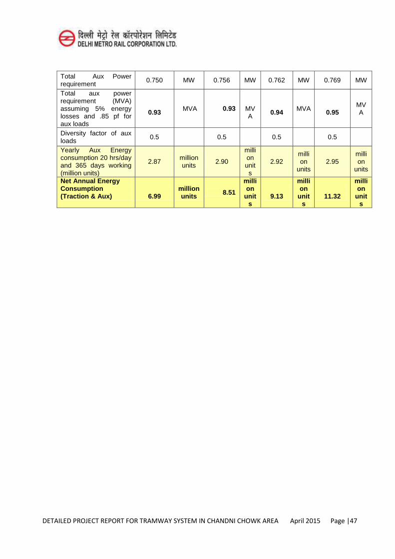
DETAILED PROJECT REPORT FOR TRAMWAY SYSTEM IN CHANDNI CHOWK AREA April 2015 Page |47
Total Aux Power requirement
0.750 MW 0.756 MW 0.762 MW 0.769 MW
Total aux power requirement (MVA) assuming 5% energy losses and .85 pf for aux loads
0.93 MVA 0.93
MVA
0.94 MVA
0.95
MVA
Diversity factor of aux loads
0.5 0.5 0.5 0.5
Yearly Aux Energy consumption 20 hrs/day and 365 days working (million units)
2.87 million units
2.90
million units
2.92 million
units 2.95
million
units
Net Annual Energy Consumption (Traction & Aux)
6.99
million units 8.51
million
units
9.13
million
units
11.32
million
units
DETAILED PROJECT REPORT FOR TRAMWAY SYSTEM IN CHANDNI CHOWK AREA April 2015 Page |1
CHAPTER-8
MAINTENANCE DEPOT
8.1 Introduction
A major operational component of a tramway system is the system depot, maintenance facility and administration building, including the system’s operations
control centre (OCC). The system is not able to operate without such facilities. The functional requirements and potential depot locations of the system are detailed below.
8.2 Operational Requirements
The following operational requirements must be consider in selecting a depot site:
Proximity Type and proximity of surrounding land uses Vehicular access to the depot area Environmental impacts Depot layout Shape and size of available plot of land Stabling requirements Minimising dead mileage at the start and end of the scheduled operations Minimising impact on main line operations Safety and security
8.3 Proximity to the System
A key consideration for the location of the tramway depot is its distance to the Loop Corridor. This distance affects:
Capital costs in providing access to the system Capital cost in supporting infrastructure including the communication system Operational cost related to travel distance and time to and from the depot Minimize response time in case of an incident (vehicles broken down or
defective, infrastructure failure or damaged, etc.) Overall system security
DETAILED PROJECT REPORT FOR TRAMWAY SYSTEM IN CHANDNI CHOWK AREA April 2015 Page |2
8.4 Surrounding Land Uses
As the depot, maintenance and administration facility will operate 24 hours per day, 7 day a week, the impact of the depot operations on surrounding land uses is a main factor to be considered.
Ideally, the depot should be located in an industrial or commercial area. Location within or close to residential areas are less appropriate and may require additional remedial measures to mitigate impacts such as traffic, noise and visual amenity.
8.5 Vehicle Access to Depot
The operational nature of the tramway system will require 24-hour road access to the mainline track and to the depot area for suppliers’ and staff vehicles. This includes vehicles delivering spares and components. A list of expected vehicles is listed below:
Operational staff and crewvehicles
Maintenance and Safety system officer vehicles
Deliver vehicles for spare parts, fuel
Over-size vehicles for the delivery and removal of heavy equipment including
traction, power substation equipment, etc.
Emergency services vehicles in times of incident management
The location of the depot should minimise dead mileage at the commencement and completion of scheduled operations and the access to the depot should be as close as possible to the Loop Corridor.
8.6 Operational Environmental Impacts
The following environmental impacts during construction and operations should be considered and mitigation measures designed. This includes:
Noise impacts
Storm wáter quality impacts
Safe storage of combustible and hazardous materials (fuels, gases, paint,
solvents, hydraulic and lubricants, etc.)
Polluted soils
Electromagnetic radiation
Impacts on flora and fauna
DETAILED PROJECT REPORT FOR TRAMWAY SYSTEM IN CHANDNI CHOWK AREA April 2015 Page |3
8.7 Shape and size of available sites
The shape and size of available plot of land, combined with the tramway geometric design requirements fundamentally influences the layout of the depot. Large, flat sites without spatially constrains vehicles movements or limit capacity are preferred.
8.8 Stabling requirements
Ideally, stabling for the fleet should be provided at the depot site. This assists in operational efficiency in driver access and overall system security. Given that the tramway fleet size will vary over the life of the system, provision for initial and future stabling should be considered, including likely changes in tramway vehicles length.
The total fleet length of the system has been used to assess the amount of land required for the depot operation. The available of a suitable area of land for vehicle stabling is a key issue for the depot selection.
8.9 Depot and stabling layout
The depot layout should be developed to allow moving tramway vehicles efficiently between any stabling and depot facilities within minimal shunting required. It must take into consideration the signalling requirements for safe tramway vehicles movements and flexible manoeuvrability for day-to-day operations.
8.10 Depot Operational Requirements
The following operational facilities are required at the depot.
8.10.1 Tramway fleet maintenance building
Summer weather conditions in Delhi (high temperatures, high humidity, heavy monsoon rains and mosquitos plagues) recommend tramway vehicles built for both light and heavy maintenance tasks. It needs to guarantee an adequate maintaining level of the fleet. Typically tramway maintenance facilities allow a full tramway vehicle to enter a weatherproof maintenance building, either by using a jacking system, raised track or below track inspection pits to enable maintenance staff to access the underside of the tramway car.
8.10.2 On-site parking requirements
Off-street staff parking for all management, administration, maintenance and one full shift of operational staff needs to be provided.
DETAILED PROJECT REPORT FOR TRAMWAY SYSTEM IN CHANDNI CHOWK AREA April 2015 Page |4
8.11 Depot Sizing Requirements
The transport modelling for the Chandni Chowk tramway system has determined the required initial capacity during the peak hour of about 2,000-4,000 passenger/hr and may be expanded in a future. An initial fleet size of 8 cars plus 2 for spares and maintenance has been proposed. Additional extensions of the system may place additional stabling demand on the depot site.
The land area required for the stabling and maintenance has been based on the total length of vehicles for the system. Based on the operational scenario, the total length of the fleet will be 201.3m assuming a 20.13 m long vehicle. The proposed depot size is about 20.000 m2.
8.12 Maintenance building
According the Light Railway Trains planning guidelines provided by the International Association of Public Transport (UIPT):
The length of the building should be twice that of the maximum length of a single vehicle so as to allow for 2 cars to be housed on the same pit track, plus walkways and clearance on both ends of the building.
The width is determined by the number of vehicle berths and pit tracks The distance between the pit track centres inside the building should be at least
6 m, which allows enough space between two vehicles on adjacent tracks for moving forklifts and other equipment/machinery.
In this case, the maintenance building has been assumed to have an initial length of 50 m and a width of 30 m. This allows 5 tracks, with an adjacent building for ancillary workshops, stores, staff rooms, etc.
8.13 Recommended Depot site
An ideal site has been identified in the south of the tramway Corridor. It is bounded by Patel Gali Road and Netaji Subhash Marg as shown in Figure 1. The site is currently a DDA park.
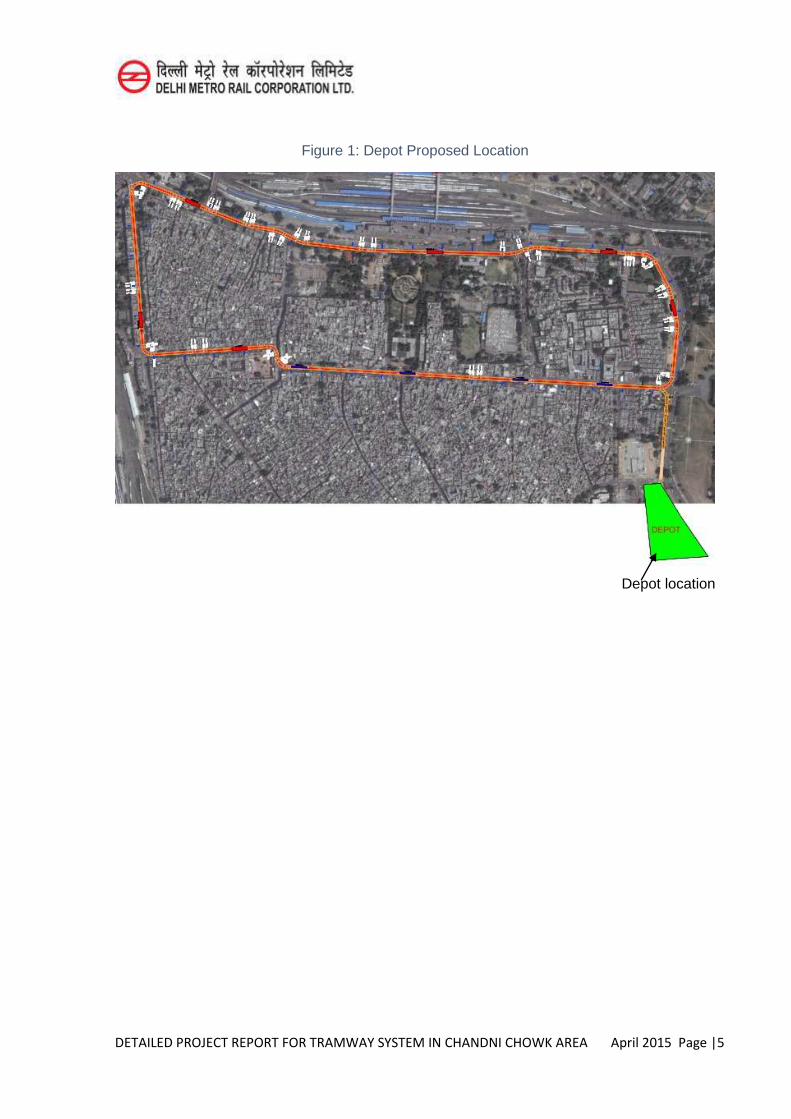
DETAILED PROJECT REPORT FOR TRAMWAY SYSTEM IN CHANDNI CHOWK AREA April 2015 Page |5
Figure 1: Depot Proposed Location
Depot location
DETAILED PROJECT REPORT FOR TRAMWAY SYSTEM IN CHANDNI CHOWK AREA April 2015 Page |1
CHAPTER-9
ENVIRONMENT AND SOCIAL IMPACT ASSESSMENT
9.1 INTRODUCTION
Chandni Chowk is a part of walled city. This is an heritage area having many historical places all around. Delhi's tram system opened on 6 March 1908. At its zenith in 1921 there were 24 open cars utilising 15 km of track. The system was in operation until 1963. The proposed Tram-line is expected to be of 4.5 kms in length, which will run in a loop in the Chandni Chowk area. It will take approximately 18 minutes to complete the entire length. It has 10 stops which varies to a distance of 240 metres to 830 meters depending on the stretch where the tram is running. It is expected that the ridership of the proposed tram will be 41,545 people.
9.1.1 Approach and Methodology
The suggestive method is based on Technical Feasibility, Socio-economic acceptability, and Environmental sustainability of Tramways. The environmental study is carried out for the proposed alignment. The parameters for the baseline data are physical, ecological and environmental. The impacts are assessed for various phases of project cycle. The impacts are categorized as negative and positive. The cost of management and monitoring programs are estimated and budgeted
9.1.2 Reintroduction of Tramway
Historically, Chandni Chowk was having tramway which was operational till 1963. It has been planned to reintroduce the tramway system in Chandni Chowk to revive the heritage and to decongest the market places like Chandni Chowk, Khari Baoli, Naya Bazaar Road and to integrate the tramway with Railway station and Bus stops connecting the market place directly with satellite towns and all other parts of Delhi.
9.2 ENVIRONMENTAL BASELINE DATA
9.2.1 Objective of Environmental Impact Assessment
The objective of Environmental Impact Assessment (EIA) is to ascertain the baseline environmental conditions and assess the impacts as a result of the proposed project during various phases of the project cycle.
DETAILED PROJECT REPORT FOR TRAMWAY SYSTEM IN CHANDNI CHOWK AREA April 2015 Page |2
9.2.2 Land Environment
The Project area is situated in Chandni Chowk Area.. The average elevation of the project area is ranging between 216 - 227 m above the sea level (a-MSL). Parameters involved in land environment are, physiography, geology and soils, and seismicity. These are detailed in the following paragraphs.
Physiography
The physiography of Chandni Chowk is dominated by the river Yamuna, The average gradient is gentle.
Geology and Soils
The area under study is part of the Yamuna Basin comprising the newer alluvium made up of fine to medium sand, silts, gravel, clay and kankar. The surface belts are admixed with wind-blown sediments or recent age. These alluvial sediments are known to be underlined by hard formations of Delhi system of rocks. Following is the general sequence of formations met with in the area:
Recent to Sub – Recent : Alluvium
Post-Delhi Intrusive : Pegmatic and basic intrusive
Algonkian (Delhi System) : Alwar Quartzites
Seismicity
The country has been classified into different zones indicating the intensity of damage or frequency of earthquake occurrences. Chandni Chowk, Delhi is located in zone IV of seismic zoning map of India (Figure 9.1). The zone has fairly high seismicity with general occurrence of earthquakes of 5-6 magnitude, a few of magnitude 6-7 and occasionally of 7-8 magnitude.Delhi thus lies among the high-risk areas. Seismicity in an around Delhi appears to be associated with a major geological structure, known as the Delhi-Haridwar Ridge. This ridge constitutes an important tectonic block between 28O - 30O N and 76O - 79 O E with a NE-SW trend. The first recorded major earthquake in this region occurred on 15th July 1720 of intensity 9.0. Subsequent other earthquake events occurred in 1803, 1819, 19005, 1934, 1937, 1945, 1949, 1958, 1960, 1966, 1975, 1980, 1994, of intensity between 7.0 to 9.0.
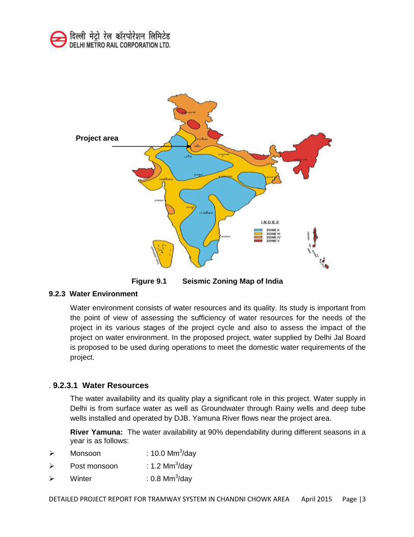
DETAILED PROJECT REPORT FOR TRAMWAY SYSTEM IN CHANDNI CHOWK AREA April 2015 Page |3
Project area
Figure 9.1 Seismic Zoning Map of India
9.2.3 Water Environment
Water environment consists of water resources and its quality. Its study is important from the point of view of assessing the sufficiency of water resources for the needs of the project in its various stages of the project cycle and also to assess the impact of the project on water environment. In the proposed project, water supplied by Delhi Jal Board is proposed to be used during operations to meet the domestic water requirements of the project.
. 9.2.3.1 Water Resources
The water availability and its quality play a significant role in this project. Water supply in Delhi is from surface water as well as Groundwater through Rainy wells and deep tube wells installed and operated by DJB. Yamuna River flows near the project area.
River Yamuna: The water availability at 90% dependability during different seasons in a year is as follows:
Monsoon : 10.0 Mm3/day
Post monsoon : 1.2 Mm3/day
Winter : 0.8 Mm3/day
DETAILED PROJECT REPORT FOR TRAMWAY SYSTEM IN CHANDNI CHOWK AREA April 2015 Page |4
Summer : 0.1 Mm3/day
Rainwater: The annual normal rainfall of the area is 792.4 mm as observed in the nearest IMD rain gauge station at Okhla. The maximum rainfall occurs during the monsoon period i.e., June to September having the normal value of 700.3mm .The same is 88.38% of annual rainfall.
9.2.3.2 Ground Water
Ground water occur under Phreatic conditions in shallow aquifers down to the depth of 100 m below ground level, in intermediate and deeper aquifers it occurs under confined to semi-confined conditions. Near project site depth to water table varies upto 14m.
9.2.4 Meteorology
The climate of this area is mainly influenced by its geographical inland position and the prevalence of air of the continental type during the major part of the year. Extreme dryness with an immensely hot summer and cold winter is the characteristics of the climate. During the three monsoon months of July, August and September, the air of oceanic origin blows over this area and increase the humidity, cloudiness and precipitation. The year can broadly be classified into four seasons. The cold season starts in late November and extends to the beginning of March. This is followed by the summer season, which lasts till the end of June. The Monsoon season continues till the last week of September. The two post-monsoon months, October and November, constitute a transition period from the monsoon to the winter season.
9.2.5 Air Environment
Delhi, in terms of air pollution, is ranked among the most polluted areas in the world. The atmospheric concentrations of air pollutants were monitored at 2 locations near the proposed alignment during the months of February 2015. Locations of air monitoring station are shown in Figure 9.2. Air Monitoring was carried out for PM10, NOx and SO2.
Results of the air quality monitoring are presented in Table 9.1
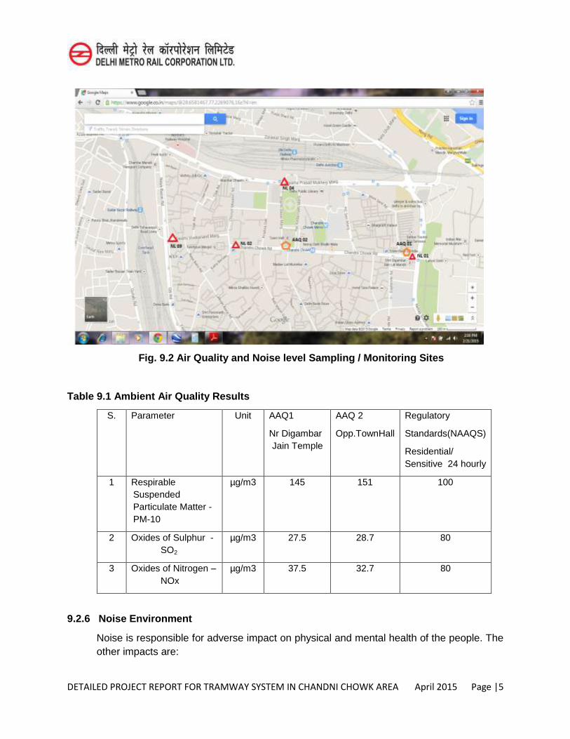
DETAILED PROJECT REPORT FOR TRAMWAY SYSTEM IN CHANDNI CHOWK AREA April 2015 Page |5
Fig. 9.2 Air Quality and Noise level Sampling / Monitoring Sites
Table 9.1 Ambient Air Quality Results
S. No.
Parameter Unit AAQ1
Nr Digambar Jain Temple
AAQ 2
Opp.TownHall
Regulatory
Standards(NAAQS)
Residential/ Sensitive 24 hourly
1 Respirable Suspended Particulate Matter - PM-10
µg/m3 145 151 100
2 Oxides of Sulphur - SO2
µg/m3 27.5 28.7 80
3 Oxides of Nitrogen – NOx
µg/m3 37.5 32.7 80
9.2.6 Noise Environment
Noise is responsible for adverse impact on physical and mental health of the people. The other impacts are:
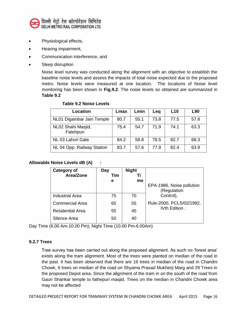
DETAILED PROJECT REPORT FOR TRAMWAY SYSTEM IN CHANDNI CHOWK AREA April 2015 Page |6
Physiological effects,
Hearing impairment,
Communication interference, and
Sleep disruption
Noise level survey was conducted along the alignment with an objective to establish the baseline noise levels and assess the impacts of total noise expected due to the proposed metro. Noise levels were measured at one location. The locations of Noise level monitoring has been shown in Fig.9.2. The noise levels so obtained are summarized in Table 9.2
Table 9.2 Noise Levels
Location Lmax Lmin Leq L10 L90
NL01 Digambar Jain Temple 80.7 55.1 73.8 77.5 57.8
NL02 Shahi Masjid, Fatehpuri
75.4 54.7 71.9 74.1 63.3
NL 03 Lahori Gate 84.2 58.8 78.5 82.7 68.3
NL 04 Opp. Railway Station 83.7 57.6 77.9 82.4 63.9
Allowable Noise Levels dB (A) :
Category of Area/Zone
Day Time
Night Time
EPA-1986, Noise pollution (Regulation Control),
Rule-2000, PCLS/02/1992, IVth Edition .
Industrial Area
Commercial Area
Residential Area
Silence Area
75
65
55
50
70
55
45
40
Day Time (6.00 Am-10.00 Pm); Night Time (10.00 Pm-6.00Am)
9.2.7 Trees
Tree survey has been carried out along the proposed alignment. As such no ‘forest area’
exists along the tram alignment. Most of the trees were planted on median of the road in the past. It has been observed that there are 16 trees in median of the road in Chandni Chowk, 6 trees on median of the road on Shyama Prasad Mukherji Marg and 29 Trees in the proposed Depot area. Since the alignment of the tram in on the south of the road from Gauri Shankar temple to fathepuri masjid. Trees on the median in Chandni Chowk area may not be affected
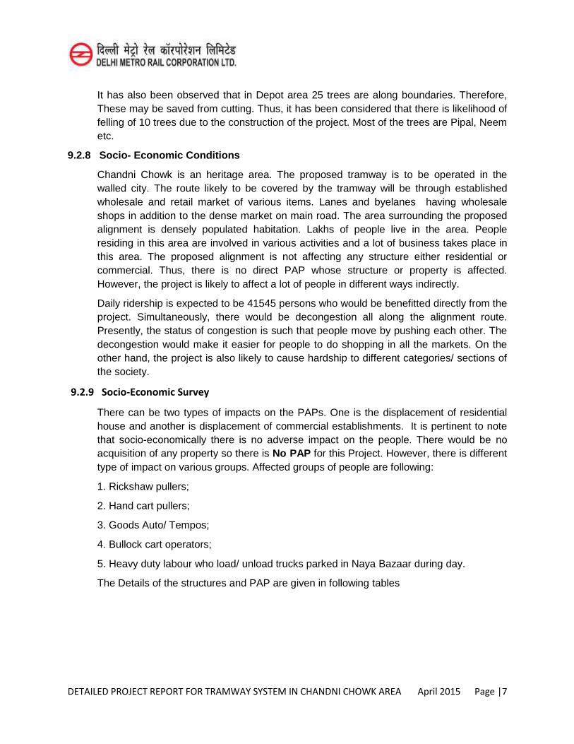
DETAILED PROJECT REPORT FOR TRAMWAY SYSTEM IN CHANDNI CHOWK AREA April 2015 Page |7
It has also been observed that in Depot area 25 trees are along boundaries. Therefore, These may be saved from cutting. Thus, it has been considered that there is likelihood of felling of 10 trees due to the construction of the project. Most of the trees are Pipal, Neem etc.
9.2.8 Socio- Economic Conditions
Chandni Chowk is an heritage area. The proposed tramway is to be operated in the walled city. The route likely to be covered by the tramway will be through established wholesale and retail market of various items. Lanes and byelanes having wholesale shops in addition to the dense market on main road. The area surrounding the proposed alignment is densely populated habitation. Lakhs of people live in the area. People residing in this area are involved in various activities and a lot of business takes place in this area. The proposed alignment is not affecting any structure either residential or commercial. Thus, there is no direct PAP whose structure or property is affected. However, the project is likely to affect a lot of people in different ways indirectly.
Daily ridership is expected to be 41545 persons who would be benefitted directly from the project. Simultaneously, there would be decongestion all along the alignment route. Presently, the status of congestion is such that people move by pushing each other. The decongestion would make it easier for people to do shopping in all the markets. On the other hand, the project is also likely to cause hardship to different categories/ sections of the society.
9.2.9 Socio-Economic Survey
There can be two types of impacts on the PAPs. One is the displacement of residential house and another is displacement of commercial establishments. It is pertinent to note that socio-economically there is no adverse impact on the people. There would be no acquisition of any property so there is No PAP for this Project. However, there is different type of impact on various groups. Affected groups of people are following:
1. Rickshaw pullers;
2. Hand cart pullers;
3. Goods Auto/ Tempos;
4. Bullock cart operators;
5. Heavy duty labour who load/ unload trucks parked in Naya Bazaar during day.
The Details of the structures and PAP are given in following tables
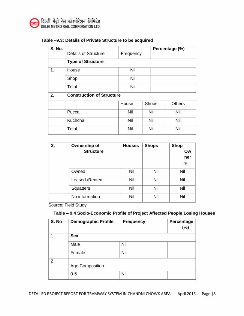
DETAILED PROJECT REPORT FOR TRAMWAY SYSTEM IN CHANDNI CHOWK AREA April 2015 Page |8
Table –9.3: Details of Private Structure to be acquired
S. No. Details of Structure Frequency
Percentage (%)
Type of Structure
1. House Nil
Shop Nil
Total Nil
2. Construction of Structure
House Shops Others
Pucca Nil Nil Nil
Kuchcha Nil Nil Nil
Total Nil Nil Nil
3. Ownership of Structure
Houses Shops Shop Owners
Owned Nil Nil Nil
Leased /Rented Nil Nil Nil
Squatters Nil Nil Nil
No information Nil Nil Nil
Source: Field Study
Table – 9.4 Socio-Economic Profile of Project Affected People Losing Houses
S. No Demographic Profile Frequency Percentage (%)
1 Sex
Male Nil
Female Nil
2 Age Composition
0-6 Nil
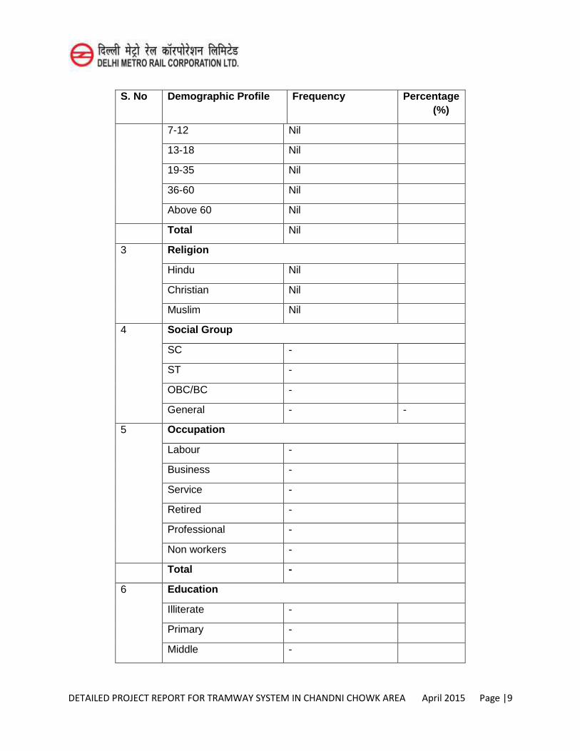
DETAILED PROJECT REPORT FOR TRAMWAY SYSTEM IN CHANDNI CHOWK AREA April 2015 Page |9
S. No Demographic Profile Frequency Percentage (%)
7-12 Nil
13-18 Nil
19-35 Nil
36-60 Nil
Above 60 Nil
Total Nil
3 Religion
Hindu Nil
Christian Nil
Muslim Nil
4 Social Group
SC -
ST -
OBC/BC -
General - -
5 Occupation
Labour -
Business -
Service -
Retired -
Professional -
Non workers -
Total -
6 Education
Illiterate -
Primary -
Middle -
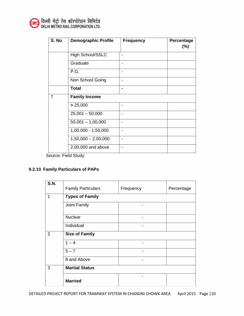
DETAILED PROJECT REPORT FOR TRAMWAY SYSTEM IN CHANDNI CHOWK AREA April 2015 Page |10
S. No Demographic Profile Frequency Percentage (%)
High School/SSLC -
Graduate -
P.G. -
Non School Going -
Total -
7 Family Income
> 25,000 -
25,001 – 50,000 -
50,001 – 1,00,000 -
1,00,000 - 1,50,000 -
1,50,000 – 2,00,000 -
2,00,000 and above -
Source: Field Study
9.2.10 Family Particulars of PAPs
S.N. Family Particulars Frequency Percentage
1 Types of Family
Joint Family -
Nuclear -
Individual -
2 Size of Family
1 – 4 -
5 – 7 -
8 and Above -
3 Marital Status
Married -
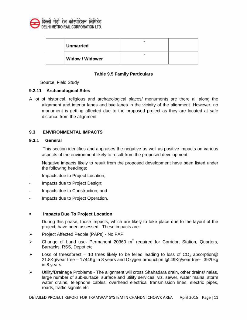
DETAILED PROJECT REPORT FOR TRAMWAY SYSTEM IN CHANDNI CHOWK AREA April 2015 Page |11
Table 9.5 Family Particulars
Source: Field Study
9.2.11 Archaeological Sites
A lot of historical, religious and archaeological places/ monuments are there all along the alignment and interior lanes and bye lanes in the vicinity of the alignment. However, no monument is getting affected due to the proposed project as they are located at safe distance from the alignment
9.3 ENVIRONMENTAL IMPACTS
9.3.1 General
This section identifies and appraises the negative as well as positive impacts on various aspects of the environment likely to result from the proposed development.
Negative impacts likely to result from the proposed development have been listed under the following headings:
- Impacts due to Project Location;
- Impacts due to Project Design;
- Impacts due to Construction; and
- Impacts due to Project Operation.
Impacts Due To Project Location
During this phase, those impacts, which are likely to take place due to the layout of the project, have been assessed. These impacts are:
Project Affected People (PAPs) - No PAP
Change of Land use- Permanent 20360 m2 required for Corridor, Station, Quarters, Barracks, RSS, Depot etc
Loss of trees/forest – 10 trees likely to be felled leading to loss of CO2 absorption@ 21.8Kg/year tree – 1744Kg in 8 years and Oxygen production @ 49Kg/year tree- 3920kg in 8 years.
Utility/Drainage Problems - The alignment will cross Shahadara drain, other drains/ nalas, large number of sub-surface, surface and utility services, viz. sewer, water mains, storm water drains, telephone cables, overhead electrical transmission lines, electric pipes, roads, traffic signals etc.
Unmarried -
Widow / Widower -
DETAILED PROJECT REPORT FOR TRAMWAY SYSTEM IN CHANDNI CHOWK AREA April 2015 Page |12
Socio-economic impacts- No acquisition so no PAP family. However many people will not be able to work in the area after implementation of the project like rickshaw pullers. They would have to be diverted to other parts of walled city like lanes- bye lanes, Chawri Bazar and all other areas except main Chandni Chowk. Rickshaw pullers are not confined to a particular route or area. They can operate wherever they get the passenger. Similarly, the hand cart pullers, Bullock cart operators, goods autos and Heavy labour are having some anxiety about the project but are not scared about their job security as they are very well aware that they are indispensable for market operation and the clients hiring them would search for them for fulfilling their requirements.
Impact on Historical and Cultural Monuments- None
Impacts Due To Project Design
Platform inlets and outlets: No hazard is anticipated due to the proposed sizes of inlets, outlets and platform utilities.
Lighting: Maximum illumination level proposed is 200Lux which provides normal lighting.
Risk Due to Earthquake: The project area lies in Zone IV of Bureau of Indian Standards (BIS) Seismic Zoning Map.
Impacts Due To Project Construction
The most likely negative impacts related to the construction works are: -
During construction period, complete/partial traffic diversions on road will be required. There is safe distance between buildings and proposed corridor.
The Tram route is at Grade and elevated and thus the excavation would be limited to piers and their piling. Some Bentonite muck would also be generated in the project.
The water demand will increase during construction phase for meeting out drinking and domestic water requirement of workers. Water requirement for construction of Tram stations will also be there.
C&D waste such as concrete, stones and dirt generated during construction.
Batching Plant and Casting Yard should be located in an area designated and allotted by MCD/ DDA away from habitation. Consent to establish and operate and authorization for hazardous waste is required from DPCC.
The major sources of noise pollution during construction are movement of vehicles for transportation of construction material to the construction site and the noise generating activity at the construction site itself
Impacts Due To Project Operation
Along with many positive impacts, the project may cause the following negative impacts during operation of the project due to the increase in the number of passengers and trains at the stations:
Noise radiated from train operations and track structures generally constitute the major noise sources. Airborne noise is radiated from at-grade and elevated structures.
The refuse from station includes Garbage, Rubbish, and Floor Sweepings. The solid waste generation is likely to be about 0.8 – 1.2 cum/day at station.
DETAILED PROJECT REPORT FOR TRAMWAY SYSTEM IN CHANDNI CHOWK AREA April 2015 Page |13
The introduction of Tramway implies a change in aesthetics of the streets through which it will operate. An architecturally well designed elevated section can be pleasing to the eyes of beholders.
Impacts Due to Depot:
Water Supply
The water requirement for drinking will be 500 litre per day and 50,000 litre per day for other requirements in Depot. The water after conventional treatment can be processed through Reverse Osmosis (RO) technology for specific use such as final washing of equipment/ trains.
Oil Pollution
The spilled oil should be trapped in oil and grease trap. The collected oil would be disposed off to authorised collectors, so as to avoid any underground/ surface water contamination.
Noise Pollution
The main source of noise from depot is the operation of workshop. Due to less activity, no impact on the ambient noise is anticipated.
Solid Waste
At per available data, it is estimated that about 1 Ton per month of solid waste will be generated from the Depot sites which will be taken by the cleaning contractor weekly and disposed to the Municipal waste disposal sites. Sludge of the order of 250 kg/year is expected to be generated from ETP/STP that will be stored in leak proof containers and disposed off as per DPCC site. Oil and grease of the order of 1326 lts/year will be produced from Depot which will be disposed off through approved re-cyclers. About 1.25 ton/month of iron turning of the PWL for the wheel profiling will be generated from the Depot.
9.4 MOST BENEFIC ENVIRONMENTAL IMPACTS
Various positive impacts have been listed under the following headings:
Employment Opportunities,
Enhancement of Economy,
Mobility,
Traffic Congestion Reduction,s
Reduced Fuel Consumption,
Reduced Air Pollution,
Reduction in Number of Tempos, and
DETAILED PROJECT REPORT FOR TRAMWAY SYSTEM IN CHANDNI CHOWK AREA April 2015 Page |14
Employment Opportunities
The project is likely to be completed in a period of about 2 years. During this period manpower will be needed to take part in various activities. About 800 persons are likely to work during peak period of activity. In operation phase of the project about 100 persons will be employed for operation and maintenance of the proposed system in shifts. Thus the project would provide substantial direct employment.
Enhancement of Economy
The proposed Tram transport facility will facilitate decongestion of Chandni Chowk area. Presently, the whole route area is severely congested. All the goods vehicles and cars are parked on the main road irregularly. This result in very slow movement of men and vehicles which can be seen moving unsystematically i.e. in haphazard manner. Rickshaws ply unsystematically and irregularly. Systematic movement would enable and attract more people to visit the business centre due to convenience and facilities provided by the tram system in Chandni Chowk area.
Mobility
The tramway would increases the mobility of people at comparatively faster rate the corridor served by it. The proposed corridor will provide more people connectivity due to easy and simple accessibility of business centre of Khari Baoli, Chandni Chowk, Nai Sarak, Different Katras and wholesale markets, Naya Bazaar etc with Railway Station and Bus Stands connected with all parts of the city and satellite towns around NCT Delhi. A daily boarding of about 41545 passengers is predicted.
CHECKLIST OF IMPACTS
The impact evaluation determines whether a project development alternative is in compliance with existing standards and regulations. It uses acceptable procedures and attempts to develop a numeric value for total environmental impact. A transformation of the review of multiple environmental objectives into a single value or a ranking or projects is the final step in impact assessment. There are about hundred methods for carrying out impact assessment, which can be grouped into the following categories:
Ad-hoc method, Checklist, Matrix, Network, Overlays, Environmental Index and Cost Benefit analysis.
Each of the methods is subjective in nature and none of these is applicable in every case. Of the 7 methods listed above, checklist has been used and presented. Checklist is a list of environmental parameters or impact indicators which encourages the environmentalist

DETAILED PROJECT REPORT FOR TRAMWAY SYSTEM IN CHANDNI CHOWK AREA April 2015 Page |15
to consider and identify the potential impacts. A typical checklist identifying anticipated environmental impacts is shown in Table 9.6.
Table 9.6 Checklist Of Impacts
S. No.
Parameter Negative Impact
No Impact
Positive Impact
A. Impacts due to Project Location
i. Displacement of People *
ii. Change of Land use and Ecology *
iii. Loss of Cultural and Religious Structures *
iv. Socio-economic Impacts * *
v. Loss of Trees *
vi. Drainage & Utilities Problems *
B. Impact due to Project Design
i. Platforms - Inlets and Outlets *
ii. Ventilation and Lighting *
iii. Station Refuse *
iv. Risk due to Earthquakes *
C. Impact due to Project Construction
i. Top Soil Erosion, Pollution and Health risk *
ii. Traffic Diversions *
iii. Risk to Existing Buildings *
iv. Problems of Soil Disposal and Seepage Risk *
v. Dust Generation *
vi. Increased Water Demand *
vii. Supply of Construction Material *
viii. Construction and Demolition Waste *
ix. Batching Plant and Casting Yard *
x. Noise *
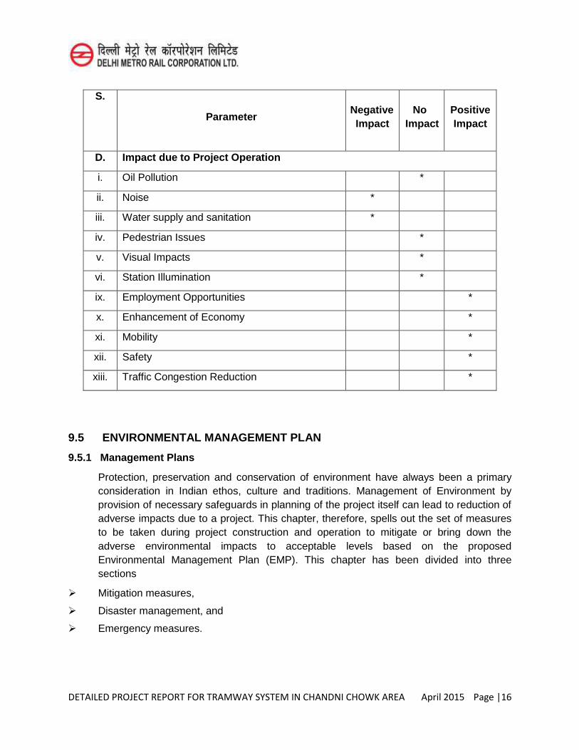
DETAILED PROJECT REPORT FOR TRAMWAY SYSTEM IN CHANDNI CHOWK AREA April 2015 Page |16
S. No.
Parameter Negative Impact
No Impact
Positive Impact
D. Impact due to Project Operation
i. Oil Pollution *
ii. Noise *
iii. Water supply and sanitation *
iv. Pedestrian Issues *
v. Visual Impacts *
vi. Station Illumination *
ix. Employment Opportunities *
x. Enhancement of Economy *
xi. Mobility *
xii. Safety *
xiii. Traffic Congestion Reduction *
9.5 ENVIRONMENTAL MANAGEMENT PLAN
9.5.1 Management Plans
Protection, preservation and conservation of environment have always been a primary consideration in Indian ethos, culture and traditions. Management of Environment by provision of necessary safeguards in planning of the project itself can lead to reduction of adverse impacts due to a project. This chapter, therefore, spells out the set of measures to be taken during project construction and operation to mitigate or bring down the adverse environmental impacts to acceptable levels based on the proposed Environmental Management Plan (EMP). This chapter has been divided into three sections
Mitigation measures,
Disaster management, and
Emergency measures.
DETAILED PROJECT REPORT FOR TRAMWAY SYSTEM IN CHANDNI CHOWK AREA April 2015 Page |17
9.5.2 Mitigation Measures
Mitigation measures have to be adopted during construction at all the construction sites including Batching Plant and Casting Yards on all the aspects.
Compensatory Afforestation: According to the results of the present study, it is found that about 10 trees are likely to be lost due to the project. Compensatory afforestation program will be finalized in consultation with Forest department of GNCTD. Construction Material Management: The scheduling of material procurement and transport shall be linked with construction schedule of the project. Care shall be taken to avoid spillage of material during construction. Labour Camp: All temporary accommodation must be constructed and maintained in such a fashion that uncontaminated water is available for drinking, cooking and washing.
Energy Management: Use of energy efficient motors and pumps; Use of energy efficient lighting, which uses energy efficient luminaries.
Hazardous Waste Management: Outside the storage area, the contractor shall place a ‘display board’, which will display quantity and nature of hazardous waste, on date.
Hazardous Waste needs to be stored in a secure place. It has to be disposed off to authorized agents. Environmental Sanitation: General environmental sanitation shall be carried out by the contractor and ensured at all times at Work Site, Construction Depot, Batching Plant, Labour Camp, Stores, Offices and toilets/urinals. Utility Plan: Utility services shall be kept operational during the entire construction period and after completion of project. Air Pollution Control Measures: The Contractor shall take all necessary precautions to minimize fugitive dust emissions from operations involving excavation, grading, and clearing of land and disposal of waste. The Contractor shall use construction equipment so as to minimize or control of air pollution. Contractor’s transport vehicles and other
equipment shall conform to emission standards fixed by Statutory Agencies. The Contractor shall carry out periodical checks and undertake remedial measures including replacement so as to operate within permissible norms. Construction and Demolition Waste: Opportunities for reducing Construction and demolition waste focus on three approaches, typically expressed as Reduce-Reuse-Recycle. An effort shall be made to recover embedded energy and to recycle the maximum quantity of Construction and demolition waste to manufacture tiles, curb stones, paver block etc. There shall be no disposal of any waste along Yamuna bed, storm water drains, Shahadara drain and/ or any other water body or depression. Rather Construction and
DETAILED PROJECT REPORT FOR TRAMWAY SYSTEM IN CHANDNI CHOWK AREA April 2015 Page |18
demolition waste shall be collected and sent to ILFS Burari Plant which is an authorized waste recycling facility or to dispose in low lying areas with the consent of the owner of land.
Noise Control Measures: During construction the exposure of workers to high noise levels especially near the machinery need to be minimized. This could be achieved by: Job rotation; Automation; Construction of permanent and temporary noise barriers; Use electric instead of diesel powered equipment; Use hydraulic tools instead of pneumatic tools; Acoustic enclosures should be provided for individual noise generating construction equipment like DG sets,
Traffic Diversion/Management: In order to retain satisfactory levels of traffic flow during the construction period; traffic management and engineering measures need to be taken. They can be road widening exercises, traffic segregation, one-way movements, traffic diversions on influence area roads, acquisition of service lanes, etc. Maintenance of diverted roads in good working condition to avoid slow down and congestion shall be a prerequisite during construction period.
Soil Erosion Control: The surface area of erodible earth material exposed by clearing and grubbing, excavation shall be limited to the extent practicable. Immediate control measures would be provided to prevent soil erosion and sedimentation that will adversely affect construction operations, damage adjacent properties, or cause contamination of nearby streams or other watercourses.
Sanitation and Solid Waste management:
During Construction
The public health facilities, such as water supply, sanitation and toilets are much needed at the construction sites and labour camps. Water should be treated before use up to drinking water standards. The sewerage disposal systems should be adopted for sewage disposal. The water for domestic consumption shall be sourced from Delhi Jal Board or alternatively designated bore wells may be installed with due permission from statuatory authority prior to installation of bore well. Solid waste shall be stacked at designated place and when sufficient quantity accumulates it shall be disposed off through covered trucks to land fill site designated and authorized by Municipal Authority.
During Operations
No public facilities is provided at stations. Solid waste will be generated at station to the tune of 0.8 – 1.2 m3/Day. The storage containers for this purpose need to be designed.
Rain water harvesting: To conserve and augment the storage of groundwater, it has been proposed to construct roof top rainwater harvesting structure of suitable capacity in the alignment.
Tree Protection: There is requirement of felling 10 trees. An attempt shall be made to minimize the tree felling. As remediation of tree felling it is suggested to plant ten times the number of trees for each tree felled. Moreover the proposed CCTC would chalk out the plantation program in close coordination with Forest Department by making the payment for plantation work including after care for three years.
Training and Extension: The training for engineers and managers is imparted by DMRC on regular basis to implement the environmental protection clauses of the tender
DETAILED PROJECT REPORT FOR TRAMWAY SYSTEM IN CHANDNI CHOWK AREA April 2015 Page |19
document and to implement the best environmental practices during the construction phase.
DISASTER MANAGEMENT:
Once the likelihood of a disaster is suspected, action has to be initiated to prevent a failure. Engineers responsible for preventive action should identify sources of repair equipments, materials, labour and expertise for use during emergency.
Reporting Procedures: The Engineer-incharge should notify for the following information:
Exit points for the public,
Safety areas in the tunnel/overhead rail, and
Nearest medical facility
Communication System: An efficient communication system is absolutely essential for the success of any disaster management plan. The damage areas need to be clearly identified and provided with temporary and fool proof communication system.
Emergency Action Committee: To ensure coordinates action, an Emergency Action Committee should be constituted. The civic administrator may be the Chairman of this Committee. Emergency Action Committee will prepare the evacuation plan and procedures for implementation based on local needs and facilities available
EMERGENCY MEASURES:
The emergency measures are adopted to avoid any failure in the system such as lights, fire, means of escape etc. The aim of Emergency Action Plan is to identify areas, population and structures likely to be affected due to a catastrophic event of accident. The action plan should also include preventive action, notification, warning procedures and co-ordination among various relief authorities. These are broadly categorized as below.
Emergency Lighting
Fire Protection
Fire prevention measures,
Fire control measures,
Fire detection systems,
Means of escape,
Access for fireman, and
Means of fire fighting
Emergency Door
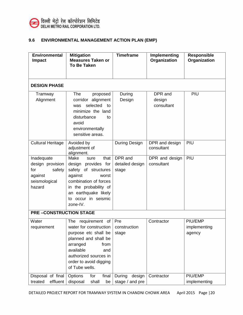
DETAILED PROJECT REPORT FOR TRAMWAY SYSTEM IN CHANDNI CHOWK AREA April 2015 Page |20
9.6 ENVIRONMENTAL MANAGEMENT ACTION PLAN (EMP)
Environmental Impact
Mitigation Measures Taken or To Be Taken
Timeframe Implementing Organization
Responsible Organization
DESIGN PHASE
Tramway Alignment
The proposed corridor alignment was selected to minimize the land disturbance to avoid environmentally sensitive areas.
During Design
DPR and design consultant
PIU
Cultural Heritage Avoided by adjustment of alignment.
During Design DPR and design consultant
PIU
Inadequate design provision for safety against seismological hazard
Make sure that design provides for safety of structures against worst combination of forces in the probability of an earthquake likely to occur in seismic zone-IV.
DPR and detailed design stage
DPR and design consultant
PIU
PRE –CONSTRUCTION STAGE
Water requirement
The requirement of water for construction purpose etc shall be planned and shall be arranged from available and authorized sources in order to avoid digging of Tube wells.
Pre construction stage
Contractor PIU/EMP implementing agency
Disposal of final treated effluent
Options for final disposal shall be
During design stage / and pre
Contractor PIU/EMP implementing
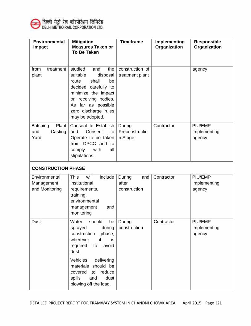
DETAILED PROJECT REPORT FOR TRAMWAY SYSTEM IN CHANDNI CHOWK AREA April 2015 Page |21
Environmental Impact
Mitigation Measures Taken or To Be Taken
Timeframe Implementing Organization
Responsible Organization
from treatment plant
studied and the suitable disposal route shall be decided carefully to minimize the impact on receiving bodies. As far as possible zero discharge rules may be adopted.
construction of treatment plant
agency
Batching Plant and Casting Yard
Consent to Establish and Consent to Operate to be taken from DPCC and to comply with all stipulations.
During Preconstruction Stage
Contractor PIU/EMP implementing agency
CONSTRUCTION PHASE
Environmental Management and Monitoring
This will include institutional requirements, training, environmental management and monitoring
During and after construction
Contractor PIU/EMP implementing agency
Dust Water should be sprayed during construction phase, wherever it is required to avoid dust.
Vehicles delivering materials should be covered to reduce spills and dust blowing off the load.
During construction
Contractor PIU/EMP implementing agency
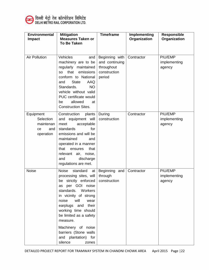
DETAILED PROJECT REPORT FOR TRAMWAY SYSTEM IN CHANDNI CHOWK AREA April 2015 Page |22
Environmental Impact
Mitigation Measures Taken or To Be Taken
Timeframe Implementing Organization
Responsible Organization
Air Pollution Vehicles and machinery are to be regularly maintained so that emissions conform to National and State AAQ Standards. NO vehicle without valid PUC certificate would be allowed at Construction Sites.
Beginning with and continuing throughout construction period
Contractor PIU/EMP implementing agency
Equipment Selection maintenance and operation
Construction plants and equipment will meet acceptable standards for emissions and will be maintained and operated in a manner that ensures that relevant air, noise, and discharge regulations are met.
During construction
Contractor PIU/EMP implementing agency
Noise Noise standard at processing sites, will be strictly enforced as per GOI noise standards. Workers in vicinity of strong noise will wear earplugs and their working time should be limited as a safety measure.
Machinery of noise barriers (Stone walls and plantation) for silence zones
Beginning and through construction
Contractor PIU/EMP implementing agency
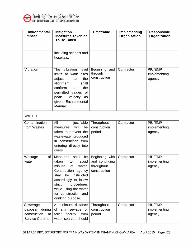
DETAILED PROJECT REPORT FOR TRAMWAY SYSTEM IN CHANDNI CHOWK AREA April 2015 Page |23
Environmental Impact
Mitigation Measures Taken or To Be Taken
Timeframe Implementing Organization
Responsible Organization
including schools and hospitals.
Vibration The vibration level limits at work sites adjacent to the alignment shall conform to the permitted values of peak velocity as given Environmental Manual
Beginning and through construction
Contractor PIU/EMP implementing agency
WATER
Contamination from Wastes
All justifiable measures will be taken to prevent the wastewater produced in construction from entering directly into rivers
Throughout construction period
Contractor PIU/EMP implementing agency
Wastage of water
Measures shall be taken to avoid misuse of water. Construction agency shall be instructed accordingly to follow strict procedures while using the water for construction and drinking purpose.
Beginning with and continuing throughout construction
Contractor PIU/EMP implementing agency
Sewerage disposal during construction at Service Centres
A minimum distance of any sewage or toilet facility from water sources should
Throughout construction period
Contractor PIU/EMP implementing agency
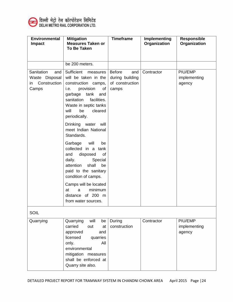
DETAILED PROJECT REPORT FOR TRAMWAY SYSTEM IN CHANDNI CHOWK AREA April 2015 Page |24
Environmental Impact
Mitigation Measures Taken or To Be Taken
Timeframe Implementing Organization
Responsible Organization
be 200 meters.
Sanitation and Waste Disposal in Construction Camps
Sufficient measures will be taken in the construction camps, i.e. provision of garbage tank and sanitation facilities. Waste in septic tanks will be cleared periodically.
Drinking water will meet Indian National Standards.
Garbage will be collected in a tank and disposed of daily. Special attention shall be paid to the sanitary condition of camps.
Camps will be located at a minimum distance of 200 m from water sources.
Before and during building of construction camps
Contractor PIU/EMP implementing agency
SOIL
Quarrying Quarrying will be carried out at approved and licensed quarries only. All environmental mitigation measures shall be enforced at Quarry site also.
During construction
Contractor PIU/EMP implementing agency
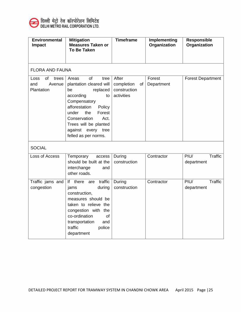
DETAILED PROJECT REPORT FOR TRAMWAY SYSTEM IN CHANDNI CHOWK AREA April 2015 Page |25
Environmental Impact
Mitigation Measures Taken or To Be Taken
Timeframe Implementing Organization
Responsible Organization
FLORA AND FAUNA
Loss of trees and Avenue Plantation
Areas of tree plantation cleared will be replaced according to Compensatory afforestation Policy under the Forest Conservation Act. Trees will be planted against every tree felled as per norms.
After completion of construction activities
Forest Department
Forest Department
SOCIAL
Loss of Access Temporary access should be built at the interchange and other roads.
During construction
Contractor PIU/ Traffic department
Traffic jams and congestion
If there are traffic jams during construction, measures should be taken to relieve the congestion with the co-ordination of transportation and traffic police department
During construction
Contractor PIU/ Traffic department
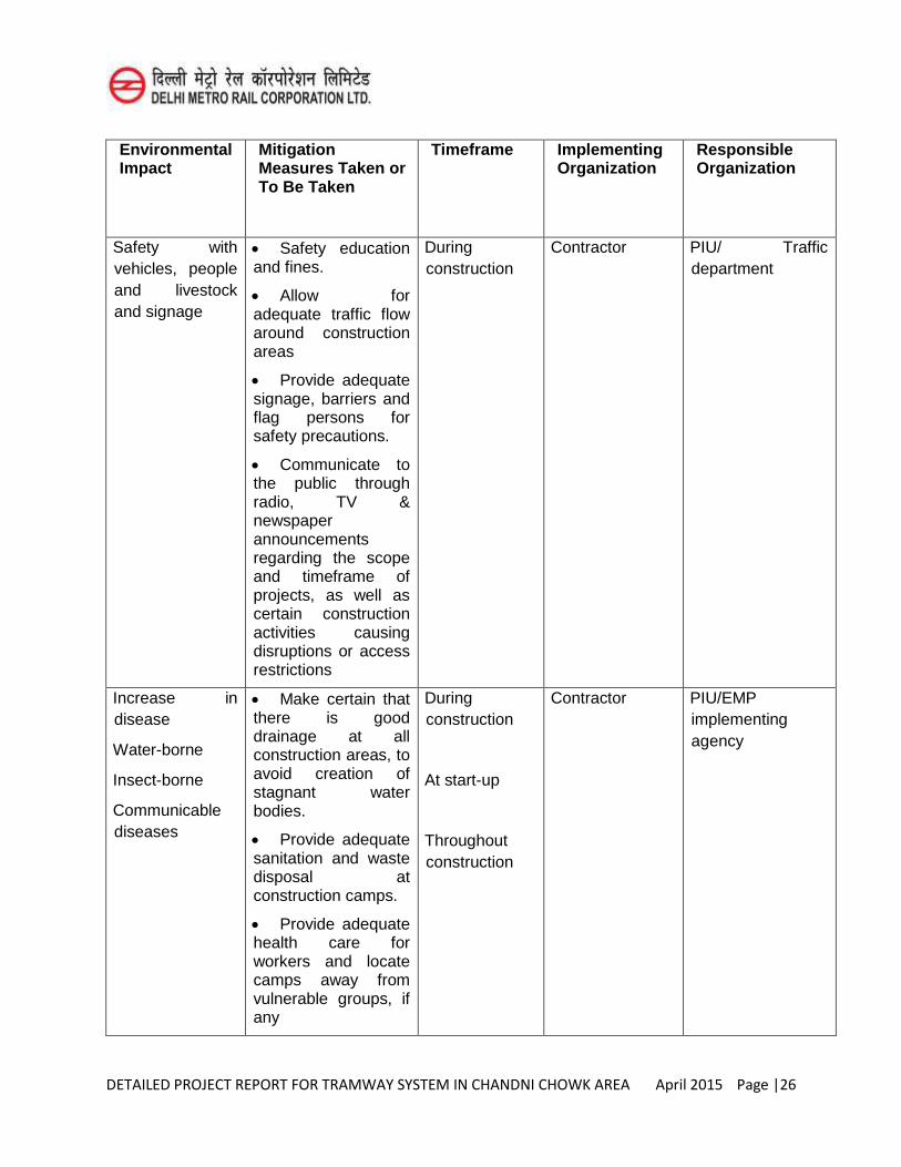
DETAILED PROJECT REPORT FOR TRAMWAY SYSTEM IN CHANDNI CHOWK AREA April 2015 Page |26
Environmental Impact
Mitigation Measures Taken or To Be Taken
Timeframe Implementing Organization
Responsible Organization
Safety with vehicles, people and livestock and signage
Safety education and fines.
Allow for adequate traffic flow around construction areas
Provide adequate signage, barriers and flag persons for safety precautions.
Communicate to the public through radio, TV & newspaper announcements regarding the scope and timeframe of projects, as well as certain construction activities causing disruptions or access restrictions
During construction
Contractor PIU/ Traffic department
Increase in disease
Water-borne
Insect-borne
Communicable diseases
Make certain that there is good drainage at all construction areas, to avoid creation of stagnant water bodies.
Provide adequate sanitation and waste disposal at construction camps.
Provide adequate health care for workers and locate camps away from vulnerable groups, if any
During construction
At start-up
Throughout construction
Contractor PIU/EMP implementing agency
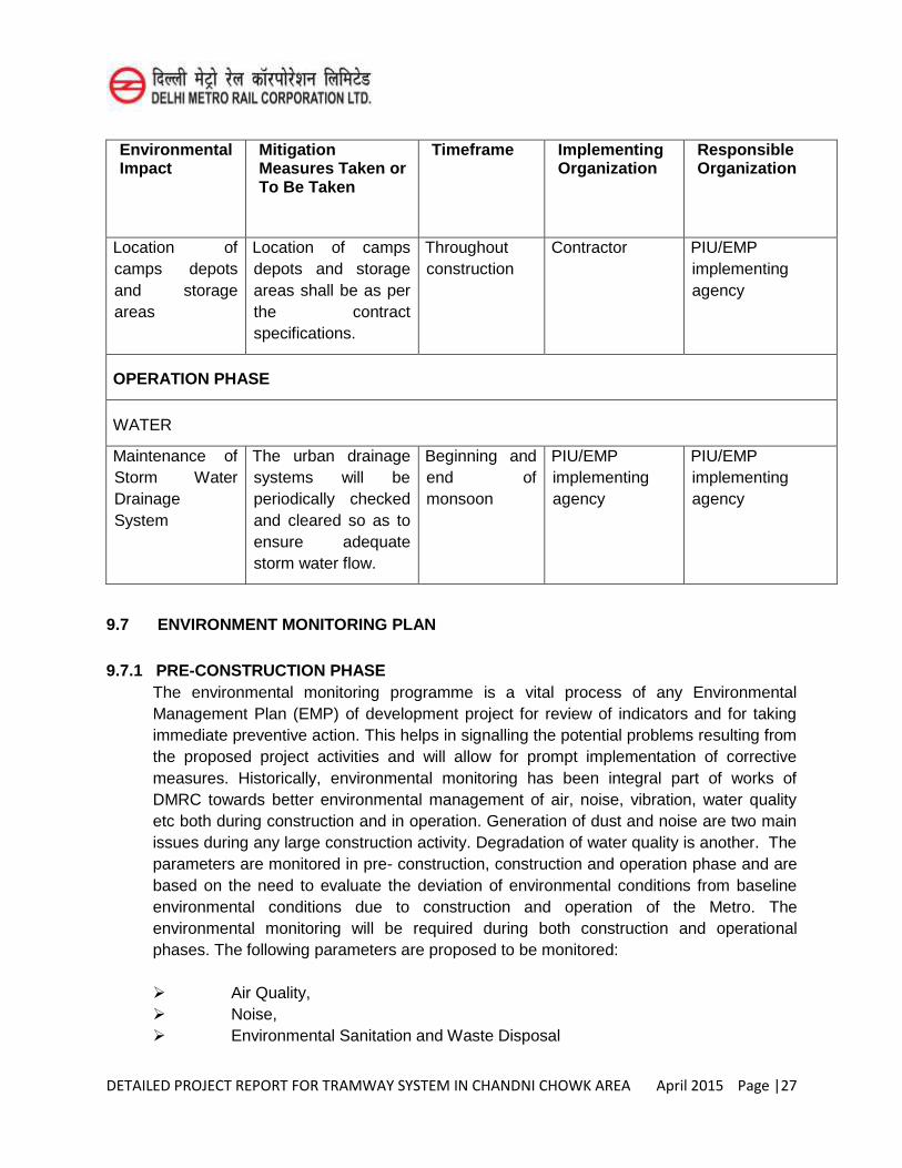
DETAILED PROJECT REPORT FOR TRAMWAY SYSTEM IN CHANDNI CHOWK AREA April 2015 Page |27
Environmental Impact
Mitigation Measures Taken or To Be Taken
Timeframe Implementing Organization
Responsible Organization
Location of camps depots and storage areas
Location of camps depots and storage areas shall be as per the contract specifications.
Throughout construction
Contractor PIU/EMP implementing agency
OPERATION PHASE
WATER
Maintenance of Storm Water Drainage System
The urban drainage systems will be periodically checked and cleared so as to ensure adequate storm water flow.
Beginning and end of monsoon
PIU/EMP implementing agency
PIU/EMP implementing agency
9.7 ENVIRONMENT MONITORING PLAN
9.7.1 PRE-CONSTRUCTION PHASE The environmental monitoring programme is a vital process of any Environmental
Management Plan (EMP) of development project for review of indicators and for taking immediate preventive action. This helps in signalling the potential problems resulting from the proposed project activities and will allow for prompt implementation of corrective measures. Historically, environmental monitoring has been integral part of works of DMRC towards better environmental management of air, noise, vibration, water quality etc both during construction and in operation. Generation of dust and noise are two main issues during any large construction activity. Degradation of water quality is another. The parameters are monitored in pre- construction, construction and operation phase and are based on the need to evaluate the deviation of environmental conditions from baseline environmental conditions due to construction and operation of the Metro. The environmental monitoring will be required during both construction and operational phases. The following parameters are proposed to be monitored:
Air Quality, Noise, Environmental Sanitation and Waste Disposal
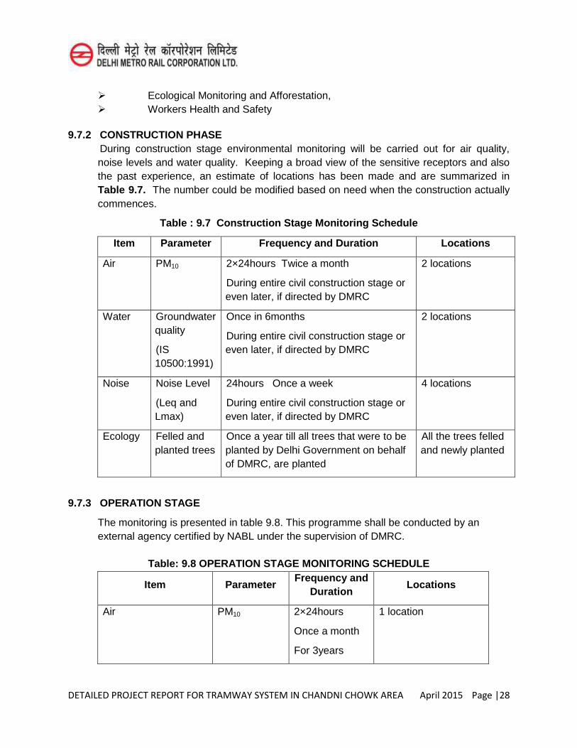
DETAILED PROJECT REPORT FOR TRAMWAY SYSTEM IN CHANDNI CHOWK AREA April 2015 Page |28
Ecological Monitoring and Afforestation, Workers Health and Safety
9.7.2 CONSTRUCTION PHASE During construction stage environmental monitoring will be carried out for air quality,
noise levels and water quality. Keeping a broad view of the sensitive receptors and also the past experience, an estimate of locations has been made and are summarized in Table 9.7. The number could be modified based on need when the construction actually commences.
Table : 9.7 Construction Stage Monitoring Schedule
Item Parameter Frequency and Duration Locations
Air PM10 2×24hours Twice a month
During entire civil construction stage or even later, if directed by DMRC
2 locations
Water Groundwater quality
(IS 10500:1991)
Once in 6months
During entire civil construction stage or even later, if directed by DMRC
2 locations
Noise Noise Level
(Leq and Lmax)
24hours Once a week
During entire civil construction stage or even later, if directed by DMRC
4 locations
Ecology Felled and planted trees
Once a year till all trees that were to be planted by Delhi Government on behalf of DMRC, are planted
All the trees felled and newly planted
9.7.3 OPERATION STAGE
The monitoring is presented in table 9.8. This programme shall be conducted by an external agency certified by NABL under the supervision of DMRC.
Table: 9.8 OPERATION STAGE MONITORING SCHEDULE
Item Parameter Frequency and
Duration Locations
Air PM10 2×24hours
Once a month
For 3years
1 location
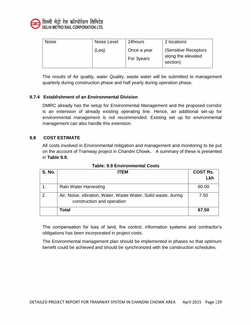
DETAILED PROJECT REPORT FOR TRAMWAY SYSTEM IN CHANDNI CHOWK AREA April 2015 Page |29
Noise Noise Level
(Leq)
24hours
Once a year
For 3years
2 locations
(Sensitive Receptors along the elevated section)
The results of Air quality, water Quality, waste water will be submitted to management quarterly during construction phase and half yearly during operation phase.
9.7.4 Establishment of an Environmental Division
DMRC already has the setup for Environmental Management and the proposed corridor is an extension of already existing operating line. Hence, an additional set-up for environmental management is not recommended. Existing set up for environmental management can also handle this extension.
9.8 COST ESTIMATE
All costs involved in Environmental mitigation and management and monitoring to be put on the account of Tramway project in Chandni Chowk. A summary of these is presented in Table 9.9.
Table: 9.9 Environmental Costs S. No. ITEM COST Rs.
Lkh
1. Rain Water Harvesting 60.00
2. Air, Noise, vibration, Water, Waste Water, Solid waste, during construction and operation
7.50
Total 67.50
The compensation for loss of land, fire control, information systems and contractor’s
obligations has been incorporated in project costs.
The Environmental management plan should be implemented in phases so that optimum benefit could be achieved and should be synchronized with the construction schedules.
DETAILED PROJECT REPORT FOR TRAMWAY SYSTEM IN CHANDNI CHOWK AREA April 2015 Page |30
9.9 CONCLUSION
The environmental impacts stemming out of the proposed project can be mitigated with simple set of measures, dealing with careful planning and designing of the Tram alignment and structures. Adequate provision of environmental clauses in work contracts and efficient contract management will eliminate or reduce significantly all possible problems. A common problem encountered during implementation of environmental management plans of such projects is lack of environmental awareness among engineers and managers concerned with day to day construction activities, which can be solved through regular environmental training programs.
DETAILED PROJECT REPORT FOR TRAMWAY SYSTEM IN CHANDNI CHOWK AREA April 2015 Page |1
CHAPTER-10
COST ESTIMATE
10.1 INTRODUCTION
Detailed cost estimate for Tramway system in Chandni Chowk area has been prepared covering
civil, Electrical, Signalling and Telecommunication works, Rolling stock, and Environment
protection, Substations and Depot for stabling, washing and maintenance etc. Considering
overhead traction system in elevated track and APS system at grade at the price level of March
2015 provided by the consultants based on their experience in other projects in Spain, Northern
Africa and South America.
While preparing the capital cost estimates various items have generally been grouped under
three major heads on the basis of (i) route kilometre length of the alignment (ii)Number of units
of that item, and (iii) item being an independent entry. All items related with alignment, whether
elevated or at-grade, traction, Signalling & telecommunication, whether in main lines or in
maintenance depot, have been estimated at rate per route Km basis. Cost of station/stoppage
structures, other electrical services at these station/stoppage including lifts& escalators and
automatic fare collection(AFC) installations at all stations/stoppages have been assessed in
terms of each station/stoppage as a unit. Similarly Rolling stock cost has been estimated in
terms of number of units required. In remaining items, viz. land cost on circle rates of land in
Chandni Chowk area, utility diversions, environment protection etc. the costs have been
assessed on the basis of each item, taken as an independent entity.
7% general charges on the total cost of all items except land cost have been added. Another
3% Continegencies charges have been added to the cost after adding 7% General Charges.
The detail of taxes and duties has been worked out separately.
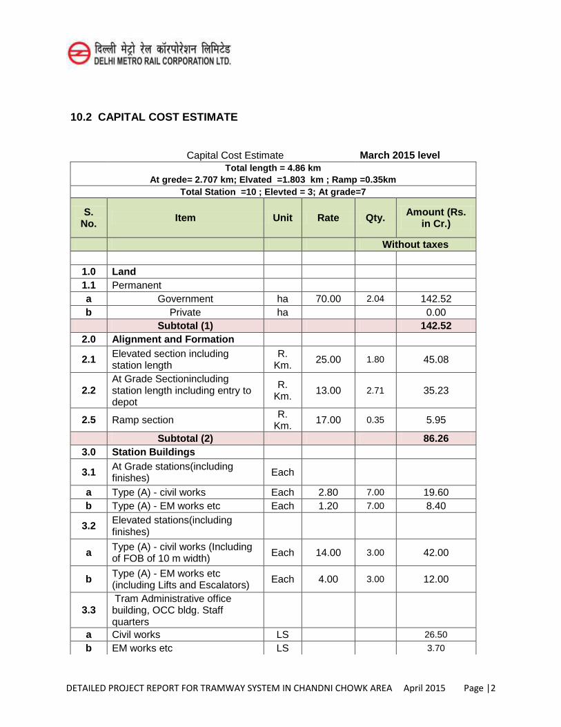
DETAILED PROJECT REPORT FOR TRAMWAY SYSTEM IN CHANDNI CHOWK AREA April 2015 Page |2
10.2 CAPITAL COST ESTIMATE
Capital Cost Estimate March 2015 level Total length = 4.86 km
At grede= 2.707 km; Elvated =1.803 km ; Ramp =0.35km Total Station =10 ; Elevted = 3; At grade=7
S. No. Item Unit Rate Qty. Amount (Rs.
in Cr.)
Without taxes
1.0 Land 1.1 Permanent a Government ha 70.00 2.04 142.52 b Private ha 0.00 Subtotal (1) 142.52
2.0 Alignment and Formation
2.1 Elevated section including station length
R. Km. 25.00 1.80 45.08
2.2 At Grade Sectionincluding station length including entry to depot
R. Km. 13.00 2.71 35.23
2.5 Ramp section R. Km. 17.00 0.35 5.95
Subtotal (2) 86.26 3.0 Station Buildings
3.1 At Grade stations(including finishes) Each
a Type (A) - civil works Each 2.80 7.00 19.60 b Type (A) - EM works etc Each 1.20 7.00 8.40
3.2 Elevated stations(including finishes)
a Type (A) - civil works (Including of FOB of 10 m width) Each 14.00 3.00 42.00
b Type (A) - EM works etc (including Lifts and Escalators) Each 4.00 3.00 12.00
3.3 Tram Administrative office building, OCC bldg. Staff quarters
a Civil works LS 26.50
b EM works etc LS 3.70
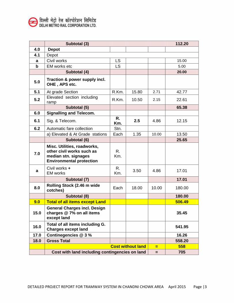
DETAILED PROJECT REPORT FOR TRAMWAY SYSTEM IN CHANDNI CHOWK AREA April 2015 Page |3
Subtotal (3) 112.20 4.0 Depot 4.1 Depot a Civil works LS 15.00
b EM works etc LS 5.00
Subtotal (4) 20.00
5.0 Traction & power supply incl. OHE , APS etc.
5.1 At grade Section R.Km. 15.80 2.71 42.77
5.2 Elevated section including ramp R.Km. 10.50 2.15 22.61
Subtotal (5) 65.38 6.0 Signalling and Telecom.
6.1 Sig. & Telecom. R. Km. 2.5 4.86 12.15
6.2 Automatic fare collection Stn. a) Elevated & At Grade stations Each 1.35 10.00 13.50 Subtotal (6) 25.65
7.0
Misc. Utilities, roadworks, other civil works such as median stn. signages Environmental protection
R. Km.
a Civil works + EM works
R. Km. 3.50 4.86 17.01
Subtotal (7) 17.01
8.0 Rolling Stock (2.46 m wide cotches) Each 18.00 10.00 180.00
Subtotal (8) 180.00 9.0 Total of all items except Land 506.49
15.0 General Charges incl. Design charges @ 7% on all items except land
35.45
16.0 Total of all items including G. Charges except land 541.95
17.0 Continegencies @ 3 % 16.26 18.0 Gross Total 558.20
Cost without land = 558 Cost with land including contingencies on land = 705
DETAILED PROJECT REPORT FOR TRAMWAY SYSTEM IN CHANDNI CHOWK AREA April 2015 Page |4
10.3 CIVIL ENGINEERING WORKS
10.3.1 Land
(i) Land requirements have been kept to the barest minimum & worked out on area basis. For elevated and at grade, no land is proposed to be acquired. However the land for construction of depot and substations is required to be transferred from DDA & civic authorities.
(ii) Total land for depot and substation is 20,360 sqm .i.e. 20.036 ha.
(iii)The circle rates for Chandni Chowk area of Delhi Govt taken from website www.mapsofindia.com/delhi/information/mcd-circle-rates.html
10.3.2 Formation, Alignment
(i)Total length is 4.86km, at grade length is 2.707 km(2.347km + 0.36 km for depot ) , Elevated length is 1.803 km and Elevated ramp is 0.35 km.
(ii) Rates per km for track at grade and for elevated track are based on priced level of March 2015 provided by the consultant based on their experience in other projects in Spain, Northern Africa and South America.
10.3.3 PERMANENT WAY
Ballastless track and rail embedded in concrete have been taken in the estimate for at grade and for elevated track. Track to depot has been planned at grade
10.4 DEPOT
Separate tram maintainance depot cum workshop has been proposed on at Tee junction of patel road and Netaji Subhash marg. Which will have a Administrative Building, Workshop building, stabling tracks, Boundary wall, plants and machinery etc.
10.5 UTILITY DIVERSION
The cost of utility diversions involved in the stretch have been considered separately and provided for in the estimate. In addition to sewer/drainage/water pipelines other important utilities works considered are road diversions, road restoration etc. Cost provision has been made on route km basis based on experience of Delhi Metro.
10.6 ENVIRONMENT IMPACT ASSESSMENT
Provision for environment impacts of the proposed tramway system in Chandni Chowk area has been made to cover various protection works, additional compensatory measures, compensation for loss of trees, compensation afforestation and fencing,
DETAILED PROJECT REPORT FOR TRAMWAY SYSTEM IN CHANDNI CHOWK AREA April 2015 Page |5
monitoring of water quality, air/noise pollution during construction, establishment of Environment Diversion.
10.7 TRACTION AND POWER SUPPLY
Provisions have been made to cover following subheads:
OHE for elevated and APS at grade Receiving-cum-Traction Sub-stations including cables Service connection charges for receiving Sub-station. Scada augmentation. Miscellaneous items e.g. illumination, lifting T&P etc
10.8 ELECTRICAL SERVICES AT STOPPAGES
These are included in estimated cost of tramway stoppages .Cost of escalators and lifts for elevated stations/stoppages have been included in the station/stoppage cost.
10.9 SIGNALLING & TELECOMMUNICATION WORKS
The adopted rates provided by the consultants have been reduced from 4.2Cr/km to 2.5Cr/km based on assessment by DMRC for similar work in March 2015 price level.
10.10 AUTOMATIC FARE COLLECTION
Automatic Fare collection provision on all stoppages have been taken for the adopted rates provided by the consultants based on their experience in other projects in Spain, Northern Africa and South America.
10.11 ROLLING STOCK
10 numbers of 20.13m long tramway provision have been taken .The rates adopted for cost estimate have been provided by the consultant based on their experience in other projects in Spain, Northern Africa and South America.
10.12 FOOT OVER BRIDGE
Cost of 10m width Foot over bridge have been added to the cost of stations in the elevated corridor.
10.13 TAXES AND DUTIES
The component of Import Duty, Excise Duty and VAT is not included in the Capital cost estimated. The estimated taxes and duties work out to Rs. 107 Cr
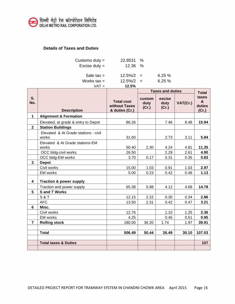
DETAILED PROJECT REPORT FOR TRAMWAY SYSTEM IN CHANDNI CHOWK AREA April 2015 Page |6
Details of Taxes and Duties
Customs duty = 22.8531 %
Excise duty = 12.36 %
Sale tax =
12.5%/2
= 6.25 %
Works tax = 12.5%/2 = 6.25 %
VAT = 12.5%
S. No.
Description
Total cost without Taxes & duties (Cr.)
Taxes and duties Total taxes
& duties (Cr.)
custom duty (Cr.)
excise duty (Cr.)
VAT(Cr.)
1 Alignment & Formation
Elevated, at grade & entry to Depot 86.26 7.46 8.48 15.94 2 Station Buildings
Elevated & At Grade stations - civil works 31.60 2.73 3.11 5.84
Elevated & At Grade stations-EM works 50.40 2.30 4.24 4.81 11.35
OCC bldg-civil works 26.50 2.29 2.61 4.90 OCC bldg-EM works 3.70 0.17 0.31 0.35 0.83 3 Depot
Civil works 15.00 1.03 0.91 1.03 2.97 EM works 5.00 0.23 0.42 0.48 1.13
4 Traction & power supply Traction and power supply 65.38 5.98 4.12 4.68 14.78 5 S and T Works S & T 12.15 2.22 0.30 0.34 2.86 AFC 13.50 2.31 0.42 0.47 3.21 6 Misc. Civil works 12.76 1.10 1.25 2.36 EM works 4.25 0.45 0.51 0.95 7 Rolling stock 180.00 36.20 1.74 1.97 39.91 Total 506.49 50.44 26.49 30.10 107.03 Total taxes & Duties 107
DETAILED PROJECT REPORT FOR TRAMWAY SYSTEM IN CHANDNI CHOWK AREA April 2015 Page |1
CHAPTER 11
FINANCING OPTIONS, FARE STRUCTURE AND FINANCIAL VIABILITY
11.1 INTRODUCTION
Tramway system at Chandni Chowk area of Delhi is proposed to be constructed with an estimated cost of Rs 782.00 Crore with central taxes and land cost but excluding state taxes. The route length of the said Tramway system and estimated cost at March-2015 price level including land cost excluding central taxes and including land & central taxes is placed in table 11.1 as under:
Table 11.1 Cost Details
Distance (KMs)
Estimated cost including land cost & excluding central taxes
(Rs/Crore)
Estimated cost including land & Central taxes (Rs/Crore)
4.86 705.00 782.00 One time capital expenditure and recurring expenditure (salary and allowances of security personal) has not been taken in the FIRR calculation since the security of the Tramway system rests with the central government.
11.2 Costs
11.2.1 Investment Cost
11.2.1.1 The taxes and duties consist of Custom Duty (CD), Excise Duty (ED) and State Value Added Tax (VAT). It is assumed that the Central Government will include the Tramway project under chapter 98.01 of the Custom Tariff Act for availing concessional project import duty. The effective CD works out to 22.85% (Basic CD (5%), Countervail Duty (CVD)+ Additional Custom Duty (ACD)) on the imported portions and ED @ 12.50% and VAT @ 12.50% on indigenously manufactured items, which have been considered for working out the estimated taxes and duties. For the purpose of working the Financial Internal Rate of Return (FIRR), the estimated cost at March-2015 price level along with the cost of land, central taxes & state taxes has been taken with an escalation factor @ 7.50% per annum on all items to arrive at the completion cost. It is assumed that Government of NCT of Delhi will provide interest free Subordinate Debt towards DVAT which will be paid back by the SPV after the senior debts have been fully paid back. Service Tax on “Works Contract Services” on new construction pertaining to railways, including Monorail or Metro Rail Projects is exempted from the Service Tax and therefore the same has been considered as Nil in the estimated cost.
11.2.1.2 It is assumed that the construction work will start on 01.10.2015 and is expected to
be completed on 31.03.2018. The Revenue Opening Date (ROD) has been
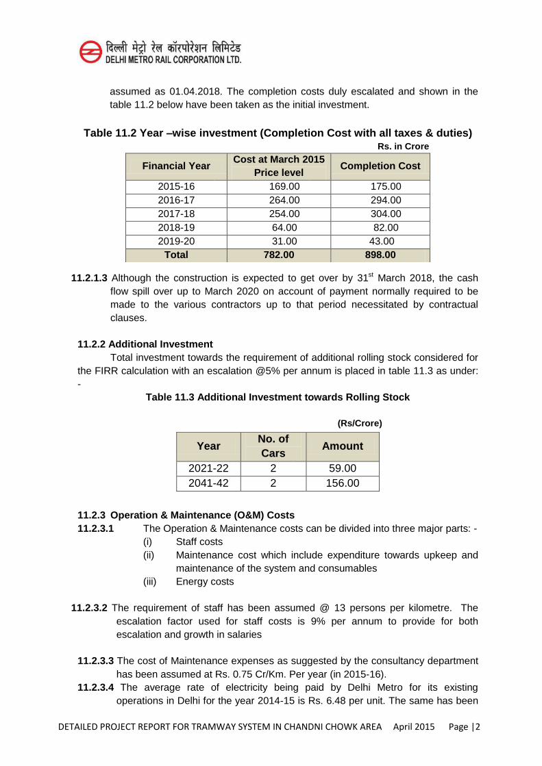
DETAILED PROJECT REPORT FOR TRAMWAY SYSTEM IN CHANDNI CHOWK AREA April 2015 Page |2
assumed as 01.04.2018. The completion costs duly escalated and shown in the table 11.2 below have been taken as the initial investment.
Table 11.2 Year –wise investment (Completion Cost with all taxes & duties)
Rs. in Crore
11.2.1.3 Although the construction is expected to get over by 31st March 2018, the cash flow spill over up to March 2020 on account of payment normally required to be made to the various contractors up to that period necessitated by contractual clauses.
11.2.2 Additional Investment
Total investment towards the requirement of additional rolling stock considered for the FIRR calculation with an escalation @5% per annum is placed in table 11.3 as under: -
Table 11.3 Additional Investment towards Rolling Stock
(Rs/Crore)
11.2.3 Operation & Maintenance (O&M) Costs 11.2.3.1 The Operation & Maintenance costs can be divided into three major parts: -
(i) Staff costs (ii) Maintenance cost which include expenditure towards upkeep and
maintenance of the system and consumables (iii) Energy costs
11.2.3.2 The requirement of staff has been assumed @ 13 persons per kilometre. The
escalation factor used for staff costs is 9% per annum to provide for both escalation and growth in salaries
11.2.3.3 The cost of Maintenance expenses as suggested by the consultancy department
has been assumed at Rs. 0.75 Cr/Km. Per year (in 2015-16). 11.2.3.4 The average rate of electricity being paid by Delhi Metro for its existing
operations in Delhi for the year 2014-15 is Rs. 6.48 per unit. The same has been
Financial Year Cost at March 2015
Price level Completion Cost
2015-16 169.00 175.00 2016-17 264.00 294.00 2017-18 254.00 304.00 2018-19 64.00 82.00 2019-20 31.00 43.00
Total 782.00 898.00
Year No. of Cars
Amount
2021-22 2 59.00 2041-42 2 156.00
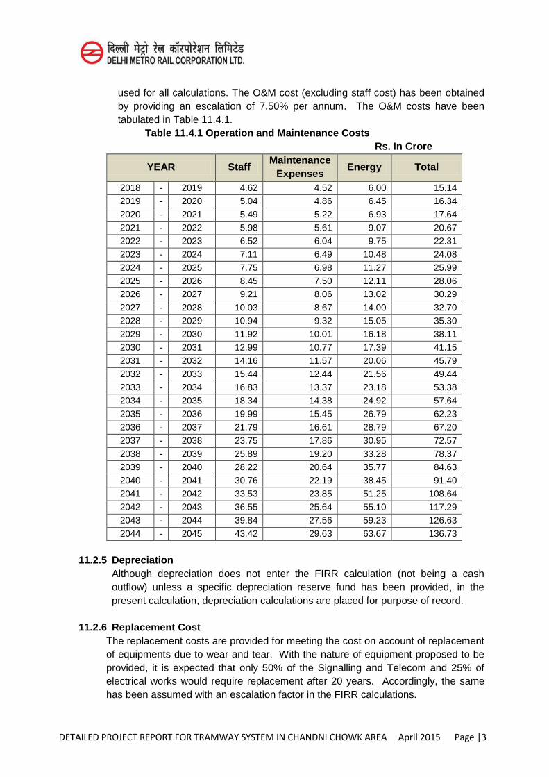
DETAILED PROJECT REPORT FOR TRAMWAY SYSTEM IN CHANDNI CHOWK AREA April 2015 Page |3
used for all calculations. The O&M cost (excluding staff cost) has been obtained by providing an escalation of 7.50% per annum. The O&M costs have been tabulated in Table 11.4.1.
Table 11.4.1 Operation and Maintenance Costs Rs. In Crore
YEAR Staff Maintenance
Expenses Energy Total
2018 - 2019 4.62 4.52 6.00 15.14
2019 - 2020 5.04 4.86 6.45 16.34
2020 - 2021 5.49 5.22 6.93 17.64
2021 - 2022 5.98 5.61 9.07 20.67
2022 - 2023 6.52 6.04 9.75 22.31
2023 - 2024 7.11 6.49 10.48 24.08
2024 - 2025 7.75 6.98 11.27 25.99
2025 - 2026 8.45 7.50 12.11 28.06
2026 - 2027 9.21 8.06 13.02 30.29
2027 - 2028 10.03 8.67 14.00 32.70
2028 - 2029 10.94 9.32 15.05 35.30
2029 - 2030 11.92 10.01 16.18 38.11
2030 - 2031 12.99 10.77 17.39 41.15
2031 - 2032 14.16 11.57 20.06 45.79
2032 - 2033 15.44 12.44 21.56 49.44
2033 - 2034 16.83 13.37 23.18 53.38
2034 - 2035 18.34 14.38 24.92 57.64
2035 - 2036 19.99 15.45 26.79 62.23
2036 - 2037 21.79 16.61 28.79 67.20
2037 - 2038 23.75 17.86 30.95 72.57
2038 - 2039 25.89 19.20 33.28 78.37
2039 - 2040 28.22 20.64 35.77 84.63
2040 - 2041 30.76 22.19 38.45 91.40
2041 - 2042 33.53 23.85 51.25 108.64
2042 - 2043 36.55 25.64 55.10 117.29
2043 - 2044 39.84 27.56 59.23 126.63
2044 - 2045 43.42 29.63 63.67 136.73
11.2.5 Depreciation
Although depreciation does not enter the FIRR calculation (not being a cash outflow) unless a specific depreciation reserve fund has been provided, in the present calculation, depreciation calculations are placed for purpose of record.
11.2.6 Replacement Cost The replacement costs are provided for meeting the cost on account of replacement of equipments due to wear and tear. With the nature of equipment proposed to be provided, it is expected that only 50% of the Signalling and Telecom and 25% of electrical works would require replacement after 20 years. Accordingly, the same has been assumed with an escalation factor in the FIRR calculations.
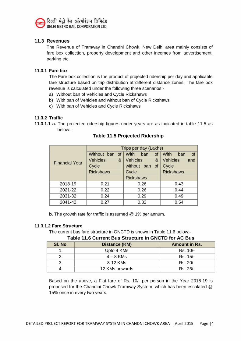
DETAILED PROJECT REPORT FOR TRAMWAY SYSTEM IN CHANDNI CHOWK AREA April 2015 Page |4
11.3 Revenues The Revenue of Tramway in Chandni Chowk, New Delhi area mainly consists of fare box collection, property development and other incomes from advertisement, parking etc.
11.3.1 Fare box The Fare box collection is the product of projected ridership per day and applicable fare structure based on trip distribution at different distance zones. The fare box revenue is calculated under the following three scenarios:- a) Without ban of Vehicles and Cycle Rickshaws b) With ban of Vehicles and without ban of Cycle Rickshaws c) With ban of Vehicles and Cycle Rickshaws
11.3.2 Traffic 11.3.1.1 a. The projected ridership figures under years are as indicated in table 11.5 as
below: - Table 11.5 Projected Ridership
Financial Year
Trips per day (Lakhs) Without ban of Vehicles & Cycle Rickshaws
With ban of Vehicles & without ban of Cycle Rickshaws
With ban of Vehicles and Cycle Rickshaws
2018-19 0.21 0.26 0.43 2021-22 0.22 0.26 0.44 2031-32 0.24 0.29 0.49 2041-42 0.27 0.32 0.54
b. The growth rate for traffic is assumed @ 1% per annum.
11.3.1.2 Fare Structure
The current bus fare structure in GNCTD is shown in Table 11.6 below:- Table 11.6 Current Bus Structure in GNCTD for AC Bus
Sl. No. Distance (KM) Amount in Rs. 1. Upto 4 KMs Rs. 10/- 2. 4 – 8 KMs Rs. 15/- 3. 8-12 KMs Rs. 20/- 4. 12 KMs onwards Rs. 25/-
Based on the above, a Flat fare of Rs. 10/- per person in the Year 2018-19 is proposed for the Chandini Chowk Tramway System, which has been escalated @ 15% once in every two years.
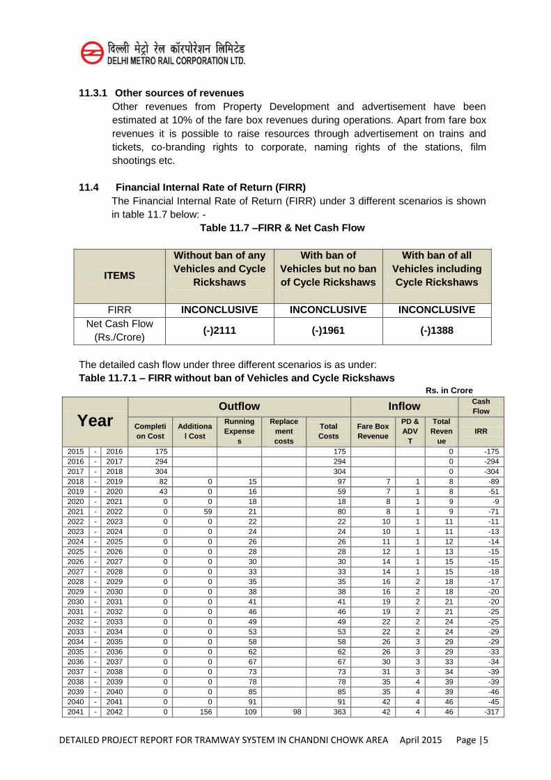
DETAILED PROJECT REPORT FOR TRAMWAY SYSTEM IN CHANDNI CHOWK AREA April 2015 Page |5
11.3.1 Other sources of revenues Other revenues from Property Development and advertisement have been estimated at 10% of the fare box revenues during operations. Apart from fare box revenues it is possible to raise resources through advertisement on trains and tickets, co-branding rights to corporate, naming rights of the stations, film shootings etc.
11.4 Financial Internal Rate of Return (FIRR) The Financial Internal Rate of Return (FIRR) under 3 different scenarios is shown
in table 11.7 below: - Table 11.7 –FIRR & Net Cash Flow
ITEMS
Without ban of any Vehicles and Cycle
Rickshaws
With ban of Vehicles but no ban of Cycle Rickshaws
With ban of all Vehicles including Cycle Rickshaws
FIRR INCONCLUSIVE INCONCLUSIVE INCONCLUSIVE
Net Cash Flow (Rs./Crore)
(-)2111 (-)1961 (-)1388
The detailed cash flow under three different scenarios is as under: Table 11.7.1 – FIRR without ban of Vehicles and Cycle Rickshaws
Rs. in Crore
Year Outflow Inflow Cash
Flow
Completion Cost
Additional Cost
Running Expense
s
Replacement costs
Total Costs
Fare Box Revenue
PD & ADV
T
Total Reven
ue IRR
2015 - 2016 175 175 0 -175 2016 - 2017 294 294 0 -294 2017 - 2018 304 304 0 -304 2018 - 2019 82 0 15 97 7 1 8 -89 2019 - 2020 43 0 16 59 7 1 8 -51 2020 - 2021 0 0 18 18 8 1 9 -9 2021 - 2022 0 59 21 80 8 1 9 -71 2022 - 2023 0 0 22 22 10 1 11 -11 2023 - 2024 0 0 24 24 10 1 11 -13 2024 - 2025 0 0 26 26 11 1 12 -14 2025 - 2026 0 0 28 28 12 1 13 -15 2026 - 2027 0 0 30 30 14 1 15 -15 2027 - 2028 0 0 33 33 14 1 15 -18 2028 - 2029 0 0 35 35 16 2 18 -17 2029 - 2030 0 0 38 38 16 2 18 -20 2030 - 2031 0 0 41 41 19 2 21 -20 2031 - 2032 0 0 46 46 19 2 21 -25 2032 - 2033 0 0 49 49 22 2 24 -25 2033 - 2034 0 0 53 53 22 2 24 -29 2034 - 2035 0 0 58 58 26 3 29 -29 2035 - 2036 0 0 62 62 26 3 29 -33 2036 - 2037 0 0 67 67 30 3 33 -34 2037 - 2038 0 0 73 73 31 3 34 -39 2038 - 2039 0 0 78 78 35 4 39 -39 2039 - 2040 0 0 85 85 35 4 39 -46 2040 - 2041 0 0 91 91 42 4 46 -45 2041 - 2042 0 156 109 98 363 42 4 46 -317
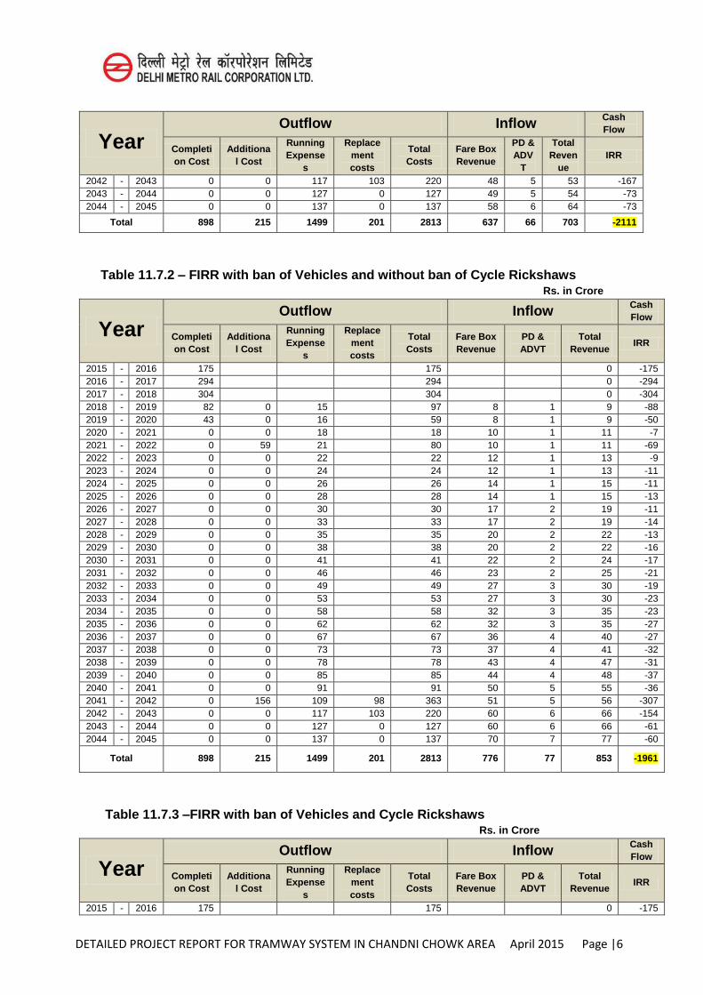
DETAILED PROJECT REPORT FOR TRAMWAY SYSTEM IN CHANDNI CHOWK AREA April 2015 Page |6
Year Outflow Inflow Cash
Flow
Completion Cost
Additional Cost
Running Expense
s
Replacement costs
Total Costs
Fare Box Revenue
PD & ADV
T
Total Reven
ue IRR
2042 - 2043 0 0 117 103 220 48 5 53 -167 2043 - 2044 0 0 127 0 127 49 5 54 -73 2044 - 2045 0 0 137 0 137 58 6 64 -73
Total 898 215 1499 201 2813 637 66 703 -2111
Table 11.7.2 – FIRR with ban of Vehicles and without ban of Cycle Rickshaws Rs. in Crore
Year Outflow Inflow Cash
Flow
Completion Cost
Additional Cost
Running Expense
s
Replacement costs
Total Costs
Fare Box Revenue
PD & ADVT
Total Revenue
IRR
2015 - 2016 175 175 0 -175 2016 - 2017 294 294 0 -294 2017 - 2018 304 304 0 -304 2018 - 2019 82 0 15 97 8 1 9 -88 2019 - 2020 43 0 16 59 8 1 9 -50 2020 - 2021 0 0 18 18 10 1 11 -7 2021 - 2022 0 59 21 80 10 1 11 -69 2022 - 2023 0 0 22 22 12 1 13 -9 2023 - 2024 0 0 24 24 12 1 13 -11 2024 - 2025 0 0 26 26 14 1 15 -11 2025 - 2026 0 0 28 28 14 1 15 -13 2026 - 2027 0 0 30 30 17 2 19 -11 2027 - 2028 0 0 33 33 17 2 19 -14 2028 - 2029 0 0 35 35 20 2 22 -13 2029 - 2030 0 0 38 38 20 2 22 -16 2030 - 2031 0 0 41 41 22 2 24 -17 2031 - 2032 0 0 46 46 23 2 25 -21 2032 - 2033 0 0 49 49 27 3 30 -19 2033 - 2034 0 0 53 53 27 3 30 -23 2034 - 2035 0 0 58 58 32 3 35 -23 2035 - 2036 0 0 62 62 32 3 35 -27 2036 - 2037 0 0 67 67 36 4 40 -27 2037 - 2038 0 0 73 73 37 4 41 -32 2038 - 2039 0 0 78 78 43 4 47 -31 2039 - 2040 0 0 85 85 44 4 48 -37 2040 - 2041 0 0 91 91 50 5 55 -36 2041 - 2042 0 156 109 98 363 51 5 56 -307 2042 - 2043 0 0 117 103 220 60 6 66 -154 2043 - 2044 0 0 127 0 127 60 6 66 -61 2044 - 2045 0 0 137 0 137 70 7 77 -60
Total 898 215 1499 201 2813 776 77 853 -1961
Table 11.7.3 –FIRR with ban of Vehicles and Cycle Rickshaws
Rs. in Crore
Year Outflow Inflow Cash
Flow
Completion Cost
Additional Cost
Running Expense
s
Replacement costs
Total Costs
Fare Box Revenue
PD & ADVT
Total Revenue
IRR
2015 - 2016 175 175 0 -175
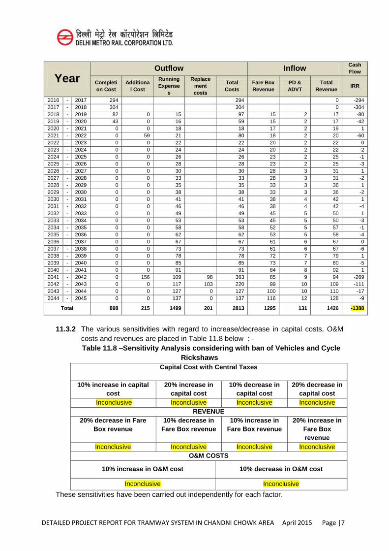
DETAILED PROJECT REPORT FOR TRAMWAY SYSTEM IN CHANDNI CHOWK AREA April 2015 Page |7
Year Outflow Inflow Cash
Flow
Completion Cost
Additional Cost
Running Expense
s
Replacement costs
Total Costs
Fare Box Revenue
PD & ADVT
Total Revenue
IRR
2016 - 2017 294 294 0 -294 2017 - 2018 304 304 0 -304 2018 - 2019 82 0 15 97 15 2 17 -80 2019 - 2020 43 0 16 59 15 2 17 -42 2020 - 2021 0 0 18 18 17 2 19 1 2021 - 2022 0 59 21 80 18 2 20 -60 2022 - 2023 0 0 22 22 20 2 22 0 2023 - 2024 0 0 24 24 20 2 22 -2 2024 - 2025 0 0 26 26 23 2 25 -1 2025 - 2026 0 0 28 28 23 2 25 -3 2026 - 2027 0 0 30 30 28 3 31 1 2027 - 2028 0 0 33 33 28 3 31 -2 2028 - 2029 0 0 35 35 33 3 36 1 2029 - 2030 0 0 38 38 33 3 36 -2 2030 - 2031 0 0 41 41 38 4 42 1 2031 - 2032 0 0 46 46 38 4 42 -4 2032 - 2033 0 0 49 49 45 5 50 1 2033 - 2034 0 0 53 53 45 5 50 -3 2034 - 2035 0 0 58 58 52 5 57 -1 2035 - 2036 0 0 62 62 53 5 58 -4 2036 - 2037 0 0 67 67 61 6 67 0 2037 - 2038 0 0 73 73 61 6 67 -6 2038 - 2039 0 0 78 78 72 7 79 1 2039 - 2040 0 0 85 85 73 7 80 -5 2040 - 2041 0 0 91 91 84 8 92 1 2041 - 2042 0 156 109 98 363 85 9 94 -269 2042 - 2043 0 0 117 103 220 99 10 109 -111 2043 - 2044 0 0 127 0 127 100 10 110 -17 2044 - 2045 0 0 137 0 137 116 12 128 -9
Total 898 215 1499 201 2813 1295 131 1426 -1388
11.3.2 The various sensitivities with regard to increase/decrease in capital costs, O&M
costs and revenues are placed in Table 11.8 below : - Table 11.8 –Sensitivity Analysis considering with ban of Vehicles and Cycle
Rickshaws Capital Cost with Central Taxes
10% increase in capital
cost 20% increase in
capital cost 10% decrease in
capital cost 20% decrease in
capital cost Inconclusive Inconclusive Inconclusive Inconclusive
REVENUE 20% decrease in Fare
Box revenue 10% decrease in
Fare Box revenue 10% increase in
Fare Box revenue 20% increase in
Fare Box revenue
Inconclusive Inconclusive Inconclusive Inconclusive O&M COSTS
10% increase in O&M cost 10% decrease in O&M cost
Inconclusive Inconclusive
These sensitivities have been carried out independently for each factor.
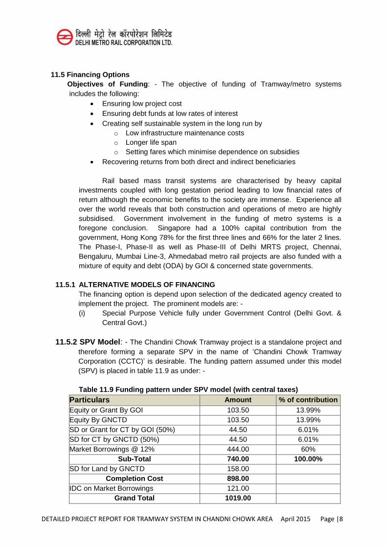
DETAILED PROJECT REPORT FOR TRAMWAY SYSTEM IN CHANDNI CHOWK AREA April 2015 Page |8
11.5 Financing Options
Objectives of Funding: - The objective of funding of Tramway/metro systems includes the following:
Ensuring low project cost Ensuring debt funds at low rates of interest Creating self sustainable system in the long run by
o Low infrastructure maintenance costs o Longer life span o Setting fares which minimise dependence on subsidies
Recovering returns from both direct and indirect beneficiaries
Rail based mass transit systems are characterised by heavy capital investments coupled with long gestation period leading to low financial rates of return although the economic benefits to the society are immense. Experience all over the world reveals that both construction and operations of metro are highly subsidised. Government involvement in the funding of metro systems is a foregone conclusion. Singapore had a 100% capital contribution from the government, Hong Kong 78% for the first three lines and 66% for the later 2 lines. The Phase-I, Phase-II as well as Phase-III of Delhi MRTS project, Chennai, Bengaluru, Mumbai Line-3, Ahmedabad metro rail projects are also funded with a mixture of equity and debt (ODA) by GOI & concerned state governments.
11.5.1 ALTERNATIVE MODELS OF FINANCING The financing option is depend upon selection of the dedicated agency created to implement the project. The prominent models are: - (i) Special Purpose Vehicle fully under Government Control (Delhi Govt. &
Central Govt.)
11.5.2 SPV Model: - The Chandini Chowk Tramway project is a standalone project and therefore forming a separate SPV in the name of ‘Chandini Chowk Tramway Corporation (CCTC)’ is desirable. The funding pattern assumed under this model (SPV) is placed in table 11.9 as under: -
Table 11.9 Funding pattern under SPV model (with central taxes)
Particulars Amount % of contribution Equity or Grant By GOI 103.50 13.99% Equity By GNCTD 103.50 13.99% SD or Grant for CT by GOI (50%) 44.50 6.01% SD for CT by GNCTD (50%) 44.50 6.01% Market Borrowings @ 12% 444.00 60%
Sub-Total 740.00 100.00% SD for Land by GNCTD 158.00
Completion Cost 898.00
IDC on Market Borrowings 121.00
Grand Total 1019.00
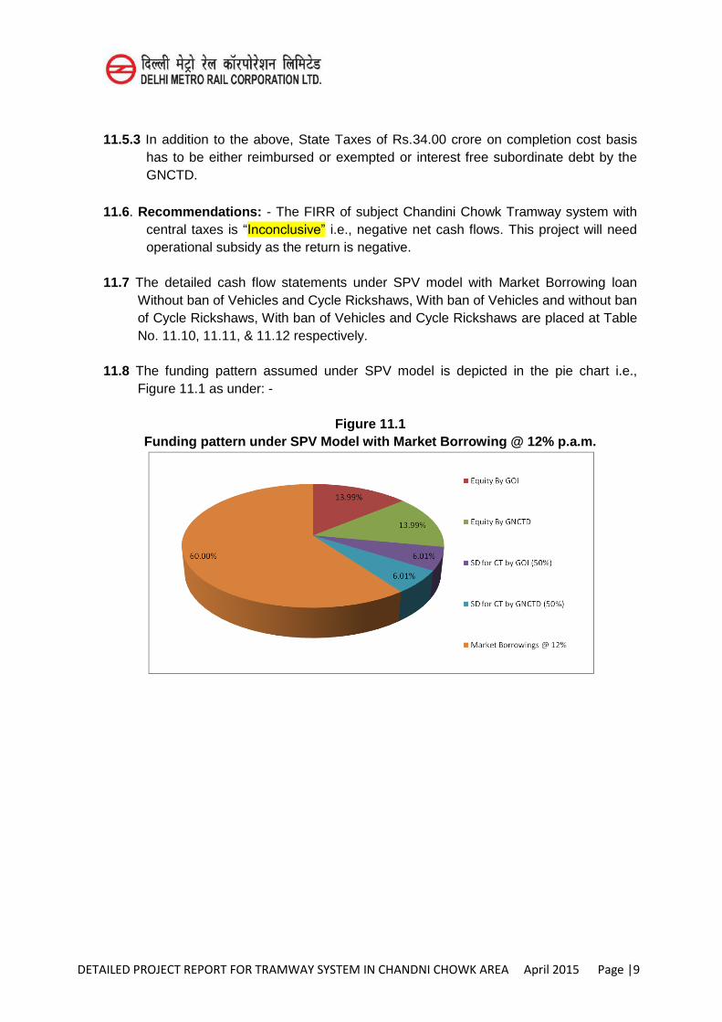
DETAILED PROJECT REPORT FOR TRAMWAY SYSTEM IN CHANDNI CHOWK AREA April 2015 Page |9
11.5.3 In addition to the above, State Taxes of Rs.34.00 crore on completion cost basis
has to be either reimbursed or exempted or interest free subordinate debt by the GNCTD.
11.6. Recommendations: - The FIRR of subject Chandini Chowk Tramway system with
central taxes is “Inconclusive” i.e., negative net cash flows. This project will need operational subsidy as the return is negative.
11.7 The detailed cash flow statements under SPV model with Market Borrowing loan
Without ban of Vehicles and Cycle Rickshaws, With ban of Vehicles and without ban of Cycle Rickshaws, With ban of Vehicles and Cycle Rickshaws are placed at Table No. 11.10, 11.11, & 11.12 respectively.
11.8 The funding pattern assumed under SPV model is depicted in the pie chart i.e.,
Figure 11.1 as under: -
Figure 11.1 Funding pattern under SPV Model with Market Borrowing @ 12% p.a.m.
DETAILED PROJECT REPORT FOR TRAMWAY SYSTEM IN CHANDNI CHOWK AREA April 2015 Page |1
CHAPTER 12
ECONOMIC APPRAISAL
12.1 Introduction
Economic benefits are social and environmental benefits which are quantified and then converted into money cost and discounted against the cost of construction and maintenance for deriving Economic Internal Rate of Return (EIRR). When actual revenue earned from fare collection, advertisement and property development are discounted against construction and maintenance cost, interest (to be paid) and depreciation cost, Financial Internal rate of Return (FIRR) is obtained. Therefore, EIRR is viewed from socio-economic angle while FIRR is an indicator of pure financial profitability and viability of any project.
12.1.1 Economic appraisal of a project starts from quantification of measurable economic benefits in economic money values, which are basically the savings of resource cost due to implementation of the project. Economic savings are derived from the difference of the cost of the same benefit components under ‘with’ and ‘without’
project.
In highway construction projects, ‘without’ is taken as “base case” and ‘with’ implies
‘alternative case’. In ‘alternative case’ a portion of traffic on the road is diverted to a
new road which is estimated first. Then the difference between maintenance & construction cost for ‘base case’ and for ‘alternative case’ which is known as relative road agency cost (RAC) is derived. Difference between road user cost for ‘base case’
and of ‘alternative case’ is also derived which is known as relative road user cost
(RUC). Difference between RAC and RUC calculated for each year generates net benefit stream. Economic indicators (EIRR, BC Ratio, NPV) are the obtained.
In this tramways projects, same principal is followed but procedure is slightly different. Here, diverted traffic is nothing but the passengers shifted from road based modes to tram. Travel time saving is the difference between time which would be taking on tram and other road based transports for same distance. Fuel cost saving is the difference between the cost of the fuel burnt on road based modes by the shifted passengers and the energy cost of running the tram which is a part of the maintenance cost. Thus benefits are directly obtained by correlating with them with the passenger km (ridership and average trip length is multiplied to get passenger km). As is done in highway projects, net benefit is obtained by subtracting the cost of the project (incurred for construction (capital) and maintenance (recurring) costs for the tram line) from the benefits derived from pass km savings in each year. The net
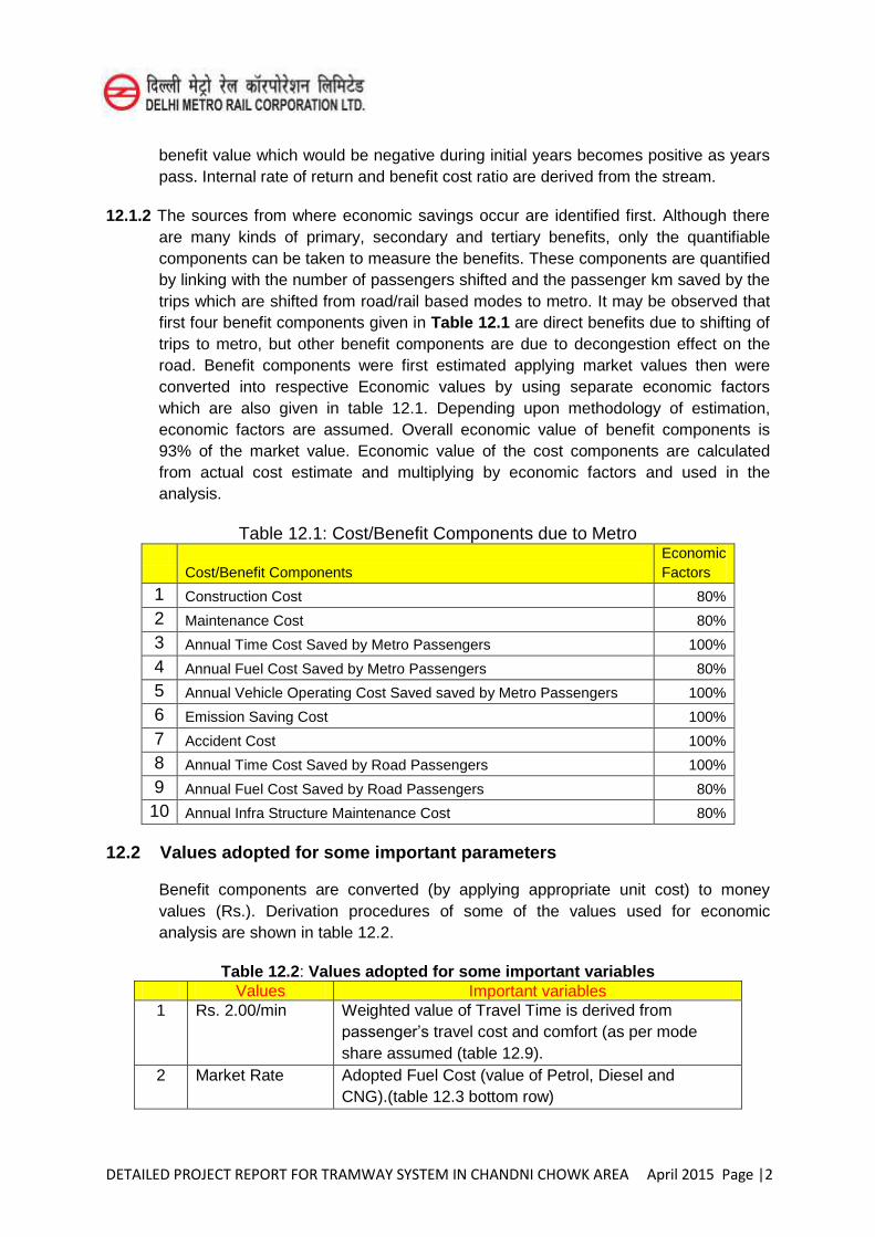
DETAILED PROJECT REPORT FOR TRAMWAY SYSTEM IN CHANDNI CHOWK AREA April 2015 Page |2
benefit value which would be negative during initial years becomes positive as years pass. Internal rate of return and benefit cost ratio are derived from the stream.
12.1.2 The sources from where economic savings occur are identified first. Although there are many kinds of primary, secondary and tertiary benefits, only the quantifiable components can be taken to measure the benefits. These components are quantified by linking with the number of passengers shifted and the passenger km saved by the trips which are shifted from road/rail based modes to metro. It may be observed that first four benefit components given in Table 12.1 are direct benefits due to shifting of trips to metro, but other benefit components are due to decongestion effect on the road. Benefit components were first estimated applying market values then were converted into respective Economic values by using separate economic factors which are also given in table 12.1. Depending upon methodology of estimation, economic factors are assumed. Overall economic value of benefit components is 93% of the market value. Economic value of the cost components are calculated from actual cost estimate and multiplying by economic factors and used in the analysis.
Table 12.1: Cost/Benefit Components due to Metro
Cost/Benefit Components Economic Factors
1 Construction Cost 80%
2 Maintenance Cost 80%
3 Annual Time Cost Saved by Metro Passengers 100%
4 Annual Fuel Cost Saved by Metro Passengers 80%
5 Annual Vehicle Operating Cost Saved saved by Metro Passengers 100%
6 Emission Saving Cost 100%
7 Accident Cost 100%
8 Annual Time Cost Saved by Road Passengers 100%
9 Annual Fuel Cost Saved by Road Passengers 80%
10 Annual Infra Structure Maintenance Cost 80%
12.2 Values adopted for some important parameters
Benefit components are converted (by applying appropriate unit cost) to money values (Rs.). Derivation procedures of some of the values used for economic analysis are shown in table 12.2.
Table 12.2: Values adopted for some important variables Values Important variables 1 Rs. 2.00/min Weighted value of Travel Time is derived from
passenger’s travel cost and comfort (as per mode share assumed (table 12.9).
2 Market Rate Adopted Fuel Cost (value of Petrol, Diesel and CNG).(table 12.3 bottom row)
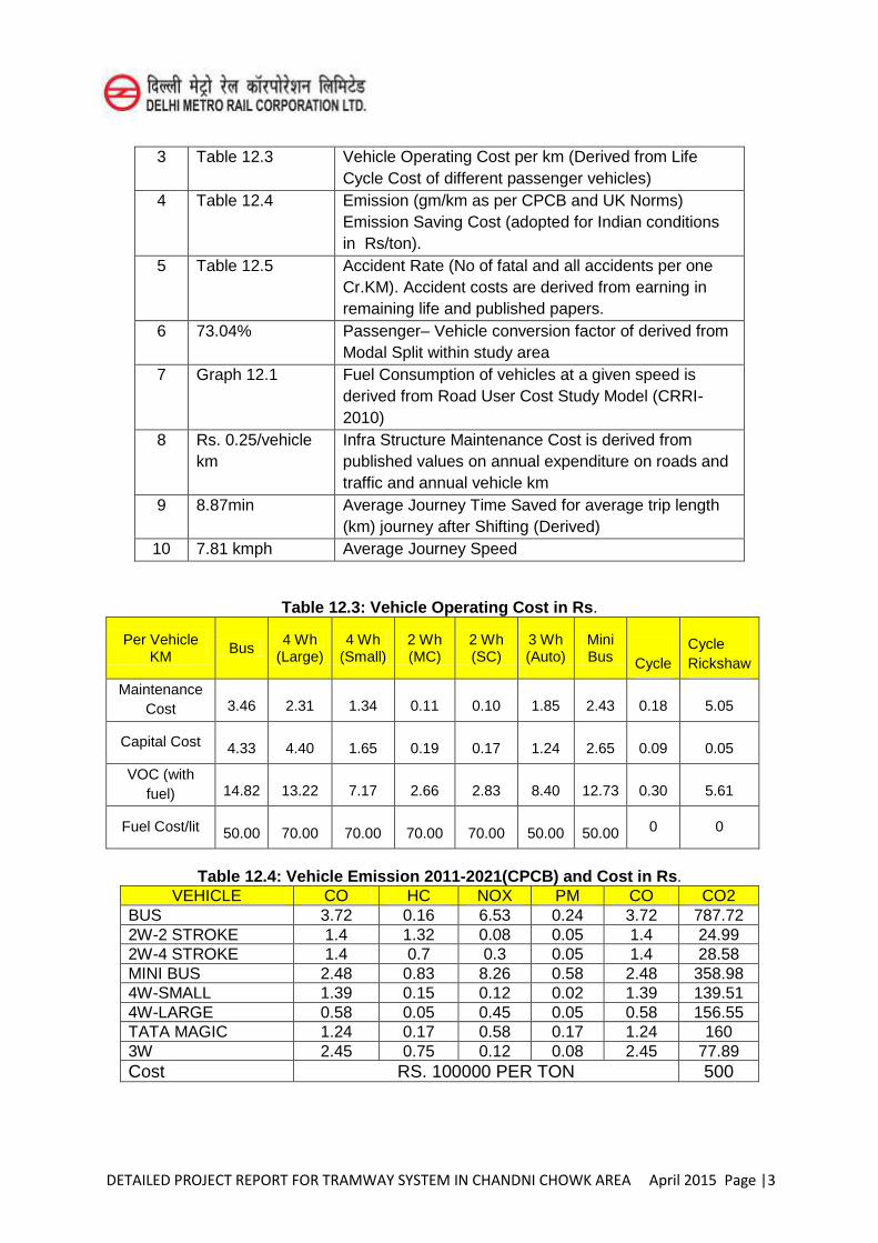
DETAILED PROJECT REPORT FOR TRAMWAY SYSTEM IN CHANDNI CHOWK AREA April 2015 Page |3
3 Table 12.3 Vehicle Operating Cost per km (Derived from Life Cycle Cost of different passenger vehicles)
4 Table 12.4 Emission (gm/km as per CPCB and UK Norms) Emission Saving Cost (adopted for Indian conditions in Rs/ton).
5 Table 12.5 Accident Rate (No of fatal and all accidents per one Cr.KM). Accident costs are derived from earning in remaining life and published papers.
6 73.04% Passenger– Vehicle conversion factor of derived from Modal Split within study area
7 Graph 12.1 Fuel Consumption of vehicles at a given speed is derived from Road User Cost Study Model (CRRI-2010)
8 Rs. 0.25/vehicle km
Infra Structure Maintenance Cost is derived from published values on annual expenditure on roads and traffic and annual vehicle km
9 8.87min Average Journey Time Saved for average trip length (km) journey after Shifting (Derived)
10 7.81 kmph Average Journey Speed
Table 12.3: Vehicle Operating Cost in Rs.
Per Vehicle KM
Bus 4 Wh
(Large) 4 Wh
(Small) 2 Wh (MC)
2 Wh (SC)
3 Wh (Auto)
Mini Bus Cycle
Cycle Rickshaw
Maintenance Cost 3.46 2.31 1.34 0.11 0.10 1.85 2.43 0.18 5.05
Capital Cost 4.33 4.40 1.65 0.19 0.17 1.24 2.65 0.09 0.05
VOC (with fuel) 14.82 13.22 7.17 2.66 2.83 8.40 12.73 0.30 5.61
Fuel Cost/lit 50.00 70.00 70.00 70.00 70.00 50.00 50.00 0 0
Table 12.4: Vehicle Emission 2011-2021(CPCB) and Cost in Rs. VEHICLE CO HC NOX PM CO CO2
BUS 3.72 0.16 6.53 0.24 3.72 787.72 2W-2 STROKE 1.4 1.32 0.08 0.05 1.4 24.99 2W-4 STROKE 1.4 0.7 0.3 0.05 1.4 28.58 MINI BUS 2.48 0.83 8.26 0.58 2.48 358.98 4W-SMALL 1.39 0.15 0.12 0.02 1.39 139.51 4W-LARGE 0.58 0.05 0.45 0.05 0.58 156.55 TATA MAGIC 1.24 0.17 0.58 0.17 1.24 160 3W 2.45 0.75 0.12 0.08 2.45 77.89 Cost RS. 100000 PER TON 500
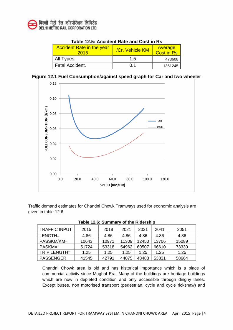
DETAILED PROJECT REPORT FOR TRAMWAY SYSTEM IN CHANDNI CHOWK AREA April 2015 Page |4
Table 12.5: Accident Rate and Cost in Rs Accident Rate in the year
2015 /Cr. Vehicle KM Average Cost in Rs
All Types. 1.5 473608
Fatal Accident. 0.1 1361245
Figure 12.1 Fuel Consumption/against speed graph for Car and two wheeler
Traffic demand estimates for Chandni Chowk Tramways used for economic analysis are given in table 12.6
Table 12.6: Summary of the Ridership
TRAFFIC INPUT 2015 2018 2021 2031 2041 2051 LENGTH= 4.86 4.86 4.86 4.86 4.86 4.86 PASSKM/KM= 10643 10971 11309 12450 13706 15089 PASKM= 51724 53318 54962 60507 66610 73330 TRIP LENGTH= 1.25 1.25 1.25 1.25 1.25 1.25 PASSENGER 41545 42791 44075 48483 53331 58664
Chandni Chowk area is old and has historical importance which is a place of commercial activity since Mughal Era. Many of the buildings are heritage buildings which are now in depleted condition and only accessible through dinghy lanes. Except buses, non motorised transport (pedestrian, cycle and cycle rickshaw) and
0.00
0.02
0.04
0.06
0.08
0.10
0.12
0.0 20.0 40.0 60.0 80.0 100.0 120.0
FUEL
CO
NSU
MP
TIO
N (
l/km
)
SPEED (KM/HR)
CAR
2WH
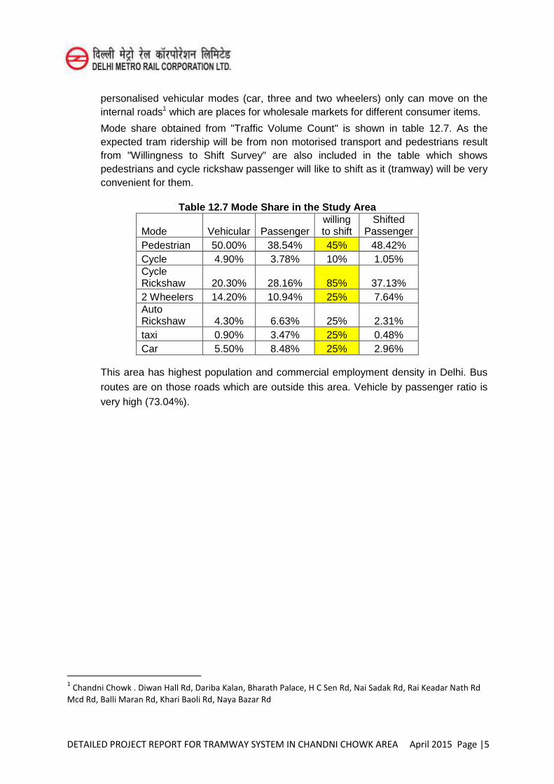
DETAILED PROJECT REPORT FOR TRAMWAY SYSTEM IN CHANDNI CHOWK AREA April 2015 Page |5
personalised vehicular modes (car, three and two wheelers) only can move on the internal roads1 which are places for wholesale markets for different consumer items.
Mode share obtained from "Traffic Volume Count" is shown in table 12.7. As the expected tram ridership will be from non motorised transport and pedestrians result from "Willingness to Shift Survey" are also included in the table which shows pedestrians and cycle rickshaw passenger will like to shift as it (tramway) will be very convenient for them.
Table 12.7 Mode Share in the Study Area
Mode Vehicular Passenger willing to shift
Shifted Passenger
Pedestrian 50.00% 38.54% 45% 48.42% Cycle 4.90% 3.78% 10% 1.05% Cycle Rickshaw 20.30% 28.16% 85% 37.13% 2 Wheelers 14.20% 10.94% 25% 7.64% Auto Rickshaw 4.30% 6.63% 25% 2.31% taxi 0.90% 3.47% 25% 0.48% Car 5.50% 8.48% 25% 2.96%
This area has highest population and commercial employment density in Delhi. Bus routes are on those roads which are outside this area. Vehicle by passenger ratio is very high (73.04%).
1 Chandni Chowk . Diwan Hall Rd, Dariba Kalan, Bharath Palace, H C Sen Rd, Nai Sadak Rd, Rai Keadar Nath Rd
Mcd Rd, Balli Maran Rd, Khari Baoli Rd, Naya Bazar Rd
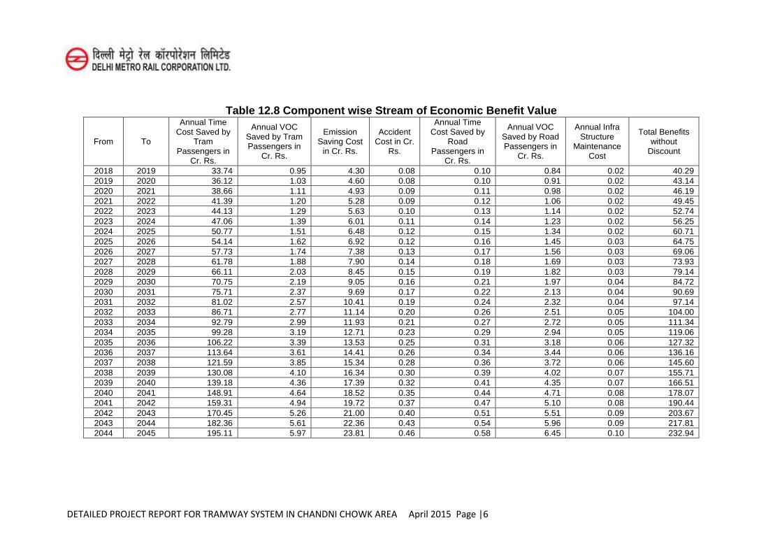
DETAILED PROJECT REPORT FOR TRAMWAY SYSTEM IN CHANDNI CHOWK AREA April 2015 Page |6
Table 12.8 Component wise Stream of Economic Benefit Value
From To
Annual Time Cost Saved by
Tram Passengers in
Cr. Rs.
Annual VOC Saved by Tram Passengers in
Cr. Rs.
Emission Saving Cost
in Cr. Rs.
Accident Cost in Cr.
Rs.
Annual Time Cost Saved by
Road Passengers in
Cr. Rs.
Annual VOC Saved by Road Passengers in
Cr. Rs.
Annual Infra Structure
Maintenance Cost
Total Benefits without
Discount
2018 2019 33.74 0.95 4.30 0.08 0.10 0.84 0.02 40.29 2019 2020 36.12 1.03 4.60 0.08 0.10 0.91 0.02 43.14 2020 2021 38.66 1.11 4.93 0.09 0.11 0.98 0.02 46.19 2021 2022 41.39 1.20 5.28 0.09 0.12 1.06 0.02 49.45 2022 2023 44.13 1.29 5.63 0.10 0.13 1.14 0.02 52.74 2023 2024 47.06 1.39 6.01 0.11 0.14 1.23 0.02 56.25 2024 2025 50.77 1.51 6.48 0.12 0.15 1.34 0.02 60.71 2025 2026 54.14 1.62 6.92 0.12 0.16 1.45 0.03 64.75 2026 2027 57.73 1.74 7.38 0.13 0.17 1.56 0.03 69.06 2027 2028 61.78 1.88 7.90 0.14 0.18 1.69 0.03 73.93 2028 2029 66.11 2.03 8.45 0.15 0.19 1.82 0.03 79.14 2029 2030 70.75 2.19 9.05 0.16 0.21 1.97 0.04 84.72 2030 2031 75.71 2.37 9.69 0.17 0.22 2.13 0.04 90.69 2031 2032 81.02 2.57 10.41 0.19 0.24 2.32 0.04 97.14 2032 2033 86.71 2.77 11.14 0.20 0.26 2.51 0.05 104.00 2033 2034 92.79 2.99 11.93 0.21 0.27 2.72 0.05 111.34 2034 2035 99.28 3.19 12.71 0.23 0.29 2.94 0.05 119.06 2035 2036 106.22 3.39 13.53 0.25 0.31 3.18 0.06 127.32 2036 2037 113.64 3.61 14.41 0.26 0.34 3.44 0.06 136.16 2037 2038 121.59 3.85 15.34 0.28 0.36 3.72 0.06 145.60 2038 2039 130.08 4.10 16.34 0.30 0.39 4.02 0.07 155.71 2039 2040 139.18 4.36 17.39 0.32 0.41 4.35 0.07 166.51 2040 2041 148.91 4.64 18.52 0.35 0.44 4.71 0.08 178.07 2041 2042 159.31 4.94 19.72 0.37 0.47 5.10 0.08 190.44 2042 2043 170.45 5.26 21.00 0.40 0.51 5.51 0.09 203.67 2043 2044 182.36 5.61 22.36 0.43 0.54 5.96 0.09 217.81 2044 2045 195.11 5.97 23.81 0.46 0.58 6.45 0.10 232.94
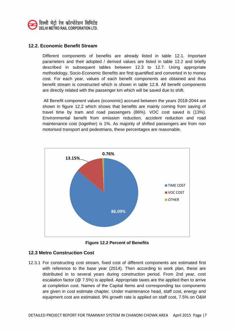
DETAILED PROJECT REPORT FOR TRAMWAY SYSTEM IN CHANDNI CHOWK AREA April 2015 Page |7
12.2. Economic Benefit Stream
Different components of benefits are already listed in table 12.1. Important parameters and their adopted / derived values are listed in table 12.2 and briefly described in subsequent tables between 12.3 to 12.7. Using appropriate methodology, Socio-Economic Benefits are first quantified and converted in to money cost. For each year, values of each benefit components are obtained and thus benefit stream is constructed which is shown in table 12.8. All benefit components are directly related with the passenger km which will be saved due to shift.
All Benefit component values (economic) accrued between the years 2018-2044 are shown in figure 12.2 which shows that benefits are mainly coming from saving of travel time by tram and road passengers (86%). VOC cost saved is (13%). Environmental benefit from emission reduction, accident reduction and road maintenance cost (together) is 1%. As majority of shifted passengers are from non motorised transport and pedestrians, these percentages are reasonable.
Figure 12.2 Percent of Benefits
12.3 Metro Construction Cost
12.3.1 For constructing cost stream, fixed cost of different components are estimated first with reference to the base year (2014). Then according to work plan, these are distributed in to several years during construction period. From 2nd year, cost escalation factor (@ 7.5%) is applied. Appropriate taxes are the applied then to arrive at completion cost. Names of the Capital Items and corresponding tax components are given in cost estimate chapter. Under maintenance head, staff cost, energy and equipment cost are estimated. 9% growth rate is applied on staff cost, 7.5% on O&M
86.09%
13.15% 0.76%
TIME COST
VOC COST
OTHER
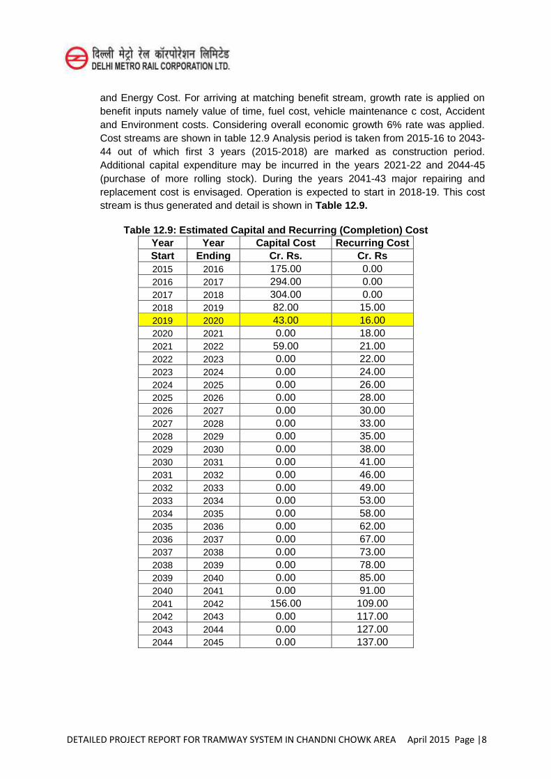
DETAILED PROJECT REPORT FOR TRAMWAY SYSTEM IN CHANDNI CHOWK AREA April 2015 Page |8
and Energy Cost. For arriving at matching benefit stream, growth rate is applied on benefit inputs namely value of time, fuel cost, vehicle maintenance c cost, Accident and Environment costs. Considering overall economic growth 6% rate was applied. Cost streams are shown in table 12.9 Analysis period is taken from 2015-16 to 2043-44 out of which first 3 years (2015-2018) are marked as construction period. Additional capital expenditure may be incurred in the years 2021-22 and 2044-45 (purchase of more rolling stock). During the years 2041-43 major repairing and replacement cost is envisaged. Operation is expected to start in 2018-19. This cost stream is thus generated and detail is shown in Table 12.9.
Table 12.9: Estimated Capital and Recurring (Completion) Cost Year Year Capital Cost Recurring Cost Start Ending Cr. Rs. Cr. Rs 2015 2016 175.00 0.00 2016 2017 294.00 0.00 2017 2018 304.00 0.00 2018 2019 82.00 15.00 2019 2020 43.00 16.00 2020 2021 0.00 18.00 2021 2022 59.00 21.00 2022 2023 0.00 22.00 2023 2024 0.00 24.00 2024 2025 0.00 26.00 2025 2026 0.00 28.00 2026 2027 0.00 30.00 2027 2028 0.00 33.00 2028 2029 0.00 35.00 2029 2030 0.00 38.00 2030 2031 0.00 41.00 2031 2032 0.00 46.00 2032 2033 0.00 49.00 2033 2034 0.00 53.00 2034 2035 0.00 58.00 2035 2036 0.00 62.00 2036 2037 0.00 67.00 2037 2038 0.00 73.00 2038 2039 0.00 78.00 2039 2040 0.00 85.00 2040 2041 0.00 91.00 2041 2042 156.00 109.00 2042 2043 0.00 117.00 2043 2044 0.00 127.00 2044 2045 0.00 137.00
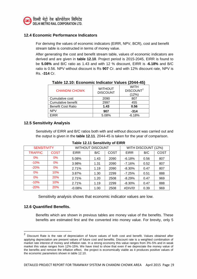
DETAILED PROJECT REPORT FOR TRAMWAY SYSTEM IN CHANDNI CHOWK AREA April 2015 Page |9
12.4 Economic Performance Indicators
For deriving the values of economic indicators (EIRR, NPV, BCR), cost and benefit stream table is constructed in terms of money value.
After generating the cost and benefit stream table, values of economic indicators are derived and are given in table 12.10. Project period is 2015-2045, EIRR is found to be 5.08% and B/C ratio as 1.43 and with 12 % discount, EIRR is -6.18% and B/C ratio is 0.56. NPV without discount is Rs 907 Cr. and with 12% discount rate, NPV is Rs. -314 Cr.
Table 12.10: Economic Indicator Values (2044-45)
CHANDNI CHOWK WITHOUT DISCOUNT
WITH DISCOUNT2
(12%) Cumulative cost 2090 807 Cumulative benefit 2997 455 Benefit Cost Ratio 1.43 0.56 NPV 907 -314 EIRR 5.08% -6.18%
12.5 Sensitivity Analysis
Sensitivity of EIRR and B/C ratios both with and without discount was carried out and the output is given in the table 12.11. 2044-45 is taken for the year of comparison.
Table 12.11 Sensitivity of EIRR SENSITIVITY WITHOUT DISCOUNT WITH DISCOUNT (12%)
TRAFFIC COST EIRR B/C COST EIRR B/C COST
0% 0% 5.08% 1.43 2090 -6.18% 0.56 807 -10% 0% 3.98% 1.31 2090 -7.16% 0.52 807 -20% 0% 2.71% 1.19 2090 -8.30% 0.47 807 0% 10% 3.87% 1.30 2299 -7.25% 0.51 888 0% 20% 2.71% 1.20 2508 -8.29% 0.47 969
-10% 10% 2.71% 1.19 2299 -8.30% 0.47 888 -20% 20% -0.08% 1.00 2508 #DIV/0! 0.39 969
Sensitivity analysis shows that economic indicator values are low.
12.6 Quantified Benefits.
Benefits which are shown in previous tables are money value of the benefits. These benefits are estimated first and the converted into money value. For brevity, only 5
2 Discount Rate is the rate of depreciation of future values of both cost and benefit. Values obtained after applying depreciation are present values of future cost and benefits. Discount rate is a weighted combination of market rate interest of money and inflation rate. In a strong economy this value ranges from 3%-5% and in weak market this value ranges from 12%-15%. We have tried to show that even if we depreciate the money value of the benefits and remove the inflation effect, the project is economically viable as it produces positive values of the economic parameters shown in table 12.10.
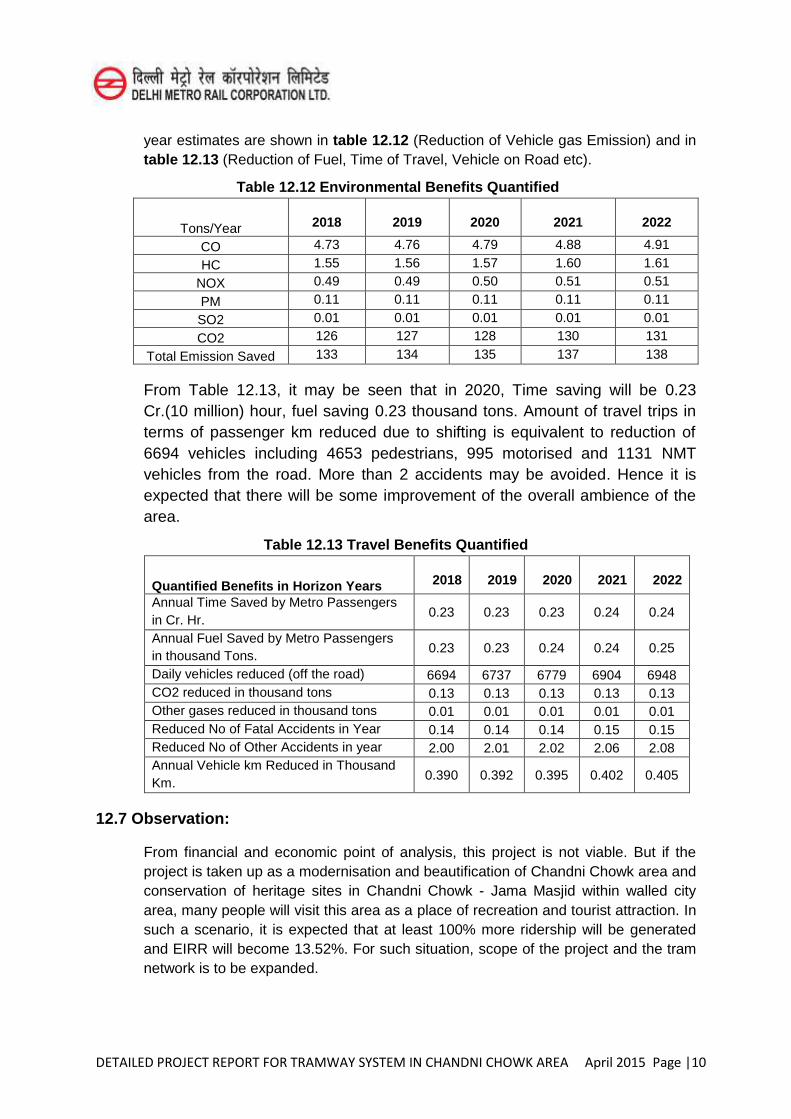
DETAILED PROJECT REPORT FOR TRAMWAY SYSTEM IN CHANDNI CHOWK AREA April 2015 Page |10
year estimates are shown in table 12.12 (Reduction of Vehicle gas Emission) and in table 12.13 (Reduction of Fuel, Time of Travel, Vehicle on Road etc).
Table 12.12 Environmental Benefits Quantified
Tons/Year 2018 2019 2020 2021 2022
CO 4.73 4.76 4.79 4.88 4.91
HC 1.55 1.56 1.57 1.60 1.61
NOX 0.49 0.49 0.50 0.51 0.51
PM 0.11 0.11 0.11 0.11 0.11
SO2 0.01 0.01 0.01 0.01 0.01
CO2 126 127 128 130 131
Total Emission Saved 133 134 135 137 138
From Table 12.13, it may be seen that in 2020, Time saving will be 0.23 Cr.(10 million) hour, fuel saving 0.23 thousand tons. Amount of travel trips in terms of passenger km reduced due to shifting is equivalent to reduction of 6694 vehicles including 4653 pedestrians, 995 motorised and 1131 NMT vehicles from the road. More than 2 accidents may be avoided. Hence it is expected that there will be some improvement of the overall ambience of the area.
Table 12.13 Travel Benefits Quantified
Quantified Benefits in Horizon Years 2018 2019 2020 2021 2022
Annual Time Saved by Metro Passengers in Cr. Hr.
0.23 0.23 0.23 0.24 0.24
Annual Fuel Saved by Metro Passengers in thousand Tons.
0.23 0.23 0.24 0.24 0.25
Daily vehicles reduced (off the road) 6694 6737 6779 6904 6948 CO2 reduced in thousand tons 0.13 0.13 0.13 0.13 0.13 Other gases reduced in thousand tons 0.01 0.01 0.01 0.01 0.01 Reduced No of Fatal Accidents in Year 0.14 0.14 0.14 0.15 0.15 Reduced No of Other Accidents in year 2.00 2.01 2.02 2.06 2.08 Annual Vehicle km Reduced in Thousand Km.
0.390 0.392 0.395 0.402 0.405
12.7 Observation:
From financial and economic point of analysis, this project is not viable. But if the project is taken up as a modernisation and beautification of Chandni Chowk area and conservation of heritage sites in Chandni Chowk - Jama Masjid within walled city area, many people will visit this area as a place of recreation and tourist attraction. In such a scenario, it is expected that at least 100% more ridership will be generated and EIRR will become 13.52%. For such situation, scope of the project and the tram network is to be expanded.
DETAILED PROJECT REPORT FOR TRAMWAY SYSTEM IN CHANDNI CHOWK AREA April 2015 Page |1
CHAPTER- 13
DISASTER MANAGEMENT MEASURES
13.1 INTRODUCTION “Disaster is a crisis that results in massive damage to life and property, uproots the
physical and psychological fabric of the affected communities and outstrips the capacity of the local community to cope with the situation.” Disasters are those situations which cause acute distress to passengers, employees and outsiders and may even be caused by external factors. As per the disaster management act, 2005 "disaster" means a catastrophe, mishap, calamity or grave occurrence in any area, arising from natural or manmade causes, or by accident or negligence which results in substantial loss of life or human suffering or damage to, and destruction of, property, or damage to, or degradation of, environment, and is of such a nature or magnitude as to be beyond the coping capacity of the community of the affected area”. As per world health organisation (who): “Any occurrence that causes damage, economic disruption, loss of human life and deterioration of health and services on a scale sufficient to warrant an extra ordinary response from outside the affected community or area.” A disaster is a tragic event, be it natural or manmade, which brings sudden and immense agony to humanity and disrupts normal life. It causes large scale human suffering due to loss of life, loss of livelihood, damages to property and persons and also brings untold hardships. It may also cause destruction to infrastructure, buildings, communication channels essential services, etc.
13.2 NEED FOR DISASTER MANAGEMENT MEASURES The effect of any disaster spread over in operational area of Tramway is likely to be substantial as the proposed Chandini Chowk Tramway Corporation (CCTC) will deal with thousands of passengers daily in Tramway route, on stoppages and elevated stations. Disaster brings about sudden and immense misery to humanity and disrupts normal human life in its established social and economic patterns. It has the potential to cause large scale human suffering due to loss of life, loss of livelihood, damage to property, injury and hardship to human beings. It may also cause destruction or damage
DETAILED PROJECT REPORT FOR TRAMWAY SYSTEM IN CHANDNI CHOWK AREA April 2015 Page |2
to infrastructure, buildings and communication channels of Tram. Therefore there is an urgent need to provide for an efficient disaster management plan.
13.3 OBJECTIVES:
The main objectives of this Disaster Management Measures are as follows:
Save life and alleviate suffering.
Provide help to stranded passengers and arrange their prompt evacuation.
Instill a sense of security amongst all concerned by providing accurate information.
Protect Tramway property.
Expedite restoration of tramway operation.
Lay down the actions required to be taken by staff in the event of a disaster in Tramway in order to ensure handling of crisis situation in coordinated manner.
To ensure that all officials who are responsible to deal with the situation are thoroughly conversant with their duties and responsibilities in advance. It is important that these officials and workers are adequately trained in anticipation to avoid any kind of confusion and chaos at the time of the actual situation and to enable them to discharge their responsibilities with alertness and promptness.
13.4 LIST OF SERIOUS INCIDENTS REQUIRING USE OF PROVISIONS OF THE
DISASTER MANAGEMENT MEASURES
Metro specific disasters can be classified into two broad categories e.g.: Man-made and Natural.
a. Man Made Disaster
1. Terrorist attack 2. Bomb threat/ Bomb blast 3. Hostage 4. Release of Chemical or biological gas in trains, stations or tunnels 5. Fire in tram buildings, at grade/ elevated infrastructures, power stations, tram
depots etc. 6. Tram accident and tram collision/derailment of a passenger carrying train 7. Sabotage 8. Stampede 9.
b. Natural Disaster 1. Earthquakes

DETAILED PROJECT REPORT FOR TRAMWAY SYSTEM IN CHANDNI CHOWK AREA April 2015 Page |3
2. Floods
13.5 PROVISIONS UNDER DISASTER MANAGEMENT ACT, 2005 A. The National Disaster Management Authority (NDMA)
Establishment of National Disaster Management Authority:-
(1) With effect from such date as the Central Government may, by notification in the Official Gazette appoint in this behalf, there shall be established for the purposes of this Act (The Disaster Management Act, 2005), an authority to be known as the National Disaster Management Authority.
(2) The National Authority shall consist of the Chairperson and such number of other members, not exceeding nine, as may be prescribed by the Central Government and, unless the rules otherwise provide, the National Authority shall consist of the following:-
(a) The Prime Minister of India, who shall be the Chairperson of the National
Authority, ex officio;
(b) Other members, not exceeding nine, to be nominated by the Chairperson of the National Authority.
(3) The Chairperson of the National Authority may designate one of the members
nominated under clause (b) of sub-section (2) to be the Vice- Chairperson of the National Authority.
(4) The term of office and conditions of service of members of the National Authority shall be such as may be prescribed.
B. State Disaster Management Authority:
Establishment of State Disaster Management Authority:-
(1) Every State Government shall, as soon as may be after the issue of the notification under sub-section (1) of section 3, by notification in the Official Gazette, establish a State Disaster Management Authority for the State with such name as may be specified in the notification of the State Government.
(2) A State Authority shall consist of the Chairperson and such number of other members, not exceeding nine, as may be prescribed by the State Government and, unless the rules otherwise provide, the State Authority shall consist of the

DETAILED PROJECT REPORT FOR TRAMWAY SYSTEM IN CHANDNI CHOWK AREA April 2015 Page |4
following members, namely:- The Chief Minister of the State, who shall be Chairperson, ex officio;
(a) Other members, not exceeding eight, to be nominated by the Chairperson of
the State Authority;
(b) The Chairperson of the State Executive Committee, ex officio.
(3) The Chairperson of the State Authority may designate one of the members nominated under clause (b) of sub-section (2) to be the Vice- Chairperson of the State Authority.
(4) The Chairperson of the State Executive Committee shall be the Chief Executive Officer of the State Authority, ex officio: Provided that in the case of a Union territory having Legislative Assembly, except the Union territory of Delhi, the Chief Minister shall be the Chairperson of the Authority established under this section and in case of other Union territories, the Lieutenant Governor or the Administrator shall be the Chairperson of that Authority: Provided further that the Lieutenant Governor of the Union territory of Delhi shall be the Chairperson and the Chief Minister thereof shall be the Vice-Chairperson of the State Authority.
(5) The term of office and conditions of service of members of the State Authority
shall be such as may be prescribed. C. Command & Control at the National, State & District Level
The mechanism to deal with natural as well as manmade crisis already exists and that it has a four tier structure as stated below:-
(1) National Crisis Management Committee (NCMC) under the chairmanship of Cabinet Secretary
(2) Crisis Management Group (CMG) under the chairmanship of Union Home Secretary.
(3) State Level Committee under the chairmanship of Chief Secretary.
(4) District Level Committee under the Chairmanship of District Magistrate.
All agencies of the Government at the National, State and district levels will function in accordance with the guidelines and directions given by these committees.
DETAILED PROJECT REPORT FOR TRAMWAY SYSTEM IN CHANDNI CHOWK AREA April 2015 Page |5
D. Plans by Different Authorities at District Level and their Implementation
Every office of the Government of India and of the State Government at the district level and the local authorities shall, subject to the supervision of the District Authority:- (a) Prepare a disaster management plan setting out the following, namely:-
(i) Provisions for prevention and mitigation measures as provided for in the District
Plan and as is assigned to the department or agency concerned; (ii) Provisions for taking measures relating to capacity-building and preparedness as
laid down in the District Plan; (iii)The response plans and procedures, in the event of, any threatening disaster
situation or disaster;
(b) Coordinate the preparation and the implementation of its plan with those of the other organizations at the district level including local authority, communities and other stakeholders;
(c) Regularly review and update the plan; and
(d) Submit a copy of its disaster management plan, and of any amendment thereto, to the District Authority.
13.6 PROVISIONS AT TRAM STOPPAGES/OTHER INSTALLATIONS
To prevent emergency situations and to handle effectively in case ‘one arises’
there needs to be following provisions for an effective system which can timely detect the threats and help suppress the same.
(A) Fire Detection and Suppression System (B) Smoke Management (C) Environmental Control System (ECS) (D) Track-way Exhaust System (TES) (E) Station Power supply System (F) DG Sets & UPS (G) Lighting System (H) Stop Area Lights (I) Seepage System (J) Water Supply and Drainage System
DETAILED PROJECT REPORT FOR TRAMWAY SYSTEM IN CHANDNI CHOWK AREA April 2015 Page |6
(K) Any other system deemed necessary
The above list is suggestive not exhaustive actual provisioning has to be done based on site conditions and other external and internal factors.
13.7 PREPAREDNESS FOR DISASTER MANAGEMENT
Being a technological complex system worked by new set of staff, with a learning curve to improve and stabilize with time, intensive mock drills for the staff concerned is very essential to train them to become fully conversant with the action required to be taken while handling emergencies. They also need to be trained in appropriate communication skills while addressing passengers during incident management to assure them about their well being seeking their cooperation. Since learning can only be perfected by ‘doing’ the following Mock Drills are considered
essential:
a. Fire Drill b. Rescue of a disabled train c. Detrainment of passengers between stations d. Passenger evacuation from station e. Drill for use of rescue & relief train f. Hot line telephone communication with state disaster management authority.
DETAILED PROJECT REPORT FOR TRAMWAY SYSTEM IN CHANDNI CHOWK AREA April 2015 Page |1
Chapter – 14
DISABLED FRIENDLY FEATURES
14.1 INTRODUCTION
The objective of making this chapter is to create a user-friendly mass transport system in India which can ensure accessibility to persons with disabilities, people travelling with small children or are carrying luggage, as well as people with temporary mobility problems (e.g. a leg in plaster) and the elderly persons.
The design standards for universal access to Public Transport Infrastructure including related facilities and services, information, etc. would benefit people using public transport. The access standards given here are extracted from Indian Roads Congress Code, IRC 103: 2012, Guidelines for Pedestrian Facilities; Model Building Bye-Laws, 2011 and National Building Code, 2005. Central Public Works Department’s (CPWD) “Space
Standards for Barrier Free Built Environment for Disabled and Elderly Persons”, 1998
and 2013 edition (under revision by MoUD), and international best practices / standards Further, it has also been attempted to provide guidelines/ standards for alighting and boarding area, approach to station, car parking area, drop-off and pick-up areas, taxi/auto rickshaw stand, bus stand/stop, footpath (sidewalk), kerb ramp, road intersection, median/pedestrian refuge, traffic signals, subway and foot over bridge etc. to achieve a seamless development around tram stations.
14.2 CONTENT
1. Rail Transport
2. Tramway Station Way finding Signage Automated Kiosks Public Dealing Counters Audio-visual Displays Public Telephones
DETAILED PROJECT REPORT FOR TRAMWAY SYSTEM IN CHANDNI CHOWK AREA April 2015 Page |2
Rest Areas/Seating Tactile Paving - Guiding & Warning Doors Steps & Stairs Handrails Ramps Lifts/Elevators Platform/Stair Lift General and Accessible toilets Drinking Water Units Visual Contrasts Emergency Egress/Evacuation
3. Street Design
Footpath (Sidewalk) Kerb Ramp Road Intersection Median/Pedestrian Refuge Traffic Signals Subway and Foot Over Bridge
4. Alighting and Boarding Area
Approach Car Park Drop-off and Pick-up Areas Taxi/Auto Rickshaw Stand Bus Stand/Stop
14.3 TRAMWAY SYSTEM
1. General Low floor Tram is a highly effective mode of transport. Every tram should contain fully accessible carriages. Staff should be trained in methods of assistance and be at hand on request. Stops for all the tramway should be fully accessible with extra wide turnstiles where
possible alongside wheelchair accessible doorways Staff should be on hand to assist persons with disabilities and elderly to enter or exit
through convenient gates. All the stops for Tramway should be designed to be fully accessible.

DETAILED PROJECT REPORT FOR TRAMWAY SYSTEM IN CHANDNI CHOWK AREA April 2015 Page |3
For persons with hearing impairments, an electronic sign board (digital display) should be displayed on each platform at conspicuous location for all announcements made by the Tramway.
For persons with visual impairments audio system announcing the stop names and door location should be available.
2. Accessible Tram Cars The Tram cars should have the following features:
Tram doors should be at least 900 mm wide; The gap between the car doors and the platform should preferably be less than 12
mm; Identification signage should be provided on the doors of wheelchair accessible
coach If the car door and the platform cannot be at the same level, then at least one car
doors should have apparatus such as a hydraulic lift or pull-out ramp installed in the doorway for wheelchair users.
3. Wheel Chair Space
Space for a wheel chair should be available at the side of the door:- The space should be indicated inside and outside the car by using the international
symbol of access; and Wheel stoppers and ring-strap or other appropriate safety grip should be provided for
wheelchair users.
4. Seats
An appropriate number of designated seats for passengers with disabilities and elderly people should be provided near the doors.
5. Aisles
Aisles should be at least 900 mm wide.
14.4 INFORMATION SIGNS AND ANNOUNCEMENTS
A map of tram routes should be installed. This should be in Braille/raised numbers as well. In each car, there should be an announcement and provision of a visual display of the names of Tramway stops route. This display should be in raised numbers with sharp contrast from the background.

DETAILED PROJECT REPORT FOR TRAMWAY SYSTEM IN CHANDNI CHOWK AREA April 2015 Page |4
14.5 TRAM RAIL STOPPAGE
1. LEVEL APPROACH
Approach route should not have level differences. If the stoppage is not on the same level as the walkway or pathway, it should a ramp.
Walkway surfaces should be non-slip. Approach walkway should have tactile pavements for persons with visual
impairments.
2. STOPPAGE ENTRANCES AND EXITS
These should have a minimum width of 1800mm and is level or ramped.
3. RESERVATION AND INFORMATION COUNTERS
Should have clear floor space of at least 900 mm x 1200 mm in front of the counters;
There should be at least one low counter at a height of 750 mm to 800 mm from the floor with clear knee space of 750 mm high by 900 mm wide by 480 mm deep.
At least one of the counters should have an induction loop unit to aid people with hearing impairments; and
The counters should have pictographic maps indicating all the services offered at the counter and at least one of the counter staff should be sign language literate.
4. TOILET FACILITIES
There should be at least one unisex accessible toilet near to the stoppage.
5. TICKET GATES
At least one of the ticket gates should: Be minimum 900 mm wide to allow a wheelchair user through; and Have a continuous line of guiding paver for people with visual impairments.
6. PLATFORMS
The Platforms should: Have a row of warning paver installed 600mm Have non-slip and level flooring; Have seating areas for people with ambulatory disabilities; Be well illuminated lux level 35 to 40; There should be no gap or difference in level between the tram entry door and
the platform.
DETAILED PROJECT REPORT FOR TRAMWAY SYSTEM IN CHANDNI CHOWK AREA April 2015 Page |5
All platforms should inter-connect by means of accessible routes.
7. WAY FINDING
Way finding references should be available at decision points. Colour can be used to identify routes and provide assistance in locating doors,
walls and hazards. Proper colour contrast between different elements greatly improves visibility for all users and is critical for persons with low vision. For example, colour contrasting of door frames can assist in locating doors, and likewise floors should be contrasted with walls. In addition, furniture should contrast with walls and floors so as not to create an obstacle.
Structural elements such as columns should be colour contrasted or brightly marked so as to be visible to those who may have a visual disability.
Generally, patterns on flooring should be avoided or else should be minimal and small to avoid visual confusion.
In addition to identifying hazards or warnings, tactile floor surfaces can also be used to inform that there is a change in area (e.g. leaving a corridor and entering a boarding area).
Tactile systems should be consistent throughout the building. For example, terminals should not have carpeting in some boarding areas and tile in others as this may create confusion for those who rely on tactile surfaces to guide them to their destination.
Good lighting assists those with a visual disability to see better and allows people who have a hearing impairment to lip read easier. However, care should be taken to properly direct lighting and to use matte finishes on floors, walls and signage, so as not to create glare which may create difficulties for all travellers.
Blinds can be used to adjust lighting levels in areas where the natural lighting changes significantly throughout the day.
8. SIGNAGE
Signs must be clear, concise, and consistent. All travelers need clear information about the purpose and layout of terminals to maintain a sense of direction and independent use of all facilities. Using internationally and nationally established symbols and pictograms with clear lettering and Braille ensures universal accessibility cutting across regional/cultural and language barriers. A cohesive information and signage system can provide visual (e.g. signs, notice boards), audible (e.g. public address and security systems, induction loops, telephones, and infrared devices), and/ or tactile information (e.g. signs with embossed lettering or Braille).
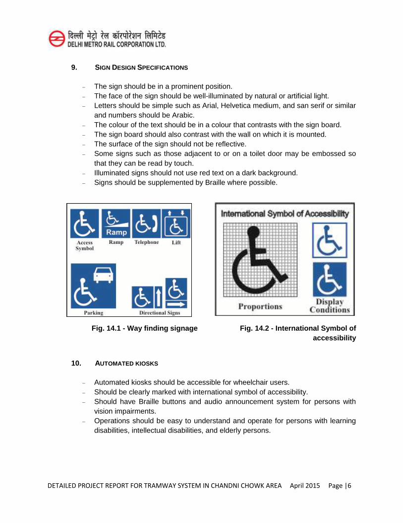
DETAILED PROJECT REPORT FOR TRAMWAY SYSTEM IN CHANDNI CHOWK AREA April 2015 Page |6
9. SIGN DESIGN SPECIFICATIONS
The sign should be in a prominent position. The face of the sign should be well-illuminated by natural or artificial light. Letters should be simple such as Arial, Helvetica medium, and san serif or similar
and numbers should be Arabic. The colour of the text should be in a colour that contrasts with the sign board. The sign board should also contrast with the wall on which it is mounted. The surface of the sign should not be reflective. Some signs such as those adjacent to or on a toilet door may be embossed so
that they can be read by touch. Illuminated signs should not use red text on a dark background. Signs should be supplemented by Braille where possible.
Fig. 14.1 - Way finding signage Fig. 14.2 - International Symbol of
accessibility
10. AUTOMATED KIOSKS
Automated kiosks should be accessible for wheelchair users. Should be clearly marked with international symbol of accessibility. Should have Braille buttons and audio announcement system for persons with
vision impairments. Operations should be easy to understand and operate for persons with learning
disabilities, intellectual disabilities, and elderly persons.
DETAILED PROJECT REPORT FOR TRAMWAY SYSTEM IN CHANDNI CHOWK AREA April 2015 Page |7
11. PUBLIC DEALING COUNTERS
Ticketing, Information, Check-in, Help desk, Restaurants, Shops, etc. should have public dealing counters.
Information or help desks should be close to the terminal entrance, and highly visible upon entering the terminal. In addition, they should be clearly identified and accessible to both those who use wheelchairs and those who stand.
It should provide information in accessible formats, viz. Braille leaflets for persons with vision impairments.
Ideally, these desks should have a map of the facility that desk attendants can view with passengers, when providing directions.
Staff manning the counters should know sign language. Information desk acoustics should be carefully planned and controlled as a high
level of background noise is confusing and disorienting to persons with hearing impairment.
Lighting should be positioned to illuminate the receptionist/person manning the counter and the desk top without creating glare.
Lighting should not create shadows over the receptionist staff, obscuring facial detail and making lip reading difficult.
There should be a hearing enhancement system such as a loop induction unit, the availability of which is clearly indicated with a symbol.
One of the counters should not be more than 800mm from the floor, with a minimum clear knee space of 650mm high and 280mm- 300mm deep .
12. AUDIO-VISUAL DISPLAYS
Terminal maps should be placed so that they are readily visible to persons who are standing and persons who use wheelchairs. They should also be accessible to persons with a visual disability (i.e. tactile maps). Other alternatives include electronic navigation systems or audio maps.
Enable captioning at all times on all televisions and other audiovisual displays that are capable of displaying captions and that are located in any portion of the terminal.
The captioning must be in high contrast for all information concerning travel safety, ticketing, check-in, delays or cancellations, schedule changes, boarding information, connections, checking baggage, individuals being paged by bus railway or airlines, vehicle changes that affect the travel of persons with disabilities, and emergencies (e.g., fire, bomb threat).
DETAILED PROJECT REPORT FOR TRAMWAY SYSTEM IN CHANDNI CHOWK AREA April 2015 Page |8
13. REST AREAS/SEATING
Seating area / benches should be provided along the circulation path at regular intervals so that passengers do not need to walk more than 50 to 60 metres before being able to sit and rest.
Where seating is provided, designated seating for passengers with disabilities is to be provided at boarding gates and departure areas within viewing distance of communication boards and/or personnel and identified by the symbol of access.
Public transit operators should provide seating in passenger service areas where there may be long waiting lines or times, including at ticket sales counters, check-in counters, secured screening and during inter-country travel in customs areas and baggage retrieval areas.
Designated seating should be provided for at boarding gates and departure areas within viewing distance of communication boards, and within hearing range of audio announcements as well. Such seating areas should be identified by the symbol of accessibility and shelter should be provided where this seating is outdoors.
In outdoor settings, seating should be provided along with the planned hawker spaces.
At waiting lounges for persons with disabilities chairs should have armrests and backrest.
14. TACTILE PAVING- GUIDING & WARNING1
(a) Tactile Guiding Paver (Line-Type)
It is recommended to install a row of tactile guidance paver along the entire length of the proposed accessible route for visual impaired persons. Care must be taken to ensure that there are no obstacles, such as wall, pillar, uneven surfaces, Soffit (underside /open area under the stairs, along the route traversed by the guidance paver. Also, there should be clear headroom of at least 2.1 meters height above the tactile guidance paver, free of protruding objects such as overhanging advertisement panel and signage, along the entire length of the walk.
(b) Tactile Warning Paver (Dot-Type)
Indicate an approaching potential hazard or a change in direction of the walkway, and serve as a warning of the approaching danger to persons with visual impairments, preparing them to tread cautiously and expect obstacles along the travel path, traffic intersections, doorways, stairs, etc. They are used to screen off obstacles, drop-offs or other hazards, to discourage movement in an incorrect
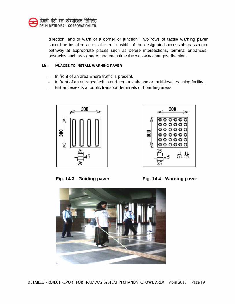
DETAILED PROJECT REPORT FOR TRAMWAY SYSTEM IN CHANDNI CHOWK AREA April 2015 Page |9
direction, and to warn of a corner or junction. Two rows of tactile warning paver should be installed across the entire width of the designated accessible passenger pathway at appropriate places such as before intersections, terminal entrances, obstacles such as signage, and each time the walkway changes direction.
15. PLACES TO INSTALL WARNING PAVER
In front of an area where traffic is present. In front of an entrance/exit to and from a staircase or multi-level crossing facility. Entrances/exits at public transport terminals or boarding areas.
Fig. 14.3 - Guiding paver Fig. 14.4 - Warning paver
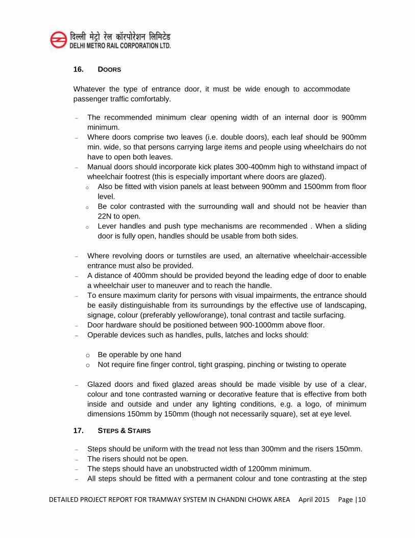
DETAILED PROJECT REPORT FOR TRAMWAY SYSTEM IN CHANDNI CHOWK AREA April 2015 Page |10
16. DOORS
Whatever the type of entrance door, it must be wide enough to accommodate passenger traffic comfortably.
The recommended minimum clear opening width of an internal door is 900mm
minimum. Where doors comprise two leaves (i.e. double doors), each leaf should be 900mm
min. wide, so that persons carrying large items and people using wheelchairs do not have to open both leaves.
Manual doors should incorporate kick plates 300-400mm high to withstand impact of wheelchair footrest (this is especially important where doors are glazed). o Also be fitted with vision panels at least between 900mm and 1500mm from floor
level. o Be color contrasted with the surrounding wall and should not be heavier than
22N to open. o Lever handles and push type mechanisms are recommended . When a sliding
door is fully open, handles should be usable from both sides.
Where revolving doors or turnstiles are used, an alternative wheelchair-accessible entrance must also be provided.
A distance of 400mm should be provided beyond the leading edge of door to enable a wheelchair user to maneuver and to reach the handle.
To ensure maximum clarity for persons with visual impairments, the entrance should be easily distinguishable from its surroundings by the effective use of landscaping, signage, colour (preferably yellow/orange), tonal contrast and tactile surfacing.
Door hardware should be positioned between 900-1000mm above floor. Operable devices such as handles, pulls, latches and locks should:
o Be operable by one hand o Not require fine finger control, tight grasping, pinching or twisting to operate
Glazed doors and fixed glazed areas should be made visible by use of a clear,
colour and tone contrasted warning or decorative feature that is effective from both inside and outside and under any lighting conditions, e.g. a logo, of minimum dimensions 150mm by 150mm (though not necessarily square), set at eye level.
17. STEPS & STAIRS
Steps should be uniform with the tread not less than 300mm and the risers 150mm. The risers should not be open. The steps should have an unobstructed width of 1200mm minimum. All steps should be fitted with a permanent colour and tone contrasting at the step
DETAILED PROJECT REPORT FOR TRAMWAY SYSTEM IN CHANDNI CHOWK AREA April 2015 Page |11
edge, extending the full width of the step, reaching a minimum depth of 50mm on both tread and riser.
Have continuous handrails on both sides including the wall (if any) at two levels Warning paver to be placed 300mm at the beginning and at the end of all stairs. Nosing to be avoided. The staircase should be adequately and uniformly illuminated during day and night
(when in use). The level of illumination should preferably fall between 100-150 lux. The rise of a flight between landings must be no more than 1200mm. There should be no more than 12 risers in one flight run. The stair covering and nosing should be slip-resistant, non-reflective, firmly-fixed
and easy to maintain. Soffit (underside /open area under the stairs) of the stairs should be enclosed or
protected.
18. HANDRAILS
Handrails should be circular in section with a diameter of 38-45mm and formed from materials which provide good grip such as timber, nylon or powder coating, matt finish metal finishes.
The handrail should contrast in colour (preferably yellow/orange) with surrounding surfaces.
At least 50mm clear of the surface to which they are attached and should be supported on brackets which do not obstruct continuous hand contact with the handrail.
The handrail should be positioned at two levels- 760mm and 900mm above the pitch-line of a flight of stairs.
Handrail at foot of the flight of stairs should extend 300mm beyond the stairs in the line of travel and returning to the wall or floor or rounded off, with a positive end that does not project into the route of travel.
19. RAMPS Ramps gradient should ideally be 1 in 20 and no greater than 1 in 12. Width of the ramp should not be less than 1200mm and preferred width is 1800mm. The steeper the gradient, the shorter the length of ramp between landings. On long ramps, a horizontal resting space should be provided every 6 meters. Surface materials should be slip-resistant, non-reflective, firmly-fixed and easily
maintained The edge of the ramp should have an edge protection with a minimum height of
100mm. Landings every 750mm of vertical rise. A tapping or lower rail should be positioned so that its bottom edge is no higher than
200mm above ground level.
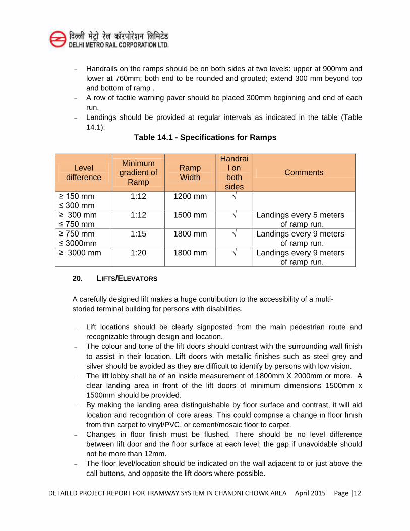
DETAILED PROJECT REPORT FOR TRAMWAY SYSTEM IN CHANDNI CHOWK AREA April 2015 Page |12
Handrails on the ramps should be on both sides at two levels: upper at 900mm and lower at 760mm; both end to be rounded and grouted; extend 300 mm beyond top and bottom of ramp .
A row of tactile warning paver should be placed 300mm beginning and end of each run.
Landings should be provided at regular intervals as indicated in the table (Table 14.1).
Table 14.1 - Specifications for Ramps
Level difference
Minimum gradient of
Ramp
Ramp Width
Handrail on both sides
Comments
≥ 150 mm ≤ 300 mm
1:12 1200 mm √
≥ 300 mm ≤ 750 mm
1:12 1500 mm √ Landings every 5 meters of ramp run.
≥ 750 mm ≤ 3000mm
1:15 1800 mm √ Landings every 9 meters of ramp run.
≥ 3000 mm
1:20 1800 mm √ Landings every 9 meters of ramp run.
20. LIFTS/ELEVATORS
A carefully designed lift makes a huge contribution to the accessibility of a multi-storied terminal building for persons with disabilities.
Lift locations should be clearly signposted from the main pedestrian route and
recognizable through design and location. The colour and tone of the lift doors should contrast with the surrounding wall finish
to assist in their location. Lift doors with metallic finishes such as steel grey and silver should be avoided as they are difficult to identify by persons with low vision.
The lift lobby shall be of an inside measurement of 1800mm X 2000mm or more. A clear landing area in front of the lift doors of minimum dimensions 1500mm x 1500mm should be provided.
By making the landing area distinguishable by floor surface and contrast, it will aid location and recognition of core areas. This could comprise a change in floor finish from thin carpet to vinyl/PVC, or cement/mosaic floor to carpet.
Changes in floor finish must be flushed. There should be no level difference between lift door and the floor surface at each level; the gap if unavoidable should not be more than 12mm.
The floor level/location should be indicated on the wall adjacent to or just above the call buttons, and opposite the lift doors where possible.
DETAILED PROJECT REPORT FOR TRAMWAY SYSTEM IN CHANDNI CHOWK AREA April 2015 Page |13
21. Lift Dimensions Provisions of at least one lift shall be made for people using wheelchairs with the
following car dimensions: o Clear internal depth -1500 mm minimum o Clear internal width - 1500 mm minimum o Entrance door width - 900 mm minimum
22. LIFT CONTROLS
The lift call button should be wall-mounted adjacent to the lift and should contrast with wall finish, either by using a contrasting panel, or a contrasting border around the button panel.
The call buttons should be located within the range 800-1000mm above floor finish. Buttons should not be touch sensitive, but should require a light positive pressure
and should ideally be large enough to be operable by the palm of the hand if required.
The control buttons inside the lift should be positioned on the side wall rather than front wall to allow access from the back and front of the lift car, by mobility aid users like wheelchair users.
The control buttons should contrast with their surroundings and illuminate when pressed and should incorporate highly visible tactile embossed (NOT engraved) characters and in Braille.
Time of closing of an automatic door should be more than 5 seconds and the closing speed should not exceed 25 meters per second. There should be a provision of censor enabled closing.
In larger lifts, controls should be positioned on both side walls, at least 400mm from front wall and between 800-1000mm above floor level.
23. CAR DESIGN
Internal walls should have a non-reflective, matt finish in a colour and tone contrasting with the floor, which should also have a matt, non-slip finish.
Use of reflective materials such as metal (stainless steel for example) can be problematic in creating sufficient contrast with control buttons, emergency telephone cabinet, etc. for persons with low vision and the use of such materials should be avoided wherever possible.
A mirror (750mm above floor level) on the rear wall can be useful to persons using wheelchairs and other mobility aids should they need to reverse safely out of the lift car or view the floor numbers.
Internal lighting should provide a level of illumination of minimum 100 lux (approximately 50-75 lux at floor level), uniformly distributed, avoiding the use of spotlights or down lighters.
DETAILED PROJECT REPORT FOR TRAMWAY SYSTEM IN CHANDNI CHOWK AREA April 2015 Page |14
A grab bar should be provided along both sides and the back wall, 900mm above floor level.
Handrails should be of tubular or oval cross section, in order to be easily gripped and capable of providing support.
Handrails should be positioned so that there is a clear space behind the handrail to allow it to be grasped i.e. knuckle space should be 50mm.
14.6 INFORMATION SYSTEMS Lifts should have both visual and audible floor level indicators Audible systems are also usually capable of incorporating additional messages,
such as door closing, or, in the case of an emergency, reassurance (with manual over-ride allowing communication with lift occupants).
Announcement system should be of 50 decibel. The display could be digital or segmented LED, or an appropriate alternative. A
yellow or light green on black display is preferred to a red on black display as it is easier to read.
14.7 GENERAL AND ACCESSIBLE TOILETS
1. SIGNAGES
All signage of general toilets should be in bold and contrasting colors. For persons with low vision and vision impairments: male pictogram in triangle and
female pictogram in circle, marked on plates along with Braille & raised alphabets, to be mounted on wall next to door near the latch side, at a height between 1400mm-1600mm.
Warning strip/ thin rubber door mat to be provided 300mm before and after the toilet entrance.
Tactile paver to be provided for urinals, WC and washbasins for persons with vision impairments.
2. ACCESSIBLE TOILETS
Should have the international symbol of accessibility displayed outside for wheelchair access.
The toilet door should be an outward opening door or two way opening or a sliding type and should provide a clear opening width of at least 900mm.
It should have a horizontal pull-bar, at least 600mm long, on the inside of the door, located so that it is 130mm from the hinged side of the door and at a height of 1000mm.
DETAILED PROJECT REPORT FOR TRAMWAY SYSTEM IN CHANDNI CHOWK AREA April 2015 Page |15
3. WC COMPARTMENT DIMENSIONS
The dimensions of a unisex toilet are critical in ensuring access. The compartment should be at least 2200mm and 2000mm. This will allow use by both manual and motorized wheelchair users.
Layout of the fixtures in the toilet should be such that a clearing maneuvering space of 1500mm x 1500mm in front of the WC and washbasin.
4. WATER CLOSET (WC) FITTINGS
Top of the WC seat should be 450-480mm above finished floor level, preferably be of wall hung or corbel type as it provides additional space at the toe level.
An unobstructed space 900mm wide should be provided to one side of the WC for transfer, together with a clear space 1200mm deep in front of the WC.
WC should be centred 500mm away from the side wall, with the front edge of the pan 750mm away from the back wall. Have a back support. The WC with a back support should not incorporate a lid, since this can hinder transfer.
L-shape grab bar at the adjacent wall and on the transfer side (open side) swing up grab bar shall be provided.
The cistern should have a lever flush mechanism, located on the transfer side and not on the wall side and not more than 1000mm from the floor.
5. GRAB BARS
Grab bars should be manufactured from a material which contrasts with the wall finish (or use dark tiles behind light colored rails), be warm to touch and provide good grip.
It is essential that all grab rails are adequately fixed, since considerable pressure will be placed on the rail during maneuvering. Grab bars should sustain weight of 200kgs minimum.
A hinged type moveable grab bar should be installed adjacent to the WC on the transfer side. This rail can incorporate a toilet tissue holder. A distance of 320mm from the centre line of the WC between heights of 200-250mm from the top of the WC seat. It should extend 100-150mm beyond the front of the WC.
A fixed wall-mounted L- shape grab bar (600mm long horizontal and 700mm long vertical) on the wall side should be provided. It should be placed at a height of 200-250mm above the WC seat level.
6. WASHBASINS Hand washbasins should be fitted on cantilevered brackets fixed to the wall. The basin should be fixed no higher than 750mm above the finished floor level. Be of dimensions 520mm and 410mm, mounted such that the top edge is between
800- 900mm from the floor; have a knee space of at least 760mm wide by 200mm
DETAILED PROJECT REPORT FOR TRAMWAY SYSTEM IN CHANDNI CHOWK AREA April 2015 Page |16
deep by 650-680mm high. The position of the basin should not restrict access to the WC i.e. it should be
located 900mm away from the WC. A lever operated mixer tap fitted on the side of the basin closest to the WC is useful
as it allows hot and cold water to be used from a seated position on the WC. The hand drying facilities should be located close to the hand washbasin between
1000-1200mm. Lever type handles for taps are recommended. Mirror’s bottom edge to be 1000mm from the floor and may be inclined at an angle.
7. FIXTURES AND FITTINGS Contrast between fittings and fixtures and wall or floor finishes will assist in their
location. For example, using contrasting fittings, or dark tiles behind white hand washbasins and urinals, contrasting soap dispensers and toilet roll holders. Contrast between critical surfaces, e.g. floors, walls and ceilings helps to define the dimensions of the room.
Towel rails, rings and handrails should be securely fixed to the walls and positioned at 800-1000mm from the floor.
The mirror should be tilted at an angle of 300 for better visibility by wheelchair users. It should have lower edge at 1000mm above floor finish and top edge around
1800mm above floor finish. Hooks should be available at both lower-1200mm and standard heights- 1400mm,
projecting not more than 40mm from the wall. Where possible, be equipped with a shelf of dimensions 400mm x 200mm fixed at a
height of between 900mm and 1000mm from the floor. Light fittings should illuminate the user's face without being visible in the mirror. For
this reason, most units which have an integral light are unsatisfactory. Large, easy to operate switches are recommended, contrasting with background to
assist location, at a maximum height of 1000mm above floor finish. All toilet facilities should incorporate visual fire alarms. Alarms must be located so that assistance can be summoned both when on the
toilet pan i.e. at 900mm height and lying on the floor i.e. at 300mm, from floor surface. Alarms should be located close to the side wall nearest the toilet pan, 750mm away from rear wall and at 900mm and 200mm above floor finish
8. SIGNAGE OF ACCESSIBLE TOILETS All unisex accessible toilets to have access symbol in contrast colours. A distinct
audio sound (beeper/clapper) may be installed above the entrance door for identification of the toilets.
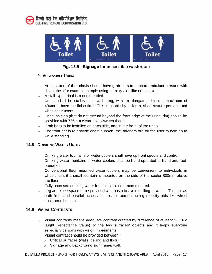
DETAILED PROJECT REPORT FOR TRAMWAY SYSTEM IN CHANDNI CHOWK AREA April 2015 Page |17
Fig. 13.5 - Signage for accessible washroom
9. ACCESSIBLE URINAL
At least one of the urinals should have grab bars to support ambulant persons with disabilities (for example, people using mobility aids like crutches).
A stall-type urinal is recommended. Urinals shall be stall-type or wall-hung, with an elongated rim at a maximum of
430mm above the finish floor. This is usable by children, short stature persons and wheelchair users.
Urinal shields (that do not extend beyond the front edge of the urinal rim) should be provided with 735mm clearance between them.
Grab bars to be installed on each side, and in the front, of the urinal. The front bar is to provide chest support; the sidebars are for the user to hold on to
while standing.
14.8 DRINKING WATER UNITS
Drinking water fountains or water coolers shall have up front spouts and control. Drinking water fountains or water coolers shall be hand-operated or hand and foot-
operated. Conventional floor mounted water coolers may be convenient to individuals in
wheelchairs if a small fountain is mounted on the side of the cooler 800mm above the floor.
Fully recessed drinking water fountains are not recommended. Leg and knee space to be provided with basin to avoid spilling of water . This allows
both front and parallel access to taps for persons using mobility aids like wheel chair, crutches etc.
14.9 VISUAL CONTRASTS
Visual contrasts means adequate contrast created by difference of at least 30 LRV (Light Reflectance Value) of the two surfaces/ objects and it helps everyone especially persons with vision impairments.
Visual contrast should be provided between: o Critical Surfaces (walls, ceiling and floor), o Signage and background sign frame/ wall,
DETAILED PROJECT REPORT FOR TRAMWAY SYSTEM IN CHANDNI CHOWK AREA April 2015 Page |18
o Step edges and risers/ treads on steps, o Handrails and background walls, o Doors and surrounding walls, o Switches/ sockets and background wall, o Toilet fixtures and critical surfaces in toilet.
Barriers and hazards should be highlighted by incorporating colours and luminance
contrast.
14.10 EMERGENCY EGRESS/EVACUATION Placement (accessibility) and visibility of such devices is very important. The
following is to be considered for the installation of such alarm devices; fire alarm boxes, emergency call buttons and lit panels should be installed between heights of 800mm and 1000mm from the furnished floor surface. These should be adequately contrasted from the background wall and should be labelled with raised letters and should also be in Braille.
A pre-recorded message, alerting an emergency to the control room or reception
should be installed in the telephone and this should be accessible by a ‘hotkey’ on
the phone keypad. This ‘hotkey’ should be distinct from the rest of the keypad.
14.11 ALERTING SYSTEMS
In emergency situations, it is critical that people are quickly alerted to the situation at hand, for persons with disability the following needs to be considered.
Consider having audible alarms with ‘voice instructions’ that can help guide them to
the nearest emergency exit. As an alternative to the pre-recorded messages, these alarms may be connected to the central control room for on-the-spot broadcasts.
Non-auditory alarms (visual or sensory) to alert persons with hearing impairments
should be installed at visible locations in all areas that the passengers may use (including toilet areas, etc).
Non-auditory alarms include: Flashing beacons Vibrating pillows and vibrating beds. Pagers or mobile phones that give out a vibrating alarm along with a flashing light
(these may be issued to persons with vision or hearing impairments at the time of check-in or boarding the vehicle.)
DETAILED PROJECT REPORT FOR TRAMWAY SYSTEM IN CHANDNI CHOWK AREA April 2015 Page |19
14.12 WRITTEN EVACUATION PROCEDURE
A written evacuation procedure that details the egress plan for people with disability should be installed behind the entrance door in the accessible rest rooms. The evacuation procedure should be detailed in large print letters that contrast strongly against the background. Where possible, it should also incorporate raised letters and Braille. The evacuation route should be displayed on a high contrast tactile map for benefit of persons with vision impairments.
14.13 EMERGENCY EVACUATION ROUTE
Designate routes that are at least 1200mm wide, to ensure that a person using a wheelchair and a non disabled person are able to pass each other along the route. The route should be free of any steps or sudden changes in level and should be kept free from obstacles such as furniture, coolers, AC units and flower pots.
Use Exit signage along the route. Orientation and direction signs should be installed frequently along the evacuation route and these should preferably be internally illuminated. The exit door signage should also be internally illuminated.
A ‘way guidance lighting system’ consisting of low mounted LED strips to outline the
exit route (with frequent illuminated direction indicators along the route) should be installed along the entire length of the evacuation route. Way guidance systems allow persons with vision impairments to walk significantly faster than traditional overhead emergency lighting. Moreover, emergency exit lights in green color and directional signals mounted near the floor have been found to be useful for all people in cases where a lot of smoke is present.
14.14 WAY GUIDANCE SYSTEM
Luminance on the floor should be 1lux minimum provided on along the centre line of the route and on stairs.
Install clear illuminated sign above exit and also directional signage along the route. The directional exit signs with arrows indicating the way to the escape route should
be provided at a height of 500mm from the floor level on the wall and should be internally illuminated by electric light connected to corridor circuits.
14.15 FIRE RESISTANT DOORS Fire resistant doors and doors used along the emergency evacuation route are
generally heavy and the force required to open these is much higher than 25 Newtons, making it difficult for people with disability to negotiate these doors independently. There are, however, magnetic and other types of door holders
DETAILED PROJECT REPORT FOR TRAMWAY SYSTEM IN CHANDNI CHOWK AREA April 2015 Page |20
available that can be connected to fire alarms so that they will hold the doors open normally but will release the doors when the fire alarm is activated.
14.16 STREET DESIGN
(a) Footpath (Sidewalk)
Footpaths should be regarded as a transportation system which is connected and continuous, just like roadways and railways. They should not be sporadically placed where ever convenient, but instead should be provided consistently between all major attractions, trip generators, and other locations where people walk.
Footpath should: Be along the entire length of the road; Have height of a standard public step riser i.e. 150 mm maximum; Be at least 1800 mm wide; Have non-slip surface; Have tactile guiding paver for persons with visual impairments; Preferably have well defined edges of paths and routes by use of different colours
and textures; Have no obstacles or projections along the pathway. If this is unavoidable, there
should be clear headroom of at least 2200 mm from the floor level; The minimum 1.8m (width) x 2.2m (Height) Walking Zone should be clear of all
obstructions – both horizontally and vertically.
Footpath should have:
Have kerb ramps where ever a person is expected to walk into or off the pathway; and
Have tactile warning paver installed next to all entry and exit points from the footpath.
(b) Kerb Ramp
Kerb should be dropped, to be flush with walk way, at a gradient no greater than 1:10 on both sides of necessary and convenient crossing points. Width should not be less than 1200mm. If width (X) is less than 1200mm, then slope of the flared side shall not exceed 1:12.
Floor tactile paving- Guiding & Warning paver shall be provided to guide persons with vision impairment so that a person with vision impairment does not accidentally walk onto the road.
Finishes shall have non-slip surface with a texture traversable by a wheel chair.
DETAILED PROJECT REPORT FOR TRAMWAY SYSTEM IN CHANDNI CHOWK AREA April 2015 Page |21
(c) Road Intersections
Pedestrian crossings should be equipped with traffic control signal. Traffic islands to reduce the length of the crossing are recommended for the safety
of all road users. Warning pavers should be provided to indicate the position of pedestrian crossings
for the benefit of people with visual impairments. Table tops (raised road level to the sidewalk height) are helpful in reducing the
speed of traffic approaching the intersection
(d) Median/Pedestrian Refuge
Raised islands in crossings should: Cut through and level with the street; or Have kerb ramps on both the sides and have a level area of not less than 1500 mm
long in the middle; and A coloured tactile marking strip at least 600 mm wide should mark the beginning and
end of a median/ pedestrian refuge to guide pedestrian with visual impairments to its location.
14.17 TRAFFIC SIGNALS Pedestrian traffic lights should be provided with clearly audible signals for the benefit
of pedestrians with visual impairments; Acoustic devices should be installed on a pole at the point of origin of crossing and
not at the point of destination; The installation of two adjacent acoustic devices such as beepers is not
recommended in order to avoid disorientation; The time interval allowed for crossing should be programmed according to the
slowest crossing persons; and Acoustical signals encourage safer crossing behaviour among children as well.
14.18 SUBWAY AND FOOT OVER BRIDGE
Subways and foot over bridges should be accessible for people with disabilities. This may be achieved by: Provision of signage at strategic location; Provision of slope ramps or lifts at both the ends to enable wheelchair accessibility ; Ensuring that the walkway is at least 1500 mm wide; Provision of tactile guiding and warning paver along the length of the walkway; Keeping the walkway; free from any obstructions and projections; and Providing for seats for people with ambulatory disabilities at regular intervals along
the walkway and at landings.
DETAILED PROJECT REPORT FOR TRAMWAY SYSTEM IN CHANDNI CHOWK AREA April 2015 Page |22
14.19 ALIGHTING AND BOARDING AREAS
All areas and services provided in the Mass Rapid Transit System (Metro/subway), bus terminuses, etc. that are open to the public should be accessible.
14.20 APPROACH
Passenger walkways, including crossings to the bus stops, taxi stands, terminal / station building, etc. should be accessible to persons with disabilities.
Uneven surfaces should be repaired and anything that encroaches on corridors or paths of travel should be removed to avoid creating new barriers. Any obstructions or areas requiring maintenance should be white cane detectable2.
Access path from plot entry and surface parking to terminal entrance shall have even surface without any steps.
Slope, if any, shall not have gradient greater than 5%. The walkway should not have a gradient exceeding 1:20. It also refers to cross slope.
Texture change in walk ways adjacent to seating by means of tactile warning paver should be provided for persons with vision impairment.
Avoid gratings in walks.
14.21 CAR PARK
(A) SIGNAGE International symbol of accessibility (wheelchair sign) should be displayed at
approaches and entrances to car parks to indicate the provision of accessible parking lot for persons with disabilities within the vicinity.
Directional signs shall be displayed at points where there is a change of direction to direct persons with disabilities to the accessible parking lot.
Where the location of the accessible parking lot is not obvious or is distant from the approach viewpoints, the directional signs shall be placed along the route leading to the accessible parking lot.
Accessible parking lot should be identifiable by the International Symbol of Accessibility. The signs should not be obscured by a vehicle parked in the designated lot.
Vertical signs shall be provided, to make it easily visible, the sign should be at a minimum height of 2100 mm .
DETAILED PROJECT REPORT FOR TRAMWAY SYSTEM IN CHANDNI CHOWK AREA April 2015 Page |23
(B) SYMBOL International Symbol of Accessibility should be clearly marked on the accessible parking
lot for drivers/riders with disabilities only. A square with dimensions of at least 1000 mm but not exceeding 1500 mm in
length; Be located at the centre of the lot; and The colour of the symbol should be white on a blue background.
(C) CAR PARK ENTRANCE The car park entrance should have a height clearance of at least 2400 mm.
LOCATION Accessible parking lots that serve a building should be located nearest to an
accessible entrance and / or lift lobby within 30 meters. In case the access is through lift, the parking shall be located within 30 meters.
The accessible route of 1200 mm width is required for wheelchair users to pass behind vehicle that may be backing out.
(D) ACCESSIBLE CAR PARKING LOT The accessible car parking lot should: Have minimum dimensions 5000 mm × 3600 mm; Have a firm, level surface without aeration slabs; Wherever possible, be sheltered; Where there are two accessible parking bays adjoining each other, then the 1200
mm side transfer bay may be shared by the two parking bays. The transfer zones, both on the side and the rear should have yellow and while cross-hatch road markings;
Two accessible parking lots shall be provided for every 25 no of car spaces. (E) DROP OFF AND PICK UP AREAS Designated drop-off and pick-up spaces, to be clearly marked with international
symbol of accessibility. Kerbs wherever provided, should have kerb ramps.
DETAILED PROJECT REPORT FOR TRAMWAY SYSTEM IN CHANDNI CHOWK AREA April 2015 Page |1
CHAPTER -15
SECURITY MEASURES FOR A TRAM SYSTEM
15.1 INTRODUCTION
Tram is emerging as the most favoured mode of urban transportation system in the world. The inherent characteristics of tramway system make it an ideal target for terrorists and miscreants. Tramway systems are typically open and dynamic systems which carry thousands of commuters. Moreover the high cost of infrastructure, its economic importance, being the life line of city high news value, fear & panic and man casual ties poses greater threat to its security. Security is a relatively new challenge in the context of public transport. It addresses problems caused intentionally. Security differs from safety which addresses problems caused accidentally. Security problems or threats are caused by people whose actions aim to undermine or disturb the public transport system and/or to harm passengers or staff. These threats range from daily operational security problems such as disorder, vandalism and assault to the terrorist threat.
15.2 NECESSSITY OF SECURITY
It is well known that public transportation is increasingly important for urban areas to prosper in the face of challenges such as reducing congestion and pollution. Therefore, security places an important role in helping public transport system to become the mode of choice. Therefore, excellence in security is a prerequisite for Tramway system for increasing its market share. Tramway system administration must ensure that security model must keep pace rapid expansion of the metro and changing security scenario.
15.3 THREE PILLARS OF SECURITY
Security means protection of physical. Human and intellectual assets either from criminal interference, removal or destruction by terrorists or criminals or incidental to technological failures or natural hazardous events. There are three important pillars of security as mentioned under:
(i) The human factor;
(ii) Procedures; and
(iii) Technology
Staff engaging with the passengers create a sense of re-assurance which cannot fully be achieved by technology. For human factor to be more effective staff has to be qualified, trained, well equipped and motivated. They should be trained, drilled and
DETAILED PROJECT REPORT FOR TRAMWAY SYSTEM IN CHANDNI CHOWK AREA April 2015 Page |2
tested. The security risk assessment is the first step for understanding the needs and prioritizing resources. The organization of security should be clear and consistent. Security incidents, especially major ones, often happen without warning. Emergency and contingency plans must be developed communicated and drilled in advance.
There are number of technologies which can be used to enhance security e.g. surveillance systems. The objectives of the security systems are to differ i.e., making planning or execution of on attack too difficult, detect the planned evidence before it occurs deny the access after in plan of attack has been made and to mitigate i.e. lessen the impact severity as the attack by appropriate digits.
15.4 PHASES OF SECURITY
There are three phases of security as under:
(i) Prevention
These are the measures which can prevent a security incidence from taking place. These can be identified by conducting a risk assessment and gathering intelligence. Prevention begins with the daily operational security -problems. Uncared for dirty, damaged property is a breeding ground for more serious crime.
(ii) Preparedness Plans must be prepared to respond to incidents, mitigate the impact. Tram staff
accordingly and carry out exercises. The results of the risk assessment give a basis for such plans.
(iii) Recovery Tram system must have laid down procedures/instructions for the quick recovery
of normal service after an incident. Recovery is important for the financial health of the operation, but it also sends a clear message to public, it reassures passengers and gives them confidence to continue using the system. Communication is key to the quick restoration after such incidents. Restoration should also include an evaluation process for the lessons learnt.
15.5 RESPONSIBILITIES AND PARTNERSHIPS
Security is a sovereign function and hence is the responsibility of the state. Security in public requires clear governance. Responsibility should be clearly defined. In the present scenario, this is the responsibility of the Central Government/MHA in Delhi to ensure secured travelling to the public including Tramway.
CISF can be entrusted with the job of providing security to Tramway and law & order/
prevention & detection of crime are under the domain of Delhi Police.
DETAILED PROJECT REPORT FOR TRAMWAY SYSTEM IN CHANDNI CHOWK AREA April 2015 Page |3
15.6 PROPOSED PROVISIONS FOR SECURITY SYSTEM
1. CCTV coverage of all tramway system. With a provision of monitoring in the Station Security Room as well as at a Centralized Security Control Room with video wall, computer with access to internet TV with data connection, printer and telephone connection (Land Line and EPBX) for proper functioning, cluster viewing for stop points. Cost of this is included in Telecom estimate.
2. Minimum one Baggage Scanners on all entry points (1 per AFC array).Cost of one baggage scanner is Rs. 15.0 Lacs approximately, on 2013 prices.
3. Multi-zone Door Frame Metal Detector (DFMD) minimum three per entry (2 per AFC array). The number can increase in view of the footfall at over crowed stations. Cost of one Multi-zone DFMD is Rs 2.15 Lacs approximately.
4. Hand held Metal Detector (HHMD) as per requirement of security agency, minimum two per entry, which varies from station to station with at least 1.5 per DFMD installed at the station. Cost of one HHMD is Rs 6000/- approximately at 2012 prices.
5. Bomb Detection Equipments with modified vehicle as per requirement of security agency. One BDS team per 25 - 30 stopage will be required at par with present criteria of DMRC. Cost 1.25 crores including vehicle.
6. Bomb Blanket at least one per stop point and Depots. Cost is Rs. 50,000/- per bomb blanket.
7. Wireless Sets (Static and Hand Held) as per requirement of security agency. 8. Dragon light at least one per station and vital installation. 9. Mobile phones, land lines and EPBX phone connections for senior security officers
and control room etc. 10. Dog Squads (Sniffer Dog), at least one dog for 4 Tram stopage which is at par with
current arrangement of Delhi Metro. Cost of one trained sniffer dog is Rs 1.25 Lacs approximately. Dog Kennels along with provision for dog handlers and MI room will also be provided by tram depot administration including land at suitable places line wise.
11. Bullet proof Morcha one per security check point (i.e. AFC array) and entry gate of Tram depot administration .
DETAILED PROJECT REPORT FOR TRAMWAY SYSTEM IN CHANDNI CHOWK AREA April 2015 Page |4
12. Bullet proof jackets and helmets for QRTs and riot control equipments including space at nominated stoppages. One QRT Team will look after 5-6 tram stoppages. One QRT consist of 5 personnel and perform duty in three shifts.
13. Furniture to security agency for each security room, and checking point at every entry point at stoppages. Scale is one office table with three chairs for security room and office of GO and one steel top table with two chairs for checking point.
14. Ladies frisking booth - 1 per security check point (AFC Arrey)
Wooden Ramp - 1 per DFMD for security check points.
15. Wall mounted/ pedestal fan at security check point, ladies frisking booth and bullet proof morcha, as per requirement.
15. Physical barriers for anti scaling at Ramp area, low height of via duct by providing iron grill of appropriate height & design/concertina wire.
17. Adequate number of ropes. Queue managers, cordoning tapes, dragon search lights for contingency.
18. Iron grill in the corridor staircases, proper segregation of paid and unpaid by providing appropriate design grills etc.
19. Proper design of emergency staircase and Fireman entry to prevent unauthorized entry.
DETAILED PROJECT REPORT FOR TRAMWAY SYSTEM IN CHANDNI CHOWK AREA April 2015 Page |1
CHAPTER-16
MULTI MODEL TRAFFIC INTEGRATION
16.1 INTRODUCTION
The proposed tramway system in Chandni Chowk area comprises of two systems, one at grade with APS system which will pass through partly on Netaji subhash Road, Chandni Chowk, Khari Baoli and partly on Naya bazaar road .and the second will be an elevated corridor with Over head Catanary System from Naya bazaar road stoppage to Netaji Subhash Road stoppage via S.P Mukherji marg. In all there are seven stoppages at grade and three stoppage elevated.
The Chandni Chowk area is very dense commercial area as presently have auto, cars, and two wheelers, cycle rickshaws as main transport to the Chandni Chowk, Fatehpuri Masjid, and Khari Baoli area. The Chandni Chowk area is surrounded by Naya bazaar road, S.P Mukherji marg and Netaji Subhash marg which already have a local bus service known as DTC bus service. The private transportations like cars, two wheelers etc. as such the existing transport system will continue to work as integral part of the proposed tramway system. Moreover the Delhi Metro Rail is already in existence at Delhi main junction known as Chandni Chowk Metro Station and one more station on Netaji Subhash marg near Bhagirath place (opposite lal Quila)is coming in near future will also work as integral part of the transport system of Chandni Chowk area.
As a high quality Tramway system is proposed, the operation of Tram will definitely decongest the Chandni Chowk road. To make the area pedestrian friendly the redevelopment plan of the Chandni Chowk area will be enforced and all footpaths etc will be remodeled as per the plan. The footpath etc near the platforms in the elevated corridor will also be integrated as per the requirement to give easy accessibility to tram riders /pedestrians and to give an aesthetic look to the area.
16.2 CHANDNI CHOWK AND ITS CONNECTIVITY TO CITY BUSES
16.2.1 General
The Chandni Chowk and its surrounding areas like Red fort and Delhi Junction Railway Station has a dense network of city buses which leads to major residential, commercial and industrial areas. In order to appreciate the bus connectivity to the Chandni Chowk area from the surrounding areas, an exercise has been carried out to chart the bus routes leading to some of the important interchange points with the Chandni Chowk area. This data has been processed and presented in following paras. This produces valuable information which leads to defining any need for augmentation of bus services
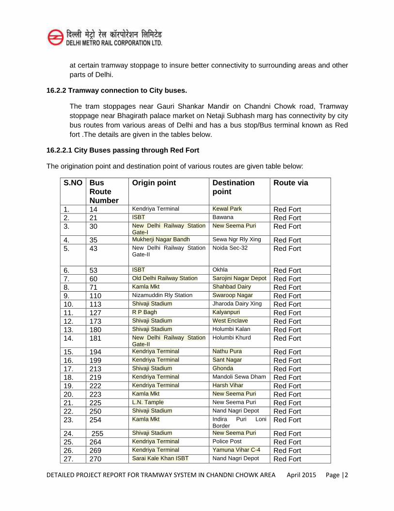
DETAILED PROJECT REPORT FOR TRAMWAY SYSTEM IN CHANDNI CHOWK AREA April 2015 Page |2
at certain tramway stoppage to insure better connectivity to surrounding areas and other parts of Delhi.
16.2.2 Tramway connection to City buses.
The tram stoppages near Gauri Shankar Mandir on Chandni Chowk road, Tramway stoppage near Bhagirath palace market on Netaji Subhash marg has connectivity by city bus routes from various areas of Delhi and has a bus stop/Bus terminal known as Red fort .The details are given in the tables below.
16.2.2.1 City Buses passing through Red Fort
The origination point and destination point of various routes are given table below:
S.NO Bus Route Number
Origin point Destination point
Route via
1. 14 Kendriya Terminal Kewal Park Red Fort 2. 21 ISBT Bawana Red Fort 3. 30 New Delhi Railway Station
Gate-I New Seema Puri Red Fort
4. 35 Mukherji Nagar Bandh Sewa Ngr Rly Xing Red Fort 5. 43 New Delhi Railway Station
Gate-II
Noida Sec-32 Red Fort
6. 53 ISBT Okhla Red Fort 7. 60 Old Delhi Railway Station Sarojini Nagar Depot Red Fort 8. 71 Kamla Mkt Shahbad Dairy Red Fort 9. 110 Nizamuddin Rly Station Swaroop Nagar Red Fort 10. 113 Shivaji Stadium Jharoda Dairy Xing Red Fort 11. 127 R P Bagh Kalyanpuri Red Fort 12. 173 Shivaji Stadium West Enclave Red Fort 13. 180 Shivaji Stadium Holumbi Kalan Red Fort 14. 181 New Delhi Railway Station
Gate-II Holumbi Khurd Red Fort
15. 194 Kendriya Terminal Nathu Pura Red Fort 16. 199 Kendriya Terminal Sant Nagar Red Fort 17. 213 Shivaji Stadium Ghonda Red Fort 18. 219 Kendriya Terminal Mandoli Sewa Dham Red Fort 19. 222 Kendriya Terminal Harsh Vihar Red Fort 20. 223 Kamla Mkt New Seema Puri Red Fort 21. 225 L.N. Tample New Seema Puri Red Fort 22. 250 Shivaji Stadium Nand Nagri Depot Red Fort 23. 254 Kamla Mkt Indira Puri Loni
Border Red Fort
24. 255 Shivaji Stadium New Seema Puri Red Fort 25. 264 Kendriya Terminal Police Post Red Fort 26. 269 Kendriya Terminal Yamuna Vihar C-4 Red Fort 27. 270 Sarai Kale Khan ISBT Nand Nagri Depot Red Fort
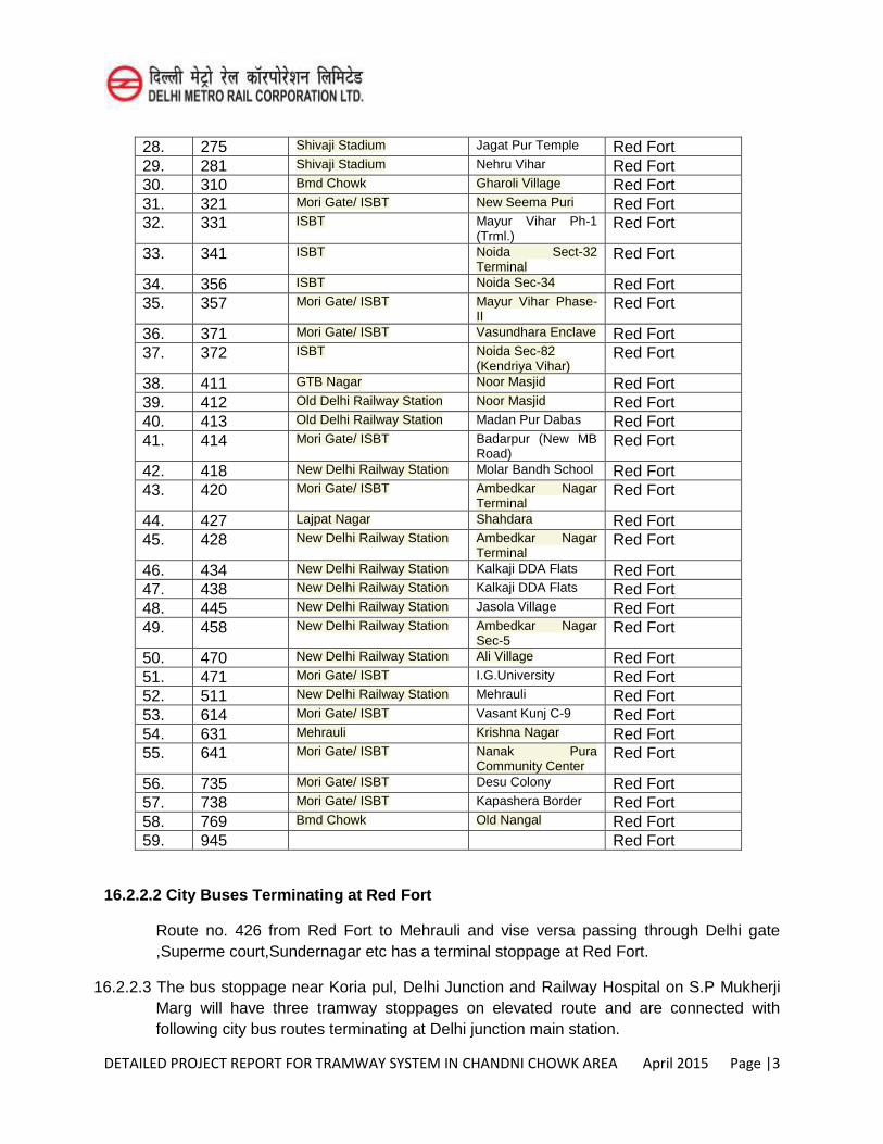
DETAILED PROJECT REPORT FOR TRAMWAY SYSTEM IN CHANDNI CHOWK AREA April 2015 Page |3
28. 275 Shivaji Stadium Jagat Pur Temple Red Fort 29. 281 Shivaji Stadium Nehru Vihar Red Fort 30. 310 Bmd Chowk Gharoli Village Red Fort 31. 321 Mori Gate/ ISBT New Seema Puri Red Fort 32. 331 ISBT Mayur Vihar Ph-1
(Trml.) Red Fort
33. 341 ISBT Noida Sect-32 Terminal
Red Fort
34. 356 ISBT Noida Sec-34 Red Fort 35. 357 Mori Gate/ ISBT Mayur Vihar Phase-
II Red Fort
36. 371 Mori Gate/ ISBT Vasundhara Enclave Red Fort 37. 372 ISBT Noida Sec-82
(Kendriya Vihar) Red Fort
38. 411 GTB Nagar Noor Masjid Red Fort 39. 412 Old Delhi Railway Station Noor Masjid Red Fort 40. 413 Old Delhi Railway Station Madan Pur Dabas Red Fort 41. 414 Mori Gate/ ISBT Badarpur (New MB
Road) Red Fort
42. 418 New Delhi Railway Station Molar Bandh School Red Fort 43. 420 Mori Gate/ ISBT Ambedkar Nagar
Terminal Red Fort
44. 427 Lajpat Nagar Shahdara Red Fort 45. 428 New Delhi Railway Station Ambedkar Nagar
Terminal Red Fort
46. 434 New Delhi Railway Station Kalkaji DDA Flats Red Fort 47. 438 New Delhi Railway Station Kalkaji DDA Flats Red Fort 48. 445 New Delhi Railway Station Jasola Village Red Fort 49. 458 New Delhi Railway Station Ambedkar Nagar
Sec-5 Red Fort
50. 470 New Delhi Railway Station Ali Village Red Fort 51. 471 Mori Gate/ ISBT I.G.University Red Fort 52. 511 New Delhi Railway Station Mehrauli Red Fort 53. 614 Mori Gate/ ISBT Vasant Kunj C-9 Red Fort 54. 631 Mehrauli Krishna Nagar Red Fort 55. 641 Mori Gate/ ISBT Nanak Pura
Community Center Red Fort
56. 735 Mori Gate/ ISBT Desu Colony Red Fort 57. 738 Mori Gate/ ISBT Kapashera Border Red Fort 58. 769 Bmd Chowk Old Nangal Red Fort 59. 945 Red Fort
16.2.2.2 City Buses Terminating at Red Fort
Route no. 426 from Red Fort to Mehrauli and vise versa passing through Delhi gate ,Superme court,Sundernagar etc has a terminal stoppage at Red Fort.
16.2.2.3 The bus stoppage near Koria pul, Delhi Junction and Railway Hospital on S.P Mukherji Marg will have three tramway stoppages on elevated route and are connected with following city bus routes terminating at Delhi junction main station.
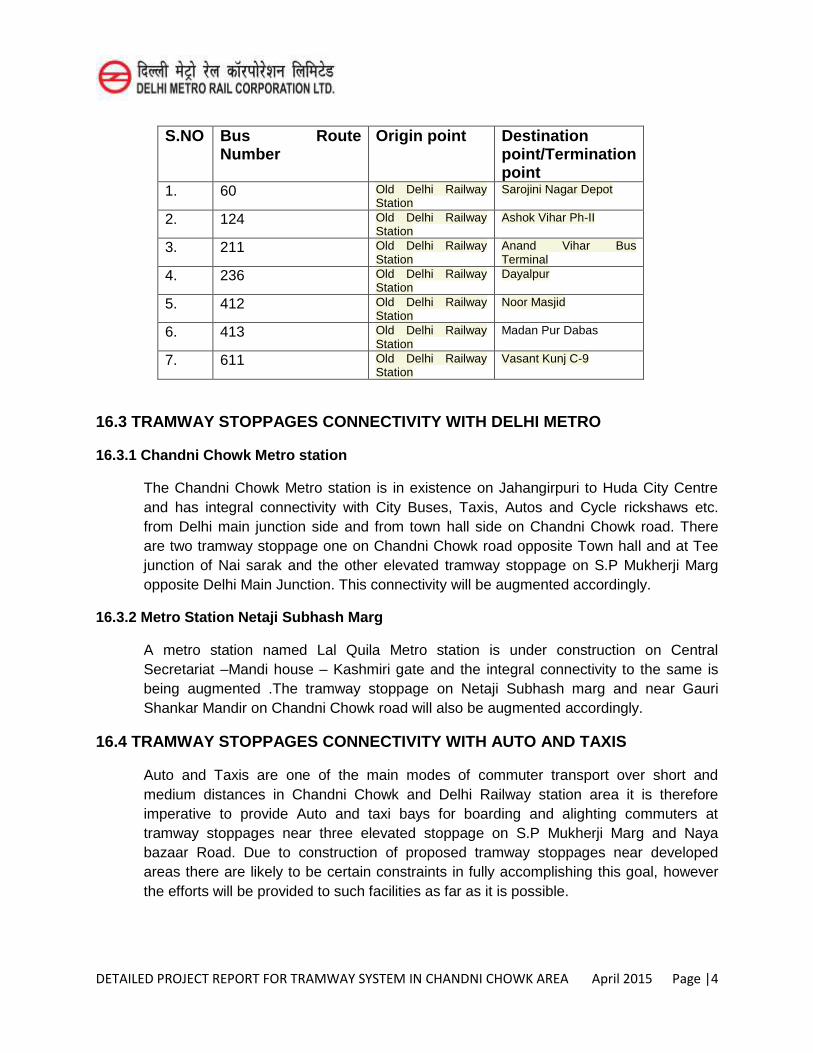
DETAILED PROJECT REPORT FOR TRAMWAY SYSTEM IN CHANDNI CHOWK AREA April 2015 Page |4
S.NO Bus Route Number
Origin point Destination point/Termination point
1. 60 Old Delhi Railway Station
Sarojini Nagar Depot
2. 124 Old Delhi Railway Station
Ashok Vihar Ph-II
3. 211 Old Delhi Railway Station
Anand Vihar Bus Terminal
4. 236 Old Delhi Railway Station
Dayalpur
5. 412 Old Delhi Railway Station
Noor Masjid
6. 413 Old Delhi Railway Station
Madan Pur Dabas
7. 611 Old Delhi Railway Station
Vasant Kunj C-9
16.3 TRAMWAY STOPPAGES CONNECTIVITY WITH DELHI METRO
16.3.1 Chandni Chowk Metro station
The Chandni Chowk Metro station is in existence on Jahangirpuri to Huda City Centre and has integral connectivity with City Buses, Taxis, Autos and Cycle rickshaws etc. from Delhi main junction side and from town hall side on Chandni Chowk road. There are two tramway stoppage one on Chandni Chowk road opposite Town hall and at Tee junction of Nai sarak and the other elevated tramway stoppage on S.P Mukherji Marg opposite Delhi Main Junction. This connectivity will be augmented accordingly.
16.3.2 Metro Station Netaji Subhash Marg
A metro station named Lal Quila Metro station is under construction on Central Secretariat –Mandi house – Kashmiri gate and the integral connectivity to the same is being augmented .The tramway stoppage on Netaji Subhash marg and near Gauri Shankar Mandir on Chandni Chowk road will also be augmented accordingly.
16.4 TRAMWAY STOPPAGES CONNECTIVITY WITH AUTO AND TAXIS
Auto and Taxis are one of the main modes of commuter transport over short and medium distances in Chandni Chowk and Delhi Railway station area it is therefore imperative to provide Auto and taxi bays for boarding and alighting commuters at tramway stoppages near three elevated stoppage on S.P Mukherji Marg and Naya bazaar Road. Due to construction of proposed tramway stoppages near developed areas there are likely to be certain constraints in fully accomplishing this goal, however the efforts will be provided to such facilities as far as it is possible.
DETAILED PROJECT REPORT FOR TRAMWAY SYSTEM IN CHANDNI CHOWK AREA April 2015 Page |5
16.5 PEDESTRIANIZATION
The tramway stoppages at grade will be developed pedestrian friendly from one side to other side. Foot over bridge of 10m width below the elevated tramway stoppages will be provided for the easy movement of pedestrian from one side to other side. Mapping the quality of pedestrian facilities the footpath, Bus stop etc are proposed to be modernized.
16.6 CONCLUSION
One of the major objectives of the Chandni Chowk area is to wean away commuters from using personalized modes of travel within the Chandni Chowk area primarily for the reason to decongest the Chandni Chowk area and to save the travel time from one place to another in and around Chandni Chowk area, Multi model integral transport system which is partially in existence is proposed to be integrated and modernized.
DETAILED PROJECT REPORT FOR TRAMWAY SYSTEM IN CHANDNI CHOWK AREA April 2015 Page |1
CHAPTER-17
CONCLUSIONS AND RECOMMENDATIONS
17.1 Chandni Chowk has mushroomed into Asia’s largest wholesale market, where the roads are bookended by a gazillion shops selling every imaginable ware on earth from zari to meenakari to anarkalis to paanipuri and cheap mobile phones. It is chock-a-block with cars, pedestrians and cattle, with scooters and cycle rickshaws, and recently with e-rickshaws, while tourists, shoppers and salesmen all squirm endlessly in this sea of men and machines.
On both sides of the wide Chandni Chowk are historical residential areas served by narrow lanes (gali). With the most famous mosque of Delhi, Jama Masjid, built in 1650 in the vicinity, it is an unusual street that has several famous religious shrines, belonging to coexisting religions, lending the street a genuine cultural harmony.
With the objective to decongest the roads and allow only pedestrians and ‘essential’ non-motorized vehicles to ply in the Chandni Chowk area, many traffic management strategies have been tested to decongest the crowded Chandni Chowk area but the results have proved far from satisfactory. It needs a non-polluting, cost-effective mode of transport which will not be expensive for the passengers, Trams provides many advantages. These are eco-friendly as these run on electricity and its life expectancy is high. Since maintenance cost is low, the Tramway system in the Chandni Chowk area is the best solution in today’s scenario.
Studies have brought out that a 4.5km length of Tramway system in Chandni Chowk area covering Chandni Chowk road, Khari Baoli road, Naya bazaar road, S.P Mukherji marg and Netaji subhash marg with a proposal of 10 stoppage (7 at grade and 3 elevated) varying from 240m to 830 m can be made operational with a capital cost of Rs.558 Cr without land and Rs.705 Cr with land. This includes the cost of depot for stabling and workshop with track of 0.36 km at grade but excludes the cost of 107 Cr as Taxes and Duties. Since it is a government project and is for the benefit of public at large, it is proposed that land can be provided free of cost.
17.2 A detailed Environment Impact Assessment study has been carried out for the project. As a part of this study, comprehensive environmental baseline data was collected, both positive and negative impacts like reduction in traffic congestion, saving in the travel time, reduction in air and noise pollution, lesser fuel consumption, lesser road accidents etc, with a few
DETAILED PROJECT REPORT FOR TRAMWAY SYSTEM IN CHANDNI CHOWK AREA April 2015 Page |2
negative impact (especially during implementation phase of the project) have been listed. Environmental Management Plan and Monitoring plan have been suggested.
17.3 Disaster management, Security measures, Disabled Friendly features have been discussed and measures to be implemented have been clearly brought out in this project report. Measures to be taken for accomplishing Multi- Model Traffic Integration have also been addressed in details.
17.4 To avoid delay in processing the clearance for the project, it is suggested that immediately on receipt of the DPR, Delhi Government should approve it ‘in principle’ and forward the
DPR, to the Secretary, Ministry of Urban Development, Government of India, advising the GOI about the Delhi Government’s intention to take up the project on DMRC pattern
requesting for the latter’s “in principle” approval to go ahead with the project.
17.5 The Financial Internal Rate of Return (FIRR) for the project has been assessed as “Inconclusive” .i.e. negative net cash flows and Economic Internal rate of Return (EIRR) works out to be 5.08% without discount.
17.6 SPV model – The Chandni Chowk Tramway project is a stand alone project and therefore forming a separate SPV in the name of ‘Chandni Chowk Tramway Corporation (CCTC) is
desirable.
17.7 Since the sanction of Tramway project may take some time, it is proposed that Delhi Govt. should post an officer on special Duty (OSD) with adequate powers to process and peruse sanction for this project and to initiate preliminary steps required for its implementation.
17.8 Since initially the setup of SPV may lack in expertise to get the project implemented, it will be necessary to engage interim consultants for the first one year who will do the job on behalf of SPV in preparation of land plans, transferring the alignment from drawing to ground, fixing of contracts for Tramway project & its depot. Interim Consultant will also help in finalization of General Consultants.
17.9 This project is essentially a social necessity as it aims to improve the overall heath of the Chandni Chowk road and its surrounding area by way of decongestion of the area coupled with reduced consumption of fossil fuels, thereby reducing environment pollution. Since the project has many positive environmental impacts like reduction in traffic congestion, saving in travel time, reduction in air and noise pollution, lesser fuel consumption, lesser road accidents etc, the tramway system in Chandni Chowk area is proposed for implementation on Chandni Chowk road, Khari Baoli road ,Naya bazaar road , Netaji Subhash marg (with stoppage 1 to 6 &10 and approach to depot at the tee junction of Patel road to Netaji subhash marg) at grade and on S.P Mukherji marg (with stoppage 7,8 & 9) for elevated tramway system . The project is technically viable and can be implemented by April 2018 by GNCTD.
Related Documents