Detached eddy simulation of flow and heat transfer in fully developed rotating internal cooling channel with normal ribs Aroon K. Viswanathan, Danesh K. Tafti * Mechanical Engineering Department, Virginia Polytechnic Institute and State University, 114-I Randolph Hall, Mail Code 0238, Blacksburg, VA 24061, USA Received 13 May 2005; received in revised form 28 October 2005; accepted 29 December 2005 Available online 3 March 2006 Abstract Numerical predictions of a hydrodynamic and thermally developed turbulent flow are presented for a rotating duct with square ribs aligned normal to the main flow direction. Three rotation numbers Ro = 0.18, 0.35 and 0.67 are investigated. The rib height to channel hydraulic diameter (e/D h ) is 0.1, the rib pitch to rib height (P/e) is 10 and the calculations have been carried out for a bulk Reynolds number of 20,000. The capability of the detached eddy simulation (DES) in predicting the turbulent flow field and the heat transfer under the effects of rotation has been evaluated against unsteady Reynolds-averaged Navier Stokes (URANS), large-eddy simulations (LES), and experimental data. It is shown that DES by capturing a large portion of the turbulent energy in the resolved scales is much more capable than URANS in transcending the underlying shortcomings of the RANS model. DES shows much better fidelity in calculating critical components of the turbulent flow field and heat transfer than URANS. Ó 2006 Elsevier Inc. All rights reserved. Keywords: Detached eddy simulations (DES); Ribbed ducts; Turbine blade internal cooling; Coriolis forces; Turbulence 1. Introduction The flow behind a rib (turbulator) though geometrically simple, has some complex features: separation of the boundary layer, a curved shear layer, primary and second- ary recirculation, reattachment of the boundary layer, recovery, etc. These complex features of the flow pose a big challenge in the numerical prediction of the flow behind the rib. Studies on backward facing step (Driver and See- gmiller, 1985; Amano and Goel, 1995) show that the turbu- lent viscosity and the turbulent shear stress are usually over-predicted by the two equation models in such cases. This results in the rapid spreading of the shear layer due to which the reattachment is predicted early. Speziale and Ngo (1988) theoretically proved the ineffectiveness of the linear two equation models. They showed the serious inac- curacies that rise in the case of a backward facing step. Rotation (or streamline curvature) generates an extra strain rate that tends to significantly affect the stress pro- duction. Bradshaw (1969) formulated an analogy between meteorological parameters and the parameters describing rotation about the axis normal to the plane of rotation. Bradshaw defined an effective Richardson number for flows undergoing rotation which is linearly related to the mixing length. Most of the later studies also propose a sim- ilar definition. Bradshaw (1988) and Ishigaki (1996) discuss the analogy between the effects induced by curvature and orthogonal rotation in turbulent flows. When the direction of rotation is in tandem with the angular velocity (or in a flow over a concave surface) the flow is unstable while the flow is stable if the directions are opposing (convex sur- face). Linear eddy viscosity models fail to account for these effects because of the inability to reproduce normal stresses that appear in the production term. So these effects are 0142-727X/$ - see front matter Ó 2006 Elsevier Inc. All rights reserved. doi:10.1016/j.ijheatfluidflow.2005.12.003 * Corresponding author. Tel.: +1 540 231 9975; fax: +1 540 231 9100. E-mail address: [email protected] (D.K. Tafti). www.elsevier.com/locate/ijhff International Journal of Heat and Fluid Flow 27 (2006) 351–370

Welcome message from author
This document is posted to help you gain knowledge. Please leave a comment to let me know what you think about it! Share it to your friends and learn new things together.
Transcript

www.elsevier.com/locate/ijhff
International Journal of Heat and Fluid Flow 27 (2006) 351–370
Detached eddy simulation of flow and heat transfer in fully developedrotating internal cooling channel with normal ribs
Aroon K. Viswanathan, Danesh K. Tafti *
Mechanical Engineering Department, Virginia Polytechnic Institute and State University, 114-I Randolph Hall,
Mail Code 0238, Blacksburg, VA 24061, USA
Received 13 May 2005; received in revised form 28 October 2005; accepted 29 December 2005Available online 3 March 2006
Abstract
Numerical predictions of a hydrodynamic and thermally developed turbulent flow are presented for a rotating duct with square ribsaligned normal to the main flow direction. Three rotation numbers Ro = 0.18, 0.35 and 0.67 are investigated. The rib height to channelhydraulic diameter (e/Dh) is 0.1, the rib pitch to rib height (P/e) is 10 and the calculations have been carried out for a bulk Reynoldsnumber of 20,000. The capability of the detached eddy simulation (DES) in predicting the turbulent flow field and the heat transfer underthe effects of rotation has been evaluated against unsteady Reynolds-averaged Navier Stokes (URANS), large-eddy simulations (LES),and experimental data. It is shown that DES by capturing a large portion of the turbulent energy in the resolved scales is much morecapable than URANS in transcending the underlying shortcomings of the RANS model. DES shows much better fidelity in calculatingcritical components of the turbulent flow field and heat transfer than URANS.� 2006 Elsevier Inc. All rights reserved.
Keywords: Detached eddy simulations (DES); Ribbed ducts; Turbine blade internal cooling; Coriolis forces; Turbulence
1. Introduction
The flow behind a rib (turbulator) though geometricallysimple, has some complex features: separation of theboundary layer, a curved shear layer, primary and second-ary recirculation, reattachment of the boundary layer,recovery, etc. These complex features of the flow pose abig challenge in the numerical prediction of the flow behindthe rib. Studies on backward facing step (Driver and See-gmiller, 1985; Amano and Goel, 1995) show that the turbu-lent viscosity and the turbulent shear stress are usuallyover-predicted by the two equation models in such cases.This results in the rapid spreading of the shear layer dueto which the reattachment is predicted early. Speziale andNgo (1988) theoretically proved the ineffectiveness of the
0142-727X/$ - see front matter � 2006 Elsevier Inc. All rights reserved.
doi:10.1016/j.ijheatfluidflow.2005.12.003
* Corresponding author. Tel.: +1 540 231 9975; fax: +1 540 231 9100.E-mail address: [email protected] (D.K. Tafti).
linear two equation models. They showed the serious inac-curacies that rise in the case of a backward facing step.
Rotation (or streamline curvature) generates an extrastrain rate that tends to significantly affect the stress pro-duction. Bradshaw (1969) formulated an analogy betweenmeteorological parameters and the parameters describingrotation about the axis normal to the plane of rotation.Bradshaw defined an effective Richardson number forflows undergoing rotation which is linearly related to themixing length. Most of the later studies also propose a sim-ilar definition. Bradshaw (1988) and Ishigaki (1996) discussthe analogy between the effects induced by curvature andorthogonal rotation in turbulent flows. When the directionof rotation is in tandem with the angular velocity (or in aflow over a concave surface) the flow is unstable whilethe flow is stable if the directions are opposing (convex sur-face). Linear eddy viscosity models fail to account for theseeffects because of the inability to reproduce normal stressesthat appear in the production term. So these effects are

Nomenclature
Bo Buoyancy number (=Dq/q Æ r/Dh Æ Ro2)Dh hydraulic diameter used as characteristic length
scale for presenting all results in non-dimensionalform
e rib heightk thermal conductivity (W/mK)~n surface normal vectorP total pressure or rib pitchp fluctuating, modified or homogenized pressurePr Prandtl number (=lCp/k)q00 constant heat flux boundary condition on duct
walls and ribRe Reynolds number based on bulk velocity
(=�ubDh/m)Ro rotation number based on bulk velocity
(=xzDh/�ub)f fanning friction factorNu local Nusselt number (Nu = 1/(hs � href))hNui spatially averaged Nusselt number ðhNui ¼
ðR R
A 1=ðhs � hrefÞdAÞ=ðR R
A dAÞÞTKE turbulent kinetic energytLES fraction of time when the region is evaluated in
SGS mode~u Cartesian velocity vectorub mean bulk velocity used as characteristic veloc-
ity for presenting all results in non-dimensionalform
X, Y, Z, x, y, z physical coordinatesb non-dimensional mean pressure gradientb* modeling constant in the SST equationD grid length scale ((+) wall normal direction, (k)
wall parallel direction)d Kronecker deltaeijk permutation tensorc mean temperature gradientj non-dimensional frequencyhs non-dimensional surface temperaturehref non-dimensional reference temperature (href ¼
ðR R
Axjuhj � dAxÞ=ð
R RAxjuj � dAxÞ)
x specific dissipation rate of TKExz angular velocity of rotation (rad/s) about z-axis~n computational coordinates
Subscripts
b bulko smooth ducts surfacet turbulent parameterss parameters based on friction velocity
352 A.K. Viswanathan, D.K. Tafti / Int. J. Heat and Fluid Flow 27 (2006) 351–370
modeled by ad hoc corrections using a rotation Richardsonnumber.
Wilcox and Chambers (1977) proposed a modified ver-sion of the k–e equation, where they modeled the Coriolisterm in the k-equation as a function of the rotation ofthe system. The model was applied for rotating channelflow and cases with streamline curvature. The predictionswere within 10% of the measured results. Launder et al.(1977) applied the effects of curvature by making oneof the coefficients in the transport equation for e a func-tion of the rotational Richardson number (Cc = C2(1 �0.2Rit)). The model was applied to a variety of boundarylayer flows developing over spinning and curved surfaces.The agreement was only satisfactory but better than thatunder conditions when rotational effects were not modeled.
Howard et al. (1980) used Wilcox’s model (1977) andLaunder’s model (1977) to compute the flow in high andlow aspect ratio ducts. For the high aspect ratio duct casethe simulation was carried out for rotation numbers rang-ing from Ro = 0–0.42. Launder’s model was observed toget unstable for high rotation numbers. All the compari-sons moderately agreed with the experimental results butwere not accurate. For the low aspect ratio case it wasobserved that the predicted velocity profiles did not agreequantitatively with the experiments although the shape of
the profile was correctly predicted. Rodi and Scheuerer(1983) used extensions of k–e models – an Algebraic StressModel and two modified versions of e equation proposedby Launder et al. (1977) and Hanjalic and Launder(1980), to predict flows in a curved boundary layer, acurved mixing layer and a curved wall jet. It was observedthat with curvature corrections the flow in the separatedregion was accurately captured. However the flow predic-tions in the recovery region were incorrectly predicted byall the models.
Chima (1996) proposed a modified two equation k–xturbulence model by writing the production terms in boththe k and the x equations in terms of vorticity. The modelwas applied to transonic flows over a flat plate, over a com-pressor and over a turbine vane. The results compared wellwith the experiments but were not substantially better thanthe computations using Baldwin–Lomax model for thecases considered.
Hellsten (1998) suggested improvements in the k–x SSTmodel (Menter, 1992, 1993) to make it rotationally invari-ant, by modifying the coefficient of the production term inthe k-equation. The production term was divided by a fac-tor (=1 + CrcRi) to incorporate the effects of rotation. Themodel was tested for a spanwise rotating channel. It wasobserved that for high rotation numbers (Ro = 0.21,

A.K. Viswanathan, D.K. Tafti / Int. J. Heat and Fluid Flow 27 (2006) 351–370 353
0.42), the maximum velocity point is predicted too near thesuction side wall. Schweighofer and Hellsten (1999) usedthe model to study the flow around a HSVA-1 tanker.However the effect of the rotation–curvature correctionwas small since the radius of curvature of the hull was quitelarge compared to the boundary layer thickness. Also thecorrection seemed to have a minor impact on the resultsin many of the other cases (personal communication).
2. Numerical modeling of flow in rotating internal
cooling ducts
A numerical study of fully developed flow in a rotatingrectangular duct was performed by Iacovides and Launder(1991). Ducts with a square cross-section and with anaspect ratio of 2:1 were studied. The Reynolds number var-ied from 33,500 to 97,000 and the rotation number rangedfrom 0.005 to 0.2. The standard high Reynolds number k–emodel was used for the bulk of the flow. Near the wall, alow Reynolds number one-equation model was used. Thecalculations correctly predicted the secondary flow causedby Coriolis forces. However, there was only a qualitativematch between the computed and experimental heat trans-fer results.
Bo et al. (1995) studied developing flow in an orthogo-nally rotating square duct. The rotation numbers were0.12 and 0.24. Three turbulence models were used in theanalysis: a k–e eddy viscosity model (EVM) with a lowReynolds number one-equation EVM near the wall, alow Reynolds number algebraic stress model (ASM), anda low Reynolds number k–e EVM. Results from the low-Re k–e EVM for both constant and variable density werevery unrealistic and were not pursued any further. The k–e/one-equation EVM generally performed well for lowrotation, but results deviated substantially from experimen-tal results on both leading and trailing sides for the highrotation number case. These discrepancies occurredwhether buoyancy was considered or not. The low-ReASM performed the best of all, matching the data reason-ably well when buoyancy effects were considered. However,results deviated significantly from experimental data for x/Dh greater than 5 in almost every calculation.
Prakash and Zerkle (1995) used the standard k–e modelto simulate outward flow and heat transfer in a smoothsquare duct with radial rotation. Coriolis and buoyancyforces were included only in the mean equations. The Rey-nolds number was kept at 25,000 and the rotation numberswere 0.24 and 0.48. Simulations were done for buoyancynumbers of 0.01 and 0.13. The low buoyancy number simu-lations did not match trends from experimental data. How-ever, results from the high buoyancy number simulationswere in qualitative agreement with experimental data. Theauthors attributed the quantitative disagreement to the needfor including rotation and buoyancy effects in the k–e model.
Rigby (1998) used Chima’s k–x model to predict theflow in a rotating internal cooling passage with a 180� turnand ribbed walls. Reynolds numbers in the range 5200–
7900 were tested for two rotation cases (Ro = 0 and0.24). The predictions for the rotation cases were not accu-rate. The mass transfer was over predicted in the first legand was under-predicted in the second leg.
Stephens et al. (1996) used Menter’s SST model to com-pute flow and heat transfer in a rotating U-shaped squareduct with smooth walls. No special terms were includedfor Coriolis and buoyancy forces in the turbulence model.The Reynolds numbers used in the flow are 25,000 and50,000. Stationary and rotating cases (Ro = 0.24, 0.48)were considered. The overall heat transfer was predictedreasonably well by the computations. Lin et al. (2001) stud-ied the three dimensional flow and heat transfer in aU-shaped duct under rotating and non-rotating conditions(Ro = 0, 0.24) for a Reynolds number of 25,000 and a den-sity ratio (Dq/q) of 0.13. Menter’s shear stress model wasused for closure. The evolution of flow and the effect ofCoriolis forces, centrifugal buoyancy, staggered ribs andthe 180� bend were studied. However the average heattransfer augmentation showed only moderate agreementwith experimental results.
Large eddy simulations (LES) have been used in the pastto study the heat transfer in ribbed channels. Murata andMochizuki (1999, 2000) studied the effect of Coriolis forceand the duct cross-section on the heat transfer in smoothand ribbed channels. Watanabe and Takahashi (2002) car-ried out LES computations and experimental studies on arectangular channel with transverse ribs which are heatedfrom one side and got good agreement with the experi-ments. The studies also revealed the unsteady mechanismthat enhanced the heat transfer in the ribbed channel. Tafti(2005) used 963 and 1283 grids to predict the heat transferin a stationary channel with orthogonal ribs with a pitch torib height ratio (P/e) of 10 and a rib height to hydraulicdiameter (e/Dh) of 0.1. The computations also gave a com-prehensive knowledge of the major flow structures in theflow field and compared very well with experiments.
Abdel-Wahab and Tafti (2004a,b) validated the LESDynamic Smagorinsky model for a ribbed duct with Cori-olis and buoyancy forces. Ribs with a P/e = 10 and e/Dh = 0.1 were studied and some of the hydrodynamicand turbulent characteristics of the flow, which are difficultto obtain through experiments were highlighted. The heattransfer at the leading wall was observed to decrease asthe rotational speed increases but increased along the trail-ing wall of the rotating duct. The computed data comparedwell with experimental results. LES computations fordeveloping flow and heat transfer in rotating ducts havealso been carried out by Sewall and Tafti (2004b, 2006,accepted for publication), with and without the inclusionof centrifugal buoyancy forces.
While accurate results have been obtained with LES com-putations, the grid requirements are very demanding. Theresolution in the boundary layer is fine and the resolutionincreases with the increase in the Reynolds number. Thiscalls for a special treatment of the boundary layer to limitthe number of grid points. One of the several techniques

1 Henceforth, all usage is in terms of non-dimensionalized values.
354 A.K. Viswanathan, D.K. Tafti / Int. J. Heat and Fluid Flow 27 (2006) 351–370
available for wall modeling is detached eddy simulation(DES), which was proposed by Spalart et al. (1997).
DES is a modification of a RANS model in which themodel switches to a subgrid scale formulation in regionsfine enough for LES calculations. The transition is seamlessas a single equation is used to define the LES and theRANS regions of the flow without any explicit declarationof the zones. Thus DES tries to capitalize on the advanta-ges on the RANS model near the boundary and regions oflow turbulence where the turbulent length scale is less thanthe maximum grid dimension. As the turbulent length scaleexceeds the grid dimension, the regions are solved using theLES mode. The grid resolution is not as demanding as pureLES, thereby considerably cutting down the cost of thecomputation. Though DES was initially formulated forthe Spalart–Allmaras model, it can be implemented withother RANS models (Strelets, 2001), by appropriatelymodifying the length scale which is explicitly or implicitlyinvolved in the RANS model. By appropriately designingthe grid, the regions of massive separation are computedusing LES which ensures that the normal stresses, whichare quite significant in this region, are not neglected. Soby just switching the mode of computation from URANSto LES in regions of massive separation the performanceof the URANS model is enhanced.
In the recent past many calculations applied to externalaerodynamic flows have been reported. These computa-tions have accurately captured the flow physics over vari-ous complex geometries (Squires et al., 2002; Forsytheet al., 2002; Kapadia et al., 2003). Viswanathan and Tafti(2004, 2005a,c, 2006) used DES to compute flow in aninternal cooling duct with normal and skewed ribs. Thesecomputations showed that DES while being as accurateas LES was less expensive than LES. The heat transferand flow characteristics predicted were in good agreementwith the experiments and LES computations reportedearlier.
3. Objective of the study
The objective of the current study is to assess the capa-bility of DES in capturing the effects of rotation on the flowand heat transfer in a fully developed ribbed channel. Tothe best of our knowledge this is the first application ofDES to an internal non-canonical flow with heat transferand follows an earlier study in stationary ribbed ducts(Viswanathan and Tafti, 2004, 2005c). Unlike the studyby Nikitin et al. (2000) in turbulent channel flows in whichthe Spalart–Allmaras model was used as a wall model, inthe current study the two-equation model behaves as ahybrid RANS-LES model throughout the calculationdomain. This paper aims to test the hypothesis as towhether DES can overcome known shortcomings of theunderlying RANS model to increase the accuracy of thecomputation. In this case, it is the inability of eddy-viscos-ity RANS models to accurately predict the effects of rota-tion and Coriolis forces on flow structure and heat transfer.
A fully developed flow in a duct with normal ribs of ribpitch-to-height ratio P/e = 10 and a rib height to hydraulicdiameter ratio e/Dh = 0.1, has been considered. The Rey-nolds number based on bulk velocity is 20,000. Three rota-tion numbers Ro = 0.18, 0.35 and 0.67 are considered.Since detailed experimental measurements are not availablein the literature for rotating ducts, the DES and URANSresults are compared with the LES results of Abdel-Wahaband Tafti (2004a,b). However the overall surface averagedheat transfer data is available from the experiments ofWagner et al. (1992), Parsons et al. (1994) and Liou et al.(2001), and hence these are used for comparing the averageheat transfer on the ribbed and the side walls.
4. Computational model and governing equations
The computational model which assumes a fully devel-oped flow and heat transfer simulates a periodically repeat-ing spatial unit consisting of two ribs (one on either side ofthe duct) as shown in Fig. 1(a). Earlier studies (Sewall andTafti, 2004b, accepted for publication) in a single pass of arotating internal cooling duct with nine ribs show that theflow and heat transfer in the fully developed regionmatches well with the fully developed calculation over asingle rib pitch (Abdel-Wahab and Tafti, 2004a,b). Hencea single rib pitch is considered to be sufficient for thesecomputations.
The duct walls as well as all six faces of the two ribsexposed to the main flow are heated by imposing a con-stant heat flux (q00) boundary condition. The duct is sub-jected to orthogonal rotation with axis along the positivez-direction at an angular velocity xz. The governing flowand energy equations are non-dimensionalized by a charac-teristic length scale which is chosen to be the hydraulicdiameter of the channel (Dh), a characteristic velocity scalegiven by the friction velocity us ¼
ffiffiffiffiffiffiffiffiffiffiffiffiffiDP x=q
p, and a charac-
teristic temperature scale given by q00Dh/k. The assumedperiodicity of the domain in the streamwise or x-directionrequires that the mean gradients of pressure and tempera-ture be isolated from the fluctuating periodic componentas follows:
P ð~x; tÞ ¼ P in � bxþ pð~x; tÞT ð~x; tÞ ¼ T in þ cxþ hð~x; tÞ
ð1Þ
where b and c are mean streamwise pressure and tempera-ture gradients, respectively.
On substitution into the Navier–Stokes and energyequations, the non-dimensional time-dependent equationsin transformed coordinates ~n ¼~nð~xÞ take the followingconservative form:1
Continuity:
o
onj
ffiffiffigp
Uj� �
¼ 0 ð2Þ

Fig. 1. (a) Schematic diagram representing the grid in the periodic ribbed duct. The system is rotated about the z-axis. (b) Grid distribution in the threedirections.
A.K. Viswanathan, D.K. Tafti / Int. J. Heat and Fluid Flow 27 (2006) 351–370 355
Momentum:
o
otð ffiffiffigp �uiÞ þ
o
onjð ffiffiffigp Uj�uiÞ
¼ � o
onjð ffiffiffigp ð~ajÞi�pÞ þ
o
onj
1
Resþ 1
Rets
� � ffiffiffigp
gjk o�ui
onk
� �
þ ffiffiffigp
bdi1 � 2ðRosÞ�um�i3m ð3Þ
Energy:
o
otð ffiffiffigp �hÞ þ o
onjð ffiffiffigp U j�hÞ
¼ o
onj
1
Pr Resþ 1
Prt Rets
� � ffiffiffigp
gjk o�honk
� �� ffiffiffi
gp
c�u1 ð4Þ
where ~ai are the contravariant basis vectors,2ffiffiffigp
is theJacobian of the transformation, gij is the contravariantmetric tensor,
ffiffiffigp
U j ¼ ffiffiffigp ð~ajÞiui is the contravariant flux
vector, ui is the Cartesian velocity vector, Ros is the rota-tion number, and h is the modified temperature. In Eq.(3), only the rotational Coriolis forces are included in theformulation. The centrifugal forces are combined withthe pressure gradient term and centrifugal buoyancy effectsare neglected. Turbulence is modeled using Menter’s SSTmodel (Menter, 1993) in both the DES and URANSformulations.
5. Detached eddy simulations
In the SST model, the RANS length scale, lk–x, which isdefined as lk–x ¼
ffiffiffikp
=b�x is replaced by a DES length scaled, where d = min(lk–x,CDESD), D = max(Dx,Dy,Dz) and theresulting sub-grid model reduces into a Smagorinsky-likemodel (Strelets, 2001). Based on this, the dissipation termin the k-transport equation is reduced to
Dk ¼ ðqk3=2Þ=d
2 The notation ð~ajÞi is used to denote the ith component of vector~aj � ð~ajÞi ¼ onj=oxi.
In the SST model, the blending function F1 is used todetermine the value of the DES constant.
CDES ¼ ð1� F 1ÞCk–eDES þ F 1Ck–x
DES
Ck–�xDES ¼ 0:78 Ck–x
DES ¼ 0:61
However the k–e value of the CDES value is encounteredmore often when the RANS-LES switch takes place. In thispaper the term ‘RANS mode’ is used when DES uses theRANS length scale (lk–x) and ‘LES mode’ when the modelbehaves as a SGS type model.
6. Numerical method
The governing equations for momentum and energy arediscretized with a conservative finite-volume formulationusing a non-staggered grid topology. The Cartesian veloc-ities, pressure, and temperature are calculated and stored atthe cell center, whereas contravariant fluxes are stored andcalculated at the cell faces. Time integration of the discret-ized continuity and momentum equations is performed viasemi-implicit projection method. The temporal advance-ment is performed in two steps, a predictor step, which cal-culates an intermediate velocity field, and a corrector step,which calculates the updated velocity at the new time stepby satisfying discrete continuity. The energy and turbu-lence equations are advanced in time using an explicitAdams–Bashforth for the convection terms and Crank–Nicolson for the diffusion terms. A second order centraldifference scheme is used in the momentum and energyequations. The equations for the turbulent kinetic energyand the dissipation rate are solved using a second ordercentral difference scheme with a TVD limiter.
The computer program GenIDLEST (generalized incom-pressible direct and large-eddy simulations of turbulence)used for these simulations has been applied extensively tostudy heat transfer and flow characteristics in internal cool-ing ducts and various other applications (Sewall and Tafti,2004a,b, accepted for publication, 2006; Sewall et al., 2006;Abdel-Wahab and Tafti, 2004a,b,c; Viswanathan and Tafti,2004, 2005a,b,c, 2006; Viswanathan et al., 2005). Details

356 A.K. Viswanathan, D.K. Tafti / Int. J. Heat and Fluid Flow 27 (2006) 351–370
about the algorithm, functionality, and capabilities can befound in Tafti (2001).
6.1. Computational details
In this paper, calculations for three rotation numbersRo = 0.18, 0.35 and 0.67 at a nominal bulk Reynolds num-ber of 20,000 are presented. For each rotation number, thecomputational domain consists of a ribbed channel, withtwo ribs placed at the center of the channel at the topand the bottom.
LES computations (Tafti, 2005) on stationary ductswere carried out using a 963 grid and a 1283 grid. Thesecomputations showed that the dynamic Smagaronskymodel on both these grids showed excellent agreement withthe experimental results predicting overall heat transfer andfriction factors within 10% of the experiments (Rau et al.,1988). The localized flow and heat transfer trends observedat the smooth and the ribbed walls matched well with theexperiments. Since these grids have been observed toresolve the flow and heat transfer in a stationary duct accu-rately, the LES predictions on a 1283 grid, for a rotatingduct (Abdel-Wahab and Tafti, 2004a,b) have been consid-ered to be sufficiently accurate to be taken as the referencefor the current DES computations.
While in the turbulent channel computations (Nikitinet al., 2000), a wall boundary condition is applied only inthe single wall normal direction (periodicity considered inthe streamwise and the spanwise directions), in the presentcomputation wall boundary conditions have to be appliedin all three directions (at the duct walls and on the ribs).Hence the grid distribution in all the three directions hasto satisfy the required wall normal resolution of the baseRANS model. The grid and the coordinate system usedare shown in Fig. 1(a). The baseline grid formed consistsof 65 nodes in the streamwise direction, of which 13 nodeslie directly over the rib, with 53 nodes in the inter-rib space.In the cross-stream direction the grid consists of 65 · 65nodes with 13 nodes each in the regions of the rib, coveringthe rib height of e and 41 nodes in the middle of the chan-nel and 65 nodes distributed using a monotonic spline dis-tribution along the span. The grid distribution is symmetricin the y and the z directions. DES calculations on a station-ary internal cooling duct have been validated against thedata of Rau et al. (1988) and found to match the heattransfer augmentation and the friction factor within anexperimental uncertainty of ±9%.
A posteriori evaluation of the grid distributions werecarried out based on the local friction velocities. Thestreamwise grid distribution gives D+ < 1 near the ribsand Dþmax � 150 in the inter-rib space. The spanwise distri-bution yields D+ < 1 near the side walls and Dþmax � 180 inthe center. While the grid distribution in the wall normaldirection (D+ � 1–1.25) was similar to the values obtainedin the LES computation, the streamwise and the spanwisegrids for this grid are more relaxed than the LES computa-tion in which Dk < 30. The grid spacings in the x, y, and z
directions are shown in Fig. 1(b). This distribution allows amajor part of the boundary layer to be treated in theRANS mode. In total, the domain was discretized into262,144 cells. The domain was divided into eight equalblocks (64 · 64 · 8 cells) in the spanwise direction to facil-itate parallel processing.
A non-dimensional time step of 5 · 10�5 was used in allthe 643 DES and URANS rotating duct computations.Calculations are initiated by assuming an initial bulk veloc-ity and integrating in time until a balance between theinternal losses and the specified pressure gradient isobtained. Time evolution of the bulk quantities are moni-tored and the solution is allowed to reach a statisticallysteady state and adjust to the new set of conditions foraround five non-dimensional time units. The mean charac-teristics of the flow are calculated by averaging the solutionfor an additional five time units. Although the wholedomain is considered for the calculation, owing to the sym-metry along the z-direction, the average solution for halfthe domain is presented.
To calculate the augmentation ratio, reference values forNusselt number and friction factor for a smooth duct areobtained from the correlations (Incropera and Dewitt,2002).
Nu0 ¼ 0:023 � Re0:8b � Pr0:4
f0 ¼ 0:046 � Re�0:2b
The predicted heat transfer results are compared withdata of Liou et al. (2001), Wagner et al. (1992) and Parsonset al. (1994).
All results are presented in non-dimensional form usingthe bulk mean velocity as the characteristic velocity and thehydraulic diameter of the duct as the characteristic lengthscale.
7. Results
7.1. Grid sensitivity
The grid required for a DES calculation is dependent onthe underlying RANS model and the flow physics. While inthe Spalart–Allmaras model, the switch from RANS toLES is only dependent on the grid distribution in the nearwall region, and which only happens once, in the k–xbased models, RANS and LES regions can be interspersedin the calculation domain depending on the grid and theturbulent characteristics of the flow. The model ceases toact only as a wall model but models turbulence whereverthe grid resolution is not enough to resolve the turbulence.Hence in the limit of a coarse grid, the solution procedurewill default to URANS and in the fine limit to a LES.Hence the grid should strike a balance between a LES incritical regions and RANS in not so critical regions, withthe intent to emulate the accuracy of LES at a lower com-putational cost. Computations were carried out for a sta-tionary duct for a fully developed case on three grids:

A.K. Viswanathan, D.K. Tafti / Int. J. Heat and Fluid Flow 27 (2006) 351–370 357
483, 643 and 963. Fig. 2 shows the comparison of thestreamwise velocities for a stationary duct at a plane (Y/e = 0.25) passing through the rib, as predicted by the differ-ent grids used in comparison with the LES results on a 1283
grid. The coarse grid (483) failed to capture the secondaryreverse flow behind the rib, owing to the dominance ofRANS in the solution. The 643 and the 963 grids predictedthe trends accurately. The 963 grid did not show any addedvalue, and so the 643 grid was considered to be sufficientlyaccurate for the rotating cases. Using the same argument,DES computations (Viswanathan and Tafti, 2004, 2005c)were carried out for a stationary fully developed ribbedduct on the 643 grid. The results showed good agreementwith the LES computations and the experiments. Hencethe DES and the URANS calculations for the rotationcases are also carried out on the 643 grid.
While the 643 grid is observed to be appropriate forDES, the resolution is not sufficient for LES. A comparisonof the reattachment lengths downstream of the rib for a
0.30
0.35
0.40
0.25
0.15
0.10
-0.25
-0.30
-0.2
0
-0.25
0.20
0.00
-0.1
0
X
Z
0 0.2 0.4 0.6 0.8 10
0.1
0.2
0.3
0.4
Z
(a)
0.25
-0.25 -0.1
5-0
.05
0.050.
00
0.15 0.200.20
0.00
-0.20
-0.1
0
-0.05
0.40
0.30
0.30
0.25
-0.3
0
X
Z
0 0.2 0.4 0.6 0.8 10
0.1
0.2
0.3
0.4
Z
(c)
Fig. 2. Comparison of the streamwise velocity contours at Y/e = 0.25 plane. (aleft to right.
X
Nu
/ N
u0
0.6 0.7 0.8 0.9 10
1
2
3
4
Rau et alLES 1283
LES 963
LES 643
DES 643
(a)
Fig. 3. Comparison of the heat transfer predictions. (a) Ribbed wall heat trans(x = 0.40).
stationary duct shows that the LES on a 1283 grid andDES on the 643 grid predict a reattachment length ofaround 4.1 times the rib height, which is in good agreementwith the experimental measurements on 4.1–4.25 by Rauet al. (1988). On the other hand, LES on the 643 grid pre-dicts a reattachment length of 3.7. Fig. 3 shows the com-parison of the heat transfer augmentation at the ribbedand the side walls of a stationary duct with ribs normalto the flow direction. A comparison of the ribbed wall heattransfer augmentation shows that while the 1283 LES, 963
LES and 643 DES predict heat transfer augmentation con-sistent with the heat transfer measured by Rau et al. (1988),643 LES over-predicts the heat transfer in the separatedregion. A comparison of the side wall heat transfer alsoshows that the heat transfer in the vicinity of the rib(y < 0.1) is over-predicted by 643 LES. The predictions by643 DES and 1283, 963 LES in this region are in goodagreement with the values measured by the experiments.The under-prediction of the reattachment length and the
0.20
-0.25-0.20
05
0.00-0.10
0.10
0.05
0.15
-0.10
-0.30
-0.1
5
0.00
0.25
-0.10
.25
0.05
-0.30
X0 0.2 0.4 0.6 0.8 10
0.1
0.2
0.3
0.4
(b)
-0.35
-0.3
5-0
.20
0.20
0.00
-0.1
0
0.05
0.10
-0.1
5
-0.0 5
-0.30
0.05
0 .00
0.35
0.25
0.40
0.20 -0.40
X0 0.2 0.4 0.6 0.8 10
0.1
0.2
0.3
0.4
(d)
) LES 1283; (b) DES 483; (c) DES 643; (d) DES 963. Flow direction is from
Rau et alLES 128 3
LES 963
LES 643
DES 643
Nu / Nu0
Y
1 2 3 40
0.1
0.2
0.3
0.4
0.5
(b)
fer downstream of the rib (z = 0.5). (b) Side wall heat transfer comparison
358 A.K. Viswanathan, D.K. Tafti / Int. J. Heat and Fluid Flow 27 (2006) 351–370
over-prediction of the heat transfer in the region is a resultof the coarser grid resolution in the 643 grid. Similar trendswere observed for the rotation cases, where the reattach-ment lengths at the trailing and the leading sides wereunder-predicted and the heat transfer augmentations wereover-predicted at the ribbed walls. In general the qualityof the results is observed to deteriorate with LES as thegrid is coarsened to 643. Thus it is inferred that the 643 gridused is not sufficient for an accurate LES computation,while the grid when used for DES is capable of yieldingresults comparable in accuracy to the LES computations.
7.2. DES regions
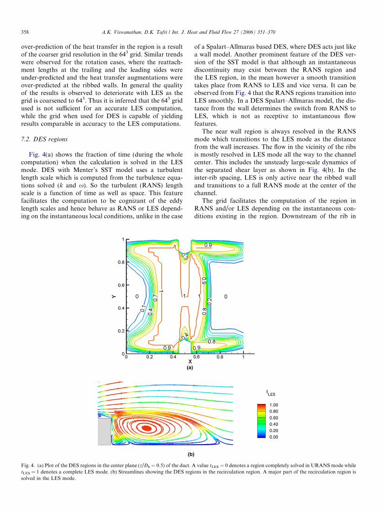
Fig. 4(a) shows the fraction of time (during the wholecomputation) when the calculation is solved in the LESmode. DES with Menter’s SST model uses a turbulentlength scale which is computed from the turbulence equa-tions solved (k and x). So the turbulent (RANS) lengthscale is a function of time as well as space. This featurefacilitates the computation to be cognizant of the eddylength scales and hence behave as RANS or LES depend-ing on the instantaneous local conditions, unlike in the case
Fig. 4. (a) Plot of the DES regions in the center plane (z/Dh = 0.5) of the duct. AtLES = 1 denotes a complete LES mode. (b) Streamlines showing the DES regisolved in the LES mode.
of a Spalart–Allmaras based DES, where DES acts just likea wall model. Another prominent feature of the DES ver-sion of the SST model is that although an instantaneousdiscontinuity may exist between the RANS region andthe LES region, in the mean however a smooth transitiontakes place from RANS to LES and vice versa. It can beobserved from Fig. 4 that the RANS regions transition intoLES smoothly. In a DES Spalart–Allmaras model, the dis-tance from the wall determines the switch from RANS toLES, which is not as receptive to instantaneous flowfeatures.
The near wall region is always resolved in the RANSmode which transitions to the LES mode as the distancefrom the wall increases. The flow in the vicinity of the ribsis mostly resolved in LES mode all the way to the channelcenter. This includes the unsteady large-scale dynamics ofthe separated shear layer as shown in Fig. 4(b). In theinter-rib spacing, LES is only active near the ribbed walland transitions to a full RANS mode at the center of thechannel.
The grid facilitates the computation of the region inRANS and/or LES depending on the instantaneous con-ditions existing in the region. Downstream of the rib in
value tLES = 0 denotes a region completely solved in URANS mode whileons in the recirculation region. A major part of the recirculation region is

A.K. Viswanathan, D.K. Tafti / Int. J. Heat and Fluid Flow 27 (2006) 351–370 359
the region of separation (Fig. 4(b)) it is observed that thecomputation is mostly carried out in the LES modewhich ensures that the unsteady physics in the separatedregion is captured accurately. Regions of low turbulencein between the ribs are completely solved in RANSmode.
7.3. Mean flow field
Early studies in turbulent channel flow (Halleen andJohnston, 1967; Lezius and Johnston, 1976) have estab-lished two important effects of rotation. When the rota-tional axis is perpendicular to the plane of mean shear,Coriolis forces have a considerable effect on the mean flowas well as on turbulent fluctuations. These effects are man-ifested as stabilization/destabilization of turbulence atleading/trailing walls and the generation of spanwise rollcells or secondary flow patterns. The secondary flow pat-terns are a direct result of the action of Coriolis forces onmean shear and are also observed in laminar flows sub-jected to system rotation.
It is well established that the production of turbulence inthe near wall region and in shear layers is caused by theexchange of momentum through intense interactionsbetween the fluctuating streamwise and cross-stream veloc-ities. When Coriolis forces act in tandem with these events,turbulence is augmented, whereas it is attenuated when thetwo act in opposition. In the ribbed duct flow in this study,both the turbulent shear layer and near wall turbulence onthe trailing surface are augmented by the direct effect ofCoriolis forces, while the opposite effect comes into playat the leading wall. The results for all three rotation num-bers follow the general trends outlined above.
The flow at the center (z = 0.5) of the duct is character-ized by a large primary recirculation region behind the rib,a small secondary eddy trapped between the primary recir-culation zone and the rib, a region of recirculation in frontof the rib, and a small eddy on top of the rib. For a non-
Fig. 5. Streamlines showing the flow in a fully developed duct as predicted bytrailing wall, while Y = 1 represents the leading wall. Flow direction is from l
rotating case all these features are similar on both theribbed walls. The reattachment of the rib separated shearlayer was observed to be in the range 4.0–4.25e for thenon-rotating case (Rau et al., 1988). The reattachmentlength predicted by DES was 4.1e which matched quite wellwith the experiments and LES predictions.
Fig. 5 shows the streamlines at the center of the duct(z = 0.5) for the three rotation cases. Rotational Coriolisforces affect the size of the recirculation zones and so theflow is asymmetric about the center y-plane of the duct.The reattachment length increases at the leading wall anddecreases at the trailing wall with rotation number. Thereattachment is observed at around 4.0e for Ro = 0.18 atthe trailing side. The size of the separation bubbledecreases to a value close to 3.6e when the rotationincreases to 0.35. On increasing the rotation further to0.67 the reattachment length remains almost the same asthe 0.35 case. On the other hand, the reattachment lengthat the leading wall increases from a value of 4.0–4.25e forthe stationary case (Ro = 0.0) to a value of 4.5e atRo = 0.18. No significant change is observed as the Ro isincreased to 0.36, but on increasing the rotation furtherto 0.67, the recirculation region is observed to increase toa value of around 6.7e, and as a result it merges with therecirculation region in front of the next rib.
The reattachment lengths for the rotating cases are con-sistent with the LES predictions (Abdel-Wahab and Tafti,2004a,b). Fig. 6 shows the comparison of the flowfield aspredicted by LES, DES and URANS. The separationand reattachment downstream of the rib is predicted accu-rately by DES and the reattachment length is in agreementwith LES both at the leading and the trailing walls. How-ever URANS overpredicts the reattachment lengths bothat the leading as well as the trailing wall. Overpredictionof the reattachment lengths is a result of the inability ofthe SST model to account for the effects of Coriolis forces,whereas in DES, the effect of Coriolis forces is captured inthe resolved scales.
DES SST at Z = 0.5. Ro = 0.18 (a); 0.35 (b); 0.67 (c). Y = 0 represents theeft to right.

Fig. 6. Streamlines showing the flow in a fully developed duct rotating at Ro = 0.35 at Z = 0.5 as predicted by (a) LES; (b) DES SST; (c) URANS SST.Y = 0 represents the trailing wall, while Y = 1 represents the leading wall. Flow direction is from left to right.
3 For DES, the magnitude of the modeled stresses vary from val-ues < 10�1% on top of the ribs where the grid is fine to around 2% near theperiodic face where the grid density is coarser. For URANS, themagnitude of the modeled stresses is as high as the resolved componentin some regions of the flow.
360 A.K. Viswanathan, D.K. Tafti / Int. J. Heat and Fluid Flow 27 (2006) 351–370
The secondary flow in between the two ribs (Fig. 7)shows the presence of a pair of corner vortices in eachquadrant when the ribbed duct is stationary. Similar vorti-ces were observed by Liou et al. (2001) in their experiments.As the rotation increases to Ro = 0.18, the vortices on theleading side disappear, while the vortices at the trailing wallgrow and move towards the center of the duct. As the rota-tion increases further the two vortices merge and grow big-ger. At Ro = 0.67, the vortices occupy almost 80% of thechannel height as observed in Fig. 7(d).
While Fig. 7 shows the structure of the secondary flow,Fig. 8 shows the magnitude of the secondary flows (v, w
velocities) for the stationary and the three rotation casesin the cross-section of the duct on top of the rib. The v-and w-velocities are plotted individually in each half ofthe span. Above the rib, the constriction posed by the ribresults in flow being pushed towards the channel center,both at the center of the span and near the side wall. Inaddition to this effect, a spanwise flow is setup towardthe center and toward the side wall which is representedby the high positive impingement w-velocities at the sidewall. As rotation increases, the strength of the secondaryimpingement flow at the trailing side increases while itdecreases at the leading side, which is evident from theintrusion of the high v-velocities towards the leading sidenear the side wall. The asymmetry in the w-velocity alsoincreases as the rotation increases.
7.4. Turbulent flow characteristics
A comparison of the instantaneous coherent vorticity(Joeng and Hussain, 1995) as predicted by 1283 LES, 643
DES and 643 URANS is shown in Fig. 9. These plots givean idea of the flow structures resolved by the three schemes.It is observed that the magnitude of coherent vorticity andthe flow characteristics predicted by DES is consistent withthe magnitudes predicted by LES on a much finer grid. Pre-dictions by URANS show lower vorticity levels as com-
pared to LES and DES, both in the center of the duct aswell as the inter-rib region. Thus the small modificationin the length scales in the URANS model, which convertsit into an equivalent DES model, substantially improvesthe fidelity of the simulation.
A comparison of the turbulent kinetic energies (TKE)predicted by the DES, LES and the URANS schemes areshown in Fig. 10. It is observed that the resolved compo-nent of TKE is significantly larger than the modeled com-ponent in the DES computation almost in the entire flowfield. So the resolved component of TKE is consideredfor comparison for the DES and the LES cases, while thesum of the resolved and modeled components are consid-ered for the URANS case.3 A comparison of the TKE ontop of the rib shows that the values resolved by DES com-pare well with that resolved by LES for all the three rota-tion cases. Localized peaks are observed at the trailing walland the leading wall corresponding to the shear layer ontop of the rib. The peak TKE at the trailing wall is around0.28 for Ro = 0.18. The value is almost constant as therotation increases to a value of 0.35 but shows a dramaticincrease as the Ro increases further to 0.67 where the peakis around 0.38. At the leading wall the peak TKE reducesfrom a value of about 0.2 for the lowest rotation case toabout 0.15 for the highest rotation case. The trend pre-dicted by URANS at low rotation partly agrees with theLES computations towards the center of the channel, butthe peaks in the shear layer are underpredicted by nearly50%. At higher rotation cases the TKE are underpredictedthrough the complete height of the duct.
TKE values in between the ribs show similar trends. Thelocation is just downstream of the reattachment point at
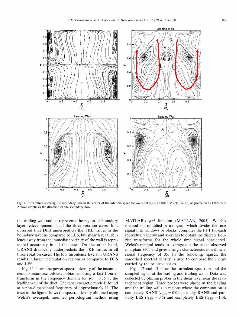
Fig. 7. Streamlines showing the secondary flow in the center of the inter-rib space for Ro = 0.0 (a); 0.18 (b); 0.35 (c); 0.67 (d) as predicted by DES SST:Arrows emphasis the direction of the secondary flow.
A.K. Viswanathan, D.K. Tafti / Int. J. Heat and Fluid Flow 27 (2006) 351–370 361
the trailing wall and so represents the region of boundarylayer redevelopment in all the three rotation cases. It isobserved that DES underpredicts the TKE values in theboundary layer as compared to LES, but shear layer turbu-lence away from the immediate vicinity of the wall is repre-sented accurately in all the cases. On the other hand,URANS drastically underpredicts the TKE values in allthree rotation cases. The low turbulence levels in URANSresults in larger recirculation regions as compared to DESand LES.
Fig. 11 shows the power spectral density of the instanta-neous streamwise velocity, obtained using a fast Fouriertransform in the frequency domain for Ro = 0.35 at theleading wall of the duct. The most energetic mode is foundat a non-dimensional frequency of approximately 11. Theinset in the figure shows the spectral density obtained usingWelch’s averaged, modified periodogram method using
MATLAB’s psd function (MATLAB, 2005). Welch’smethod is a modified periodogram which divides the timesignal into windows or blocks, computes the FFT for eachindividual window and averages to obtain the discrete Fou-rier transforms for the whole time signal considered.Welch’s method tends to average out the peaks observedin a plain FFT and gives a single characteristic non-dimen-sional frequency of 35. In the following figures, thesmoothed spectral density is used to compare the energycarried by the resolved scales.
Figs. 12 and 13 show the turbulent spectrum and thesampled signal at the leading and trailing walls. Data wascollected by placing probes in the shear layer near the reat-tachment region. Three probes were placed at the leadingand the trailing walls in regions where the computation iscompletely RANS (tLES = 0.0), partially RANS and par-tially LES (tLES = 0.5) and completely LES (tLES = 1.0).

Fig. 8. Secondary flow contours on the rib for Ro = 0.0 (a); 0.18 (b); 0.35 (c); 0.67 (d) as predicted by DES SST. The contours show the effect of rotationon the secondary flow in the cross-section. The arrows qualitatively represent the effect of rotation on the magnitude of the v- and w-velocities.
362 A.K. Viswanathan, D.K. Tafti / Int. J. Heat and Fluid Flow 27 (2006) 351–370
From the signals it is observed that the DES computationshows more unsteadiness, hence more resolved energy, ascompared to the URANS computation. A one to one com-parison can be made at the location at which tLES = 0.0 (fullURANS in DES approach) versus the same location in theURANS calculation in Figs. 12 and 13. At the leading wallthe resolved peak energy between the two cases varies bynearly two orders of magnitude, whereas at the trailing wallthe ratio is about 5. Larger differences between DES andURANS is found at locations where DES operates in fullLES mode (tLES = 1.0). Comparison of LES with DES atlocations where tLES = 1.0 (full LES mode) shows that thepeak resolved energy is of comparable magnitude – at thetrailing wall, the LES peak is at 4 whereas the DES peaksat 4.5. At the leading wall, the DES peak energy is higherat 1.5 than the corresponding LES, which is at 0.6, indicat-
ing that the level of turbulent fluctuations is higher at thislocation in the DES calculation. This is suspected to becaused by a slight shift in the shear layer trajectory.
Figs. 12 and 13 bring out an important observation, thatfor the same resolution, the DES framework allows a muchlarger part of the energy spectrum or scales to be resolvedon the grid. While URANS picks up the most energeticmodes, only a fraction of the energy is present in the gridscales. This would not be a problem if the models were trueto the physics, which for rotating ducts is not the case. TheSST model does not include the effect of Coriolis forces onturbulence, but the consequence of that shortcoming is feltmuch more in the URANS model than in DES because alarge fraction of the modal energy is resolved on the gridby DES and the effect of Coriolis forces is included directlythrough the momentum equations.

Fig. 9. Coherent vorticity contours for the (a) LES 1283; (b) DES 643; (c) URANS 643 for Ro = 0.35 show the scales resolved of the three schemes atz = 0.5.
A.K. Viswanathan, D.K. Tafti / Int. J. Heat and Fluid Flow 27 (2006) 351–370 363
7.5. Mean heat transfer
The heat transfer trends at the leading and trailing wallsare similar to the trends observed at the ribbed walls for thestationary case. The augmentation ratio is high in front ofthe rib as a result of the unsteady vortices in this region.These secondary vortices continuously transport coolerfluid from the mainstream to the ribbed wall increasingthe heat transfer coefficient. Immediately behind the rib,a secondary recirculation is trapped between the wall andthe primary recirculation zone. Although the action ofthe secondary eddy causes some localized augmentationin this region, the overall augmentation is low and similarto that in a smooth duct. Further downstream, the heattransfer coefficient increases steadily as the vortices fromthe separated shear layer impinge on the wall.
Fig. 14 shows the heat transfer at the leading (upperhalf) and the trailing walls (lower half) for the three rota-tion cases. As the rotation number is increased, an increasein the heat transfer is observed at the trailing wall, espe-cially in regions immediately upstream of the rib and nearthe reattachment point. This is countered by a decrease atthe leading wall in the corresponding regions. The heattransfer augmentation in the region upstream of the reat-tachment point at the trailing wall increases from 4.4 forRo = 0.18 to 4.8 for Ro = 0.35 and 5.6–6.0 for Ro = 0.67.At the leading wall the heat transfer upstream of the reat-tachment point is observed to decrease from 2.8 forRo = 0.18 to 1.6 for Ro = 0.35 and 0.67 respectively.
Fig. 15 shows a comparison of the DES and theURANS with LES results at Ro = 0.35. This shows thatthe URANS under-predicts the heat transfer at the trailing

Fig. 10. TKE values as predicted by the DES, LES and the URANS cases for the three rotation cases on top of the ribs and in between the ribs.
Fig. 11. Power spectral density at the leading wall for Ro = 0.35 with DES. The inset shows the equivalent semi-log scale representation, which is used tocompare the relative magnitudes of the dominant frequency in Figs. 12 and 13.
364 A.K. Viswanathan, D.K. Tafti / Int. J. Heat and Fluid Flow 27 (2006) 351–370
side, where the turbulence is enhanced by rotation. Theheat transfer augmentation predicted by DES agrees quitewell with the LES computations. The peak heat transfer onthe trailing wall in the region of shear layer reattachment is
shifted away from the center of the duct due to the effect ofsecondary flows and is captured by all three methods.However, the URANS predicts this region further down-stream because of the larger reattachment length. Heat

Fig. 12. Turbulence spectrum and the signal sampled for 5.0 non-dimensional time units at the leading wall for Ro = 0.35.
A.K. Viswanathan, D.K. Tafti / Int. J. Heat and Fluid Flow 27 (2006) 351–370 365
transfer augmentations at the trailing wall reach valuesclose to 5.2 immediately upstream of the rib where theunsteady vortices enhance the heat transfer. Both DESand URANS tend to over-predict the spatial extent of thisregion.
The flow at the leading wall is more stable than the flowat the trailing wall and so the overall heat transfer at theleading wall is almost half the heat transfer at the trailingwall. Upstream of the rib, heat transfer levels are almost2.8 times that observed in a smooth duct case. Once again,

Fig. 13. Turbulence spectrum and the signal sampled for 5.0 non-dimensional time units at the trailing wall for Ro = 0.35.
366 A.K. Viswanathan, D.K. Tafti / Int. J. Heat and Fluid Flow 27 (2006) 351–370
both DES and URANS overpredict the extent and aug-mentation in this region. The heat transfer levels drop tovalues close to the smooth channel heat transfer valuesimmediately behind the rib, but the augmentation increasesto values close to 1.6 downstream of the reattachmentpoint.
The trends predicted by DES are consistent with theLES results (Abdel-Wahab and Tafti, 2004a,b), with theexception of the region immediately upstream of the ribwhere higher levels of heat transfer are predicted. Similarresults were observed by Viswanathan and Tafti (2004,2005c) in a stationary duct where a larger heat transfer aug-

Fig. 14. Heat transfer augmentation (Nu/Nu0) predicted at the leading and the trailing walls by DES SST for Ro = 0.18 (a); 0.35 (b); 0.67 (c). Flowdirection is from left to right.
Fig. 15. Heat transfer augmentation (Nu/Nu0) predicted at the leading and the trailing walls for the Ro = 0.35 case by (a) LES; (b) DES SST; (c) URANSSST. Flow direction is from left to right.
A.K. Viswanathan, D.K. Tafti / Int. J. Heat and Fluid Flow 27 (2006) 351–370 367
mentation was observed immediately upstream of the rib.On the other hand URANS results show a lot of discrep-ancy. The most prominent deviation from LES is theunder-prediction of the heat transfer at the trailing wallof the duct. The heat transfer distributions at the ribbedwalls are also much smoother than LES and DESpredictions.
The secondary flows in the stationary and the rotationcases play a major role in the heat transfer at the side walls.Along the smooth (side) walls the heat transfer increases onmoving from the trailing wall and reaches a maximum atthe top front corner of the rib as a result of the secondaryflow impingement on the wall. The heat transfer decreaseson the side walls towards the center of the channel. Thoughthe heat transfer patterns are the same for the stationaryand the rotation cases the magnitudes of heat transfer area function of the rotation.
For Ro = 0.18 (Fig. 16) the secondary flow impingementresults in levels of heat transfer as high as seven times thatin a smooth channel at the trailing wall, at the corner of therib and the side wall. The heat transfer decreases to valuesclose to 2.0 towards the center of the duct. On movingtowards the leading wall the heat transfer decreases further
and drops to values lower than unity near the leading wallof the side wall. However secondary flow impingementnear the corner of the ribs locally results in higher heattransfer. As the rotation increases higher heat transfer isobserved near trailing wall and lower hear transfer regionsmove closer to the leading wall. This behavior is consistentwith the secondary flow features observed, i.e., stronger theimpingement more is the heat transfer at the side walls.
Fig. 17 compares the side wall heat transfer predicted byDES and URANS with LES for Ro = 0.35. The DES pre-dictions compare well with LES. URANS predicts compa-rable trends except that a noticeably larger augmentationregion is predicted near the rib at the trailing wall andthe augmentation ratio is also underpredicted at the centerof the duct and in the vicinity of the trailing wall.
Fig. 18 shows a gradual increase in the average heattransfer augmentation at the side walls as the rotationnumber increases from 0 to 0.67. DES predicts these trendsaccurately but slightly underpredicts the augmentationcompared to LES. URANS severely underpredicts the sidewall heat transfer at Ro = 0.18 and 0.35, while the agree-ment is comparatively better at the highest rotationnumber.

Fig. 16. Heat transfer augmentation (Nu/Nu0) predicted at the side wall by DES SST for the Ro = 0.18 (a); 0.35 (b); 0.67 (c). Flow direction is from left toright.
Fig. 17. Heat transfer augmentation (Nu/Nu0) predicted at the side wall for the Ro = 0.35 case by (a) LES; (b) DES SST; (c) URANS SST. Flow directionis from left to right.
Ro
Nu
/Nu
0
0 0.2 0.4 0.61
2
3
DES(U)RANSLES
Fig. 18. Side wall heat transfer predicted by LES, DES and URANS forthe various rotation cases.
368 A.K. Viswanathan, D.K. Tafti / Int. J. Heat and Fluid Flow 27 (2006) 351–370
The effect of rotation is more prominent at the leadingand the trailing walls. Results for averaged Nusselt num-bers on the leading and trailing faces for the three rotationnumbers are compared with the experiments of Liou et al.(2001), Parsons et al. (1994), and Wagner et al. (1992). Theexperimental data of Liou et al. (2001) is at Re = 10,000 fore/Dh = 0.136 and P/e = 10 and Parsons et al. (1994) data isobtained at Re = 5000 for e/Dh = 0.125 and P/e = 10. Thedata of Wagner et al. (1992) includes the effects of buoy-ancy with a density ratio = 0.04 for a staggered ribarrangement with e/Dh = 0.1 and P/e = 10 at Re =25,000. Wagner’s data includes the effects of centrifugalbuoyancy which increase trailing wall heat transfer as therotation number increases. In all cases, fully developeddata is extracted for comparison. Fig. 19 compares theoverall heat transfer augmentations at the leading and trail-ing walls predicted by DES and URANS cases, with theLES computations and experimental results. DES predic-tions agree well with experiments and LES except for thetrailing side at Ro = 0.18, where the augmentation is

Ro
Nu
/Nu 0
0 0.2 0.4 0.60
1
2
3
4
5
6
Liou et al.
Wagner Bo = 0.04
Parsons et al.
LESDESURANSTrailing Side
Leading Side
Fig. 19. Comparison of average Nusselt number augmentation ratios atthe leading and trailing sides with experiments.
A.K. Viswanathan, D.K. Tafti / Int. J. Heat and Fluid Flow 27 (2006) 351–370 369
underpredicted by 11% compared to Parson’s data andabout 15% compared to LES. On the other hand, URANSsubstantially underpredicts the trailing wall augmentation,by as much as 30% compared to LES, at the high rotationnumbers of 0.35 and 0.67. Prediction accuracy of URANSis similar to that of DES at the leading wall which is within10% of LES.
8. Conclusions
Results from DES and URANS of a fully developed flowin a 90� ribbed duct are presented for three rotation cases –Ro = 0.18, 0.35 and 0.67 at a Reynolds number of 20,000.The computations were performed on a 643 mesh tested ear-lier for a stationary case which is almost an order of magni-tude less expensive than the analogous LES computation ona 1283 mesh (Abdel-Wahab and Tafti, 2004a,b).
The effect of rotation is observed by the increase in theunsteadiness at the trailing wall due to which the reattach-ment length decreases. Secondary flow impingement isobserved to become stronger as rotation increases. Theseflow features result in an increase in the heat transfer atthe trailing wall. The peak heat transfer level increasesfrom a value of about 3.0 for the stationary duct to a valueof about 6.0 for the largest rotation. The overall heat trans-fer at the trailing wall increases by almost a factor of 1.5 asthe system is rotated from rest to Ro = 0.67.
At the leading wall the opposite effect is observed. Rota-tion damps turbulence at the leading wall resulting in largerrecirculation regions. It is observed that the recirculationregion downstream of the rib almost overlaps the recircula-tion region upstream of the next rib. This results in low lev-
els of heat transfer at the leading wall. The heat transferdistribution drops to values close to that in a smooth ductfor the highest rotation considered.
The heat transfer at the side walls show distributionssimilar to a stationary duct. The heat transfer is high atthe corner of the rib, which is due to the impingement ofthe secondary flows on the side walls. The heat transferdecreases on moving from the trailing wall to the leadingwall. Rotation increases the magnitude of the secondaryflows and increases the heat transfer augmentation on theside walls.
The flow and heat transfer distribution predicted by theSST DES case is consistent with the LES predictions.Though higher heat transfer is predicted immediatelyupstream of the rib, the distribution in the other regionsare accurate. The overall heat transfer predicted also matchwell with the LES predictions and the experimental obser-vations. URANS fails to capture the effects of the Coriolisforces at the trailing walls and underpredicts the heattransfer.
In summary, it is concluded that DES accurately pre-dicts the physics of the rotation dominated flow, in addi-tion to accurately predicting separation and reattachmentand unsteady vortex induced secondary motions. The maincontribution of this paper is in establishing that DES, likeLES, can produce good quality results at a much lower costthan an equivalent well-resolved LES. The payoffs of DESare expected to be more at higher Reynolds numbers.
References
Abdel-Wahab, S., Tafti, D.K., 2004a. Large eddy simulations of flow andheat transfer in a 90� ribbed duct with rotation – effect of Coriolis andcentrifugal buoyancy forces. J. Turbomach. 126 (4), 627–636.
Abdel-Wahab, S., Tafti, D.K., 2004b. Large eddy simulations of flow andheat transfer in a 90� ribbed duct with rotation. Effect of coriolisforces, GT2004-53796, ASME Turbo Expo: 2004, Vienna, Austria.
Abdel-Wahab, S., Tafti, D.K., 2004c. Large eddy simulation of flow andheat transfer in a staggered 45� ribbed duct. Paper no. GT2004-53800,ASME Turbo Expo: 2004, Vienna, Austria, 14–17 June 2004.
Amano, R.S., Goel, P., 1995. Computation of turbulent flow beyondbackward steps using Reynolds stress closure. AIAA J 23, 1356.
Bradshaw, P., 1969. The analogy between streamline curvature andbuoyancy in turbulent shear flow. J. Fluid Mech. 36 (Part 1), 177–191.
Bradshaw, P., 1988. In: Kline, S.J., Afghan, N.H. (Eds.), Effects of ExtraStrain – Review, Near Wall turbulence, Zoran Zaric MemorialConference. Hemisphere Publishing Corporation, pp. 106–122.
Bo, T., Iacovides, H., Launder, B.E., 1995. Developing buoyancy-modified turbulent flow in ducts rotating in orthogonal mode. Trans.ASME 177, 474–484.
Chima, R.V., 1996. A k–x turbulence model for quasi-three dimensionalturbo machinery flows, AIAA 96-0258.
Driver, D., Seegmiller, H.L., 1985. Features of reattaching turbulent shearlayer in divergent channel flow. AIAA J. 23, 162–171.
Forsythe, J.R., Squires, K.D., Wurtzler, K.E., Spalart, P.R., 2002.Detached-eddy simulation of fighter aircraft at high alpha, AIAAPaper 2002-0591.
Halleen, R.M., Johnston, J.P., 1967. The influence of rotation of flow in along rectangular channel – an experimental study, Report MD-18,Thermosciences Division, Dept. of Mech. Eng., Stanford University.
Hanjalic, K., Launder, B.E., 1980. Sensitizing the dissipation equation toirrotational strains. ASME J. Fluids Eng. 102, 34.

370 A.K. Viswanathan, D.K. Tafti / Int. J. Heat and Fluid Flow 27 (2006) 351–370
Hellsten, A., 1998. Some improvements in Menter’s k–x SST turbulencemodel, AIAA 98-2554.
Howard, J.H.G., Patankar, S.V., Bordynuik, R.M., 1980. Flow predictionin rotating ducts using Coriolis-modified turbulence models. ASME J.Fluids Eng. 102, 456–461.
Iacovides, H., Launder, B.E., 1991. Parametric and numerical study offully developed flow and heat transfer in rotating rectangular ducts. J.Turbomach. 133, 331–338.
Incropera, F.P., Dewitt, D.P., 2002. Fundamentals of Heat and MassTransfer, fifth ed. John Wiley and Sons, New York.
Ishigaki, H., 1996. Analogy between turbulence flows in curved pipes andorthogonally rotating pipes. J. Fluid Mech. 307, 1–10.
Joeng, J., Hussain, F., 1995. On the identification of a vortex. J. FluidMech. 285, 69–94.
Kapadia, S., Roy, S., Wurtlzer, K., 2003. Detached eddy simulation over areference Ahmed car model, AIAA 2003-0857.
Launder, B.E., Priddin, C.H., Sharma, B.I., 1977. The calculation ofturbulent boundary layers on spinning and curved surfaces. ASME J.Fluids Eng. (March), 231–239.
Lezius, D.K., Johnston, J.P., 1976. Roll-cell instabilities in rotating laminarand turbulent channel flows. J. Fluid Mech. 77 (Part 1), 153–175.
Lin, Y.L., Shih, T.I.-P., Stephens, M.A., Chyu, M.K., 2001. A numericalstudy of flow and heat transfer in a smooth and a ribbed U-duct withand without rotation. ASME J. Heat Transfer 123, 219–232.
Liou, T.M., Chen, M.Y., Tsai, M.H., 2001. Fluid flow and heat transfer ina rotating two-pass square duct with in-line 90� ribs, ASME TurboExpo: 2001-GT-0185.
MATLAB, 2005. Release Notes for Release 14 with Service Pack 3.Menter, F.R., 1992. Improved two-equation k–x turbulence models for
aerodynamic flows, NASA Technical Memorandum 103975.Menter, F.R., 1993. Zonal two equation k–x turbulence models for
aerodynamic flows, AIAA Paper 93-2906.Murata, A., Mochizuki, S., 1999. Effect of cross-sectional aspect ratio on
turbulent heat transfer in an orthogonally rotating rectangular smoothduct. Int. J. Heat Mass Transfer 42, 3803–3814.
Murata, A., Mochizuki, S., 2000. Large eddy simulation with a dynamicsubgrid-scale model of turbulent heat transfer in an orthogonallyrotating rectangular duct with transverse rib turbulators. Int. J. HeatMass Transfer 43, 1243–1259.
Nikitin, N.V., Nicoud, F., Wasistho, B., Squires, K.D., Spalart, P.R.,2000. An approach to wall modeling in large-eddy simulations. Phys.Fluids 12 (7), 1629–1632.
Parsons, J.A., Han, J.C., Zang, Y.M., 1994. Wall heating effect on localheat transfer in a rotating two-pass square channel with 90� ribturbulators. Int. J. Heat Mass Transfer 37, 1411–1420.
Prakash, C., Zerkle, R., 1995. Prediction of turbulent flow and heattransfer in a ribbed rectangular duct with and without rotation. J.Turbomach. 117, 255–264.
Rau, G., Cakan, M., Moeller, D., Arts, T., 1988. The effect of periodic ribson local aerodynamic and heat transfer performance of a straightcooling channel. ASME J. Turbomach. 120, 368–375.
Rigby, D.L., 1998. Prediction of heat and mass transfer in a rotatingribbed coolant passage with a 180 degree turn, 98-GT-329, Interna-tional Gas Turbine and Aeroengine Congress and Exhibition, Stock-holm, Sweden, 2–5 June.
Rodi, W., Scheuerer, G., 1983. Calculation of curved shear layers withtwo-equation turbulence models. Phys. Fluids 26 (6).
Schweighofer, J., Hellsten, A., 1999. Computations of viscous flow aroundthe HSVA-1 tanker using two versions of k–x turbulence model.Helsinki University of Technology, Laboratory of Aerodynamics,Report B-51.
Sewall, E.A., Tafti, D.K., 2004a. Large eddy simulation of the developingregion of a stationary ribbed internal turbine blade cooling channel,Paper no. GT2004-53832, ASME Turbo Expo: 2004, Vienna, Austria,14–17 June 2004.
Sewall, E.A., Tafti, D.K., 2004b. Large eddy simulations of the developingregion of a rotating ribbed internal turbine blade cooling channel,Paper no. GT2004-53833, ASME Turbo Expo: 2004, Vienna, Austria,14–17 June 2004.
Sewall, E.A., Tafti, D.K., 2006. Large eddy simulation of flow and heattransfer in the 180� bend region of a stationary ribbed gas turbineinternal cooling duct. J. Turbomach. 128.
Sewall, E.A., Tafti, D.K. Large eddy simulation of flow and heat transferin the developing region of a rotating gas turbine blade internal coolingduct with coriolis forces and buoyancy forces, GT 2005-68519, ASMETurbo Expo 2005, Reno, J. Turbomach., accepted for publication.
Sewall, E.A., Tafti, D.K., Graham, A., Thole, K.A., 2006. Experimentalvalidation of large eddy simulation of flow and heat transfer in astationary ribbed duct. Int. J. Heat Fluid Flow 27 (2), 243–258.
Spalart, P.R., Jou, W.H., Streletes, M., Allmaras, S.R., 1997. Commentson the feasibility of LES for wings and a hybrid RANS/LES approach.In: Liu, C., Liu, Z. (Eds.), First AFSOR Int. Conf. on DNS/LES, 4–8August 1997, Advances in DNS/LES. Greyden Press, Columbus, OH.
Speziale, G., Ngo, T., 1988. Numerical solution of turbulent flow past abackward-facing step using a nonlinear k–e model. Int. J. Eng. Sci. 26,1099–1112.
Squires, K.D., Forsythe, J.R., Morton, S.A., Blake, D.C., Serrano, M.,Wurtzler, K.E., Strang, W.Z., Tomaro, R.F., Spalart, P.R., 2002.Analysis of full aircraft with massive separation using detached-eddysimulation. In: Proceedings of the High Performance ComputingModernization Program 2002 Users Group Conference, Austin, Texas.
Stephens, M.A., Shih, T.I.-P., Civinskous, K.C., 1996. Computations offlow and heat transfer in a rotating U-shaped square duct with smoothwalls, AIAA 96-3161.
Strelets, M., 2001. Detached eddy simulation of massively separated flows,AIAA 2001-0879.
Tafti, D.K., 2001. GenIDLEST – A scalable parallel computational toolfor simulating complex turbulent flowsProc. ASME Fluids Engineer-ing Division, FED, vol. 256. ASME-IMECE, New York.
Tafti, D.K., 2005. Evaluating the role of subgrid stress modelling in aribbed duct for the internal cooling of turbine blades. Int. J Heat FluidFlow 26 (1), 92–104.
Viswanathan, A.K., Tafti, D.K., 2004. Detached eddy simulation ofturbulent flow and heat transfer in a duct, HT-FED2004-56152, 2004ASME Heat Transfer/Fluids Engineering Summer Conference, Char-lotte, 11–15 July.
Viswanathan, A.K., Tafti, D.K., 2005a. Detached eddy simulation of flowand heat transfer in a stationary internal cooling duct with skewed ribs,GT 2005-68118, ASME Turbo Expo: 2005, Reno-Tahoe, Nevada,USA, 6–9 June 2005.
Viswanathan, A.K., Tafti, D.K., 2005b. Large eddy simulation in a ductwith rounded skewed ribs, GT 2005-68117, ASME Turbo Expo: 2005,Reno-Tahoe, Nevada, USA, 6–9 June 2005.
Viswanathan, A.K., Tafti, D.K., 2005c. Detached eddy simulation ofturbulent flow and heat transfer in a duct. J. Fluids Eng. 127, 888–896.
Viswanathan, A.K., Tafti, D.K., 2006. Detached eddy simulation ofturbulent flow and heat transfer in a two-pass internal cooling duct.Int. J Heat Fluid Flow 27 (1), 1–20.
Viswanathan, A.K., Tafti, D.K., Abdel-Wahab, S., 2005. Large eddysimulation of flow and heat transfer in an internal cooling duct withhigh-blockage 45� staggered ribs, GT 2005-68086, ASME Turbo Expo2005, Reno-Tahoe, Nevada, USA, 6–9 June 2005.
Wagner, J.H., Johnson, B.V., Graziani, R.A., Yeh, F.C., 1992. Heattransfer in rotating serpentine passages with trips normal to the flow. J.Turbomach. 114, 847–857.
Watanabe, K., Takahashi, T., 2002. LES simulation and experimentalmeasurement of fully developed ribbed channel flow and heat transfer.In: Proc. ASME Turbo Expo: 2002-GT-30203.
Wilcox, D.C., Chambers, T.L., 1977. Streamline curvature effects onturbulent boundary layers. AIAA J. 15 (4).
Related Documents