GE Consumer & Industrial Electrical Distribution AF-650 GP TM General Purpose Drive Brake Resistor Design Guide

Welcome message from author
This document is posted to help you gain knowledge. Please leave a comment to let me know what you think about it! Share it to your friends and learn new things together.
Transcript

8/20/2019 DET-700
http://slidepdf.com/reader/full/det-700 1/30
GE Consumer & IndustrialElectrical Distribution
AF-650 GPTM
General Purpose Drive
Brake Resistor Design Guide

8/20/2019 DET-700
http://slidepdf.com/reader/full/det-700 2/30
Contents
1 How to Read this Design Guide
How to Read this Design Guide
Abbreviations
2 Safety and Conformity
Safety Precautions
CE Conformity and Labelling
3 Introduction
Description of the Brake System
4 How to Choose a Brake Resistor
Flat Packs
Wire Wound
5 Application Examples
Examples
Example 1 - Conveyor Belt
Example 2 - Centrifuge
Continuous Braking
6 Calculation of the Brake ResistorBrake Setup
Calculation of Brake Resistor Values
Calculation of Braking Power
Calculation of the Brake Resistor Peak Power
Calculation of the Brake Resistor Average Power
Braking of Inertia
7 Installation
Brake Cable
Protective Functions During Installation
AF-650

8/20/2019 DET-700
http://slidepdf.com/reader/full/det-700 3/30
AF-650
1

8/20/2019 DET-700
http://slidepdf.com/reader/full/det-700 4/30
1 How to Read this Design Guide
1.1.1 How to Read this Design Guide
This Design Guide will introduce all aspects of Brake Resistors for your AF-650 GP; From choosing the right Brake Resistor
how to install it and how to programme the Frequency converter.
GE technical literature is also available online at www.geelectrical.com/drives
1.1.2 Symbols
Symbols used in this manual:
NB!
Indicates something to be noted by the reader.
Indicates a general warning.
Indicates a high-voltage warning.
✮ Indicates default setting
AF-650

8/20/2019 DET-700
http://slidepdf.com/reader/full/det-700 5/30
1.1.3 Abbreviations
Alternating current AC
American wire gauge AWGAmpere/AMP ACurrent limit ILIM
Degrees Celsius °CDirect current DCDrive Control Tool PC Software DCT 10Drive Dependent D-TYPEElectro Magnetic Compatibility EMCElectronic Thermal Overload Elec. OLGram gHertz HzKilohertz kHzMeter m
Millihenry Inductance mHMilliampere mAMillisecond msMinute minNanofarad nFNewton Meters NmNominal motor current IM,N
Nominal motor frequency f M,N
Nominal motor power PM,N
Nominal motor voltage UM,N
Parameter par.Protective Extra Low Voltage PELV
Printed Circuit Board PCBRated Inverter Output Current IINV
Revolutions Per Minute RPMRegenerative terminals RegenSecond sSynchronous Motor Speed ns
Torque limit TLIM
Volts V
AF-650
1

8/20/2019 DET-700
http://slidepdf.com/reader/full/det-700 6/30
2 Safety and Conformity
2.1 Safety Precautions
Equipment containing electrical components may not be disposed of togetherIt must be separately collected with electrical and electronic waste according
AF-650 GP
Design Guide
2.1.1 CE Conformity and Labelling
What is CE Conformity and Labelling?
The purpose of CE labelling is to avoid technical trade obstacles within EFTA and the EU. The EU has introduced the CE la
a product complies with the relevant EU directives. The CE label says nothing about the specifications or quality of the prod
by three EU directives:
The low-voltage directive (73/23/EEC)
Frequency converters must be CE labelled in accordance with the low-voltage directive of January 1, 1997. The directiv
appliances used in the 50 - 1000 V AC and the 75 - 1500 V DC voltage ranges. GE CE-labels in accordance with the directiv
upon request.
AF-650

8/20/2019 DET-700
http://slidepdf.com/reader/full/det-700 7/30
Warnings
When in use the brake res istor surface temperature rises. DO NOT touch the brake resistor during operatio
Never work on a brake resistor in operation.
NB!
Never attempt to repair a defective brake resistor.
AF-650
2

8/20/2019 DET-700
http://slidepdf.com/reader/full/det-700 8/30
3 Introduction
3.1.1 Description of the Brake System
When the speed reference of a frequency converter is reduced, the motor acts as a generator and brakes. When a moto
to the frequency converter which is collected in the intermediate circuit. The function of the brake resistor is to provide a
braking, thereby ensuring that the braking power is absorbed by the brake resistor.
If a brake resistor was not used, the intermediate circuit voltage of the frequency converter would continue to increase, unt
of using a brake resistor is it enables braking of a heavy load quickly, e.g. on a conveyor belt.
GE has chosen a solution in which the brake resistor does not form an integral part of the frequency converter.
This offers the user the following advantages:
- The resistor time cycle can be selected as required
- The heat developed during braking can be conveyed beyond the panel cabinet to allow the energy to be used
- There is no overheating of the electronic components, even if the brake resistor is overloaded
GE offers a range of brake resistors for AF-650 GP.
This Design Guide describes how to choose the right brake resistor for an application. Alternative to using a brake resisto
can be applied depending on the braking profile of the application. The alternative braking methods can be found in the
AF-650

8/20/2019 DET-700
http://slidepdf.com/reader/full/det-700 9/30
AF-650
4

8/20/2019 DET-700
http://slidepdf.com/reader/full/det-700 10/30
4 How to Choose a Brake Resistor
The GE brake resistor programme consists of two types of resistors, flat packs and wire wound - see pictures below.
Illustration 4.1: Wire Wound
Illustration 4.2: Flat Pack
4.1.1 Flat Packs
The flat pack brake resistors ( see Illustration 4.2) for the AF-650 GP series is a safe and compact solution for the custome
the resistor is self protecting as a fuse. This means short circuit proof, no fault to frame, no melting of casing and self exting
aluminum and is IP65 tight.
With the compact flat pack resistor, it is possible to mount the resistor on the rear of a AF-650 GP frequency converter.
The flat pack resistor portfolio covers the lower power range from 0.75 - 7.5 kW (200 - 240 V & 380 - 480 V) - and intende
4.1.2 Wire Wound
The GE wire wound resistor (see Illustration 4.1) consist of fully welded wire wound ceramic resistors. The base material
resistant ceramic, called Corderite. This ensures a resistor which is suitable for pulse loads between 10 - 20 times or mo
is used in frequent braking applications such as cranes, hoists and elevators.
To simplify the selection of the wire wound brake resistor GE has chosen to offer two sizes for each drive across the pow
480 V).
The overall sizes are based on the duty cycle (10% and 40%) which is the proportion between the process time and the
resistor is applied it is able to absorb/brake away the peak power for 10% of the period. The remaining 90% of the pe
Depending on the size the periods for the wire wound resistors are 120, 300 and 600 seconds.
The following chapter lists the 10% and 40% brake resistors available for the AF-650 GP drives.
If the optimum brake resistor must be selected it is necessary to know how often and how much the motor is to brak
examples can be found in chapter 6 and 7.
AF-650

8/20/2019 DET-700
http://slidepdf.com/reader/full/det-700 11/30
H o r i z o n t a l o r v e r t i c a l
m o v e m e n t ?
L o w o r h i g h
i n e r t i a ?
L o w i n e r t i a
r a m p d o w n > 1 5 s e c .
C h o o s e a 1 0 %
d u t y c y c l e b r a k e
r e s i s t o r f r o m t h
e
t a b l e *
H o r i z o n t a l
V e r t i c a l
H i g h
i n e r t i a
r a m p d o w n < 1 5 s e c .
o r d o
n ' t k n o w
D e t e r m i n e b r e a k i n g
t i m e o f t h e
a p p l i c a t i o n
C o m p a r e t h e b r a k i n g
t i m e w i t h t h e r e s i s t o r s
b r a k i n g p e r i o d
B r a k i n g t i m e <
b r a k e r e s i s t o r p e r i o d
C
a l c u l a t e d u t y
c y c l e * * *
d u t y c y c l e < 1 0 %
d u t y c y c l e > 4 0 %
d u t y c y c l e r a n g i n g
f r o m 1
0 - 4 0 %
C h o o s e a 1 0 %
d u t y c y c l e b r a k e
r e s i s t o r f r o m t h
e
t a b l e *
C h o o s e a 4 0 %
d u t y c y c l e b r a k e
r e s
i s t o r f r o m t h
e
t a b l e * *
P l e a s e c o n t a c t
G E C & I * * * *
P l e a
s e c o n t a c t
G
E C & I * * * *
B r a k i n g t i m e >
b r a k e r e s i s t o r p e r i o
d
I l l u s t r a t i o n 4 . 3
: B r a k e R e s i s t o r S e l e c t i o n F l o w
C h a r t
*) 40% (same as **)
**) See 10% tables in chapter Brake Resistor Overview
AF-650
4

8/20/2019 DET-700
http://slidepdf.com/reader/full/det-700 12/30
5 Application Examples
5.1 Examples
5.1.1 Example 1 - Conveyor Belt
Illustration 6.1 (see next page) shows the relation between the braking power and the acceleration/braking of a convey
during braking is negative, since the torque on the motor shaft is negative. The braking power, i.e. the power to be dissi
almost to the negative motor power, taking the losses in the motor and the frequency converter into account. The exam
time-dependent.
Kinetic energy (E) in conveyor belt + motor:
E = 0.5 × m × v 2 + 0.5 × j × ω2 Ws
m = mass with linear movement [kg]
v = speed of mass with linear movement [m/s]
j = inertia of motor and gear box [kgm2]
ω = motor speed =
n × 2
60 rad /s
This formula may also be expressed as follows:
E = 0.50 × m × v 2 + 0.0055 × j × n 2 Ws
However, not all of the energy is to be dissipated to the brake resistor. The friction of the conveyor belt and the power
braking function. Consequently, the formula for energy dissipation (Eb) to the brake resistor is as follows:
E b = (0.5 × m × v 2 + 0.5 × j × ω
2 − 0.5 × M
f ×ω) × η
MOTOR Ws
Mf = Friction torque [Nm]
ŋM = Motor efficiency
When:
ω =n × 2
60
is inserted, the result is as follows:
E b = (0.5 × m × v 2 + 0.0055 × j × n 2 − 0.052 × n × M
f ) × ηM
Ws
AF-650

8/20/2019 DET-700
http://slidepdf.com/reader/full/det-700 13/30
The relation between braking power and acceleration/braking of a conveyor belt.
5.1.2 Example 2 - Centrifuge
Another typical application in which braking can be required on centrifuges. The weight of the centrifuge content is m.
jC = centrifuge inertia = ½ x
jM = Gear motor inertia [kgm
ηM = Gear motor efficiency
n1 = max. motor speed [rpm
n2 = max. centrifuge speed
AF-650
5

8/20/2019 DET-700
http://slidepdf.com/reader/full/det-700 14/30
5.1.3 Continuous Braking
For continuous braking, select a brake resistor in which the constant braking power does not exceed the average powe
NB!
Please contact your GE distributor for further information.
AF-650

8/20/2019 DET-700
http://slidepdf.com/reader/full/det-700 15/30
AF-650
6
8/20/2019 DET-700
http://slidepdf.com/reader/full/det-700 16/30
6 Calculation of the Brake Resistor
To ensure the optimal choice of the brake resistor for a given application, its inertia and braking profile, some calculatioThis chapter (along with examples in the previous) provides guidance through the necessary calculations to determine
optimal brake resistor for a given application.
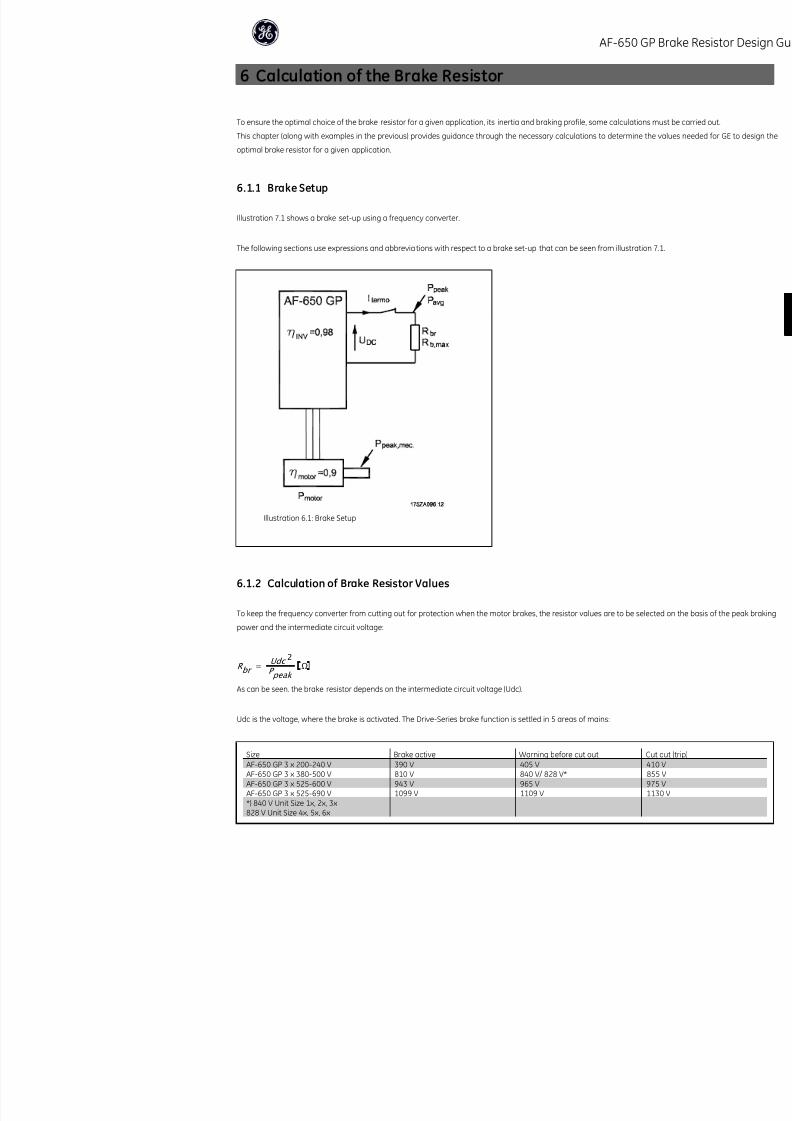
6.1.1 Brake Setup
Illustration 7.1 shows a brake set-up using a frequency converter.
The following sections use expressions and abbreviations with respect to a brake set-up that can be seen from illustrati
Illustration 6.1: Brake Setup
6.1.2 Calculation of Brake Resistor Values
To keep the frequency converter from cutting out for protection when the motor brakes, the resistor values are to be se
power and the intermediate circuit voltage:
R br =Udc 2
P peak
Ω
AF-650

8/20/2019 DET-700
http://slidepdf.com/reader/full/det-700 17/30
NB!
Check that the brake resistor can handle voltages of 410 V, 850 V, 975 V or 1130 V.
GE recommends the brake resistance Rrec, i.e. one that guarantees that thefrequency converter is able to brake at the highest braking torque (Mbr(%)) of
160%. The formula can be written as:
R rec Ω =
U dc 2 x 10
P motor x M br (%) x ηD
ηmotor is typically at 0.90 ηDRIVE is typically at 0.98
For 200 V, 480 V, 500 V and 600 V frequency converters, R rec at 160% braking torque is written as:
200V : R rec = 107780P motor Ω
480V : R rec =375300
P motor
Ω 1)
480V : R rec =428914
P motor
Ω 2)
500V : R rec =464923
P motor
Ω
600V : R
rec
=630137
P motor
Ω
690V : R rec =832664
P motor Ω
1) For frequency converters Unit Size 1x
2) For frequency converters Unit Size 2x + 3x
If a higher brake resistor resistanse is selected, 160% / 150% / 110% braking torque cannot be obtained, and there is a risk th
out for protection.
If braking is only e.g. at 80% torque, it is possible to install a smaller brake resistor, the size of which can be calculated using
NB!
The resistor brake resistance selected should not be higher than that recommended by GE. If a brake resistor with a higher
braking torque may not be achieved because there is a risk that the frequency converter cuts out for safety reasons.
NB!
If a short circuit in the brake transistor occurs, power dissipation in the brake resistor is only prevented by using a mains swi
mains for the frequency converter. (The contactor can be controlled by the frequency converter).
NB!
Do not touch the brake resistor as it can get very hot while/after braking. The brake resistor must be placed in a secure env
AF-650
6

8/20/2019 DET-700
http://slidepdf.com/reader/full/det-700 18/30
6.1.3 Calculation of Braking Power
When calculating the braking power, it is to be ensured that the brake resistor is able to handle the average power as we
is determined by the process period time, i.e. the length of the braking time in relation to the process period time. The p
torque, which means that as braking progresses, the brake resistor must be able to dissipate the energy input.
The illustration below shows the relation between the average power and the peak power.
Illustration 6.2: Relation between average power and the peak
power.
6.1.4 Calculation of the Brake Resistor Peak Power
Ppeak, mec is the peak power by which the motor brakes on the motor shaft. It is calculated as follows:
P peak , mec = P motor × M BR (%) W
Ppeak is the name used for the braking power dissipated to the brake resistor when the motor brakes.
Ppeak is lower than Ppeak,mec since the power is reduced by the efficiencies of the motor and the frequency converter.
The peak power is calculated as follows:
P peak = P motor × M BR (%) ×ηmotor × ηDRIVE W
AF-650

8/20/2019 DET-700
http://slidepdf.com/reader/full/det-700 19/30
6.1.5 Calculation of the Brake Resistor Average Power
The average power is determined by the process period time, i.e. the length of the braking time in relation to the process per
If the amount of kinetic energy (Eb) transferred to the resistor in each braking sequence (see examples 1 and 2 in the chapter
average power of the resistor can be calculated as follows:
P avg =
E b
T P W
Tp = period time in seconds.
If the amount of kinetic energy transferred to the resistor in each braking sequence is not known, the average power can be ca
period time and the braking time.
The duty-cycle for the braking sequence is calculated as follows:
Duty cycle =T b × 100
T P
%
Tp = process period time in seconds.
Tb = braking time in seconds.
GE offers brake resistors with a duty-cycle of max. 10% and 40%, respectively (some drives are only available with a duty-cyc
is applied, the brake resistors are able to absorb Ppeak for 10% of the period time. The remaining 90% of the period time wil
The average power with 10% duty-cycle can be calculated as follows: P avg = P peak × 10 % W
The average power with 40% duty-cycle can be calculated as follows: P avg = P peak × 40 % W
The calculations apply to intermittent braking using a period time of 120/300/600 seconds.
NB!
Longer time than the specified intermittent braking period time may result in overheating of the resistor.
AF-650
6

8/20/2019 DET-700
http://slidepdf.com/reader/full/det-700 20/30
6.1.6 Braking of Inertia
In the case of braking of high inertia values on the motor shaft, the brake resistor values can be based on the inertia, Δω
Δt is determined by the decel time.
NB!
The decel time goes from the rated motor frequency to 0 Hz.
Ppeak can be calculated as:
P peak = ηmotor × w
start × j ×Δw Δt
P peak
= ηmotor
× ηdrive
× ηstart
× j × ( 2 × π
60 )2 ×Δn Δt
j is the inertia of the motor shaft.
Calculate the value on the brake res istor as described under the preceding paragraphs.
AF-650

8/20/2019 DET-700
http://slidepdf.com/reader/full/det-700 21/30
AF-650
7

8/20/2019 DET-700
http://slidepdf.com/reader/full/det-700 22/30
7 Installation
7.1.1 Brake Cable
Max. length [m]: 20 m screened cable.
The connection cable to the brake resistor is to be screened/armoured. Connect the screen/armouring to the conductiv
and to the brake resistor metal cabinet by means of cable clamps.
NB!
Make sure that the brake resistors used are induction-free.
7.1.2 Protective Functions During Installation
When installing a brake resistor, every measure should be taken to avoid the risk of overloading, since a fire hazard may
heat resistor.
NB!
The brake resistor is to be fitted on a non-flammable material.
For protection of the installation, a thermal relay should be fitted that cuts off the frequency converter if the brake curre
Calculate the brake current setting of the thermal relay as follows:
Itherm relay = P brakeresistor max R brakeresistor
Rbr is the current brake resistor value calculated in the section on "Calculation of brake resistor values". Illustration 7.1 sh
AF-650

8/20/2019 DET-700
http://slidepdf.com/reader/full/det-700 23/30
Some of the GE Brake resistors contain a thermal switch. This switch is NC (normally closed) and can be used e.g. coasting sto
27. The drive will then coast, if the thermal switch is opened.
The thermal switch must comply with PELV.
The brake is protected against short-circuiting of the brake resistor, and the brake transistor is monitored to ensure that short-ci
A relay/digital output can be used for protecting the brake resistor against overloading in connection with a fault in the frequ
In addition, the brake makes it possible to read out the momentary power and the mean power for the latest 120 seconds. Th
energizing and make sure it does not exceed a limit selected in par. B-12 Brake Power Limit (kW). In par. B-13 Braking Therm
carry out when the power transmitted to the brake resistor exceeds the limit set in par. B-12 Brake Power Limit (kW).
NB!
Monitoring the brake power is not a safety function; a thermal switch is required for that purpose. The brake resistor circuit
Over voltage control (OVC) (exclusive brake resistor) can be selected as an alternative brake function in par. B-17 Over-voltag
all units. The function ensures that a trip can be avoided if the DC link voltage increases. This is done by increasing the output
the DC link. It is a very useful function, e.g. if the decel time is too short since tripping of the frequency converter is avoided
extended.
AF-650
7

8/20/2019 DET-700
http://slidepdf.com/reader/full/det-700 24/30
7.1.3 EMC Precautions
The following EMC precautions are recommended in order to achieve interference-free operation of the RS-485 networ
Relevant national and local regulations, for example regarding protective earth connection, must be observed. The RS-4
away from motor and brake resistor cables to avoid coupling of high frequency noise from one cable to another. Nor
sufficient, but keeping the greatest possible distance between the cables is generally recommended, especially where c
When crossing is unavoidable, the RS-485 cable must cross motor and brake resistor cables at an angle of 90 degrees.
7.1.4 Cable Connection
NB!
Cables General: All cabling must comply with national and local regulations on cable cross-sections and ambient tem
are recommended.
How to connect more than one resistor
Star parallel connection to ensure load is shared evenly between two or more
resistors.
R es is tor
AF-650
AF 650

8/20/2019 DET-700
http://slidepdf.com/reader/full/det-700 25/30
Flat Pack
To reduce the electrical noise from the wires between the brake resistor and the frequency converter, the wires must be twis
For enhanced EMC performance a metal screen can be used.
Wire Wound
Follow the instructions shown in the illustration below to ensure needed cooling of the resistor.
Mounting the resistor so the lamellas are horizontal will course overheating of the resistor.
AF-650
7
AF 650

8/20/2019 DET-700
http://slidepdf.com/reader/full/det-700 26/30
8 Programming
8.1.1 AF-650 GP Parameters
The following is a list of parameters for the DriveSeries which are important or relevant for braking with a Brake Resisto
Parameter Suggestion of settings
Par. B-00 DC Hold Current This parameter holds the motor function (holding torque) or pre-heats the
Par. B-01 DC Brake Current Depends on the desired braking torque
Par. B-02 DC Braking Time Set the desired DC braking time
Par. B-03 DC Brake Cut In Speed [RPM] Set the desired DC Brake Cut In SpeedPar. B-04 DC Brake Cut In Speed [Hz] Set the desired DC brake cut-in frequency
Table 8.1: DC Braking
Parameter Suggestion of settings
Par. B-10 Brake Function Resistor brake
Par. B-16 AC brake Max. Current Enter the maximum permissible current when using AC brake to avoid ov
brake function is available in Flux mode only (AF-650 GP only).
Table 8.2: AC Braking
Parameter Suggestion of settings
Par. B-10 Brake Function Resistor brake
Par. B-11 Brake Resistor (ohm) Depends on the unit, see the tables in chapter Brake Resistor Overview.
Par. B-12 Brake Power Limit (kW) Depends on the unit, see the tables in chapter Brake Resistor Overview.
Par. B-13 Braking Thermal Overload Warning or trip
Par. B-15 Brake Check Warning or trip
Par. B-17 Over-voltage Control Over-voltage control (OVC) reduces the risk of the drive tripping due to an
generative power from the load. - Must not be enabled in hoisting applica
Par. F-41 Torque Limiter (Braking) 160%
Par. E-51 Terminal 27 Mode Brake no warning
Brake ready no fault or
Brake fault
Par. E-52 Terminal 29 Mode Same as par. E-51 Terminal 27 Mode
Par. E-24 Output relay [21] Thermal warning The thermal warning turns on when t
the motor, the frequency converter, t[28] Brake, no brake warning Brake is active and there are no warn
[29] Brake ready, no fault Brake is ready for operation and ther
[30] Brake fault (IGBT) Output is Logic ‘1’ when the brake IGB
to protect the frequency converter if t
Use the output/relay to cut out the m
AF-650
AF-650

8/20/2019 DET-700
http://slidepdf.com/reader/full/det-700 27/30
AF-650
9
AF-650

8/20/2019 DET-700
http://slidepdf.com/reader/full/det-700 28/30
9 Alternative Braking Methods
9.1.1 DC Injection Braking
If the three-phase winding of the stator is fed with direct current, a stationary magnetic field Φ will be set up in the stat
in the bars of the cage rotor as long as the rotor is in motion. Since the electrical resistance of the rotor cage is very low,
a high rotor current. This current w ill produce a strong braking effect on the bars and hence on the rotor. As the speed fa
falls and with it the inductive impedance. The ohmic resistance of the rotor gradually becomes dominant and so increase
down. The braking torque generated falls away steeply just before standstill and finally ceases when there i s no further m
is therefore not suitable for actually holding a load at rest.
Drive-Series:
An over-modulated DC current added to the AC current works as an eddy current brake (par. B-02 DC Braking Time ≠ 0
9.1.2 AC-braking
When the motor acts as a brake the DC-link voltage will increase because energy is fed back to the DC-link. The principle in A
during the braking and thereby increase the thermal losses of the motor.
Drive-Series:
The brake energy is distributed in the motor by changing the loss conditions in the motor. The AC brake function cannot
frequency since this will overheat the motor (par. B-10 Brake Function = [2]). Using factory settings it is possible to brake
2/3 of rated speed and with about 25 % at rated speed. The function is not working at low speed (below 1/3 of nominal
9.1.3 Mechanical Holding Brake
A mechanical holding brake mounted directly on the motor shaft normally performs static braking. In some application
static holding of the motor shaft (usually synchronous permanent motors). A holding brake is either controlled by a PLC
frequency converter (relay or solid state).
NB!
When the holding brake is included in a safety chain:
A frequency converter cannot provide a safe control of a mechanical brake. A redundancy circuitry for the brake control m
AF 650
AF-650

8/20/2019 DET-700
http://slidepdf.com/reader/full/det-700 29/30
9.1.4 Optimum Braking
Dynamic braking is useful from max. speed down to a certain frequency. Below this frequency DC braking is to be applied as
doing this is to use a combination of dynamic and DC braking. See illustration 11.1. The parameters can be found further o
Programming.
For further information about DC Braking see section 11.1.1.
Illustration 9.1:
NB!
When changing from dynamic to DC braking, there will be a short period (2-6 milliseconds) with very low braking torque.
How to calculate optimum DC-brake cut in frequency:
Slip S =n O − n n
n O × 100 %
Synchronous speed n 0 =
f × 60
p [1/min]
f = frequency
p = no. of pole pairs
nn = speed of the rotor
DC-brake cut in frequency = 2 ×S × f
100 Hz
AF 650
9

8/20/2019 DET-700
http://slidepdf.com/reader/full/det-700 30/30
The instructions do not purport to cover all details or variations in equipment nor to provide for every possible
contingency to be met in connection with installation, operation or maintenance. Should further information be
desired or should particular problems arise which are not covered sufficiently for the purchaser’s purposes, the
matter should be referred to the GE company.
AF-650 GP is a trademark of the General Electric Company.
GE Consumer & Industrial
41 Woodford Avenue
Plainville, CT 06062
www.geelectrical.com/drives
130R0373 MG90T102 *MG90T102*DET-700
Related Documents