STEP 2: ATTACH ARM TO MOUNTING POST STEP 4: ATTACH MONITOR TO MONITOR ARM STEP 3: ATTACH VESA BRACKET TO MONITOR FRICTION ADJUSTMENTS CABLE MANAGEMENT Top Mount Arm Align groove in Top Mount Arm stem with screw on Mounting Post. Slide stem into Mounting Post (b) and secure with screw (a). Bracket Mount Arm Slide bracket onto Mounting Post (c). Tighten lever (d) to secure at desired height. 1. Slide VESA Bracket over Lip at end of Arm (a). 2a. If the arm is equipped with a Quick-Release Lever (b), push bottom of monitor into Arm until you hear a click. To remove, depress Quick Release Lever and remove monitor from Arm. 2b. If the Arm is not equipped with a Quick Release Lever, secure monitor to Arm using two screws (c) as shown. Ball Joint Friction Heavy monitors, or monitors mounted to an arm for a prolonged period of time may require increased friction. This can be achieved by tightening the three Ball Joint Friction Screws (a). Mounting Post Friction To increase friction on a height- adjustable post, or secure the post at a particular height, turn the Friction Dial (b) clockwise until the desired level of friction is achieved. To decrease friction for easier height adjustability, turn the Friction Dial counter clockwise. 1. Select 75mm or 100mm VESA Bracket to match hole pattern on back of monitor. 2. Place VESA Bracket (b) in position on back of monitor with cut-out toward top of monitor (a) and attach using the four screws provided, or the screws that came with the monitor. b. c. a. b. a. a. b. increase friction decrease friction M7 Desk Mount Installation Instructions PN R1900455000NL00 Rev. 9/11/08 b. c. d. a. a. b. 1. Slide cable management access panels forward to release and remove them (a). 2. Route cable(s) through the open channels in the underside of the monitor arm links. 3. Reposition access panels and slide back to secure (b).

Welcome message from author
This document is posted to help you gain knowledge. Please leave a comment to let me know what you think about it! Share it to your friends and learn new things together.
Transcript
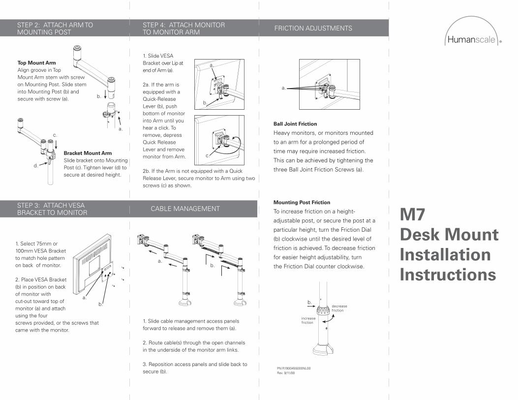
STEP 2: ATTACH ARM TO MOUNTING POST
STEP 4: ATTACH MONITORTO MONITOR ARM
STEP 3: ATTACH VESABRACKET TO MONITOR
FRICTION ADJUSTMENTS
CABLE MANAGEMENT
Top Mount ArmAlign groove in TopMount Arm stem with screwon Mounting Post. Slide steminto Mounting Post (b) andsecure with screw (a).
Bracket Mount ArmSlide bracket onto Mounting Post (c). Tighten lever (d) to secure at desired height.
1. Slide VESA Bracket over Lip at end of Arm (a).
2a. If the arm is equipped with a Quick-Release Lever (b), push bottom of monitor into Arm until you hear a click. To remove, depress Quick Release Lever and remove monitor from Arm.
2b. If the Arm is not equipped with a Quick Release Lever, secure monitor to Arm using two screws (c) as shown.
Ball Joint Friction
Heavy monitors, or monitors mounted
to an arm for a prolonged period of
time may require increased friction.
This can be achieved by tightening the
three Ball Joint Friction Screws (a).
Mounting Post Friction
To increase friction on a height-
adjustable post, or secure the post at a
particular height, turn the Friction Dial
(b) clockwise until the desired level of
friction is achieved. To decrease friction
for easier height adjustability, turn
the Friction Dial counter clockwise.
1. Select 75mm or 100mm VESA Bracket to match hole pattern on back of monitor.
2. Place VESA Bracket (b) in position on back of monitor with cut-out toward top of monitor (a) and attach using the fourscrews provided, or the screws that came with the monitor.
b.
c.
a.b.
a.
a.
b.
increasefriction
decreasefriction
M7Desk MountInstallationInstructions
PN R1900455000NL00Rev. 9/11/08
b.
c.
d.
a.
a.
b.
1. Slide cable management access panels forward to release and remove them (a).
2. Route cable(s) through the open channels in the underside of the monitor arm links.
3. Reposition access panels and slide back to secure (b).

a.a.
b.c.
e.
f.
d.
g.
c.
b.
a.
b.
d.
C.
d.
Clamp Mount
1. Remove Bottom Assembly
from Base by loosening
screws (a) with hex key.
2. Place Vertical Assembly
on Base (b). Make sure the
External Tube is loosely
secured by lining up cut-out
with guide inside Base (c).
3. Use M12 screw and hex
key to secure the Vertical
Assembly to the Base (d).
Make sure the screw face is
flush with the underside of
the Base.
4. Position Base at desk
edge (e).
5. From under desk,
reattach Bottom
Assembly (f). Tighten
Screws (a) and Clamp Disk
Screws (g) to secure.
Proceed to "Step 2: AttachArm to Mounting Post"
Low Profile Mount
Follow steps 2-3 for Clamp
Mount. Note: Low Profile
Mount cannot be
disassembled.
2. Slide base onto
mounting edge (a).
Tighten Clamping Screws
(b) with hex key.
Proceed to "Step 2: AttachArm to Mounting Post"
Direct Mount
1. Position unit in desired
location on work surface.
2. Secure using four screws
and washers as shown.
Proceed to "Step 2: AttachArm to Mounting Post”
Grommet Mount
1. Separate the grommet
mount assembly (bracket,
mounting screws and
backing plate) from the M7
pole assembly (a) by
loosening the two pinch
screws (b) and sliding it off
the end of the pole. Leave
the plastic cover on the pole.
Grommet Mount (continued)
2. Remove lower plate (c)
from grommet assembly by
removing the three
mounting screws (d).
Remove backing from
adhesive tape and place
lower plate on underside of
work surface, concentric
with grommet hole.
3. Position upper mount into
grommet hole.
4. Determine which three of
the four available mounting
holes are needed for the
specific grommet hole.
Determine by using the hole
style indicator (e) which is
next to each hole.
• Small circles for small
circular grommet holes.
From 2.5” - 2.75”
• Large circles for large
circular grommet holes.
From 2.75” - 3.125”
• Squares for rectangular
2 x 4 style grommet holes
5. Align three mounting
screws with holes in lower
plate. Snug three screws to
table (f) but do not tighten.
Grommet Mount (continued)
6. Insert vertical assembly
(pole) into mount and tighten
pinch screws (b) with pole at
desired height.
7. Fully tighten three screws
(d) that hold base to desk.
8. Lower plastic cover (g)
down to cover upper mount.
Proceed to “Step 2: Attach
Arm to Mounting Post”
Bolt Mount
1. Drill 1/2" hole through
desk in desired location.
2. Apply protective foam
sheet to bottom of base if
desired.
3. Pass large bolt (a) through
hole in curved plate (b).
Make sure to note the
direction of the curve. Pass
bolt through hole in desk
and screw into vertical
assembly (pole).
4. Verify that the small hole
(c) at the top of the pole is
facing away from the user
and then tighten large bolt
(a) with the provided wrench.
e.
f.
g.a.
b.
b.
a.
STEP 1: IDENTIFY YOUR BASE MOUNT AND FOLLOW CORRESPONDING INSTRUCTIONS.
Proceed to "Step 2: Attach Arm to Mounting Post"
Related Documents


![SUD- Instructions: STEP 1. KBTRAY- STEP 2: s STEP 3: Set ... · STEP 2: s STEP 3: Set shelf to desk. Hand tighten clamps to desk. [68.4mm] 2.69in On under side of tray, attach L-Brackets](https://static.cupdf.com/doc/110x72/5ed655237998195daf29d839/sud-instructions-step-1-kbtray-step-2-s-step-3-set-step-2-s-step-3-set.jpg)
