Designing with Geosynthetics Fifth Edition Robert M. Koerner Director, Geosynthetic Institute Emeritus Professor of Drexel University Upper Saddle River, New Jersey 07458 TJ FA 440 PAGE 001

Welcome message from author
This document is posted to help you gain knowledge. Please leave a comment to let me know what you think about it! Share it to your friends and learn new things together.
Transcript
Designing withGeosyntheticsFifth Edition
Robert M. KoernerDirector, Geosynthetic InstituteEmeritus Professor of Drexel University
Upper Saddle River, New Jersey 07458
TJ FA 440PAGE 001
Contents
PREFACE xvii
OVERVIEW OF GEOSYNTHETICS 1
1.0 Introduction 21.1 Basic Description of Geosynthetics 3
Types of Geosynthetics 5Organization by Function 8Market Activity 8
1.2 Polymeric Materials 9
1.2.11.2.21.2.3
Brief Overview 10Polymer Identification 15Polymer Formulations 27
1.3 Overview of Geotextiles 29
History 29Manufacture 30Current Uses 38Sales 40
TJ FA 440PAGE 002
vi
1.4 Overview of Geogrids 41
History 41Manufacture 42Current Uses 43Sales 44
1.5 Overview of Geonets 44
History 44Manufacture 45Current Uses 47Sales 47
1.6 Overview of Geomembranes 48
History 48Manufacture 49Current Uses 56Sales 58
1.7 Overview of Geosynthetic Clay Liners 59
History 59Manufacture 59Current Uses 61Sales 62
1.8 Overview of Geopipe (aka Plastic Pipe) 62
History 62Manufacture 63Current Uses 64Sales 65
1.9 Overview of Geofoam 66
History 66Manufacture 66Current Uses 68Sales 68
Contents
TJ FA 440PAGE 003
Contents Contents
1.10 Overview of Geocomposites 69
Geotextile-Geonet Composites 69Geotextile-Geomembrane Composites 69Geomembrane-Geogrid Composites 69Geotextile-Geogrid Composites 70Geotextile-Polymer Core Composites 70Geosynthetic-Soil Composites 70Other Geocomposites 72
1.11 Outline of Book 72References 73Problems 74
vii
2 DESIGNING WITH GEOTEXTILES 79
2.0 Introduction 812.1 Design Methods 81
2.1.12.1.22.1.3
Design by Cost and Availability 82Design by Specification 82Design by Function 92
2.2 Geotextile Functions and Mechanisms 93
Separation 93Reinforcement 94Filtration 98Drainage 103Containment 105Combined Functions 105
2.3 Geotextile Properties and Test Methods 106
2.3.12.3.22.3.32.3.42.3.52.3.62.3.7
General Comments 106Physical Properties 107Mechanical Properties 108Hydraulic Properties 128Endurance Properties 140Degradation Considerations 152Summary 161
TJ FA 440PAGE 004
!I
viii
2.4 Allowable Versus Ultimate Geotextile Properties 162
2.4.1 Strength-Related Problems 1622.4.2 Flow-Related Problems 165
2.5 Designing for Separation 166
2.5.1 Overview of Applications166
2.5.2 Burst Resistance 1662.5.3 Tensile Strength 1682.5.4 Puncture Resistance ~1712.5.5 Impact (Tear) Resistance 1732.5.6 Summary 176
2.6 Designing for Roadway Reinforcement 177
2.6.1 Unpaved Roads 1772.6.2 Membrane-Encapsulated Soils 1882.6.3 Paved Roads 196
2.7 Designing for Soil Reinforcement 197
2.7.12.7.22.7.32.7.4
2.7.5
Geotextile Reinforced Walls 197Geotextile Reinforced Embankments 216Geotextile Reinforced Foundation Soils 226Geotextiles for Improved Bearing Capacityand Basal Reinforcement 235Geotextiles for In Situ Slope Stabilization 239
2.8 Designing for Filtration 246
Overview of Applications 246General Behavior 246Geotextiles Behind Retaining Walls 247Geotextiles Around Underdrains 251Geotextiles Beneath Erosion-Control StructuresGeotextiles Silt Fences 257Summary 263
2.9 Designing for Drainage 263
Overview of Applications 263General Behavior 264Gravity Drainage Design 265
254
Contents
TJ FA 440PAGE 005
Contents Contents
2.10
Pressure Drainage Design 269Capillary Migration Breaks 270Summary 272
Designing for Multiple Functions 273
Logic for Chapter 273Reflection Crack Prevention in Pavement OverlaysRailroad Applications 285Flexible Forming Systems 288
273
2.11 Construction Methods and Techniques Using Geotextiles 304
Introduction 304Geotextile Installation Survivability 304Cost and Availability Considerations 306Summary 306
References 307Problems 314
3 DESIGNING WITH GEOGRIDS 328
3.0 Introduction 3283.1 Geogrid Properties and Test Methods 331
Physical Properties 331Mechanical Properties 332Endurance Properties 343Degradation Issues 344Allowable Strength Considerations347
3.2 Designing for Geogrid Reinforcement 349
Paved Roads--Base Courses 349Paved Roads--Pavements 351Unpaved Roads 354Embankments and Slopes 356Reinforced Walls 362Foundation and Basal ReinforcementVeneer Cover Soils 380
374
ix
TJ FA 440PAGE 006
x
3.3 Design Critique 3873.4 Construction Methods 388References 389Problems 392
396
4.0 Introduction 3964.1 Geonet Properties and Test Methods 397
Physical Properties 397Mechanical Properties 400Hydraulic Properties 403Endurance Properties 408Environmental Properties 411Allowable Flow Rate 412
4.2 Designing for Geonet Drainage 415
Theoretical Concepts 415Environmental-Related Applications 416Transportation-Related Applications 420
Contents
4.3 Design Critique 4234.4 Construction Methods 424References 425Problems 426
428
5.0 Introduction 4305.1 Geomembrane Properties and Test Methods
Overview 431Physical Properties 432Mechanical Properties 439Endurance Properties 458Liletime Prediction 467Summary 474
431
TJ FA 440PAGE 007
Contents Contents
5.2 Survivability Requirements 4745.3 Liquid Containment (Pond) Liners 476
Geometric Considerations 476Typical Cross Sections 478Geomembrane Material Selection 482Thickness Considerations 483Side-Slope Considerations 487Runout and Anchor Trench Design 500Summary 506
5.4 Covers for Reservoirs and Quasi-Solids 506
Overview 507Fixed Covers 507Floating Covers 509Quasi-Solid Covers 515Complete Encapsulation515
5.5 Water Conveyance (Canal) Liners 517
Overview 517Basic ConsiderationsUnique Features 521Summary 525
517
5.6 Solid-Material (Landfill) Liners 525
5.6.1 Overview 5275.6.2 Siting Considerations and Geometry 5315.6.3 Typical Cross Sections 5325.6.4 Grading and Leachate Removal 5395.6.5 Material Selection 5455.6.6 Thickness 5465.6.7 Puncture Protection 5475.6.8 Runout and Anchor Trenches 5495.6.9 Side Slope Subgrade Soil Stability 5505.6.10 Multitined Side Slope Cover Soil Stability5.6.11 Access Ramps 5545.6.12 Stability of Solid-Waste Masses 5545.6.13 Vertical Expansion (Piggyback) Landfills5.6.14 Heap Leach Pads 5595.6.15 Solar Ponds 5595.6.16 Summary 560
550
558
xi
TJ FA 440PAGE 008
xii
5.7 Landfill Covers and Closures 563
Overview 563Various Cross Sections 564Gas Collection Layer 566Barrier Layer 568Infiltrating Water Drainage Layer 570Protection (Cover Soil) Layer 571Surface (Top Soil) Layer 571Post-Closure Beneficial Uses and Aesthetics
5.8 Wet (Bioreactor) Landfills 573
5.8.1 Background 5745.8.2 Base Liner Systems 5755.8.3 Leachate Collection System 5755.8.4 Leachate Removal System 5775.8.5 Filter and/or Operations Layer 5775.8.6 Daily Cover Materials 5775.8.7 Final Cover Issues 5775.8.8 Waste Stability Concerns 5785.8.9 Summary 579
5.9 Underground Storage Tanks 579
Overview 579Low-Volume Systems 579High-Volume Systems 581Tank Farms 581
5.10 Hydraulic and Geotechnical Applications 581
Earth and Earth/Rock Dams 581Concrete and Masonry Dams 583Roller-Compacted Concrete DamsGeomembrane Dams 585Tunnels 585Vertical Cutolf Walls 585
583
5.11 Geomembrane Seams 587
Seaming Methods 589Destructive Seam Tests 593Nondestructive Seam TestsSummary 599
596
572
Contents
TJ FA 440PAGE 009
ontents Contents
5.12 Details and Miscellaneous Items 602
Connections 602Appurtenances 602Leak Location (After Waste Placement) TechniquesWind Uplift 607Quality Control and Quality Assurance 608
5.13 Concluding Remarks 611References 612Problems 618
6 GEOSYNTHETIC CLAY LINERS 630
6.0 Introduction 6306.1 GCL Properties and Test Methods 634
Physical Properties 634Hydraulic Properties 636Mechanical Properties 642Endurance Properties 647
6.2 Equivalency Issues 6495.3 Designing with GCLs 652
GCLs as Single Liners 652GCLs as Composite LinersGCLs as Composite CoversGCLs on Slopes 659
654657
6.4 Design Critique 6616.5 Construction MethodsReferences 665Problems 667
663
DESIGNING WITH GEOPIPES 669
7.0 Introduction 670Geopipe Properties and Test Methods
7.1.1 Physical Properties 6727.1.2 Mechanical Properties 675
672
606
xiii
TJ FA 440PAGE 010
xiv
Chemical Properties 684Biological Properties 685Thermal Properties 686Geopipe Specifications 686
Contents
7.2 Theoretical Concepts 689
7.2.1 Hydraulic Issues 6897.2.2 Deflection Issues 694
Design Applications 698
7.3.17.3.2
7.3.3
Pavement Underdrains---Perforated Profiled Collection PipesPrimary Leachate Collection Systems-Perforated ProfiledCollection Pipes 702Liquid Transmission--Solid-Wall Nonperforated Pipewith Deflection Calculations 704
699
7.4 Design Critique 7057.5 Construction Methods 706
Subgrade Preparation 707Connections 709Placement 711Backfilling Operations 711
References 712Problems 713
8 DESIGNING WITH GEOFOAM 715
8.0 Introduction 7158.1 Geofoam Properties and Test Methods
Physical Properties 716Mechanical Properties 719Thermal Properties 722Endurance Properties 723
8.2 Design Applications 724
8.2.1 Lightweight Fill 7248.2.2 Compressible Inclusion726
716
TJ FA 440PAGE 011
~ Pipesiled
Contents
699
Contents
8.2.3 Thermal Insulation 7298.2.4 Drainage Applications 731
8.3 Design Critique 7328.4 Construction MethodsReferences 734Problems 735
733
9 DESIGNING WITH GEOCOMPOSITES 736
9.0 Introduction 7379.1 Geocomposites in Separation 737
9.1.19.1.2
9.1.3
9.1.49.1.5
Temporary Erosion and Revegetation MaterialsPermanent Erosion and Revegetation Materials--Biotechnical-Related 741Permanent Erosion and Revegetation Materials--Hard Armor-Related 741Design Considerations 742Summary 747
9.2 Geocomposites in Reinforcement 747
9.2.19.2.29.2.39.2.49.2.5
Reinforced Geotextile Composites 747Reinforced Geomembrane CompositesReinforced Soil Composites 749Reinforced Concrete Composites 755Reinforced Bitumen Composites 755
749
9.3 Geocomposites in Filtration 7569.4 Geocomposites in Drainage 757
Wick (Prefabricated Vertical) Drains 758Sheet Drains 769Highway Edge Drains 776
740
xv
9.5 Geocomposites in Containment (Liquid/Vapor Barriers}9.6 Conclusion 782References 782Problems 784
779
INDEX 788
TJ FA 440PAGE 012
374 Designing with Geogrids Ch;
If fines (silts and/or days) are allowed for the reinforced zone backfill soilpossible water in front, behind, and beneath the reinforced zone must belected, transmitted, and discharged. Proper drainage control is absolutely critical inregard. Furthermore, the top of the zone should be waterproofed--for example,geomembrane or a geosynthetic clay liner--to prevent water from entering thezone from the surface. Surface water drainage as well as drainage from theearth zone is obviously of concern with respect to potential buildup of pore watersures behind or within the reinforced soil zone. (See Koerner and Soong [46] fordrainage system designs in this regard.)
In closing this section on geogrid reinforced walls, the current tendency tolive (or evergreen) walls with open facing should be mentioned. As we sawFigure 3.14, the sequence is a steel wire mesh (alternatively a gabion), backed by arectional geogrid and then by a geosynthetic erosion control material. Thegeogrids (always unidirectional types) are either attached to the steel wire meshor they are frictionally connected by sufficient overlap length. Such walls avoid mablock durability concerns and offer a considerably less expensive wall system. Of,the durability of the steel wire and bidirectional geogrid backup must be consideredthis is a viable research topic when considering 100-year permanent wall lifetimes.
3.2.6 Foundation and Basal Reinforcement
Geogrids have been used to increase bearing capacity of poor foundation soilsferent ways: as a continuous layer, as multiple closely spaced continuousgranular soil between layers, and as mattresses consisting of three-dimensionalconnected cells. The technical database for the single-layer continuous sheereported by Jarrett [47] and by Milligan and Love [48]; in both cases large-scaleratory tests are used. Figure 3.19 presents some of Milligan and Love’s workin the conventional nondimensionalized q/Cu versus 9/B manner and also as q/~sus p/B where q is the bearing capacity and p is the settlement. The latter graphconventional but does sort out the data nicely. Clearly shown in both instancesmarked improvement in load-carrying capacity using geogridsonly a nominal beneficial effect at low deformation. Beyond these observations, acise design formulation is not currently available.
Instead of focusing on a global increase in bearing capacity, it is quitesingle or multiple layers of geogrid (or geotextile) will aid in minimizing ordifferential settlement. Here localized settlements due to abruptly settlingweak zones can be spanned by the layer of reinforcement. This is known asimprovement (rather than bearing capacity via base reinforcement):gard is a technique called piggybacking--the construction of new landfills aboveing landfills: The approach is to use arching theory in the calculation of thestress arising from localized Subsidence (i.el, differential settlement)Suitably strong reinforcement.
It should be recognized that arching in natural soils overlying a locallyfoundation is well established. In the 1930s, both Karl Terzaghi in Austria
TJ FA 440PAGE 013
554 Designing with Geomembranes Chap. 5
b - ~- 4acFS= 2a
13.8 + ~(13.8)2 - 4(6.11(2.22)2(6.1)
FS = 2.10
While the value appears to be acceptable, it is nevertheless disconcerting that the liner sys-tem per se is being used as the veneer reinforcement mechanism. Had higher reductionfactors been used. the resulting FS value would be proportionately decreased. That said,when the solid waste is placed against the leachate collection soil, a resisting berm is creat-ed. bringing stability to the situation at that time.
5.6.11 Access Ramps
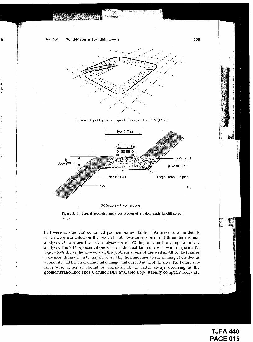
For below-grade landfills it is necessary to grade the subgrade to accommodate thenecessary access ramp(s), line the entire facility, and then construct a road above theliner cross section. A typical geometry is shown in Figure 5.46a. A particularly trouble-some aspect of this design is that the road must be built above the completed liner sys-tem. A variety of problems have occurred in the past:
¯ Inadequate drainage where the ramp meets the upper slope, with subsequenterosion and scour of the roadway itself.
¯ Inadequate roadway material above the liner system, with ramp soil sliding offthe upper geomembrane due to truck traffic.
¯ Inadequate roadway thickness above the liner system, with the upper geomem-brahe failing in tension along the slope due to truck traffic.
¯ Inadequate roadway thickness above the liner system, with an underlying hydrat-ed GCL creating slippage of the overlying geomembrane, and entire roadway.
Clearly, a conservative design is required: Figure 5.46b presents some recommenda-tions. While a 600 to 900 mm thickness might seen excessive, the dynamic stressescaused by braking trucks are high, and furthermore, the ramp soil can be removed inwhole or in part as the waste elevation rises during filling operations.
5.6.12 Stability of Solid-Waste Masses
Upon first consideration, the stability of solid waste failing within itself should presentno particular concern since its shear strength characteristics should be quite high.Singh and Murphy [83] present shear strength parameters of solid waste transitioningfrom high in friction (24 to 36°) to being high in cohesion (80 to 120 kPa). Obviously,the aging of the waste is an issue, but at all times the shear strength is quite high. Awidely used MSW shear strength evelope assembled by Kavazanjian [84] indicates abilinear response of 33° friction transitioning at less than 30 kPa normal stress to acohesion of 24 kPa.
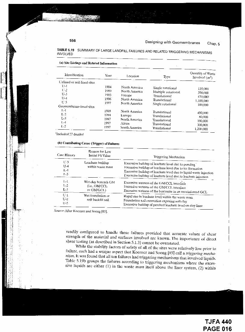
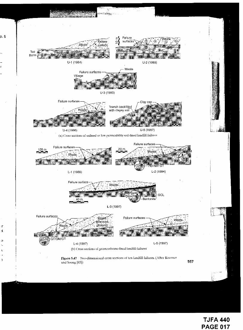
Paradoxically, there have been some massive failures of solid waste. Koerner andSoong [85] report on ten such failures of which half were unlined or soil-lined sites, and
TJ FA 440PAGE 014
e
e
Sec. 5.6 Solid-Material (Landfill) Liners
{a) Geometry of typical ramp-grades from gentle to 25 % (14.0°)
typ. 5-7 m
typ.600-900 mm
(W-Mr) GTCrushed stone
(SW-GW~(NW-NP) GT
(NW-NP) GT Large stone and pipe
GM
555
(b) Suggested cross section
Figure 5.46 Typical geometry and cross section of a below-grade landfill accessramp.
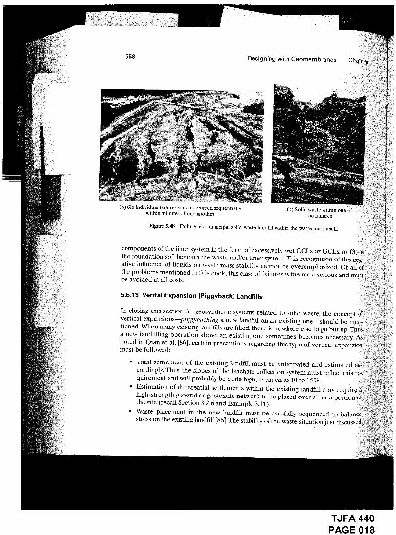
half were at sites that contained geomembranes. Table 5.19a presents some detailswhich were evaluated on the basis of both two-dimensional and three-dimensionalanalyses. On average the 3-D analyses were 16% higher than the comparable 2-Danalyses. The 2-D representations of the individual failures are shown in Figure 5.47.Figure 5.48 shows the enormity of the problem at one of these sites. All of the failureswere most dramatic and many involved litigation and fines, to say nothing of the deathsat one site and the environmental damage that ensued at all of the sites. The failure sur-faces were either rotational or translational, the latter always occurring at thegeomembrane-lined sites. Commercially available slope stability computer codes are
TJ FA 440PAGE 015
556
TABLE 5,19INVOLVED
Designing with Geomembranes Chap. 5
SUMMARY OF LARGE LANDFILL FAILURES AND RELATED TRIGGERING MECHANISMS
(a) Site Listings and Related Information
Quantity of WasteIdentification Year Location Type Involved (m3)
Unlined or soil-lined sitesU-1 1984 North AmericaU-2 1989 North AmericaU-3 1993 EuropeU-4 1996 North AmericaU-5 1997 North America
Geomembrane-lined sitesL-1 1988 North AmericaL-2 1994 EuropeL-3 1997 North AmericaL-4 1997 AfricaL-5 1997 South America
1Included 27 deaths!
Single rotational 110,000Multiple rotational 500,000Translational 470,0001Translational 1,100,000Single rotational 100,000
Translational 490,000Translational 60,000Translational I00,000Translational 300,000Translational 1,200,000
(b) Contributing Cause (Trigger) of Failures
Reason for LowCase History Initial FS Value
U-3 Leachate buildupU-4 within waste massL-4L-5
L-1 Wet clay beneath GML-2 fi.e.. GM/CCLL-3 or GM/GCL ~
U-1 Wet foundation orU-2 soft backfill soilU-5
Source: After Koerner and Soong [85].
Triggering Mechanism
Excessive buildup of leachate level due to pondingExcessive buildup of leachate level due to ice formationExcessive buildup of leachate level due to liquid waste iniectionExcessive buildup of leachate level due to leachate injection
Excessive wetness of the GM/CCL interf~�~Excessive wetness of the GM/CCL interfaceExcessive wetness of the bentonite in aii unreinforced GCL
Rapid rise in leachate level within the waste massFoundation soil excavation exposing soft clayExcessive buildup of perched leachate level on clay liner
readily configured to handle these failures provided that accurate values of shearstrength of the material and surfaces involved are known. The importance of directshear testing (as described in Section 5.1.3) cannot be overstated.
While the stability factors of safety of all of the sites were relatively low prior tofailure, each had a unique aspect that Koerner and Soong [85] call a triggering mecha-nism. It was found that all ten failures had triggering mechanisms that involved liquids.Table 5.19b groups the failures according to triggering mechanisms where the exces-sive liquids are either (1) in the waste mass itself above the liner system, (2) within
TJ FA 440PAGE 016
ToeBerm-
U-1 (1984)
FailureVillage
U-3 (1993)
U-2 (1989)
Waste
Trench backfilledwith clayey soil
U-5 (1997)(a) Cross sections of unlined or low permeability soil-lined landfill failures
Failure100 m 20 m
Failure surfaces
L-1 (1988)
Failt
40m
L-3 (1997)
L-2 (1994)
GCL
Failure
GT/GM/GTL-4 (1997)
(b) Cross sections of geomembrane-lined landfill failures
L-5 (1997)
Figure 5.47 T~vo-dimensional cross sections of ten landfill failures. (After Koernerand Soong [851) 557
TJ FA 440PAGE 017
558
(a) Six individual failures which occurred sequentiallywithin minutes of one another
Designing with Geomembranes
Figurc 5.48
(b) Solid waste within one ofthe failures
Failure of a municipal solid-waste landfill within the waste mass itself.
components of the liner system in the form of excessively wet CCLs or GCLs, or (3) inthe foundation soil beneath the waste and/or liner system. This recognition of the neg-ative influence of liquids on waste mass stability cannot be overemphasized. Of allthe problems mentioned in this book, this class of failures is the most serious and mustbe avoided at all costs.
5.6.13 Verital Expansion (Piggyback) Landfills
In closing this section on geosynthetic systems related to solid waste, the concept ofvertical expansions--piggybacking a new landfill on an existing one should be men-tioned. When many existing landfills are filled, there is nowhere else to go but up. Thusa new landfilling operation above an existing one sometimes becomes necessary. Asnoted in Qian et al. [86], certain precautions regarding this type of vertical expansion-must be followed:
Total settlement of the existing landfill must be anticipated and estimated a¢;~cordingly. Thus, the slopes of the leachate collection system must reflect this re-quirement and will probably be quite high, as much as 10 to 15%.Estimation of differential settlements within the existing landfill may require ahigh-strength geogrid or geotextile network to be placed over all or athe site (recall Section 3.2.6 and Example 3.11).Waste placement in the new landfill must be carefully sequenced tostress on the existing landfill [86]. The stability of the waste situation just discussed;
TJ FA 440PAGE 018
tn one of :
’Ls, ort of the ne~.d. Of all ofus and must
concept ofald be men,
ecessary.d exl:
;timatedflect this re,
ag
Sec. 5.6 Solid-Material (Landfill) Liners559
is exacerbated greatly by the addition of a large surcharge stress, which is whatthe piggybacked landfill represents to the underlying waste¯
¯ Methane gas (if generated) migrating from the existing landfill must be carriedlaterally under the new landfill liner to side-slope venting and/or collection loca-tions. Active gas collection systems may be required.
¯ Leachate collection from the existing landfill should be considered¯ If required,directionally drilled withdrawal wells at the perimeter of the facility may be aconsideration¯
¯ Access to the site via haul roads must be carefully considered so that there willbe no damage to, or instability of, the underlying liner system¯
5.6.14 Heap Leach Pads
Heap leach pads consist of a geomembrane with an overlying drainage system, andthen a precious metal (gold, silver, or copper) bearing ore heaped above. A cyanide orsulfuric acid solution is sprayed on top of the ore, leaches through it reacting with themetals, and carries the solution to the drainage system where it is collected. Beneaththe drainage system is a geomembrane barrier, hence the topic is included at this loca-tion. Separation of the ore from the leachate occurs in an on-site processing plant. Theleaching solution is renewed and the process is repeated until it is no longer economi-cal. Figure 5.49a illustrates the general configuration.
The heap itself is often enormous in its proportions (see Figure 5.49b). Ores of22 kN/m3 unit weight at heights up to 150 m produce enormous stresses on the drainagesystem and geomembrane. The concept is used widely in the western United States andCanada and in many South American countries (see Smith and Welkner [88]).
Regarding the design of the geomembrane, its thickness and type is very subjec-tive and all resin types have been used to varying degrees. The drainage system iscoarse gravel along with an embedded pipe system allowing for rapid and efficient re-moval of the ore-bearing solution from beneath the heap. This situation requires con-sideration of a sand cushion layer or a very thick protection geotextile between thegeomembrane and drainage/collection gravel. The design method presented in Section5.6.7 should be considered, with the reminder that it is developed on the basis that dif-ferent geomembrane thicknesses and types will behave differently. Thiel and Smith[89] have summarized the key geotechnical concerns with respect to heap leach padsand related issues (see Table 5.20).
5.6.15 Solar Ponds
There are a number of solid material liner systems that have not yet been mentioned.A small but growing segment of (hese systems is solar ponds [90]. Here the geomem-brane is placed in an excavation and then it is filled with salt. Solar energy is collectedand stored as heat. A salt gradient effect is created, whereby zones are set up constant-ly replenishing new heat as it is gradually withdrawn from the lower storage zone foruseful purposes. The main consideration insofar as the geomembrane is concerned is
TJ FA 440PAGE 019
Sec. 5.7 Landfill Covers and Closures
Time (days)1 10 100
01,000 10,000
565
-5
-10
-15
-20
-25
-30
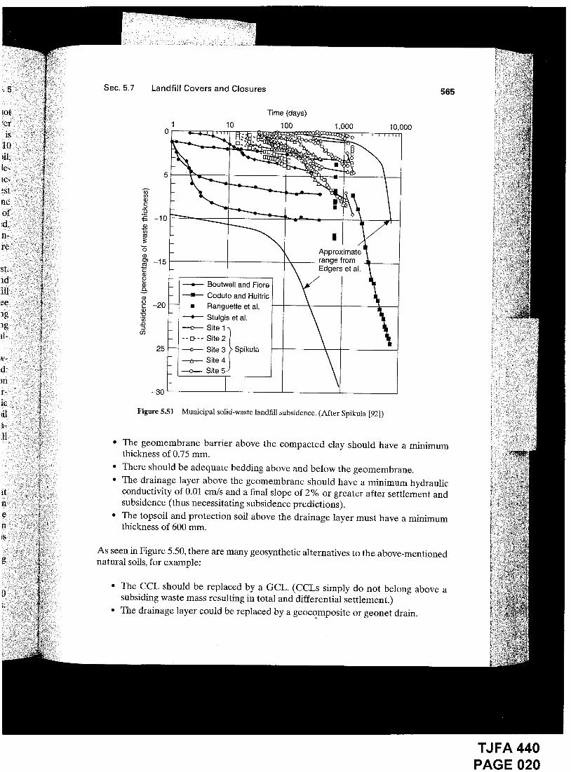
Figure 5.51 Municipal solid-waste landfill subsidence. (After Spikula [92])
The geomembrane barrier above the compacted clay should have a minimumthickness of 0.75 mm.
¯ There should be adequate bedding above and below the geomembrane.¯ The drainage layer above the geomembrane should have a minimum hydraulic
conductivity of 0.01 cm/s and a final slope of 2% or greater after settlement andsubsidence (thus necessitating subsidence predictions).
¯ The topsoil and protection soil above the drainage layer must have a minimumthickness of 600 ram.
As seen in Figure 5.50, there are many geosynthetic alternatives to the above-mentionednatural soils, for example:
¯ The CCL should be replaced by a GCL. (CCLs simply do not belong above asubsiding waste mass resulting in total and differential settlement.)
* The drainage layer could be replaced by a geoco.mposite or geonet drain.
TJ FA 440PAGE 020
Related Documents


