S12 MagniV Designing Power Window Lifts with the S12VR Overview Carlos A, Carlos V, Luis O | AutoMCU Applications Engineer External Use TM SEP.03.2014

Welcome message from author
This document is posted to help you gain knowledge. Please leave a comment to let me know what you think about it! Share it to your friends and learn new things together.
Transcript

S12 MagniV Designing Power Window Lifts with the S12VR
Overview
Carlos A, Carlos V, Luis O | AutoMCU Applications Engineer
External Use
TM
S E P . 0 3 . 2 0 1 4
Agenda
• MagniV solutions for motor control
• S12VR overview
• TRK-S12VR-WLFT Reference Design: Hardware
• Safety Measures for Power Window Lifts
TM
External Use 1
• Safety Measures for Power Window Lifts
• TRK-S12VR-WLFT Reference Design: Software
TM
External Use 2
MCU + High-Voltage Technology
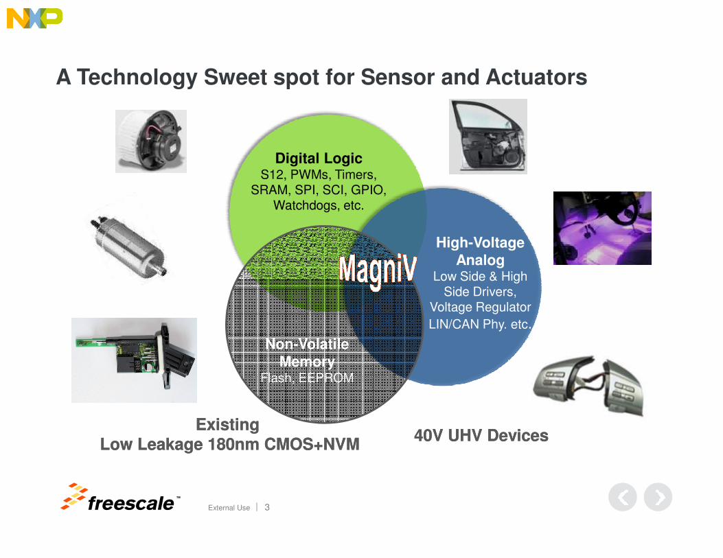
A Technology Sweet spot for Sensor and Actuators
Digital LogicS12, PWMs, Timers,
SRAM, SPI, SCI, GPIO,Watchdogs, etc.
High-Voltage
AnalogLow Side & High
TM
External Use 3
Low Side & HighSide Drivers,
Voltage Regulator
LIN/CAN Phy. etc.
Non-Volatile
MemoryFlash, EEPROM
Existing Existing Low Leakage 180nm CMOS+NVMLow Leakage 180nm CMOS+NVM
40V UHV Devices40V UHV Devices
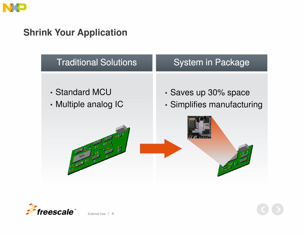
• Standard MCU
• Multiple analog IC
• Saves up 30% space
• Simplifies manufacturing
Traditional SolutionsTraditional Solutions System in PackageSystem in Package
Shrink Your Application
TM
External Use 4
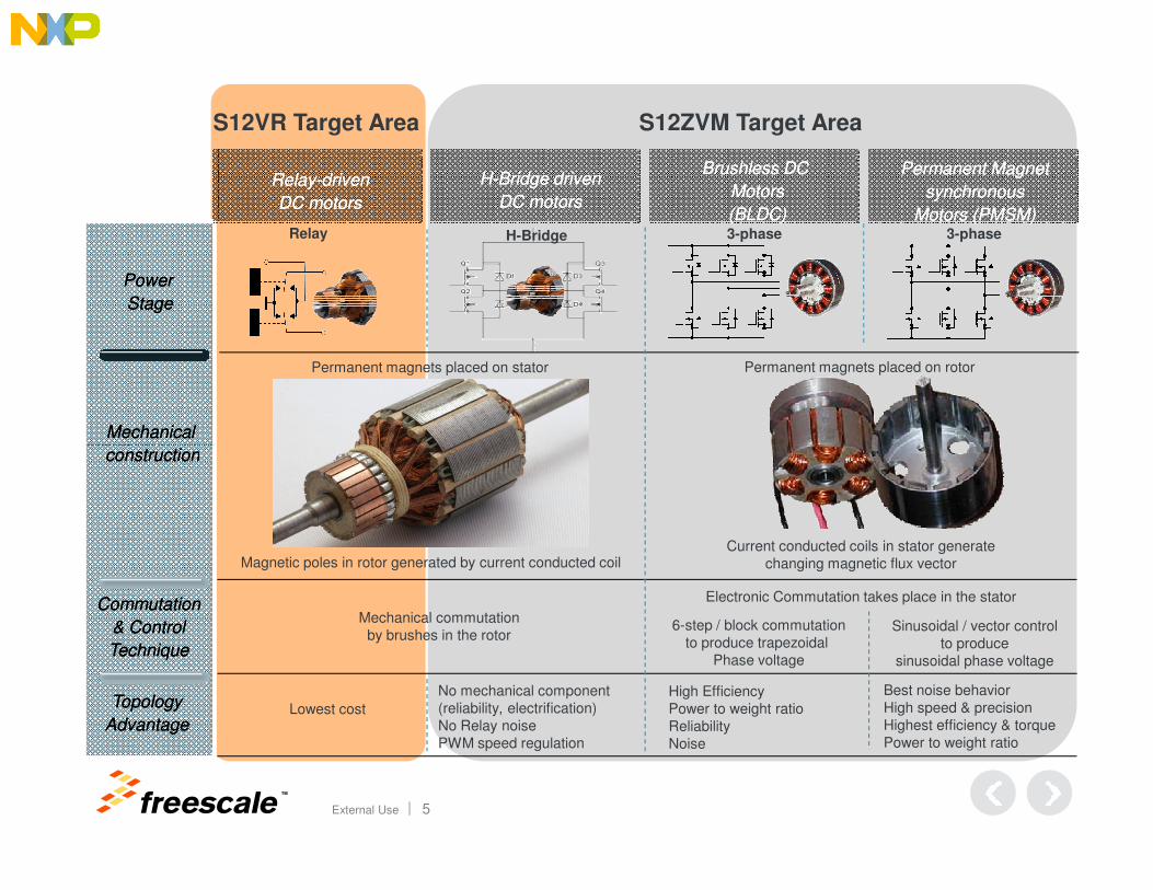
S12VR Target Area S12ZVM Target Area
Relay-driven
DC motors
Relay-driven
DC motors
H-Bridge driven
DC motors
H-Bridge driven
DC motors
Brushless DC
Motors
(BLDC)
Brushless DC
Motors
(BLDC)
Permanent Magnet
synchronous
Motors (PMSM)
Permanent Magnet
synchronous
Motors (PMSM)
Power
Stage
Power
Stage
Mechanical
construction
Mechanical
construction
Relay H-Bridge 3-phase 3-phase
Permanent magnets placed on stator Permanent magnets placed on rotor
TM
External Use 5
constructionconstruction
6-step / block commutationto produce trapezoidal
Phase voltage
Sinusoidal / vector controlto produce
sinusoidal phase voltage
Mechanical commutationby brushes in the rotor
Commutation
& Control
Technique
Commutation
& Control
Technique
Electronic Commutation takes place in the stator
Current conducted coils in stator generate changing magnetic flux vector
Topology
Advantage
Topology
AdvantageLowest cost
No mechanical component(reliability, electrification)No Relay noisePWM speed regulation
High Efficiency Power to weight ratioReliabilityNoise
Best noise behaviorHigh speed & precisionHighest efficiency & torquePower to weight ratio
Magnetic poles in rotor generated by current conducted coil
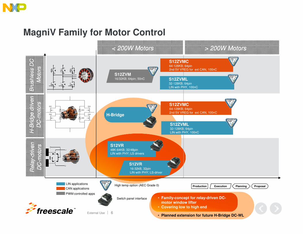
MagniV Family for Motor ControlB
ridge d
riven
moto
rs
Bridge d
riven
moto
rs
Bru
shle
ss D
C
Moto
rs
Bru
shle
ss D
C
Moto
rs
S12ZVML32-128KB; 64pinLIN with PHY, 100nC
S12ZVML32-128KB; 64pinLIN with PHY, 100nC
S12ZVMC64-128KB; 64pin2nd 5V VREG for ext CAN, 100nC
S12ZVMC64-128KB; 64pin2nd 5V VREG for ext CAN, 100nC
S12ZVM16/32KB; 64pin; 50nC
S12ZVMC64-128KB; 64pin2nd 5V VREG for ext CAN, 100nC
S12ZVMC64-128KB; 64pin2nd 5V VREG for ext CAN, 100nC
< 200W Motors< 200W Motors > 200W Motors> 200W Motors
H-Bridge
TM
External Use 6• Planned extension for future H-Bridge DC-WL
• Family-concept for relay-driven DC-
motor window lifter
• Covering low to high end
Production ProposalPlanningExecution
Rela
y-d
riven
DC
-moto
rs
Rela
y-d
riven
DC
-moto
rs
H-B
ridge d
riven
DC
-moto
rs
H-B
ridge d
riven
DC
-moto
rs
S12VR 48K-64KB; 32/48pinLIN with PHY; LS drivers
S12VR 48K-64KB; 32/48pinLIN with PHY; LS drivers
S12ZVML32-128KB; 64pinLIN with PHY, 100nC
S12ZVML32-128KB; 64pinLIN with PHY, 100nC
LIN applications
CAN applications
PWM controlled apps
High temp option (AEC Grade 0)
Switch panel interface
S12VR 16-32kB, 32pinLIN with PHY; LS-driver
S12VR 16-32kB, 32pinLIN with PHY; LS-driver
H-Bridge
TM
External Use 7
S12 CPU with an integrated Voltage regulator, LIN physical layer and HS/LS-drivers for Relay-driven Window Lift motor
4 HV Inputs
1616--64kB 64kB
Flash (ECC)Flash (ECC)
2 kB RAM
128-512BEEPROM
(ECC)
PLLRCosc.
+/-1.3%
PierceOsc.
S12 25MHz Bus2 Low Side
Drivers
2 HS Drivers
TempSense
10-Bit ADC
VsupsenseVreg
70mA
LIN -PHY
SPI
1#EVdd
SCI 1 SCI 0
TIM 16b4ch
G
PIO
Vbatsense
PWM 8ch 8bor 4ch 16b
BDM KWUWin
Wdog
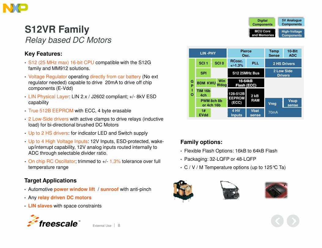
S12VR FamilyRelay based DC Motors
High-VoltageComponents
DigitalComponents
5V AnalogueComponents
MCU Coreand Memories
Key Features:
• S12 (25 MHz max) 16-bit CPU compatible with the S12G family and MM912 solutions.
• Voltage Regulator operating directly from car battery (No ext regulator needed) capable to drive 20mA to drive off chip components (E-Vdd)
• LIN Physical Layer: LIN 2.x / J2602 compliant; +/- 8kV ESD capability
• True 512B EEPROM with ECC, 4 byte erasable
• 2 Low-Side drivers with active clamps to drive relays (inductive load) for bi-directional brushed DC Motors
TM
External Use 8
load) for bi-directional brushed DC Motors
• Up to 2 HS drivers: for indicator LED and Switch supply
• Up to 4 High Voltage Inputs: 12V Inputs, ESD-protected, wake-up/interrupt capability, 12V analog inputs routed internally to ADC through selectable divider ratio.
• On chip RC Oscillator; trimmed to +/- 1,3% tolerance over full temperature range
Family options:
• Flexible Flash Options: 16kB to 64kB Flash
• Packaging: 32-LQFP or 48-LQFP
• C / V / M Temperature options (up to 125°C Ta)
Target Applications
• Automotive power window lift / sunroof with anti-pinch
• Any relay driven DC motors
• LIN slaves with space constraints
PLLRCosc.+/-1.3%
Pierce
Osc.
S12 25MHz Bus2 Low Side
Drivers
2 HS Drivers
Temp
Sense
10-Bit
ADCLIN -PHY
SPI
SCI 1 SCI 0
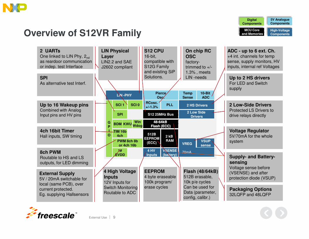
Overview of S12VR Family
Up to 2 HS driversFor LED and Switch supply
2 Low-Side DriversProtected LS Drivers to drive relays directly
High-VoltageComponents
DigitalComponents
5V AnalogueComponents
MCU Coreand Memories
S12 CPU16-bit, compatible with S12G Family and existing SiP Solutions.
ADC - up to 6 ext. Ch.+4 int. channels for tempsense, supply monitors, HV inputs, internal ref Voltages
On chip RC OSCfactory-trimmed to +/-1.3% , meetsLIN -needs
Up to 16 Wakeup pinsCombined with Analog Input pins and HV pins
SPIAs alternative test Interf.
2 UARTsOne linked to LIN Phy, 2nd
as reardoor communicationor indep. test Interface
LIN Physical
LayerLIN2.2 and SAE J2602 compliant
TM
External Use 9
4 HV Inputs
4848--64kB 64kB Flash (ECC)Flash (ECC)
2 kB RAM
512BEEPROM
(ECC) VSUPsenseVREG
70mA1#EVDD
TIM 16b4ch
GPIO
VSENSE(battery)
PWM 8ch 8bor 4ch 16b
BDM KWUWin
Wdog
Supply- and Battery-sensingVoltage sense before(VSENSE) and after protection diode (VSUP)
EEPROM4 byte eraseable100k program/ erase cycles
Packaging Options32LQFP and 48LQFP
Flash (48/64kB)512B erasable, 10k p/e cyclesCan be used forData (parameter, config, calibr.)
4ch 16bit TimerHall inputs, SW timing
8ch PWMRoutable to HS and LS outputs, for LED dimming
4 High Voltage Inputs12V Inputs for Switch MonitoringRoutable to ADC
External Supply5V / 20mA switchable forlocal (same PCB), overcurrent protected. Eg. supplying Hallsensors
Voltage Regulator5V/70mA for the wholesystem
PLLRCosc.+/-1.3%
Pierce
Osc.
S12 25MHz Bus 2 LS Drivers2 LS Drivers
2 HS Drivers2 HS Drivers
Temp
Sense
10-Bit
ADCLIN LIN --PHYPHY
SPI
SCI 1 SCI 0
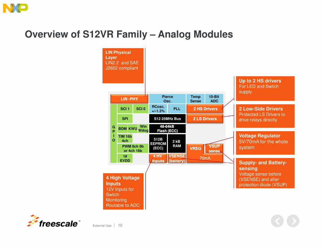
Overview of S12VR Family – Analog Modules
Up to 2 HS driversFor LED and Switch supply
2 Low-Side DriversProtected LS Drivers to drive relays directly
LIN Physical Layer
LIN2.2 and SAE J2602 compliant
TM
External Use 10
4 HV 4 HV
InputsInputs
4848--64kB 64kB Flash (ECC)Flash (ECC)
2 kB RAM
512BEEPROM
(ECC)VSUPVSUP
sensesense
1#EVDD
TIM 16b4ch
GPIO
VSENSEVSENSE
(battery)(battery)
PWM 8ch 8bor 4ch 16b
BDM KWUWin
Wdog
Supply- and Battery-sensingVoltage sense before (VSENSE) and after protection diode (VSUP)
4 High Voltage Inputs12V Inputs for Switch MonitoringRoutable to ADC
Voltage Regulator5V/70mA for the whole systemVREGVREG
70mA70mA
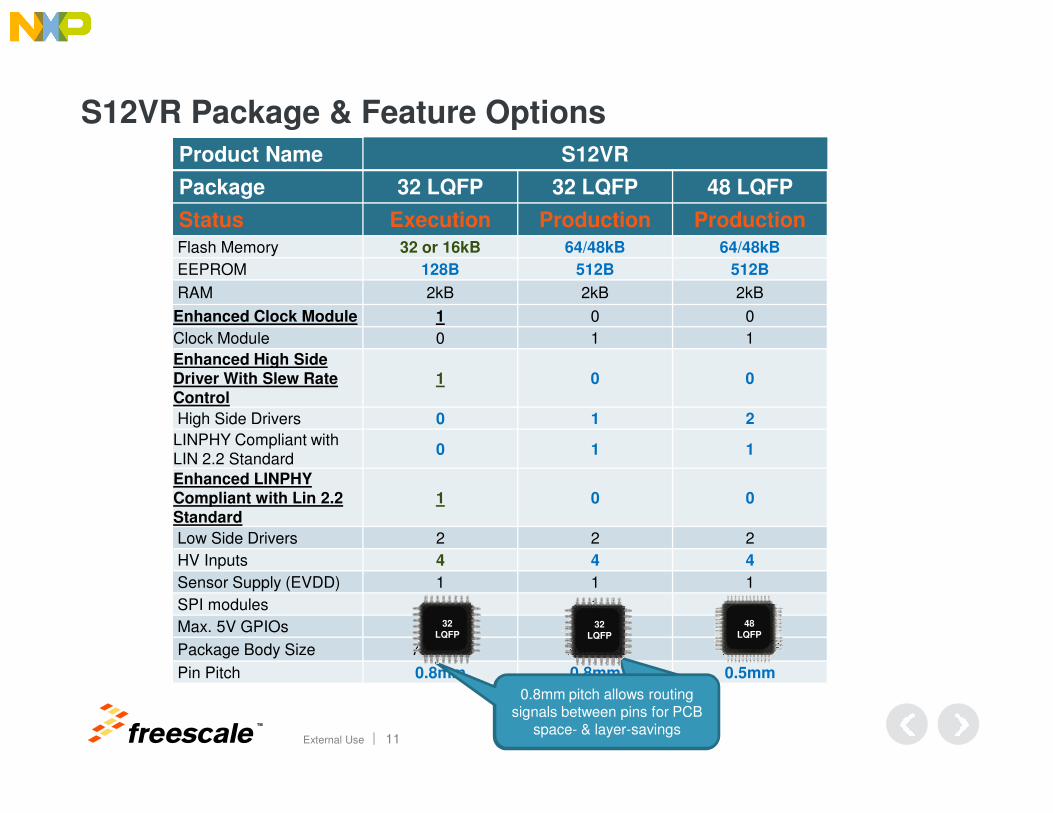
S12VR Package & Feature Options
Product Name S12VR
Package 32 LQFP 32 LQFP 48 LQFP
Status Execution Production Production
Flash Memory 32 or 16kB 64/48kB 64/48kB
EEPROM 128B 512B 512B
RAM 2kB 2kB 2kB
Enhanced Clock Module 1 0 0
Clock Module 0 1 1
Enhanced High Side Driver With Slew Rate Control
1 0 0
TM
External Use 11
High Side Drivers 0 1 2
LINPHY Compliant with LIN 2.2 Standard
0 1 1
Enhanced LINPHY
Compliant with Lin 2.2 Standard
1 0 0
Low Side Drivers 2 2 2
HV Inputs 4 4 4
Sensor Supply (EVDD) 1 1 1
SPI modules - 1 1
Max. 5V GPIOs 16 16 28
Package Body Size 7x7mm2 7x7mm2 7x7mm2
Pin Pitch 0.8mm 0.8mm 0.5mm
0.8mm pitch allows routing signals between pins for PCB
space- & layer-savings
0.8mm pitch allows routing signals between pins for PCB
space- & layer-savings
32
LQFP32
LQFP
48
LQFP
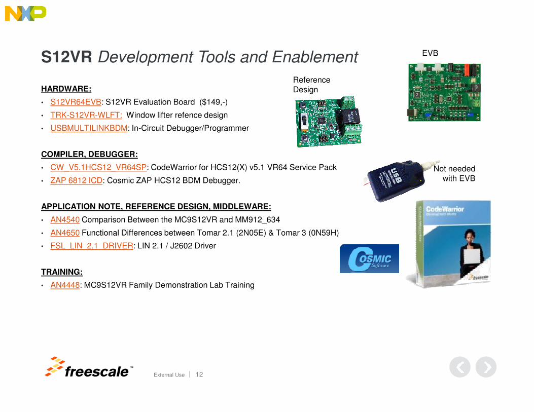
S12VR Development Tools and Enablement
HARDWARE:
• S12VR64EVB: S12VR Evaluation Board ($149,-)
• TRK-S12VR-WLFT: Window lifter refence design
• USBMULTILINKBDM: In-Circuit Debugger/Programmer
COMPILER, DEBUGGER:
• CW_V5.1HCS12_VR64SP: CodeWarrior for HCS12(X) v5.1 VR64 Service Pack
• ZAP 6812 ICD: Cosmic ZAP HCS12 BDM Debugger.
APPLICATION NOTE, REFERENCE DESIGN, MIDDLEWARE:
Not neededwith EVB
EVB
Reference Design
TM
External Use 12
APPLICATION NOTE, REFERENCE DESIGN, MIDDLEWARE:
• AN4540 Comparison Between the MC9S12VR and MM912_634
• AN4650 Functional Differences between Tomar 2.1 (2N05E) & Tomar 3 (0N59H)
• FSL_LIN_2.1_DRIVER: LIN 2.1 / J2602 Driver
TRAINING:
• AN4448: MC9S12VR Family Demonstration Lab Training
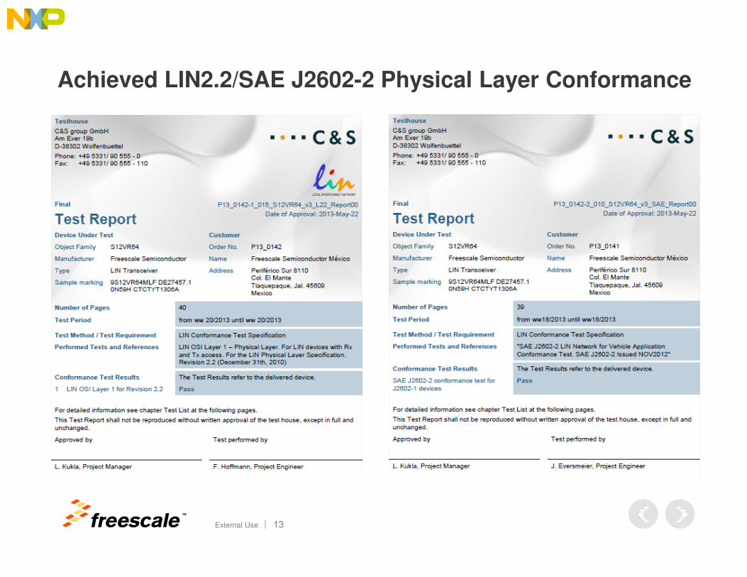
Achieved LIN2.2/SAE J2602-2 Physical Layer Conformance
TM
External Use 13
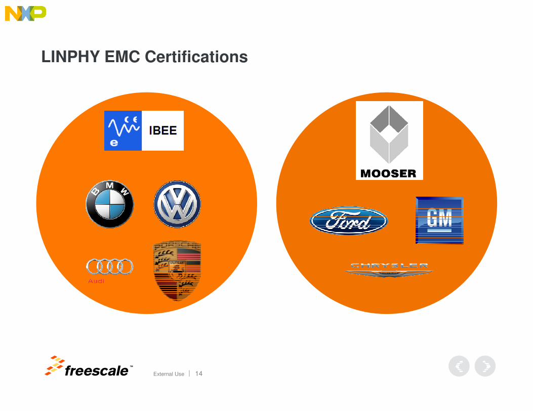
LINPHY EMC Certifications
TM
External Use 14
TM
External Use 15
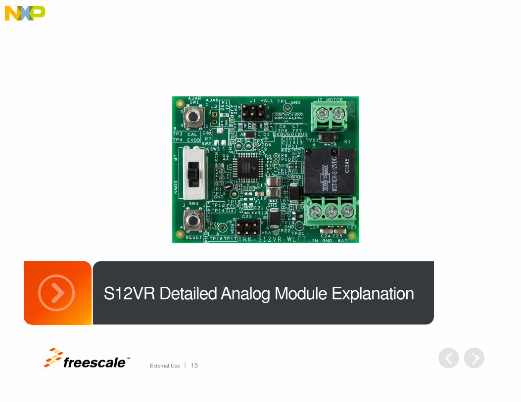
S12VR Detailed Analog Module Explanation
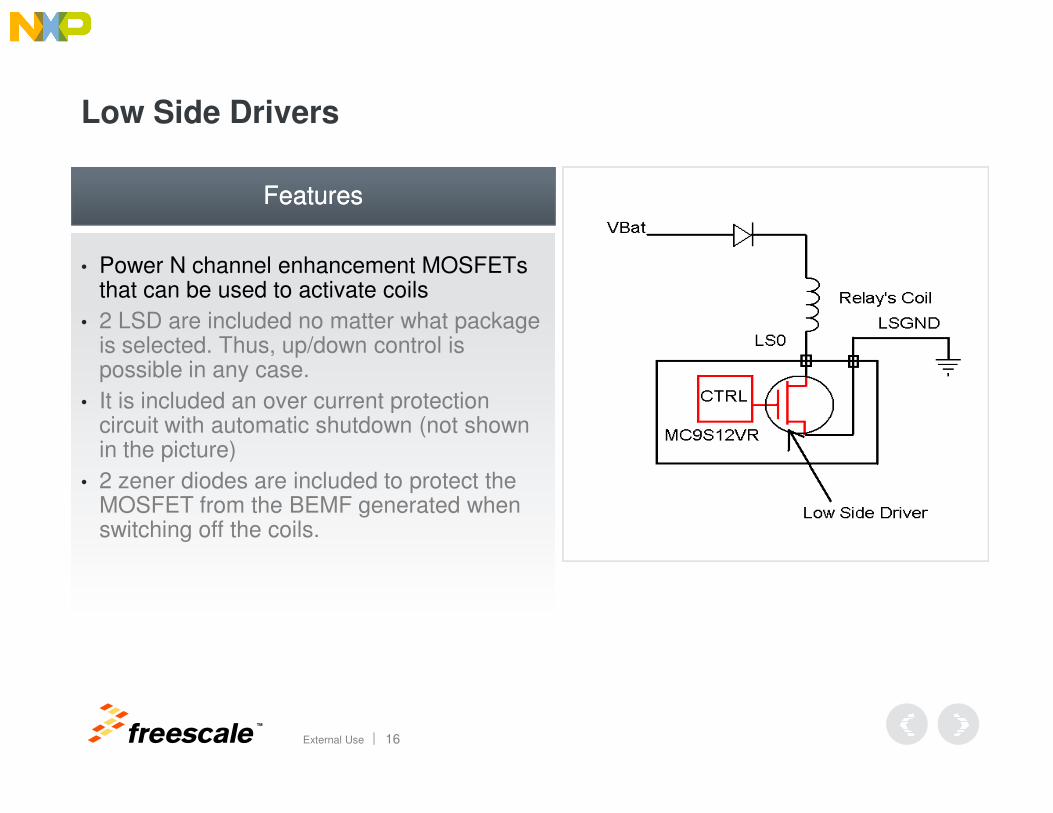
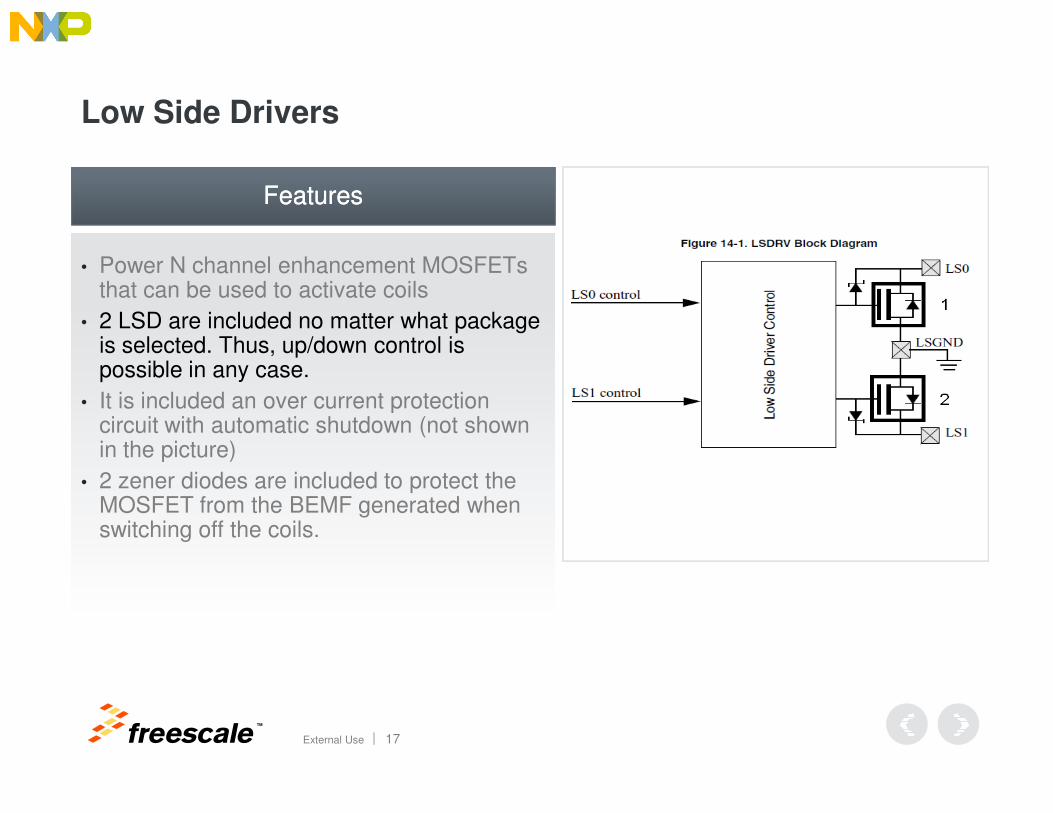
Low Side Drivers
• Power N channel enhancement MOSFETs that can be used to activate coils
• 2 LSD are included no matter what package is selected. Thus, up/down control is possible in any case.
• It is included an over current protection
FeaturesFeatures
TM
External Use 16
• It is included an over current protection circuit with automatic shutdown (not shown in the picture)
• 2 zener diodes are included to protect the MOSFET from the BEMF generated when switching off the coils.
Low Side Drivers
• Power N channel enhancement MOSFETs that can be used to activate coils
• 2 LSD are included no matter what package is selected. Thus, up/down control is possible in any case.
• It is included an over current protection
FeaturesFeatures
TM
External Use 17
• It is included an over current protection circuit with automatic shutdown (not shown in the picture)
• 2 zener diodes are included to protect the MOSFET from the BEMF generated when switching off the coils.
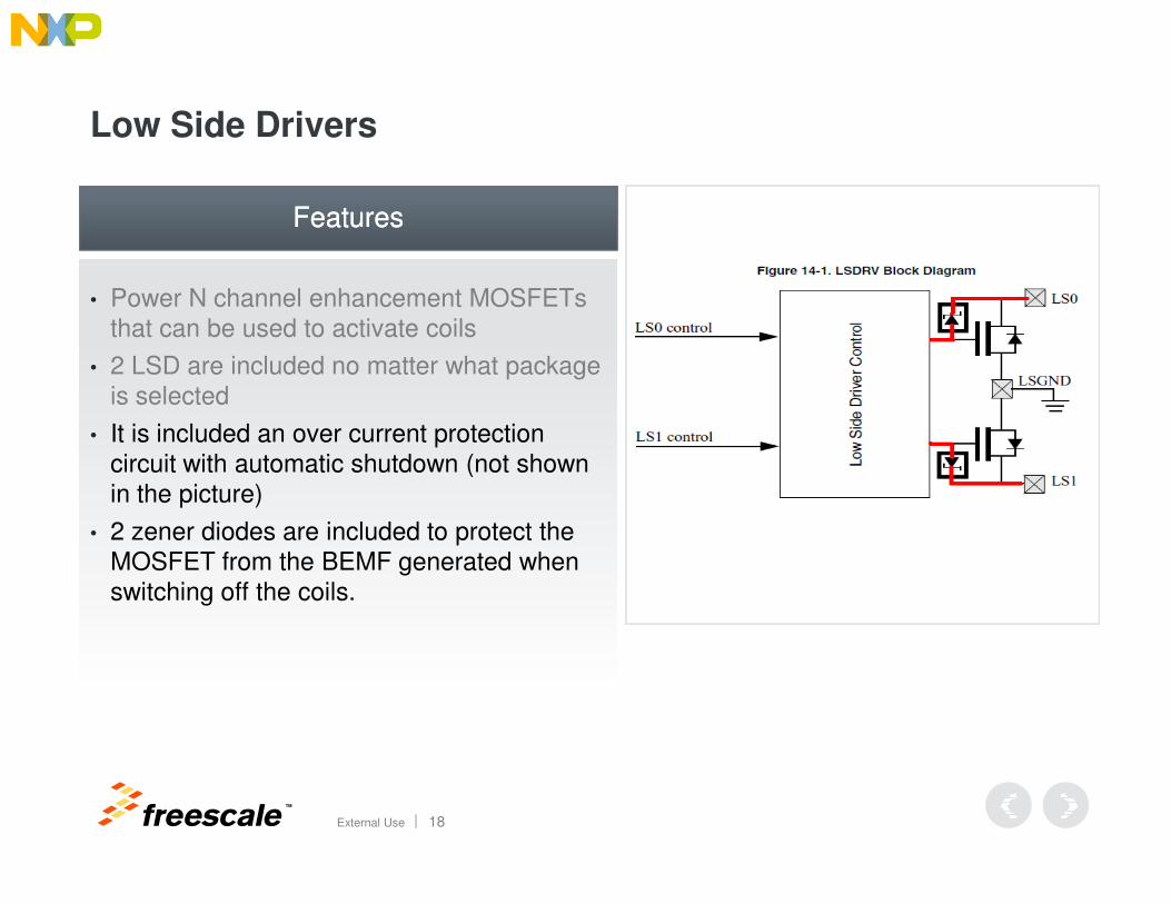
Low Side Drivers
• Power N channel enhancement MOSFETs that can be used to activate coils
• 2 LSD are included no matter what package is selected
• It is included an over current protection circuit with automatic shutdown (not shown
FeaturesFeatures
TM
External Use 18
circuit with automatic shutdown (not shown in the picture)
• 2 zener diodes are included to protect the MOSFET from the BEMF generated when switching off the coils.
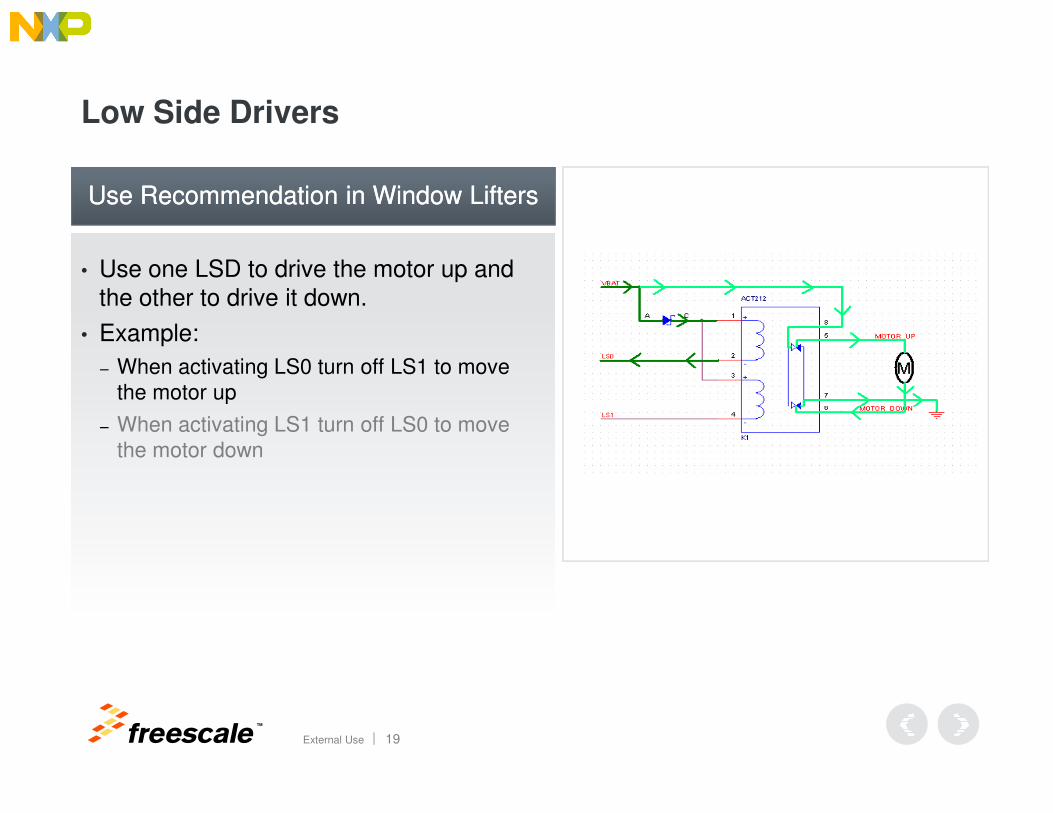
Low Side Drivers
• Use one LSD to drive the motor up and the other to drive it down.
• Example:
− When activating LS0 turn off LS1 to move the motor up
Use Recommendation in Window LiftersUse Recommendation in Window Lifters
TM
External Use 19
− When activating LS1 turn off LS0 to move the motor down
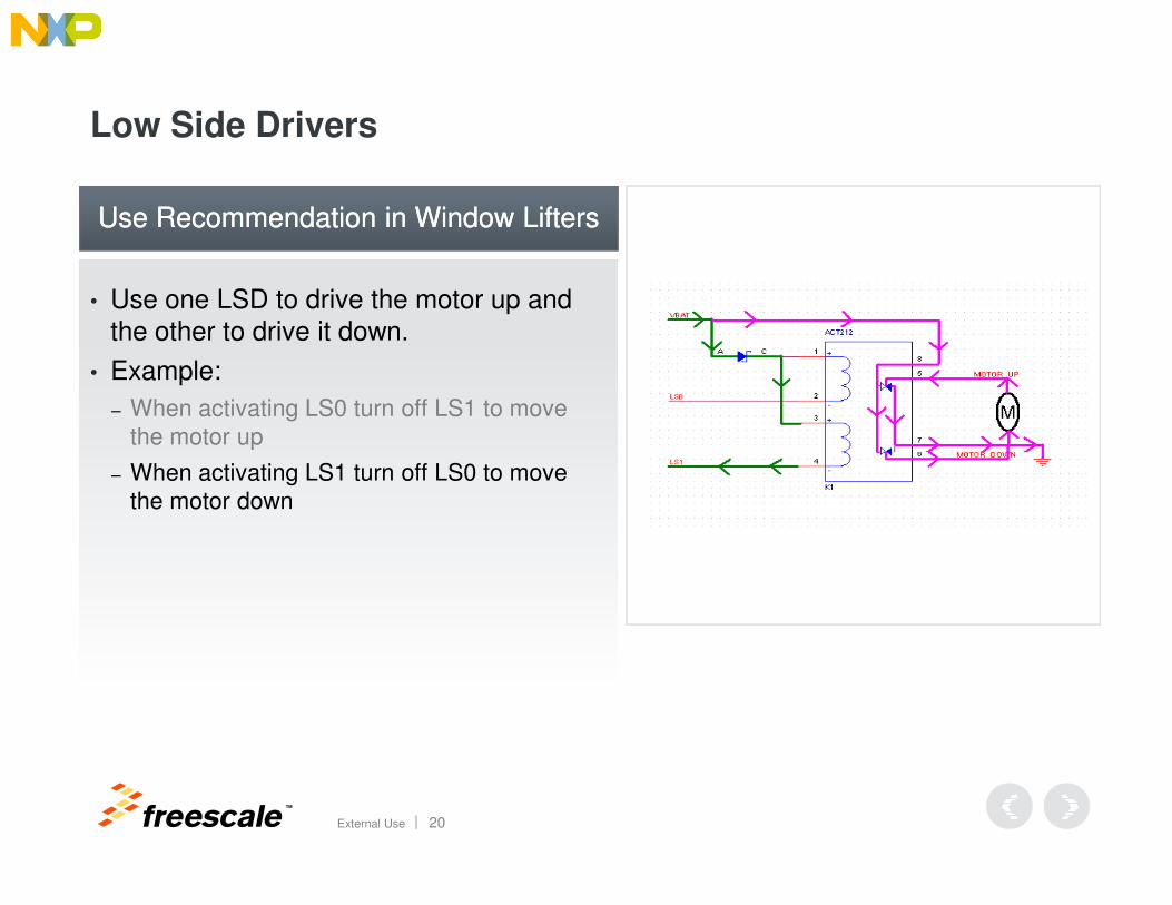
Low Side Drivers
• Use one LSD to drive the motor up and the other to drive it down.
• Example:
− When activating LS0 turn off LS1 to move the motor up
Use Recommendation in Window LiftersUse Recommendation in Window Lifters
TM
External Use 20
− When activating LS1 turn off LS0 to move the motor down
High Voltage Input
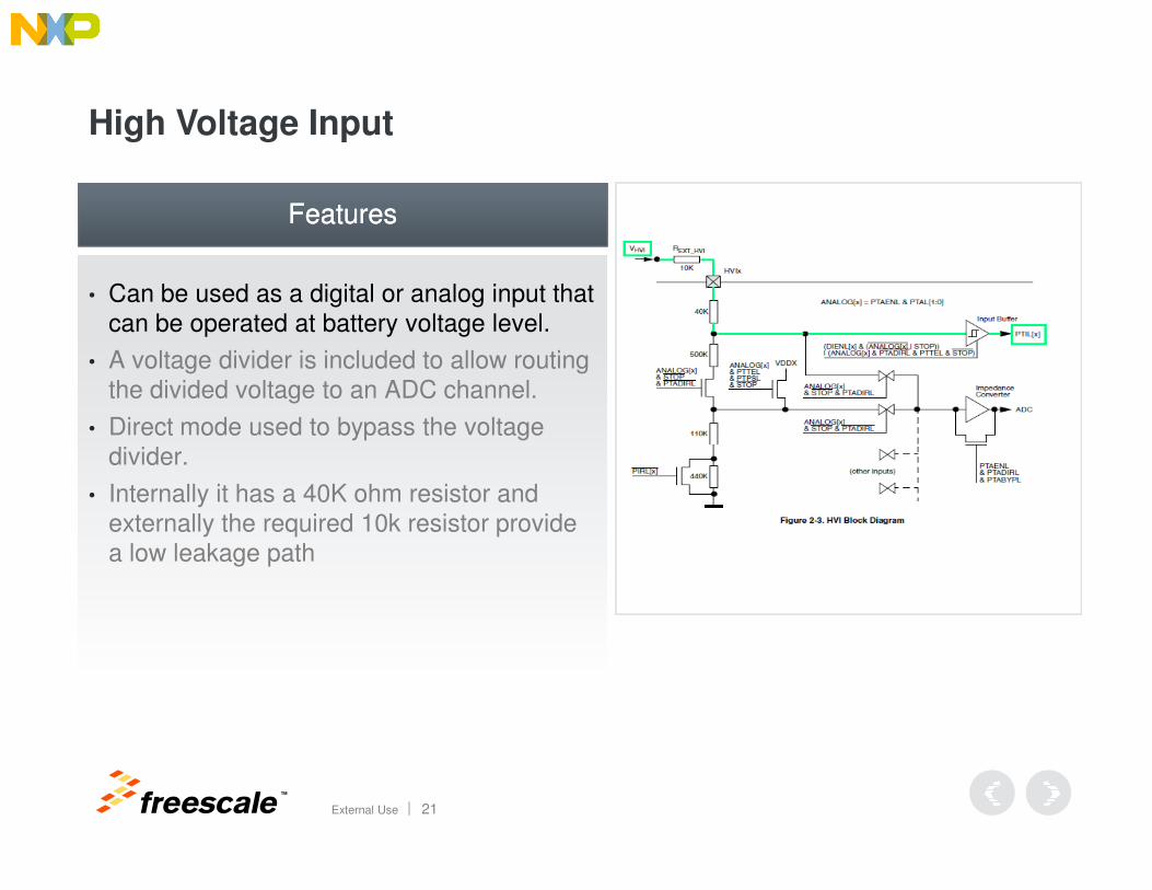
• Can be used as a digital or analog input that can be operated at battery voltage level.
• A voltage divider is included to allow routing the divided voltage to an ADC channel.
• Direct mode used to bypass the voltage divider.
FeaturesFeatures
TM
External Use 21
divider.
• Internally it has a 40K ohm resistor and externally the required 10k resistor provide a low leakage path

High Voltage Input
• Can be used as a digital or analog input that can be operated at battery voltage level.
• A voltage divider is included to allow routing the divided voltage to an ADC channel.
• Direct mode used to bypass the voltage divider.
FeaturesFeatures
TM
External Use 22
divider.
• Internally it has a 40K ohm resistor and externally the required 10k resistor provide a low leakage path
High Voltage Input
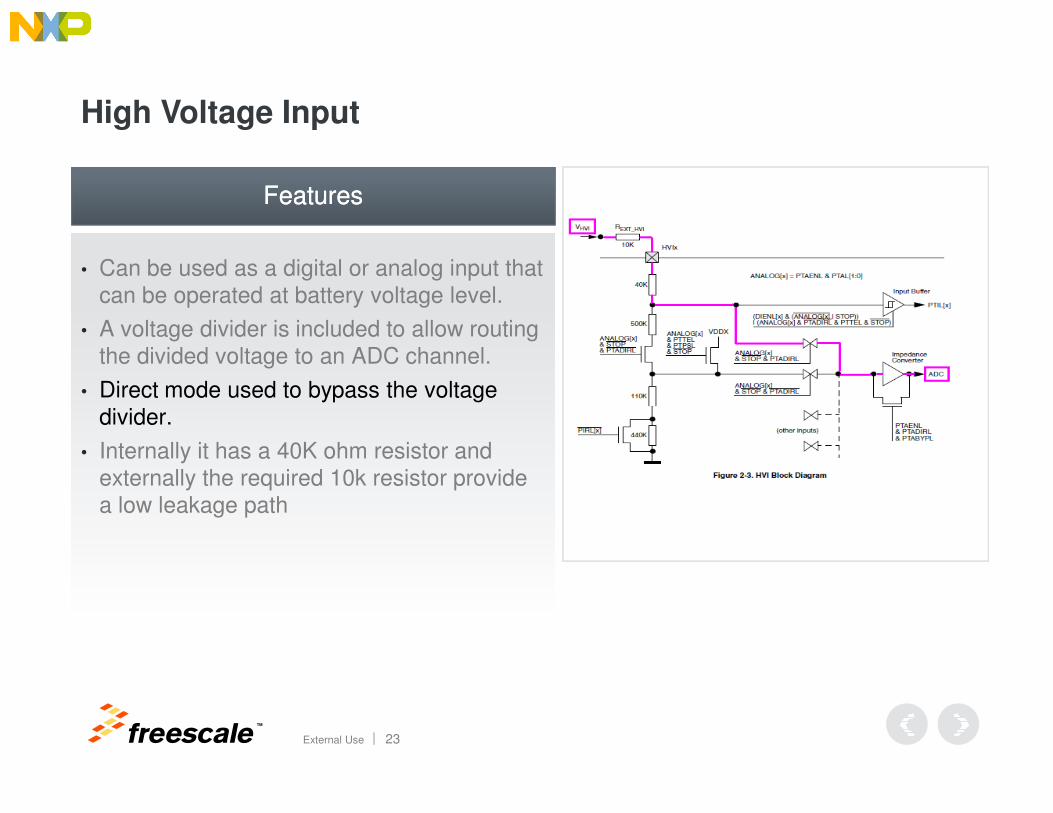
• Can be used as a digital or analog input that can be operated at battery voltage level.
• A voltage divider is included to allow routing the divided voltage to an ADC channel.
• Direct mode used to bypass the voltage divider.
FeaturesFeatures
TM
External Use 23
divider.
• Internally it has a 40K ohm resistor and externally the required 10k resistor provide a low leakage path
High Voltage Input
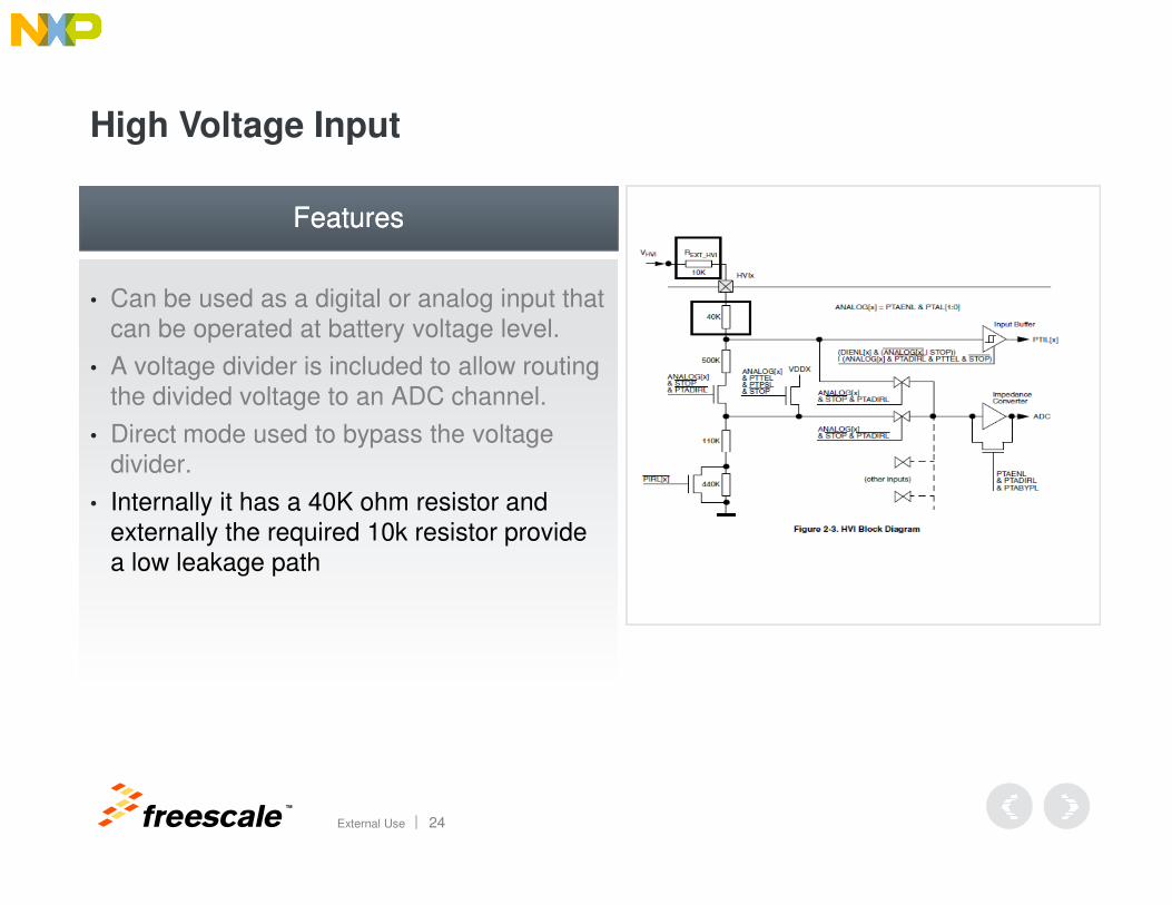
• Can be used as a digital or analog input that can be operated at battery voltage level.
• A voltage divider is included to allow routing the divided voltage to an ADC channel.
• Direct mode used to bypass the voltage divider.
FeaturesFeatures
TM
External Use 24
divider.
• Internally it has a 40K ohm resistor and externally the required 10k resistor provide a low leakage path
High Voltage Input
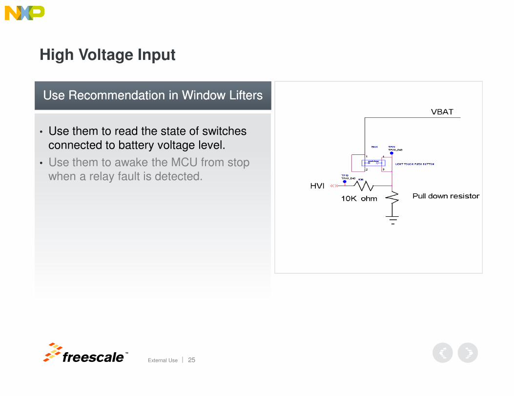
• Use them to read the state of switches connected to battery voltage level.
• Use them to awake the MCU from stop when a relay fault is detected.
Use Recommendation in Window LiftersUse Recommendation in Window Lifters
TM
External Use 25
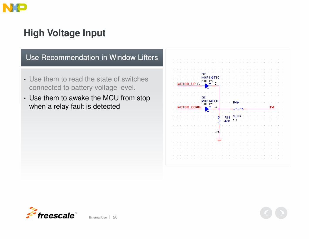
High Voltage Input
• Use them to read the state of switches connected to battery voltage level.
• Use them to awake the MCU from stop when a relay fault is detected
Use Recommendation in Window LiftersUse Recommendation in Window Lifters
TM
External Use 26
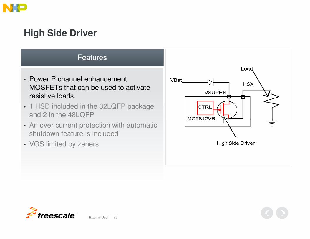
High Side Driver
• Power P channel enhancement MOSFETs that can be used to activate resistive loads.
• 1 HSD included in the 32LQFP package and 2 in the 48LQFP
FeaturesFeatures
TM
External Use 27
• An over current protection with automatic shutdown feature is included
• VGS limited by zeners
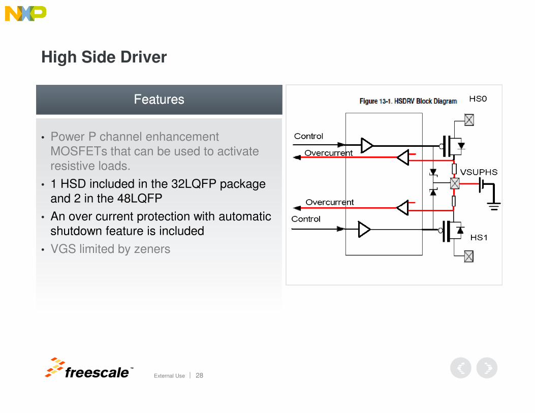
High Side Driver
• Power P channel enhancement MOSFETs that can be used to activate resistive loads.
• 1 HSD included in the 32LQFP package and 2 in the 48LQFP
FeaturesFeatures
TM
External Use 28
• An over current protection with automatic shutdown feature is included
• VGS limited by zeners
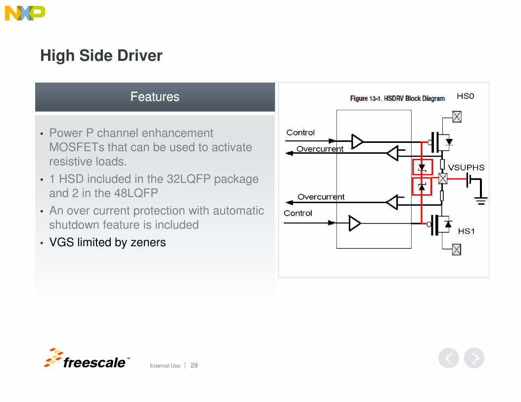
High Side Driver
• Power P channel enhancement MOSFETs that can be used to activate resistive loads.
• 1 HSD included in the 32LQFP package and 2 in the 48LQFP
FeaturesFeatures
TM
External Use 29
• An over current protection with automatic shutdown feature is included
• VGS limited by zeners
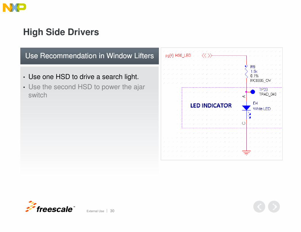
High Side Drivers
• Use one HSD to drive a search light.
• Use the second HSD to power the ajar switch
Use Recommendation in Window LiftersUse Recommendation in Window Lifters
TM
External Use 30
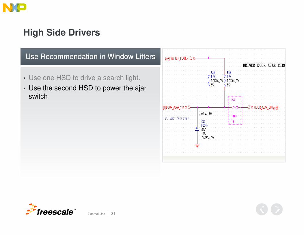
High Side Drivers
• Use one HSD to drive a search light.
• Use the second HSD to power the ajar switch
Use Recommendation in Window LiftersUse Recommendation in Window Lifters
TM
External Use 31
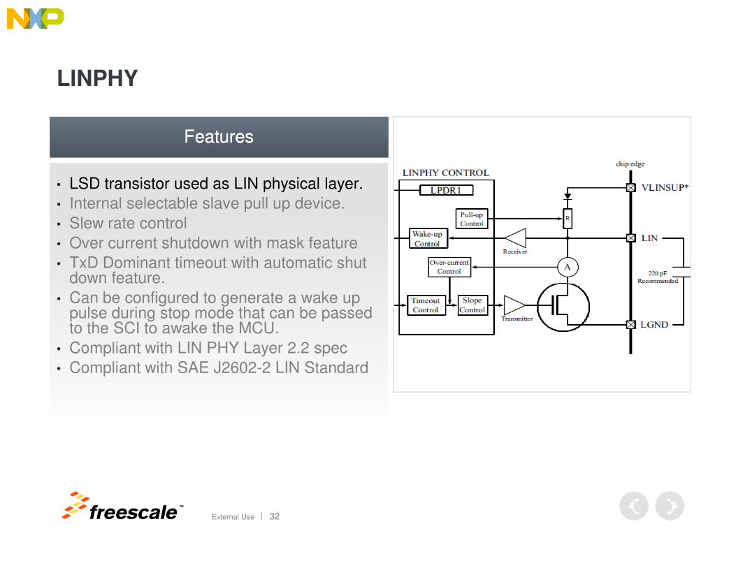
LINPHY
• LSD transistor used as LIN physical layer.
• Internal selectable slave pull up device.
• Slew rate control
• Over current shutdown with mask feature
• TxD Dominant timeout with automatic shut down feature.
FeaturesFeatures
TM
External Use 32
down feature.
• Can be configured to generate a wake up pulse during stop mode that can be passed to the SCI to awake the MCU.
• Compliant with LIN PHY Layer 2.2 spec
• Compliant with SAE J2602-2 LIN Standard
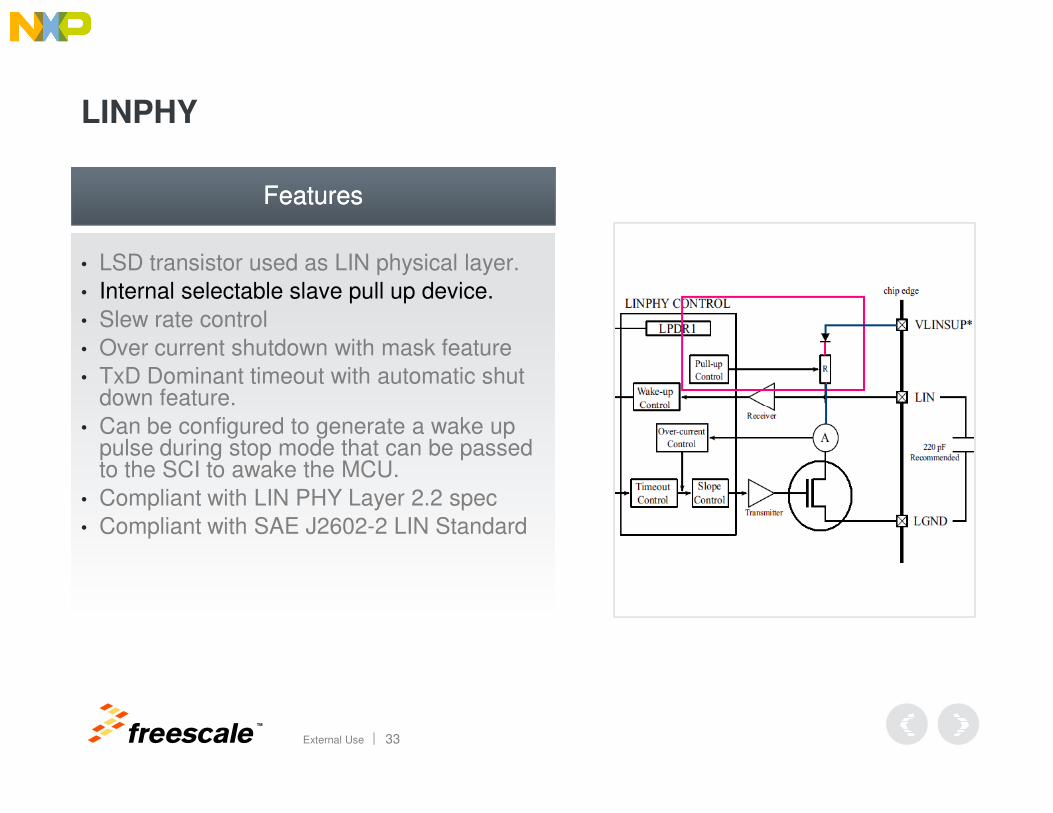
LINPHY
• LSD transistor used as LIN physical layer.
• Internal selectable slave pull up device.
• Slew rate control
• Over current shutdown with mask feature
• TxD Dominant timeout with automatic shut down feature.
FeaturesFeatures
TM
External Use 33
down feature.
• Can be configured to generate a wake up pulse during stop mode that can be passed to the SCI to awake the MCU.
• Compliant with LIN PHY Layer 2.2 spec
• Compliant with SAE J2602-2 LIN Standard
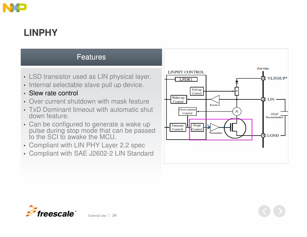
LINPHY
• LSD transistor used as LIN physical layer.
• Internal selectable slave pull up device.
• Slew rate control
• Over current shutdown with mask feature
• TxD Dominant timeout with automatic shut down feature.
FeaturesFeatures
TM
External Use 34
down feature.
• Can be configured to generate a wake up pulse during stop mode that can be passed to the SCI to awake the MCU.
• Compliant with LIN PHY Layer 2.2 spec
• Compliant with SAE J2602-2 LIN Standard

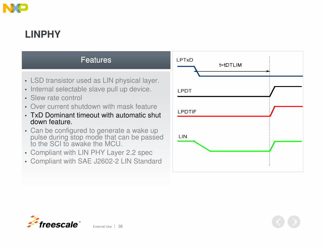
LINPHY
• LSD transistor used as LIN physical layer.
• Internal selectable slave pull up device.
• Slew rate control
• Over current shutdown with mask feature
• TxD Dominant timeout with automatic shut down feature.
FeaturesFeatures
TM
External Use 35
down feature.
• Can be configured to generate a wake up pulse during stop mode that can be passed to the SCI to awake the MCU.
• Compliant with LIN PHY Layer 2.2 spec
• Compliant with SAE J2602-2 LIN Standard
LINPHY
• LSD transistor used as LIN physical layer.
• Internal selectable slave pull up device.
• Slew rate control
• Over current shutdown with mask feature
• TxD Dominant timeout with automatic shut down feature.
FeaturesFeatures
TM
External Use 36
down feature.
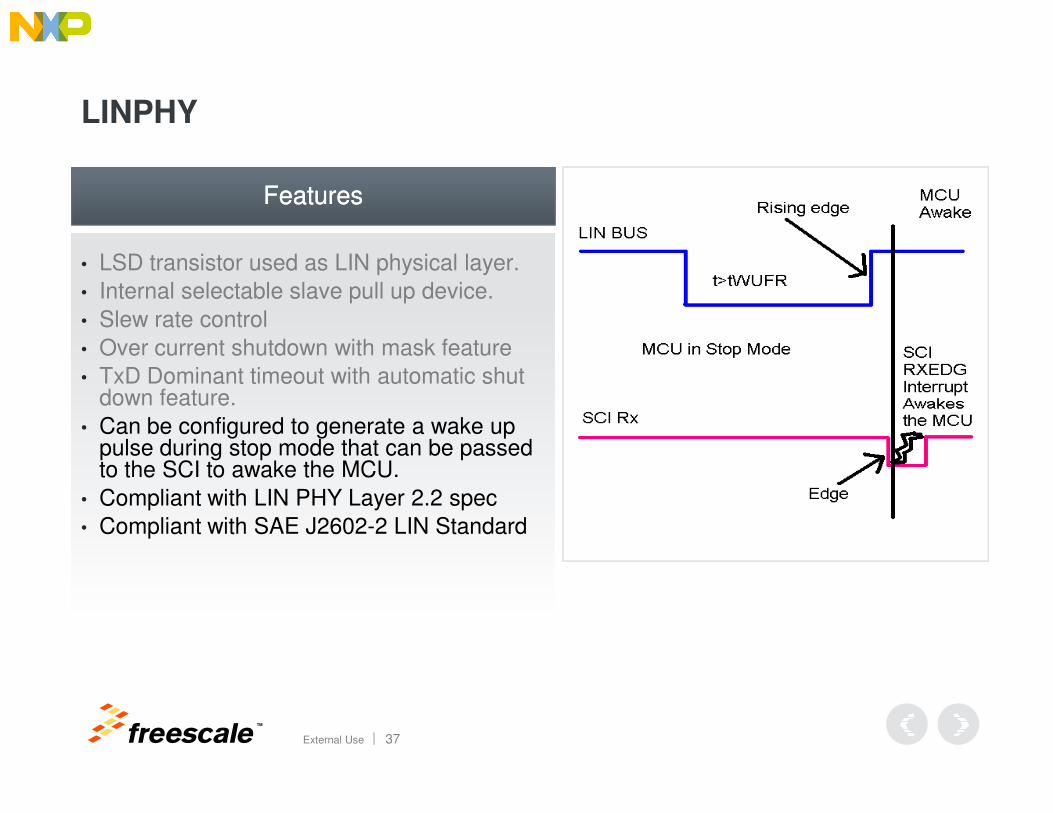
• Can be configured to generate a wake up pulse during stop mode that can be passed to the SCI to awake the MCU.
• Compliant with LIN PHY Layer 2.2 spec
• Compliant with SAE J2602-2 LIN Standard
LINPHY
• LSD transistor used as LIN physical layer.
• Internal selectable slave pull up device.
• Slew rate control
• Over current shutdown with mask feature
• TxD Dominant timeout with automatic shut down feature.
FeaturesFeatures
TM
External Use 37
down feature.
• Can be configured to generate a wake up pulse during stop mode that can be passed to the SCI to awake the MCU.
• Compliant with LIN PHY Layer 2.2 spec
• Compliant with SAE J2602-2 LIN Standard
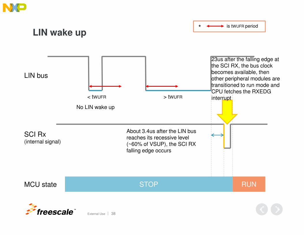
LIN wake up
LIN bus
< tWUFR > tWUFR
No LIN wake up
* is tWUFR period
23us after the falling edge at the SCI RX, the bus clock becomes available, then other peripheral modules are transitioned to run mode and CPU fetches the RXEDG interrupt
TM
External Use 38
SCI Rx(internal signal)
MCU state STOP RUN
About 3.4us after the LIN bus reaches its recessive level (~60% of VSUP), the SCI RX falling edge occurs
TM
External Use 39
FMVSS Powered Window Lift Required Safety Measures
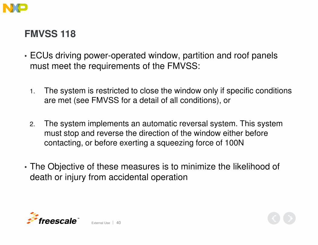
FMVSS 118
• ECUs driving power-operated window, partition and roof panels must meet the requirements of the FMVSS:
1. The system is restricted to close the window only if specific conditions are met (see FMVSS for a detail of all conditions), or
2. The system implements an automatic reversal system. This system
TM
External Use 40
2. The system implements an automatic reversal system. This system must stop and reverse the direction of the window either before contacting, or before exerting a squeezing force of 100N
• The Objective of these measures is to minimize the likelihood of death or injury from accidental operation
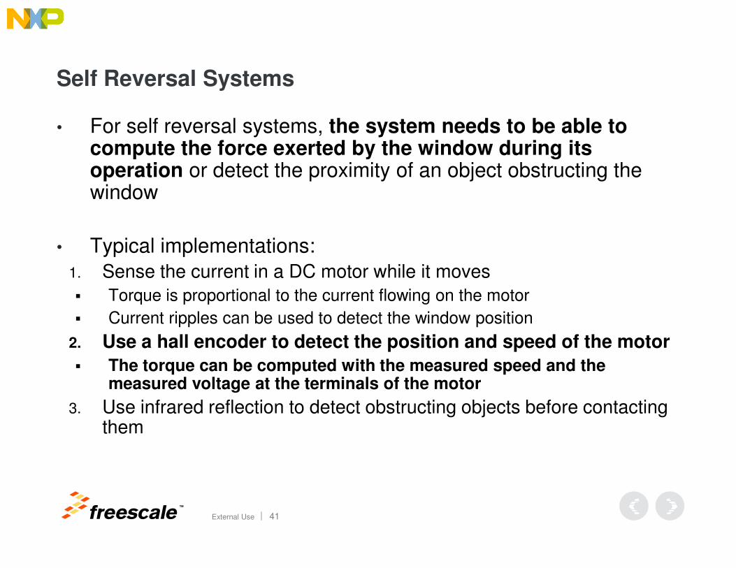
Self Reversal Systems
• For self reversal systems, the system needs to be able to compute the force exerted by the window during its operation or detect the proximity of an object obstructing the window
• Typical implementations:1. Sense the current in a DC motor while it moves
TM
External Use 41
� Torque is proportional to the current flowing on the motor
� Current ripples can be used to detect the window position
2. Use a hall encoder to detect the position and speed of the motor
� The torque can be computed with the measured speed and the measured voltage at the terminals of the motor
3. Use infrared reflection to detect obstructing objects before contacting them

TM
External Use 42
Considerations when Designing Powered Window Lifts
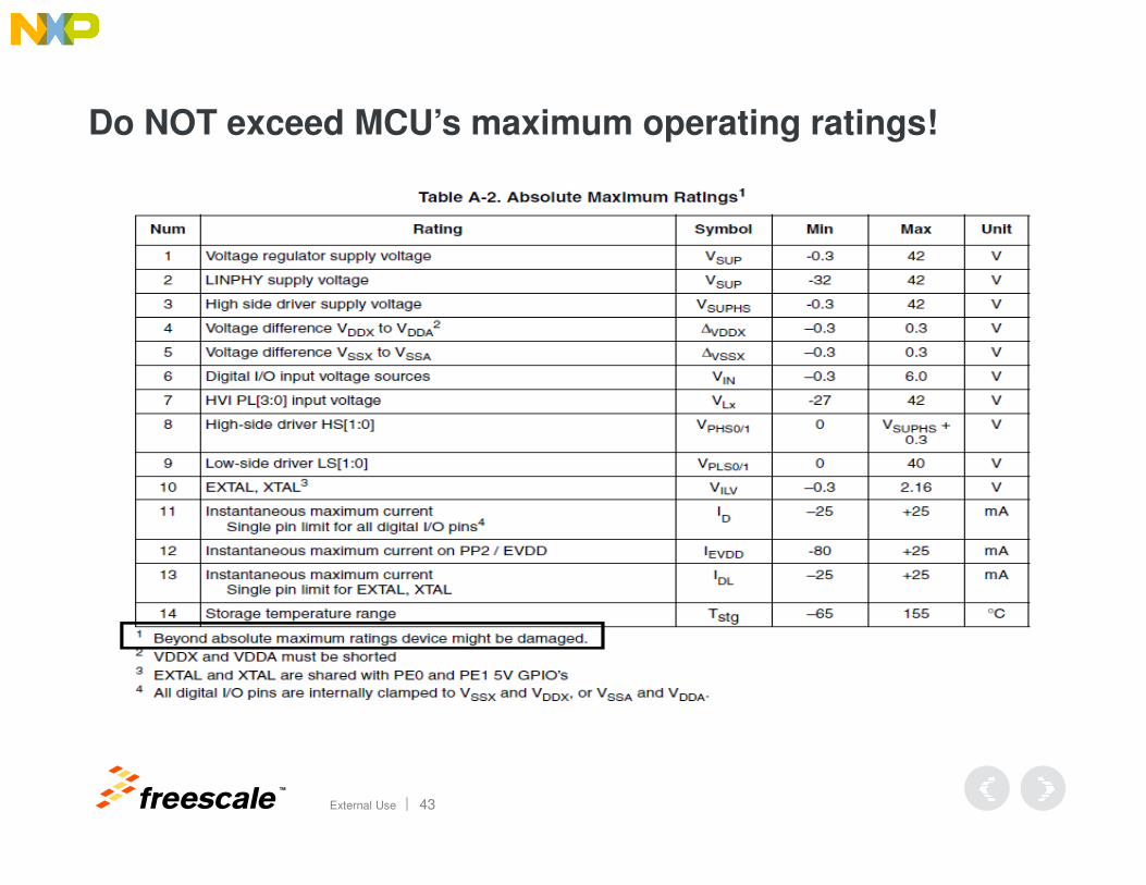
Do NOT exceed MCU’s maximum operating ratings!
TM
External Use 43
Load Dump and Fast Transients
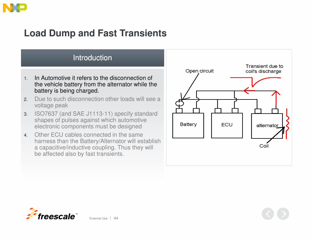
1. In Automotive it refers to the disconnection of the vehicle battery from the alternator while the battery is being charged.
2. Due to such disconnection other loads will see a voltage peak
3. ISO7637 (and SAE J1113-11) specify standard shapes of pulses against which automotive
IntroductionIntroduction
TM
External Use 44
shapes of pulses against which automotive electronic components must be designed
4. Other ECU cables connected in the same harness than the Battery/Alternator will establish a capacitive/inductive coupling. Thus they will be affected also by fast transients.
Load Dump and Fast Transients
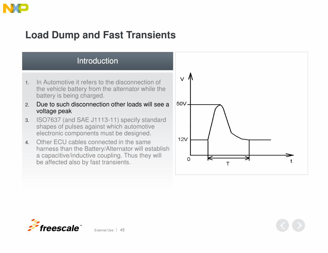
1. In Automotive it refers to the disconnection of the vehicle battery from the alternator while the battery is being charged.
2. Due to such disconnection other loads will see a voltage peak
3. ISO7637 (and SAE J1113-11) specify standard shapes of pulses against which automotive
IntroductionIntroduction
TM
External Use 45
shapes of pulses against which automotive electronic components must be designed.
4. Other ECU cables connected in the same harness than the Battery/Alternator will establish a capacitive/inductive coupling. Thus they will be affected also by fast transients.
Load Dump and Fast Transients
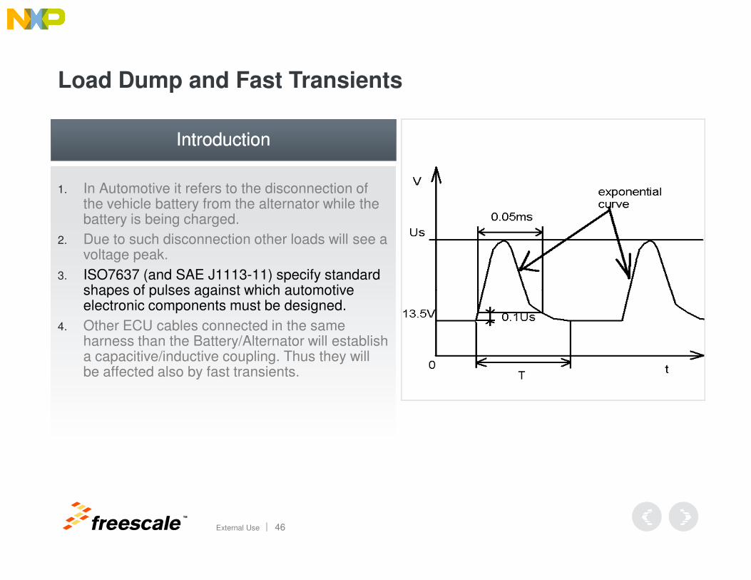
1. In Automotive it refers to the disconnection of the vehicle battery from the alternator while the battery is being charged.
2. Due to such disconnection other loads will see a voltage peak.
3. ISO7637 (and SAE J1113-11) specify standard shapes of pulses against which automotive
IntroductionIntroduction
TM
External Use 46
shapes of pulses against which automotive electronic components must be designed.
4. Other ECU cables connected in the same harness than the Battery/Alternator will establish a capacitive/inductive coupling. Thus they will be affected also by fast transients.
Load Dump and Fast Transients
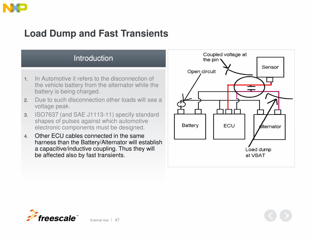
1. In Automotive it refers to the disconnection of the vehicle battery from the alternator while the battery is being charged.
2. Due to such disconnection other loads will see a voltage peak.
3. ISO7637 (and SAE J1113-11) specify standard shapes of pulses against which automotive
IntroductionIntroduction
TM
External Use 47
shapes of pulses against which automotive electronic components must be designed.
4. Other ECU cables connected in the same harness than the Battery/Alternator will establish a capacitive/inductive coupling. Thus they will be affected also by fast transients.
Load Dump and Fast Transients
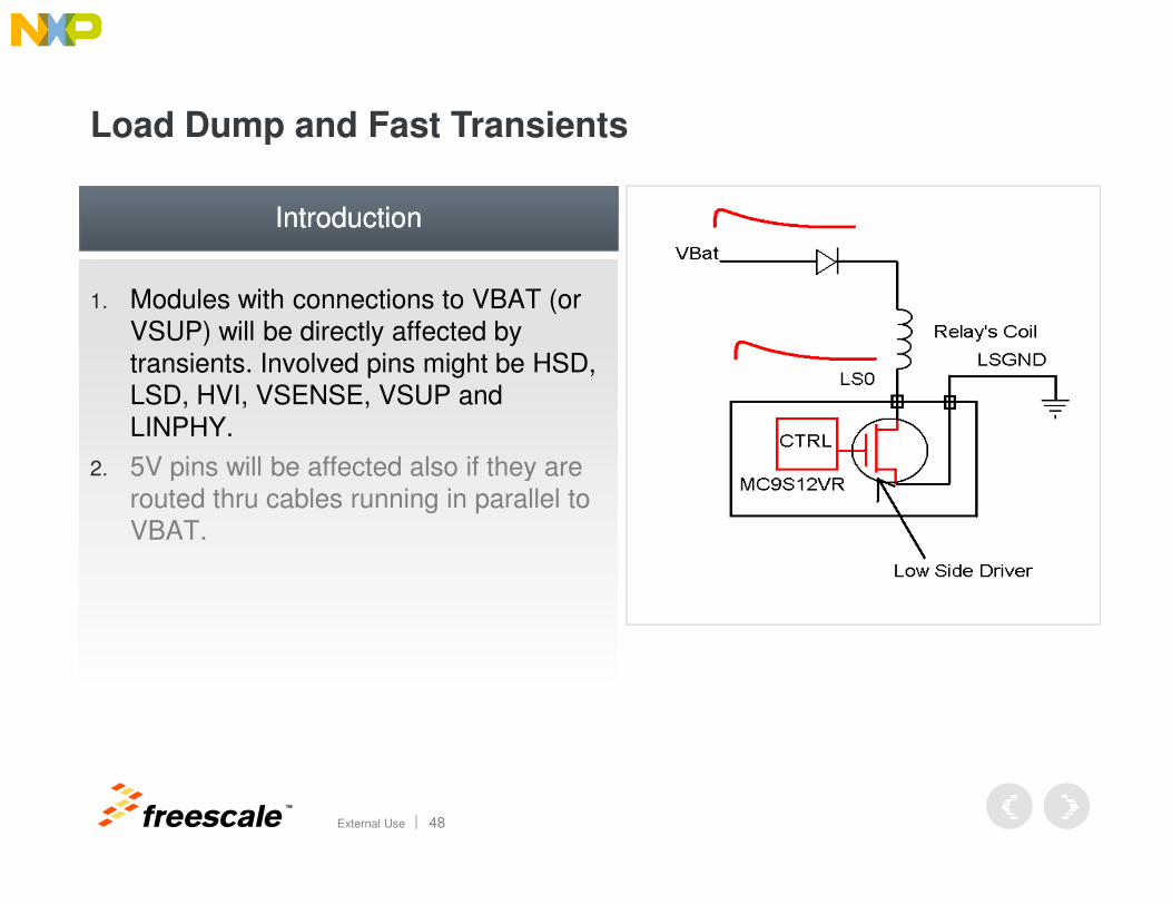
1. Modules with connections to VBAT (or VSUP) will be directly affected by transients. Involved pins might be HSD, LSD, HVI, VSENSE, VSUP and LINPHY.
5V pins will be affected also if they are
IntroductionIntroduction
TM
External Use 48
2. 5V pins will be affected also if they are routed thru cables running in parallel to VBAT.
Load Dump and Fast Transients
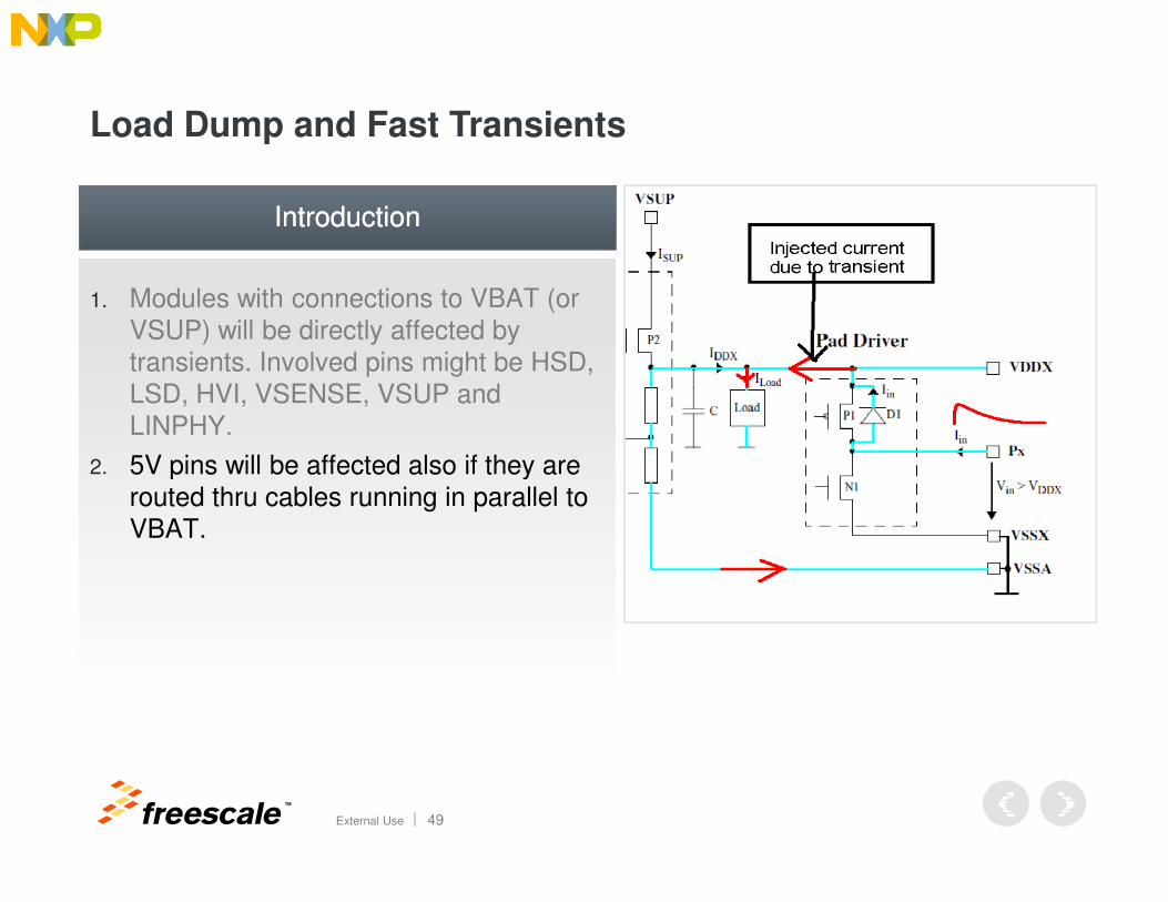
1. Modules with connections to VBAT (or VSUP) will be directly affected by transients. Involved pins might be HSD, LSD, HVI, VSENSE, VSUP and LINPHY.
5V pins will be affected also if they are
IntroductionIntroduction
TM
External Use 49
2. 5V pins will be affected also if they are routed thru cables running in parallel to VBAT.
Load Dump and Fast Transients
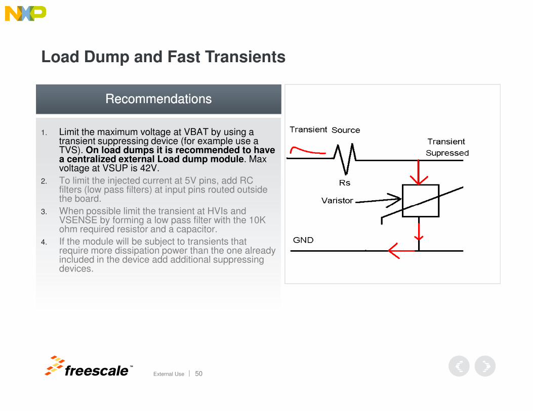
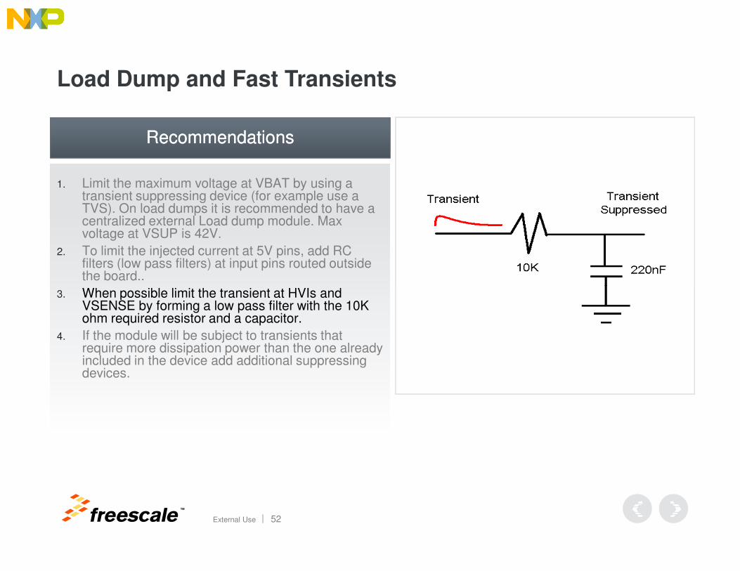
1. Limit the maximum voltage at VBAT by using a transient suppressing device (for example use a TVS). On load dumps it is recommended to have a centralized external Load dump module. Max voltage at VSUP is 42V.
2. To limit the injected current at 5V pins, add RC filters (low pass filters) at input pins routed outside the board.
When possible limit the transient at HVIs and
RecommendationsRecommendations
TM
External Use 50
3. When possible limit the transient at HVIs and VSENSE by forming a low pass filter with the 10K ohm required resistor and a capacitor.
4. If the module will be subject to transients that require more dissipation power than the one already included in the device add additional suppressing devices.
Load Dump and Fast Transients
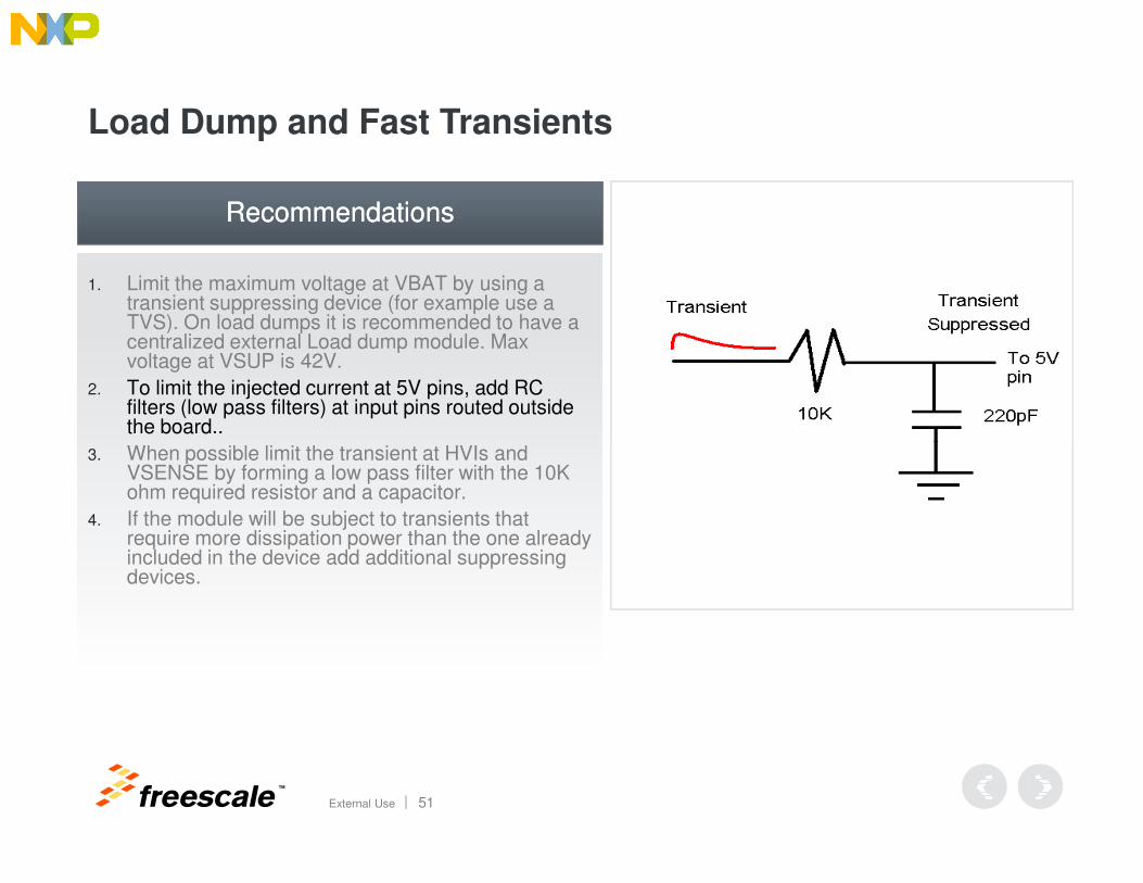
1. Limit the maximum voltage at VBAT by using a transient suppressing device (for example use a TVS). On load dumps it is recommended to have a centralized external Load dump module. Max voltage at VSUP is 42V.
2. To limit the injected current at 5V pins, add RC filters (low pass filters) at input pins routed outside the board..
When possible limit the transient at HVIs and
RecommendationsRecommendations
TM
External Use 51
3. When possible limit the transient at HVIs and VSENSE by forming a low pass filter with the 10K ohm required resistor and a capacitor.
4. If the module will be subject to transients that require more dissipation power than the one already included in the device add additional suppressing devices.
Load Dump and Fast Transients
1. Limit the maximum voltage at VBAT by using a transient suppressing device (for example use a TVS). On load dumps it is recommended to have a centralized external Load dump module. Max voltage at VSUP is 42V.
2. To limit the injected current at 5V pins, add RC filters (low pass filters) at input pins routed outside the board..
When possible limit the transient at HVIs and
RecommendationsRecommendations
TM
External Use 52
3. When possible limit the transient at HVIs and VSENSE by forming a low pass filter with the 10K ohm required resistor and a capacitor.
4. If the module will be subject to transients that require more dissipation power than the one already included in the device add additional suppressing devices.

Load Dump and Fast Transients
1. Limit the maximum voltage at VBAT by using a transient suppressing device (for example use a TVS). On load dumps it is recommended to have a centralized external Load dump module. Max voltage at VSUP is 42V.
2. To limit the injected current at 5V pins, add RC filters (low pass filters) at input pins routed outside the board..
When possible limit the transient at HVIs and
RecommendationsRecommendations
TM
External Use 53
3. When possible limit the transient at HVIs and VSENSE by forming a low pass filter with the 10K ohm required resistor and a capacitor.
4. If the module will be subject to transients that require more dissipation power than the one already included in the device add additional suppressing devices.
TM
External Use 54
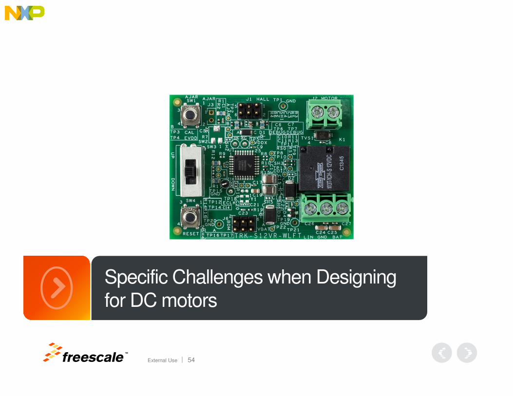
Specific Challenges when Designing for DC motors
Mid Freq. Transients During the Motor Activation
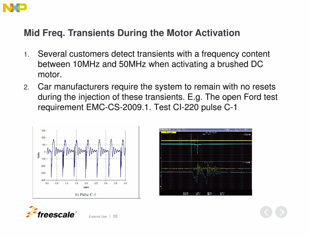
1. Several customers detect transients with a frequency content between 10MHz and 50MHz when activating a brushed DC motor.
2. Car manufacturers require the system to remain with no resets during the injection of these transients. E.g. The open Ford test requirement EMC-CS-2009.1. Test CI-220 pulse C-1
TM
External Use 55
Mid Freq. Transients During the Motor Activation
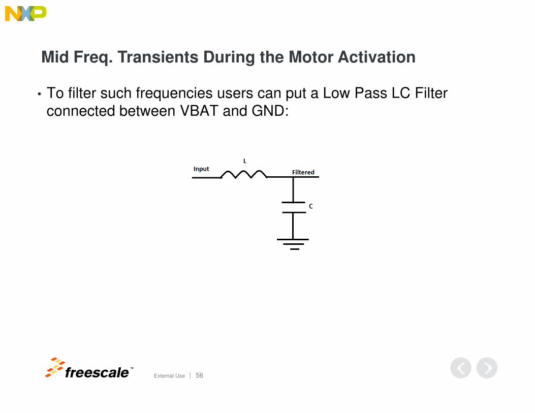
• To filter such frequencies users can put a Low Pass LC Filter connected between VBAT and GND:
TM
External Use 56
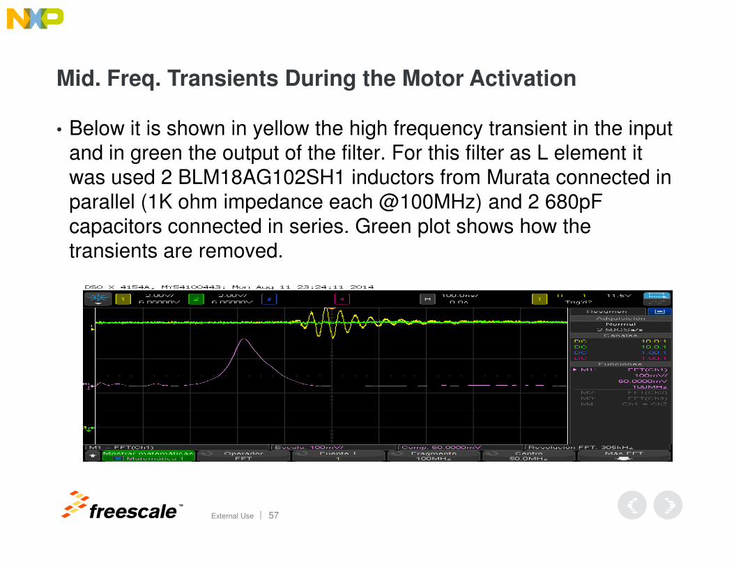
Mid. Freq. Transients During the Motor Activation
• Below it is shown in yellow the high frequency transient in the input and in green the output of the filter. For this filter as L element it was used 2 BLM18AG102SH1 inductors from Murata connected in parallel (1K ohm impedance each @100MHz) and 2 680pF capacitors connected in series. Green plot shows how the transients are removed.
TM
External Use 57

TM
External Use 58
TRK-S12VR-WLFT Reference Design Hardware Overview
TRK-S12VR-WLFT Characteristics
• S12VR Package: 32-pin LQFP
• Motor type: DC, 7A typ.
• Feedback: Hall Encoder, voltage applied at the Motor
TM
External Use 59
• PCB: 2-layer board, assembly on top side only.
2.4in x 1.9in (including demo switch and push-buttons)
BOM parts = 42 (not including headers, switch and push-buttons)
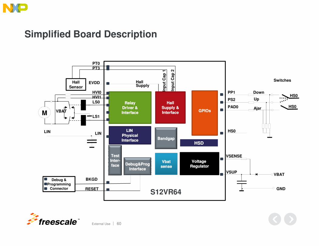
Simplified Board Description
LS0
GPIOsGPIOs
LS1M
Hall
Sensor
VBAT
Inp
ut
Cap
2
Switches
RelayRelay
Driver &Driver &
InterfaceInterface
Hall Supply
Inp
ut
Cap
1
HallHall
Supply &Supply &
InterfaceInterface
HVI0
HVI1
PP1
EVDD
PT0
PT3
PS2
PAD0
HS0
HS0
Down
Up
Ajar
TM
External Use 60
LIN
Voltage Voltage
RegulatorRegulator
HS0
VSUP
LIN LIN
PhysicalPhysical
InterfaceInterface
VbatVbat
sensesense
HSDHSD
VSENSE
VBAT
LIN
GND
Debug & Programming
Connector
BandgapBandgap
Debug&ProgDebug&Prog
InterfaceInterface
TestTest
InterInter--
faceface
BKGD
RESETS12VR64
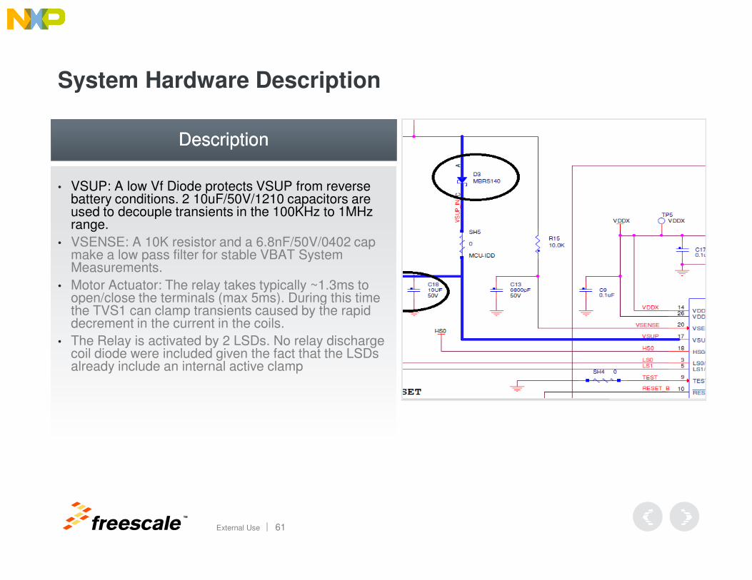
System Hardware Description
• VSUP: A low Vf Diode protects VSUP from reverse battery conditions. 2 10uF/50V/1210 capacitors are used to decouple transients in the 100KHz to 1MHz range.
• VSENSE: A 10K resistor and a 6.8nF/50V/0402 cap make a low pass filter for stable VBAT System Measurements.
• Motor Actuator: The relay takes typically ~1.3ms to open/close the terminals (max 5ms). During this time
DescriptionDescription
TM
External Use 61
• Motor Actuator: The relay takes typically ~1.3ms to open/close the terminals (max 5ms). During this time the TVS1 can clamp transients caused by the rapid decrement in the current in the coils.
• The Relay is activated by 2 LSDs. No relay discharge coil diode were included given the fact that the LSDs already include an internal active clamp
System Hardware Description
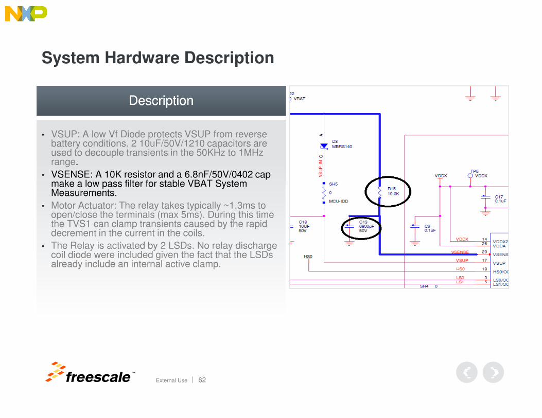
• VSUP: A low Vf Diode protects VSUP from reverse battery conditions. 2 10uF/50V/1210 capacitors are used to decouple transients in the 50KHz to 1MHz range.
• VSENSE: A 10K resistor and a 6.8nF/50V/0402 cap make a low pass filter for stable VBAT System Measurements.
• Motor Actuator: The relay takes typically ~1.3ms to open/close the terminals (max 5ms). During this time
DescriptionDescription
TM
External Use 62
• Motor Actuator: The relay takes typically ~1.3ms to open/close the terminals (max 5ms). During this time the TVS1 can clamp transients caused by the rapid decrement in the current in the coils.
• The Relay is activated by 2 LSDs. No relay discharge coil diode were included given the fact that the LSDs already include an internal active clamp.
System Hardware Description
• VSUP: A low Vf Diode protects VSUP from reverse battery conditions. 2 10uF/50V/1210 capacitors are used to decouple transients in the 50KHz to 1MHz range.
• VSENSE: A 10K resistor and a 6.8nF/50V/0402 cap make a low pass filter for stable VBAT System Measurements.
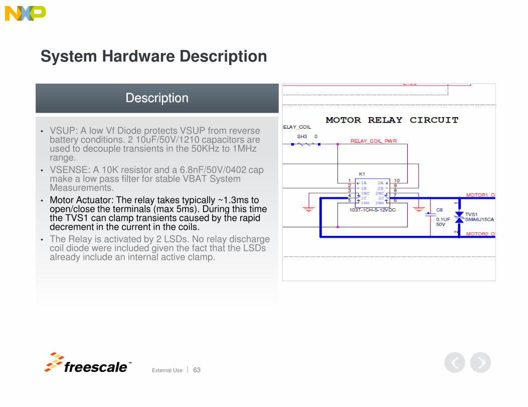
• Motor Actuator: The relay takes typically ~1.3ms to open/close the terminals (max 5ms). During this time
DescriptionDescription
TM
External Use 63
• Motor Actuator: The relay takes typically ~1.3ms to open/close the terminals (max 5ms). During this time the TVS1 can clamp transients caused by the rapid decrement in the current in the coils.
• The Relay is activated by 2 LSDs. No relay discharge coil diode were included given the fact that the LSDs already include an internal active clamp.
System Hardware Description
• VSUP: A low Vf Diode protects VSUP from reverse battery conditions. 2 10uF/50V/1210 capacitors are used to decouple transients in the 50KHz to 1MHz range.
• VSENSE: A 10K resistor and a 6.8nF/50V/0402 cap make a low pass filter for stable VBAT System Measurements.
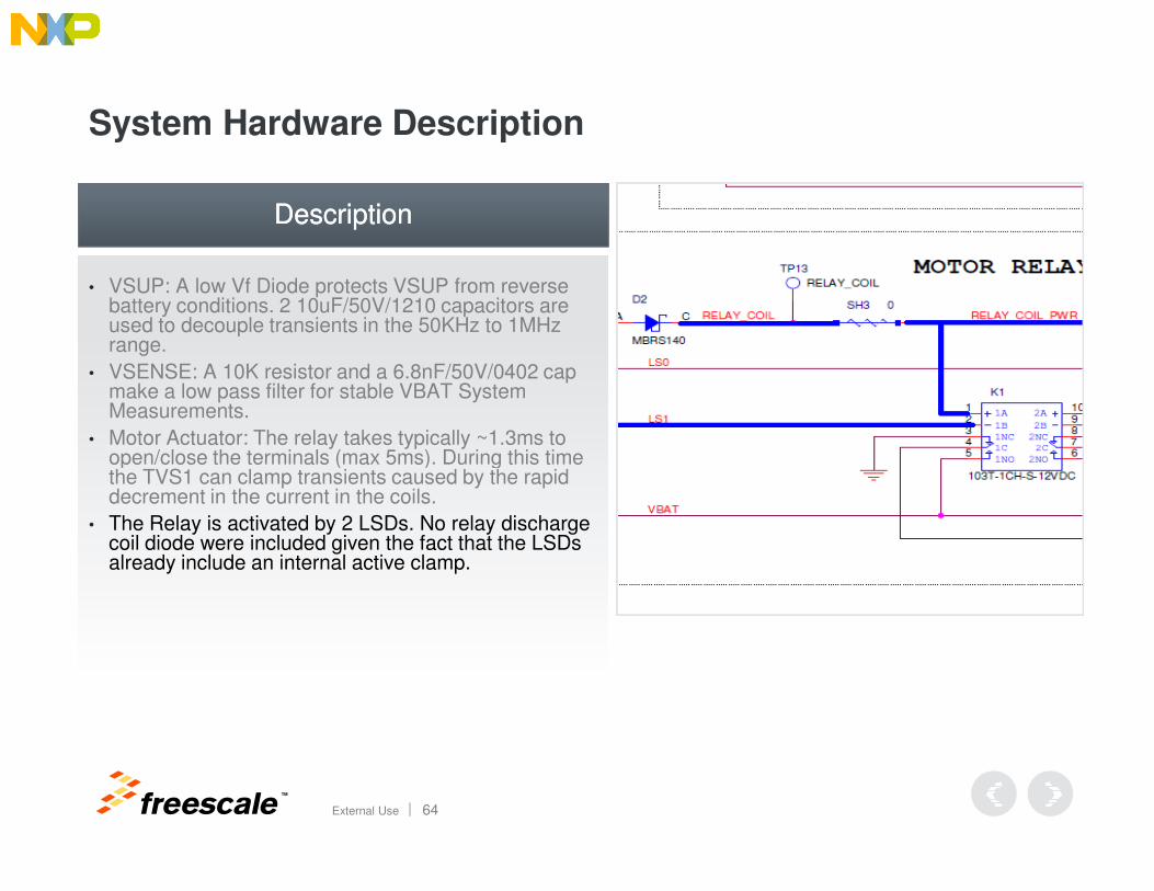
• Motor Actuator: The relay takes typically ~1.3ms to open/close the terminals (max 5ms). During this time
DescriptionDescription
TM
External Use 64
• Motor Actuator: The relay takes typically ~1.3ms to open/close the terminals (max 5ms). During this time the TVS1 can clamp transients caused by the rapid decrement in the current in the coils.
• The Relay is activated by 2 LSDs. No relay discharge coil diode were included given the fact that the LSDs already include an internal active clamp.
System Hardware Description
DescriptionDescription
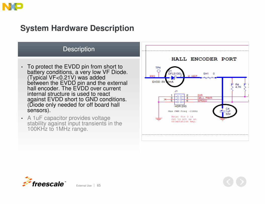
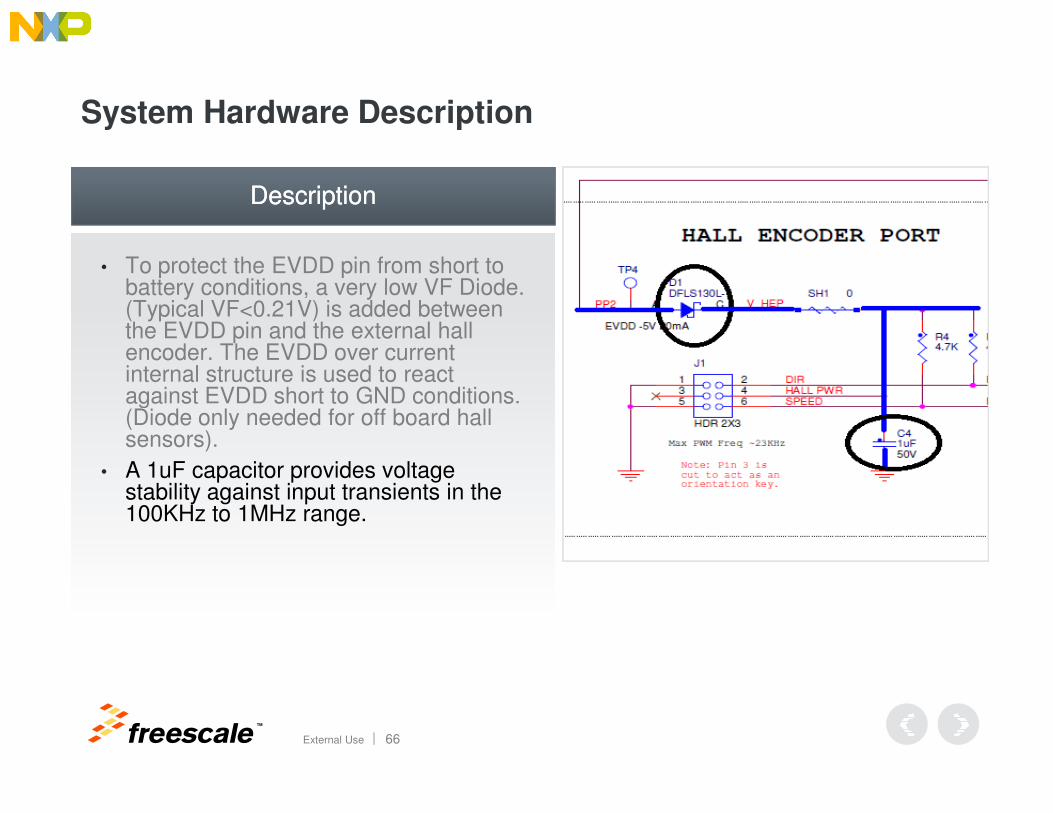
• To protect the EVDD pin from short to battery conditions, a very low VF Diode.(Typical VF<0.21V) was added between the EVDD pin and the external hall encoder. The EVDD over current internal structure is used to react against EVDD short to GND conditions. (Diode only needed for off board hall
TM
External Use 65
against EVDD short to GND conditions. (Diode only needed for off board hall sensors).
• A 1uF capacitor provides voltage stability against input transients in the 100KHz to 1MHz range.
System Hardware Description
DescriptionDescription
• To protect the EVDD pin from short to battery conditions, a very low VF Diode. (Typical VF<0.21V) is added between the EVDD pin and the external hall encoder. The EVDD over current internal structure is used to react against EVDD short to GND conditions. (Diode only needed for off board hall
TM
External Use 66
against EVDD short to GND conditions. (Diode only needed for off board hall sensors).
• A 1uF capacitor provides voltage stability against input transients in the 100KHz to 1MHz range.
System Hardware Description
DescriptionDescription
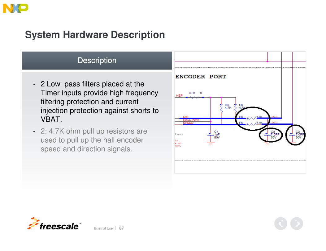
• 2 Low pass filters placed at the Timer inputs provide high frequency filtering protection and current injection protection against shorts to VBAT.
TM
External Use 67
• 2: 4.7K ohm pull up resistors are used to pull up the hall encoder speed and direction signals.
System Hardware Description
DescriptionDescription
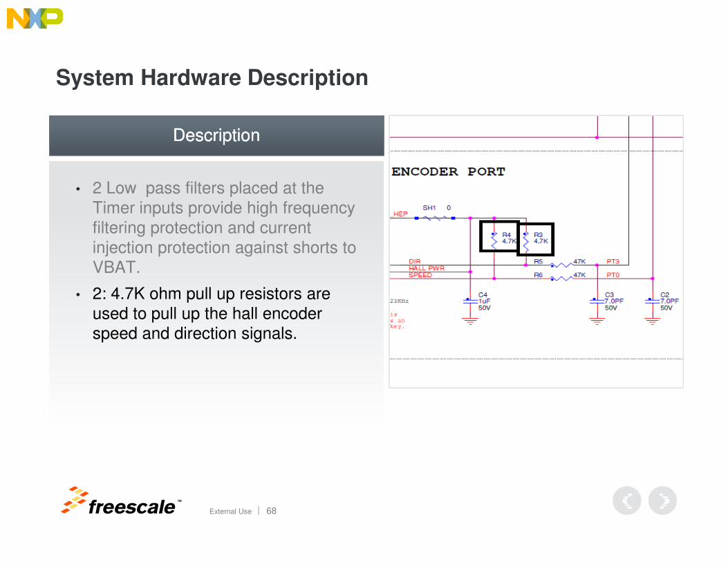
• 2 Low pass filters placed at the Timer inputs provide high frequency filtering protection and current injection protection against shorts to VBAT.
TM
External Use 68
• 2: 4.7K ohm pull up resistors are used to pull up the hall encoder speed and direction signals.
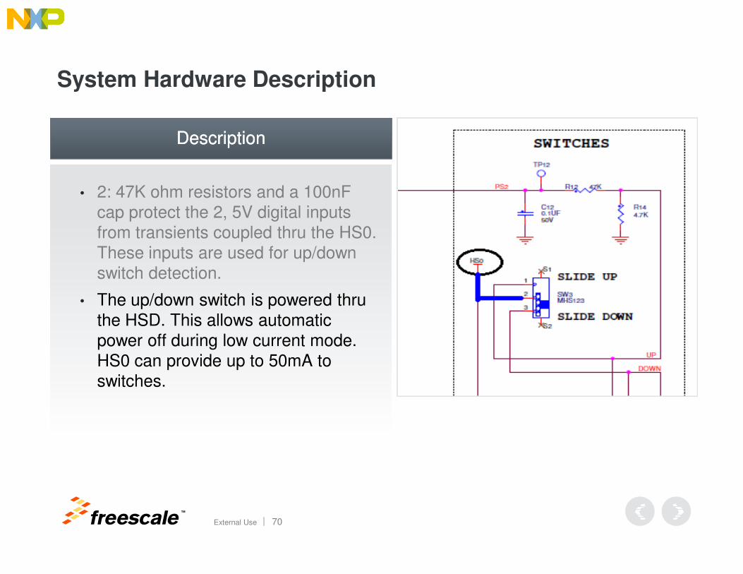
System Hardware Description
DescriptionDescription
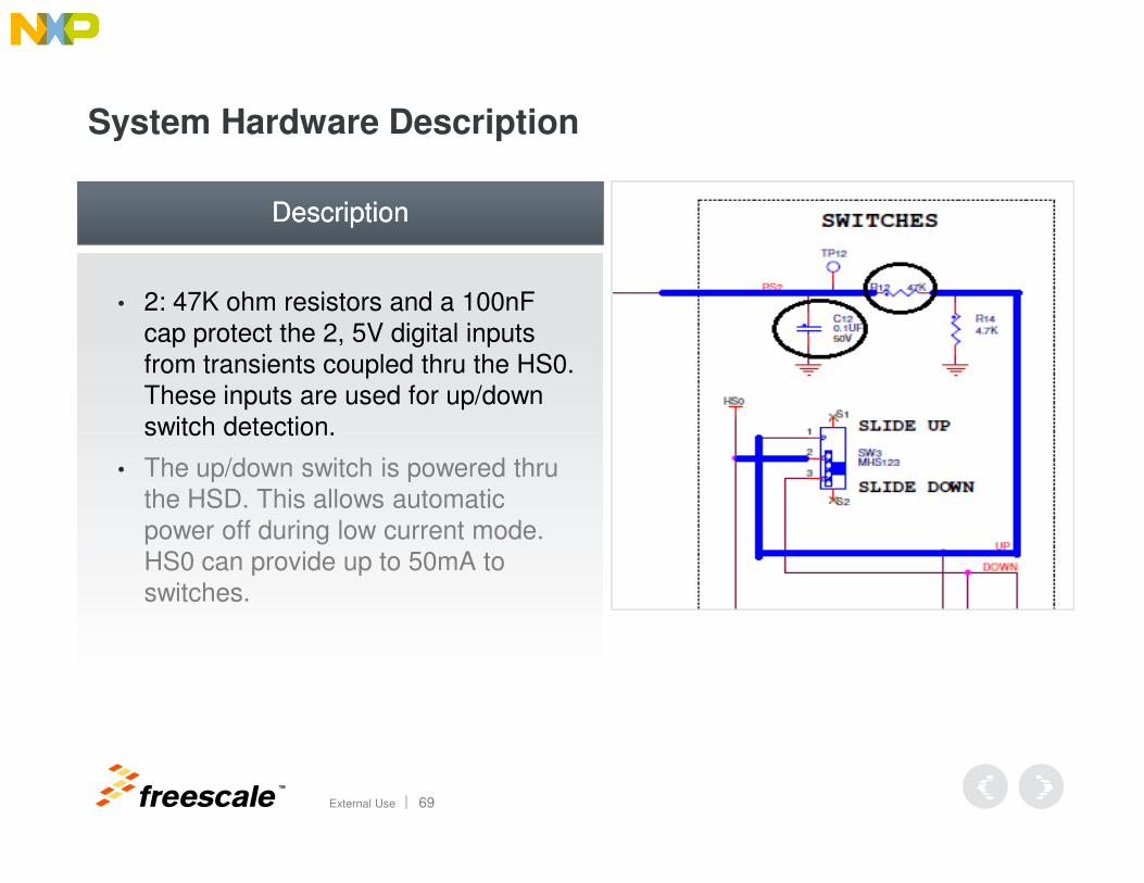
• 2: 47K ohm resistors and a 100nF cap protect the 2, 5V digital inputs from transients coupled thru the HS0. These inputs are used for up/down switch detection.
TM
External Use 69
• The up/down switch is powered thru the HSD. This allows automatic power off during low current mode. HS0 can provide up to 50mA to switches.
System Hardware Description
DescriptionDescription
• 2: 47K ohm resistors and a 100nF cap protect the 2, 5V digital inputs from transients coupled thru the HS0. These inputs are used for up/down switch detection.
TM
External Use 70
• The up/down switch is powered thru the HSD. This allows automatic power off during low current mode. HS0 can provide up to 50mA to switches.
TM
External Use 71
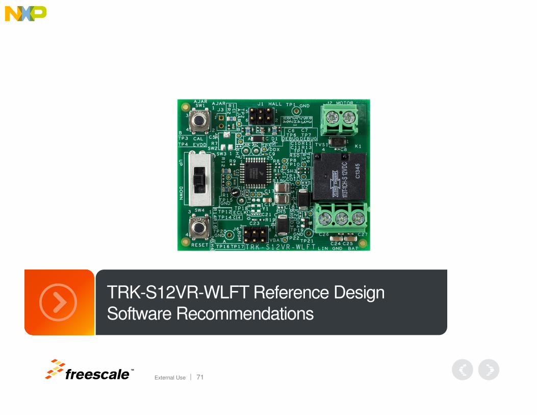
TRK-S12VR-WLFT Reference Design Software Recommendations
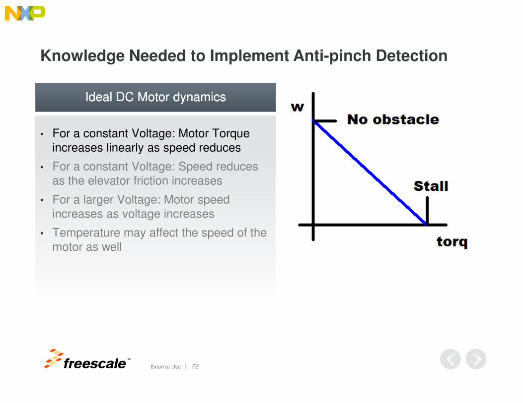
Knowledge Needed to Implement Anti-pinch Detection
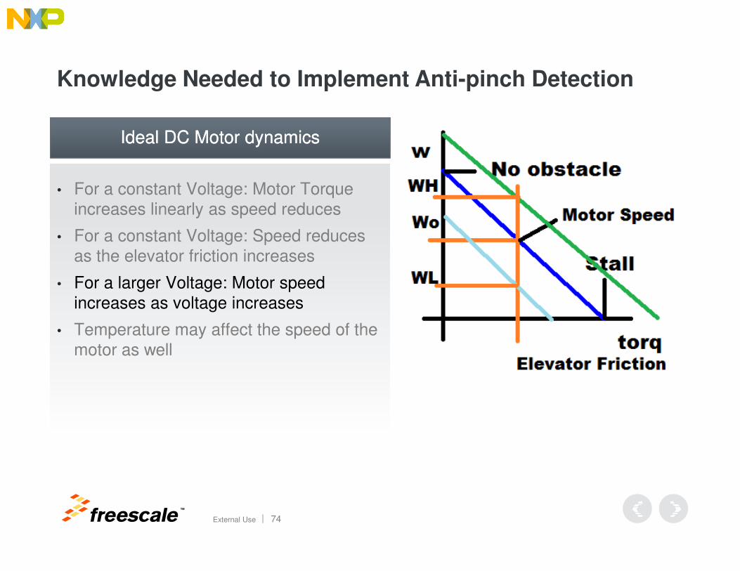
• For a constant Voltage: Motor Torque increases linearly as speed reduces
• For a constant Voltage: Speed reduces as the elevator friction increases
• For a larger Voltage: Motor speed
Ideal DC Motor dynamicsIdeal DC Motor dynamics
TM
External Use 72
• For a larger Voltage: Motor speed increases as voltage increases
• Temperature may affect the speed of the motor as well
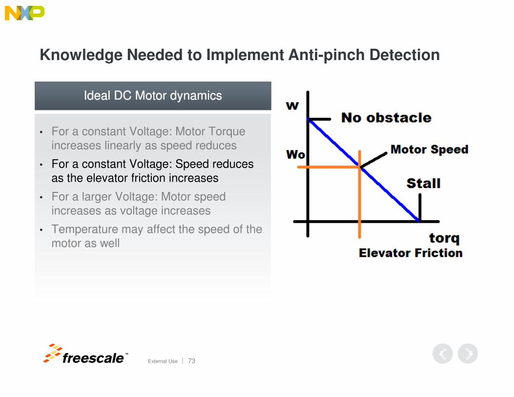
Knowledge Needed to Implement Anti-pinch Detection
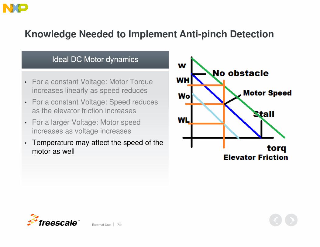
• For a constant Voltage: Motor Torque increases linearly as speed reduces
• For a constant Voltage: Speed reduces as the elevator friction increases
• For a larger Voltage: Motor speed
Ideal DC Motor dynamicsIdeal DC Motor dynamics
TM
External Use 73
• For a larger Voltage: Motor speed increases as voltage increases
• Temperature may affect the speed of the motor as well
Knowledge Needed to Implement Anti-pinch Detection
• For a constant Voltage: Motor Torque increases linearly as speed reduces
• For a constant Voltage: Speed reduces as the elevator friction increases
• For a larger Voltage: Motor speed
Ideal DC Motor dynamicsIdeal DC Motor dynamics
TM
External Use 74
• For a larger Voltage: Motor speed increases as voltage increases
• Temperature may affect the speed of the motor as well
Knowledge Needed to Implement Anti-pinch Detection
• For a constant Voltage: Motor Torque increases linearly as speed reduces
• For a constant Voltage: Speed reduces as the elevator friction increases
• For a larger Voltage: Motor speed
Ideal DC Motor dynamicsIdeal DC Motor dynamics
TM
External Use 75
• For a larger Voltage: Motor speed increases as voltage increases
• Temperature may affect the speed of the motor as well
Knowledge Needed to Implement Anti-pinch Detection
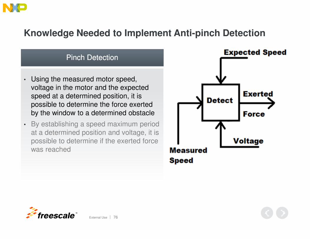
• Using the measured motor speed, voltage in the motor and the expected speed at a determined position, it is possible to determine the force exerted by the window to a determined obstacle
Pinch DetectionPinch Detection
TM
External Use 76
• By establishing a speed maximum period at a determined position and voltage, it is possible to determine if the exerted force was reached
Knowledge Needed to Implement Anti-pinch Detection
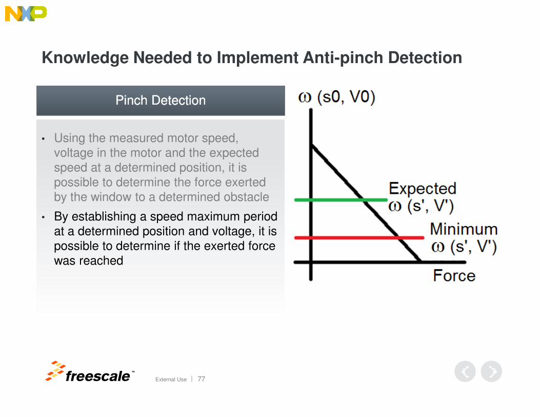
• Using the measured motor speed, voltage in the motor and the expected speed at a determined position, it is possible to determine the force exerted by the window to a determined obstacle
Pinch DetectionPinch Detection
TM
External Use 77
• By establishing a speed maximum period at a determined position and voltage, it is possible to determine if the exerted force was reached
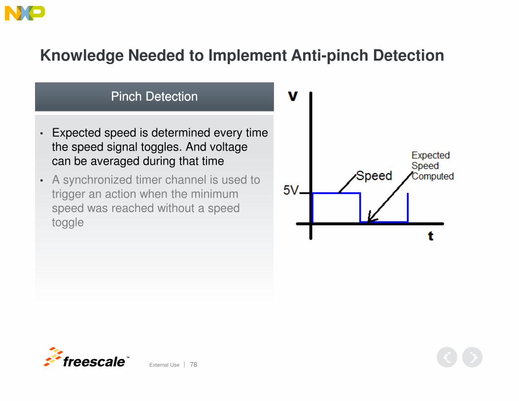
Knowledge Needed to Implement Anti-pinch Detection
• Expected speed is determined every time the speed signal toggles. And voltage can be averaged during that time
• A synchronized timer channel is used to trigger an action when the minimum
Pinch DetectionPinch Detection
TM
External Use 78
speed was reached without a speed toggle
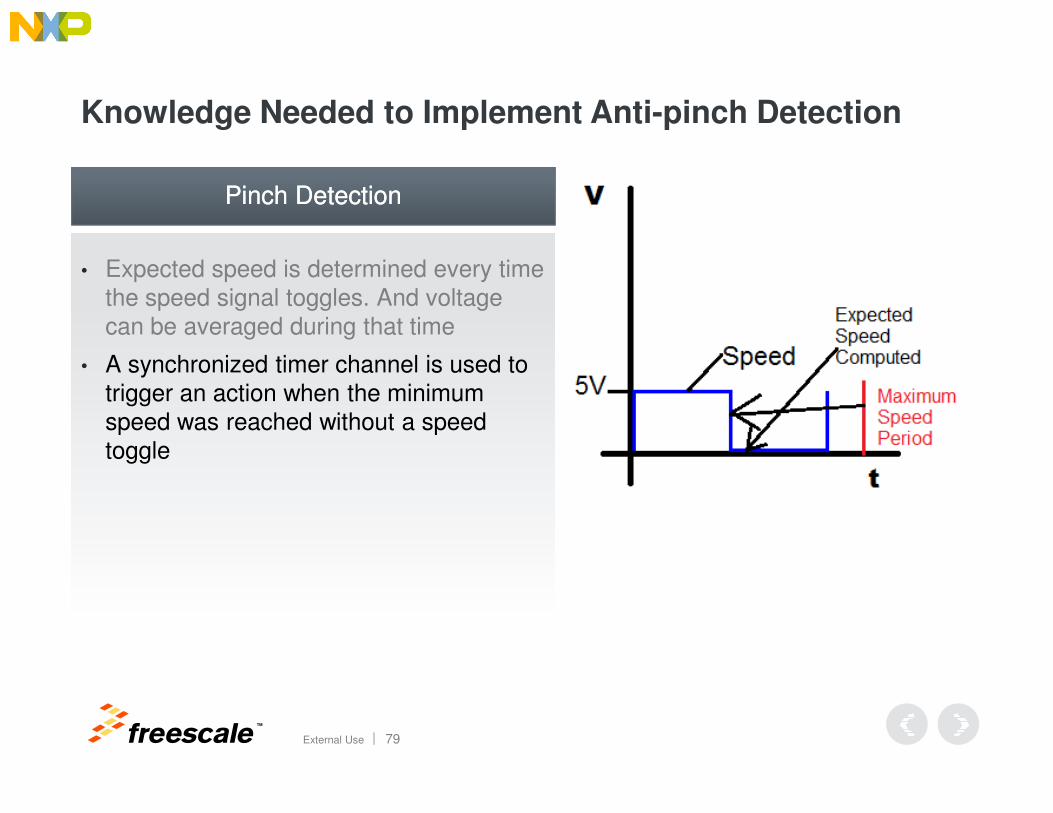
Knowledge Needed to Implement Anti-pinch Detection
• Expected speed is determined every time the speed signal toggles. And voltage can be averaged during that time
• A synchronized timer channel is used to trigger an action when the minimum
Pinch DetectionPinch Detection
TM
External Use 79
speed was reached without a speed toggle
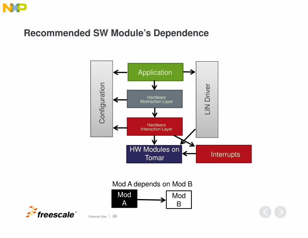
Recommended SW Module’s Dependence
Application
HardwareAbstraction Layer
Configura
tion
LIN
Driver
TM
External Use 80
HardwareInteraction Layer
Configura
tion
Mod A
Mod B
Mod A depends on Mod B
HW Modules on Tomar Interrupts
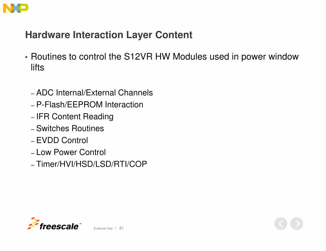
Hardware Interaction Layer Content
• Routines to control the S12VR HW Modules used in power window lifts
− ADC Internal/External Channels
− P-Flash/EEPROM Interaction
− IFR Content Reading
− Switches Routines
TM
External Use 81
− Switches Routines
− EVDD Control
− Low Power Control
− Timer/HVI/HSD/LSD/RTI/COP
Hardware Abstraction Layer Content
• Routines manipulating the HIL to perform Power Window Lifts tasks to:
− enter low power mode
− initialize calibrations
− initialize HAL
− activate the Self Reversal Routine
− handle the speed and direction
TM
External Use 82
− handle the speed and direction
− self calibrate
− perform tasks while powering down (save window position)
− control system mode based on System Power Supply Voltage
− execute tasks every 50ms.
− initialize RAM
Recommended Software Subsystems
� Speed and Direction: Tracks the window position and the measured period of the speed signal
� Voltage at the Motor: Reads the voltage at the motor up/down terminals
� Expected Speed at 12V: Uses the Speed and Direction subsystem to provide an expected speed. It depends on stored calibrations.
� Pinch Detection: Uses the information from the subsystems above to determine the deviation from the computed speed and triggers the self-reversal subsystem when a threshold is passed
TM
External Use 83
reversal subsystem when a threshold is passed
� Self-Reversal: When triggered, it controls the self reversal of the window. It either stops after a certain amount of distance is reversed or after the initial window position was reached.

TM
© 2014 Freescale Semiconductor, Inc. | External Use
www.Freescale.com
Related Documents