Sudan University of Science and Technology College of Graduate Studies Designing of Real Time Voice Scrambler / Descrambler Based on Microcontroller يم تصم مشفر/ مفك ك شفرةقي بت الحقي الصوت في الوق إيقتحكم دق م ستخدامThesis Submitted in Partial Fulfillment of the Requirement for the Degree of M.Sc. in Electronics Engineering (Computer and network Engineering) Prepared By: MOHAMMED SAAD DAOUD SULIMAN Supervisor: DR. AHMED ABDALLA MOHAMMED May 2021

Welcome message from author
This document is posted to help you gain knowledge. Please leave a comment to let me know what you think about it! Share it to your friends and learn new things together.
Transcript
Sudan University of Science and Technology
College of Graduate Studies
Designing of Real Time Voice Scrambler / Descrambler
Based on Microcontroller
ستخدام متحكم دقيق إالصوت في الوقت الحقيقي ب شفرة كمفك مشفر/ تصميم
Thesis Submitted in Partial Fulfillment of the Requirement for the
Degree of M.Sc. in Electronics Engineering (Computer and network
Engineering)
Prepared By: MOHAMMED SAAD DAOUD SULIMAN
Supervisor: DR. AHMED ABDALLA MOHAMMED
May 2021

I
Dedication
To My Beloved Mother and Father
II
Acknowledgement
First and Foremost, I have to thank my research supervisor Dr.
Ahmed Abdullah. Without his assistance and dedicated
involvement in every step throughout the process, this research
would have never been accomplished. I would like to thank you
very much for your support and understanding
.
III
Abstract
Most of voice channels used in voice terminals such as
mobile, telephone exchange are not ciphered. This makes them
vulnerable to eavesdropping and hacking. Present day securing voice
communication became an urgent need for civil and military
applications and especially for real time communication. This work
presents a real time microcontroller-based voice scrambling and
descrambling (full duplex) using 16KHz sampling frequency. Voice
scrambling / descrambling was done in frequency domain and time
domain. In frequency domain, a frequency inversion is implemented
using sinusoid wave multiplication and 8-order low pass Finite
Impulse Response filter. In time domain, a segment permutation
technique was implemented. When inputting, voice samples were
stored in memory sequentially. However, when playing the voice,
samples were read with a random sequence according to a look-up-
table. The scrambling / descrambling algorithms were verified using
MATLAB and implemented using ARDUINO DUE microcontroller.
The system was tested in real time by scrambling the voice input
from a microphone and output it through a speaker. Tests show that
the scrambled voice was not recognizable at all. Also, the
descrambled voice shows acceptable similarity with the original
voice.
IV
المستخلص
معظم القنوات المستخدمة في االتصاالت الصوتية غير مؤمنة مما يجعل الصوت عرضة
في الوقت الحاضر اصبح من الضروري المحافظة على سرية لالختراق واستراق السمع.
االتصاالت وخصوصا والمدنية العسكرية التطبيقات في الصوتية الوقت االتصاالت في
يقدم الفعلي المشروع باستخدام لآ.هذا الحقيقي الوقت في الصوت تشفير وفك لتشفير ية
في هيرتز وباالتجاهين ) االرسال واالستقبال ( .كيلو 16معالج دقيق بتردد اخذ عينات
ضرب االشارة بموجة جيبية وباستخدام مرشح بعكس الترددات للية آ نفذت ‘نطاق التردد
استخدمت ‘ في نطاق الزمن .من الدرجة الثامنة نبضية محددةذو استجابة منخفض تمرير
عند لكن تسلسليا. الذاكرة في العينات تحفظ الصوت ادخال عند . المقاطع تبديل تقنية
ليات وخوارزميات التشفير وفك آ .العينات عشوائيا وفقا لجدول بحث أقرتۥـ عرض الصوت
الالتشفير باس تحقق تم .منها الماتالب برنامج دقيق تم و تخدام معالج باستخدام تنفيذها
ديو زمن صوت دخالإب النظام .اختبراردينيو مايكرفون حقيقي في خالل واخراج من
الصوت المشفر من خالل سماعة . االختبارات وضحت ان الصوت المشفر كان غير قابل
تشفيره يبدو مشابها للصوت االصلي بشكل يز على االطالق. كما ان الصوت بعد فك يللتم
مقبول.
V
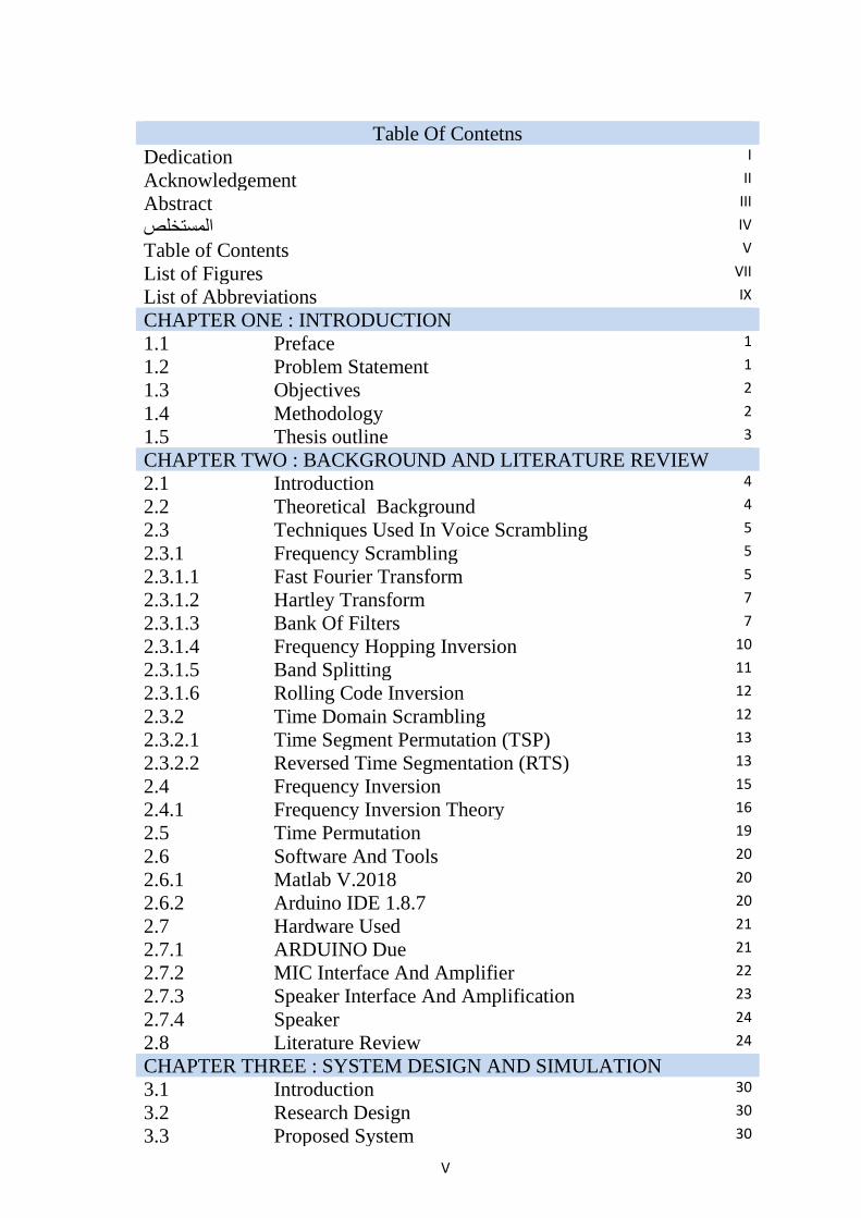
Table Of Contetns
Dedication I
Acknowledgement II
Abstract III
IV المستخلص
Table of Contents V
List of Figures VII
List of Abbreviations IX
CHAPTER ONE : INTRODUCTION
1.1 Preface 1
1.2 Problem Statement 1
1.3 Objectives 2
1.4 Methodology 2
1.5 Thesis outline 3
CHAPTER TWO : BACKGROUND AND LITERATURE REVIEW
2.1 Introduction 4
2.2 Theoretical Background 4
2.3 Techniques Used In Voice Scrambling 5
2.3.1 Frequency Scrambling 5
2.3.1.1 Fast Fourier Transform 5
2.3.1.2 Hartley Transform 7
2.3.1.3 Bank Of Filters 7
2.3.1.4 Frequency Hopping Inversion 10
2.3.1.5 Band Splitting 11
2.3.1.6 Rolling Code Inversion 12
2.3.2 Time Domain Scrambling 12
2.3.2.1 Time Segment Permutation (TSP) 13
2.3.2.2 Reversed Time Segmentation (RTS) 13
2.4 Frequency Inversion 15
2.4.1 Frequency Inversion Theory 16
2.5 Time Permutation 19
2.6 Software And Tools 20
2.6.1 Matlab V.2018 20
2.6.2 Arduino IDE 1.8.7 20
2.7 Hardware Used 21
2.7.1 ARDUINO Due 21
2.7.2 MIC Interface And Amplifier 22
2.7.3 Speaker Interface And Amplification 23
2.7.4 Speaker 24
2.8 Literature Review 24
CHAPTER THREE : SYSTEM DESIGN AND SIMULATION
3.1 Introduction 30
3.2 Research Design 30
3.3 Proposed System 30
VI
3.4 Step-1 Matlab Simulink Simulation 33
3.4.1 Test-1 33
3.4.2 Test-2 34
3.4.3 Test-3 35
3.4.4 Test-4 36
3.4.5 Test-5 38
3.5 Step-2 Matlab .M Files Simulation 38
3.5.1 Test-1 39
3.5.2 Test-2 40
3.5.3 Test-3 41
3.6 Complete Hardware System 42
CHAPTER FOUR : SYSTEM IMPLEMENTATION
4.1 Introduction 43
4.2 Design Implementation 43
4.2.1 Frequency scrambling implementation 43
4.2.1.1 Sampling frequency generation 43
4.2.1.2 Analog to Digital Convertor (ADC) 44
4.2.1.3 Digital to analog Convertor (DAC) 44
4.2.1.4 Sine wave generation 45
4.2.1.5 Filter design and implementation 45
4.2.1.6 Frequency inversion implementation 49
4.2.2 Time Permutation Implementation 50
4.2.3 ADC interrupts service routine (ISR) 51
CHAPTER FIVE : RESULTS AND DISCUSSIONS
5.1 Introduction 53
5.2 Static Tests 53
5.2.1 Test-1 Execution time calculation 53
5.2.1.1 Test-2 ADC IT RATE 54
5.2.1.2 Test 3 SINE WAVE GENERATION 55
5.2.1.3 Time scrambling implementation test 56
5.3 Arduino Real Time Test 57
CHAPTER SIX : CONCLUSION AND FUTURE WORK
6.1 Conclusion 60
6.2 Future Work 61
REFRENCES
Refrences 62
APPENDICES
Appendix A Arduino Due 64
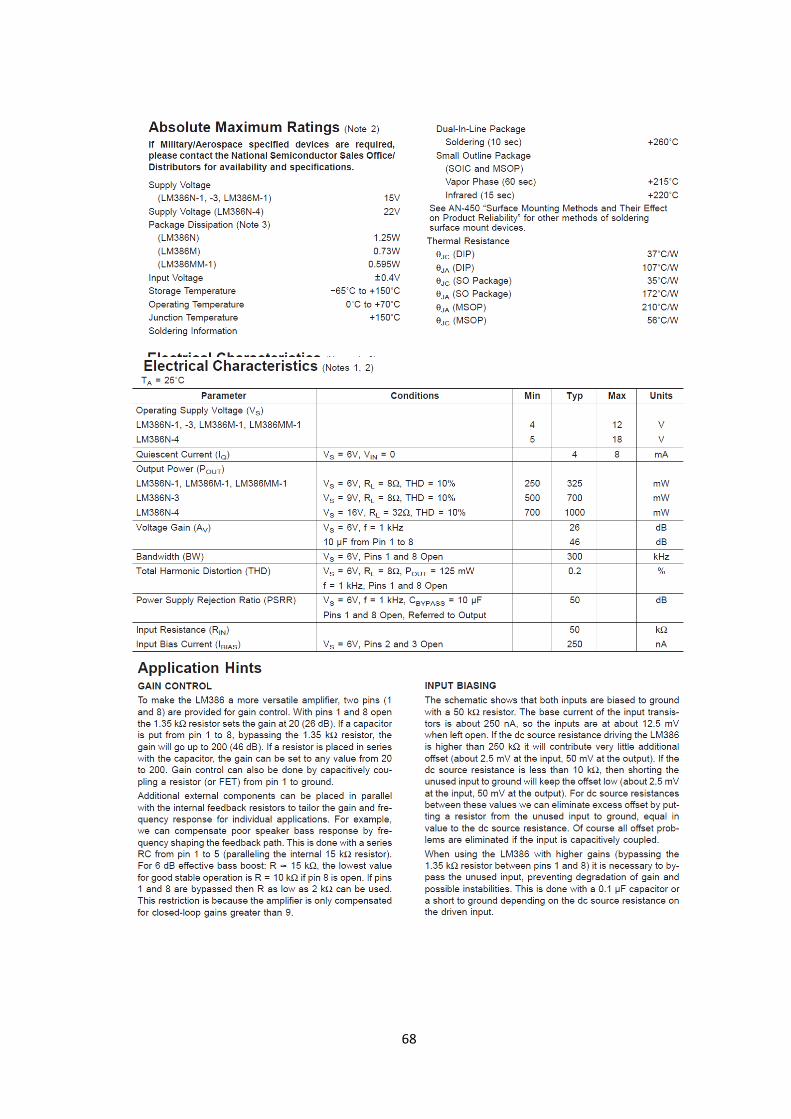
Appendix B Lm386 Low Voltage Audio Power Amplifier 67
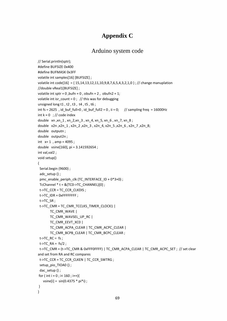
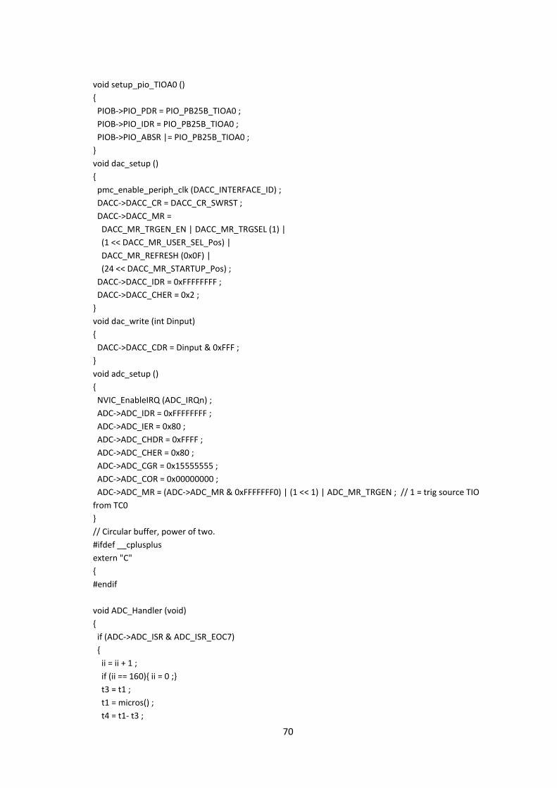
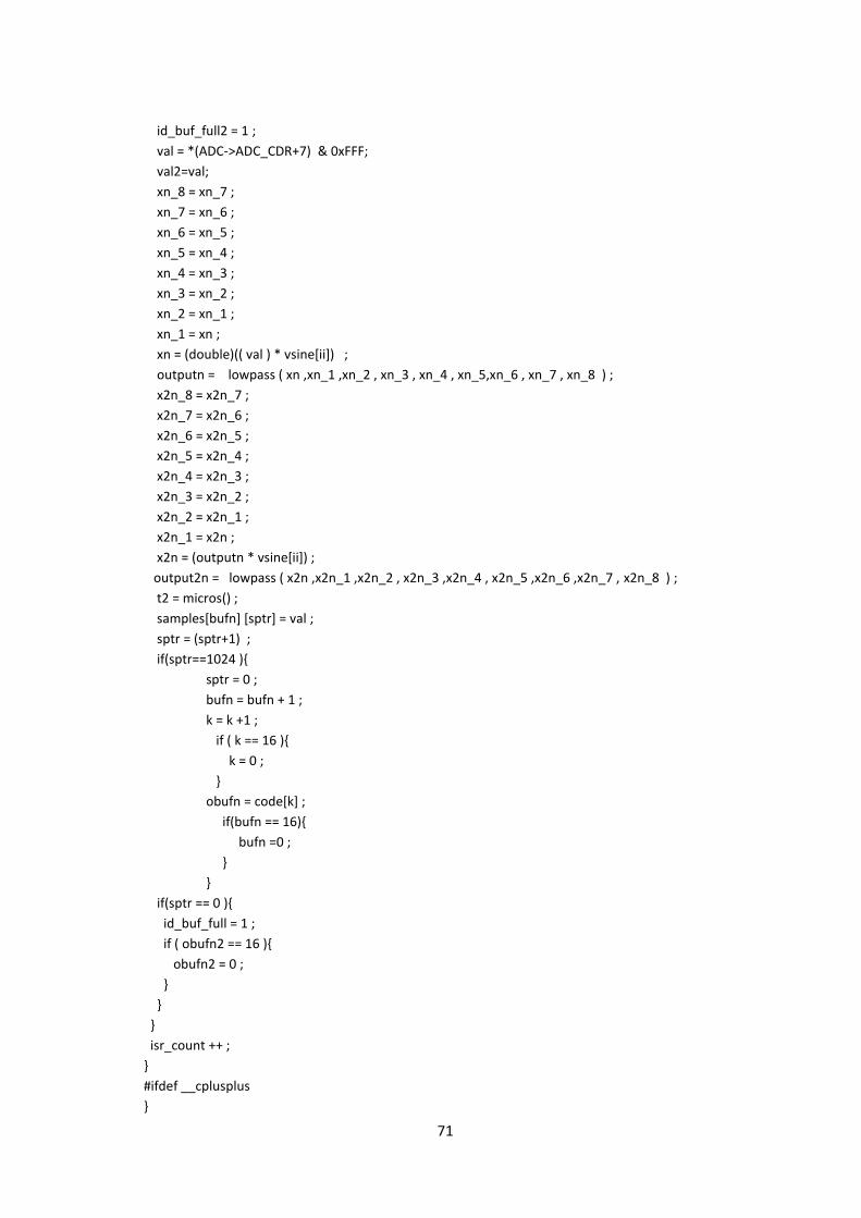
Appendix C Arduino System Code 69
Appendix D Matlab .m Code 73
VII
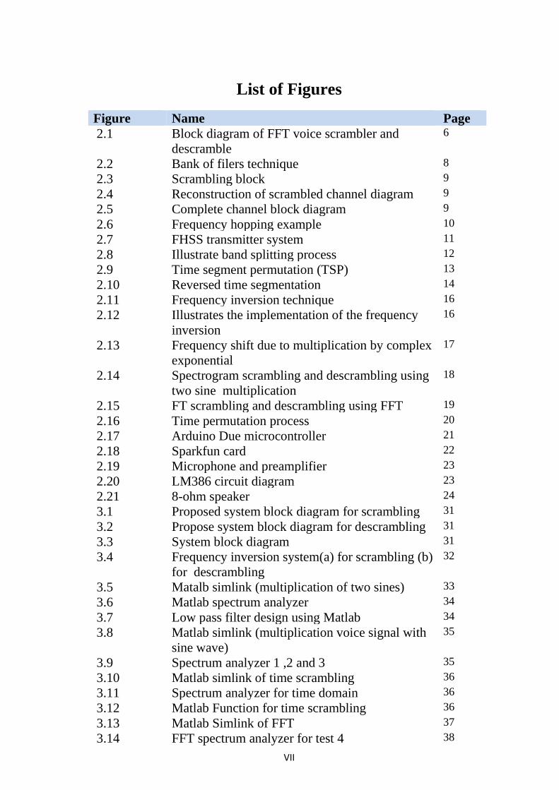
List of Figures
Figure Name Page
2.1 Block diagram of FFT voice scrambler and
descramble
6
2.2 Bank of filers technique 8
2.3 Scrambling block 9
2.4 Reconstruction of scrambled channel diagram 9
2.5 Complete channel block diagram 9
2.6 Frequency hopping example 10
2.7 FHSS transmitter system 11
2.8 Illustrate band splitting process 12
2.9 Time segment permutation (TSP) 13
2.10 Reversed time segmentation 14
2.11 Frequency inversion technique 16
2.12 Illustrates the implementation of the frequency
inversion
16
2.13 Frequency shift due to multiplication by complex
exponential
17
2.14 Spectrogram scrambling and descrambling using
two sine multiplication
18
2.15 FT scrambling and descrambling using FFT 19
2.16 Time permutation process 20
2.17 Arduino Due microcontroller 21
2.18 Sparkfun card 22
2.19 Microphone and preamplifier 23
2.20 LM386 circuit diagram 23
2.21 8-ohm speaker 24
3.1 Proposed system block diagram for scrambling 31
3.2 Propose system block diagram for descrambling 31
3.3 System block diagram 31
3.4 Frequency inversion system(a) for scrambling (b)
for descrambling
32
3.5 Matalb simlink (multiplication of two sines) 33
3.6 Matlab spectrum analyzer 34
3.7 Low pass filter design using Matlab 34
3.8 Matlab simlink (multiplication voice signal with
sine wave)
35
3.9 Spectrum analyzer 1 ,2 and 3 35
3.10 Matlab simlink of time scrambling 36
3.11 Spectrum analyzer for time domain 36
3.12 Matlab Function for time scrambling 36
3.13 Matlab Simlink of FFT 37
3.14 FFT spectrum analyzer for test 4 38
VIII
3.15 Matlab Simlink for FFT using real voice signal
input
39
3.16 Spectrum analyzer for FFT using real voice
signal
39
3.17 Spectrum analyzer for test 1 40
3.18 FFT for test 1 40
3.19 Spectrum analyzer for test 2 using IIR filter 41
3.20 FFT for test 2 using IIR filter 41
3.21 Spectrum analyzer for test 3 using FIR filter 42
3.22 FFT for test 3 using FIR filter 42
3.23 Complete hardware design 43
4.1 Sampling frequency generation 45
4.2 Filter design tools using MATLAB 47
4.3 Filter coefficients 47
4.4 IIR filter design tool using Matlab 48
4.5 IIR filter coefficients 49
4.6 Low pass filter function 50
4.7 Frequency inversion scrambling implementation 50
4.8 Frequency inversion descrambling
implementation
51
4.9 Flow chart for time permutation 52
5.1 Low pass filter implementation in Arduino 54
5.2 Scrambling and descrambling execution time 55
5.3 Sample rate check 56
5.4 Time scramble check 58
5.5 Real time test block diagram. 59
5.6 Complete hardware design 59
IX
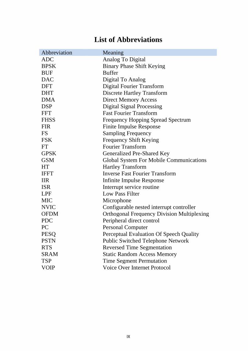
List of Abbreviations
Abbreviation Meaning
ADC Analog To Digital
BPSK Binary Phase Shift Keying
BUF Buffer
DAC Digital To Analog
DFT Digital Fourier Transform
DHT Discrete Hartley Transform
DMA Direct Memory Access
DSP Digital Signal Processing
FFT Fast Fourier Transform
FHSS Frequency Hopping Spread Spectrum
FIR Finite Impulse Response
FS Sampling Frequency
FSK Frequency Shift Keying
FT Fourier Transform
GPSK Generalized Pre-Shared Key
GSM Global System For Mobile Communications
HT Hartley Transform
IFFT Inverse Fast Fourier Transform
IIR Infinite Impulse Response
ISR Interrupt service routine
LPF Low Pass Filter
MIC Microphone
NVIC Configurable nested interrupt controller
OFDM Orthogonal Frequency Division Multiplexing
PDC Peripheral direct control
PC Personal Computer
PESQ Perceptual Evaluation Of Speech Quality
PSTN Public Switched Telephone Network
RTS Reversed Time Segmentation
SRAM Static Random Access Memory
TSP Time Segment Permutation
VOIP Voice Over Internet Protocol
CHAPTER ONE
INTRODUCTION
Chapter One Introduction
1
CHAPTER ONE
INTRODUCTION
1.1 Preface
Present day securing voice communication became an urgent need
for civil and military application and especially for real time
communication, a scrambler is a device that transposes or inverts signals
or otherwise encodes a message at the sender's side to make the message
unintelligible at a receiver not equipped with an appropriately set
descrambling device.
The security could be achieved by analog method referred as
scrambling. The characteristics of the original signal are modified in time
and frequency domain according to a given code to produce a scrambled
channel to be transmitted. While in reception the scrambled channel
received have to be descrambled to produce the original channel. The
scrambled channel has to be transmitted on voice channel bandwidth (0—
4KHz).
The security could be achieved with digital method called
encryption which is done on digital value of the signal with different
cyphering techniques. Although, very high levels of security could be
achieved but a high bandwidth is needed and imposes many restrictions in
real time implementation such as stream cipher.
1.2 Problem Statement
Most of voice channels used in voice connections such as mobile,
telephone exchange are not ciphered. This Make them vulnerable to
eavesdropping and hacking.
Chapter One Introduction
2
There is a need to guarantee end-to-end security for speech in real
time communication systems such as GSM, Voice Over Internet Protocol,
Telephone and analog Radio.
1.3 Objectives
The main objective of this work is to design, test and implement a
real time microcontroller-based voice scrambling / descrambling system
in frequency domain and time domain. Keeping the voice band without
any change (0-4KHz).
1.4 Methodology
There are two domains for voice scrambling time domain and
frequency domain. In frequency domain a frequency inversion with
variable modulation frequency while in time domain the voice is divided
into frames which are written in the memory sequentially while reading
from memory randomly to output the scrambled Voice. The number of
frames depends on microcontroller memory. To achieve real time
operation a microcontroller used for scrambling and descrambling.
Analysis and feasibility study of chosen algorithm to be
implemented in microcontroller. Analysis and estimation of execution
time for each algorithm to be executed by the microcontroller taken in to
consideration the type, clock of microcontroller, Sampling frequency and
the memory needed to be used.
Matlab implementation for the algorithms, Simulation and
execution of the algorithms in Matlab or C# to check the validity,
Robustness with different parameters used before the decision about the
final set of parameters.
Chapter One Introduction
3
Simulation Check for the algorithms with recorded voice and then
real voice.
Design and implementation of the algorithms using
microcontroller. Verification, Validation of system with testing the
system functions against the different conditions.
1.5 Thesis outline
This research consists of six chapters. Chapter One introduces the
project, problem statement, solution, objectives, and methodology of the
research. In chapter two the common scrambling techniques were
introduced with a theoretical background and literature review in the area.
In Chapter three the system design and simulation steps were discussed.
In Chapter four there is an overview of the implementation and
verification steps. Chapter five illustrates and discusses tests, verification
results after implementing the system using microcontroller. The last
chapter outlines the main conclusions and gives recommendations for
future work.
CHAPTER TWO
BACKGROUND AND LITERATURE REVIEW
Chapter Two Background and Literature Review
4
CHAPTER TWO
BACKGROUND AND LITERATUREREVIEW
2.1 Introduction
This chapter introduces the background theory and literature related
to the research conducted as well as the theoretical background of the
research.
2.2 Theoretical Background
Distinguishing Analog Scrambling from digital encryption
determining whether a specific device uses analog scrambling or digital
encryption can be difficult and confusing.
The key to distinguishing between the two is the technique used to
secure the voice. If the technique used to secure the voice only involves
some manipulation of the time or frequency characteristics of the speech
signal, the device uses analog scrambling. If the technique used to secure
the voice involves encrypting digitized voice with a conventional cipher
algorithm to yield digital cipher text, the device uses digital encryption.
[2]
The real time analog scrambling techniques implemented in this
work are.
• Frequency inversion
• Time permutation
Chapter Two Background and Literature Review
5
2.3 Techniques Used in Voice Scrambling
2.3.1 Frequency Scrambling
Most common technique used in frequency scrambling is based on
changing the frequencies of the signal in a certain way.
This section provides a review of different design methodologies
for voice scrambling in audio band with emphasizing on real time
implementation.
2.3.1.1 Fast Fourier Transform
Fast Fourier transform is used to calculate the frequency
components of the signal, the analog transform is defined by
𝑋(𝑤) = ∫ 𝑥(𝑡)𝑒−𝑗𝑤𝑡𝑑𝑡∞
−∞ (2.1)
Where X (w) is frequency domain of the signal
The digital Fourier transform (DFT) is defined by
𝑋(𝑘) = 𝑁𝑐𝑘 = ∑ 𝑥(𝑛)𝑒−𝑗2𝜋𝑘𝑛
𝑁 , 𝑘 = 0,1, … , 𝑁 − 1𝑁−1𝑛=0 (2.2)
Where X (k) is digital frequency component of the signal
The frequency resolution (the space between X (K) and X (K+1) is
given by
𝐹𝑟𝑒𝑠𝑙𝑢𝑡𝑖𝑜𝑛 =𝐹𝑆
𝑁 , 𝐹𝑆 = 𝑆𝑎𝑚𝑝𝑙𝑖𝑛𝑔 𝐹𝑟𝑒𝑞𝑢𝑒𝑛𝑐𝑦 (2.3)
For voice signal with SF =8192Hz, N=1024, the frequency
resolution = 8Hz
Noting that DFT require N*N complex multiplication (for N=1024,
number of multiplication = 1,048,576) which is so difficult to be used in
real time implementation
Chapter Two Background and Literature Review
6
To reduce the number of multiplication fast Fourier transform
algorithm (FFT) is used. Which reduce the number of multiplications to
Complex multiplication of FFT = 𝑁
2log2 𝑁 (2.4)
For N=1024, the number of complex multiplications = 3,465.
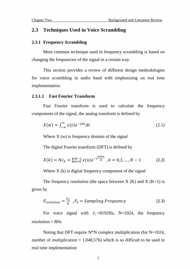
The general block diagram for voice scrambler and descramble as shown
in figure (2.1).
Figure (2.1) Block diagram of FFT voice scrambler and descrambler [5]
The basic idea of scramble block is the permutation of FFT filters
randomly or in a given sequence as defined in look up table.The
descramble block is the inverse permutation to get back the original
sequence for FFT filters. [5]
The main points for the real time implementation are
• The need for complex multiplication (Floating point) which
implies the use of dedicated DSP chip.
• The number of FFT points to be used which introduce a time
delay in scrambling and descrambling channels in addition of
frequency resolution (sampling frequency /number of
points).
Chapter Two Background and Literature Review
7
• For sampling frequency 8000Hz the processing time for
scrambling and descrambling have to less than 125
microseconds.
2.3.1.2 Hartley Transform
The Hartley transform (HT) is an integral transform closely related
to the Fourier transform (FT), but which transforms real-valued functions
to real-valued functions. It was proposed as an alternative to the Fourier
transform. The Hartley transform has the advantages of
transforming real functions to real functions (as opposed to
requiring complex numbers) and of being its own inverse.[11]
The Discrete Hartley Transform (DHT)
𝐻ℎ(𝑘Ω𝑛) =1
√𝑁∑ ℎ(𝑛𝑇)𝑁−1
𝑛−0 𝑐𝑎𝑠(𝑘Ω𝑛𝑛𝑇) (2.5)
ℎ(𝑛𝑇) ==1
√𝑁∑ 𝐻ℎ(𝑘Ω𝑛)𝑁−1
𝑘−0 𝑐𝑎𝑠(𝑘Ω𝑛𝑛𝑇) (2.6)
Ω𝑛 =2𝜋
𝑁𝑇= 𝑓𝑟𝑒𝑞𝑢𝑒𝑛𝑐𝑦 𝑟𝑒𝑠𝑜𝑙𝑢𝑡𝑖𝑜𝑛 (𝑟𝑎𝑑 𝑠−1) (2.7)
Where
𝑐𝑎𝑠(𝑤𝑡) = 𝑐𝑜𝑠(𝑤𝑡) + 𝑠𝑖𝑛(𝑤𝑡) (2.8)
As compared with Fourier transform, DHT avoids complex
arithmetic and requires half the memory storage because it requires
N log2 𝑁 real operation instead of complex operation for DFT.
Hartley transform need a real multiplication and not complex
multiplication as compared with FFT.
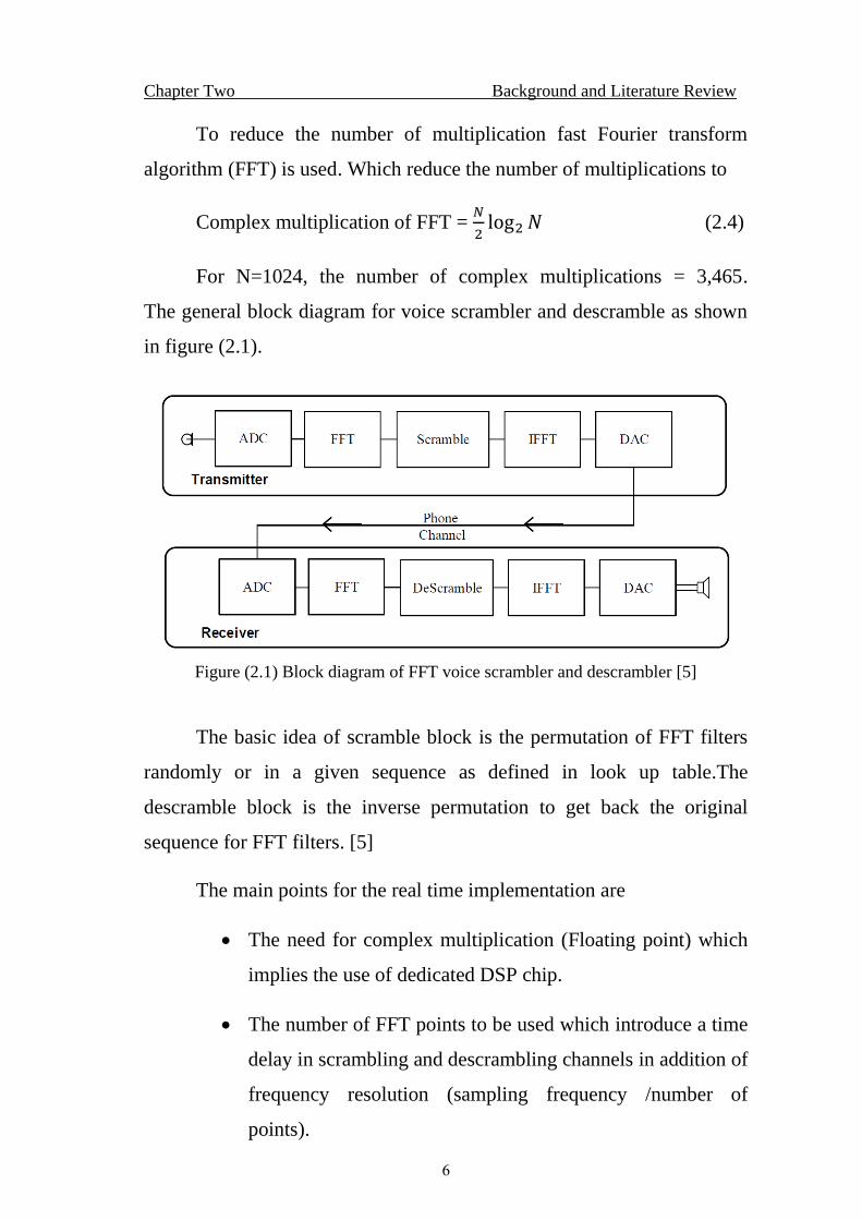
2.3.1.3 Bank of Filters
The basic idea for this technique is to separate the voice
frequency band in to different sub bands as shown in figure (2.2) below.
Chapter Two Background and Literature Review
8
Figure () Frequency sub bands
Figure (2.2) Bank of filers technique [7]
Where H (z) high pass filter, G(z) low pass filter, and (/2) down
sample by 2 (reduce sample frequency by 2) For voice example with
sampling 8000Hz, the first stage low-pass filter.
𝐹𝑐𝑢𝑡 = 1800𝐻𝑧, 𝐹𝑠𝑡𝑜𝑝 = 2000𝐻𝑧
and high- pass filter
𝐹𝑐𝑢𝑡 = 1900𝐻𝑧, 𝐹𝑝𝑎𝑠𝑠 = 2100𝐻𝑧
For the second stage sample frequency = 4000Hz
Low pass filter
𝐹𝑐𝑢𝑡 = 900𝐻𝑧, 𝐹𝑠𝑡𝑜𝑝 = 1100𝐻𝑧
High pass filter
𝐹𝑐𝑢𝑡 = 1100𝐻𝑧, 𝐹𝑝𝑎𝑠𝑠 = 1300𝐻𝑧
And so on
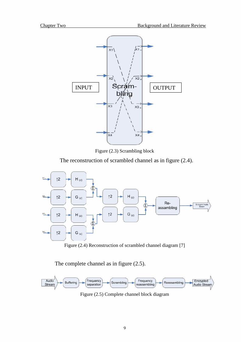
For scrambling, the position of the filter are changed as in the
figure (2.3) below.
Chapter Two Background and Literature Review
9
Figure (2.3) Scrambling block
The reconstruction of scrambled channel as in figure (2.4).
Figure (2.4) Reconstruction of scrambled channel diagram [7]
The complete channel as in figure (2.5).
Figure (2.5) Complete channel block diagram
INPUT OUTPUT
Chapter Two Background and Literature Review
10
The descrambled channel is the same as scrambled channel and the
only difference is the matrix which must be inverted to redistribute the
frequency band as in original voice.
The main challenge toward the real time implementation, the buffer
length which introduce a delay between the voice input and the output.
The time needed for wavelet transformation calculation which need
floating multiplications, and the number of level used.
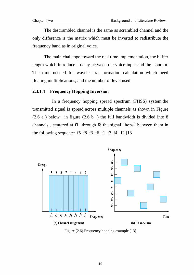
2.3.1.4 Frequency Hopping Inversion
In a frequency hopping spread spectrum (FHSS) system,the
transmitted signal is spread across multiple channels as shown in Figure
(2.6 a ) below . in figure (2.6 b ) the full bandwidth is divided into 8
channels , centered at f1 through f8 the signal “hops” between them in
the following sequence f5 f8 f3 f6 f1 f7 f4 f2.[13]
Figure (2.6) Frequency hopping example [13]
Chapter Two Background and Literature Review
11
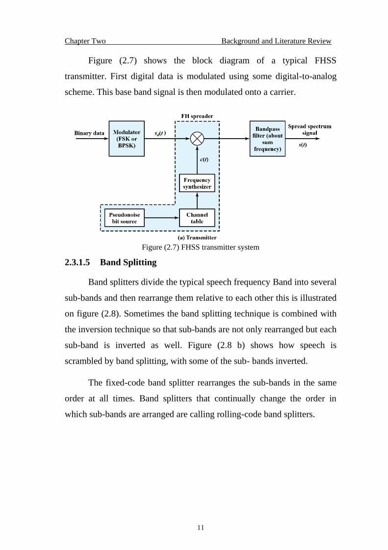
Figure (2.7) shows the block diagram of a typical FHSS
transmitter. First digital data is modulated using some digital-to-analog
scheme. This base band signal is then modulated onto a carrier.
Figure (2.7) FHSS transmitter system
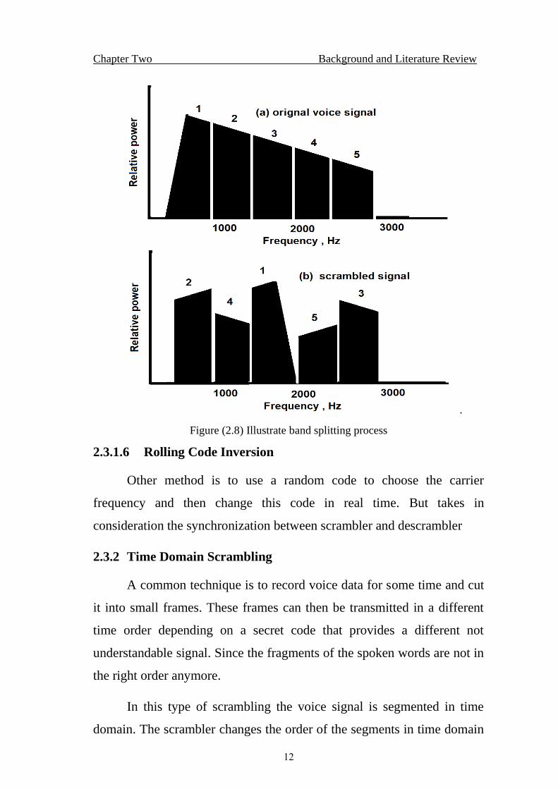
2.3.1.5 Band Splitting
Band splitters divide the typical speech frequency Band into several
sub-bands and then rearrange them relative to each other this is illustrated
on figure (2.8). Sometimes the band splitting technique is combined with
the inversion technique so that sub-bands are not only rearranged but each
sub-band is inverted as well. Figure (2.8 b) shows how speech is
scrambled by band splitting, with some of the sub- bands inverted.
The fixed-code band splitter rearranges the sub-bands in the same
order at all times. Band splitters that continually change the order in
which sub-bands are arranged are calling rolling-code band splitters.
Chapter Two Background and Literature Review
12
.
Figure (2.8) Illustrate band splitting process
2.3.1.6 Rolling Code Inversion
Other method is to use a random code to choose the carrier
frequency and then change this code in real time. But takes in
consideration the synchronization between scrambler and descrambler
2.3.2 Time Domain Scrambling
A common technique is to record voice data for some time and cut
it into small frames. These frames can then be transmitted in a different
time order depending on a secret code that provides a different not
understandable signal. Since the fragments of the spoken words are not in
the right order anymore.
In this type of scrambling the voice signal is segmented in time
domain. The scrambler changes the order of the segments in time domain
Chapter Two Background and Literature Review
13
using a given sequence (code) while the descramble try to reorder the
segments as in original voice signal.
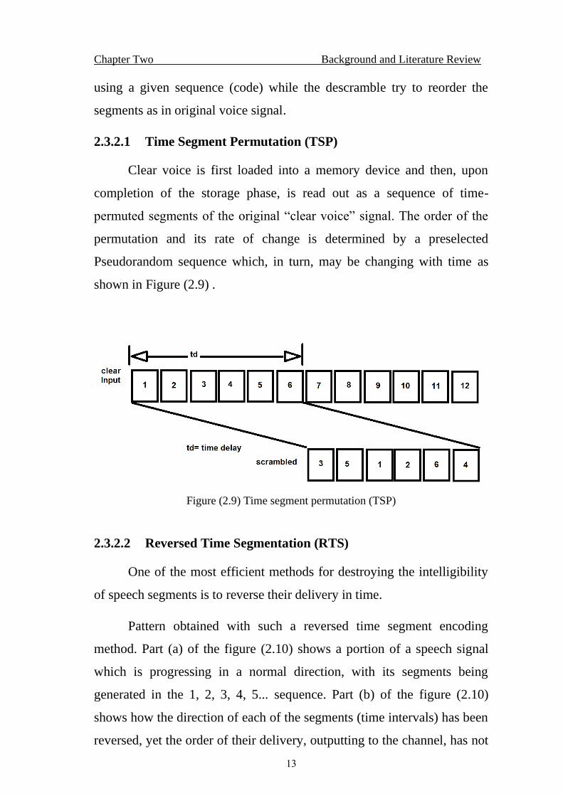
2.3.2.1 Time Segment Permutation (TSP)
Clear voice is first loaded into a memory device and then, upon
completion of the storage phase, is read out as a sequence of time-
permuted segments of the original “clear voice” signal. The order of the
permutation and its rate of change is determined by a preselected
Pseudorandom sequence which, in turn, may be changing with time as
shown in Figure (2.9) .
Figure (2.9) Time segment permutation (TSP)
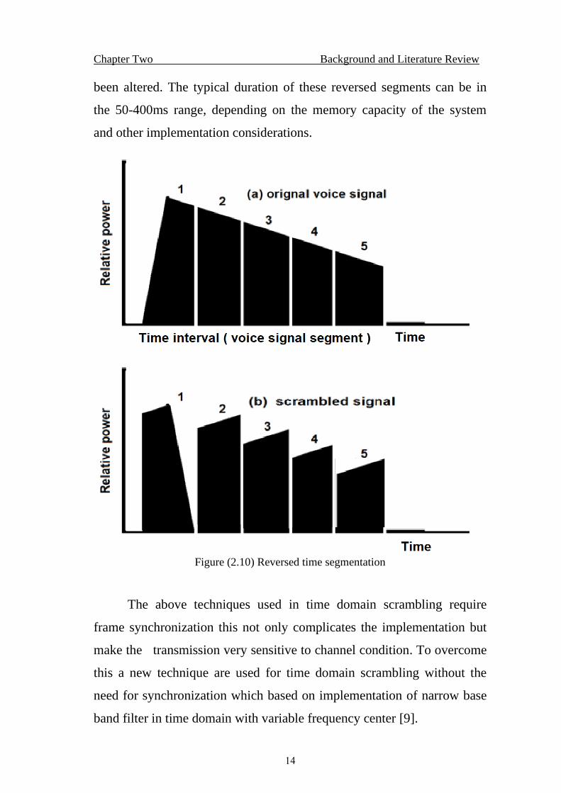
2.3.2.2 Reversed Time Segmentation (RTS)
One of the most efficient methods for destroying the intelligibility
of speech segments is to reverse their delivery in time.
Pattern obtained with such a reversed time segment encoding
method. Part (a) of the figure (2.10) shows a portion of a speech signal
which is progressing in a normal direction, with its segments being
generated in the 1, 2, 3, 4, 5... sequence. Part (b) of the figure (2.10)
shows how the direction of each of the segments (time intervals) has been
reversed, yet the order of their delivery, outputting to the channel, has not
Chapter Two Background and Literature Review
14
been altered. The typical duration of these reversed segments can be in
the 50-400ms range, depending on the memory capacity of the system
and other implementation considerations.
Figure (2.10) Reversed time segmentation
The above techniques used in time domain scrambling require
frame synchronization this not only complicates the implementation but
make the transmission very sensitive to channel condition. To overcome
this a new technique are used for time domain scrambling without the
need for synchronization which based on implementation of narrow base
band filter in time domain with variable frequency center [9].
Chapter Two Background and Literature Review
15
But these techniques process could not be implemented in
microcontroller in real time operation.
2.4 Frequency Inversion
In frequency inversion,the frequency components of the speech
signals are simply flips to up or down,thereby moving the lower part
frequency components to the upper part and moving the upper part
components to the lower part.
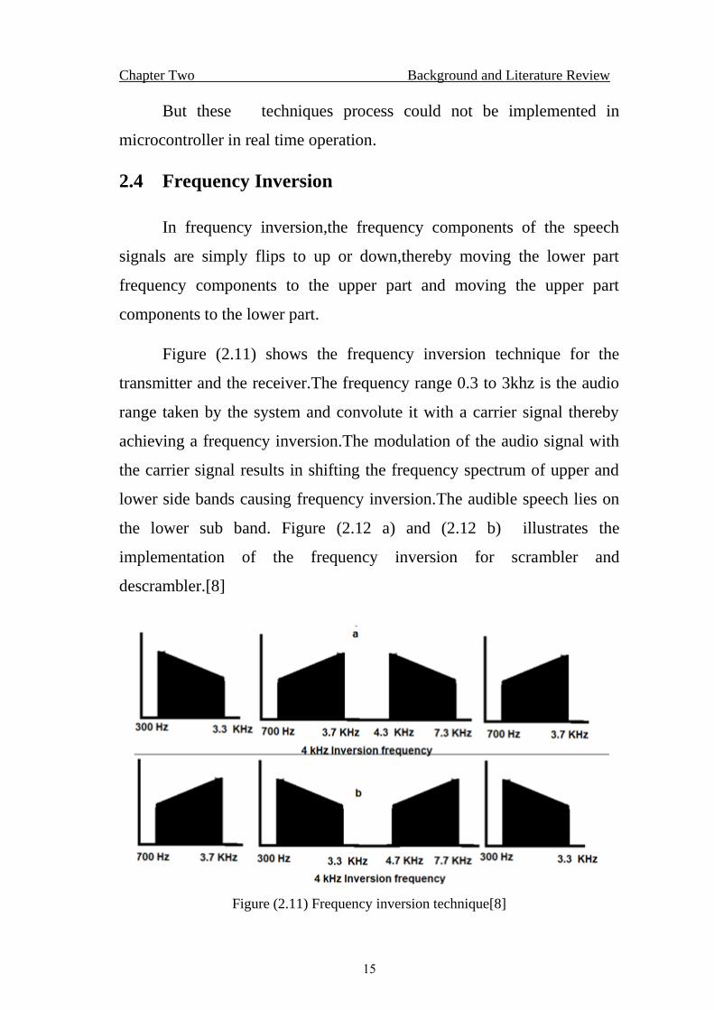
Figure (2.11) shows the frequency inversion technique for the
transmitter and the receiver.The frequency range 0.3 to 3khz is the audio
range taken by the system and convolute it with a carrier signal thereby
achieving a frequency inversion.The modulation of the audio signal with
the carrier signal results in shifting the frequency spectrum of upper and
lower side bands causing frequency inversion.The audible speech lies on
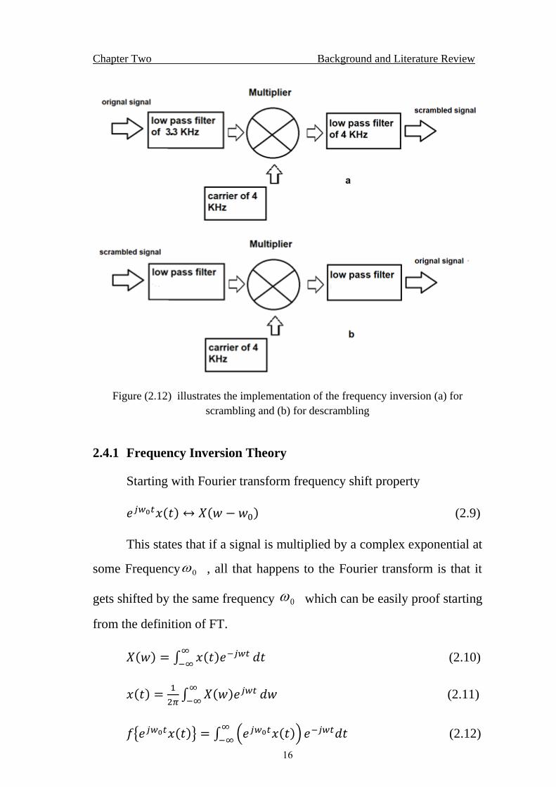
the lower sub band. Figure (2.12 a) and (2.12 b) illustrates the
implementation of the frequency inversion for scrambler and
descrambler.[8]
Figure (2.11) Frequency inversion technique[8]
Chapter Two Background and Literature Review
16
Figure (2.12) illustrates the implementation of the frequency inversion (a) for
scrambling and (b) for descrambling
2.4.1 Frequency Inversion Theory
Starting with Fourier transform frequency shift property
𝑒𝑗𝑤0𝑡𝑥(𝑡) ↔ 𝑋(𝑤 − 𝑤0) (2.9)
This states that if a signal is multiplied by a complex exponential at
some Frequency 0 , all that happens to the Fourier transform is that it
gets shifted by the same frequency 0 which can be easily proof starting
from the definition of FT.
𝑋(𝑤) = ∫ 𝑥(𝑡)𝑒−𝑗𝑤𝑡∞
−∞𝑑𝑡 (2.10)
𝑥(𝑡) =1
2𝜋∫ 𝑋(𝑤)𝑒𝑗𝑤𝑡∞
−∞𝑑𝑤 (2.11)
𝑓{𝑒𝑗𝑤0𝑡𝑥(𝑡)} = ∫ (𝑒𝑗𝑤0𝑡𝑥(𝑡))∞
−∞𝑒−𝑗𝑤𝑡𝑑𝑡 (2.12)
Chapter Two Background and Literature Review
17
= ∫ 𝑥(𝑡)∞
−∞𝑒−𝑗(𝑤−𝑤0)𝑡𝑑𝑡 (2.13)
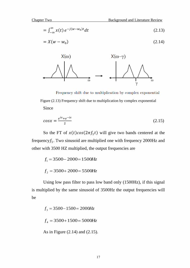
= 𝑋(𝑤 − 𝑤0) (2.14)
Figure (2.13) Frequency shift due to multiplication by complex exponential
Since
𝑐𝑜𝑠𝑥 =𝑒𝑖𝑥+𝑒−𝑖𝑥
2 (2.15)
So the FT of 𝑥(𝑡)𝑐𝑜𝑠(2𝜋𝑓1𝑡) will give two bands centered at the
frequency𝑓1. Two sinusoid are multiplied one with frequency 2000Hz and
other with 3500 HZ multiplied, the output frequencies are
Hzf 1500200035001 =−=
Hzf 5500200035002 =+=
Using low pass filter to pass low band only (1500Hz), if this signal
is multiplied by the same sinusoid of 3500Hz the output frequencies will
be
Hzf 2000150035003 =−=
Hzf 5000150035004 =+=
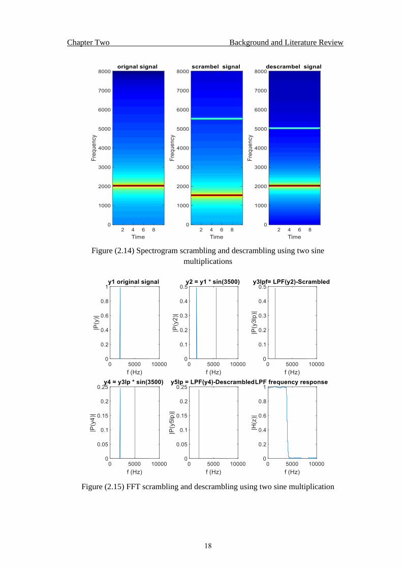
As in Figure (2.14) and (2.15).
Chapter Two Background and Literature Review
18
Figure (2.14) Spectrogram scrambling and descrambling using two sine
multiplications
Figure (2.15) FFT scrambling and descrambling using two sine multiplication
Chapter Two Background and Literature Review
19
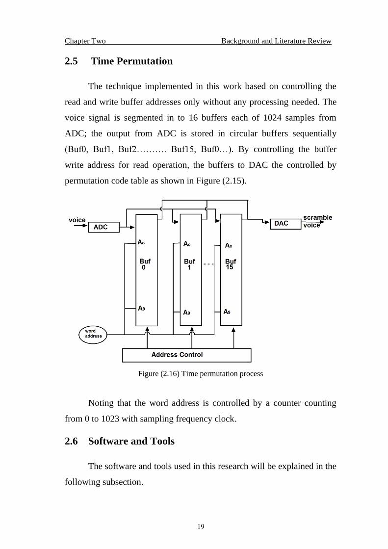
2.5 Time Permutation
The technique implemented in this work based on controlling the
read and write buffer addresses only without any processing needed. The
voice signal is segmented in to 16 buffers each of 1024 samples from
ADC; the output from ADC is stored in circular buffers sequentially
(Buf0, Buf1, Buf2………. Buf15, Buf0…). By controlling the buffer
write address for read operation, the buffers to DAC the controlled by
permutation code table as shown in Figure (2.15).
Figure (2.16) Time permutation process
Noting that the word address is controlled by a counter counting
from 0 to 1023 with sampling frequency clock.
2.6 Software and Tools
The software and tools used in this research will be explained in the
following subsection.
Chapter Two Background and Literature Review
20
2.6.1 Matlab V.2018
MATLAB Simulink is used as step one for verification and
implementation.
2.6.2 Arduino IDE 1.8.7
ARDUINO IDE 1.8.7 is used with c language for the programming
and downloading of the modules to microcontroller on ARDUINO
DUE as shown in more details in chapter 4.
2.7 Hardware Used
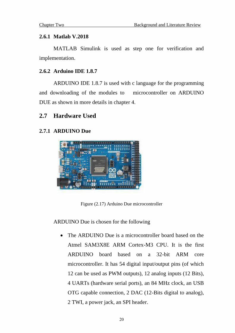
2.7.1 ARDUINO Due
Figure (2.17) Arduino Due microcontroller
ARDUINO Due is chosen for the following
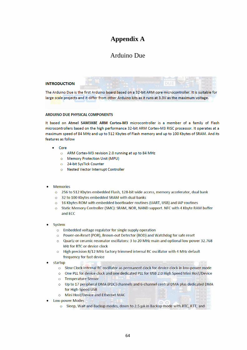
• The ARDUINO Due is a microcontroller board based on the
Atmel SAM3X8E ARM Cortex-M3 CPU. It is the first
ARDUINO board based on a 32-bit ARM core
microcontroller. It has 54 digital input/output pins (of which
12 can be used as PWM outputs), 12 analog inputs (12 Bits),
4 UARTs (hardware serial ports), an 84 MHz clock, an USB
OTG capable connection, 2 DAC (12-Bits digital to analog),
2 TWI, a power jack, an SPI header.
Chapter Two Background and Literature Review
21
• Peripheral DMA Controller (PDC) to handles data transfer
between peripherals and memory without the intervention of
the processor.
• Three timers counters modules and each of these has three
channels giving nine timer counter channels in all. In this
implementation both ADC and DAC are triggered by
channel 0 and channel 1 respectively.
• A configurable nested interrupt controller (NVIC) to deliver
industry-leading interrupt performance. The NVIC provides
up to 16 interrupt priority levels, dramatically reducing the
interrupt latency, fast execution of interrupt service routine
(ISR).
• 256 to 512 Kbytes embed Flash with 32 to 100Kbytes
SRAM with dual banks.
• 16-channel 12-bit ,1 MBPS ADC with differential input
mode and programmable gain stage.
• 2-channel 12-bit 1 MBps DAC.
• Rich libraries for programming.
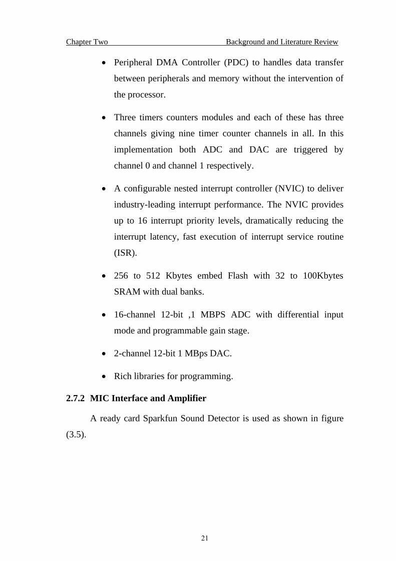
2.7.2 MIC Interface and Amplifier
A ready card Sparkfun Sound Detector is used as shown in figure
(3.5).
Chapter Two Background and Literature Review
22
Figure (2.18) Sparkfun card
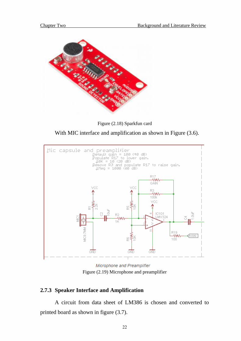
With MIC interface and amplification as shown in Figure (3.6).
Figure (2.19) Microphone and preamplifier
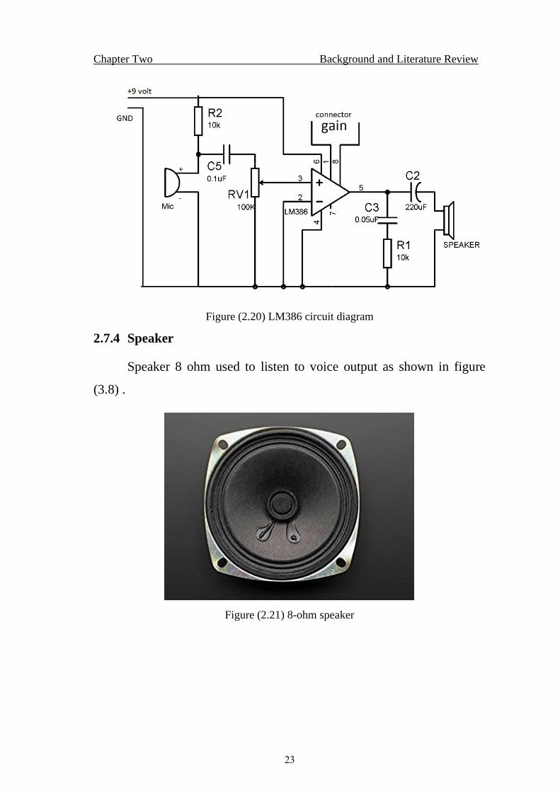
2.7.3 Speaker Interface and Amplification
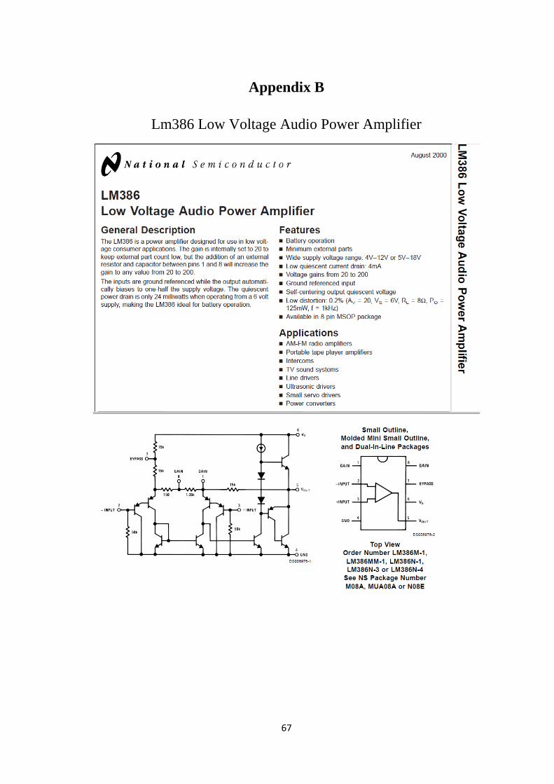
A circuit from data sheet of LM386 is chosen and converted to
printed board as shown in figure (3.7).
Chapter Two Background and Literature Review
23
Figure (2.20) LM386 circuit diagram
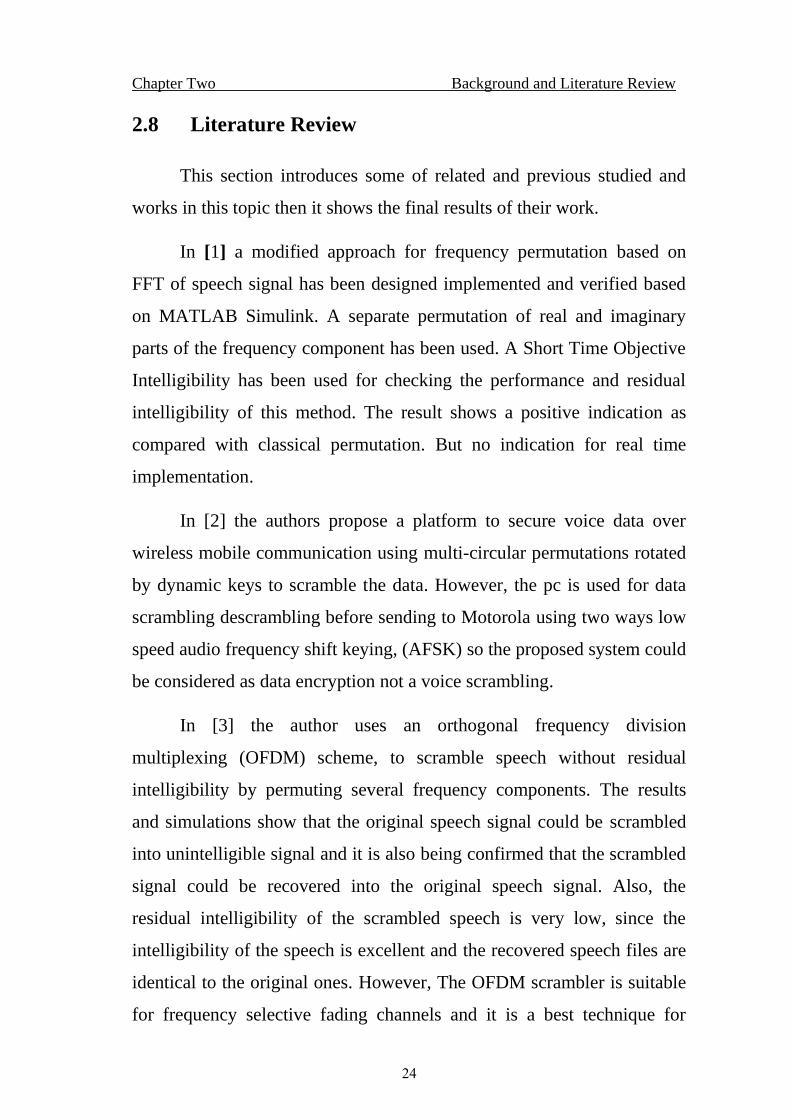
2.7.4 Speaker
Speaker 8 ohm used to listen to voice output as shown in figure
(3.8) .
Figure (2.21) 8-ohm speaker
Chapter Two Background and Literature Review
24
2.8 Literature Review
This section introduces some of related and previous studied and
works in this topic then it shows the final results of their work.
In [1] a modified approach for frequency permutation based on
FFT of speech signal has been designed implemented and verified based
on MATLAB Simulink. A separate permutation of real and imaginary
parts of the frequency component has been used. A Short Time Objective
Intelligibility has been used for checking the performance and residual
intelligibility of this method. The result shows a positive indication as
compared with classical permutation. But no indication for real time
implementation.
In [2] the authors propose a platform to secure voice data over
wireless mobile communication using multi-circular permutations rotated
by dynamic keys to scramble the data. However, the pc is used for data
scrambling descrambling before sending to Motorola using two ways low
speed audio frequency shift keying, (AFSK) so the proposed system could
be considered as data encryption not a voice scrambling.
In [3] the author uses an orthogonal frequency division
multiplexing (OFDM) scheme, to scramble speech without residual
intelligibility by permuting several frequency components. The results
and simulations show that the original speech signal could be scrambled
into unintelligible signal and it is also being confirmed that the scrambled
signal could be recovered into the original speech signal. Also, the
residual intelligibility of the scrambled speech is very low, since the
intelligibility of the speech is excellent and the recovered speech files are
identical to the original ones. However, The OFDM scrambler is suitable
for frequency selective fading channels and it is a best technique for
Chapter Two Background and Literature Review
25
providing high security in the next generation mobile communication
system
The authors in [4] provides an idea for encryption of voice signal in
wired public switched telephone network (PSTN) system as it has better
connectivity, and is noise free. The idea of the paper is to ensure advance
level of audio security using rapid time domain scrambling. The 256kbit
of ram can store 4 seconds of data considering delta modulation is done at
64kbits of data rate the double buffering initially in the transmission side
and then in the receiving device and together with additional
synchronization signals needed, however the overall signal delay will
accumulate up to 2.6 seconds. This is indeed to slow for the Full Duplex
period. Therefore, the communication used in the crypto mode is a Half-
Duplex. This operating standard of encryption mode is similar to the
walky talky with PTT (push-to-talk) button. The hardware platform is
constructed using standard AVR microcontroller (8 bits) Atmega8515
with added SRAM for temporary storage of voice.
In this paper [5] three scrambling techniques are presented and
their performances are analyzed. These methods were tested based on
some real audio signals that they were recorded in an anechoic chamber,
shifted spectrum, sub bands and sub bands and shift spectrum. However
it’s not a real time operation.
In [6] the authors propose wavelet transform scrambling system,
speech has been recorded with sampling frequency 11.025 KHz as wav
files. At the scrambler, the sample speech signal is converted into frames
with each frame containing 64 samples and then the Wavelet
Transformation is performed on each frame. After that, the transform
coefficients are permuted. The resulting scrambled speech signal is saved
in a wave file. At the descrambler, frame by frame of length 64 samples
Chapter Two Background and Literature Review
26
are descrambled and saved in wave file. The proposed system investigates
one type of Wavelet (Daubechies 4), with one level and not a real time
system operation.
In [7] fast hartly transform is used. The hartley transformed
coefficients are then given to the scrambler which scrambles the
coefficients according to the OFDM scrambling keys generated by the
algorithm process. After scrambling, inverse hartley transform is applied
to the frequency scrambled hartley coefficients, which is same as the
direct transform. The IFHT output is converted to analog by DAC and
after multiplexing with synchronization signal and training sequence it is
released to the channel. The speech signal is sampled at a rate of 8000
samples per sec. The input signal is processed over a band width of 3.1
kHz, ranges from 300-3400 Hz. The transmission channel band limited to
the range of 0-4000Hz.The 256 samples frame size results in 32ms frame
time. However, the proposed system was simulated in matlab.
In [8] the authors Presents speech security method which enables
variety of encryption operations in the combined time and frequency
spaces. The analog speech encryption operations are performed by an
important Bi-orthogonal transformation technique in order to give the
communication systems that based on using a speech signal high degree
of the security. The noisy communication channel usually accompanying
the encryption processes is studied. Different case studies were taken into
consideration, through using different types of Biorthogonal transforms.
The performance of the proposed scheme is examined through the
calculation of evaluation measure (the segmental signal to noise ratio).
The results are promising for analog speech encryption systems.
In [9] the authors present an overview of the main analog
scramblers which are, time domain, frequency domain and Encryption by
Chapter Two Background and Literature Review
27
using Pseudo-Noise Sequences. Using XOR operation of these sequences
with the speech samples makes the speech signal a noise-like signal, and
the encrypted speech signal sounds like a random noise signal. Although
The intangibility of speech signal can be reduced by removing the
correlation among the speech samples by using XOR with Pseudo-Noise
sequences, this operation will affect the voice channel properties and
could be used for data communication techniques like voice over internet
protocol.
In [10] the authors Presents a real-time frequency voice scrambler
algorithm and its Implementation in TMS 320C6X - TEXAS Instruments
DSP (Digital Signal Processor) architecture. The voice channel
cryptography system is based on a scrambled discrete Hartley Transform.
It includes large energy random components inserted into the voice
channel bandwidth. As result it's not possible to identify pauses between
words, and it is also observed that the speaker could not be identified. The
proposal uses low cost hardware architecture adapted for tactical level
security in network voice communications. Real-time experimental
results have been performing well in a variety of analog voice channels.
In [11] describes the real time implementation of frequency domain
scrambling and descrambling techniques on Texas TMS320C6711 DSP,
three techniques are implemented. frequency inversion, frequency
hopping inversion and rolling code inversion.
In [12] a band scrambler which processes only time domain
Samples are described. The band scrambler has the effect of dividing the
input signal spectrum into N sub-bands. The N sub-bands are permuted
such that the rth band is mapped onto the k.rth band modulo N, where N
is a constant of the scrambler and k is the key which is variable in the
range 2<k.<N-l.
Chapter Two Background and Literature Review
28
The authors in [13] propose time domain scrambling which does
not need synchronization. The scrambler permutes individual speech
samples rather speech segments with band pass filter process with
variable center frequency implemented in time domain the process. Made
to be equivalent to a frequency-band scrambler.
The authors in [14] describe the hardware architecture and the
signal processing algorithm of a secure telephone which can be used over
the public switched network. Using time-varying frequency-domain
scrambling, a high level of security can be achieved, with no residual
intelligibility. By means of the DFT filter banks implemented by the FFT
and polyphase networks; the entire signal processing for a full duplex
conversation can be performed with a single TMS320C25 digital signal
processor. The complete scrambler fits inside a standard telephone set
unit.
The authors in [15] Present FFT scrambling method based on the
manipulations of the Fast Fourier Transform (FFT) coefficients of speech
is one of the analog speech scramblers which realize high-level security
and excellent descrambled speech quality. It is not clear, however, how
the descrambled speech quality and synchronization performance are
affected by transmission impairments. This paper analyzes the effects of
transmission impairments on the descrambled speech quality by computer
simulations and provides a guide for the system design. Then practical
methods to cope with the effect of transmission impairments are
proposed. Based on the results of the simulations, experimental
scramblers are developed using general-purpose DSP's (Digital Signal
Processors). The system configuration and the result of the performance
evaluation tests are shown. The experimental scramblers are equipped
with an automatic equalizer for group delay and amplitude distortions, as
well as the Automatic Frequency Control (AFC). An echo canceller is
Chapter Two Background and Literature Review
29
also provided so that the full-duplex operation is achieved using two-wire
lines. As a result of the test under the simulated environments, it is proved
that the descrambled speech quality is satisfactory and the proposed
method is effective in practice.
The authors in [16] Propose microprocessor based analog voice
scrambling system with frequency domain and time domain
implementation
CHAPTER THREE
SYSTEM DESIGN AND SIMULATION
Chapter Three System Design and Simulation
30
CHAPTER THREE
SYSTEM DESIGN AND SIMULATION
3.1 Introduction
This chapter introduces the system design and simulation steps
with software tools related to the research.
3.2 Research Design
Review of different techniques used in voice scrambling mainly for
Real time applications and Select frequency inversion with programmable
center frequency inversion and select random time permutation for time
domain scrambling.
Review the different microcontroller available with free
development tools and choosing ARDUINO DUE for its specifications
oriented to real time applications.
Verifications of the designed algorithms using MATLAB
SIMULINK and MATLB .m files. Implement the scrambling and
descrambling algorithms using ARDUINO DUE with sampling
frequency 16 KHz. Implement the random time permutation based on
manipulating the read addresses of the memory inside ARDUINO DUE.
testing the operation in real time by scrambling the input voice
from MIC and output the descramble voice through speaker .
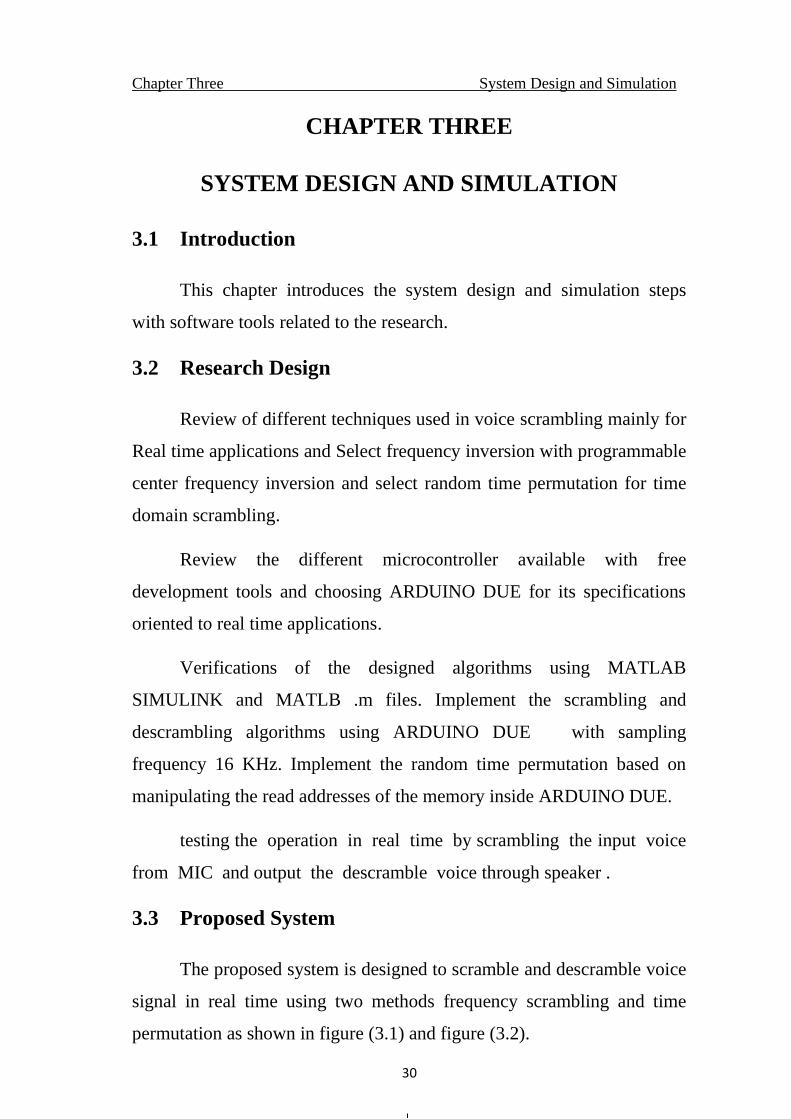
3.3 Proposed System
The proposed system is designed to scramble and descramble voice
signal in real time using two methods frequency scrambling and time
permutation as shown in figure (3.1) and figure (3.2).
Chapter Three System Design and Simulation
31
Figure (3.1) Propose system block diagram for scrambling
Figure (3.2) Propose system block diagram for descrambling
The switches in the above diagrams control the scrambling types
used. For example, if frequency inversion only is used. Swith-2 in
scrambled channel have to pass input-a to DAC.If we want to use
frequency inversion and time scrambling, switch-1 has to pass input-a to
time scrambling module and switch-2 have to pass input-b.
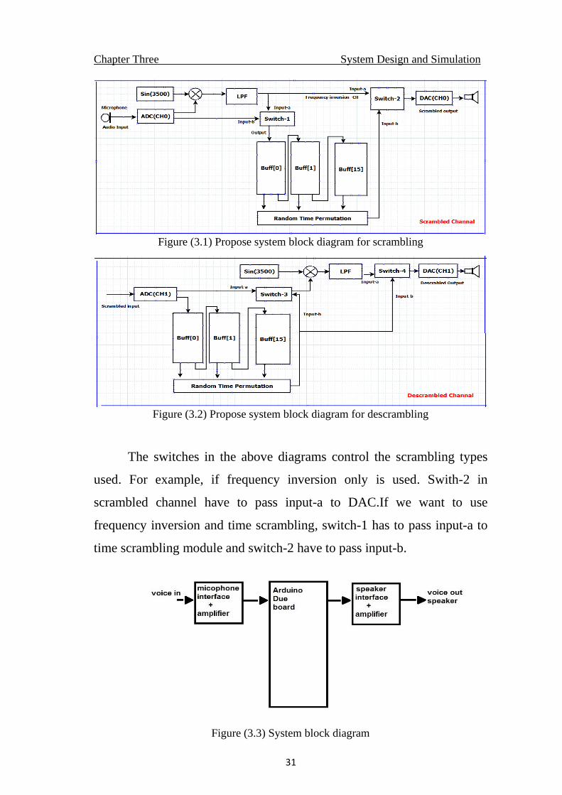
Figure (3.3) System block diagram
Chapter Three System Design and Simulation
32
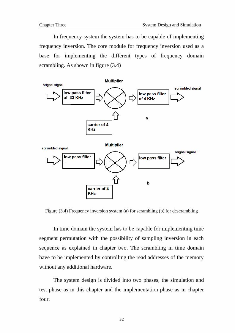
In frequency system the system has to be capable of implementing
frequency inversion. The core module for frequency inversion used as a
base for implementing the different types of frequency domain
scrambling. As shown in figure (3.4)
Figure (3.4) Frequency inversion system (a) for scrambling (b) for descrambling
In time domain the system has to be capable for implementing time
segment permutation with the possibility of sampling inversion in each
sequence as explained in chapter two. The scrambling in time domain
have to be implemented by controlling the read addresses of the memory
without any additional hardware.
The system design is divided into two phases, the simulation and
test phase as in this chapter and the implementation phase as in chapter
four.
Chapter Three System Design and Simulation
33
3.4 Step-1 Matlab Simulink Simulation
MATLAB Simulink is used as step one for verification and
implementation as in the following tests.
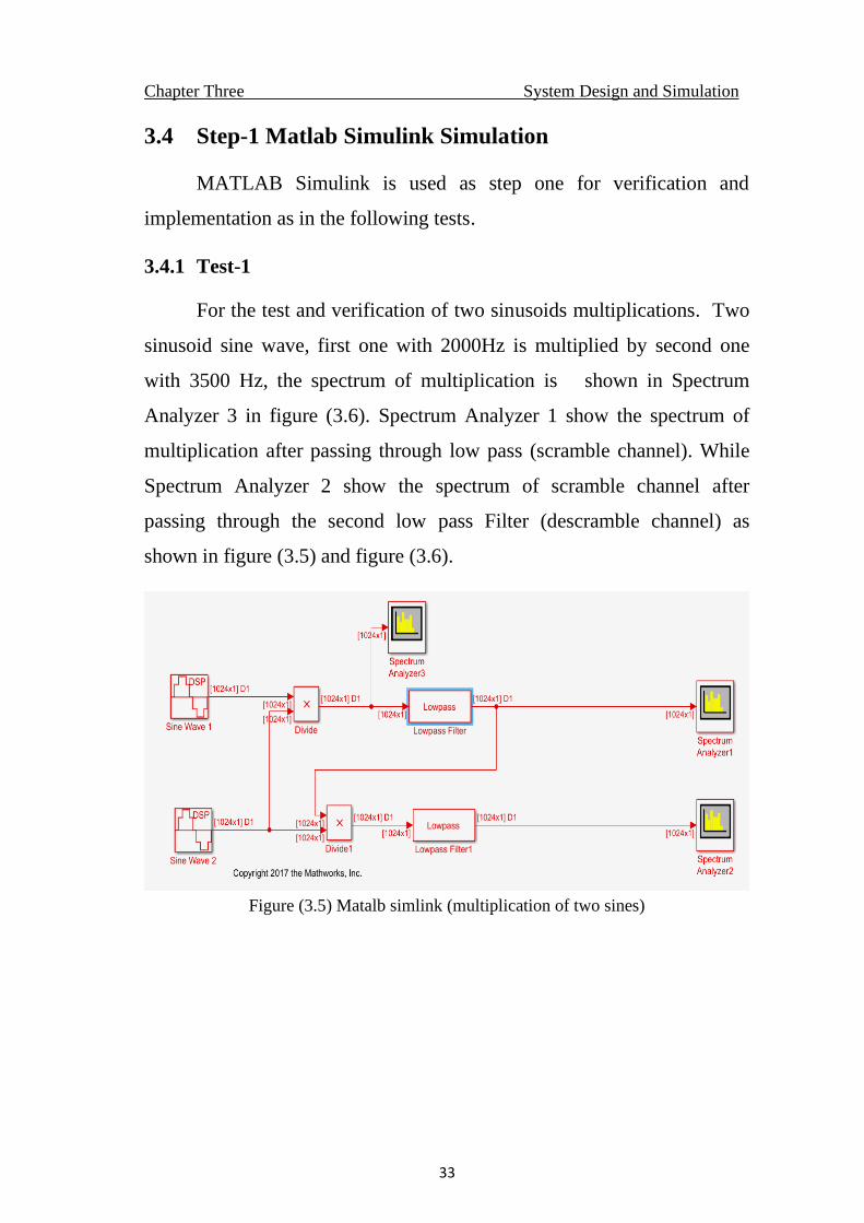
3.4.1 Test-1
For the test and verification of two sinusoids multiplications. Two
sinusoid sine wave, first one with 2000Hz is multiplied by second one
with 3500 Hz, the spectrum of multiplication is shown in Spectrum
Analyzer 3 in figure (3.6). Spectrum Analyzer 1 show the spectrum of
multiplication after passing through low pass (scramble channel). While
Spectrum Analyzer 2 show the spectrum of scramble channel after
passing through the second low pass Filter (descramble channel) as
shown in figure (3.5) and figure (3.6).
Figure (3.5) Matalb simlink (multiplication of two sines)
Chapter Three System Design and Simulation
34
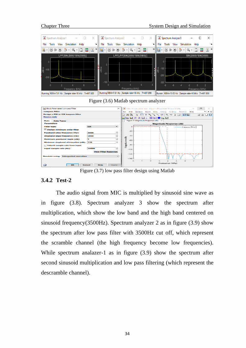
Figure (3.6) Matlab spectrum analyzer
Figure (3.7) low pass filter design using Matlab
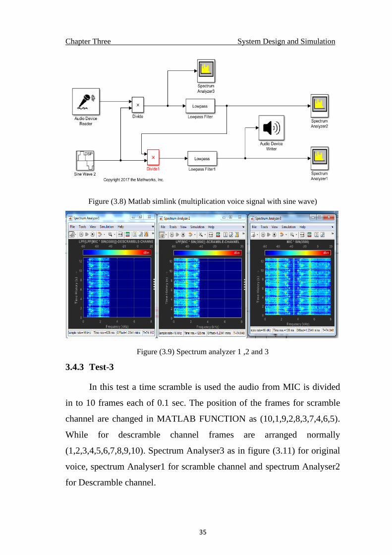
3.4.2 Test-2
The audio signal from MIC is multiplied by sinusoid sine wave as
in figure (3.8). Spectrum analyzer 3 show the spectrum after
multiplication, which show the low band and the high band centered on
sinusoid frequency(3500Hz). Spectrum analyzer 2 as in figure (3.9) show
the spectrum after low pass filter with 3500Hz cut off, which represent
the scramble channel (the high frequency become low frequencies).
While spectrum analazer-1 as in figure (3.9) show the spectrum after
second sinusoid multiplication and low pass filtering (which represent the
descramble channel).
Chapter Three System Design and Simulation
35
Figure (3.8) Matlab simlink (multiplication voice signal with sine wave)
Figure (3.9) Spectrum analyzer 1 ,2 and 3
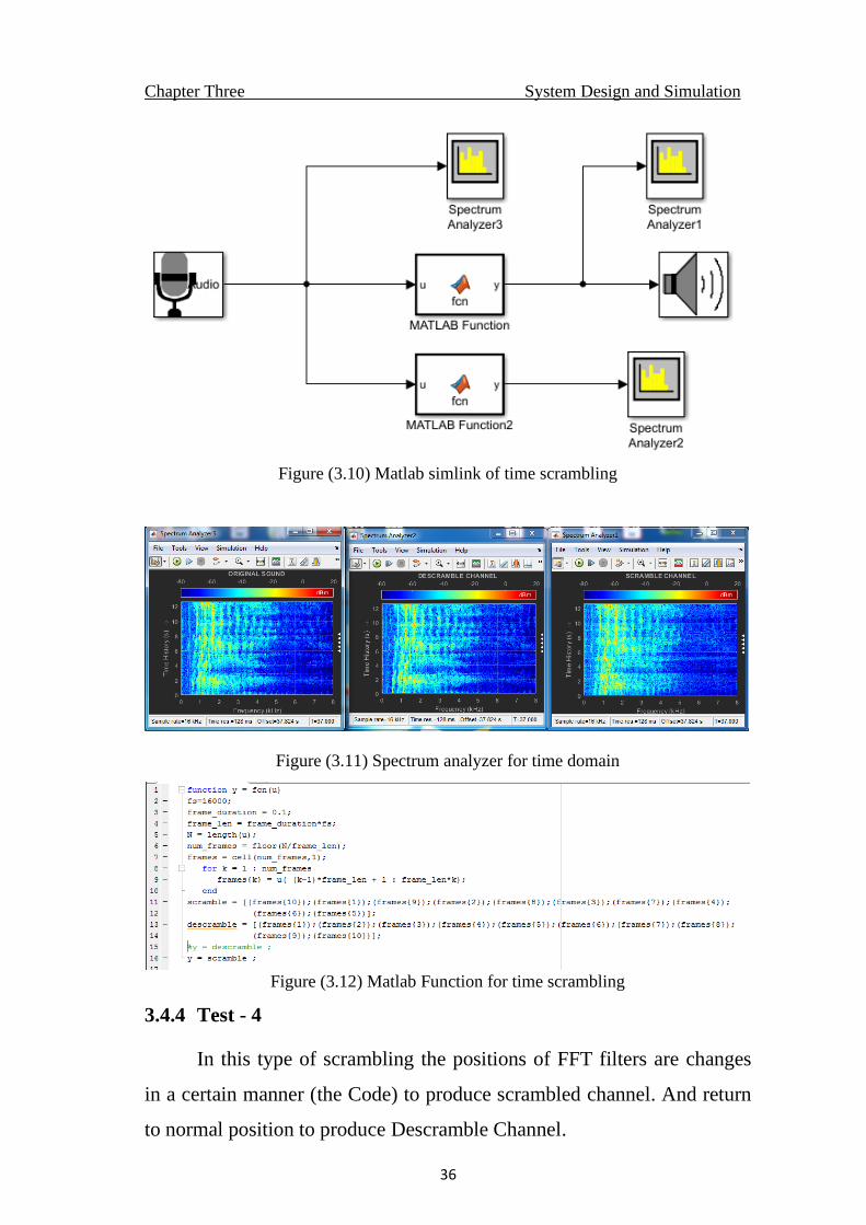
3.4.3 Test-3
In this test a time scramble is used the audio from MIC is divided
in to 10 frames each of 0.1 sec. The position of the frames for scramble
channel are changed in MATLAB FUNCTION as (10,1,9,2,8,3,7,4,6,5).
While for descramble channel frames are arranged normally
(1,2,3,4,5,6,7,8,9,10). Spectrum Analyser3 as in figure (3.11) for original
voice, spectrum Analyser1 for scramble channel and spectrum Analyser2
for Descramble channel.
Chapter Three System Design and Simulation
36
Figure (3.10) Matlab simlink of time scrambling
Figure (3.11) Spectrum analyzer for time domain
Figure (3.12) Matlab Function for time scrambling
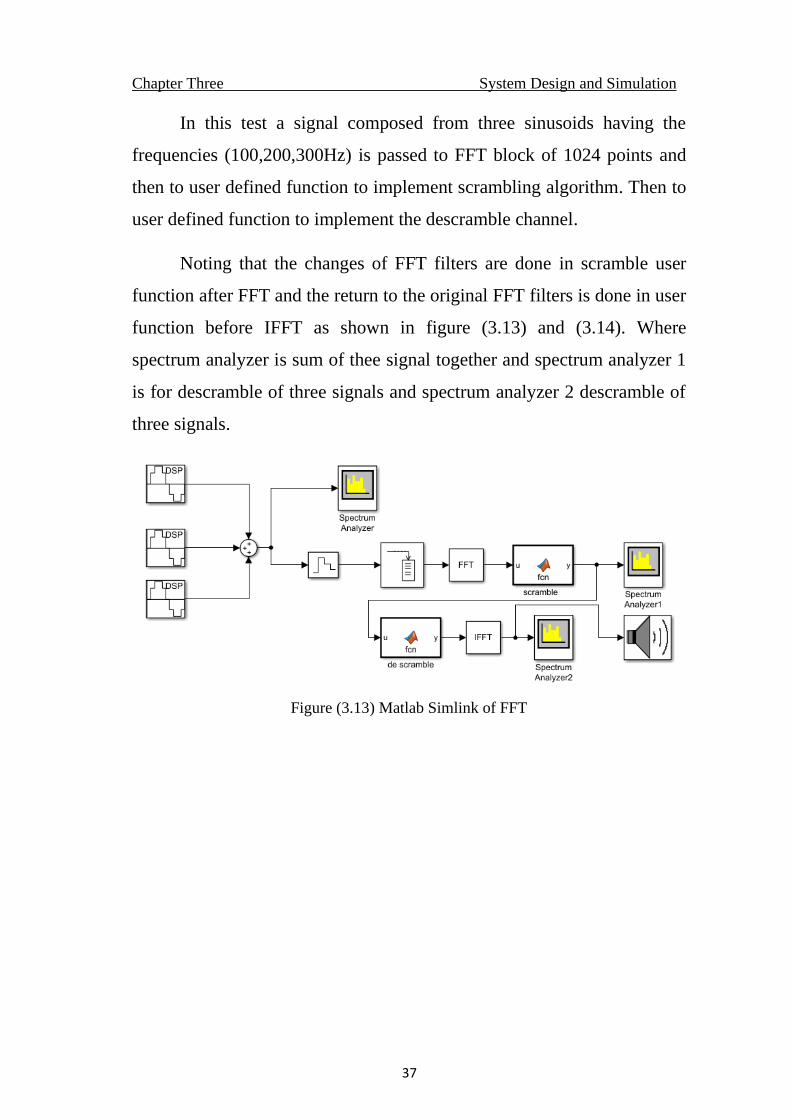
3.4.4 Test - 4
In this type of scrambling the positions of FFT filters are changes
in a certain manner (the Code) to produce scrambled channel. And return
to normal position to produce Descramble Channel.
Chapter Three System Design and Simulation
37
In this test a signal composed from three sinusoids having the
frequencies (100,200,300Hz) is passed to FFT block of 1024 points and
then to user defined function to implement scrambling algorithm. Then to
user defined function to implement the descramble channel.
Noting that the changes of FFT filters are done in scramble user
function after FFT and the return to the original FFT filters is done in user
function before IFFT as shown in figure (3.13) and (3.14). Where
spectrum analyzer is sum of thee signal together and spectrum analyzer 1
is for descramble of three signals and spectrum analyzer 2 descramble of
three signals.
Figure (3.13) Matlab Simlink of FFT
Chapter Three System Design and Simulation
38
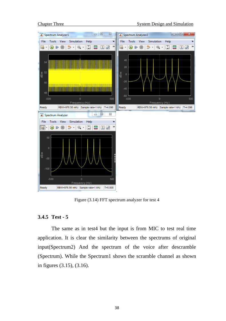
Figure (3.14) FFT spectrum analyzer for test 4
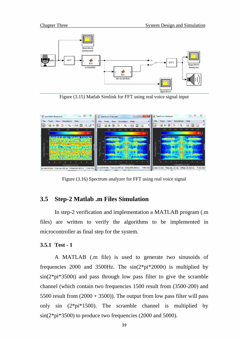
3.4.5 Test - 5
The same as in test4 but the input is from MIC to test real time
application. It is clear the similarity between the spectrums of original
input(Spectrum2) And the spectrum of the voice after descramble
(Spectrum). While the Spectrum1 shows the scramble channel as shown
in figures (3.15), (3.16).
Chapter Three System Design and Simulation
39
Figure (3.15) Matlab Simlink for FFT using real voice signal input
Figure (3.16) Spectrum analyzer for FFT using real voice signal
3.5 Step-2 Matlab .m Files Simulation
In step-2 verification and implementation a MATLAB program (.m
files) are written to verify the algorithms to be implemented in
microcontroller as final step for the system.
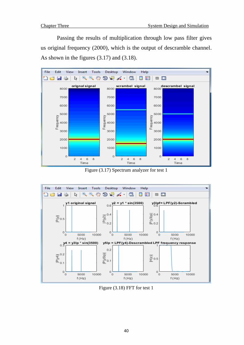
3.5.1 Test - 1
A MATLAB (.m file) is used to generate two sinusoids of
frequencies 2000 and 3500Hz. The sin(2*pi*2000t) is multiplied by
sin(2*pi*3500t) and pass through low pass filter to give the scramble
channel (which contain two frequencies 1500 result from (3500-200) and
5500 result from (2000 + 3500)). The output from low pass filter will pass
only sin (2*pi*1500). The scramble channel is multiplied by
sin(2*pi*3500) to produce two frequencies (2000 and 5000).
Chapter Three System Design and Simulation
40
Passing the results of multiplication through low pass filter gives
us original frequency (2000), which is the output of descramble channel.
As shown in the figures (3.17) and (3.18).
Figure (3.17) Spectrum analyzer for test 1
Figure (3.18) FFT for test 1
Chapter Three System Design and Simulation
41
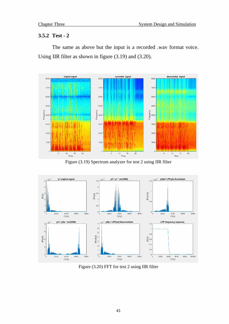
3.5.2 Test - 2
The same as above but the input is a recorded .wav format voice.
Using IIR filter as shown in figure (3.19) and (3.20).
Figure (3.19) Spectrum analyzer for test 2 using IIR filter
Figure (3.20) FFT for test 2 using IIR filter
Chapter Three System Design and Simulation
42
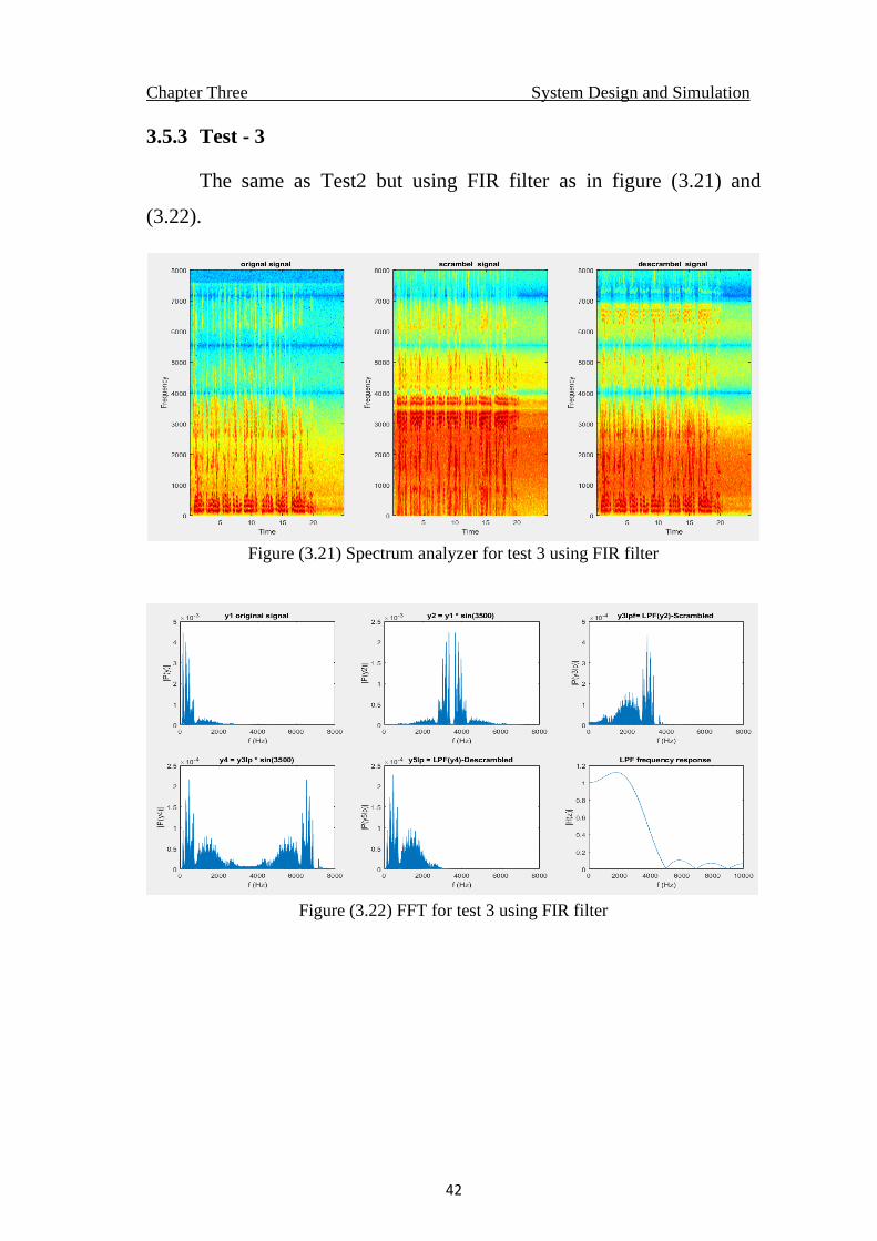
3.5.3 Test - 3
The same as Test2 but using FIR filter as in figure (3.21) and
(3.22).
Figure (3.21) Spectrum analyzer for test 3 using FIR filter
Figure (3.22) FFT for test 3 using FIR filter
Chapter Three System Design and Simulation
43
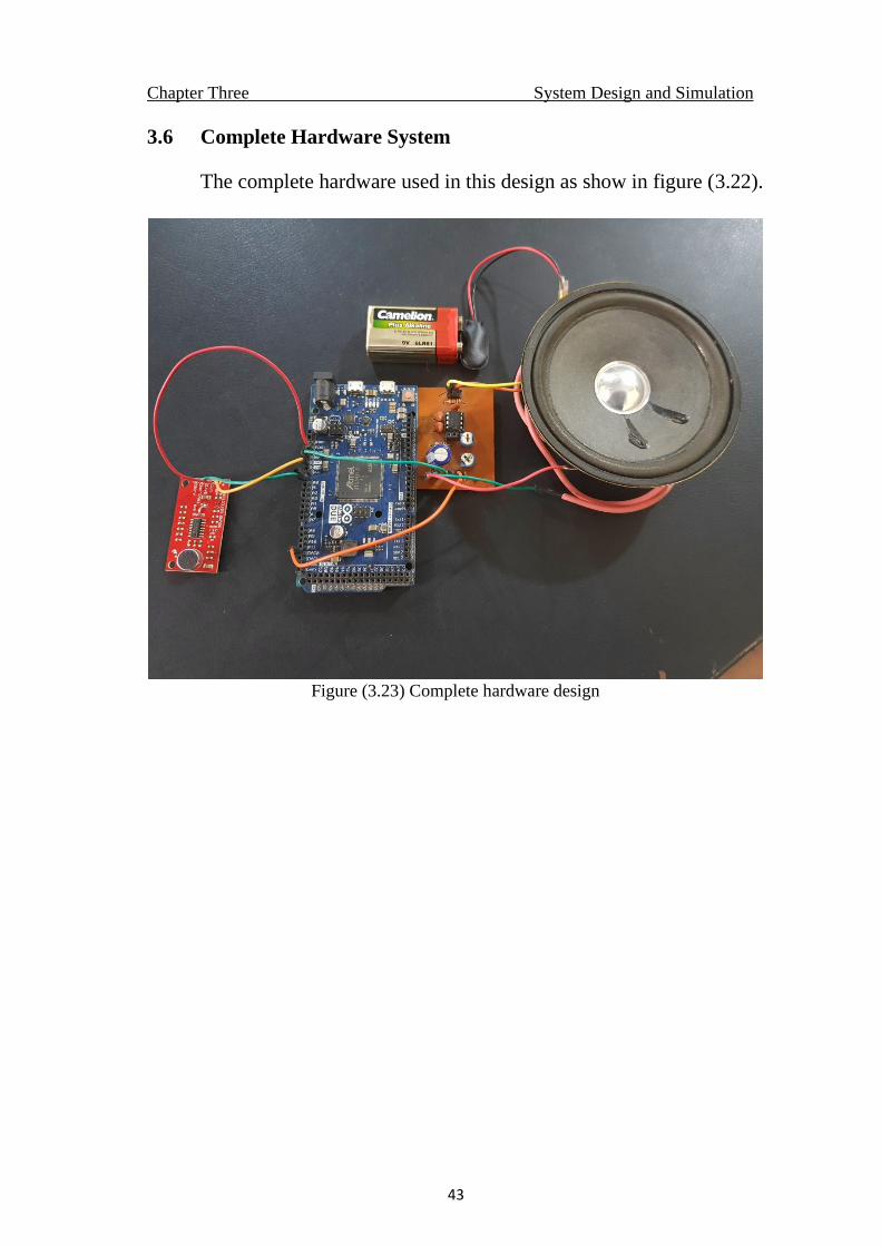
3.6 Complete Hardware System
The complete hardware used in this design as show in figure (3.22).
Figure (3.23) Complete hardware design
CHAPTER FOUR
SYSTEM IMPLEMENTATION
Chapter Four System Implementation
44
CHAPTER FOUR
SYSTEM IMPLEMENTATION
4.1 Introduction
This chapter introduces the system implementation in
microcontroller and tests done to verify system functionality and
eligibility
4.2 Design Implementation
4.2.1 Frequency Scrambling Implementation
4.2.1.1 Sampling Frequency Generation
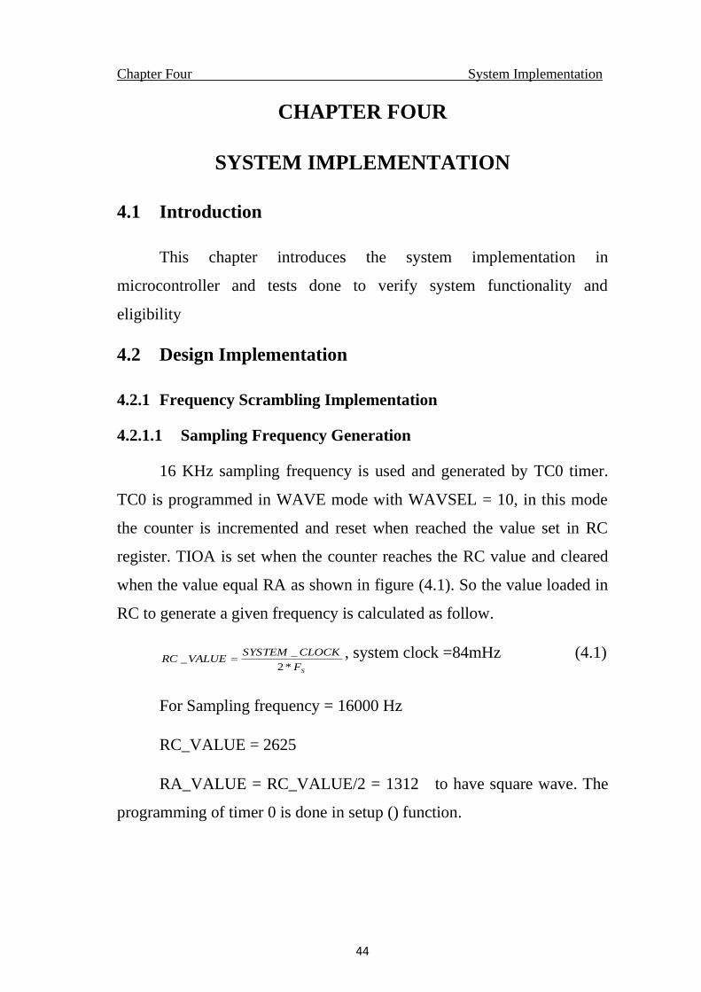
16 KHz sampling frequency is used and generated by TC0 timer.
TC0 is programmed in WAVE mode with WAVSEL = 10, in this mode
the counter is incremented and reset when reached the value set in RC
register. TIOA is set when the counter reaches the RC value and cleared
when the value equal RA as shown in figure (4.1). So the value loaded in
RC to generate a given frequency is calculated as follow.
SF
CLOCKSYSTEMVALUERC
*2
__ = , system clock =84mHz (4.1)
For Sampling frequency = 16000 Hz
RC_VALUE = 2625
RA_VALUE = RC_VALUE/2 = 1312 to have square wave. The
programming of timer 0 is done in setup () function.
Chapter Four System Implementation
45
Figure (4.1) Sampling frequency generation
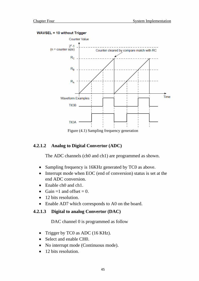
4.2.1.2 Analog to Digital Convertor (ADC)
The ADC channels (ch0 and ch1) are programmed as shown.
• Sampling frequency is 16KHz generated by TC0 as above.
• Interrupt mode when EOC (end of conversion) status is set at the
end ADC conversion.
• Enable ch0 and ch1.
• Gain =1 and offset = 0.
• 12 bits resolution.
• Enable AD7 which corresponds to A0 on the board.
4.2.1.3 Digital to analog Convertor (DAC)
DAC channel 0 is programmed as follow
• Trigger by TC0 as ADC (16 KHz).
• Select and enable CH0.
• No interrupt mode (Continuous mode).
• 12 bits resolution.
Chapter Four System Implementation
46
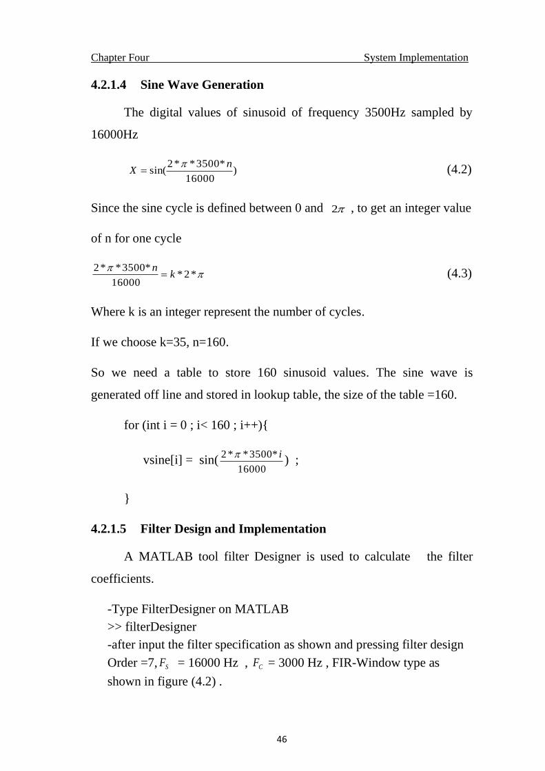
4.2.1.4 Sine Wave Generation
The digital values of sinusoid of frequency 3500Hz sampled by
16000Hz
)16000
*3500**2sin(
nX
=
(4.2)
Since the sine cycle is defined between 0 and 2 , to get an integer value
of n for one cycle
*2*16000
*3500**2k
n= (4.3)
Where k is an integer represent the number of cycles.
If we choose k=35, n=160.
So we need a table to store 160 sinusoid values. The sine wave is
generated off line and stored in lookup table, the size of the table =160.
for (int i = 0 ; i< 160 ; i++){
vsine[i] = sin(16000
*3500**2 i) ;
}
4.2.1.5 Filter Design and Implementation
A MATLAB tool filter Designer is used to calculate the filter
coefficients.
-Type FilterDesigner on MATLAB
>> filterDesigner
-after input the filter specification as shown and pressing filter design
Order =7, SF = 16000 Hz , CF = 3000 Hz , FIR-Window type as
shown in figure (4.2) .
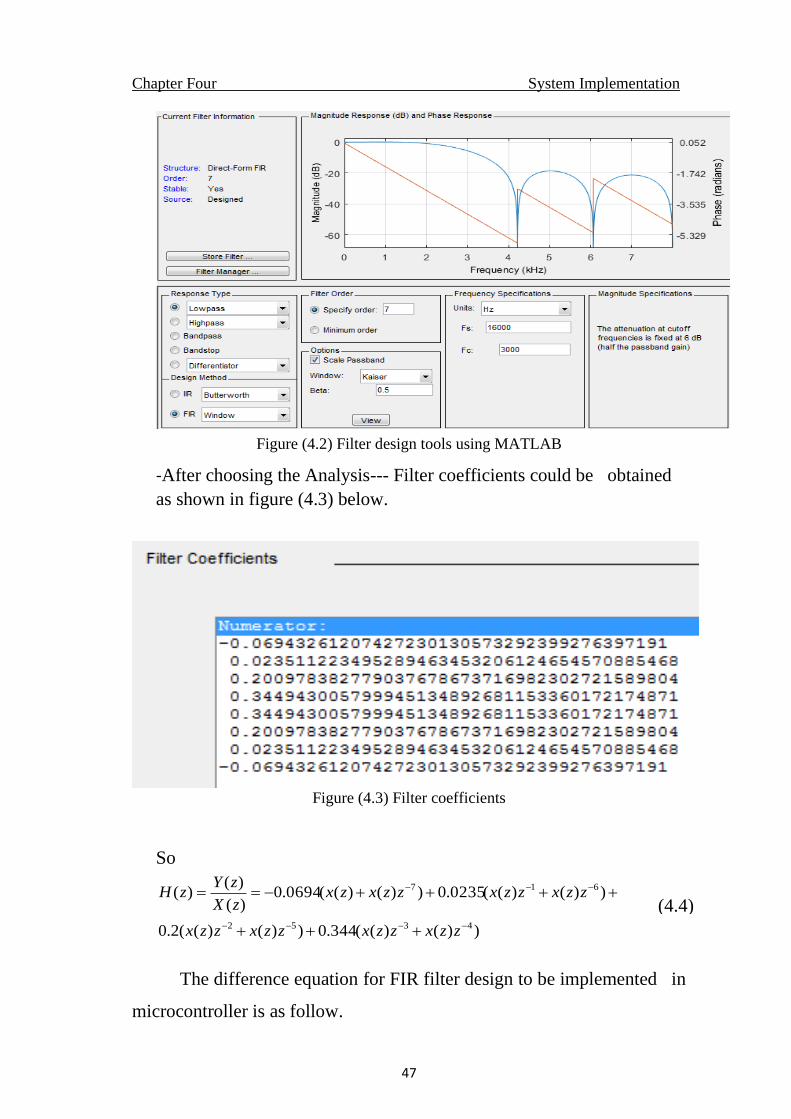
Chapter Four System Implementation
47
Figure (4.2) Filter design tools using MATLAB
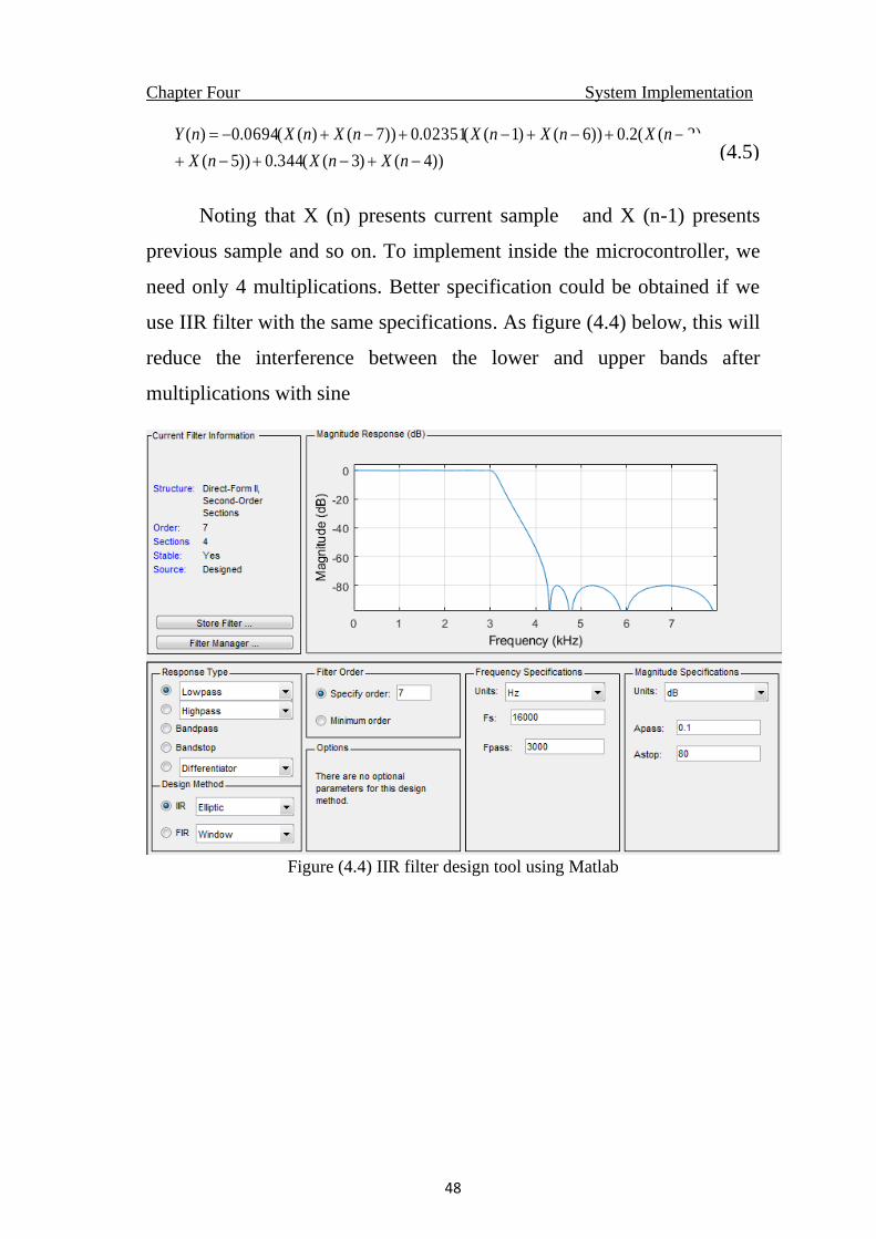
-After choosing the Analysis--- Filter coefficients could be obtained
as shown in figure (4.3) below.
Figure (4.3) Filter coefficients
So
))()((344.0))()((2.0
))()((0235.0))()((0694.0)(
)()(
4352
617
−−−−
−−−
+++
++++−==
zzxzzxzzxzzx
zzxzzxzzxzxzX
zYzH
The difference equation for FIR filter design to be implemented in
microcontroller is as follow.
(4.4)
Chapter Four System Implementation
48
))4()3((344.0))5(
)2((2.0))6()1((02351.0))7()((0694.0)(
−+−+−+
−+−+−+−+−=
nXnXnX
nXnXnXnXnXnY
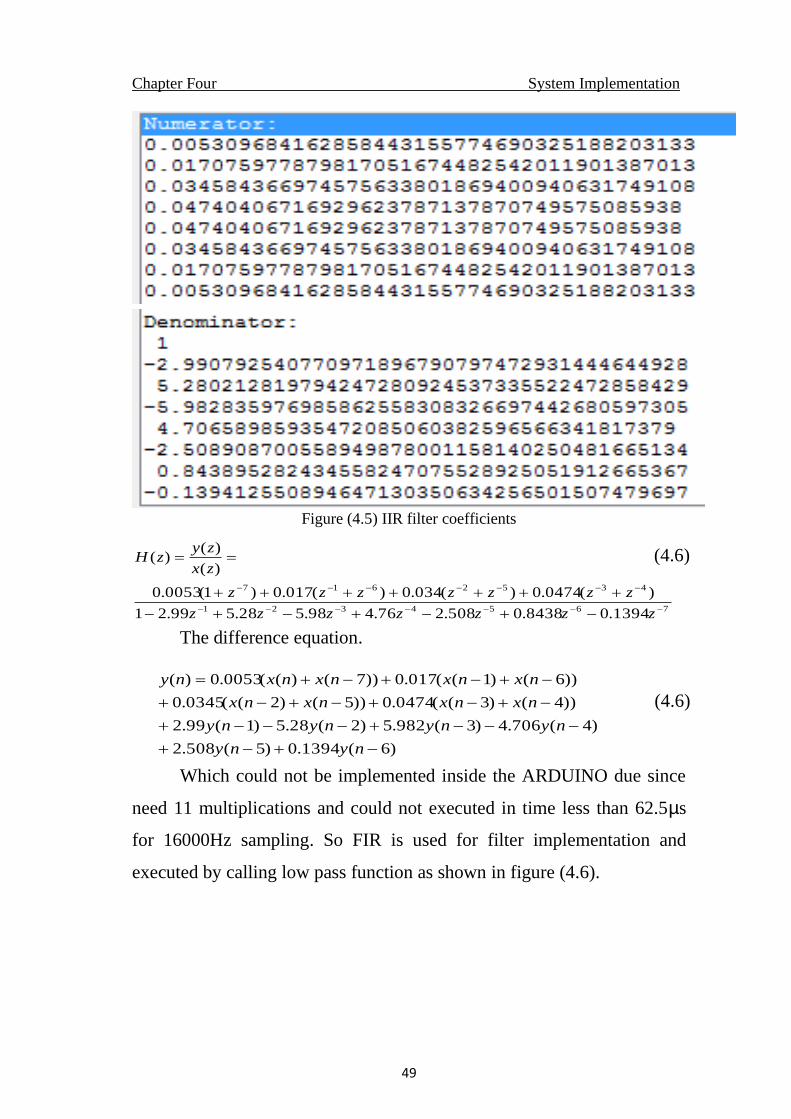
Noting that X (n) presents current sample and X (n-1) presents
previous sample and so on. To implement inside the microcontroller, we
need only 4 multiplications. Better specification could be obtained if we
use IIR filter with the same specifications. As figure (4.4) below, this will
reduce the interference between the lower and upper bands after
multiplications with sine
Figure (4.4) IIR filter design tool using Matlab
(4.5)
Chapter Four System Implementation
49
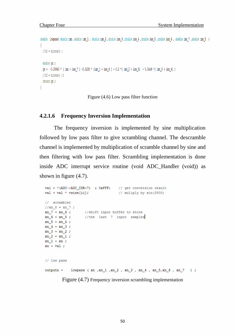
Figure (4.5) IIR filter coefficients
7654321
4352617
1394.08438.0508.276.498.528.599.21
)(0474.0)(034.0)(017.0)1(0053.0
)(
)()(
−−−−−−−
−−−−−−−
−+−+−+−
+++++++
==
zzzzzzz
zzzzzzz
zx
zyzH
The difference equation.
)6(1394.0)5(508.2
)4(706.4)3(982.5)2(28.5)1(99.2
))4()3((0474.0))5()2((0345.0
))6()1((017.0))7()((0053.0)(
−+−+
−−−+−−−+
−+−+−+−+
−+−+−+=
nyny
nynynyny
nxnxnxnx
nxnxnxnxny
Which could not be implemented inside the ARDUINO due since
need 11 multiplications and could not executed in time less than 62.5µs
for 16000Hz sampling. So FIR is used for filter implementation and
executed by calling low pass function as shown in figure (4.6).
(4.6)
(4.6)
Chapter Four System Implementation
50
Figure (4.6) Low pass filter function
4.2.1.6 Frequency Inversion Implementation
The frequency inversion is implemented by sine multiplication
followed by low pass filter to give scrambling channel. The descramble
channel is implemented by multiplication of scramble channel by sine and
then filtering with low pass filter. Scrambling implementation is done
inside ADC interrupt service routine (void ADC_Handler (void)) as
shown in figure (4.7).
Figure (4.7) Frequency inversion scrambling implementation
Chapter Four System Implementation
51
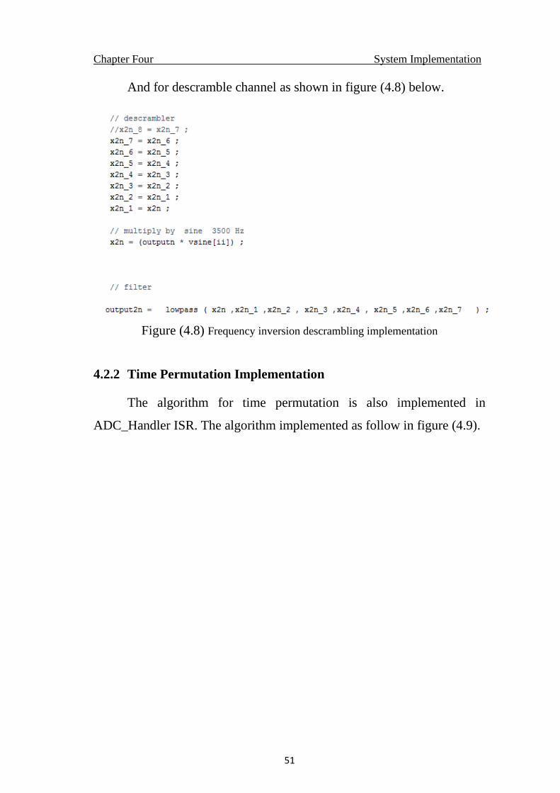
And for descramble channel as shown in figure (4.8) below.
Figure (4.8) Frequency inversion descrambling implementation
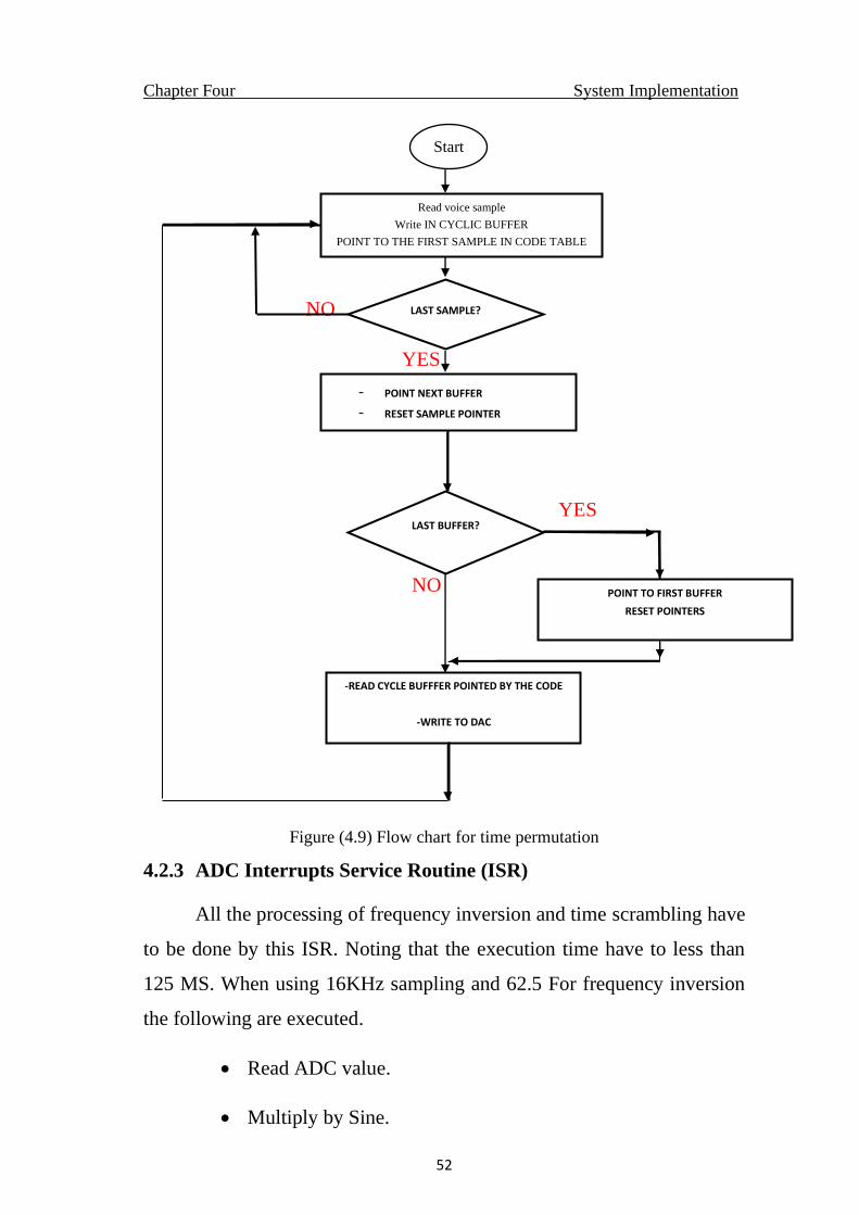
4.2.2 Time Permutation Implementation
The algorithm for time permutation is also implemented in
ADC_Handler ISR. The algorithm implemented as follow in figure (4.9).
Chapter Four System Implementation
52
NO
YES
YES
NO
Figure (4.9) Flow chart for time permutation
4.2.3 ADC Interrupts Service Routine (ISR)
All the processing of frequency inversion and time scrambling have
to be done by this ISR. Noting that the execution time have to less than
125 MS. When using 16KHz sampling and 62.5 For frequency inversion
the following are executed.
• Read ADC value.
• Multiply by Sine.
LAST SAMPLE?
Read voice sample
Write IN CYCLIC BUFFER
POINT TO THE FIRST SAMPLE IN CODE TABLE
- POINT NEXT BUFFER
- RESET SAMPLE POINTER
-
LAST BUFFER?
POINT TO FIRST BUFFER
RESET POINTERS
-READ CYCLE BUFFFER POINTED BY THE CODE
-WRITE TO DAC
Start
Chapter Four System Implementation
53
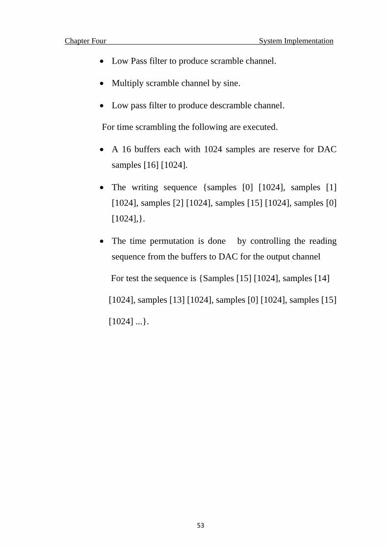
• Low Pass filter to produce scramble channel.
• Multiply scramble channel by sine.
• Low pass filter to produce descramble channel.
For time scrambling the following are executed.
• A 16 buffers each with 1024 samples are reserve for DAC
samples [16] [1024].
• The writing sequence {samples [0] [1024], samples [1]
[1024], samples [2] [1024], samples [15] [1024], samples [0]
[1024],}.
• The time permutation is done by controlling the reading
sequence from the buffers to DAC for the output channel
For test the sequence is {Samples [15] [1024], samples [14]
[1024], samples [13] [1024], samples [0] [1024], samples [15]
[1024] ...}.
CHAPTER FIVE
RESULTS AND DISCUSSIONS
Chapter Five Results and Discussions
54
CHAPTER FIVE
RESULTS AND DISCUSSIONS
5.1 Introduction
This chapter introduces the system validation tests and results using
arduino microcontroller program.
5.2 Static Tests
An ARDUINO software is written to read the voice from the MIC
with 16KHz using 7-order FIR filter with cut off frequency of 3000Hz,
the sine wave used is 3500Hz.
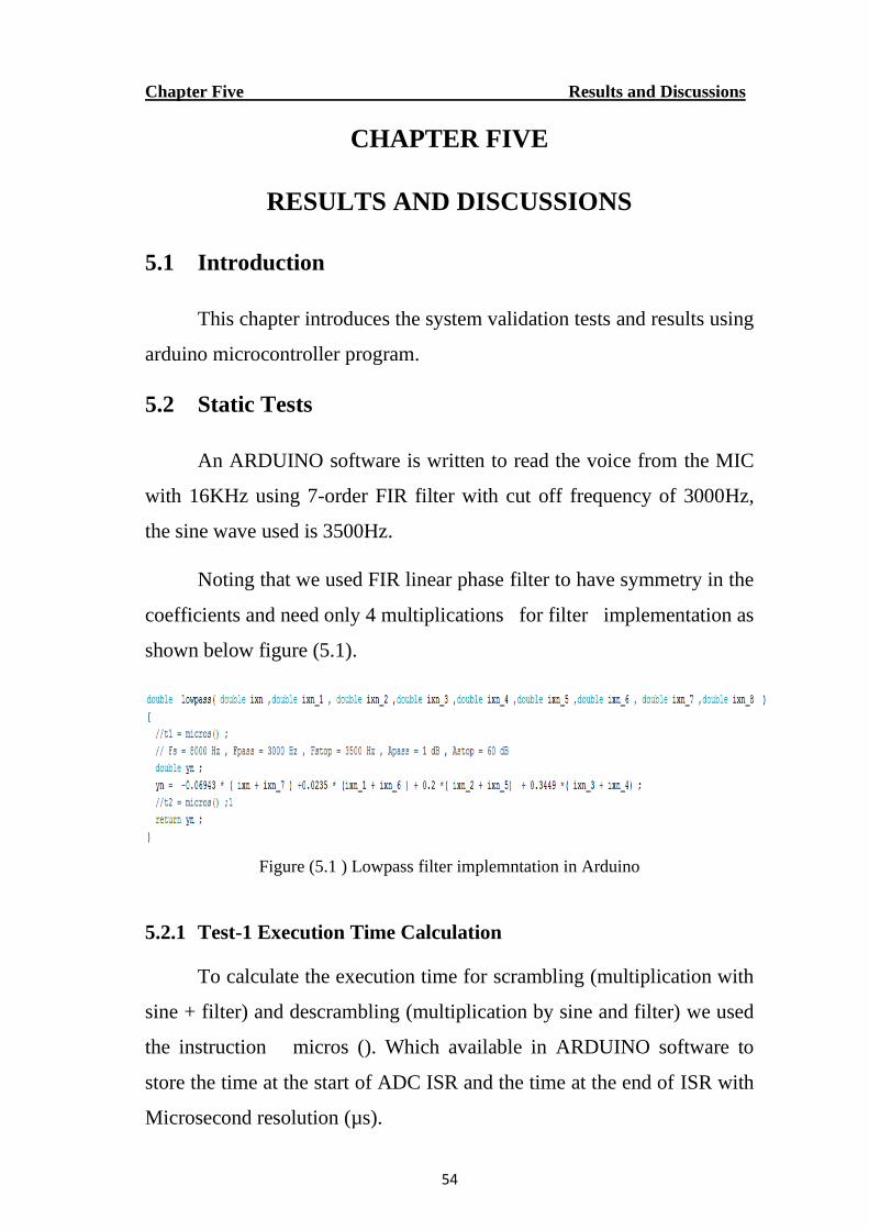
Noting that we used FIR linear phase filter to have symmetry in the
coefficients and need only 4 multiplications for filter implementation as
shown below figure (5.1).
Figure (5.1 ) Lowpass filter implemntation in Arduino
5.2.1 Test-1 Execution Time Calculation
To calculate the execution time for scrambling (multiplication with
sine + filter) and descrambling (multiplication by sine and filter) we used
the instruction micros (). Which available in ARDUINO software to
store the time at the start of ADC ISR and the time at the end of ISR with
Microsecond resolution (µs).
Chapter Five Results and Discussions
55
t1 = micros ();
t2 = micros ();
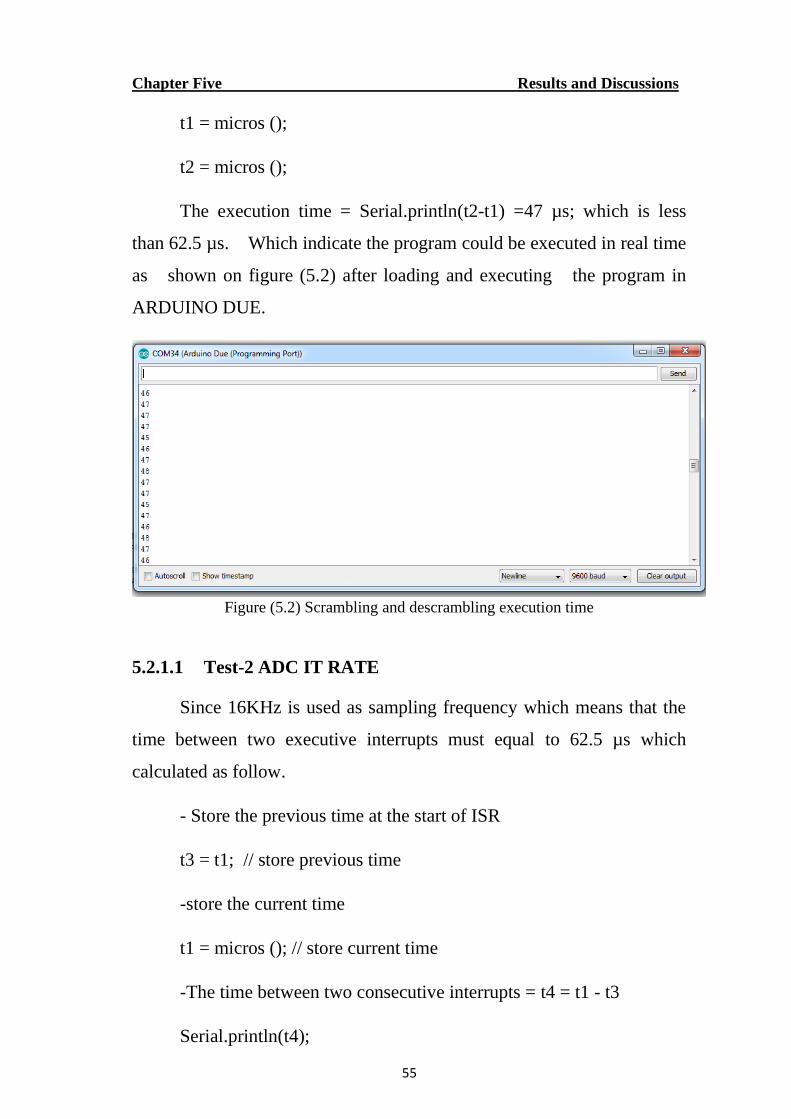
The execution time = Serial.println(t2-t1) =47 µs; which is less
than 62.5 µs. Which indicate the program could be executed in real time
as shown on figure (5.2) after loading and executing the program in
ARDUINO DUE.
Figure (5.2) Scrambling and descrambling execution time
5.2.1.1 Test-2 ADC IT RATE
Since 16KHz is used as sampling frequency which means that the
time between two executive interrupts must equal to 62.5 µs which
calculated as follow.
- Store the previous time at the start of ISR
t3 = t1; // store previous time
-store the current time
t1 = micros (); // store current time
-The time between two consecutive interrupts = t4 = t1 - t3
Serial.println(t4);
Chapter Five Results and Discussions
56
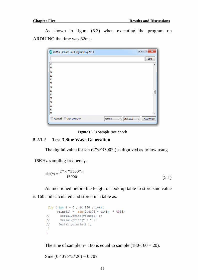
As shown in figure (5.3) when executing the program on
ARDUINO the time was 62ms.
Figure (5.3) Sample rate check
5.2.1.2 Test 3 Sine Wave Generation
The digital value for sin (2*π*3500*t) is digitized as follow using
16KHz sampling frequency.
16000
*3500**2)sin(
nn
=
(5.1)
As mentioned before the length of look up table to store sine value
is 160 and calculated and stored in a table as.
The sine of sample n= 180 is equal to sample (180-160 = 20).
Sine (0.4375*π*20) = 0.707
Chapter Five Results and Discussions
57
Sine (0.4375* π*180) = 0.707
5.2.1.3 Time Scrambling Implementation Test
The input is stored in circular buffer (0---15) defined in the
program as two-dimension variable. (volatile int samples [16] [BUFSIZE]
;) where BUFSIZE = 1024). The read from the circular buffer is done as
define in the code defined in the program as.
volatile int code [16] = {15,14,13,12,11,10,9,8,7,6,5,4,3,2,1,0};
The scrambled time output written to DAC is defined as
dac_write (samples [obufn] [sptr]);
Where obufn = code[k] , k = 0------15
Test-1
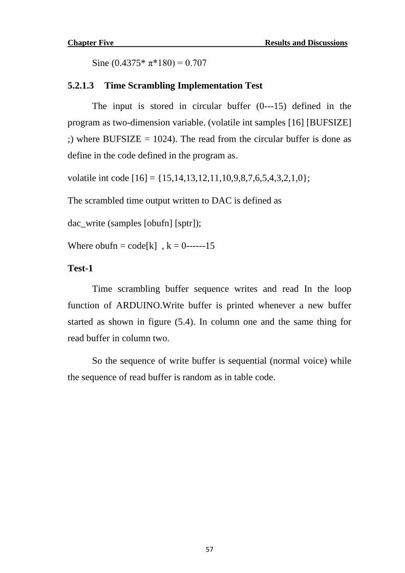
Time scrambling buffer sequence writes and read In the loop
function of ARDUINO.Write buffer is printed whenever a new buffer
started as shown in figure (5.4). In column one and the same thing for
read buffer in column two.
So the sequence of write buffer is sequential (normal voice) while
the sequence of read buffer is random as in table code.
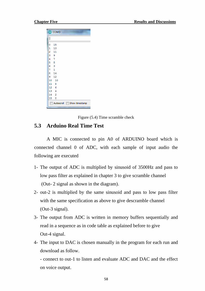
Chapter Five Results and Discussions
58
Figure (5.4) Time scramble check
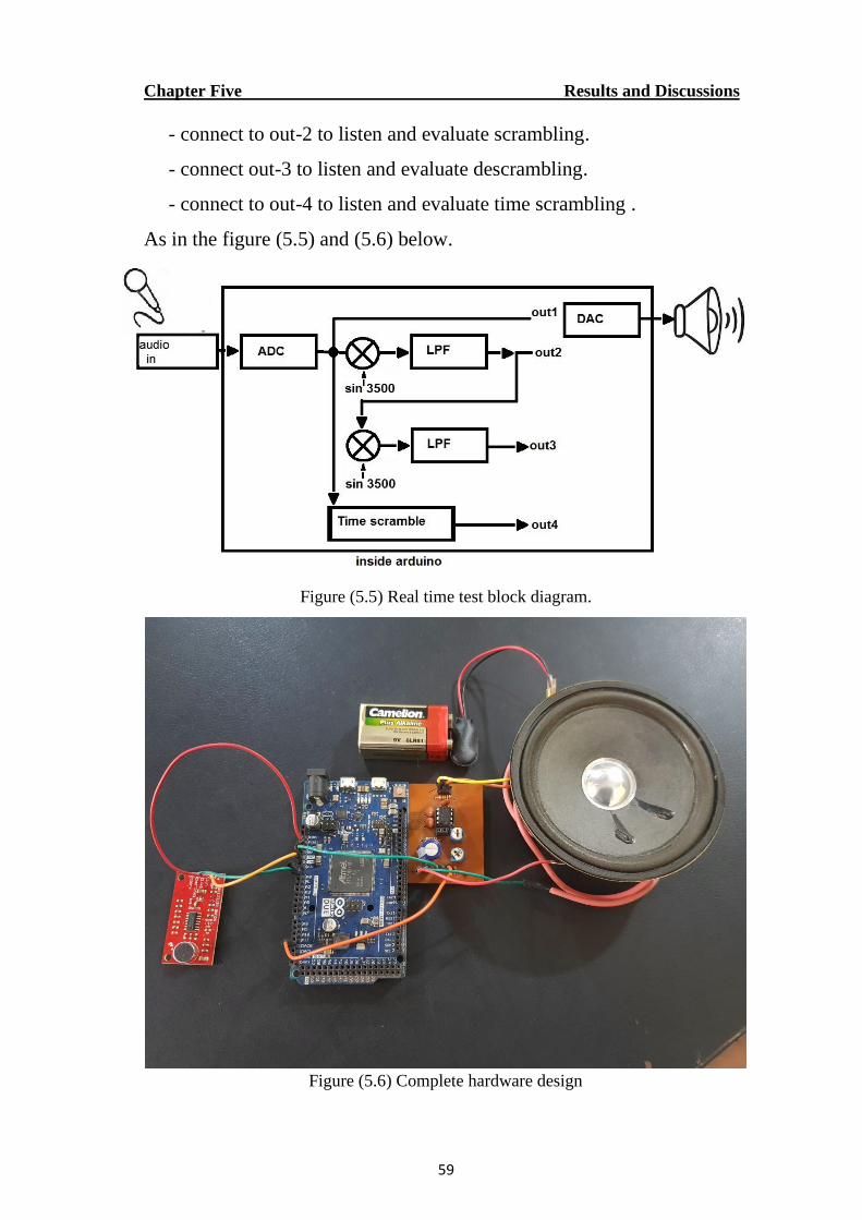
5.3 Arduino Real Time Test
A MIC is connected to pin A0 of ARDUINO board which is
connected channel 0 of ADC, with each sample of input audio the
following are executed
1- The output of ADC is multiplied by sinusoid of 3500Hz and pass to
low pass filter as explained in chapter 3 to give scramble channel
(Out- 2 signal as shown in the diagram).
2- out-2 is multiplied by the same sinusoid and pass to low pass filter
with the same specification as above to give descramble channel
(Out-3 signal).
3- The output from ADC is written in memory buffers sequentially and
read in a sequence as in code table as explained before to give
Out-4 signal.
4- The input to DAC is chosen manually in the program for each run and
download as follow.
- connect to out-1 to listen and evaluate ADC and DAC and the effect
on voice output.
Chapter Five Results and Discussions
59
- connect to out-2 to listen and evaluate scrambling.
- connect out-3 to listen and evaluate descrambling.
- connect to out-4 to listen and evaluate time scrambling .
As in the figure (5.5) and (5.6) below.
Figure (5.5) Real time test block diagram.
Figure (5.6) Complete hardware design
CHAPTER SIX
CONCLUSION AND FUTURE WORK
Chapter Six Conclusion and Future Work
60
CHAPTER SIX
CONCLUSION AND FUTURE WORK
6.1 Conclusion
The real time implementation of frequency inversion could be
achieved using advanced microcontroller with specifications oriented to
real time application like ADC, DAC working with DMA and interrupt
mode with low latency time.
The different advanced techniques based on frequency inversion
like Rolling Code Scrambling, Frequency Hopping and frequency
sweeping could be achieved by changing the frequency center through
software which gives high Flexibility in changing the code.
The time permutation scrambling was achieved through address
manipulation of memory buffers for read and write, the data from ADC
are write in circular buffers while the read from buffers is done randomly
as stored in code table without additional burden on microcontroller.
System implementation based on MATLAB (Simulink and .m
files) show some delay between the voice input and the output using the
PC. Although using more advanced PC with multi-processors techniques
could reduce the delay but it still not suitable for portable real time
operation. Using IIR filter in frequency inversion will give better result
but need more multiplications than FIR filters and more execution time,
so FIR is used for microcontroller implementation.
The effectiveness of scrambling is determined by the amount of
residual intelligibility which indicates the amount of redundant
information which helps in easier recovery of the original signal.
Chapter Six Conclusion and Future Work
61
The parameters used to measure the residual intelligibility need
more processing which could not be implemented in real time using the
proposed hardware. The intelligibility is evaluated by using trained and
untrained human listeners to listen to the scramble audio.
6.2 Future Work
A more accurate and higher sampling frequency with higher filter
order could be achieved using microcontroller or DSP with floating point
operation.
More emphasis has to be done on synchronization between
scrambler and descrambler specially for time domain scrambling. More
research and analysis for the design and implementation of voice
scrambling without the need for synchronization specially the
implementation of multi-band pass filters based on the processing of
voice
The residual intelligibility has to be measured for different
algorithms used in this work. Which could be done by logging the
scrambled audio on SD card in real time and later transfer to PC for
calculation and evaluation, or transferring the scrambled audio to PC
through high speed link between the ARDUINO Due board and the PC.
The system could be implemented using System on Chip
technology (SOC). Which contain processor and logic on the same chip.
For example, Xilinx Zynq 7000 family which contain two processors
working in parallel with 1 GHz and 1.5 million gates for more
professional system.
REFRENCES
62
REFRENCES
[Al-Sabbagh [1], Hayati, et al. [2], G and J [3], Bagwe, et al. [4], Enache, et al. [5], Sa mir J. Mohammad [6], Anjana D S [7], A l-Saadi [8], Hemlata Kohad [9], Francisco Ass is de O. Nascimento [10], Ikram [11], Frederick Huang [12], Huang and Stansfield [13], Malvar [14], Matsunaga, et al. [15], Udalov [16]]
[1] T. Al-Sabbagh, "Front End to Back End Speech Scrambler,"
International Journal of Computing and Network Technology, vol.
7, pp. 65-70, 01/08 2020.
[2] N. Hayati, Y. Suryanto, K. Ramli, and M. Suryanegara, End-to-End
Voice Encryption Based on Multiple Circular Chaotic Permutation,
2019.
[3] D. G and J. J, "An efficient voice scrambling technique for next
generation communication systems," International Journal of
Engineering and Technology, vol. 8, 02/01 2016.
[4] G. Bagwe, D. Apsingekar, S. Gandhare, and S. Pawar, Voice
encryption and decryption in telecommunication, 2016.
[5] F. Enache, D. Deparateanu, T. Oroian, F. Popescu, and I. Vizitiu,
"Theoretical and practical implementation of scrambling algorithms
for speech signals," in 2015 7th International Conference on
Electronics, Computers and Artificial Intelligence (ECAI), 2015,
pp. S-49-S-52.
[6] L. A. A.-R. Samir J. Mohammad, "Modified Scrambling Based on
permutation function Matrix and 2D-DMWT with QPSK," 2014.
[7] M. K. Anjana D S, "Frequency Speech Scrambler based on Hartley
Transform and OFDM Algorithm," 2013.
[8] L. H. M. Al-Saadi, "Analog Speech Encryption Based On
Biorthogonal Transforms," 2013.
[9] P. V. R. I. Hemlata Kohad, Dr.M.A.Gaikwad, "An Overview of
Speech Encryption Techniques," 2012.
[10] R. G. T. Francisco Assis de O. Nascimento, "Frequency Speech
Scrambler Based on the Hartley Transform and the Insertion of
Random Frequency Components," 2012.
[11] J. A. a. N. Ikram, "Frequency-domain speech
scrambling/descrambling techniques implementation and
evaluation on DSP," 7th International Multi Topic Conference,
2003. INMIC 2003., Islamabad, Pakistan, 2003, pp. 44-48, doi:
10.1109/INMIC.2003.1416613., 2003 2003.
[12] Frederick Huang, "United States Patent, Patent Number:
4,773,092," 1998.
63
[13] F. Huang and E. V. Stansfield, "Time sample speech scrambler
which does not require synchronization," IEEE Transactions on
Communications, vol. 41, pp. 1715-1722, 1993.
[14] H. S. Malvar, "A TMS320C25-based telephone scrambler using
fast-computable filter banks," 1992.
[15] A. Matsunaga, M. Ohkawa, K. Koga, and K. Sakurai, "A full-
duplex analog speech scrambler using the FFT technique and its
performance," Electronics and Communications in Japan (Part III:
Fundamental Electronic Science), vol. 73, pp. 85-97, 1990.
[16] S. Udalov, "MICROPROCESSOR-BASED ANALOG VOICE
SCRAMBLING TECHNIQUES," 1979.

APPENDICES
64
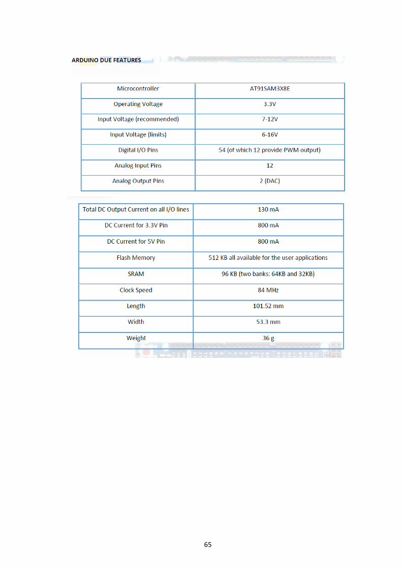
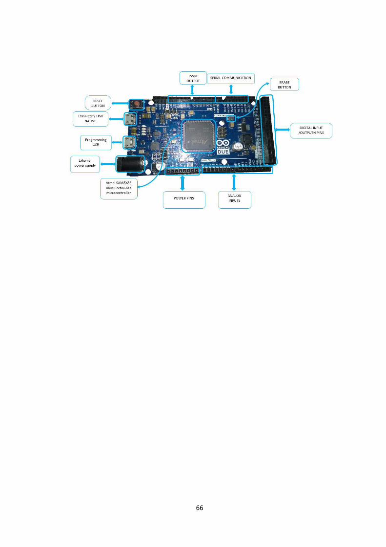
Appendix A
Arduino Due
65
66
67
Appendix B
Lm386 Low Voltage Audio Power Amplifier
68
69
Appendix C
Arduino system code
// Serial.println(sptr);
#define BUFSIZE 0x400
#define BUFMASK 0x3FF
volatile int samples[16] [BUFSIZE] ;
volatile int code[16] = { 15,14,13,12,11,10,9,8,7,6,5,4,3,2,1,0 } ; // change manuplation
//double vReal1[BUFSIZE] ;
volatile int sptr = 0 ,bufn = 0 , obufn = 2 , obufn2 = 1;
volatile int isr_count = 0 ; // this was for debugging
unsigned long t1 , t2 , t3 , t4 , t5 , t6 ;
int fs = 2625 , id_buf_full=0 , id_buf_full2 = 0 , ii = 0; // sampling freq = 16000Hz
int k = 0 ; // code index
double xn ,xn_1 , xn_2,xn_3 , xn_4, xn_5, xn_6 , xn_7, xn_8 ;
double x2n ,x2n_1 , x2n_2 ,x2n_3 , x2n_4, x2n_5 ,x2n_6 , x2n_7 ,x2n_8;
double outputn ;
double output2n ;
int x= 1 , amp = 4095 ;
double vsine[160], pi = 3.141592654 ;
int val,val2 ;
void setup()
{
Serial.begin (9600) ;
adc_setup () ;
pmc_enable_periph_clk (TC_INTERFACE_ID + 0*3+0) ;
TcChannel * t = &(TC0->TC_CHANNEL)[0] ;
t->TC_CCR = TC_CCR_CLKDIS ;
t->TC_IDR = 0xFFFFFFFF ;
t->TC_SR ;
t->TC_CMR = TC_CMR_TCCLKS_TIMER_CLOCK1 |
TC_CMR_WAVE |
TC_CMR_WAVSEL_UP_RC |
TC_CMR_EEVT_XC0 |
TC_CMR_ACPA_CLEAR | TC_CMR_ACPC_CLEAR |
TC_CMR_BCPB_CLEAR | TC_CMR_BCPC_CLEAR ;
t->TC_RC = fs ;
t->TC_RA = fs/2 ;
t->TC_CMR = (t->TC_CMR & 0xFFF0FFFF) | TC_CMR_ACPA_CLEAR | TC_CMR_ACPC_SET ; // set clear
and set from RA and RC compares
t->TC_CCR = TC_CCR_CLKEN | TC_CCR_SWTRG ;
setup_pio_TIOA0 () ;
dac_setup () ;
for ( int i = 0 ; i< 160 ; i++){
vsine[i] = sin(0.4375 * pi*i) ;
}
}
70
void setup_pio_TIOA0 ()
{
PIOB->PIO_PDR = PIO_PB25B_TIOA0 ;
PIOB->PIO_IDR = PIO_PB25B_TIOA0 ;
PIOB->PIO_ABSR |= PIO_PB25B_TIOA0 ;
}
void dac_setup ()
{
pmc_enable_periph_clk (DACC_INTERFACE_ID) ;
DACC->DACC_CR = DACC_CR_SWRST ;
DACC->DACC_MR =
DACC_MR_TRGEN_EN | DACC_MR_TRGSEL (1) |
(1 << DACC_MR_USER_SEL_Pos) |
DACC_MR_REFRESH (0x0F) |
(24 << DACC_MR_STARTUP_Pos) ;
DACC->DACC_IDR = 0xFFFFFFFF ;
DACC->DACC_CHER = 0x2 ;
}
void dac_write (int Dinput)
{
DACC->DACC_CDR = Dinput & 0xFFF ;
}
void adc_setup ()
{
NVIC_EnableIRQ (ADC_IRQn) ;
ADC->ADC_IDR = 0xFFFFFFFF ;
ADC->ADC_IER = 0x80 ;
ADC->ADC_CHDR = 0xFFFF ;
ADC->ADC_CHER = 0x80 ;
ADC->ADC_CGR = 0x15555555 ;
ADC->ADC_COR = 0x00000000 ;
ADC->ADC_MR = (ADC->ADC_MR & 0xFFFFFFF0) | (1 << 1) | ADC_MR_TRGEN ; // 1 = trig source TIO
from TC0
}
// Circular buffer, power of two.
#ifdef __cplusplus
extern "C"
{
#endif
void ADC_Handler (void)
{
if (ADC->ADC_ISR & ADC_ISR_EOC7)
{
ii = ii + 1 ;
if (ii == 160){ ii = 0 ;}
t3 = t1 ;
t1 = micros() ;
t4 = t1- t3 ;
71
id_buf_full2 = 1 ;
val = *(ADC->ADC_CDR+7) & 0xFFF;
val2=val;
xn_8 = xn_7 ;
xn_7 = xn_6 ;
xn_6 = xn_5 ;
xn_5 = xn_4 ;
xn_4 = xn_3 ;
xn_3 = xn_2 ;
xn_2 = xn_1 ;
xn_1 = xn ;
xn = (double)(( val ) * vsine[ii]) ;
outputn = lowpass ( xn ,xn_1 ,xn_2 , xn_3 , xn_4 , xn_5,xn_6 , xn_7 , xn_8 ) ;
x2n_8 = x2n_7 ;
x2n_7 = x2n_6 ;
x2n_6 = x2n_5 ;
x2n_5 = x2n_4 ;
x2n_4 = x2n_3 ;
x2n_3 = x2n_2 ;
x2n_2 = x2n_1 ;
x2n_1 = x2n ;
x2n = (outputn * vsine[ii]) ;
output2n = lowpass ( x2n ,x2n_1 ,x2n_2 , x2n_3 ,x2n_4 , x2n_5 ,x2n_6 ,x2n_7 , x2n_8 ) ;
t2 = micros() ;
samples[bufn] [sptr] = val ;
sptr = (sptr+1) ;
if(sptr==1024 ){
sptr = 0 ;
bufn = bufn + 1 ;
k = k +1 ;
if ( k == 16 ){
k = 0 ;
}
obufn = code[k] ;
if(bufn == 16){
bufn =0 ;
}
}
if(sptr == 0 ){
id_buf_full = 1 ;
if ( obufn2 == 16 ){
obufn2 = 0 ;
}
}
}
isr_count ++ ;
}
#ifdef __cplusplus
}
72
#endif
// filter
double lowpass( double ixn ,double ixn_1 , double ixn_2 ,double ixn_3 ,double ixn_4 ,double ixn_5
,double ixn_6 , double ixn_7 ,double ixn_8 )
{
//t1 = micros() ;
// Fs = 8000 Hz , Fpass = 3000 Hz , Fstop = 3500 Hz , Apass = 1 dB , Astop = 60 dB
double yn ;
yn = -0.06943 * ( ixn + ixn_7 ) +0.0235 * (ixn_1 + ixn_6 ) + 0.2 *( ixn_2 + ixn_5) + 0.3449 *( ixn_3 +
ixn_4) ;
//t2 = micros() ;1
return yn ;
}
void loop()
{
if(id_buf_full == 1 ){ id_buf_full = 0 ;
}
if(id_buf_full2 == 1 ){
id_buf_full2 = 0 ;
}
73
Appendix D
Matlab .m code
clear all; b = [ -0.078394 -0.041101 0.116124 0.306933 0.392876 0.306933
0.116124 -0.041101 -0.078394 ]; a = 1;
[h,w]=freqz(b,a,10000); %samples = [ 1,15*16000 ] ; % read 15 sec [x2,fs]=audioread('handel2.wav');
y = filter(b,a,x2); L=length(y) ; fs for i=1: length(y) x(i)=sin(2*pi*3500*i/fs); y2(i)=y(i)*x(i); end
%s = spectrogram(y); %s = spectrogram(y); %spectrogram(y,'yaxis') figure; subplot(2,3,1); Y_fft = fft(y); %y_fft_max = max(Y_fft); P2_y = abs(Y_fft/L); P1_y = P2_y(1:L/2+1); P1_y(2:end-1) = 2*P1_y(2:end-1); f = fs*(0:(L/2))/L; plot(f,P1_y) %plot(f,P2_y) title('y1 original signal ') xlabel('f (Hz)') ylabel('|P(y)|')
%figure; subplot(2,3,2); Y2_fft = fft(y2); %y_fft_max = max(Y_fft); P2_y2 = abs(Y2_fft/L); P1_y2 = P2_y2(1:L/2+1); P1_y2(2:end-1) = 2*P1_y2(2:end-1); f = fs*(0:(L/2))/L; plot(f,P1_y2);
%plot(f,P2_y) title('y2 = y1 * sin(3500) ') xlabel('f (Hz)') ylabel('|P(y2)|')
%figure; subplot(2,3,3); %b = [0.331434 1.225337 1.792292 1.225337 0.331434 ]; %a = [1 1.770923 1.737695 0.757021 0.238799 ];
74
y2lp = filter(b,a,y2); y3lp = filter(b,a,y2lp);
Y3lp_fft = fft(y3lp); %y_fft_max = max(Y_fft); P2_y3lp = abs(Y3lp_fft/L); P1_y3lp = P2_y3lp(1:L/2+1); P1_y3lp(2:end-1) = 2*P1_y3lp(2:end-1); f = fs*(0:(L/2))/L; plot(f,P1_y3lp) %plot(f,P2_y) title('y3lpf= LPF(y2)-Scrambled ') xlabel('f (Hz)') ylabel('|P(y3lp)|')
for i=1: length(y3lp) x(i)=sin(2*pi*3500*i/fs); y4(i)=y3lp(i)*x(i); end %figure;
subplot(2,3,4); Y4_fft = fft(y4); %y_fft_max = max(Y_fft); P2_y4 = abs(Y4_fft/L); P1_y4 = P2_y4(1:L/2+1); P1_y4(2:end-1) = 2*P1_y4(2:end-1); f = fs*(0:(L/2))/L; plot(f,P1_y4) %plot(f,P2_y) title('y4 = y3lp * sin(3500) ') xlabel('f (Hz)') ylabel('|P(y4)|') %figure; subplot(2,3,5); y4lp = filter(b,a,y4); y5lp = filter(b,a,y4lp); Y5lp_fft = fft(y5lp); %y_fft_max = max(Y_fft); P2_y5lp = abs(Y5lp_fft/L); P1_y5lp = P2_y5lp(1:L/2+1); P1_y5lp(2:end-1) = 2*P1_y5lp(2:end-1); f = fs*(0:(L/2))/L; plot(f,P1_y5lp) %plot(f,P2_y) title('y5lp = LPF(y4)-Descrambled ') xlabel('f (Hz)') ylabel('|P(y5lp)|') subplot(2,3,6); plot(abs(h)); title('LPF frequency response ') xlabel('f (Hz)') ylabel('|H(z)|') figure; subplot(1,3,1); specgram(y,512,fs); title('orignal signal ') subplot(1,3,2); specgram(y3lp,512,fs); title('scrambel signal ')
75
subplot(1,3,3); specgram(y5lp,512,fs); title('descrambel signal ') %Yd_fft = P2_y - P2_y3lp ; %plot(f,abs(P2_y - P2_y3lp)); %title('Yd_fft = abs(y_fft -y3lp_fft)') %xlabel('f (Hz)') %ylabel('|P(f)|')
Related Documents