1 by Daniel Rosenberg Architect Universidad Catolica de Chile. Santiago, Chile, 2003 Master in Architecture Universidad Catolica de Chile. Santiago, Chile, 2005 Submitted to the Department of Architecture in partial fulfillment of the requirements for the Degree of Master of Science in Architecture Studies at the Massachusetts Institute of Technology. June 2009 © 2009 Daniel Rosenberg. All rights reserved The author hereby grants to MIT permission to reproduce and to distribute publicly paper and electronic copies of this thesis document in whole or in part in any medium now known or hereafter created DESIGNING FOR UNCERTAINTY Novel Shapes and Behaviors using Scissor-pair Transformable Structures Signature of Author Department of Architecture May 21 2009 Certified by: Terry Knight Professor of Computation Thesis Advisor Accepted by: Julian Beinart Professor of Architecture Chairman, Committee on Graduate Students

Welcome message from author
This document is posted to help you gain knowledge. Please leave a comment to let me know what you think about it! Share it to your friends and learn new things together.
Transcript

1
by Daniel Rosenberg
Architect Universidad Catolica de Chile. Santiago, Chile, 2003
Master in Architecture Universidad Catolica de Chile. Santiago, Chile, 2005
Submitted to the Department of Architecture in partial fulfi llment of the requirements for the Degree of Master of Science in Architecture Studies at the Massachusetts Institute of Technology. June 2009
© 2009 Daniel Rosenberg. All rights reserved
The author hereby grants to MIT permission to reproduce and to distribute publicly paper and electronic copies of this thesis document in whole or in part in any medium now known or hereafter created
DESIGNING FOR UNCERTAINTY Novel Shapes and Behaviors using Scissor-pair Transformable Structures
Signature of AuthorDepartment of Architecture
May 21 2009
Certifi ed by: Terry KnightProfessor of Computation
Thesis Advisor
Accepted by: Julian BeinartProfessor of Architecture
Chairman, Committee on Graduate Students

2
3Terry KnightProfessor of Computation
Thesis Advisor
Patrick WinstonFord Professor of Engineering
Thesis Co-Advisor
William J. MitchellProfessor of Architecture and Media Arts and Sciences
Thesis Reader
Larry SaasProfessor of Computation
Thesis Reader
DESIGNING FOR UNCERTAINTY Novel Shapes and Behaviors using Scissor-pair Transformable Structures
by Daniel Rosenberg

4

5Much current research in design and computation, within an architectural framework, aims to reduce uncertainty as much as possible. The general belief is that, during the conceptual design process, the certainty about the outcome to be brought into being is achieved by analyzing clients’ stated needs, construction and structural requirements and environmental performance. Likewise, this approach is based on descriptions and assumptions about the life of the building, which consider future situations as certain, invariable and in a particular moment in time. However, is it possible to analyze the requirements and the performance of something we have not imagined yet? And, moreover, even if it was possible, are we able to know the future needs, requirements and performance of that something during its life?
Even though the analytical approach has been a great contribution to architectural practice and education, uncertainty has not been reduced and remains an unacknowledged factor, that contrary to common belief is actually one of the most important and unavoidable factors which foster innovative and creative design. The vision here is that an alternative approach is needed: a method that acknowledges and
uses uncertainty, instead of trying to reduce it. The hypothesis is that both uncertainties, the discovery of the unknown during design conception and the unexpected change during the life of a building, can be merged in a novel method that fosters Designing for Uncertainty in architectural design and practice.
This research presents a novel method to Design for Uncertainty, along with an empirical experiment that explores the generation of uncertain shapes and behaviors using Scissor-pair Transformable Structures. While, the method proposes general directions to be applied across a range of different types of design projects, the experiment shows a specifi c application involving the conceptual design and physical implementation of Scissor-pair Transformable Structures. The method leverages uncertainty in a synergetic and continuous process from design conception to the life of the building, which is then materialized through transformable structures able to re-defi ne themselves through time.
Thesis Supervisor:
Terry Knight
Title: Professor of Computation
> Abstract
DESIGNING FOR UNCERTAINTY Novel Shapes and Behaviors using Scissor-pair Transformable Structures
by Daniel Rosenberg
Submitted to the Department of Architecture on May 21, 2009 in Partial Fulfi llment of the Requirements for the Degree of Master of Science in Architecture Studies

6
7I am deeply indebted to the following individuals and institutions for their support and inspiration.
Terry Knight for guiding the research process and shaping my understanding of design and computation. Her confi dence in my work and continuous support has been key in developing my interests and skills during these two years at MIT.
Patrick Winston for his insight and his visionary approach to intelligence in all its manifestations -- the artifi tial and the human. This research would not be the same without his academic support and personal enthusiasm.
Lawrence Sass and William J.Mitchell for their critique and enthusiasm along the journey of putting this research together.
George Stiny for the discussions and conversations that took place in his class, the Computation Pro-seminar, which gave me the inspiration for much of this thesis.
The Chilean Government for the fi nancial support
without which, my time at MIT would not have been possible.
Marilyn Levine for structuring my work and reviewing the content of this thesis.
Sergio Araya for introducing me to the work done by the Design & Computation Group at MIT and for pushing me to attend this amazing institution and for his support in my decision to continue this great experience.
Christine Outram for her friendship, generosity, company and help throughout these two years at MIT.
All the Design & Computation SMArchS and Ph.D. friends, among them Duks, for the hours of great discussion and study at the offi ce, Carl for unconditional help in all things computer-related, and Skylar for his support during the last moments.
My family for their love and care.
This thesis is dedicated to my grandfather Guillermo Rosenberg.
> Acknowledgements

8
9> INTRODUCTION
I. DESIGNING FOR UNCERTAINTY
1. Uncertainty during Design Conception
1.1. Uncertainty, Ambiguity and Innovation
1.2. Open-ended Reconstruction
1.3. The Problem of Termination
2. Uncertainty during the Life of a Building
2.1. The Indeterminate Building
2.2. Designing the Lives of Buildings
2.3. Growth and Transformation
3.Using Uncertainty
3.1. Merging Uncertainties
3.2. Designing Buildings as Machines
3.3. Designing for Uncertainty
.......13
17
.......22
22
24
26
.......28
28
30
33
.......38
38
40
43
> Content
II. MATERIALIZING UNCERTAINTY
1. Novel Shapes and Behaviors
1.1. Scissor-pair Transformable Structures
1.2. Rules and Uncertain Outcomes
1.3. Transformations as Outcomes
2. Controlling Uncertainty
2.1. Robotic Actuation
2.2. Learning from the Real World
2.3. Modular Self-reconfi gurable Robots
3. Transforming the Transformations
3.1. Rules as Actuation
3.2. Non-trivial Transformations
3.3. Learning in Parallel
> CONCLUSIONS
> References
> Figure References
49
.......53
53
57
59
.......66
56
68
71
.......73
73
77
83
.......87
94
96

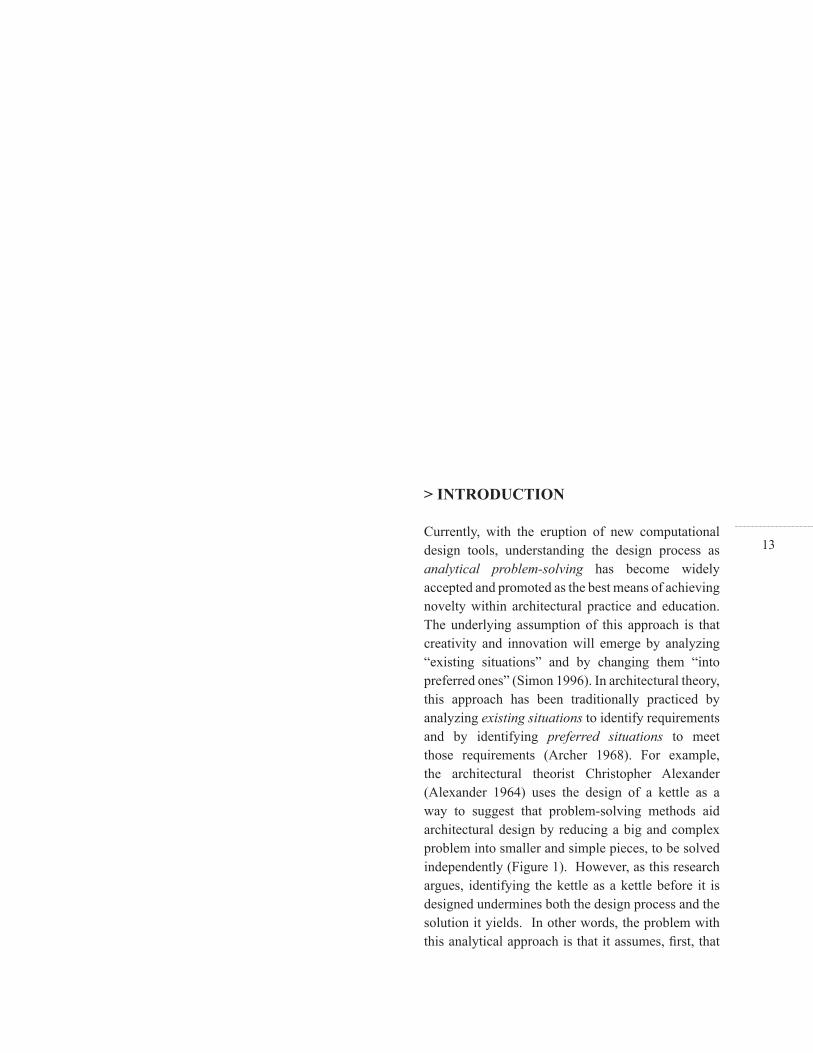
10Figure 01: Alexander -- Design as analytical problem-solving
Figure 02: Proposed model -- Designing for Uncertainty
Figure 03: Stiny -- Talking about seeing and doing
Figure 04: Greene and Webb -- Story of the Thing
Figure 05: Stiny -- Ambiguity during design conception
Figure 06: Schon’s loop -- Refl ection in Action
Figure 07: Stiny’s loop -- Calculating with Shapes
Figure 08: Stiny -- Rules and Transformations
Figure 09: Weeks -- Northwick Park Hospital
Figure 10: Archigram -- Control and Choice
Figure 11: Cook -- “What you want when you want”
Figure 12: Dutert and Cotamin -- Galerie des Machines
Figure 13: Zuk and Clark -- Kinetic architecture
Figure 14: Zuk and Clark -- Deformable architecture
Figure 15: Price -- Interaction Center (right)
Figure 16: Price -- Fun Palace (below)
Figure 17: Cook and Herron -- Control and Choice project (right)
Figure 18a: Uncertainty during design conception
Figure 18b: Uncertainty during the life of the building
Figure 19: Diagram of common concepts
Figure 20: Foerster -- Non-trivial Machine
Figure 21: Loops -- design conception and the life of the building
Figure 22: Designing for Uncertainty
Figure 23: Designing Scissor-pair Structures
Figure 24: Pinero -- Scissor-pair solution
Figure 25: Hoberman -- Scissor-pair solution
Figure 26: Centre Scissor-Pair (CSP) -- Shape and Behavior
Figure 27: Off-centre Scissor-Pair (OSP) -- Shape and Behavior
Figure 28: Angulated Scissor-Pair (ASP) -- Shape and Behavior
Figure 29: Rules applied to CSP solution
> Figures
11Figure 30: Rules applied to OSP and ASP
Figure 31: CSP, OSP and ASP three-dimensional confi gurations
Figure 32: Discovery -- Double Scissor-Pair (DSP)
Figure 33: Double Scissor-Pair (DSP) -- Shape and Behavior
Figure 34: Double Scissor-Pair three-dimensional confi guration
Figure 35: Double Scissor-Pair parametric model
Figure 36: Double Scissor-Pair physical Prototype
Figure 37: Double Scissor-Pair non-linear behavior
Figure 36: Double Scissor-Pair physical Prototype
Figure 38: Reuleaux -- Closed-chain mechanism
Figure 39: Stewart platform
Figure 40: Brooks -- Parallel levels of control
Figure 41: Robotic arm --Task-level learning
Figure 42: Zykov -- Parallel Modular Robot
Figure 43: Raffl e and Parkes –Topobo toy
Figure 44: Actuated Scissor-pair solution
Figure 45: DSP Prototype -- Deployed and S3 state
Figure 46: DSP Prototype -- Retracted and S1 state
Figure 46: DSP Prototype -- Retracted and S1 state
Figure 47: Transformations [t1] and [t2]
Figure 48: Transformation [t1] for S1-S3 combination
Figure 49: Transformation [t2] for S1-S3 combination
Figure 50: LSA actuated modules
Figure 51: LSA-SFA actuated modules
Figure 52: Modular actuation and control
Figure 53: Activity layer decomposition
Figure 54: Local actuation possibilities
Figure 55: Modular disconnection and structural discontinuity
Figure 56: Transformable Partition

12
13
> INTRODUCTION
Currently, with the eruption of new computational design tools, understanding the design process as analytical problem-solving has become widely accepted and promoted as the best means of achieving novelty within architectural practice and education. The underlying assumption of this approach is that creativity and innovation will emerge by analyzing “existing situations” and by changing them “into preferred ones” (Simon 1996). In architectural theory, this approach has been traditionally practiced by analyzing existing situations to identify requirements and by identifying preferred situations to meet those requirements (Archer 1968). For example, the architectural theorist Christopher Alexander (Alexander 1964) uses the design of a kettle as a way to suggest that problem-solving methods aid architectural design by reducing a big and complex problem into smaller and simple pieces, to be solved independently (Figure 1). However, as this research argues, identifying the kettle as a kettle before it is designed undermines both the design process and the solution it yields. In other words, the problem with this analytical approach is that it assumes, fi rst, that
14
Figure 01: Alexander -- Design as analytical problem-solving >
the object is already known before the design process begins, and, second, that the object’s requirements are certain and invariable during the object’s use and through time. In counterpoint, this thesis demonstrates that the question to ask is how the object was invented in the fi rst place. This approach thus assumes that, before the design of the object comes to fruition, the design process must face the uncertainty of what the object is going to be and the uncertainty of what the future requirements might become.
More specifi cally, this research posits that the analytical approach is not enough to “bring new things into being” (Schön 1987), and that acknowledging and using uncertainty is not only unavoidable but a necessary factor to foster innovative and creative design. Uncertainty is defi ned here from two complementary perspectives: as the uncertainty of the object during design conception and the uncertainty of future requirements during its life. With regard to the former, Donald Schön argues that architects make representations of something nonexistent, “something to be brought to reality,” in a journey, dealing with uncertainty such as unknown variables, constraints
and implications which, throughout design, may be revealed and discovered (Schön 1987). Meanwhile, with regard to the latter, Cedric Price proposes that the uncertainty of future change during the life of the design can be converted into “delight in the unknown” in relation to “the developing form of the eventual building” (Price 2003). This thesis is in line with Donald Schon’s and Cedric Price’ s ideas, since they acknowledge uncertainty and propose methods to capitalize on it. The main contribution and novelty here is to relate both these uncertainties by enriching and merging them in a synergetic and continuous process, from abstract design conception to the physical life of a building, in order to engender a new attitude towards design in architectural practice and education.
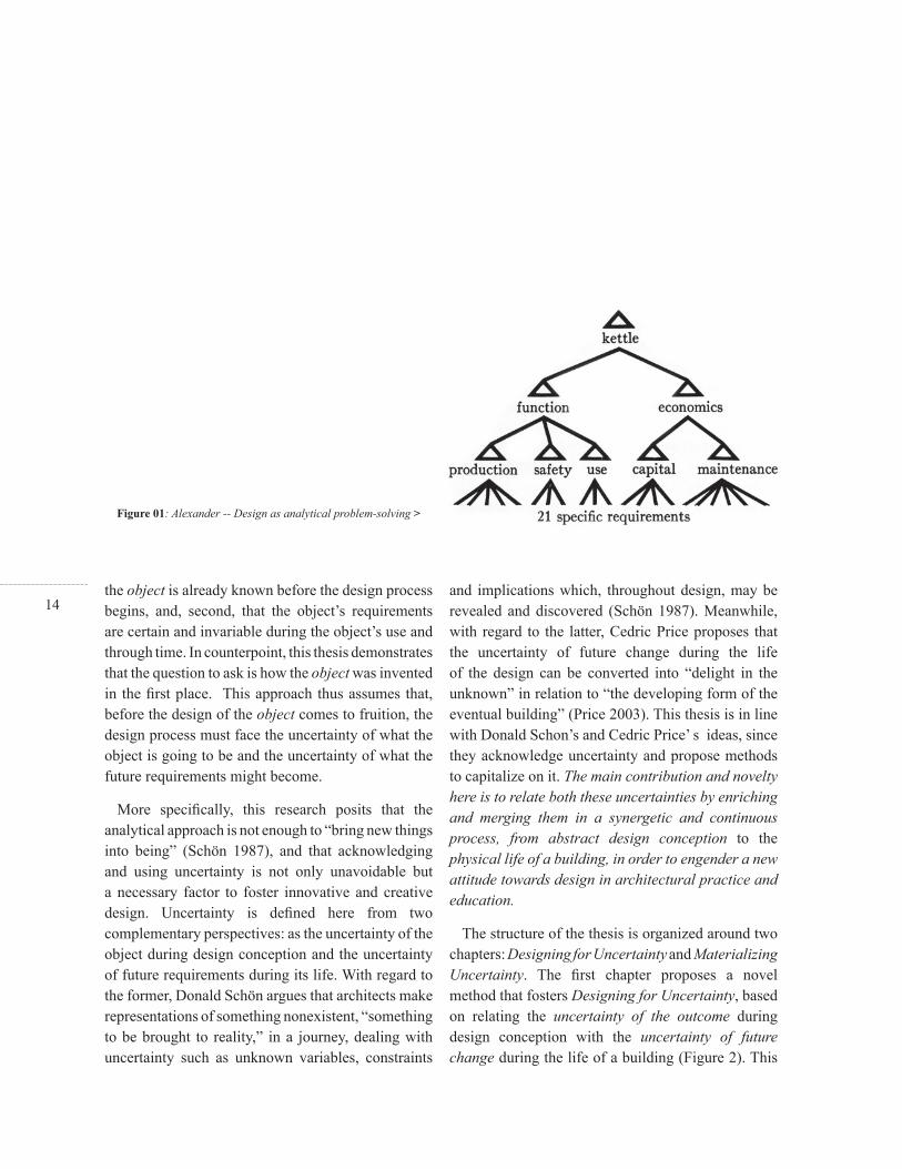
The structure of the thesis is organized around two chapters: Designing for Uncertainty and Materializing Uncertainty. The fi rst chapter proposes a novel method that fosters Designing for Uncertainty, based on relating the uncertainty of the outcome during design conception with the uncertainty of future change during the life of a building (Figure 2). This
15method is the result of looking for common factors between both uncertainties by studying the theories proposed by John Dewey, Donald Schön, George Stiny, Richard Lester and Michael Piore within the design process, and the work of Archigram, Peter Cook, Cedric Price, John Weeks, William Zuk and Roger Clark within the life of the building.
The second chapter utilizes the method of Design for Uncertainty to foster the design of novel shapes and behaviors of Scissor-pair Transformable Structures. The existing scissor-pair solutions of George Edwards, Emilio Pinero and Charles Hoberman are studied and modifi ed in order to fi nd novel shapes and behaviors. Likewise, Robotic and Artifi cial Intelligence research, as investigated through the work of Ranjan Vepa, Rodney Brooks, Patrick Winston, Erik Aboaf and Christopher Atkenson, is used as a technical background to control the robotic actuation of the proposed solution. A fi nal section provides a refl ection on the model that fosters Designing for Uncertainty, and explains the implications and problems related to the design of novel Scissor-pair Transformable Structures.
< Figure 02: Proposed model -- Designing for Uncertainty

16

17I. DESIGNING FOR UNCERTAINTY

18

19
I. DESIGNING FOR UNCERTAINTY
Architectural design, as an enterprise of bringing “new things into being” (Schön 1987), unavoidably has to assume uncertainty as a factor to be addressed and to be used. Architects make representations of something nonexistent, “something to be brought to reality” (Schön 1987), in a journey, dealing with unknown variables, constraints and implications which, throughout design, may be revealed and defi ned. Designing for Uncertainty is understood, in that sense, as the ambiguity of this new thing, the outcome, which may remain in an open-ended process of constant discovery, defi nition and re-defi nition.
The following section demonstrates how the concept of uncertainty has been addressed in design theory and in architectural discourse. While design theory explains how to assume and use uncertainty to foster the design process before “bringing the thing to reality” (Schön 1987), architectural discourse shows how uncertainty can be extended to the real world, proposing physical in-becoming buildings able to re-defi ne themselves throughout their lives. Beyond looking at both design theory and architectural discourse as separate issues, the intention is to
20actually blur the distinction between the two in order to propose a novel method that fosters Designing for Uncertainty in architecture.
It should be noted that this method, while new, is based on seminal ideas proposed in the sixties and seventies which examined the relationship between uncertainty in design theory and architectural practice. Even though it is possible to associate this research with contemporary explorations of adaptable, interactive and performative architectures (Kronenburg 2007), the aim here is to refresh the current discourse and contribute by merging old ideas with theories and technologies of today.
Historically, throughout the sixties and seventies, in parallel to the logical positivism and analytical understanding of design as “instrumental problem solving” (Simon 1996), other theories proposed a different perspective: a pragmatic notion of design as a “kind of making” (Schön 1987). Authors of that time, including Donald A. Schön and George Stiny, related the design process to John Dewey’s defi nition of inquiry as the transformation of “indeterminate
situations into determinate ones” (Dewey 1938). This notion of design, in relation to the concept of uncertainty, as well as to concepts of ambiguity and innovation, has been recognized as unavoidable and necessary to fostering innovative design. Even though with current computational tools, the logical and instrumental view of design seems to be ubiquitous, the alternative approach of creative design has gained renewed attention through, for example, Lester and Piore’s research on the interpretative process (Lester and Piore 2004).
Regarding architectural discourse, the concept of uncertainty, was likewise proposed in the sixties and seventies, yet in this case as a strong response to the fi xed and ideal architectural object proposed by Modernism. During those two decades, a new generation of architects promoted an indeterminate architecture sympathetic to uncertainty, incompleteness and emergent situations (Sadler 2005). The Archigram movement originated in London in the sixties, and the work of related architects of that time, including Cedric Price and John Weeks, created a new paradigm that infl uenced further explorations
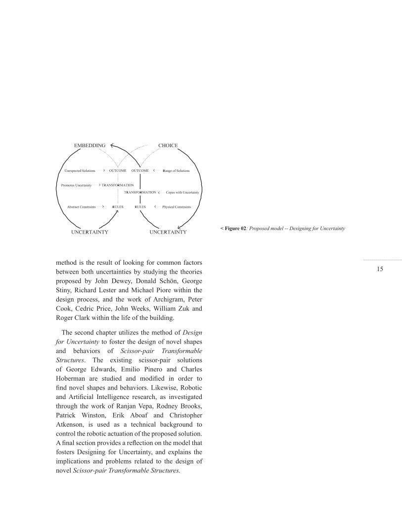
Figure 03: Stiny -- Talking about seing and doing >

21
< Figure 04: Greene and Webb -- Story of the Thing
of the topic of uncertainty. Kinetic architecture, for example, a concept introduced by William Zuk and Roger H.Clark, was supported by the idea of reducing uncertainty to the problem of “change” (Zuk and Clark 1970). Today, these explorations have lead to the notion of adaptive architecture through the use of transformable mechanisms to control and optimize the environmental and sustainable performance of the buildings (Kronenburg 2007).
The structure of this discussion is organized around these two approaches to uncertainty in design theory and architectural discourse, respectively. Whereas design theory relates to the uncertainty of the outcome during design conception, architectural discourse refers to the uncertainty of future change during the life of the building. With regard to the former, Schon’s concept of refl ection, Stiny’s notion of ambiguity (Figure 3) and Lester and Piore’s defi nition of interpretation are presented to explain how uncertainty can foster creativity and to show how the problem of terminating the design process offers novel and unexplored possibilities. With regard to the latter, Archigram’s indeterminate buildings (Figure
4), Cedric Price’s delight in the unknown and Zuk and Clark’s kinetic architecture are also described to show how to cope with the uncertainty of future change through buildings able to re-defi ne themselves throughout their lives. Finally, these two approaches to uncertainty are merged in order to propose a continuous method in which the design process is not separate to real-world conditions during the life of a building. The hypothesis here is that both processes -- design conception and the life of the building -- can inform one another and can be enriched and merged using a common and unique concept: Uncertainty. Assuming uncertainty in a synergetic and continuous process, from abstract design conception to concrete realization during the life of a building, may engender a new attitude towards design in the architecture framework: a new method that fosters Designing for Uncertainty, in which the design process does not terminate, in which buildings keep re-defi ning themselves in an open-ended loop, and in which architects may transform indeterminate situations into indeterminate solutions.

22
1. Uncertainty during Design Conception
1.1. Uncertainty, Ambiguity and Innovation
In Educating the Refl ective Practitioner, Donald A. Schön refers to the concept of uncertainty in relation to the design process. For him, design is closely related to situations of uncertainty, uniqueness and confl ict, in a process of making that involves complexity and synthesis (Schön 1987). Designers, and architects in particular, make images and representations of “something to be brought to reality,” dealing in the way with unknown and uncertain variables, constraints and consequences that, throughout designing, may be discovered and defi ned (Schön 1987). Schön relates this notion of the design process to John Dewey’s defi nition of inquiry as the transformation of “indeterminate situations into determinate ones” (Dewey 1938). A design process begins with uncertain and indeterminate situations, which, through making or “bringing new things into being,” designers may determine and impose a “coherence of their own” (Schön 1987). In the beginning, the fi nal outcome is always uncertain and designing is a continuous process of defi nition and discovery in a constant loop of construction, surprise, analysis, criticism and reconstruction.
For George Stiny uncertainty is closely related to the concept of ambiguity (Figure 5). Since it is not possible to know in advance what you are going to see and do next, ambiguity is an unavoidable factor within design process. In his book Shape, Talking about seing and Doing, Stiny explains how ambiguity causes “misunderstanding, confusion, incoherence and scandal” and yet it is not possible to be creative without it (Stiny 2006). He argues against the eternal and unchangeable logical notion of counting, standardizing and analyzing, which traditionally has attempted to reduce ambiguity as much as possible. Rather, he proposes that, assuming, using and promoting ambiguity is a method to foster creative design processes. According to Stiny, Dewey’s defi nition of inquiry also has a lot to do with design. He proposes calculating as a method to transform indeterminate and ambiguous situations --shapes-- into determinate ones. For him ambiguity allows the designer to use rules in order to transform and calculate with shapes. This process, which may be also defi ned as a loop of rule application, transformation, surprise, refl ection and re-description, enables,
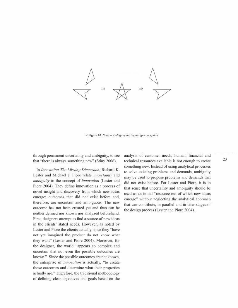
23through permanent uncertainty and ambiguity, to see that “there is always something new” (Stiny 2006).
In Innovation-The Missing Dimension, Richard K. Lester and Michael J. Piore relate uncertainty and ambiguity to the concept of innovation (Lester and Piore 2004). They defi ne innovation as a process of novel insight and discovery from which new ideas emerge: outcomes that did not exist before and, therefore, are uncertain and ambiguous. The new outcome has not been created yet and thus can be neither defi ned nor known nor analyzed beforehand. First, designers attempt to fi nd a source of new ideas in the clients’ stated needs. However, as noted by Lester and Piore the clients actually since they “have not yet imagined the product do not know what they want” (Lester and Piore 2004). Moreover, for the designer, the world “appears so complex and uncertain that not even the possible outcomes are known.” Since the possible outcomes are not known, the enterprise of innovation is actually, “to create those outcomes and determine what their properties actually are.” Therefore, the traditional methodology of defi ning clear objectives and goals based on the
analysis of customer needs, human, fi nancial and technical resources available is not enough to create something new. Instead of using analytical processes to solve existing problems and demands, ambiguity may be used to propose problems and demands that did not exist before. For Lester and Piore, it is in that sense that uncertainty and ambiguity should be used as an initial “resource out of which new ideas emerge” without neglecting the analytical approach that can contribute, in parallel and in later stages of the design process (Lester and Piore 2004).
< Figure 05: Stiny -- Ambiguity during design conception

24Even assuming that uncertainty and ambiguity foster innovative design processes, there are some additional questions to be addressed: How is the design process actually structured? And how is the creation of uncertainty promoted within the process itself?
According to Schön, the process of converting indeterminate situations into determinate ones can be defi ned as continuous endeavor of construction, surprise, refl ection and reconstruction, which he calls refl ection-in-action. The designer deals with uncertainty through refl ecting on his own actions, reframing the unexpected outcomes throughout the process and without interruption. This continuous enterprise may be related to “trial and error” methods, yet in this case refl ecting on each outcome would “set the stage for the next trial” (Schön 1987). Thus, refl ection-in-action constitutes an open-ended defi nition loop in which the designer’s refl ection on each trial is a new staring point that may reveal “new meanings and directions to the development of the artifact” (Figure 6).
For Stiny, Schön’s refl ection-in-action, and particularly the notion of reframing the unexpected, is called embedding. He defi nes embedding as a method to discover, reveal and determine, at least momentarily, whatever the designer “sees” within the ambiguity (Stiny 2006). The embedding method allows the designer to erase, forget whatever he was doing, and then describe again from scratch. Therefore the outcome is again always uncertain, and even though the process aims to transform determinate situations into determinate ones, it is always possible to look again, fi nd something new, unexpected and novel, and then describe, construct and defi ne again.
With regards to the concept of innovation, Lester and Piore also propose a pragmatic and open-ended process defi ned as interpretation. For them, interpretation is the activity out of which “something innovative emerges” (Lester and Piore 2004). Interpretation, understood as a conversation, is the method to make discoveries and new insights about the situations designers confront. Like refl ecting and embedding, interpreting is an open-ended enterprise
1.2. Open-ended Reconstruction
< Figure 06: Schon’s loop -- Refl ection in Action

25in which uncertainty and ambiguity is assumed without being eliminated. For Lester and Piore, interpretation “is not directed toward the solution of well-defi ned problem” and therefore it is not possible to say that interpretation has “an end point at all… rather, it is ongoing on time” (Lester and Piore 2004).
While our fi rst question -- how is the design process actually structured -- has been addressed, our second question -- how can we use and promote the creation of uncertainty within the process itself -- still demands further investigation. Even though Schön and Lester and Piore both propose a structure that uses uncertainty as a method to foster innovative design, they simply give a description and recognize the process without explaining how it actually works. Stiny goes a little bit further by proposing the notion of Calculating with Shapes as a way to explain the process in mathematical terms (Stiny 2006). Stiny not only recognizes uncertainty and ambiguity, but he proposes a method to create and promote these factors through the use of computation. Calculating, which for Stiny is synonymous with designing through computation, is the application of rules
and transformations to shapes (Figure 7). This process, while logical, is not limited to the initial description, since embedding allows designers to see whatever they want to see independently of the calculation already done. Rules and transformation create and promote uncertainty, ambiguity and thus the emergence of unexpected shapes, which extends Schön’s open ended process of design, understood in this case as calculation.
< Figure 07: Stiny’s loop -- Calculating with Shapes

26Even though refl ection-in-action, embedding and interpretation attempt to be open-ended enterprises, the purpose of imposing coherence on uncertainty and the aim of transforming indeterminate situations into determinate ones, would, unavoidably, imply their termination. Throughout design, the endeavor of defi nition may be open-ended, yet designers, and particularly architects, make representations of buildings but not the buildings themselves and, therefore, at some point they have to stop, choose and decide. The abstract sketches and drawings they make have to be translated to the real world, terminating the process and materializing their ideas in static and defi nite outcomes.
Schön indirectly refers to the termination of the design process through the example of the Eskimo Sculptor who “patiently carving a reindeer bone” and “examining the gradually emerging shape” fi nally discovers what was unknown and uncertain at the beginning and thus is able to exclaim: “AH, seal!” (Schön 1987). The new meanings and directions that refl ection-in-action fostered terminate when the designer is satisfi ed with the discovery of a certain
outcome. Moreover, when the sculpture of the seal is fi nished, refl ection may still be possible through interpretation, yet not in relation to action anymore. Nevertheless, Schön also notices how good jazz musicians are able to improvise and display refl ection-in-action, in a collective process of invention, in real-time. They create something new, an unpredictable piece of music, through listening one to another and responding to “surprises triggered by the inventions of the other players” (Schön 1987). In jazz, the process of design is the performance itself and therefore there is no distinction between the design and the real world piece. In spite of that fact, jazz musicians still organize their performance around a defi ned underlying structure and according to known musical fi gures. For Schön, that is the main characteristic of improvisation as creative design process, in which the new thing fi nds a coherence of its own through variation, combination and recombination of a set of fi gures in real time (Schön 1987).
Stiny proposes a slightly different notion in relation to design as an open-ended process. For him, design is never terminated and, therefore, it is always
1.3. The problem of Termination

27uncertain and ambiguous. Since it is always possible to “see that there is something new” (Stiny 2006), the building, even after construction and throughout its life, may still be interpreted in different ways by its users. For him, even though for the designer the process is terminated, it may be possible to extend uncertainty and indeterminacy to the real-world through users’ and other designers’ reinterpretation (Stiny 2006). Yet, once the shape is already built, although embedding may still be possible, calculating, describing and transforming may be diffi cult to do. Nevertheless, Stiny’s idea of users’ interpretation shows us how embedding can be extended to the real world and, thus, makes us wonder if rule application and transformation may be possible to be extended as well (Figure 8).
Since Lester and Piore’s discourse is based on product development innovation, the gap between the designer’s initial outcome and the chance to refl ect according to real-world feedback offers a different notion of incompleteness. In some situations, since innovations do not address a particular need or problem, the defi nition may become apparent only
after the product is in use. In the case of cell-phones, Lester and Piore explain how the product emerged by playing with the ambiguity of whether it was a “radio or a telephone,” and yet only after launching it to the market was it possible to appreciate that the device was used in an unpredictable manner, becoming “something that was different from either of them” and therefore new (Lester and Piore 2004).
Designers use uncertainty and ambiguity to create something new, something that did not exist before. However, these new things, as in the case of the jazz piece and the cell-phone, are far from being determinate outcomes. These creations stay in an open-ended loop, not just during conception but throughout their lives. New uncertainties emerge when the product is launched on the market, which demands constant re-description, transformation and re-construction. In the case of music and product development, designers may propose an initial outcome without knowing exactly how it is going to be performed and used. The endeavor is an open and continuous one in which designers may envision indeterminate outcomes to be adjusted and
< Figure 08: Stiny -- Rules and Transformations
28redefi ned in real time. The challenge here is to fi nd a way to engage this process in architectural design, and extend the open-ended loop of defi nition to the architectural built form. And, if this is achievable, is it then possible to foster architectural design by using uncertainty in a continuous process with no termination? To begin, it is necessary to propose a slightly different notion of design, understood here as the enterprise of transforming indeterminate situations into indeterminate physical solutions.
The concept of indeterminacy was proposed by a new generation of architects in the sixties and seventies as a way to assume and address the problem with the uncertainty of change during the life of a building. Seminal ideas, proposed in the sixties by the Archigram and its allies, promoted a novel architecture sympathetic to uncertainty, incompleteness and emergent situations (Sadler 2005). This shift in architectural discourse was further developed in the Seventies through proposing indeterminate kinetic structures able to adapt to change (Zuk and Clark 1970).
According to Simon Sadler, between 1961 and 1964, through a series of talks, unpublished papers and his project for the Northwick Park Hospital in London, John Weeks brought the word indeterminacy to architectural discourse (Sadler 2005). For Weeks, the strategy of indeterminacy was the method to “cope with the increasingly rapid growth, change and obsolescence” of buildings (Hughes 2000). He acknowledged that the requirements of future users, and thus size and unequal growth of the buildings, are uncertain factors, diffi cult to predict during the
2. Uncertainty during the Life of a Building
2.1. The Indeterminate Building

29design process. Therefore, he proposed that change and obsolescence should be assumed instead of envisioning ideal and static solutions that “would quickly prove infl exible” (Hughes 2000). He proposed an additive mode of indeterminacy, in which endless and extendable modular pavilions were able to grow linearly and thus were free to change with need throughout their lives (Figure 9).
Archigram, a movement formed in London in 1961, extended Weeks’ additive mode to a broader notion of indeterminacy by incorporating the notions of metamorphosis, choice and control (Sadler 2005). Even though the notion of indeterminacy accompanied Archigram from the outset, it was only until their 8th manifesto in 1968, when the word was formally incorporated into Archigram’s vocabulary. Archigram No.8 stated: “Oxford Dictionary defi nition: Indeterminacy: ‘Not of fi xed extent or character, vague, left doubtful.’ Archigram usage: Of varying evaluation. Not one answer. Open-endedness” (Sadler 2005). Archigram acknowledged that “buildings with no capacity to change can only become slums or ancient monuments” and thus they
envisioned an architecture in an open-ended process of determination, in a course of “in-becoming” according to their “inhabitants’ desire for continuous change” (Sadler 2005). Archigram acknowledged the uncertainty of future unknown situations by proposing incomplete buildings able to grow, transform and be controlled in real-time. As Peter Cook stated in 1970: “Architecture can be much related to the ambiguity of life. It can be throw-away or additive; it can be ad-hoc; it can be more allied to the personality and personal situation of the people who may have to use it” (Cook 1999).
The term kinetic architecture was introduced by William Zuk and Roger H.Clark in 1970. They relate several ideas, developed in the sixties in construction, engineering, planning, robotics and aerospace, which implied control and shape modifi cation through mechanical movement (Zuk and Clark 1970). Indeterminacy is understood here in relation to the uncertainty of change, of future unknown situations.
< Figure 09: Weeks -- Northwick Park Hospital

30For Zuk and Clark, architects have traditionally proposed their buildings assuming a particular problem in time, when in fact it is just an arbitrary point in a continuous process of change. For them, architecture can be defi ned as a “three-dimensional form-response to a set of pressures” and therefore kinetic architecture is the mechanical modifi cation of the shape according to the change on these pressures (Zuk and Clark 1970). Architects attempt to project this “set of pressures” into a future yet static moment in time. They then use this to dictate the solution without considering time as a continuous process of change. In contrast, Zuk and Clark proposed an architecture designed to “adapt to continuous and accelerating change” as a solution to the problem of outdated and obsolete static buildings, which have forced permanent non-sustainable and expensive recondition, tear-down or replacement. They argue that future change cannot be completely predicted nor predetermined during the design conception, and that a kinematic architecture, based on movement, variation and control, will be partially the “product of chance” (Zuk and Clark 1970).
The indeterminacy of buildings implies a different notion of the design process. Instead of the architect’s attempt to fi nd a unique, fi xed and ideal solution, assuming uncertainty fosters alternative, indeterminate and variable solutions. In order to design indeterminate buildings, the architect has to offer a range of possibilities, leaving part of the defi nition open, according to uncertain demands that occur during the life of the building.
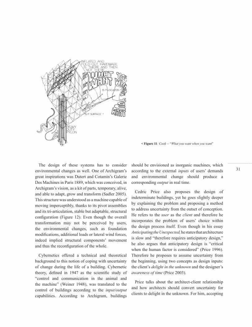
For Archigram, buildings should be conceived as live structures able to extend users’ demands through enabling control and choice (Figure 10). “What you want when you want” was one of the manifestos proposed in 1966 by Peter Cook, in the document “Control and Choice” (Figure 11). For Archigram, the determination of the environment is no longer “left in hands of the designer of the building” but it turns to the users, and thus the building is “reduced to the role of a carcass --or less” (Cook 1999). The designer’s task, here, is simply to defi ne a “conglomeration of systems, organizations and technical apparatus that permit the choice of one response out of a number of alternatives” (Cook 1999).
2.2. Designing the Lives of Buildings
< Figure 10: Archigram -- Control and Choice
31The design of these systems has to consider
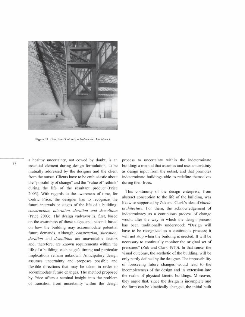
environmental changes as well. One of Archigram’s great inspirations was Dutert and Cotamin’s Galerie Des Machines in Paris 1889, which was conceived, in Archigram’s vision, as a kit of parts, temporary, alive, and able to adapt, grow and transform (Sadler 2005). This structure was understood as a machine capable of moving imperceptibly, thanks to its pivot assemblies and its tri-articulation, stable but adaptable, structural confi guration (Figure 12). Even though the overall transformation may not be perceived by users, the environmental changes, such as foundation modifi cations, additional loads or lateral wind forces, indeed implied structural components’ movement and thus the reconfi guration of the whole.
Cybernetics offered a technical and theoretical background to this notion of coping with uncertainty of change during the life of a building. Cybernetic theory, defi ned in 1947 as the scientifi c study of “control and communication in the animal and the machine” (Weiner 1948), was translated to the control of buildings according to the input/output capabilities. According to Archigram, buildings
should be envisioned as inorganic machines, which according to the external inputs of users’ demands and environmental change should produce a corresponding output in real time.
Cedric Price also proposes the design of indeterminate buildings, yet he goes slightly deeper by explaining the problem and proposing a method to address uncertainty from the outset of conception. He refers to the user as the client and therefore he incorporates the problem of users’ choice within the design process itself. Even though in his essay Anticipating the Unexpected, he states that architecture is slow and “therefore requires anticipatory design,” he also argues that anticipatory design is “critical when the human factor is considered” (Price 1996). Therefore he proposes to assume uncertainty from the beginning, using two concepts as design inputs: the client’s delight in the unknown and the designer’s awareness of time (Price 2003).
Price talks about the architect-client relationship and how architects should convert uncertainty for clients to delight in the unknown. For him, accepting
< Figure 11: Cook -- “What you want when you want”
32a healthy uncertainty, not cowed by doubt, is an essential element during design formulation, to be mutually addressed by the designer and the client from the outset. Clients have to be enthusiastic about the “possibility of change” and the “value of ‘rethink’ during the life of the resultant product”(Price 2003). With regards to the awareness of time, for Cedric Price, the designer has to recognize the future intervals or stages of the life of a building: construction, alteration, duration and demolition (Price 2003). The design endeavor is, fi rst, based on the awareness of those stages and, second, based on how the building may accommodate potential future demands. Although, construction, alteration, duration and demolition are unavoidable factors and, therefore, are known requirements within the life of a building, each stage’s timing and particular implications remain unknown. Anticipatory design assumes uncertainty and proposes possible and fl exible directions that may be taken in order to accommodate future changes. The method proposed by Price offers a seminal insight into the problem of transition from uncertainty within the design
process to uncertainty within the indeterminate building: a method that assumes and uses uncertainty as design input from the outset, and that promotes indeterminate buildings able to redefi ne themselves during their lives.
This continuity of the design enterprise, from abstract conception to the life of the building, was likewise supported by Zuk and Clark’s idea of kinetic architecture. For them, the acknowledgement of indeterminacy as a continuous process of change would alter the way in which the design process has been traditionally understood: “Design will have to be recognized as a continuous process; it will not stop when the building is erected. It will be necessary to continually monitor the original set of pressures” (Zuk and Clark 1970). In that sense, the visual outcome, the aesthetic of the building, will be only partly defi ned by the designer. The impossibility of foreseeing future changes would lead to the incompleteness of the design and its extension into the realm of physical kinetic buildings. Moreover, they argue that, since the design is incomplete and the form can be kinetically changed, the initial built
Figure 12: Dutert and Cotamin -- Galerie des Machines >

33form does not have to be correct and that, instead, the designer may offer a range of possibilities: “The architect/designer will provide a range of forms capable of meeting a range of pressure changes” (Zuk and Clark 1970). Kinetic architecture, then, may be a way to extend uncertainty from the design process to the physical in-becoming building, able to modify its shape mechanically and accommodate unknown changes (Figure 13). The design does not have to be complete and determinate, yet it should offer a range of states: an indeterminate building able to grow and transform during its life time.
In order to cope with uncertainty during the life of a building, it is necessary to envision systems able to grow and transform physically according to change. While growth is based on the addition or subtraction of components, modifying the building’s size, transformation is based on the movement and rearrangement of internal components, modifying the building’s shape. For Zuk and Clark, the main potential of a building that is able to grow, which they classify as incremental architecture, is the chance to envision a range of possible states and buildings open to “accept new, outside elements which may not have existed at the time of the original inception” (Zuk and Clark 1970). Yet, since the building is the result of the combination and addition of standard components according to fi xed rules, it is only possible to offer a range of uniform and constant growth and predictable patterns. As regards a building that is able to transform, which Zuk and Clark defi ne as deformable architecture (Figure 14), the main advantage is the chance to “meet variety functions” and thus at the time of the original design it is only necessary “to predict a range of future changes which may occur.”
2.3. Growth and Transformation
Figure 13: Zuk and Clark -- Kinetic architecture >
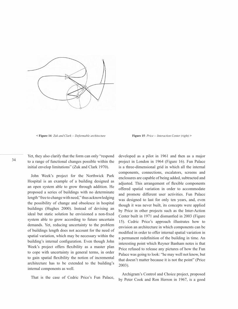
34Yet, they also clarify that the form can only “respond to a range of functional changes possible within the initial envelop limitations” (Zuk and Clark 1970).
John Week’s project for the Northwick Park Hospital is an example of a building designed as an open system able to grow through addition. He proposed a series of buildings with no determinate length “free to change with need,” thus acknowledging the possibility of change and obsolesce in hospital buildings (Hughes 2000). Instead of devising an ideal but static solution he envisioned a non-fi xed system able to grow according to future uncertain demands. Yet, reducing uncertainty to the problem of buildings length does not account for the need of spatial variation, which may be necessary within the building’s internal confi guration. Even though John Week’s project offers fl exibility as a master plan to cope with uncertainty in general terms, in order to gain spatial fl exibility the notion of incremental architecture has to be extended to the building’s internal components as well.
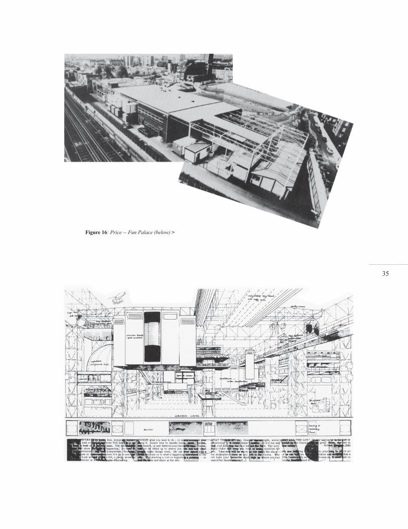
That is the case of Cedric Price’s Fun Palace,
developed as a pilot in 1961 and then as a major project in London in 1964 (Figure 16). Fun Palace is a three-dimensional grid in which all the internal components, connections, escalators, screens and enclosures are capable of being added, subtracted and adjusted. This arrangement of fl exible components offered spatial variation in order to accommodate and promote different user activities. Fun Palace was designed to last for only ten years, and, even though it was never built, its concepts were applied by Price in other projects such as the Inter-Action Center built in 1971 and dismantled in 2003 (Figure 15). Cedric Price’s approach illustrates how to envision an architecture in which components can be modifi ed in order to offer internal spatial variation in a permanent redefi nition of the building in time. An interesting point which Reyner Banham notes is that Price refused to release any pictures of how the Fun Palace was going to look: “he may well not know, but that doesn’t matter because it is not the point” (Price 2003).
Archigram’s Control and Choice project, proposed by Peter Cook and Ron Herron in 1967, is a good
< Figure 14: Zuk and Clark -- Deformable architecture Figure 15: Price -- Interaction Center (right) >
35
Figure 16: Price -- Fun Palace (below) >

36example of how to envision buildings able to transform according to uncertain change. They applied technical and theoretical knowledge from cybernetics by proposing a system able to change its shape according to users’ choice and environmental control. In this case, the internal components are not only added or subtracted according to variable needs, but are moved and rearranged affecting the building’s overall shape. There is a transformation of the whole through the movement of its internal parts. The Control and Choice project is a responsive mechanism composed of a tartan grid of tracks, which enabled the delivery of different services when needed. Moreover, this responsive mechanism is covered by a rippled skin able to expand and contract according to the internal pressures, the movement of the deliveries and the users’ demands (Figure 17).
The Control and Choice process of physical transformation is responsive to uncertain situations by offering different functional solutions. The shape variations are performed according to users’ functional demands and environmental enhancement. Yet, physical transformation might not only respond
to uncertain situations but also may be used to promote the emergence of new ones. David Greene and Michael Webb were even more radical with the notion of transformation and indeterminacy to the point of envisioning the Thing, a proposal in the context of the Living City installation in London 1963. Instead of designing a traditional building Greene and Webb proposed a placeless triangulated structure fl oating “with an unstated purpose, hopefully benign, arriving in a bleak landscape” (Sadler 2005). In this case, the project is not designed to overcame the problem of uncertainty but, on the contrary, to create and foster an even more ambiguous and emergent reality (Figure 4).
Figure 17: Cook and Herron -- Control and Choice project (right) >

37

38The purpose of the method for Designing for Uncertainty lies in its opportunity to inform and enrich both seams of architectural concerns: the abstract design conception and the physical change during the life of a building. The hypothesis is that acknowledging uncertainty in a synergetic and continuous enterprise may engender a new attitude towards architectural design. Yet, this is only possible by fi nding the means to connect these two approaches and, on the basis of this connection, propose a general and unique method that fosters Design for Uncertainty. In other words, is it possible to merge, enrich and inform both processes to create a unique and novel method, different from either of them? Before getting started, it is necessary to review the structure of both -- how they work and what concepts they use -- looking for relationships in order to connect both and inform and modify each other.
The diagram in Figure 18 shows the process during design conception and during the life of the building. For the design process, the structure begins with uncertainty and, through the application of rules and transformation based on abstract constraints, it is
possible to create unexpected solutions and therefore embed and see whatever there is to see. The process is a continuous loop of construction and reconstruction until the designer is satisfi ed with a certain outcome. The process during the life of a building uses rules and transformation based on physical constraints to generate a range of possible solutions to be determined in real-time, through users’ choice. The process is, likewise, a continuous loop, yet in this case does not have to terminate, unless the building is dismantled. Through analyzing both structures and how they work it is possible to appreciate potential associations, since their loops are organized around similar concepts. The concepts of loop of reconstruction, rules, transformation and outcome can be found in both, during design conception and during the life of the building. Even though it is possible to associate the corresponding concepts of each process to each other, they present different meanings. These different meanings are essential for the integration, since they inform and modify the abstract design conception and the physical change during the life of the building, enabling the emergence
3. Using Uncertainty
3.1. Merging Uncertainties
< Figure 18a: Uncertainty during design conception
39of a new model, different from either of them.
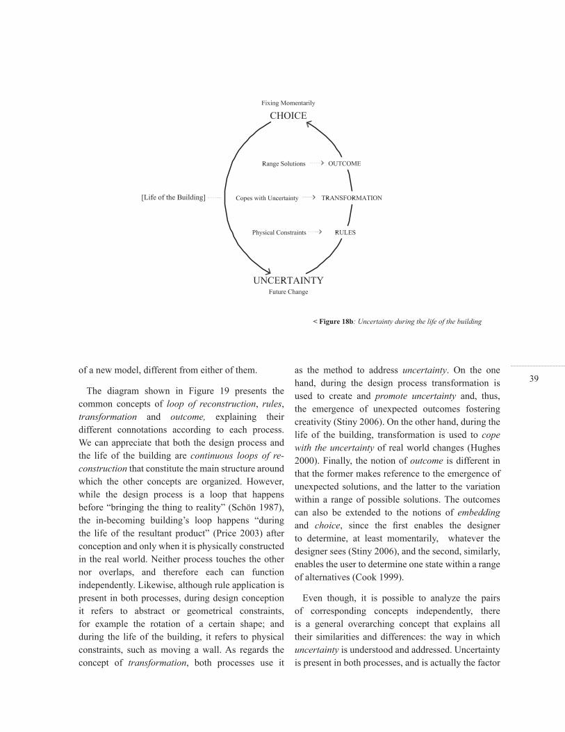
The diagram shown in Figure 19 presents the common concepts of loop of reconstruction, rules, transformation and outcome, explaining their different connotations according to each process. We can appreciate that both the design process and the life of the building are continuous loops of re-construction that constitute the main structure around which the other concepts are organized. However, while the design process is a loop that happens before “bringing the thing to reality” (Schön 1987), the in-becoming building’s loop happens “during the life of the resultant product” (Price 2003) after conception and only when it is physically constructed in the real world. Neither process touches the other nor overlaps, and therefore each can function independently. Likewise, although rule application is present in both processes, during design conception it refers to abstract or geometrical constraints, for example the rotation of a certain shape; and during the life of the building, it refers to physical constraints, such as moving a wall. As regards the concept of transformation, both processes use it
as the method to address uncertainty. On the one hand, during the design process transformation is used to create and promote uncertainty and, thus, the emergence of unexpected outcomes fostering creativity (Stiny 2006). On the other hand, during the life of the building, transformation is used to cope with the uncertainty of real world changes (Hughes 2000). Finally, the notion of outcome is different in that the former makes reference to the emergence of unexpected solutions, and the latter to the variation within a range of possible solutions. The outcomes can also be extended to the notions of embedding and choice, since the fi rst enables the designer to determine, at least momentarily, whatever the designer sees (Stiny 2006), and the second, similarly, enables the user to determine one state within a range of alternatives (Cook 1999).
Even though, it is possible to analyze the pairs of corresponding concepts independently, there is a general overarching concept that explains all their similarities and differences: the way in which uncertainty is understood and addressed. Uncertainty is present in both processes, and is actually the factor
< Figure 18b: Uncertainty during the life of the building

40that launches both loops. Yet, whereas for design conception uncertainty refers to the discovery of the new thing, which at the beginning is unknown (Stiny 2006), for the life of a building it refers to unknown future change in the environment and in users’ needs (Zuk and Clark 1970). The fact that the uncertainty during design conception is different to the one during the life of the building, affects each process’s goal, structure and inner concepts. The problem can be reduced, then, to this dual condition of uncertainty, which once solved would blur the distinctions between both processes affecting their goals, structures and inner concepts, and, therefore, would create a comprehensive and novel model. Both notions of uncertainty would complement each other in a double loop of re-construction in which each concept, rules, transformation and the outcome would be correspondingly interrelated. Yet, how is this dual understanding of uncertainty addressed? Is it possible to combine both loops to create a comprehensive model that creates uncertain new thing, coping, at the same time, uncertain future change?
Cybernetics theory, “as the science of control and communication, in the animal and the machine” (Weiner 1948), uses concepts that are similar to the ones that are used here to build the Designing for Uncertainty model: transformation, states, possibilities, control, choice and indeterminacy. Cybernetics offers us a comprehensive solution to this dual problem, in relation to the different notions of Uncertainty: on the one hand, Cybernetics proposes a functional and behavioristic approach that controls and regulates change (Ashby 1976); and on the other hand, it promotes a constructive perspective that invents reality rather than discovers it (Foerster 1981).
According to W. Ross Ashby, a machine is a determinate system able to perform a certain behavior, a transformation that follows a sequence of states according to a “well-defi ned condition that can be recognized if it occurs again” (Ashby 1976). Therefore, for him, the behavior of the machine is deterministic, since it reproduces the same transformation when the circumstances, the “facts of the changes,” are repeated. It is possible to say
3.2. Designing Buildings as Machines
Figure 19: Diagram of common concepts >
41that these circumstances are the rules that for each application may produce the same transformation, a change from one state to another in a determinate way. Therefore applying the rules generates a “set of possibilities,” a “series of positions taken in time” that are continuous defi ning “a trajectory or line of behavior” (Ashby 1976). Yet, Ashby clarifi es that, within the determinate machine, there is no ambiguity since the transformation is single-valued and, thus, a particular rule is not able to produce two different states arbitrarily. Ashby is looking for control and regulation: a system that, even though it is able to transform and offer a range of states and alternatives, is deterministic, giving us “what we want” yet following “regular and reproducible courses” (Ashby 1976).
Heinz von Foerster defi nes Ashby’s determinate machine as a trivial machine. For him the trivial machine “is the mainstay, the paradigm, underlying our ‘logical’ working conditions in almost all fi elds of study” (Segal 2001). The trivial machine is predictable, history independent and analytically deterministic: in order to understand how trivial machines work
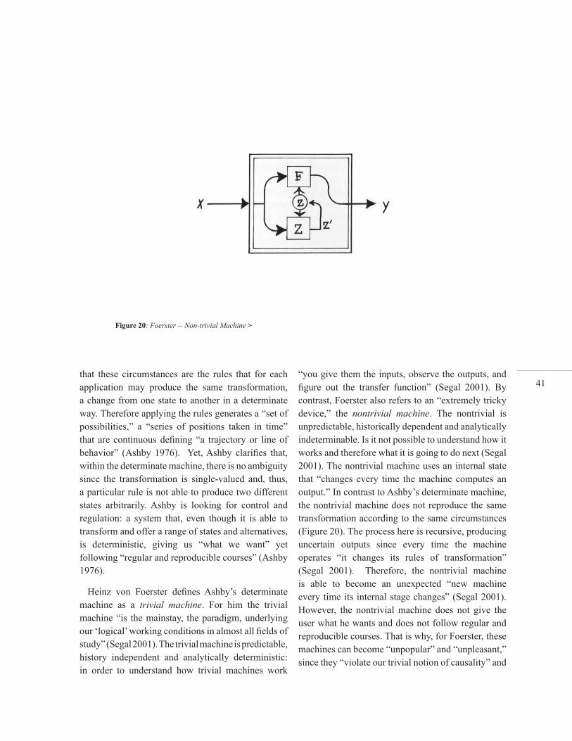
“you give them the inputs, observe the outputs, and fi gure out the transfer function” (Segal 2001). By contrast, Foerster also refers to an “extremely tricky device,” the nontrivial machine. The nontrivial is unpredictable, historically dependent and analytically indeterminable. Is it not possible to understand how it works and therefore what it is going to do next (Segal 2001). The nontrivial machine uses an internal state that “changes every time the machine computes an output.” In contrast to Ashby’s determinate machine, the nontrivial machine does not reproduce the same transformation according to the same circumstances (Figure 20). The process here is recursive, producing uncertain outputs since every time the machine operates “it changes its rules of transformation” (Segal 2001). Therefore, the nontrivial machine is able to become an unexpected “new machine every time its internal stage changes” (Segal 2001). However, the nontrivial machine does not give the user what he wants and does not follow regular and reproducible courses. That is why, for Foerster, these machines can become “unpopular” and “unpleasant,” since they “violate our trivial notion of causality” and
Figure 20: Foerster -- Non-trivial Machine >
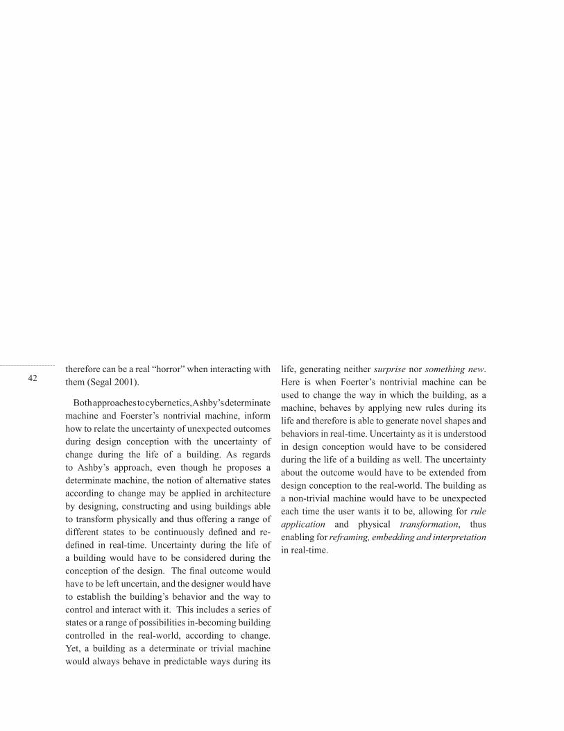
42therefore can be a real “horror” when interacting with them (Segal 2001).
Both approaches to cybernetics, Ashby’s determinate machine and Foerster’s nontrivial machine, inform how to relate the uncertainty of unexpected outcomes during design conception with the uncertainty of change during the life of a building. As regards to Ashby’s approach, even though he proposes a determinate machine, the notion of alternative states according to change may be applied in architecture by designing, constructing and using buildings able to transform physically and thus offering a range of different states to be continuously defi ned and re-defi ned in real-time. Uncertainty during the life of a building would have to be considered during the conception of the design. The fi nal outcome would have to be left uncertain, and the designer would have to establish the building’s behavior and the way to control and interact with it. This includes a series of states or a range of possibilities in-becoming building controlled in the real-world, according to change. Yet, a building as a determinate or trivial machine would always behave in predictable ways during its
life, generating neither surprise nor something new. Here is when Foerter’s nontrivial machine can be used to change the way in which the building, as a machine, behaves by applying new rules during its life and therefore is able to generate novel shapes and behaviors in real-time. Uncertainty as it is understood in design conception would have to be considered during the life of a building as well. The uncertainty about the outcome would have to be extended from design conception to the real-world. The building as a non-trivial machine would have to be unexpected each time the user wants it to be, allowing for rule application and physical transformation, thus enabling for reframing, embedding and interpretation in real-time.

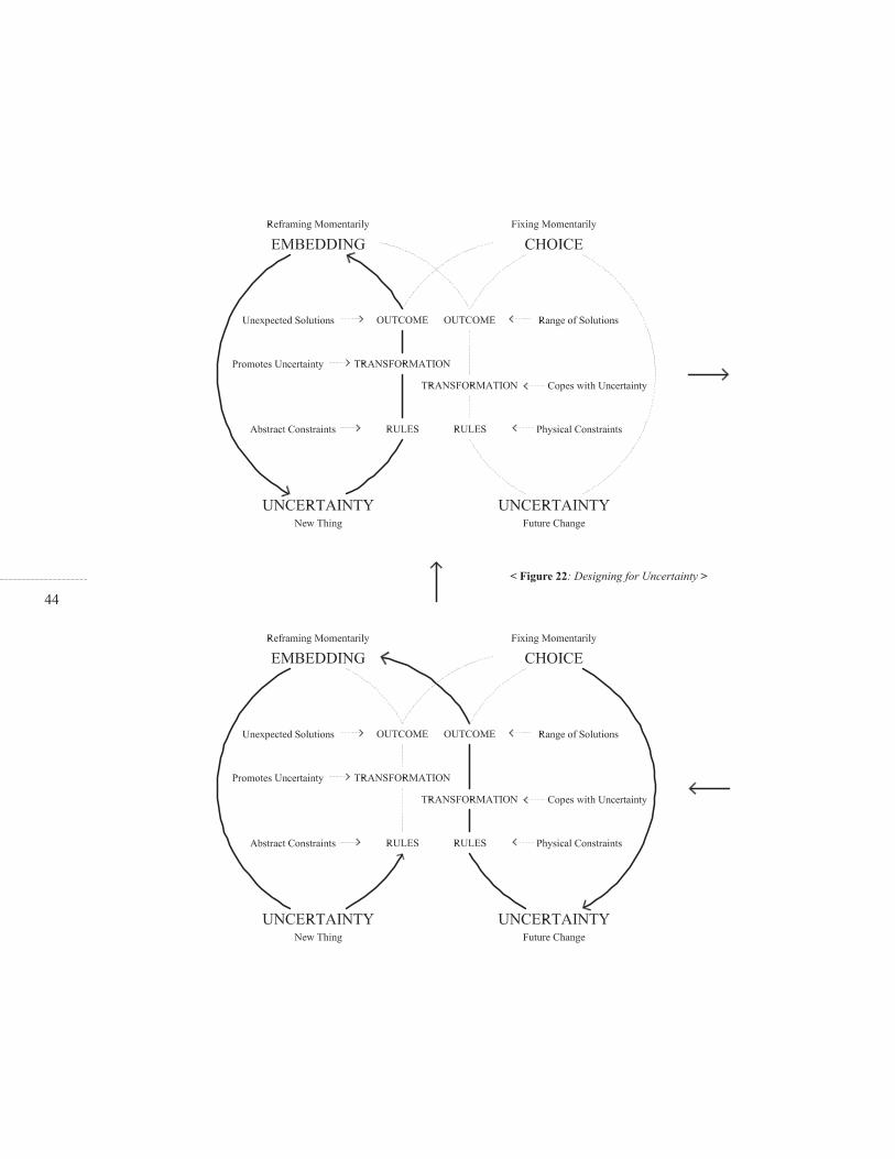
43The proposed model of Design for Uncertainty combines the loop of design conception with the loop of the life of the building (Figure 21). During design conception, the uncertainty of future change throughout the life of the building, would have to be considered; and likewise, once constructed, the building would have to enable transformation to create surprise and unexpected outcomes in real-time. The model acknowledges and promotes the features and advantages of each process, and then combines both loops by enabling switching from one loop to the other. During this process, the loops ’internal concepts inform each other, correspondingly from one loop to the other, accordingly to the following directions:
A- Uncertainty of the outcome during design conception
B- Uncertainty of future changes during design conception
C- Uncertainty of future changes during the life of a building
D- Uncertainty of the outcome during the life of a building
The model is the result of placing both loops in continuity by enabling switching from one to the other. This new comprehensive double loop fosters Designing for Uncertainty in its different manifestations, from design conception to the life of a building in a continuous and open-ended process of construction and reconstruction. As shown in Figure 22, the process launches with the design process’ loop in which directions A and B have to be considered in relation to directions C and D. Within the design process, the aim is to transform indeterminate situations into indeterminate solutions, which, once materialized, switches the loop to the the life of a building process. Here, the double loop starts to work comprehensively, switching from one loop to the other. Now, direction C retains the loop according to the uncertainty of users’ demand and environmental change, and direction D switches again to the uncertainty of the outcome but now during the life of the building.
3.3. Designing for Uncertainty
< Figure 21: Loops -- design conception and the life of the building
44
< Figure 22: Designing for Uncertainty >

45
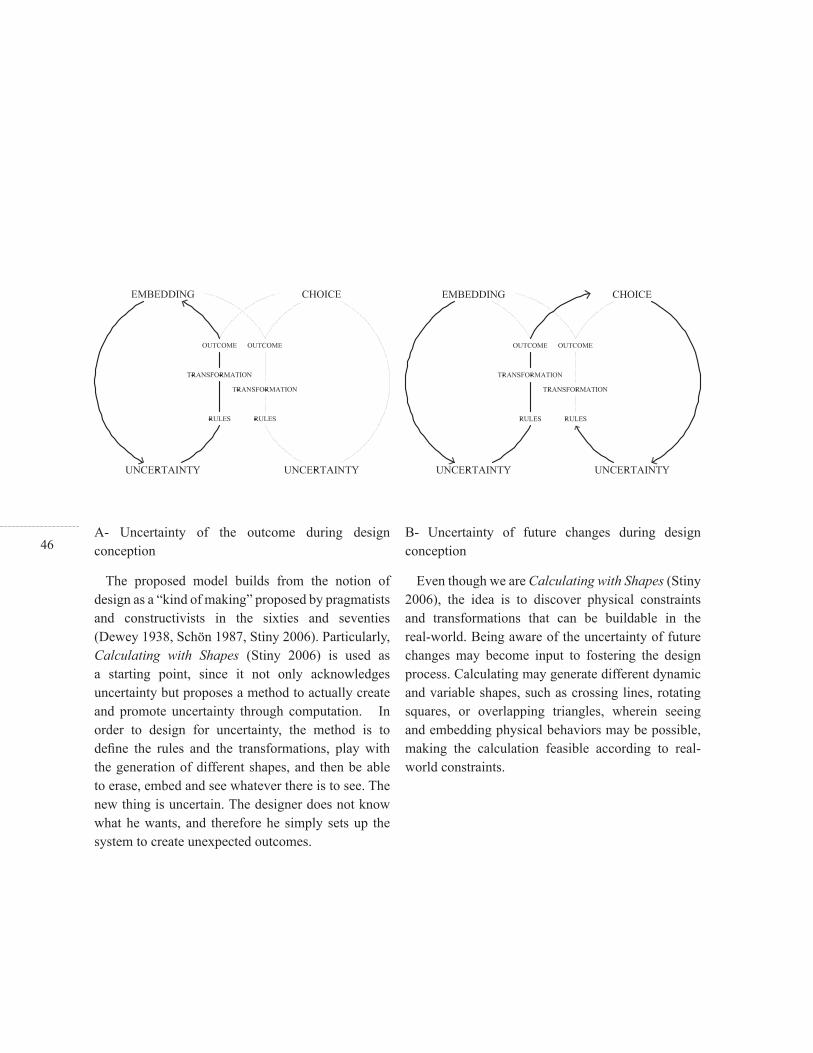
46A- Uncertainty of the outcome during design conception
The proposed model builds from the notion of design as a “kind of making” proposed by pragmatists and constructivists in the sixties and seventies (Dewey 1938, Schön 1987, Stiny 2006). Particularly, Calculating with Shapes (Stiny 2006) is used as a starting point, since it not only acknowledges uncertainty but proposes a method to actually create and promote uncertainty through computation. In order to design for uncertainty, the method is to defi ne the rules and the transformations, play with the generation of different shapes, and then be able to erase, embed and see whatever there is to see. The new thing is uncertain. The designer does not know what he wants, and therefore he simply sets up the system to create unexpected outcomes.
B- Uncertainty of future changes during design conception
Even though we are Calculating with Shapes (Stiny 2006), the idea is to discover physical constraints and transformations that can be buildable in the real-world. Being aware of the uncertainty of future changes may become input to fostering the design process. Calculating may generate different dynamic and variable shapes, such as crossing lines, rotating squares, or overlapping triangles, wherein seeing and embedding physical behaviors may be possible, making the calculation feasible according to real-world constraints.
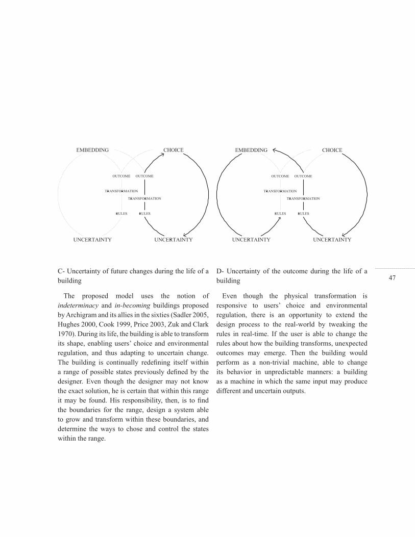
47C- Uncertainty of future changes during the life of a building
The proposed model uses the notion of indeterminacy and in-becoming buildings proposed by Archigram and its allies in the sixties (Sadler 2005, Hughes 2000, Cook 1999, Price 2003, Zuk and Clark 1970). During its life, the building is able to transform its shape, enabling users’ choice and environmental regulation, and thus adapting to uncertain change. The building is continually redefi ning itself within a range of possible states previously defi ned by the designer. Even though the designer may not know the exact solution, he is certain that within this range it may be found. His responsibility, then, is to fi nd the boundaries for the range, design a system able to grow and transform within these boundaries, and determine the ways to chose and control the states within the range.
D- Uncertainty of the outcome during the life of a building
Even though the physical transformation is responsive to users’ choice and environmental regulation, there is an opportunity to extend the design process to the real-world by tweaking the rules in real-time. If the user is able to change the rules about how the building transforms, unexpected outcomes may emerge. Then the building would perform as a non-trivial machine, able to change its behavior in unpredictable manners: a building as a machine in which the same input may produce different and uncertain outputs.

48
49II. MATERIALIZING UNCERTAINTY

50
51
II. MATERIALIZING UNCERTAINTY
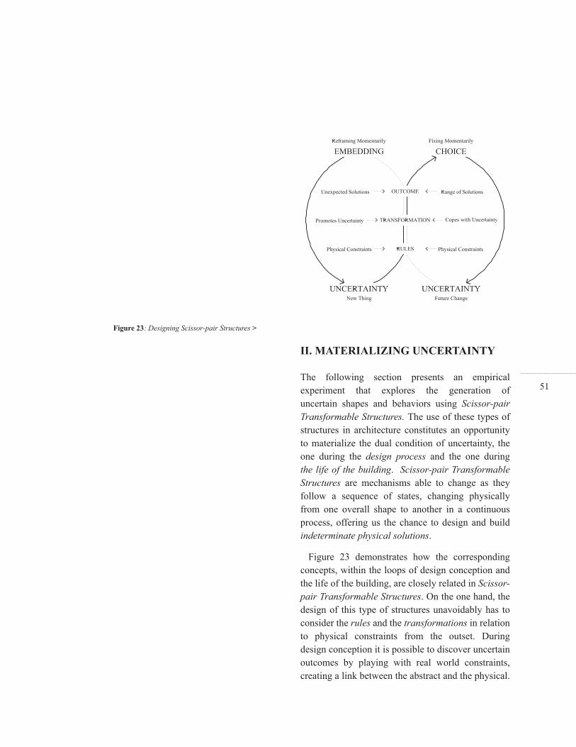
The following section presents an empirical experiment that explores the generation of uncertain shapes and behaviors using Scissor-pair Transformable Structures. The use of these types of structures in architecture constitutes an opportunity to materialize the dual condition of uncertainty, the one during the design process and the one during the life of the building. Scissor-pair Transformable Structures are mechanisms able to change as they follow a sequence of states, changing physically from one overall shape to another in a continuous process, offering us the chance to design and build indeterminate physical solutions.
Figure 23 demonstrates how the corresponding concepts, within the loops of design conception and the life of the building, are closely related in Scissor-pair Transformable Structures. On the one hand, the design of this type of structures unavoidably has to consider the rules and the transformations in relation to physical constraints from the outset. During design conception it is possible to discover uncertain outcomes by playing with real world constraints, creating a link between the abstract and the physical.
Figure 23: Designing Scissor-pair Structures >
52On the other hand, their physical transformation over time, even though it responds to uncertain change, may also be used to create uncertain outcomes in real time.
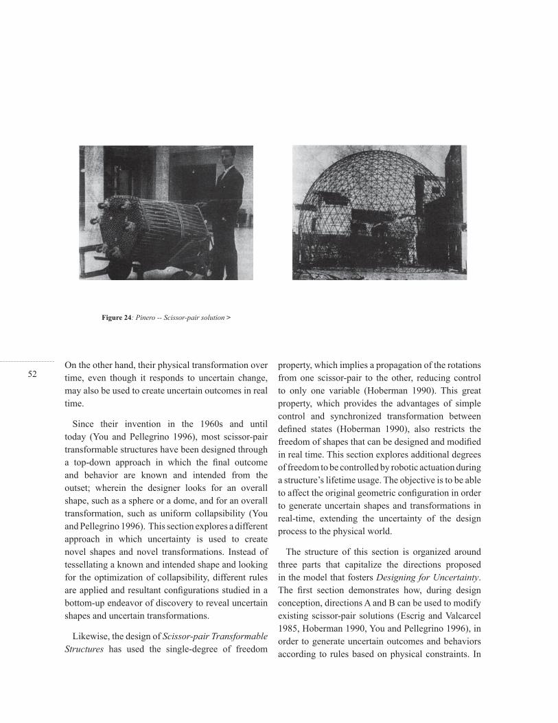
Since their invention in the 1960s and until today (You and Pellegrino 1996), most scissor-pair transformable structures have been designed through a top-down approach in which the fi nal outcome and behavior are known and intended from the outset; wherein the designer looks for an overall shape, such as a sphere or a dome, and for an overall transformation, such as uniform collapsibility (You and Pellegrino 1996). This section explores a different approach in which uncertainty is used to create novel shapes and novel transformations. Instead of tessellating a known and intended shape and looking for the optimization of collapsibility, different rules are applied and resultant confi gurations studied in a bottom-up endeavor of discovery to reveal uncertain shapes and uncertain transformations.
Likewise, the design of Scissor-pair Transformable Structures has used the single-degree of freedom
property, which implies a propagation of the rotations from one scissor-pair to the other, reducing control to only one variable (Hoberman 1990). This great property, which provides the advantages of simple control and synchronized transformation between defi ned states (Hoberman 1990), also restricts the freedom of shapes that can be designed and modifi ed in real time. This section explores additional degrees of freedom to be controlled by robotic actuation during a structure’s lifetime usage. The objective is to be able to affect the original geometric confi guration in order to generate uncertain shapes and transformations in real-time, extending the uncertainty of the design process to the physical world.
The structure of this section is organized around three parts that capitalize the directions proposed in the model that fosters Designing for Uncertainty. The fi rst section demonstrates how, during design conception, directions A and B can be used to modify existing scissor-pair solutions (Escrig and Valcarcel 1985, Hoberman 1990, You and Pellegrino 1996), in order to generate uncertain outcomes and behaviors according to rules based on physical constraints. In
Figure 24: Pinero -- Scissor-pair solution >

53this case, the study refers to mechanical single-degree of freedom structures in which once a solution is discovered it offers a deterministic range of possible shape and behaviors. Meanwhile, the second section uses Robotic and Artifi cial Intelligence background (Brooks 1991, Winston 1992, Aboaf, Drucker and Atkeson 1989) to show how to cope with uncertain real-world change and also how to produce and control uncertain behaviors in real-time. Finally, the third section shows how directions C and D can be applied to modify and tweak the Scissor-pair Transformable Structure’s geometry over time, creating unexpected shapes and behaviors in the real-world. Through sensors, actuators and microcontrollers the structure is able to learn from its own behavior, performing as a trivial machine, but it is also able to erase whatever it has already learned, performing as a nontrivial one. In this case, the study refers to robotic solutions to extend the mechanical ones by enabling additional degrees of freedom to be controlled in real-time and therefore creating new and unexpected geometrical confi gurations and behaviors.
1. Novel Shapes and Behaviors
1.1. Scissor-pair Transformable Structures
A simple transformable structure can be made from a pair of straight and rigid bars connected in the middle with a pivot or scissor hinge. This initial component is called scissor-pair and it defi nes a single-degree-of-freedom (SDF) mechanism (You and Pellegrino 1996). Through the assembly of these scissor-pair components it is possible to create two- and three-dimensional Scissor-pair Transformable Structures (Figures 24-25). The SDF property enables the control of the transformation process through the propagation of rotations from one scissor-pair to the next one and vice versa. In other words, because all scissor-pair components are linked, the rotation of one local assembly will affect the behavior of the entire structure. This principle of propagation is essential because it reduces the control mechanism to one variable, the rotation of only one component. It also determines the synchronized and smooth transformation between states (Hoberman 1990).
These types of structures have been generally used for rapidly assembled constructive systems which are able to transform their shape between two extreme states: from a compact and retracted
Figure 25: Hoberman -- Scissor-pair solution >

54state to an extended and fully deployed one. Some applications have been proposed in movable theatre structures (Pinero 1961), expandable space structures (Escrig 1985) collapsible portable shelters (Zeigler 1974), deployable domes (Hoberman, 1990, You and Pellegrino 1996) and retractable roof structures (Buhl, Jensen and Pellegrino 2004). In all these applications the main objective has been to optimize the ratio of extended and contracted length and to fi nd advantageous structural confi gurations.
The structural engineering literature covers a reasonable understanding of the shapes and behaviors that can be designed and build using the SDF property as a constraint. There are mainly three general approaches to the problem according to the shape of the rigid bars and the position of the scissor hinge: (1) The Centre Scissor-Pair (CSP) basic and traditional confi guration used by Edwards and Luckey (Edwards 1889, Luckey 1972), (2) The Off-centre Scissor-Pair (OSP) solution pioneered by Pinero, Zeigler and Escrig (Escrig and Valcarcel 1993) and (3) the Angulated Scissor-Pair (ASP) discovered by Hoberman and further developed
by You and Pellegrino (Hoberman 1990, You and Pellegrino 1996).
The Centre Scissor-Pair (CSP) is the basic confi guration for simple transformable structures. It is composed of a pair of straight and rigid bars symmetrically connected with a scissor hinge at their centre. Figure 26 shows a CSP component and how it is possible to build large CSP foldable structures through connecting edge-pivots A, B, C and D.
Even though CSP are very straightforward, they exemplify some basic principles which are important to understand more complex confi gurations. The initial principle is the propagation of rotations, which can be represented as the height H and length L among edge-pivots C and D and B and D, respectively. As shown in Figure 26, the rotation of any component is propagated from one component to the other affecting the height and length between each respective pivot-edge.
During the shape transformation, the edge-pivots follow parallel lines AB and CD; this process
Figure 26: Centre Scissor-Pair (CSP) -- Shape and Behavior >

55determines the constant transformation of the structure. In two dimensions CSP components generate linear shapes and in three dimensions, planar confi gurations. As shown in Figure 26, the behavior is synchronized and homogeneous due to the preservation of the function between retracted and extended lengths. Since the propagation from height retracted to height deployed is constant, all in-between states within the process are proportional or scaled versions of the others.
The Off-centre Scissor-Pair (OSP) (Pinero 1961) is basically a derivation of the CSP. The difference is changing one bar scissor hinge to an off-centre and therefore asymmetrical position. Figure 27 shows the OSP component in which it is possible to appreciate that the length of AO is different from the one of OD, while BO and OC remain equal.
This very simple variation results in a completely different local and overall behavior. AB and CD are no longer describing parallel lines intersecting at point O’. This local condition generates the slope S which through repetition enables the curvature of the
overall structure. Yet, the transformation is no longer homogeneous. This non-uniform behavior can be seen in Figure 27 or through the analysis of the length function in retracted and deployed states. In the OSP the functions between retracted and extended lengths are not preserved, which generates a continuous transformation from fl atness to curvature while deploying.
With regard to propagation, OSP generates two different heights: H1 and H2 among edge-pivots AB and CD, respectively. Because of this constraint, it is necessary to assemble by mirroring components alternatively. Likewise, two different lengths are created - L and L’ - whose ratio L/L’ is variable during movement. Therefore, for three-dimensional confi gurations, it is necessary to release the off-centre scissor hinge during the transformation and incorporate locking elements on defi ned states (Escrig, and Valcarcel, 1993).
The Angulated Scissor-Pair (ACS) (Hoberman 1990) is based on the modifi cation of the CSP straight bars into angulated ones. Figure 28 illustrates how
< Figure 27: Off-centre Scissor-Pair (OSP) -- Shape and Behavior
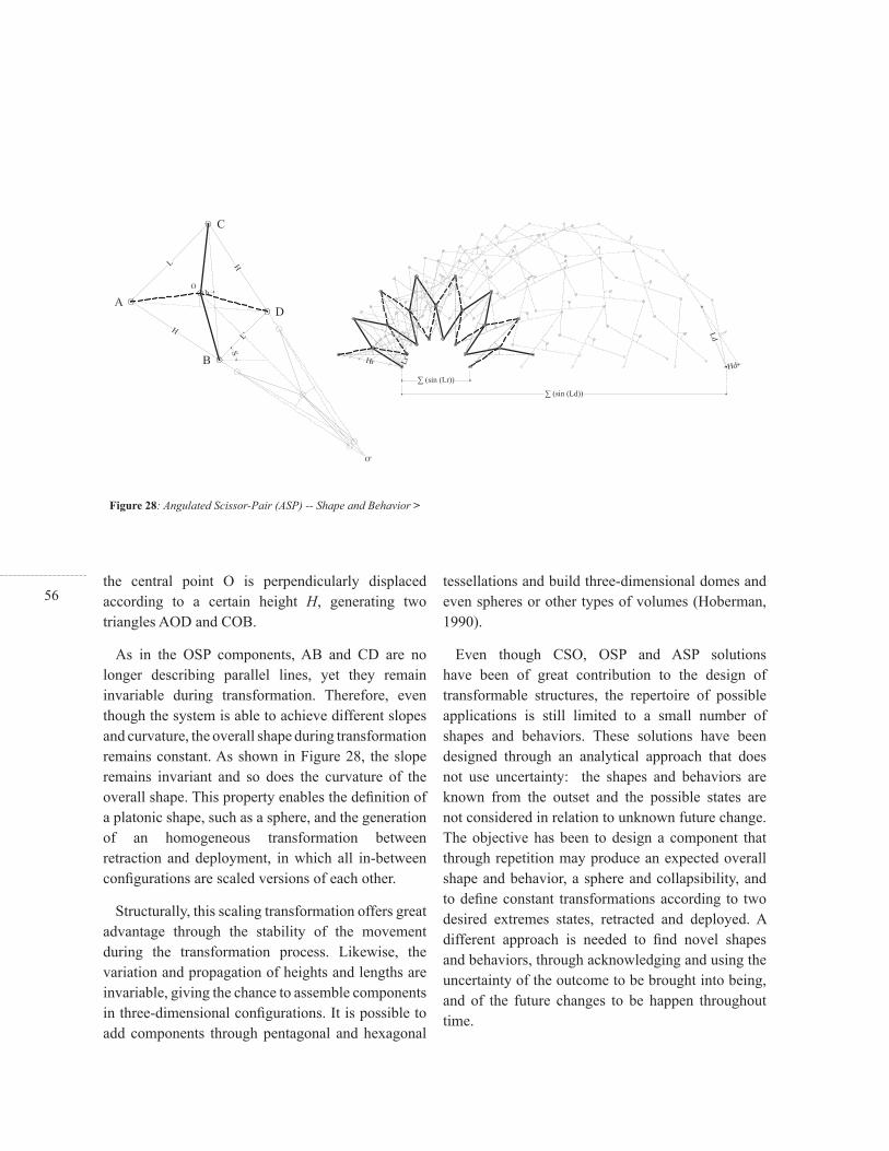
56the central point O is perpendicularly displaced according to a certain height H, generating two triangles AOD and COB.
As in the OSP components, AB and CD are no longer describing parallel lines, yet they remain invariable during transformation. Therefore, even though the system is able to achieve different slopes and curvature, the overall shape during transformation remains constant. As shown in Figure 28, the slope remains invariant and so does the curvature of the overall shape. This property enables the defi nition of a platonic shape, such as a sphere, and the generation of an homogeneous transformation between retraction and deployment, in which all in-between confi gurations are scaled versions of each other.
Structurally, this scaling transformation offers great advantage through the stability of the movement during the transformation process. Likewise, the variation and propagation of heights and lengths are invariable, giving the chance to assemble components in three-dimensional confi gurations. It is possible to add components through pentagonal and hexagonal
tessellations and build three-dimensional domes and even spheres or other types of volumes (Hoberman, 1990).
Even though CSO, OSP and ASP solutions have been of great contribution to the design of transformable structures, the repertoire of possible applications is still limited to a small number of shapes and behaviors. These solutions have been designed through an analytical approach that does not use uncertainty: the shapes and behaviors are known from the outset and the possible states are not considered in relation to unknown future change. The objective has been to design a component that through repetition may produce an expected overall shape and behavior, a sphere and collapsibility, and to defi ne constant transformations according to two desired extremes states, retracted and deployed. A different approach is needed to fi nd novel shapes and behaviors, through acknowledging and using the uncertainty of the outcome to be brought into being, and of the future changes to be happen throughout time.
Figure 28: Angulated Scissor-Pair (ASP) -- Shape and Behavior >

57
1.2. Rules and Uncertain Outcomes
In order to foster the design of uncertain and novel Scissor-pair Transformable Structures, the current solutions, CSO, OSP and ASP, are used as the starting point for experimentation. Through incorporating new rules, the objective is to generate variations and to see what types of shapes and behaviors are produced. The fi nal outcome is unknown and through a bottom-up process, in a loop of rule application, transformation and surprise, new outcomes, shapes and behaviors may be discovered. Before getting started, it is important to clarify the meanings of some concepts that are used throughout the experiment:
A- Rule: The geometric modifi cation of the scissor hinge position.
B- Outcome: The shape and behavior of the modifi ed scissor-pair, generated after the rule application.
These experiments are based on a bottom-up approach in which the intent is to understand local constraints and to project results of the overall shape. In most cases, interesting behavior in two-dimensional space may disable transversal assembly
and therefore three-dimensional confi gurations may be impossible to build. Therefore, it is essential to test local constraints and their implications for overall shape generation and behaviour. In the experiments, three constraints have been tested on the local scissor-pair, revealing the implications for overall outcome, as noted:
A-Rotation: What distance and length are produced between edge pivot assemblies when rigid bars are rotated?
B-Slope: What angle is described by pivot edges in relation to a horizontal line?
C-Propagation: How are those parameters -- rotation and slope -- propagated in two and three dimensional spaces?
There are simple rules we can apply to the existing solutions by changing the position of CSP, OSP and ASP scissor hinges. Even though all rigid bars are defi ned as identical, the way they are connected can vary according to one additional parameter. In the case of CSP and OSP, the scissor hinge position is
< Figure 29: Rules applied to CSP solution

58defi ned as a variable slider which can be fi xed at different positions. In ASP instead of an angulated rigid bar, it is possible to use a straight bar with a central and perpendicular element with variable height. These modifi cations imply the addition of another degree-of-freedom to the structure. The objective is to use this additional degree of freedom as a way to assemble identical components and use that parameter to generate variations. Therefore once assembled the system is again a single-degree-of-freedom transformable structure.
The outcomes, shapes and behaviors that can be produced through rule application are illustrated in Figures 29, 30 and 31. There are two types of scissor-pairs, S1 and S2, for each type of component. The additional parameter or slider for the scissor hinge position O’ is represented as distance d1 and d2. Retracted, deployed and in-between states are symbolized as [r], [d] and [i] respectively for each type of scissor-pair modifi cations.
In the CSP derivation the central scissor hinge is symmetrically displaced according to d1 and d2
in both rigid bars. As shown in Figure 29 the third scissor-pair is the only one that presents the S2 type. The scissor hinge modifi cation generates a variation on the height h1 and h2 between edge-pivots. Likewise, there are implications in three dimensional confi gurations as shown in Figure 31. The ‘error’ means that S2 variation in one plane entails the rotation of that assembly in the perpendicular direction. This would imply an additional degree-of-freedom of the edge-pivot, which would have to rotate on two planes: in the plane of the scissor-pair and perpendicular to it.
Figure 30 shows S1 and S2 modifi cation for the OSP confi guration. In this case d1 and d2 are applied to one rigid bar and therefore the component is no longer symmetrical as in the CSP modifi cation. The arrangement in section defi nes a curve which follows line BC. The slope of the curve is not constant during the folding process as it defi nes different heights h1, h2, h3 and h4. Even though this behavior seems interesting due to this non-constant curve transformation the different heights generate an error in three-dimensional space. As shown in Figure 31
Figure 30: Rules applied to OSP and ASP >
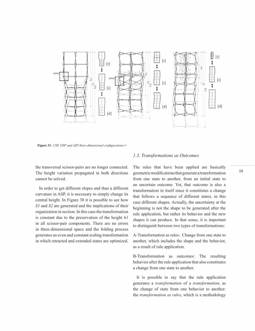
59the transversal scissor-pairs are no longer connected. The height variation propagated in both directions cannot be solved.
In order to get different slopes and thus a different curvature in ASP, it is necessary to simply change its central height. In Figure 30 it is possible to see how S1 and S2 are generated and the implications of their organization in section. In this case the transformation is constant due to the preservation of the height h1 in all scissor-pair components. There are no errors in three-dimensional space and the folding process generates an even and constant scaling transformation in which retracted and extended states are optimized.
The rules that have been applied are basically geometric modifi cations that generate a transformation from one state to another, from an initial state to an uncertain outcome. Yet, that outcome is also a transformation in itself since it constitutes a change that follows a sequence of different states, in this case different shapes. Actually, the uncertainty at the beginning is not the shape to be generated after the rule application, but rather its behavior and the new shapes it can produce. In that sense, it is important to distinguish between two types of transformations:
A-Transformation as rules: Change from one state to another, which includes the shape and the behavior, as a result of rule application.
B-Transformation as outcomes: The resulting behavior after the rule application that also constitutes a change from one state to another.
It is possible to say that the rule application generates a transformation of a transformation, as the change of state from one behavior to another: the transformation as rules, which is a methodology
1.3. Transformations as Outcomes
Figure 31: CSP, OSP and ASP three-dimensional confi gurations >
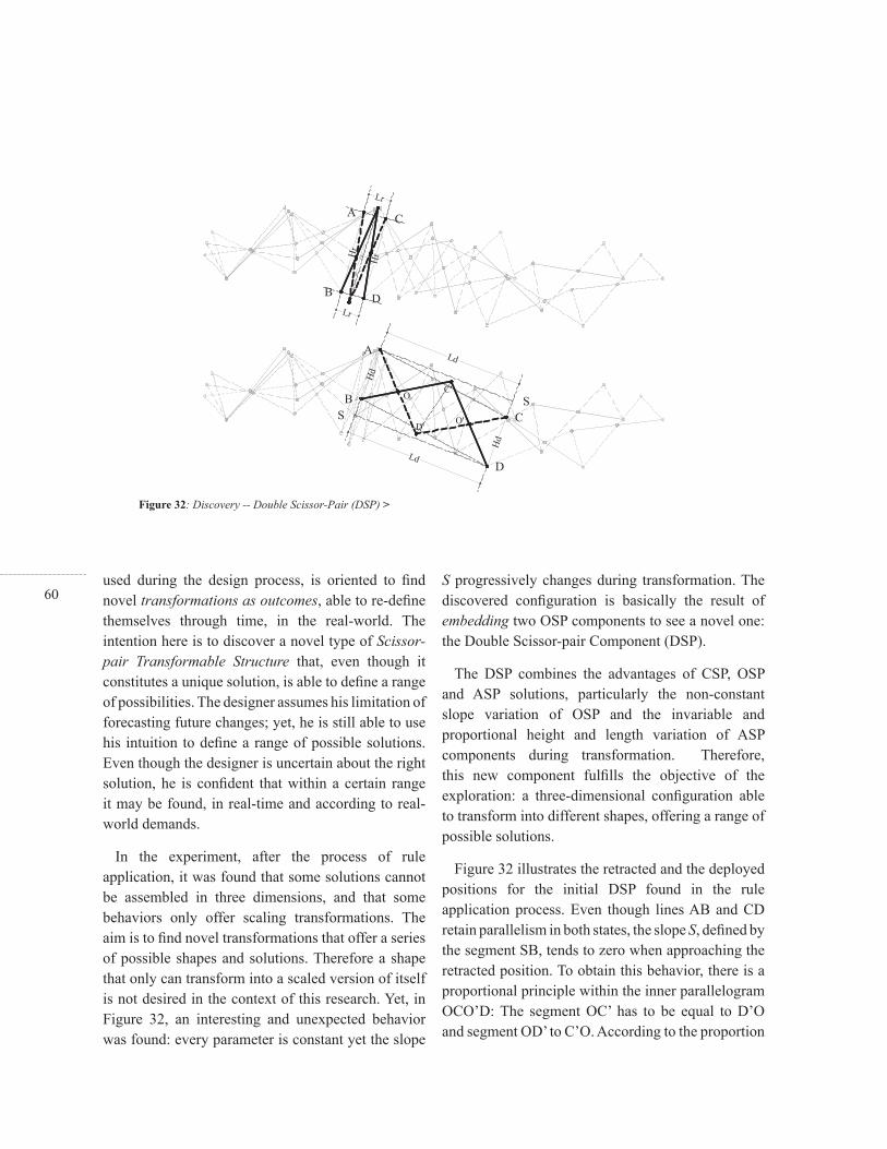
60used during the design process, is oriented to fi nd novel transformations as outcomes, able to re-defi ne themselves through time, in the real-world. The intention here is to discover a novel type of Scissor-pair Transformable Structure that, even though it constitutes a unique solution, is able to defi ne a range of possibilities. The designer assumes his limitation of forecasting future changes; yet, he is still able to use his intuition to defi ne a range of possible solutions. Even though the designer is uncertain about the right solution, he is confi dent that within a certain range it may be found, in real-time and according to real-world demands.
In the experiment, after the process of rule application, it was found that some solutions cannot be assembled in three dimensions, and that some behaviors only offer scaling transformations. The aim is to fi nd novel transformations that offer a series of possible shapes and solutions. Therefore a shape that only can transform into a scaled version of itself is not desired in the context of this research. Yet, in Figure 32, an interesting and unexpected behavior was found: every parameter is constant yet the slope
S progressively changes during transformation. The discovered confi guration is basically the result of embedding two OSP components to see a novel one: the Double Scissor-pair Component (DSP).
The DSP combines the advantages of CSP, OSP and ASP solutions, particularly the non-constant slope variation of OSP and the invariable and proportional height and length variation of ASP components during transformation. Therefore, this new component fulfi lls the objective of the exploration: a three-dimensional confi guration able to transform into different shapes, offering a range of possible solutions.
Figure 32 illustrates the retracted and the deployed positions for the initial DSP found in the rule application process. Even though lines AB and CD retain parallelism in both states, the slope S, defi ned by the segment SB, tends to zero when approaching the retracted position. To obtain this behavior, there is a proportional principle within the inner parallelogram OCO’D: The segment OC’ has to be equal to D’O and segment OD’ to C’O. According to the proportion
Figure 32: Discovery -- Double Scissor-Pair (DSP) >

61of this inner parallelogram, it is possible to defi ne several types of DSP, and therefore different slopes and transformations can be generated.
A ratio of OD/OC = 1/2 for the inner parallelogram, has been chosen for further three dimensional experimentation. Figure 33 shows the two types of double scissor-pair assembly S1 and S2 and Figure 34 how to combine them in the three-dimensional modules M1, M2 and M3. The DSP behaviour of parallelism and height-length constant variation enables perpendicular assembly in three-dimensions and thus the generation of larger transformable structures. Figure 34 illustrates how modules M1, M2 and M3 can be combined and how the slope variation enables a novel type of transformation. In the DSP transformation, in addition to scaling, the slope changes in different directions and thus the overall shape in non-uniform progression changes as well: from a fl at and compact state [r] to a twisted and deployed confi guration [d].
A DSP parametric model, using Solid Works software, was useful for analyze geometry and
behavior of SDF transformable structures. In digital space lines and points have been modelled to test local constraints and their implications in overall shape. Once the geometry and behavior are defi ned, thicknesses can then be incorporated in order to build physical transformable structures. This thickness entails an additional constraint on scissor-pair transformable structures. The problem of overlapping is added to the rotation and slope propagation initial constraints. In the physical world overlapping is not possible and therefore it is necessary to alternate rigid bars in two different planes. Figure 35 explains the two planes for rigid bar alternation and how this condition defi nes the shape of edge-pivot C1 and inner parallelogram P1 assemblies. In previous three-dimensional models edge pivots are defi ned as simple points for rotation in two directions. This point is now modelled as a cross assembly with alternate vertical and horizontal components as shown in Figure 35. Likewise, initial modules M1, M2 and M3 are modifi ed to include alternation and therefore avoid overlapping.
A physical prototype was built to test assemblies,
Figure 33: Double Scissor-Pair (DSP) -- Shape and Behavior >
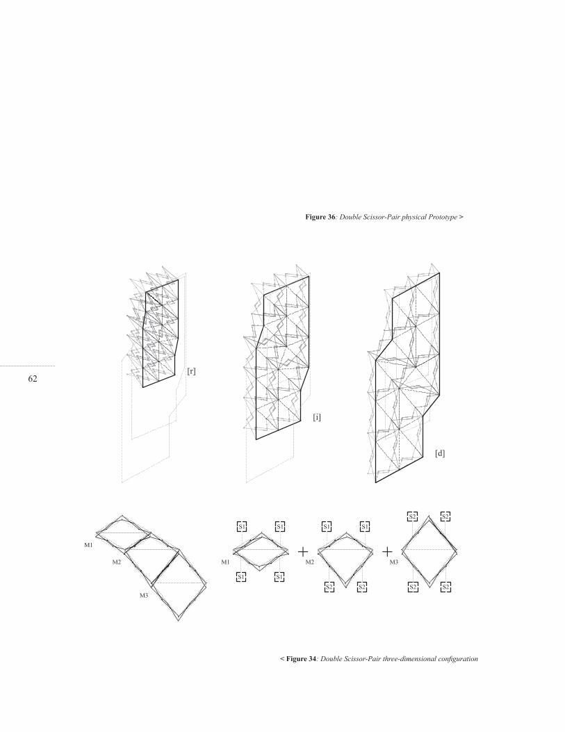
62
< Figure 34: Double Scissor-Pair three-dimensional confi guration
Figure 36: Double Scissor-Pair physical Prototype >

63
Figure 35: Double Scissor-Pair parametric model >

64thicknesses and real world performance. According to the analysis of constraints and behaviors, the physical prototype has to behave as the digital model. In that sense, there are two main concerns about initial assumptions: the rigidity of the bars and the smoothness of movement during the transformation. In order to maintain rigidity the prototype has been cut in 1/8” aluminium which is a signifi cant thickness for the scale of the model. In order to preserve smoothness, ball-bearings were included in each hinge and pivot assembly. The main concern of rigidity and smoothness is to propagate rotations and avoid the deformations of components while actuating (Figure 36).
Even though real-world behavior has been predicted through parametric model analysis, the physical prototype displays a strange behavior in the last states of deployment. The non-uniform behavior extracted from OSP changes drastically after approximately 70% of deployment. Figure 37 demonstrates this particular process. It is possible to appreciate the path described by one DSP while deploying: From the retracted state [r] towards the in-between state [i] the
edge-pivots move in a positive direction describing a predictable slope variation; yet after [i] towards deployed state [d] the process changes drastically, the edge-pivots move in a negative direction developing an extreme slope modifi cation. In spite of this unexpected and novel type of transformation, the DSP physical prototype maintains the SDF properties and advantages of previous scissor-pair transformable models. As shown in Figure 36, the DSP aluminium prototype is able to transform its shape in a vertical wall confi guration. The slope variation not only generates a twisting formal performance, but enables structural stability due to diagonal arrangement in different directions.
< Figure 37: Double Scissor-Pair non-linear behavior Figure 36: Double Scissor-Pair physical Prototype >

65
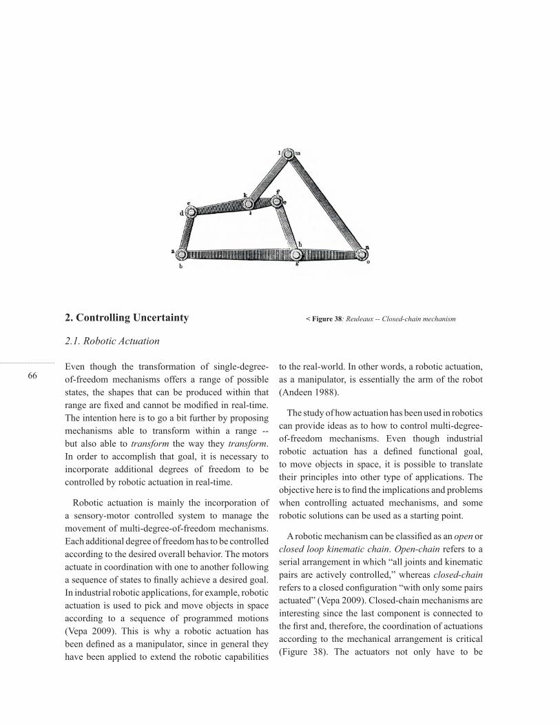
66
2. Controlling Uncertainty
2.1. Robotic Actuation
Even though the transformation of single-degree-of-freedom mechanisms offers a range of possible states, the shapes that can be produced within that range are fi xed and cannot be modifi ed in real-time. The intention here is to go a bit further by proposing mechanisms able to transform within a range -- but also able to transform the way they transform. In order to accomplish that goal, it is necessary to incorporate additional degrees of freedom to be controlled by robotic actuation in real-time.
Robotic actuation is mainly the incorporation of a sensory-motor controlled system to manage the movement of multi-degree-of-freedom mechanisms. Each additional degree of freedom has to be controlled according to the desired overall behavior. The motors actuate in coordination with one to another following a sequence of states to fi nally achieve a desired goal. In industrial robotic applications, for example, robotic actuation is used to pick and move objects in space according to a sequence of programmed motions (Vepa 2009). This is why a robotic actuation has been defi ned as a manipulator, since in general they have been applied to extend the robotic capabilities
to the real-world. In other words, a robotic actuation, as a manipulator, is essentially the arm of the robot (Andeen 1988).
The study of how actuation has been used in robotics can provide ideas as to how to control multi-degree-of-freedom mechanisms. Even though industrial robotic actuation has a defi ned functional goal, to move objects in space, it is possible to translate their principles into other type of applications. The objective here is to fi nd the implications and problems when controlling actuated mechanisms, and some robotic solutions can be used as a starting point.
A robotic mechanism can be classifi ed as an open or closed loop kinematic chain. Open-chain refers to a serial arrangement in which “all joints and kinematic pairs are actively controlled,” whereas closed-chain refers to a closed confi guration “with only some pairs actuated” (Vepa 2009). Closed-chain mechanisms are interesting since the last component is connected to the fi rst and, therefore, the coordination of actuations according to the mechanical arrangement is critical (Figure 38). The actuators not only have to be
< Figure 38: Reuleaux -- Closed-chain mechanism
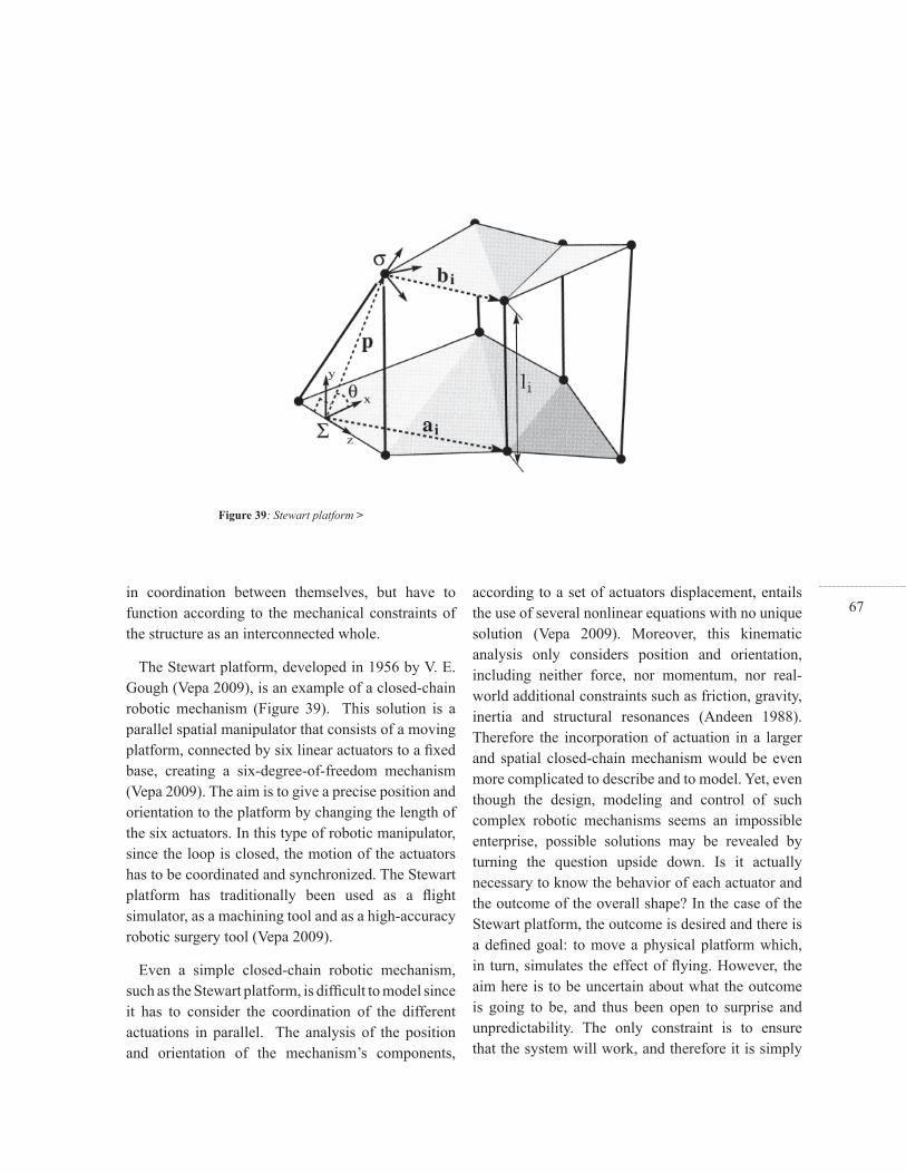
67in coordination between themselves, but have to function according to the mechanical constraints of the structure as an interconnected whole.
The Stewart platform, developed in 1956 by V. E. Gough (Vepa 2009), is an example of a closed-chain robotic mechanism (Figure 39). This solution is a parallel spatial manipulator that consists of a moving platform, connected by six linear actuators to a fi xed base, creating a six-degree-of-freedom mechanism (Vepa 2009). The aim is to give a precise position and orientation to the platform by changing the length of the six actuators. In this type of robotic manipulator, since the loop is closed, the motion of the actuators has to be coordinated and synchronized. The Stewart platform has traditionally been used as a fl ight simulator, as a machining tool and as a high-accuracy robotic surgery tool (Vepa 2009).
Even a simple closed-chain robotic mechanism, such as the Stewart platform, is diffi cult to model since it has to consider the coordination of the different actuations in parallel. The analysis of the position and orientation of the mechanism’s components,
according to a set of actuators displacement, entails the use of several nonlinear equations with no unique solution (Vepa 2009). Moreover, this kinematic analysis only considers position and orientation, including neither force, nor momentum, nor real-world additional constraints such as friction, gravity, inertia and structural resonances (Andeen 1988). Therefore the incorporation of actuation in a larger and spatial closed-chain mechanism would be even more complicated to describe and to model. Yet, even though the design, modeling and control of such complex robotic mechanisms seems an impossible enterprise, possible solutions may be revealed by turning the question upside down. Is it actually necessary to know the behavior of each actuator and the outcome of the overall shape? In the case of the Stewart platform, the outcome is desired and there is a defi ned goal: to move a physical platform which, in turn, simulates the effect of fl ying. However, the aim here is to be uncertain about what the outcome is going to be, and thus been open to surprise and unpredictability. The only constraint is to ensure that the system will work, and therefore it is simply
Figure 39: Stewart platform >

68necessary to set up a system with the capability to learn from its own behavior and according to real-world input.
In the paper “Intelligence without Representation” Rodney A. Brooks proposes the concept of Subsumption Architecture. For him representing the world is the “wrong unit of abstraction,” and it turns out to be better “to use the world as its own model” (Brooks 1991). He proposes the building of autonomous robotic agents which he calls Creatures. For Brooks, a Creature has to be designed “to cope with changes in its dynamic environment,” and to do something in the world, “it should have a purpose in being” (Brooks 1991). Likewise a Creature “should be able to maintain multiple goals” in parallel in order to “adapt to surroundings and capitalize on fortuitous circumstances.” That is what the concept of Subsumption Architecture actually means: a methodology of tasks decomposition in which multiple goals are organized in layers, with no preconceived “programs or plans to follow for specifi c mission.” The Creature simply moves around. Its different tasks work in parallel, avoiding objects, wandering and exploring new destinations according to uncertain situations “it fi nds itself in” (Brooks 1991).
2.2. Learning from the Real-World
Figure 40: Brooks -- Parallel levels of control >
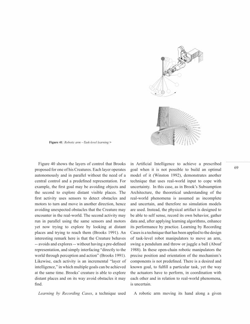
69Figure 40 shows the layers of control that Brooks
proposed for one of his Creatures. Each layer operates autonomously and in parallel without the need of a central control and a predefi ned representation. For example, the fi rst goal may be avoiding objects and the second to explore distant visible places. The fi rst activity uses sensors to detect obstacles and motors to turn and move in another direction, hence avoiding unexpected obstacles that the Creature may encounter in the real-world. The second activity may run in parallel using the same sensors and motors yet now trying to explore by looking at distant places and trying to reach them (Brooks 1991). An interesting remark here is that the Creature behaves -- avoids and explores -- without having a pre-defi ned representation, and simply interfacing “directly to the world through perception and action” (Brooks 1991). Likewise, each activity is an incremental “layer of intelligence,” in which multiple goals can be achieved at the same time. Brooks’ creature is able to explore distant places and on its way avoid obstacles it may fi nd.
Learning by Recording Cases, a technique used
in Artifi cial Intelligence to achieve a prescribed goal when it is not possible to build an optimal model of it (Winston 1992), demonstrates another technique that uses real-world input to cope with uncertainty. In this case, as in Brook’s Subsumption Architecture, the theoretical understanding of the real-world phenomena is assumed as incomplete and uncertain, and therefore no simulation models are used. Instead, the physical artifact is designed to be able to self sense, record its own behavior, gather data and, after applying learning algorithms, enhance its performance by practice. Learning by Recording Cases is a technique that has been applied to the design of task-level robot manipulators to move an arm, swing a pendulum and throw or juggle a ball (Aboaf 1988). In these open-chain robotic manipulators the precise position and orientation of the mechanism’s components is not predefi ned. There is a desired and known goal, to fulfi ll a particular task, yet the way the actuators have to perform, in coordination with each other and in relation to real-world phenomena, is uncertain.
A robotic arm moving its hand along a given
Figure 41: Robotic arm --Task-level learning >
70trajectory is a good illustration of the methodology used in the Learning by Recording Cases technique. In order to reach its goal, the parameters that need to be predicted are the angle and torque variation for each pivot actuator. Even though there are simple mathematical models to calculate the rotation, the torque is diffi cult to compute due to additional real-world factors. The solution is to record real-world behavior and to learn through iteration (Winston 1992). The robotic arm begins with random and erratic movements. Consequently, data is recorded and then related to the desired trajectory. Learning Algorithms are used to make classifi cation and predictions and then, by iterating the whole process, which is called practice, the robotic arm is able to progressively improve its performance reaching a satisfactory result (Aboaf 1988). This learning process seeks the optimization of a known and desired overall behavior. There is neither reliable initial data nor models for simulation, yet the learning process seeks a satisfactory performance according to a predictable goal, such as moving an arm along a given trajectory. Even though the overall behavior
is known, the rotation of each actuator and how they interact with each other is uncertain. The system is designed for uncertainty through setting up a system able to defi ne and re-defi ne its behavior in the real-world through practice.
Subsumption Architecture and Learning by Recording Cases illustrate how to control robotic actuation through learning and interfacing directly to the real-world. This technique can be used to design multi-degree-of-freedom closed-chain mechanisms, in which the behaviors can be a product of perception and action in real-time. The intention is to control the actuation of spatial closed-chain mechanism and therefore the challenge now is fi nding a method to extend these robotic techniques into larger confi gurations.
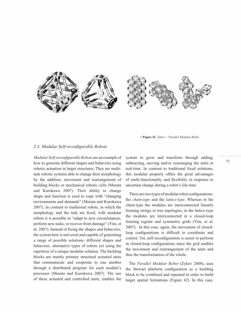
71Modular Self-reconfi gurable Robots are an example of how to generate different shapes and behaviors using robotic actuation in larger structures. They are multi-task robotic systems able to change their morphology by the addition, movement and rearrangement of building blocks or mechanical robotic cells (Murata and Kurokawa 2007). Their ability to change shape and function is used to cope with “changing environments and demands” (Murata and Kurokawa 2007). In contrast to traditional robots, in which the morphology and the task are fi xed, with modular robots it is possible to “adapt to new circumstances, perform new tasks, or recover from damage” (Yim, et al. 2007). Instead of fi xing the shapes and behaviors, the system here is universal and capable of generating a range of possible solutions: different shapes and behaviors, alternative types of robots yet using the repetition of a unique modular solution. The building blocks are mainly primary structural actuated units that communicate and cooperate to one another through a distributed program for each module’s processor (Murata and Kurokawa 2007). The use of these actuated and controlled units, enables the
system to grow and transform through adding, subtracting, moving and/or rearranging the units in real-time. In contrast to traditional fi xed solutions, this modular property offers the great advantages of multi-functionality and fl exibility in response to uncertain change during a robot’s life time.
There are two types of modular robot confi gurations: the chain-type and the lattice-type. Whereas in the chain-type the modules are interconnected linearly forming strings or tree topologies, in the lattice-type the modules are interconnected in a closed-loop forming regular and symmetric grids (Yim, et al. 2007). In this case, again, the movement of closed-loop confi gurations is diffi cult to coordinate and control. Yet, self-reconfi guration is easier to perform in closed-loop confi gurations since the grid enables the movement and rearrangement of the units and thus the transformation of the whole.
The Parallel Modular Robot (Zykov 2008), uses the Stewart platform confi guration as a building block to be combined and repeated in order to build larger spatial formations (Figure 42). In this case,
2.3. Modular Self-reconfi gurable Robots
< Figure 42: Zykov -- Parallel Modular Robot

72the lattice-type and the chain-type are combined to use the advantages of each: dexterous motion control and coordination in chain-type, arm or leg-like confi gurations, and self-confi guration by the units’ movements and rearrangements in the lattice-type, grid or mesh-like confi gurations. An interesting feature of the Parallel Modular Robot solution is that the unit is also able to modify its shape and its behavior. Instead of simply using rearrangement as the source of overall shape transformation, the parallel robotic unit, based on the Stewart platform, is able to transform itself. In this modular robotic solution, the overall shape transformation, the modifi cation of shapes and behaviors, can be the result of local actuations instead of component rearrangement.
The Topobo Toy (Raffl e, 2004), exemplifi es how to control modular robotic actuation using a similar methodology to the one used in the Learning by Recording Cases technique (Figure 43). This solution is basically a modular system that enables the design of different confi gurations and behaviors in real-time. In contrast to traditional modular robotic applications, the range of possible solutions is not predefi ned
but recorded in real-time. It uses a decentralized control system that records the movement of each local assembly in order to sense human input. It then reproduces that input as a physical output, and in turn generates new transformations any time the user wants to. Through adding modules, recording and playing in real-time, it allows the design of different confi gurations and behaviors. For example, it is possible to build a shape, such as a dog, and record a desired behavior, such as the movement of the dog’s legs. The system acknowledges the shapes and behaviors as uncertain since it does not set the goals beforehand, and rather simply offers a method to create and discover new possibilities in real-time.
While the Parallel Modular Robot shows how to transform larger closed-chain mechanisms by local actuation, the Topobo Toy illustrates how to create shapes and behaviors in real-time. On the one hand, overall transformations can be generated by the local transformation of each module. The aim is to build larger robotic structures through the addition of modules able to transform independently and in relation to one another. On the other hand, it is
Figure 43: Raffl e and Parkes --Topobo toy >
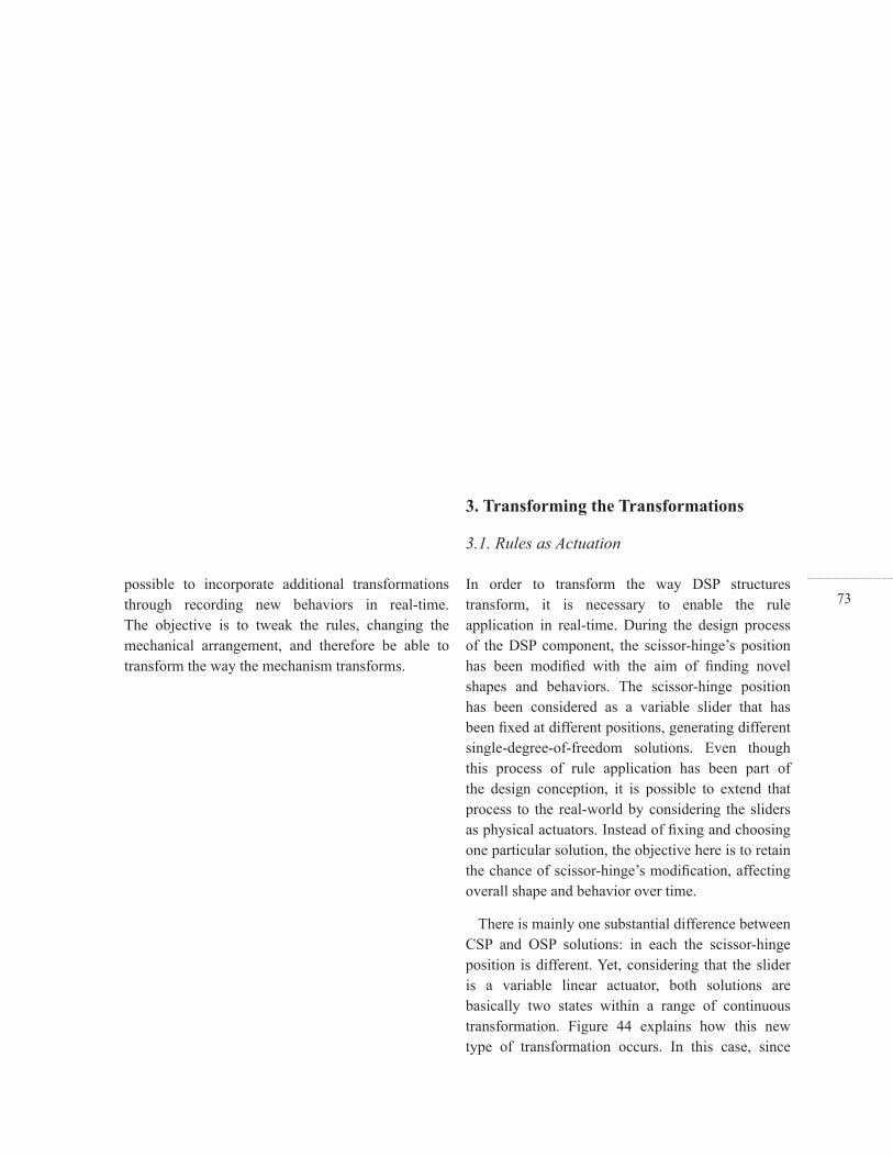
73possible to incorporate additional transformations through recording new behaviors in real-time. The objective is to tweak the rules, changing the mechanical arrangement, and therefore be able to transform the way the mechanism transforms.
In order to transform the way DSP structures transform, it is necessary to enable the rule application in real-time. During the design process of the DSP component, the scissor-hinge’s position has been modifi ed with the aim of fi nding novel shapes and behaviors. The scissor-hinge position has been considered as a variable slider that has been fi xed at different positions, generating different single-degree-of-freedom solutions. Even though this process of rule application has been part of the design conception, it is possible to extend that process to the real-world by considering the sliders as physical actuators. Instead of fi xing and choosing one particular solution, the objective here is to retain the chance of scissor-hinge’s modifi cation, affecting overall shape and behavior over time.
There is mainly one substantial difference between CSP and OSP solutions: in each the scissor-hinge position is different. Yet, considering that the slider is a variable linear actuator, both solutions are basically two states within a range of continuous transformation. Figure 44 explains how this new type of transformation occurs. In this case, since
3. Transforming the Transformations
3.1. Rules as Actuation

74CSP and OSP are not fi xed solutions but states within DSP’s transformation, they are defi ned as S1 -- state one -- and S3 -- state three --, respectively. While in the initial state, S1, the actuated scissor-hinge is positioned at the rigid bar’s center, in the fi nal state, S3, it is positioned off-center. By dividing the rigid bar into 8 equivalent units, noted as X, it is possible to express each state, S1 and S3, as 4X/4X and 6X/2X, respectively, and likewise incorporate an in-between state S2, expressed as 5X/3X. Yet, these units are only a method to illustrate the process, which is actually a continuous transformation with no divisions.
Since the DSP solution is actually two OSP components, it is necessary to incorporate two linear actuators. The objective here is to generate new shapes and behaviors in real-time, extending the design process to the life of the building. Therefore, the system has to be capable of sensing human input and reproducing it as physical output. According to those capabilities, the actuators have to fulfi ll the following initial requirements:
A-Sensing: In Passive mode the actuators have to
work as sensors to record the rotation, defi ned by the user in real-time.
B-Actuating: In Active mode the actuators have to reproduce the transformation, recorded throughout the sensing process.
Figure 44 shows states S1, S2 and S3 as abstract lines and as the physical actuated DSP as well. A servo mechanism is used to fulfi ll the requirements of sensing and actuating by connecting a servo motor to a two-member-linkage and a sliding member. This system works as a Linear Servo Actuator (LSA) that uses the servo’s internal potentiometer to sense, and the servo’s DC motor to actuate. This digital operation is controlled by an Arduino microcontroller that is embedded in the structure.
Even though a traditional servo motor works, by default, in Active mode, the LSM is capable of sensing during Passive mode as well. The scissor-hinge’s position can be modifi ed in real-time since, during Passive mode, the DC motor is turned off (Figures 45-46). Yet the internal potentiometer can be
< Figure 44: Actuated Scissor-pair solution >

75
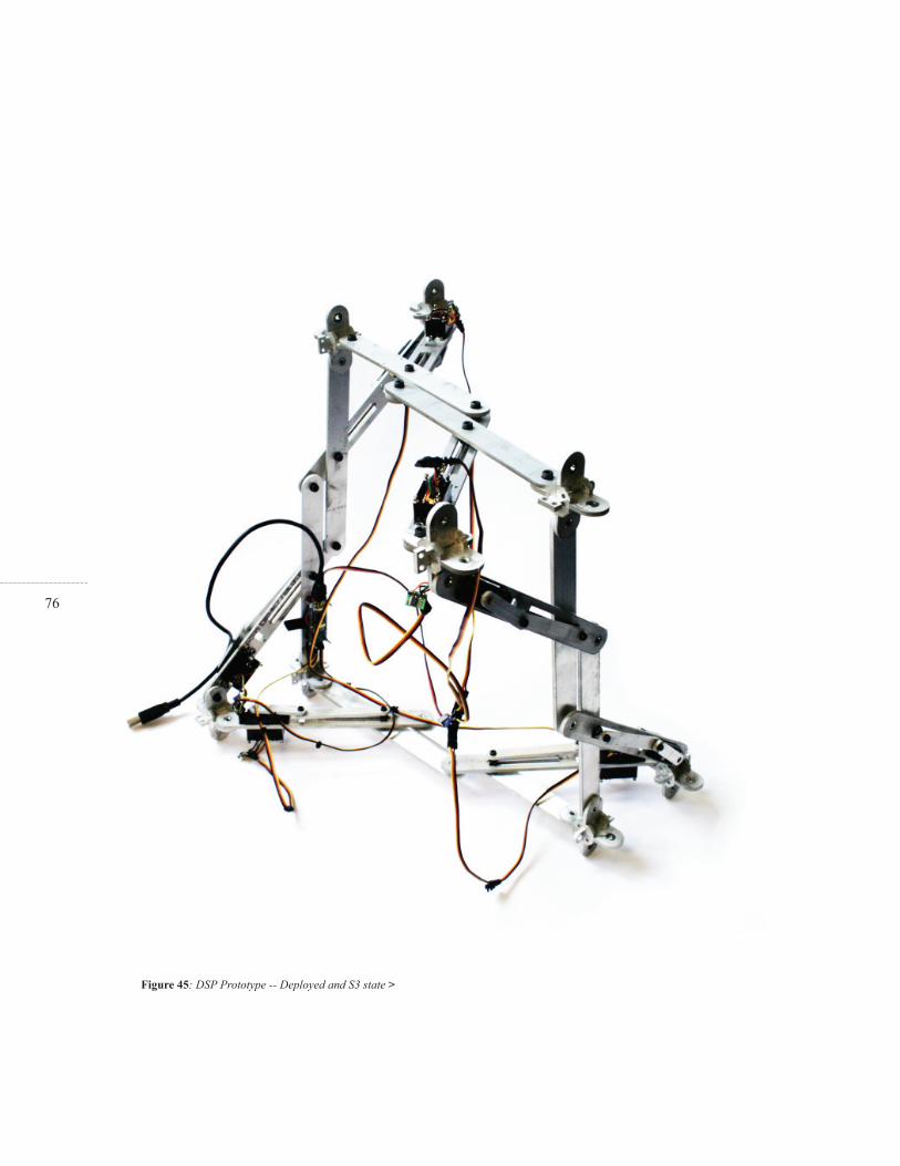
76
Figure 45: DSP Prototype -- Deployed and S3 state >
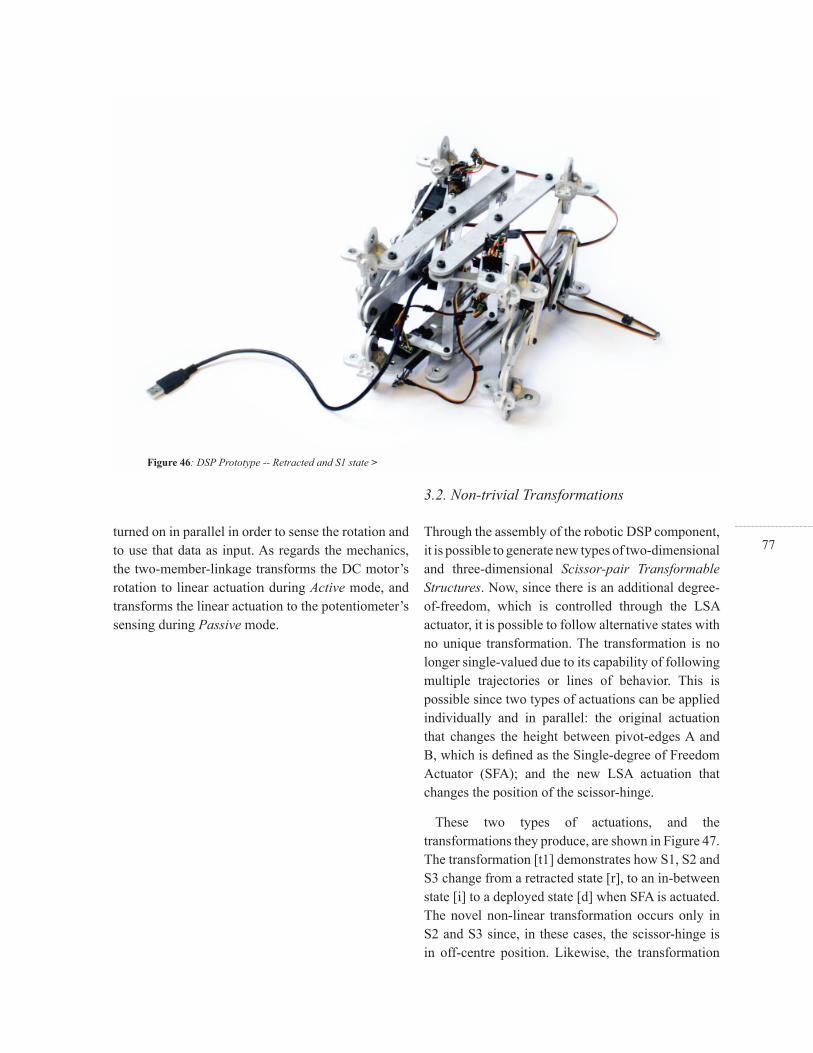
77turned on in parallel in order to sense the rotation and to use that data as input. As regards the mechanics, the two-member-linkage transforms the DC motor’s rotation to linear actuation during Active mode, and transforms the linear actuation to the potentiometer’s sensing during Passive mode.
Through the assembly of the robotic DSP component, it is possible to generate new types of two-dimensional and three-dimensional Scissor-pair Transformable Structures. Now, since there is an additional degree-of-freedom, which is controlled through the LSA actuator, it is possible to follow alternative states with no unique transformation. The transformation is no longer single-valued due to its capability of following multiple trajectories or lines of behavior. This is possible since two types of actuations can be applied individually and in parallel: the original actuation that changes the height between pivot-edges A and B, which is defi ned as the Single-degree of Freedom Actuator (SFA); and the new LSA actuation that changes the position of the scissor-hinge.
These two types of actuations, and the transformations they produce, are shown in Figure 47. The transformation [t1] demonstrates how S1, S2 and S3 change from a retracted state [r], to an in-between state [i] to a deployed state [d] when SFA is actuated. The novel non-linear transformation occurs only in S2 and S3 since, in these cases, the scissor-hinge is in off-centre position. Likewise, the transformation
3.2. Non-trivial Transformations
< Figure 46: DSP Prototype -- Retracted and S1 state
Figure 46: DSP Prototype -- Retracted and S1 state >
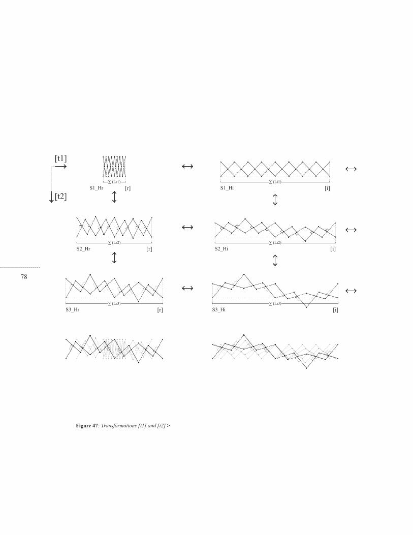
78
Figure 47: Transformations [t1] and [t2] >

79

80[t2] demonstrates how the components change during LSA actuation. Even though this transformation is likewise non-linear, the outcome, or the shape and behavior, is different than in transformation [t1]. An interesting approach is to consider diagonal relations between transformation [t1] and [t2] as well. It is certainly possible to combine both actuations, SFA and LSA, in parallel and in coordination to create additional solutions.
The advantage of transformation [t1] is that control is reduced to one variable, the height between pivot edges A and B. The rotations are propagated and so, in theory, it is only necessary to actuate one scissor-pair to affect the whole structure. Although this transformation is novel and non-linear, offering a range of possible states, the shapes that can be produced within that range are fi xed. The main advantage of transformation [t2] is that control is multiple and can be locally applied to each scissor-hinge in parallel. Thus, it is possible to transform the way the structure transforms, generating different shapes anytime the structure is actuated. Yet, this great advantage implies the use of one actuation per
scissor-pair, and the coordination of their behavior in parallel, which is expensive and diffi cult to resolve. However, it may be possible to combine transformations [t1] and [t2], in order to benefi t from the advantages of each, changing the rules through time with a reasonable number of actuators.
Figures 48 and 49 display ways to combine S1 and S3. This is possible since the height Hd is the same in both. It is important to clarify that the components are still actuated and that this confi guration simply shows one DSP’s state within a range of possible alternatives. Whereas Figure 48 illustrates how transformation [t1] occurs, when LSA actuation is -momentarily- fi xed and SFA actuated, Figure 49 shows how transformation [t2] happens when SFA is fi xed and LSA is actuated. The second case, shown in Figure 49, offers a way to combine the advantages of [t1] and [t2]. The LSA actuation does not have to be applied to the whole structure. Components considered as S3 enable local transformation [t2], and components considered as S1enable single actuation to coordinate the H and L variation.
Figure 48: Transformation [t1] for S1-S3 combination >
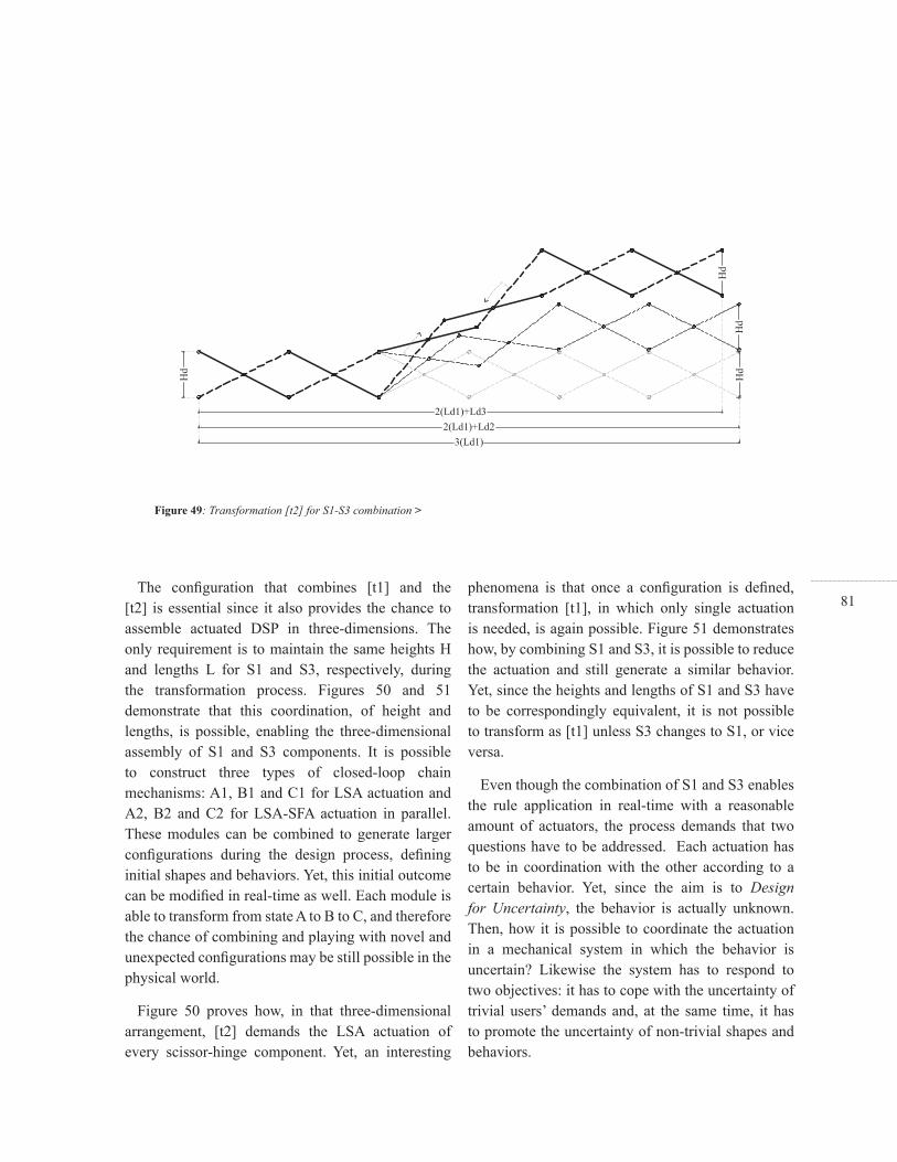
81The confi guration that combines [t1] and the
[t2] is essential since it also provides the chance to assemble actuated DSP in three-dimensions. The only requirement is to maintain the same heights H and lengths L for S1 and S3, respectively, during the transformation process. Figures 50 and 51 demonstrate that this coordination, of height and lengths, is possible, enabling the three-dimensional assembly of S1 and S3 components. It is possible to construct three types of closed-loop chain mechanisms: A1, B1 and C1 for LSA actuation and A2, B2 and C2 for LSA-SFA actuation in parallel. These modules can be combined to generate larger confi gurations during the design process, defi ning initial shapes and behaviors. Yet, this initial outcome can be modifi ed in real-time as well. Each module is able to transform from state A to B to C, and therefore the chance of combining and playing with novel and unexpected confi gurations may be still possible in the physical world.
Figure 50 proves how, in that three-dimensional arrangement, [t2] demands the LSA actuation of every scissor-hinge component. Yet, an interesting
phenomena is that once a confi guration is defi ned, transformation [t1], in which only single actuation is needed, is again possible. Figure 51 demonstrates how, by combining S1 and S3, it is possible to reduce the actuation and still generate a similar behavior. Yet, since the heights and lengths of S1 and S3 have to be correspondingly equivalent, it is not possible to transform as [t1] unless S3 changes to S1, or vice versa.
Even though the combination of S1 and S3 enables the rule application in real-time with a reasonable amount of actuators, the process demands that two questions have to be addressed. Each actuation has to be in coordination with the other according to a certain behavior. Yet, since the aim is to Design for Uncertainty, the behavior is actually unknown. Then, how it is possible to coordinate the actuation in a mechanical system in which the behavior is uncertain? Likewise the system has to respond to two objectives: it has to cope with the uncertainty of trivial users’ demands and, at the same time, it has to promote the uncertainty of non-trivial shapes and behaviors.
Figure 49: Transformation [t2] for S1-S3 combination >

82
Figure 50: LSA actuated modules >
Figure 51: LSA-SFA actuated modules >
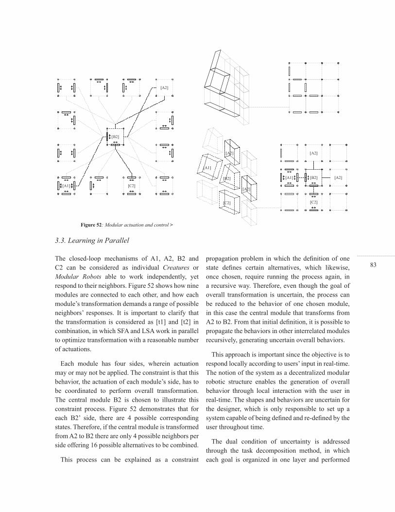
83The closed-loop mechanisms of A1, A2, B2 and C2 can be considered as individual Creatures or Modular Robots able to work independently, yet respond to their neighbors. Figure 52 shows how nine modules are connected to each other, and how each module’s transformation demands a range of possible neighbors’ responses. It is important to clarify that the transformation is considered as [t1] and [t2] in combination, in which SFA and LSA work in parallel to optimize transformation with a reasonable number of actuations.
Each module has four sides, wherein actuation may or may not be applied. The constraint is that this behavior, the actuation of each module’s side, has to be coordinated to perform overall transformation. The central module B2 is chosen to illustrate this constraint process. Figure 52 demonstrates that for each B2’ side, there are 4 possible corresponding states. Therefore, if the central module is transformed from A2 to B2 there are only 4 possible neighbors per side offering 16 possible alternatives to be combined.
This process can be explained as a constraint
propagation problem in which the defi nition of one state defi nes certain alternatives, which likewise, once chosen, require running the process again, in a recursive way. Therefore, even though the goal of overall transformation is uncertain, the process can be reduced to the behavior of one chosen module, in this case the central module that transforms from A2 to B2. From that initial defi nition, it is possible to propagate the behaviors in other interrelated modules recursively, generating uncertain overall behaviors.
This approach is important since the objective is to respond locally according to users’ input in real-time. The notion of the system as a decentralized modular robotic structure enables the generation of overall behavior through local interaction with the user in real-time. The shapes and behaviors are uncertain for the designer, which is only responsible to set up a system capable of being defi ned and re-defi ned by the user throughout time.
The dual condition of uncertainty is addressed through the task decomposition method, in which each goal is organized in one layer and performed
3.3. Learning in Parallel
Figure 52: Modular actuation and control >

84in parallel. In order to Design for Uncertainty, two activities are defi ned for the robotic Scissor-pair Transformable Structure, as noted:
A-Trivial behavior: Responds to users’ expectations, behaving according to the demands in a predictable way. In this case, the user gives some inputs and, after observing the outputs, is able to predict how the structure is going to transform.
B-Non-trivial behavior: Does not respond to users’ expectation, behaving in unpredictable ways in order to promote unexpected outcomes. In this case, the user is not able to understand how the structure works and therefore, for the user, the transformations are always new.
What must be noted is that the fi rst layer, the trivial machine, is the default mode, and that the non-trivial mode only operates when the user is looking and willing to obtain uncertain outcomes. Figure 53 explains the process of activity decomposition in robotic Scissor-Pair Transformable Structures. The diagram shown in Figure 53 is based on constraint
propagation, explained in Figure 52. Each module has to process the loop independently since the system is locally controlled by a microprocessor. There is no central control and the modules operate according to the user’s input, during Passive mode, and according to their neighbors during Active mode.
The process launches as a trivial mode by checking the status of the module. If there is human input, the system is set in passive mode, wherein actuators are turned Off in order to sense the transformation from state [0] to state [1]. Otherwise, the system is set in active mode and through the constraint propagation, explained in Figure 52, the system has to fi nd a proper candidate and actuate accordingly.
In the beginning, the system will choose arbitrarily, and may appear erratic to the user. Yet through practice, the system will learn what types of states are chosen by the user and likewise how to optimize the number of actuations. Nevertheless, this learning process may be overridden every time the user is willing to get uncertain shapes and behaviors. By activating the non-trivial mode, the possible

85candidates are, again, modifi ed arbitrarily. Likewise, since the human input is applied locally, the non-trivial behavior may emerge in other regions of the structure and not necessarily in neighboring modules.
Figure 54 shows that certain behaviors require more actuation than others. The designer may want to optimize a certain number of actuators, allowing the system a certain degree of uncertainty. In this case, fortunately less actuation generates double curvature, which may be aesthetically interesting for the designer and the user. Therefore, the learning algorithm that optimizes the number of actuations may likewise be an aesthetic goal for the designer or user.
The consideration of each closed-loop mechanism as an individual modular robot enables an aditional type of transformation. In Figure 52 is is demostrated how the sides of each module are shared and therefore they follow the same behavior. Yet it is possible to consider certain sides as two DSP components -- one for each corresponding module -- which may behave independently. Figure 54 shows how the vertical
sides of each module can be considered as two DSP components producing an aditional behavior: during transformation the system may allow modular disconection generating structural discontinuity, fi ssures and openings. This new capability may have interesting implications for the architectural application of Scissor-pair Transformable Structures. It may be possible to envision vertical scissor-pair structures able to separate space according to a range of possible and uncertain solutions. Instead of deciding the fi nal shape of a vertical partition and the location of the openings and connections between one side and the other -- where to place the door or window -- it may be possible to defi ne a range of possibilities and different ways to open and close the structure as a whole: a malleable and indeterminate partition that can be opened, closed and changed with need, according to functional and aesthetic criteria controlled and chosen in real-time.
Figure 53: Activity layer decomposition >
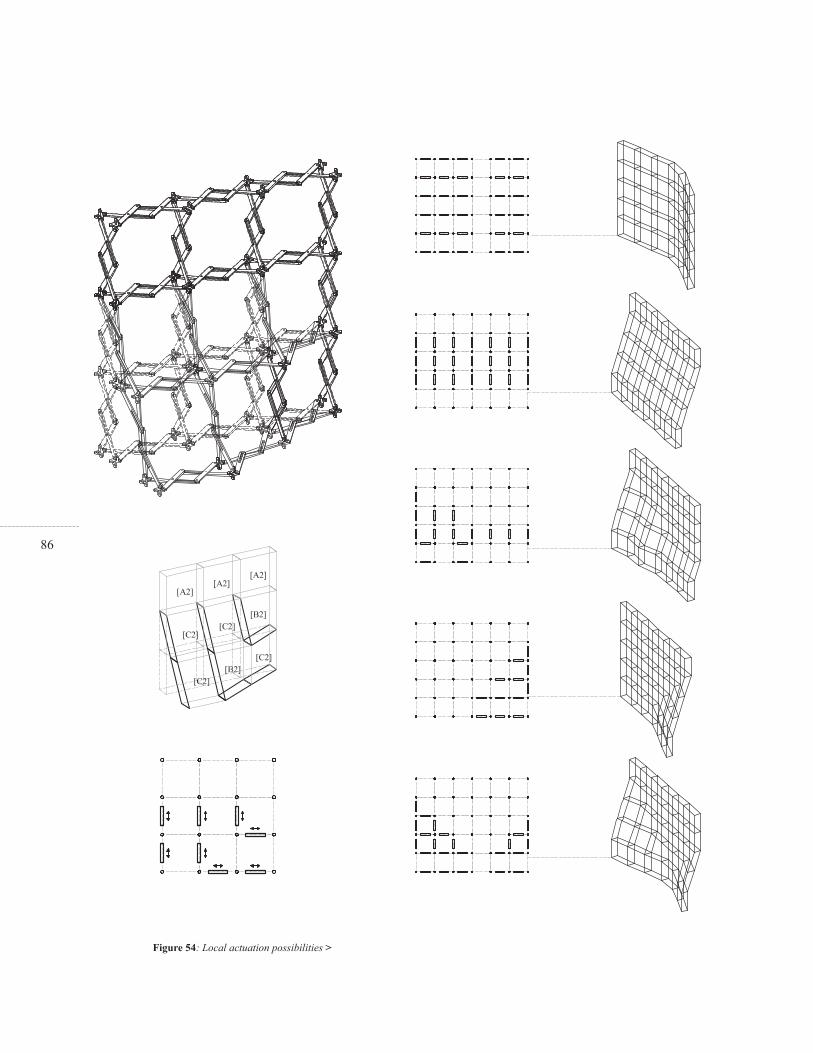
86
Figure 54: Local actuation possibilities >
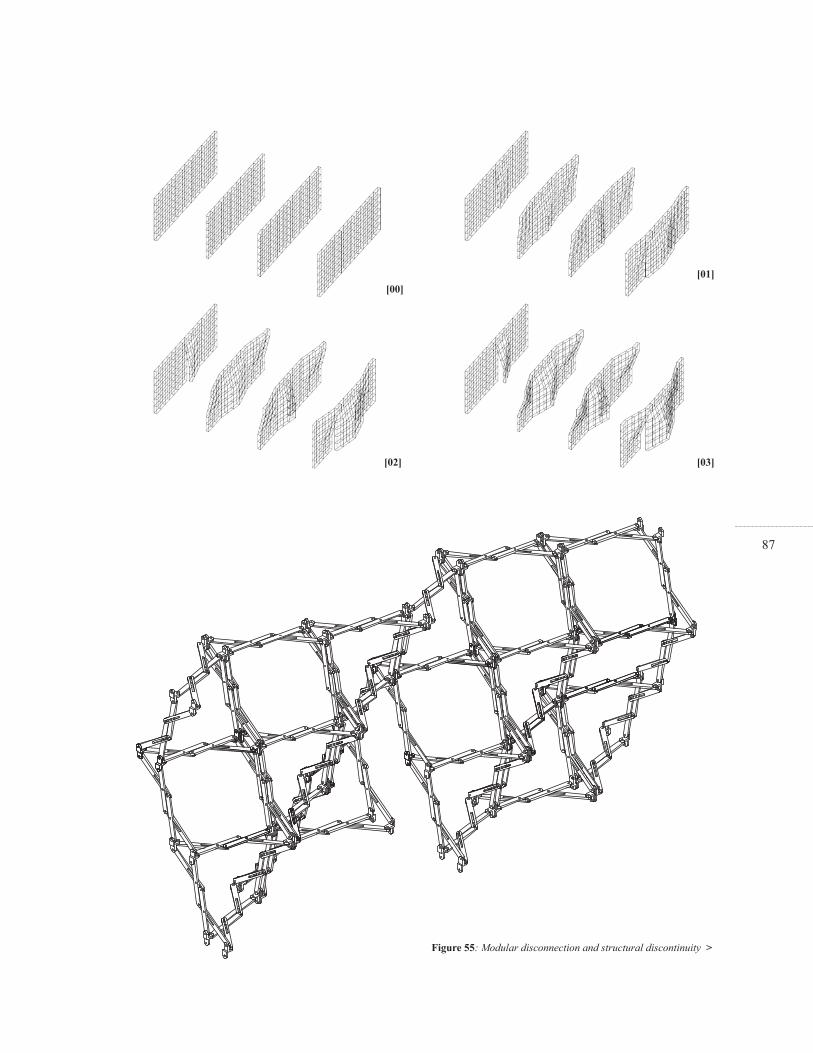
87
Figure 55: Modular disconnection and structural discontinuity >
[02]
[00]
[03]
[01]

88

89
> CONCLUSIONS
The main objective of this thesis was to present a novel method that fosters Designing for Uncertainty and demonstrate an empirical experiment that explores the generation of uncertain shapes and behaviors using Scissor-pair Transformable Structures. The model proposed general directions to be applied across a range of different types of design projects. The fi rst application of these directions was the materialization of uncertainty through experimentation with Scissor-pair Transformable Structures.
The thesis began the discussion of the two types of uncertainties: the uncertainty of the outcome during design conception and the uncertainty of future change during the life of the building. Ideas and projects within design theory and architectural practice were studied with the purpose of fi nding similarities and potential connections. It was found that both processes, the design conception and the life of the building, can be related since both are loops of construction and re-construction that use similar concepts that can enrich one another. This relation was crystallized by constructing a novel model that utilizes both uncertainties to promote a new attitude towards

90Designing for Uncertainty in architectural practice and education. Then, the general directions defi ned in the model were used in a specifi c application involving the conceptual design and physical implementation of Scissor-pair Transformable Structures. Current scissor-pair solutions were studied and modifi ed. The intention was to use the model to study non-linear transformation in the in-between states, with the aim of fi nding novel shapes and thus extending the current repertoire of scissor-pair solutions. A key discovery was the DSP component, which can perform novel shapes and behaviors in the in-between states throughout transformation. In this new type of solution, the slope and dimension of the overall shape are transformed non-linearly, without losing the advantages of control and synchronization during the process. Finally the DSP solution was actuated using sensory-motor control in order to been able to tweak the original confi guration in real-time. It was discovered that local actuation was also possible.
Regarding the contributions of the model, it is possible to say that its novelty resides in the creation of a methodology that relates existing theories and
projects not related before. In other words, the model that fosters Designing for Uncertainty was formed by learning from how uncertainty was addressed in design theory and in architectural practice. The model not only acknowledges the uncertainty of the outcome and the uncertainty of future change, but proposes a fresh relationship between both, which turns into a new comprehensive way to use uncertainty within architectural design. The intention of the model was to propose general directions to be applied to other design situations. The use of scissor-pair structures was chosen as a particular application that complements the model without restricting its application in other types of design projects. In spite of the fact that the model was tested through the design of Scissor-pair Transformable Structures, in order to probe its universality it would have been ideal to have had the time to test the model in other solutions.
In terms of the experiment itself, the fi rst contribution is that of applying the directions of the general model in a particular application, and the second is that of extending the current repertoire of
Figure 56: Transformable Partition >
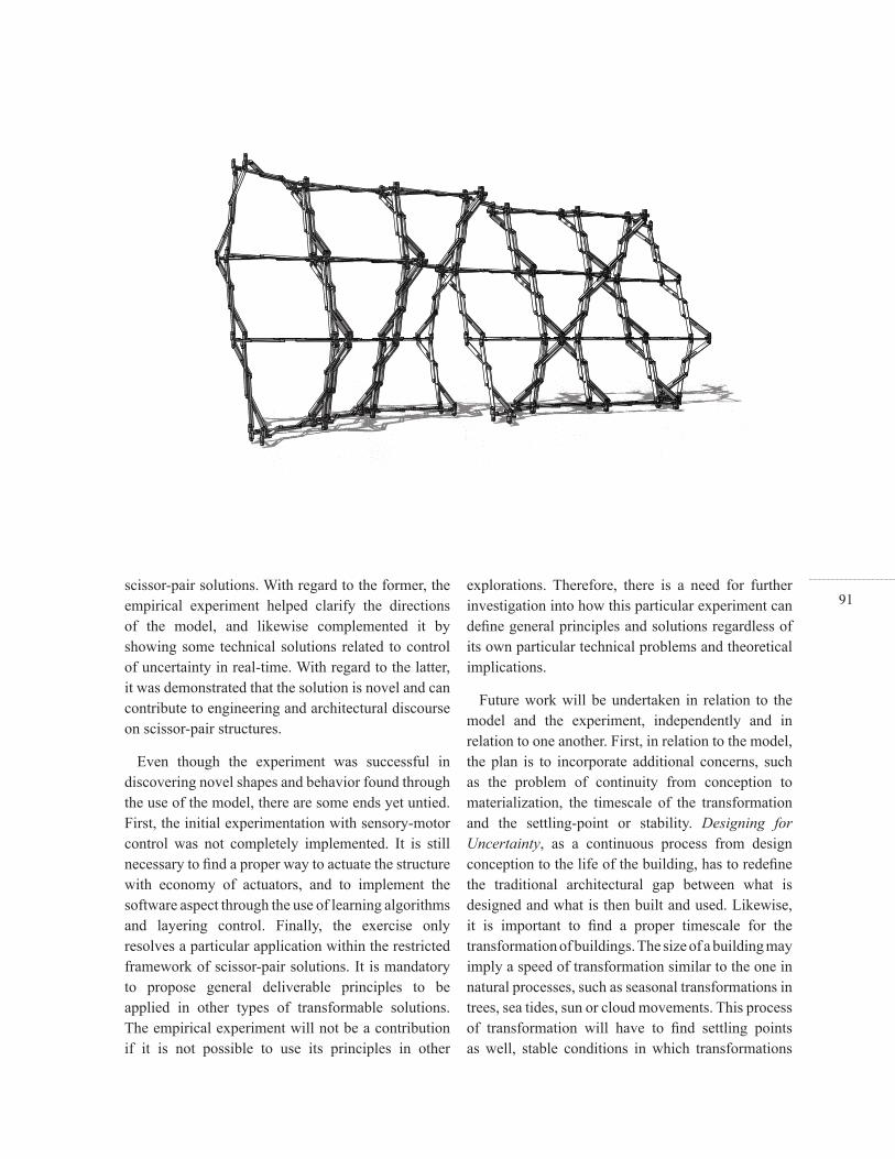
91scissor-pair solutions. With regard to the former, the empirical experiment helped clarify the directions of the model, and likewise complemented it by showing some technical solutions related to control of uncertainty in real-time. With regard to the latter, it was demonstrated that the solution is novel and can contribute to engineering and architectural discourse on scissor-pair structures.
Even though the experiment was successful in discovering novel shapes and behavior found through the use of the model, there are some ends yet untied. First, the initial experimentation with sensory-motor control was not completely implemented. It is still necessary to fi nd a proper way to actuate the structure with economy of actuators, and to implement the software aspect through the use of learning algorithms and layering control. Finally, the exercise only resolves a particular application within the restricted framework of scissor-pair solutions. It is mandatory to propose general deliverable principles to be applied in other types of transformable solutions. The empirical experiment will not be a contribution if it is not possible to use its principles in other
explorations. Therefore, there is a need for further investigation into how this particular experiment can defi ne general principles and solutions regardless of its own particular technical problems and theoretical implications.
Future work will be undertaken in relation to the model and the experiment, independently and in relation to one another. First, in relation to the model, the plan is to incorporate additional concerns, such as the problem of continuity from conception to materialization, the timescale of the transformation and the settling-point or stability. Designing for Uncertainty, as a continuous process from design conception to the life of the building, has to redefi ne the traditional architectural gap between what is designed and what is then built and used. Likewise, it is important to fi nd a proper timescale for the transformation of buildings. The size of a building may imply a speed of transformation similar to the one in natural processes, such as seasonal transformations in trees, sea tides, sun or cloud movements. This process of transformation will have to fi nd settling points as well, stable conditions in which transformations

92would not be required anymore, at least momentarily. Second, in relation to the experiment, the plan is to fi nd potential architectural applications and to use some of the experiment’s principles in other types of transformable structures. The DSP solution offers a range of possible shapes and behaviors that can be applied to different architectural applications, such as partitions, walls, roofs and enclosures in general (Figure 56). The belief is that by restricting its functionality, it will be possible to complete the design of the actual solution. Likewise, some of the experiment’s principles, such as the transformation of the transformation, learning by recording cases, layering control and non-trivial behaviors, may foster other types of solutions, not necessarily Scissor-pair Transformable Structures.
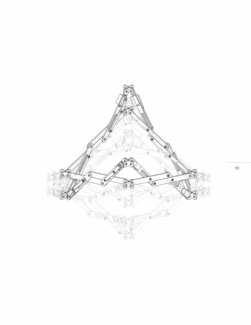
93

94Aboaf, Eric. Task-level robot learning. Cambridge, Massachusetts: M.S Thesis, Department of Electrical Engineering and Computer Science, MIT, 1988.
Aboaf, Eric, Steven Drucker, and Christopher Atkeson. “Task-level robot learning: Juggling a Tennis Ball More Accurately.” IEEE, 1989: 1290-1295.
Alexander, Christopher. Notes on the synthesis of form. Cambridge, Massachusetts: Harvard University Press, 1964.
Andeen, Gerry. Robot design handbook. New York: R.R Donnelley & Sons, 1988.
Archer, Bruce. The Structure of Design Processes. London: Royal College of Art, 1968.
Ashby, Rosh. An introduction to cybernetics. London: Methuen & Co, 1976.
Brooks, Rodney. “Intelligence without representation.” Artifi cial Intelligence, 1991: 139-159.
Buhl, Thomas, Jensen, Frank and Pellegrino Sergio. “Shape optimization of cover plates retractable roof structures.” Computers and Structures, 2004: 1227-1236.
Cook, Peter. Archigram. New York: Princeton Architectural Press, 1999.
Dewey, John. Logic: the theory of inquiry. New York: Holt and Company, 1938.
Edwards, George. Expanding apparatus for fi re escapes. US Patent 415,667, 1889.
Escrig, F. “Expandable space structure.” Internation Journal of Space Structures, 1985: 79-91.
Escrig, F, and J.P Valcarcel. “Geometry of expandable space structures.” International Journal of Space Structures, 1985: 79-91.
Foerster, Heinz Von. “On constructing a reality.” Observing systems, 1981: 295.
Hoberman, Charles. Radial expansion/retraction truss structures. US patent no. 4942700, 1990.
Hughes, Jonathan. “The indeterminate building.” In Non-Plan: essays on fredom participation and change in modern architecture and urbanism, by Jonathan Hughes and Simon Sadler, 90-103. Boston, Massachusetts: Architectural Press, 2000.
Kronenburg, Robert. Flexible: Architecture that Responds to Change. fsf: Laurence King Publishers, 2007.
Lester, Richard, and Michael Piore. Innovation the missing dimension. Cambridge, Massachusetts: Harvard
> References
95University Press, 2004.
Luckey, George. Nesting three dimensional lazy tong structure. US Patent no 3,672,104, 1972.
Murata, Satoshi, and Haruhisa Kurokawa. “Self-Reconfi gurable Robots.” IEEE Robotics & Automation, 2007: 71-78.
Pinero, Emilio. Spain Patent no. 266801, 1961.
Price, Cedric. “Anticipating the Unexpected: Cedric Price special issue.” The Architects’ Journal, 1996.
—. The square book. Chichester: Wiley Academy, 2003.
Raffl e, Hayes Solos. Topobo: A 3D Constructive Assembly System with Kinetic Memory. Cambridge, Massachusetts: M.S Thesis, Media Arts and Sciences, MIT, 2004.
Sadler, Simon. Archigram Architecture without Architecture. Cambridge, Massachusetts: MIT Press, 2005.
Schön, Donald. Educating the Refl ective Practitioner. San Francisco, California. : Jossey-Bass, 1987.
Segal, Lynn. The dream of reality Heinz von Foerster’s Constructivism. New York: Springer-Verlag, 2001.
Simon, Herbert. A. The Science of the Artifi cial.
Cambridge, Massachusetts: MIT Press, 1996.
Stiny, George. Shape Talking about Seeing and Doing. Cambridge, Massachusetts: MIT Press, 2006.
Vepa, Ranjan. Biomimetic robotics mechanisms and control. New York: Cambridge University Press, 2009.
Weiner, Norbert. Cybernetics. New York: John Wiley & Sons, 1948.
Winston, Patrick. Artifi cial Intelligence. Cambridge, Massachusetts: Addison-Wesley, 1992.
Yim, M, et al. “Modular Self-Reconfi gurable Robot Systems.” IEEE Robotics & Automation, 2007: 43-52.
You, Zhong, and Pellegrino, Sergio. “Foldable bar structures.” International Journal of solids and Structures, 1996: 1825-1847.
Zeigler, Theodore. Collapsible Self-Supporting Structure, US patent no. 3968808, 1974.
Zuk, William, and Roger Clark. Kinetic Architecture. New York: Van Nostrand Reinhold, 1970.
Zykov, Victor. Morphological and Behavioral Resilience against Physical Damage for Robotic Systems. Ithaca, NY: PhD Thesis, Department of Mechanical Engineering, Cornell University, 2008.

96Figure 01: Alexander, Christopher. Notes on the synthesis of form. Cambridge, Massachusetts: Harvard University Press, 1964, pp 62.
Figure 03: Stiny, George. Shape Talking about Seeing and Doing. Cambridge, Massachusetts: MIT Press, 2006, Front page.
Figure 04: Sadler, Simon. Archigram Architecture without Architecture. Cambridge, Massachusetts: MIT Press, 2005, pp 89.
Figure 05: Stiny, George. Shape Talking about Seeing and Doing. Cambridge, Massachusetts: MIT Press, 2006, pp 106.
Figure 08: Stiny, George. Shape Talking about Seeing and Doing. Cambridge, Massachusetts: MIT Press, 2006, pp 336.
Figure 09: Hughes, Jonathan. “The indeterminate building.” In Non-Plan: essays on fredom participation and change in modern architecture and urbanism, by Jonathan Hughes and Simon Sadler, 90-103. Boston, Massachusetts: Architectural Press, 2000, pp 91.
Figure 10: Cook, Peter. Archigram. New York: Princeton Architectural Press, 1999, pp 69.
Figure 11: Cook, Peter. Archigram. New York:
Princeton Architectural Press, 1999, pp 69.
Figure 12: Lost Masterpieces. London: Phaidon Press Limited, 1999, pp 73.
Figure 13: Zuk, William, and Roger Clark. Kinetic Architecture. New York: Van Nostrand Reinhold, 1970, pp 98.
Figure 14: Zuk, William, and Roger Clark. Kinetic Architecture. New York: Van Nostrand Reinhold, 1970, pp 21.
Figure 15: Price, Cedric. The square book. Chichester: Wiley Academy, 2003, pp 63.
Figure 16: Price, Cedric. The square book. Chichester: Wiley Academy, 2003, pp 58.
Figure 17: Cook, Peter. Archigram. New York: Princeton Architectural Press, 1999, pp 71.
Figure 20: Segal, Lynn. The dream of reality Heinz von Foerster’s Constructivism. New York: Springer-Verlag, 2001, pp 89.
Figure 24: Escrig, F, and J.P Valcarcel. “Geometry of expandable space structures.” International Journal of Space Structures, 1985, pp 86.
Figure 25: Hoberman, Charles. Radial expansion/
> Figure References

97retraction truss structures. US patent no. 4942700, 1990.
Figure 38: Reuleaux, Franz. The kinematics of machinery. New York: Dover Publications, 1963, pp 49.
Figure 39: Lenarcic, Jadran, and Vicenzo Parenti-Castelli. Recent Advances in robot Kinematics. Dordrecht: Kluwer Academic Publishers, 1996, pp 8.
Figure 40: Brooks, Rodney. “Intelligence without representation.” Artifi cial Intelligence, 1991, pp 152.
Figure 41: Atkeson, Christopher. “Learning tasks from single demostration.” IEEE International Conference on robotics and Automation, 1997, pp 1707.
Figure 42: Zykov, Victor. Morphological and Behavioral Resilience against Physical Damage for Robotic Systems. Ithaca, NY: PhD Thesis, Department of Mechanical Engineering, Cornell University, 2008, pp 200.
Figure 43: Raffl e, Hayes Solos. Topobo: A 3D Constructive Assembly System with Kinetic Memory. Cambridge, Massachusetts: M.S Thesis, Media Arts and Sciences, MIT, 2004, pp 48.

98

99
Related Documents