UNCORRECTED PROOF SCICO: 974 + Model pp. 1–16 (col. fig: NIL) ARTICLE IN PRESS Science of Computer Programming xx (xxxx) xxx–xxx www.elsevier.com/locate/scico Designing and managing evolving systems using a MAS product line approach ✩ Joaquin Pe ˜ na a,* , Michael G. Hinchey b , Manuel Resinas a , Roy Sterritt c , James L. Rash b a University of Seville, Spain b NASA Goddard Space Flight Center, MD, USA c University of Ulster, United Kingdom Received 2 April 2006; received in revised form 6 September 2006; accepted 13 October 2006 1 2 Abstract 3 We view an evolutionary system as being a software product line. The core architecture is the unchanging part of the system, 4 and each version of the system may be viewed as a product from the product line. Each “product” may be described as the core 5 architecture with some agent-based additions. The result is a multiagent system software product line. We describe an approach to 6 such a software product line-based approach using the MaCMAS agent-oriented methodology. The approach scales to enterprise 7 architectures as a multiagent system is an appropriate means of representing a changing enterprise architecture and the interaction 8 between components in it. In addition, we reduce the gap between the enterprise architecture and the software architecture. 9 c 2007 Published by Elsevier B.V. 10 Keywords: Multiagent systems product lines; Enterprise architecture evolution; Swarm-based systems 11 1. Introduction 12 When dealing with complex systems, and in particular systems exhibiting any form of autonomy or autonomic 13 properties, it is unrealistic to assume that the system will be static. Complex systems evolve over time, and the 14 architecture of an evolving system will change even at run time, as the system implements self-configuration, self- 15 adaptation, and meets the challenges of its environment. 16 An evolving system can be viewed as multiple versions of the same system. That is, as the system evolves it 17 essentially represents multiple instances of the same system, each with its own variations and specific changes. That 18 is to say, an evolving system may be viewed as a product line of systems, where the core architecture of the product 19 line is fixed (i.e., the substantial part of the system that does not change), and each version of the evolving system may 20 be viewed as a particular product from the product line. 21 ✩ The work reported in this article was supported by the Spanish Ministry of Science and Technology under grants TIC2003-02737-C02-01 and TIN2006-00472, by the NASA Software Engineering Laboratory, NASA Goddard Space Flight Center, Greenbelt, MD, USA. * Corresponding author. E-mail addresses: [email protected] (J. Pe ˜ na), [email protected] (M.G. Hinchey), [email protected] (M. Resinas), [email protected] (R. Sterritt), [email protected] (J.L. Rash). 0167-6423/$ - see front matter c 2007 Published by Elsevier B.V. doi:10.1016/j.scico.2006.10.007 Please cite this article in press as: J. Pe˜ na, et al., Designing and managing evolving systems using a MAS product line approach, Science of Computer Programming (2007), doi:10.1016/j.scico.2006.10.007

Welcome message from author
This document is posted to help you gain knowledge. Please leave a comment to let me know what you think about it! Share it to your friends and learn new things together.
Transcript
UN
CO
RR
ECTE
DPR
OO
F
SCICO: 974 + Model pp. 1–16 (col. fig: NIL)
ARTICLE IN PRESS
Science of Computer Programming xx (xxxx) xxx–xxxwww.elsevier.com/locate/scico
Designing and managing evolving systems using a MAS productline approachI
Joaquin Penaa,∗, Michael G. Hincheyb, Manuel Resinasa, Roy Sterrittc, James L. Rashb
a University of Seville, Spainb NASA Goddard Space Flight Center, MD, USA
c University of Ulster, United Kingdom
Received 2 April 2006; received in revised form 6 September 2006; accepted 13 October 2006
12
Abstract 3
We view an evolutionary system as being a software product line. The core architecture is the unchanging part of the system, 4
and each version of the system may be viewed as a product from the product line. Each “product” may be described as the core 5
architecture with some agent-based additions. The result is a multiagent system software product line. We describe an approach to 6
such a software product line-based approach using the MaCMAS agent-oriented methodology. The approach scales to enterprise 7
architectures as a multiagent system is an appropriate means of representing a changing enterprise architecture and the interaction 8
between components in it. In addition, we reduce the gap between the enterprise architecture and the software architecture. 9
c© 2007 Published by Elsevier B.V. 10
Keywords: Multiagent systems product lines; Enterprise architecture evolution; Swarm-based systems11
1. Introduction 12
When dealing with complex systems, and in particular systems exhibiting any form of autonomy or autonomic 13
properties, it is unrealistic to assume that the system will be static. Complex systems evolve over time, and the 14
architecture of an evolving system will change even at run time, as the system implements self-configuration, self- 15
adaptation, and meets the challenges of its environment. 16
An evolving system can be viewed as multiple versions of the same system. That is, as the system evolves it 17
essentially represents multiple instances of the same system, each with its own variations and specific changes. That 18
is to say, an evolving system may be viewed as a product line of systems, where the core architecture of the product 19
line is fixed (i.e., the substantial part of the system that does not change), and each version of the evolving system may 20
be viewed as a particular product from the product line. 21
I The work reported in this article was supported by the Spanish Ministry of Science and Technology under grants TIC2003-02737-C02-01 andTIN2006-00472, by the NASA Software Engineering Laboratory, NASA Goddard Space Flight Center, Greenbelt, MD, USA.
∗ Corresponding author.E-mail addresses: [email protected] (J. Pena), [email protected] (M.G. Hinchey), [email protected] (M. Resinas),
[email protected] (R. Sterritt), [email protected] (J.L. Rash).
0167-6423/$ - see front matter c© 2007 Published by Elsevier B.V.doi:10.1016/j.scico.2006.10.007
Please cite this article in press as: J. Pena, et al., Designing and managing evolving systems using a MAS product line approach, Science ofComputer Programming (2007), doi:10.1016/j.scico.2006.10.007

UN
CO
RR
ECTE
DPR
OO
F
SCICO: 974
ARTICLE IN PRESS2 J. Pena et al. / Science of Computer Programming xx (xxxx) xxx–xxx
Similarly, an enterprise architecture may be viewed as the core architecture that is unchanging, and various1
specializations of the architecture (as the enterprise evolves) implement various products of the product line.2
In this paper, we use multiagent-based modelling techniques to model software systems that evolve over time. The3
result is that an evolving system can be viewed as a software product line of MultiAgent Systems (MAS). Therefore, if4
we consider the unchanging part of a software system or of an enterprise to be the core architecture, the specialization5
to various products (versions of the system) can be viewed as agent-based additions.6
Our approach scales to enterprise architectures and software architecture for two reasons. Firstly, a multiagent7
system is a very appropriate means of representing an enterprise and the interactions within it, thanks to the8
organizational metaphor that architects the system mimicking the real enterprise organization. Secondly, the gap9
between the enterprise architecture and the software architecture is mitigated through the addition of architectural10
concepts at the running platform. That is to say, MAS platforms are able to manage architectural evolutions and11
support architectural concepts at the implementation level.12
In this paper, we propose a set of software engineering techniques based on an agent-oriented methodology13
called Methodology for analyzing Complex MultiAgent Systems (MaCMAS) that is designed to deal with complex14
unpredictable systems [11].1 Specifically, the approach we use is based on an extension of MaCMAS that allows15
one to model MAS Product Lines (MASPL) [14,13]. This allows us to manage the modeling of the evolution of the16
system in a systematic way.17
The main contributions of this paper are: (i) to the best of our knowledge, this is the first approach that deals18
with architectural changes of evolving systems based on MAS-PL; (ii) we reduce the gap between the enterprise and19
software architecture.20
2. Motivating our approach with two case studies: A NASA case study and a human organization case study21
The NASA case study focuses on showing a complex evolving system and is used to show how this is managed in22
our approach. The second case study focuses on showing the gap between the enterprise architecture and the software23
architecture and how it is managed in our approach.24
2.1. A NASA case study25
There has been significant NASA research on the subject of agent technology, with a view to greater exploitation26
of such technologies in future missions.27
The ANTS (Autonomous Nano-Technology Swarm) concept mission, for example, will be based on a grouping of28
agents that work jointly and autonomously to achieve mission goals, analogous to a swarm in nature.29
The Prospecting Asteroid Mission (PAM) is a concept sub-mission based on the ANTS concepts that will be30
dedicated to exploring the asteroid belt. A thousand picospacecraft (less than 1 kg each) may be launched from a point31
in space forming sub-swarms, and deployed to study asteroids of interest in the asteroid belt.32
The software architecture of this system changes at run time depending on the environment and the state of the33
swarm. To simplify our examples, from all the possible evolutions we show only two states of the system: in the first34
one, the swarm is orbiting an asteroid in order to analyze it; in the second, a solar storm occurs in the environment35
and the system changes its state to protect itself.36
To orbit and analyze an asteroid the spacecraft in the swarm must calculate and adjust the orbit, perform the37
measures, report the information retrieved, and escape the orbit when the process is finished.38
For protection from a solar storm the spacecraft must take two basic steps: (a) orient its solar sails to minimize39
the area exposed to the solar storm particles (trim sails) and (b) power off all possible electronic components. Step40
(a) minimizes the forces from impinging solar storm particles, which could affect the spacecraft’s orbit. Both steps41
(a) and (b) minimize potential damage from the charged particles in the storm (which can degrade sensors, detectors,42
electronic circuits, and solar energy collectors).43
As shown, the two situations are quite different requiring completely different architecture in the system. This44
motivated us to observe these states as different systems, and thus, led us to the product line field.45
1 See james.eii.us.es/MaCMAS/ for details and case studies using this methodology.
Please cite this article in press as: J. Pena, et al., Designing and managing evolving systems using a MAS product line approach, Science ofComputer Programming (2007), doi:10.1016/j.scico.2006.10.007
UN
CO
RR
ECTE
DPR
OO
F
SCICO: 974
ARTICLE IN PRESSJ. Pena et al. / Science of Computer Programming xx (xxxx) xxx–xxx 3
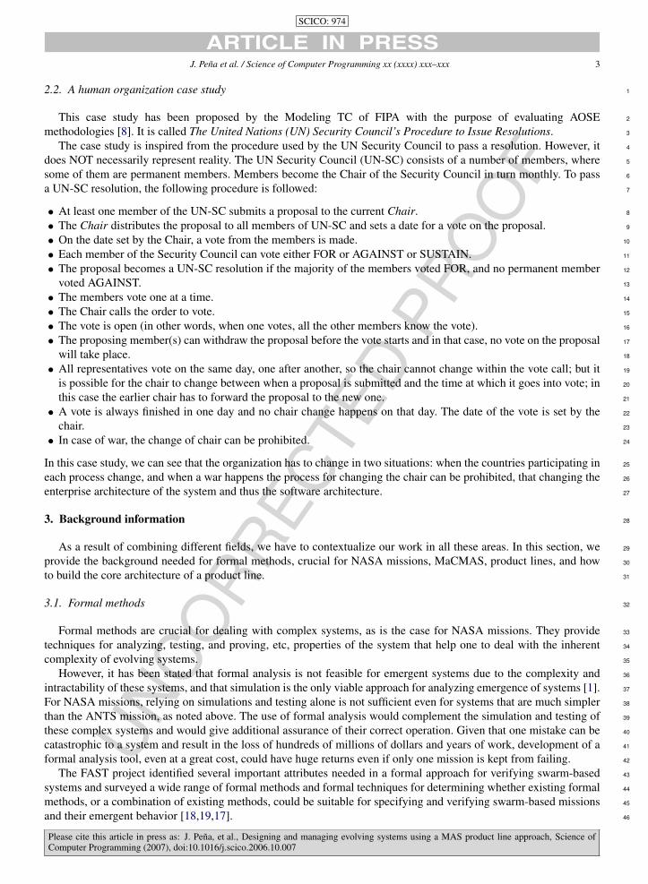
2.2. A human organization case study 1
This case study has been proposed by the Modeling TC of FIPA with the purpose of evaluating AOSE 2
methodologies [8]. It is called The United Nations (UN) Security Council’s Procedure to Issue Resolutions. 3
The case study is inspired from the procedure used by the UN Security Council to pass a resolution. However, it 4
does NOT necessarily represent reality. The UN Security Council (UN-SC) consists of a number of members, where 5
some of them are permanent members. Members become the Chair of the Security Council in turn monthly. To pass 6
a UN-SC resolution, the following procedure is followed: 7
• At least one member of the UN-SC submits a proposal to the current Chair. 8
• The Chair distributes the proposal to all members of UN-SC and sets a date for a vote on the proposal. 9
• On the date set by the Chair, a vote from the members is made. 10
• Each member of the Security Council can vote either FOR or AGAINST or SUSTAIN. 11
• The proposal becomes a UN-SC resolution if the majority of the members voted FOR, and no permanent member 12
voted AGAINST. 13
• The members vote one at a time. 14
• The Chair calls the order to vote. 15
• The vote is open (in other words, when one votes, all the other members know the vote). 16
• The proposing member(s) can withdraw the proposal before the vote starts and in that case, no vote on the proposal 17
will take place. 18
• All representatives vote on the same day, one after another, so the chair cannot change within the vote call; but it 19
is possible for the chair to change between when a proposal is submitted and the time at which it goes into vote; in 20
this case the earlier chair has to forward the proposal to the new one. 21
• A vote is always finished in one day and no chair change happens on that day. The date of the vote is set by the 22
chair. 23
• In case of war, the change of chair can be prohibited. 24
In this case study, we can see that the organization has to change in two situations: when the countries participating in 25
each process change, and when a war happens the process for changing the chair can be prohibited, that changing the 26
enterprise architecture of the system and thus the software architecture. 27
3. Background information 28
As a result of combining different fields, we have to contextualize our work in all these areas. In this section, we 29
provide the background needed for formal methods, crucial for NASA missions, MaCMAS, product lines, and how 30
to build the core architecture of a product line. 31
3.1. Formal methods 32
Formal methods are crucial for dealing with complex systems, as is the case for NASA missions. They provide 33
techniques for analyzing, testing, and proving, etc, properties of the system that help one to deal with the inherent 34
complexity of evolving systems. 35
However, it has been stated that formal analysis is not feasible for emergent systems due to the complexity and 36
intractability of these systems, and that simulation is the only viable approach for analyzing emergence of systems [1]. 37
For NASA missions, relying on simulations and testing alone is not sufficient even for systems that are much simpler 38
than the ANTS mission, as noted above. The use of formal analysis would complement the simulation and testing of 39
these complex systems and would give additional assurance of their correct operation. Given that one mistake can be 40
catastrophic to a system and result in the loss of hundreds of millions of dollars and years of work, development of a 41
formal analysis tool, even at a great cost, could have huge returns even if only one mission is kept from failing. 42
The FAST project identified several important attributes needed in a formal approach for verifying swarm-based 43
systems and surveyed a wide range of formal methods and formal techniques for determining whether existing formal 44
methods, or a combination of existing methods, could be suitable for specifying and verifying swarm-based missions 45
and their emergent behavior [18,19,17]. 46
Please cite this article in press as: J. Pena, et al., Designing and managing evolving systems using a MAS product line approach, Science ofComputer Programming (2007), doi:10.1016/j.scico.2006.10.007

UN
CO
RR
ECTE
DPR
OO
F
SCICO: 974
ARTICLE IN PRESS4 J. Pena et al. / Science of Computer Programming xx (xxxx) xxx–xxx
Fig. 1. Self-protection from solar storms autonomic property model.
One of the main drawbacks found in the application of formal methods relates to the size and scope of the1
specifications. When dealing with complex evolving systems, such as NASA missions based on ANTS, these2
specifications become unmanageable, needing mechanisms to divide and conquer them. The approach presented in this3
paper allows us to factorize the systems, easing the decomposition of the specifications and thus their comprehension.4
3.2. Overview of MaCMAS models5
MaCMAS is the AOSE methodology that we use for our approach. We use this methodology since it is the only6
one that provides explicit support for MAS-PLs. For the purposes of this paper, we only need to know a few features7
of MaCMAS, mainly some of the models it uses. Although a process for building these models is also needed, we do8
not address this in this paper, and refer the interested reader to the literature on this methodology. From the models it9
provides, we are interested in the following:10
(a) Static acquaintance organization view: This shows the static interaction relationships between roles, parts of11
the agent involved in an interaction, in the systems and the knowledge processed by them. In this category, we12
can find models for representing the ontology managed by agents, models for representing their dependencies,13
and role models. For the purposes of this paper we only need to detail role models:14
Role models: show an acquaintance sub-organization as a set of roles collaborating by means of several multi-15
Role Interactions (mRIs). mRIs are used to abstract the acquaintance relationships amongst roles in the system.16
As mRIs allow abstract representation of interactions, we can use these models at whatever level of abstraction17
we desire.18
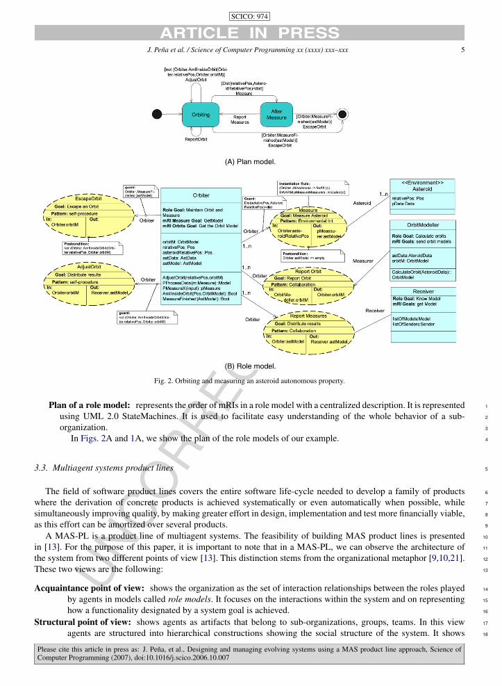
In Figs. 2B and 1B, we show the role model that represents how a swarm spacecraft orbits an asteroid19
and the one representing the protection from a solar storm while the swarm spacecraft continues in its orbit.20
In the figures, interfaces, represented as boxes, represent the static features of roles showing their goals, the21
knowledge managed, and the services provided. mRIs, represented as dashed ellipses, represent the interactions22
between the roles linked to them, showing their goal when collaborating, their pattern of collaboration, and the23
knowledge consumed, used, and obtained from the collaboration.24
(b) Behavior of acquaintance organization view: The behavioral aspect of an organization shows the sequencing of25
mRIs in a particular role model. It is represented by two equivalent models:26
Plan of a role: separately represents the plan of each role in a role model showing how the mRIs of the role27
sequence. It is represented using UML 2.0 ProtocolStateMachines. It is used to focus on a certain role, while28
ignoring others.29
Please cite this article in press as: J. Pena, et al., Designing and managing evolving systems using a MAS product line approach, Science ofComputer Programming (2007), doi:10.1016/j.scico.2006.10.007
UN
CO
RR
ECTE
DPR
OO
F
SCICO: 974
ARTICLE IN PRESSJ. Pena et al. / Science of Computer Programming xx (xxxx) xxx–xxx 5
Fig. 2. Orbiting and measuring an asteroid autonomous property.
Plan of a role model: represents the order of mRIs in a role model with a centralized description. It is represented 1
using UML 2.0 StateMachines. It is used to facilitate easy understanding of the whole behavior of a sub- 2
organization. 3
In Figs. 2A and 1A, we show the plan of the role models of our example. 4
3.3. Multiagent systems product lines 5
The field of software product lines covers the entire software life-cycle needed to develop a family of products 6
where the derivation of concrete products is achieved systematically or even automatically when possible, while 7
simultaneously improving quality, by making greater effort in design, implementation and test more financially viable, 8
as this effort can be amortized over several products. 9
A MAS-PL is a product line of multiagent systems. The feasibility of building MAS product lines is presented 10
in [13]. For the purpose of this paper, it is important to note that in a MAS-PL, we can observe the architecture of 11
the system from two different points of view [13]. This distinction stems from the organizational metaphor [9,10,21]. 12
These two views are the following: 13
Acquaintance point of view: shows the organization as the set of interaction relationships between the roles played 14
by agents in models called role models. It focuses on the interactions within the system and on representing 15
how a functionality designated by a system goal is achieved. 16
Structural point of view: shows agents as artifacts that belong to sub-organizations, groups, teams. In this view 17
agents are structured into hierarchical constructions showing the social structure of the system. It shows 18
Please cite this article in press as: J. Pena, et al., Designing and managing evolving systems using a MAS product line approach, Science ofComputer Programming (2007), doi:10.1016/j.scico.2006.10.007

UN
CO
RR
ECTE
DPR
OO
F
SCICO: 974
ARTICLE IN PRESS6 J. Pena et al. / Science of Computer Programming xx (xxxx) xxx–xxx
Fig. 3. Measure storms model.
which agents are playing the roles in the acquaintance organization, and thus, shows how system goals are1
achieved by means of agents interacting to fulfill the system goals.2
As shown in [6], the acquaintance organization can be modeled orthogonally to its structural organization. This allows3
us to change the system goals that are enabled in the system by changing the parts of the acquaintance organization4
present in the structural organization. This, in fact, is the basis of MAS-PLs.5
The MAS-PL software process is divided into two main stages: domain engineering and application engineering.6
The former is responsible for providing the reusable core assets that are exploited during application engineering7
when assembling or customizing individual applications [15]. Although there are other activities, such as product8
management, in this section we do not try to be exhaustive, but only discuss those activities directly related to this9
paper and relevant to our approach.10
Thus, following the nomenclature used in [15], the activities, usually performed iteratively and in parallel, of11
domain engineering are:12
Domain requirements engineering: This phase describes the requirements of the complete family of products,13
highlighting both the common and the variable features across the family. In this phase, commonality analysis14
is of great importance for aiding in determining which are the commonalities and variabilities. The models15
used in this phase for specifying features show when a feature is optional, mandatory or alternative in the16
family. The models used are called feature models [2,13]. A feature is a characteristic of the system that17
is observable by the end user, which in essence represents the same concept as a system goal, as shown18
previously [5].19
Domain design: This phase produces architecture-independent models, i.e. acquaintance organization models, that20
define the features of the family and the domain of application. MASPLs use role models to represent21
the interfaces and interactions needed to cover certain functionality independently (a feature or a set of22
features) [14]. The most representative references in the non-MASPL field are [4,20]. Similar approaches23
have appeared also in the OO field, for example [3,16], but all of these approaches use role models with the24
same purpose, namely, representing features of the system in isolation from the final enterprise architecture.25
Domain realization: In this phase, a core architecture of the family is produced, and is termed the core structural26
organization of the system. The core architecture is formed as a composition of the role models corresponding27
to the more stable features in the system [13].28
Next, we briefly describe an approach, presented in [14], for building the core architecture of a MASPL, which is29
an important part of the domain engineering stage. The remainder of the article builds on the results of that paper and30
provides techniques that are used during the application engineering stage.31
Please cite this article in press as: J. Pena, et al., Designing and managing evolving systems using a MAS product line approach, Science ofComputer Programming (2007), doi:10.1016/j.scico.2006.10.007

UN
CO
RR
ECTE
DPR
OO
F
SCICO: 974
ARTICLE IN PRESSJ. Pena et al. / Science of Computer Programming xx (xxxx) xxx–xxx 7
Fig. 4. Overview of building the core architecture of a MAS-PL.
3.4. Building the core architecture of a MAS-PL 1
In [14], we presented an approach to building the core architecture of a MAS-PL at the domain engineering stage. 2
In Fig. 4, we show roughly the process we follow to build the core architecture, whose activities are roughly: 3
Build acquaintance organization. The first stage to be performed consists of developing a set of models in different 4
layers of abstraction where we obtain a traceability model and a set of role models showing how each goal is 5
materialized. This is achieved by applying the MaCMAS software process. 6
Build features model. The second activity shown is responsible for adding commonalities and variabilities to the 7
traceability model. This is done modifying the traceability diagram to add information on variability and 8
commonalities to obtain a feature model of the family. It relies on taking each node of the traceability 9
diagram and determining whether it is mandatory, optional, alternative, or-exclusive, or whether it depends 10
on other(s), as shown in the figure. In Fig. 6, we present the resultant features model for the NASA case 11
study. 12
In addition, there exists a direct traceability between features and role models. 13
When a system goal is complex enough to require more than one agent in order to be fulfilled, a group of 14
agents are required to work together. Hence, a role model shows a set of agents, represented by the role they 15
play, that join to achieve a certain system goal (whether by contention or cooperation). MaCMAS uses mRIs 16
to represent all of the joint processes that are required and are carried out amongst roles in order to fulfill the 17
system goal of the role model. These also pursue system sub-goals as shown in Fig. 5, where we can see the 18
correlation between these elements and the feature model of the NASA case study. Note that the role model 19
of this figure can also be seen in Fig. 1. 20
Analyze commonalities. Later, we perform a commonality analysis to find out which features, called core features, 21
and thus which role models, are more used across products. 22
To build the core architecture of the system we must include those features that appear in all the products 23
and those whose probability of appearing in a product is high. 24
Compose core features. Then, given that features models present a direct traceability between system goals and role 25
models, we can use the composition operation of MaCMAS to compose the role models corresponding to 26
the core features to obtain the core architecture. 27
Please cite this article in press as: J. Pena, et al., Designing and managing evolving systems using a MAS product line approach, Science ofComputer Programming (2007), doi:10.1016/j.scico.2006.10.007

UN
CO
RR
ECTE
DPR
OO
F
SCICO: 974
ARTICLE IN PRESS8 J. Pena et al. / Science of Computer Programming xx (xxxx) xxx–xxx
Fig. 5. Role model/features relationship.
Fig. 6. Features model of the NASA case study.
4. Using MAS-PL to design an evolving system1
We define each product in a MAS-PL as a set of features. Given that all the products present a set of features that2
remain unchanged, the core architecture is defined as the parts of all of the products that implement these common3
features [14]. Thus, a system can evolve by changing, or evolving, the set of non-core features.4
A product or a state in our evolutionary system can be defined as a set of features. Let F = { f1.. fn} be the set of all5
features of a MAS-PL. Let cF ⊂ F be the set of core features and ncF = F\CF be the set of non-core features. We6
define a valid state of the system as the set of core features and a set of non-core features, that is to say, S = cF ∪ sF,7
where sF ⊂ ncF is a subset of non-core features.8
Please cite this article in press as: J. Pena, et al., Designing and managing evolving systems using a MAS product line approach, Science ofComputer Programming (2007), doi:10.1016/j.scico.2006.10.007
UN
CO
RR
ECTE
DPR
OO
F
SCICO: 974
ARTICLE IN PRESSJ. Pena et al. / Science of Computer Programming xx (xxxx) xxx–xxx 9
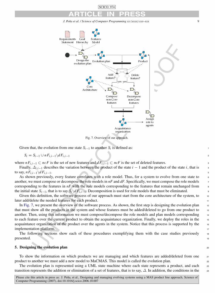
Fig. 7. Overview of our approach.
Given that, the evolution from one state Si−1 to another Si is defined as: 1
Si = Si−1 ∪ nFi,i−1\d Fi,i−1 2
where nFi,i−1 ⊂ ncF is the set of new features and d Fi,i−1 ⊂ ncF is the set of deleted features. 3
Finally, ∆i,i−1 describes the variation between the product of the state i − 1 and the product of the state i , that is 4
to say, nFi,i−1\d Fi,i−1. 5
As shown previously, every feature correlates with a role model. Thus, for a system to evolve from one state to 6
another, we must compose or decompose the role models in nF and dF. Specifically, we must compose the role models 7
corresponding to the features in nF with the role models corresponding to the features that remain unchanged from 8
the initial state Si−1, that is to say Si\d Fi,i−1. Decomposition is used for role models that must be eliminated. 9
Given this definition, the software process of our approach must start from the core architecture of the system, to 10
later add/delete the needed features for each product. 11
In Fig. 7, we present the overview of the software process. As shown, the first step is designing the evolution plan 12
that must show all the products in the system and whose features must be added/deleted to go from one product to 13
another. Then, using this information we must compose/decompose the role models and plan models corresponding 14
to each feature over the current product to obtain the acquaintance organization. Finally, we deploy the roles in the 15
acquaintance organization of the product over the agents in the system. Notice that this process is supported by the 16
implementation platform. 17
The following sections show each of these procedures exemplifying them with the case studies previously 18
presented. 19
5. Designing the evolution plan 20
To show the information on which products we are managing and which features are added/deleted from one 21
product to another we must add a new model to MaCMAS. This model is called the evolution plan. 22
The evolution plan is represented using a UML state machine where each state represents a product, and each 23
transition represents the addition or elimination of a set of features, that is to say, ∆. In addition, the conditions in the 24
Please cite this article in press as: J. Pena, et al., Designing and managing evolving systems using a MAS product line approach, Science ofComputer Programming (2007), doi:10.1016/j.scico.2006.10.007
UN
CO
RR
ECTE
DPR
OO
F
SCICO: 974
ARTICLE IN PRESS10 J. Pena et al. / Science of Computer Programming xx (xxxx) xxx–xxx
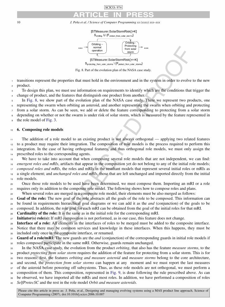
Fig. 8. Part of the evolution plan of the NASA case study.
transitions represent the properties that must hold in the environment and in the system in order to evolve to the new1
product.2
To design this plan, we must use information on requirements to identify which are the conditions that trigger the3
change of product, and the features that distinguish one product from another.4
In Fig. 8, we show part of the evolution plan of the NASA case study. There we represent two products, one5
representing the swarm when orbiting an asteroid, and another representing the swarm when orbiting and protecting6
from a solar storm. As can be seen, we add or delete the feature corresponding to protecting from a solar storm7
depending on whether or not the swarm is under risk of solar storm, which is measured by the feature represented in8
the role model of Fig. 3.9
6. Composing role models10
The addition of a role model to an existing product is not always orthogonal — applying two related features11
to a product may require their integration. The composition of role models is the process required to perform this12
integration. In the case of having orthogonal features, and thus orthogonal role models, we must only assign the13
prescribed roles to the corresponding agents.14
We have to take into account that when composing several role models that are not independent, we can find:15
emergent roles and mRIs, artifacts that appear in the composition yet do not belong to any of the initial role models;16
composed roles and mRIs, the roles and mRIs in the resultant models that represent several initial roles or mRIs as17
a single element; and unchanged roles and mRIs, those that are left unchanged and imported directly from the initial18
role models.19
Once those role models to be used have been determined, we must compose them. Importing an mRI or a role20
requires only its addition to the composite role model. The following shows how to compose roles and plans.21
When several roles are merged in a composite role model, their elements must be also merged as follows:22
Goal of the role: The new goal of the role abstracts all the goals of the role to be composed. This information can23
be found in requirements hierarchical goal diagrams or we can add it as the and (conjunction) of the goals to be24
composed. In addition, the role goal for each mRI can be obtained from the goal of the initial roles for that mRI.25
Cardinality of the role: It is the same as in the initial role for the corresponding mRI.26
Initiator(s) role(s): If mRI composition is not performed, as in our case, this feature does not change.27
Interface of a role: All elements in the interfaces of roles to be merged must be added to the composite interface.28
Notice that there may be common services and knowledge in these interfaces. When this happens, they must be29
included only once in the composite interface, or renamed.30
Guard of a role/mRI: The new guards are the and (conjunction) of the corresponding guards in initial role models if31
roles composed participate in the same mRI. Otherwise, guards remain unchanged.32
In the NASA case study, the evolution from the product orbiting, that also has the feature measure storms, to the33
product protecting from solar storm requires the addition of the feature for protecting from a solar storm. This is for34
two reasons: first, the features orbiting and measure asteroid and measure storms belong to the core architecture,35
and second, the protection from solar storms can happen at any moment and we must report the last measures36
of the asteroid before powering off subsystems. Thus, as these role models are not orthogonal, we must perform a37
composition of them. This composition, represented in Fig. 9, is done following the rule prescribed above. As can38
be observed, we have imported all the mRIs and most roles. In addition, we have performed a composition of roles39
SelfProtecSC and the rest in the role model Orbit and measure asteroids.40
Please cite this article in press as: J. Pena, et al., Designing and managing evolving systems using a MAS product line approach, Science ofComputer Programming (2007), doi:10.1016/j.scico.2006.10.007

UN
CO
RR
ECTE
DPR
OO
F
SCICO: 974
ARTICLE IN PRESSJ. Pena et al. / Science of Computer Programming xx (xxxx) xxx–xxx 11
Fig. 9. Composed role model.
Fig. 10. Composed plan.
The composition of plans consists of setting the order of execution of mRIs in the composite model, using the role 1
model plan or role plans. We provide several algorithms to assist in this task: extraction of a role plan from the role 2
model plan and vice versa, and aggregation of several role plans; see [12] for further details of these algorithms. 3
Thanks to these algorithms, we can keep both plan views consistent automatically. Depending on the number of 4
roles that have to be merged we can base the composition of the plan of the composite role model on the plan of roles 5
or on the plan of the role model. Several types of plan composition can be used for role plans and for role model plans: 6
Please cite this article in press as: J. Pena, et al., Designing and managing evolving systems using a MAS product line approach, Science ofComputer Programming (2007), doi:10.1016/j.scico.2006.10.007

UN
CO
RR
ECTE
DPR
OO
F
SCICO: 974
ARTICLE IN PRESS12 J. Pena et al. / Science of Computer Programming xx (xxxx) xxx–xxx
Fig. 11. Role model of issue resolution and change chair.
Please cite this article in press as: J. Pena, et al., Designing and managing evolving systems using a MAS product line approach, Science ofComputer Programming (2007), doi:10.1016/j.scico.2006.10.007

UN
CO
RR
ECTE
DPR
OO
F
SCICO: 974
ARTICLE IN PRESSJ. Pena et al. / Science of Computer Programming xx (xxxx) xxx–xxx 13
Fig. 12. Role model plan of issue resolution and change chair.
Sequential: The plan is executed atomically in sequence with others. The final state of each state machine is 1
superimposed with the initial state of the state machine that represents the plan that must be executed, except the 2
initial plan that maintains the initial state unchanged and the final plan that maintains the final state unchanged. 3
Interleaving: To interleave several plans, we must build a new state machine where all mRIs in all plans are taken 4
into account. Notice that we must usually preserve the order of execution of each plan to be composed. We can use 5
algorithms to check behavior inheritance to ensure that this constraint is preserved, since to ensure this property, the 6
composed plan must inherit from all the initial plans [7]. 7
The composition of role model plans has to be performed following one of the plan composition techniques 8
described previously. Later, if we are interested in the plan of one of the composed roles, as it is needed to assign 9
the new plan to the composed roles, we can extract it using the algorithms mentioned previously. 10
We can also perform a composition of role plans following one of the techniques to compose plans described 11
previously. Later, if we are interested in the plan of the composite role model, for example for testing, we can obtain 12
it using the algorithms mentioned previously. 13
In Fig. 10, we show the composed plan for the NASA case study. This plan follows an interleaving composition 14
where we include the mRI report measures before starting the protection from the solar storm. Notice that when 15
finishing the solar storm, the system will evolve to the other product deleting the feature solar storm protection. Then, 16
the plan of the feature orbiting and measure will start from its initial state, thus restarting the exploration of the 17
asteroid. 18
7. Decomposition of role models 19
In this case, we have to remove some features of the system. Given that the evolution plan gives us the information 20
on the features to be removed and that there is a direct correlation between the features models and the models of the 21
architecture, we can identify which role model must be removed. 22
Regarding the UN case study, we assume that the current product contains the feature for issuing a resolution and 23
the feature for changing the chair. The role model is presented in Fig. 11, and in Fig. 12 we present the plan. 24
As can be observed, the roles that we can find in this system are the chair, the observer, the voter, and the submitter. 25
These roles are mapped onto the UN countries forming the structural organization/software architecture. Notice that 26
these countries change over time; thus, the software architecture must also change. However, as our approach separates 27
Please cite this article in press as: J. Pena, et al., Designing and managing evolving systems using a MAS product line approach, Science ofComputer Programming (2007), doi:10.1016/j.scico.2006.10.007

UN
CO
RR
ECTE
DPR
OO
F
SCICO: 974
ARTICLE IN PRESS14 J. Pena et al. / Science of Computer Programming xx (xxxx) xxx–xxx
Fig. 13. Role model without change chair.
the roles from the concrete agents that play them, these changes can be easily deployed in the software architecture1
just changing the assignation of roles to agents, supported by the implementation platform.2
In addition, we can observe a set of mRIs that represent the joint processes that are performed by the agents that3
play these roles. The mRIs we found are submit, that represents the submission of a new proposal; vote, that shows4
how an agent playing the role voter produces its vote; withdraw, that shows the process of quitting a proposal for5
resolution; accept/reject, that represents the process of counting the votes, decide if the resolution is accepted or not,6
and inform all the observers; finally, the change chair mRI, that represents how the tasks of an old chair are transferred7
to a new chair.8
The decomposition is simpler than composition. When the features to be eliminated are orthogonal to the restin the9
Please cite this article in press as: J. Pena, et al., Designing and managing evolving systems using a MAS product line approach, Science ofComputer Programming (2007), doi:10.1016/j.scico.2006.10.007

UN
CO
RR
ECTE
DPR
OO
F
SCICO: 974
ARTICLE IN PRESSJ. Pena et al. / Science of Computer Programming xx (xxxx) xxx–xxx 15
product, we only have to delete the corresponding roles, and its mRIs, from the agents that are playing them. 1
In the case where the role model of the feature is dependent on others, we have to delete the elements of role 2
models and eliminate all the interactions that refer to them. Given that, in the software architecture we have described, 3
the implementation platform supports the role concept and its changes at run time, the above-mentioned changes can 4
be made easily with a lower impact on the system. 5
However, features may appear whose role models involve a dependency. In these cases, some roles may have to be 6
decomposed. These roles are those whose mRIs belong to the scope of the role model(s) that have to be eliminated. In 7
these cases, the role has to be decomposed into several roles, in order to isolate the part of the role we want to delete. 8
This is done by deleting from the interface of these roles the information used by the mRIs to be deleted. 9
In addition, we have to eliminate the mRI(s) of the role model(s) to be eliminated from the role model plan or 10
the role plans. This is done starting from the plan of the initial dependent role models. Each separate role model 11
usually maintains the order of execution of mRIs determined in the initial model but executes only a subset of mRIs 12
of the initial role models. The behavior of the role model to be deleted can be extracted automatically using the 13
algorithms described in [12]. This algorithm allows us to extract the plan of remaining role models from the initial 14
ones constraining this to the set of mRIs that remains in the model. 15
Regarding the UN case study, if a war is happening and changing the chair is prohibited we must decompose it 16
from the current product. This leads us to start from the model presented previously to, using the decomposition of 17
role models, remove all the elements related to the change chair feature from both the role model and the plan model. 18
As can be observed, to delete the change chair mRI we have to remove all the roles related to it. The NewChair 19
role is not further related to other roles or mRIs, so that they can be deleted. 20
However, the Chair role is involved in the change chair feature and in the issue resolution; thus it is dependent on 21
the feature issue resolution. Given that, we must decompose it to obtain a new role that does not take into account the 22
change chair feature. The mRI change chair uses the information programmed tasks of the Chair role as input, and 23
the information future tasks of the NewChair role as output. 24
Thus, we have just to delete the information programmed tasks from the role Chair. The resultant role model is 25
shown in Fig. 13. 26
Regarding the plan model, we can apply the algorithm to constrain a plan to a set of mRIs, presented in [12], 27
obtaining the role model plan of Fig. 14. 28
8. Conclusions and future work 29
We have described a novel approach to describing, understanding, and analyzing evolving systems. Our approach 30
is based on viewing different instances of a system as it evolves as different “products” in a software product line. 31
That software product line is in turn developed with an agent-oriented software engineering approach and views 32
the system as a multiagent system product line. The use of such an approach is particularly appropriate as it allows us 33
to scale our view to address enterprise architectures where various entities in the enterprise are modeled as software 34
agents as we have seen in the human organization case study. 35
The main advantage of the approach resides in the fact that it allows us to derive a formal model of the system 36
and of each state that it may reach. This allows us to clearly specify the differences from one state of the architecture 37
and any subsequent states of that evolving system. This significantly improves our capabilities for understanding, 38
analyzing and testing evolving systems. Additionally, thanks to the use of MaCMAS which allows for the description 39
of the same feature at different levels of abstraction, we can also specify and test the architectural changes at different 40
levels of abstraction. 41
Finally, such an approach provides support at run time for the addition and deletion of roles in the architecture. 42
It provides refiection mechanisms that enable understanding of the features, roles, and agents in an enterprise 43
architecture at different levels of abstraction, providing capabilities for ensuring quality of service by means of 44
self-organization, self-protection, and other self-* properties identified by the Autonomic Computing initiative. 45
Furthermore, it decreases the distance between enterprise architectures and software architectures, enabling us to 46
model enterprise architectures as software architectures and exploit all of the advantages of software architecture 47
approaches. 48
Please cite this article in press as: J. Pena, et al., Designing and managing evolving systems using a MAS product line approach, Science ofComputer Programming (2007), doi:10.1016/j.scico.2006.10.007

UN
CO
RR
ECTE
DPR
OO
F
SCICO: 974
ARTICLE IN PRESS16 J. Pena et al. / Science of Computer Programming xx (xxxx) xxx–xxx
Fig. 14. Role model plan without change chair.
References1
[1] S. Brueckner, H.V.D. Parunak, Resource-aware exploration of the emergent dynamics of simulated systems, in: Proceedings of Autonomous2
Agents and Multi Agent Systems, AAMAS, 2003, pp. 781–788.3
[2] K. Czarnecki, U. Eisenecker, Generative Programming: Methods, Tools, and Applications, Addison-Wesley, 2000.4
[3] D. D’Souza, A. Wills, Objects, Components, and Frameworks with UML: The Catalysis Approach, Addison-Wesley, Reading, MA, 1999.5
[4] A. Jansen, R. Smedinga, J. Gurp, J. Bosch, First class feature abstractions for product derivation, IEE Proceedings Software 151 (4) (2004)6
187–198.7
[5] K. Kang, S. Cohen, J. Hess, W. Novak, A. Peterson, Feature-oriented domain analysis (foda) feasibility study, Technical Report CMU/SEI-8
90-TR-021, Software Engineering Institute, Carnegie-Mellon University, November 1990.9
[6] E.A. Kendall, Role modeling for agent system analysis, design, and implementation, IEEE Concurrency 8 (2) (2000) 34–41.10
[7] B. Liskov, J.M. Wing, Specifications and their use in defining subtypes, in: Proceedings of the Eighth Annual Conference on Object-Oriented11
Programming Systems, Languages, and Applications, ACM Press, 1993, pp. 16–28.12
[8] J. Odell, FIPA, The FIPA agent UML web site, since 2003. Available at www.auml.org.13
[9] J. Odell, H. Parunak, M. Fleischer, The role of roles in designing effective agent organisations, in: A. Garcia, C.L.F.Z.A.O.J. Castro (Eds.),14
Software Engineering for Large-Scale Multi-Agent Systems, in: LNCS, vol. 2603, Springer-Verlag, Berlin, 2003, pp. 27–28.15
[10] H.V.D. Parunak, J. Odell, Representing social structures in UML, in: J.P. Muller, E. Andre, S. Sen, C. Frasson (Eds.), Proceedings of the Fifth16
International Conference on Autonomous Agents, ACM Press, Montreal, Canada, 2001, pp. 100–101.17
[11] J. Pena, On improving the modelling of complex acquaintance organisations of agents. A method fragment for the analysis phase. Ph.D.18
Thesis, University of Seville, 2005.19
[12] J. Pena, R. Corchuelo, J.L. Arjona, Towards interaction protocol operations for large multi-agent systems, in: Proceedings of the 2nd Int.20
Workshop on Formal Approaches to Agent-Based Systems, FAABS 2002, NASA-GSFC, Greenbelt, MD, USA, in: LNAI, vol. 2699, Springer-21
Verlag, 2002, pp. 79–91.22
[13] J. Pena, M.G. Hinchey, A. Ruiz-Cortes, Multiagent system product lines: Challenges and benefits. Communications of the ACM (2006) (in23
press).24
[14] J. Pena, M.G. Hinchey, A. Ruiz-Cortes, P. Trinidad, Building the core architecture of a NASA multiagent system product line, in: 7th25
International Workshop on Agent Oriented Software Engineering 2006, Hakodate, Japan, in: LNCS, May 2006 (in press).26
[15] K. Pohl, G. Bockle, F. van der Linden, Software Product Line Engineering: Foundations, Principles and Techniques, Springer,27
September 2005.28
[16] T. Reenskaug, Working with Objects: The OOram Software Engineering Method, Manning Publications, 1996.29
[17] C. Rouff, M. Hinchey, W. Truszkowski, J. Rash, Experiences applying formal approaches in the development of swarm-based space30
exploration systems, in: Formal Methods in Industry, International Journal of on software Tools for Technology Transfer (2006) (special31
issue) (submitted for publication).32
[18] C. Rouff, A. Vanderbilt, M. Hinchey, W. Truszkowski, J. Rash, Formal methods for swarm and autonomic systems, in: Proc. 1st International33
Symposium on Leveraging Applications of Formal Methods, ISoLA, Oct 30–Nov 2, Cyprus, 2004.34
[19] C.A. Rouff, W.F. Truszkowski, J.L. Rash, M.G. Hinchey, A survey of formal methods for intelligent swarms, Technical Report TM-2005-35
212779, NASA Goddard Space Flight Center, Greenbelt, Maryland, 2005.36
[20] Y. Smaragdakis, D. Batory, Mixin layers: an object-oriented implementation technique for refinements and collaboration-based designs, ACM37
Transactions on Software Engineering and Methodology 11 (2) (2002) 215–255.38
[21] F. Zambonelli, N. Jennings, M. Wooldridge, Developing multiagent systems: The GAIA methodology, ACM Transactions on Software39
Engineering and Methodology 12 (3) (2003) 317–370.40
Please cite this article in press as: J. Pena, et al., Designing and managing evolving systems using a MAS product line approach, Science ofComputer Programming (2007), doi:10.1016/j.scico.2006.10.007
Related Documents