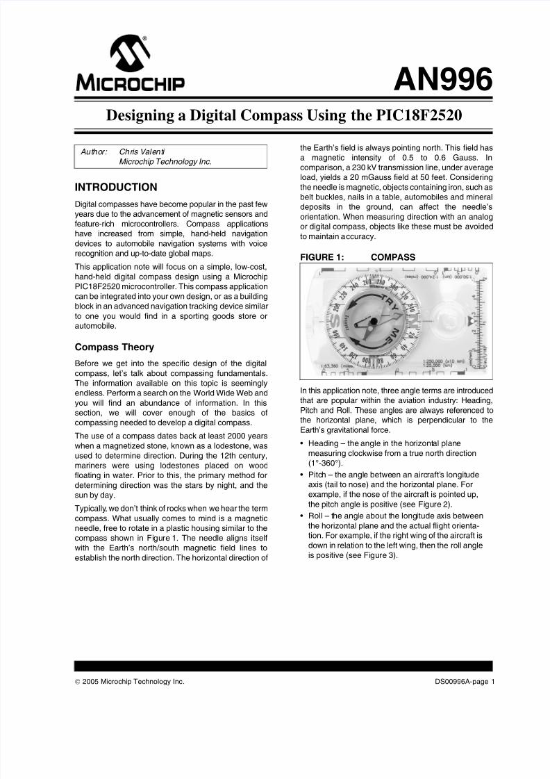
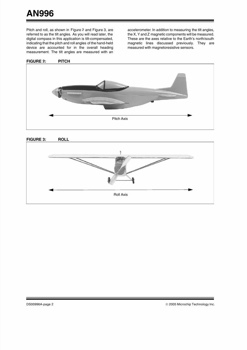
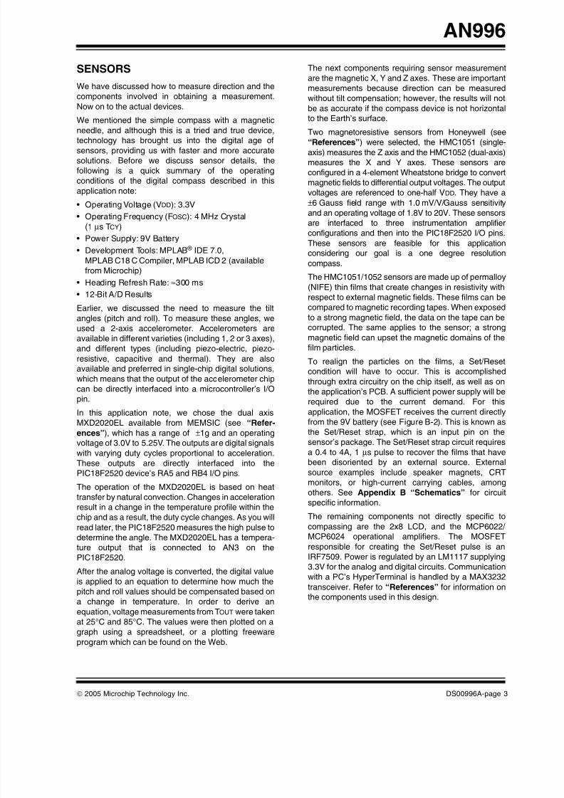
© 2005 Microchip Technology Inc. DS00996A-page 1 AN996 INTRODUCTION Digital compasses have become popular in the past few years due to the advancement of magnetic sensors and feature-rich microcontrollers. Compass applications have increased from simple, hand-held navigation devices to automobile navigation systems with voice recognition and up-to-date global maps. This application note will focus on a simple, low-cost, hand-held digital compass design using a Microchip PIC18F2520 microcontroller. This compass application can be integrated into your own design, or as a building block in an advanced navigation tracking device similar to one you would find in a sporting goods store or automobile. Compass Theory Before we get into the specific design of the digital compass, let’s talk about compassing fundamentals. The information available on this topic is seemingly endless. Perform a search on the World Wide Web and you will find an abundance of information. In this section, we will cover enough of the basics of compassing needed to develop a digital compass. The use of a compass dates back at least 2000 years when a magnetized stone, known as a lodestone, was used to determine direction. During the 12th century, mariners were using lodestones placed on wood floating in water. Prior to this, the primary method for determining direction was the stars by night, and the sun by day. Typically , we don’t think of rocks when we hear the term compass. What usually comes to mind is a magnetic needle, free to rotate in a plastic housing similar to the compass shown in Fi gure 1. The needle aligns itself with the Earth’s north/south magnetic field lines to establish the north direction. The horizontal direction of the Earth’s field is always pointing north. This field has a magnetic intensity of 0.5 to 0.6 Gauss. In comparison, a 230 kV transmission line, under average load, yields a 20 mGauss field at 50 feet. Considering the needle is magnetic, objects containing iron, such as belt buckles, nails in a table, automobiles and mineral deposits in the ground, can affect the needle’s orientation. When measuring direction with an analog or digital compass, objects like these must be avoided to maintain a ccuracy. FIGURE 1: COMPASS In this application note, three angle terms are introduced that are popular within the aviation industry: Heading, Pitch and Roll. These angles are always referenced to the horizontal plane, which is perpendicular to the Earth’s gravitational force. • Heading – the angle in the ho rizont al plan e measuring clockwise from a true north direction (1°-360°). • Pitc h – the angl e betwe en an aircraft’ s longit ude axis (tail to nose) and the horizontal plane. For example, if the nose of the aircraft is pointed up, the pitch angle is positive (see Fi gure 2). • Roll – t he angl e about t he long itude a xis bet ween the horizontal plane and the actual flight orienta- tion. For example, if the right wing of the aircraft is down in relation to the left wing, then the roll angle is positive (see Figure 3). Aut hor: Chr is Vale nt i Microchip Technology Inc. Designing a Digital Compass Using the PIC18F2520

Welcome message from author
This document is posted to help you gain knowledge. Please leave a comment to let me know what you think about it! Share it to your friends and learn new things together.
Transcript
8/3/2019 Designing a Digital Compass
http://slidepdf.com/reader/full/designing-a-digital-compass 1/18
8/3/2019 Designing a Digital Compass
http://slidepdf.com/reader/full/designing-a-digital-compass 2/18
8/3/2019 Designing a Digital Compass
http://slidepdf.com/reader/full/designing-a-digital-compass 3/18

8/3/2019 Designing a Digital Compass
http://slidepdf.com/reader/full/designing-a-digital-compass 4/18
8/3/2019 Designing a Digital Compass
http://slidepdf.com/reader/full/designing-a-digital-compass 5/18
8/3/2019 Designing a Digital Compass
http://slidepdf.com/reader/full/designing-a-digital-compass 6/18

8/3/2019 Designing a Digital Compass
http://slidepdf.com/reader/full/designing-a-digital-compass 7/18

8/3/2019 Designing a Digital Compass
http://slidepdf.com/reader/full/designing-a-digital-compass 8/18

8/3/2019 Designing a Digital Compass
http://slidepdf.com/reader/full/designing-a-digital-compass 9/18
8/3/2019 Designing a Digital Compass
http://slidepdf.com/reader/full/designing-a-digital-compass 10/18

8/3/2019 Designing a Digital Compass
http://slidepdf.com/reader/full/designing-a-digital-compass 11/18

8/3/2019 Designing a Digital Compass
http://slidepdf.com/reader/full/designing-a-digital-compass 12/18

8/3/2019 Designing a Digital Compass
http://slidepdf.com/reader/full/designing-a-digital-compass 13/18
8/3/2019 Designing a Digital Compass
http://slidepdf.com/reader/full/designing-a-digital-compass 14/18
8/3/2019 Designing a Digital Compass
http://slidepdf.com/reader/full/designing-a-digital-compass 15/18

8/3/2019 Designing a Digital Compass
http://slidepdf.com/reader/full/designing-a-digital-compass 16/18
8/3/2019 Designing a Digital Compass
http://slidepdf.com/reader/full/designing-a-digital-compass 17/18
8/3/2019 Designing a Digital Compass
http://slidepdf.com/reader/full/designing-a-digital-compass 18/18
Related Documents