Welcome message from author
This document is posted to help you gain knowledge. Please leave a comment to let me know what you think about it! Share it to your friends and learn new things together.
Transcript

Design Techniques for Multiband / Multimode
Radios
June 5, 2008
Steve Ellingson
Bradley Dept. of Electrical and Computer Engineering
Virginia Polytechnic Institute & State University

2Multiband RadioEllingson Jun 5, 2008
About the Instructor
Antennas, Signal Processing, Instrumentation
Ph.D., The Ohio State University, 2000
Experience: Assistant Professor, VT since 2003 Research Scientist, OSU ElectroScience Laboratory Systems Engineer, Raytheon (aka E-Systems, ERA) Consultant, Booz-Allen & Hamilton U.S. Army Officer (Signal Corps)
Email: [email protected]
Web Site: http://www.ece.vt.edu/swe/
Phone: (540) 231-2978
Steve
Ellingson

3Multiband RadioEllingson Jun 5, 2008
Outline of this Course
Introduction to Multiband/Multimode Radio (MMR)
Radio Design Basics
Antennas
Digitization
Sensitivity, Gain, and Noise
Linearity
Selectivity & Preselection
Conversion Architectures
RF CMOS
Antenna-Transceiver Interfacing
VT Public Safety MMR
Summary
Acknowledgements
References

4Multiband RadioEllingson Jun 5, 2008
What is a Band? Multiband?
This word is very casually used!
Functional definition: A band is a portion of the RF spectrum with distinct propagation characteristics and/or requiring radios with distinct technological characteristics
Log-scale bands: e.g., HF (3-30 MHz), VHF (30-300 MHz), ...
Often subdivided or application-specific: e.g., VHF-low, L-band
Regulatory definition: A portion of the RF spectrum allocated for a specific purpose
Examples: ISM (multiple), Cellular, PCS, Television (muliple), ...
A radio which is multiband works in multiple bands with little or no modification

5Multiband RadioEllingson Jun 5, 2008
Bands of the Electromagnetic Spectrum

6Multiband RadioEllingson Jun 5, 2008
l Multiband radios need to deal with strong out-of-band signals!
l 406-950 MHz has similar issues, but generally dynamic range requirements decrease with increasing frequency
l TV becomes digital (or dark) in Feb 2009
Example: 3-270 MHz in Columbus, OH [E05b]
HF
VHF
Lo
TV4 TV6 FM Broadcast
Aero/
Sat
Ham
VHF
Hi
TV10
Mostly low-level
until ~400 MHz
l Sensitivity: -87 dB(mW/[30 kHz])
l Red: Max-hold, Blue: Mean, Green: Load

7Multiband RadioEllingson Jun 5, 2008
What is a Mode?
Fundamentally, a method of communication.
Sometimes, just a modulation (e.g., NBFM, QPSK)
More often, a standard (e.g., TIA-603, IS-95)
Often, a complete protocol, perhaps including families of standards and perhaps even MAC and higher OSI layers (e.g., APCO Project 25, IEEE 802.11)
The FCC defines bands and constrains the allowed modes (and often, the allowed users) in each band.
History:
Radios traditionally use a single mode, because they are typically used for just one thing
Proliferation of non-standard or (worse!) proprietary modes
Desire or requirement for interoperability has led to increasing interest in multimode radios

8Multiband RadioEllingson Jun 5, 2008

9Multiband RadioEllingson Jun 5, 2008
Why Multiband/Multimode Radio (MMR) ?
Military
Interoperability a perpetual problem, becoming particularly acute with the advent of rapid joint service ops in the 1980s
Primary instigators for software-defined radio (SDR), but the underlying motivation is to have multiband/multimode capabilities.
Public Safety
Analogous to military application, except interest in interoperable radio is much more recent and cost is much bigger issue
All-in-ones and personal digital assistants (PDAs)
Emerging now because it is becoming practical
Dynamic spectrum & new paradigms for spectrum management
Multiband/multimode radio is enabling technology for these things
However, white space seek/detect is a new application
Down the road: Cognitive radio

10Multiband RadioEllingson Jun 5, 2008
Public Safety MMR Concept
Audio
Sw
itch /
IP R
oute
r
Selected VoiceChannels
Selected Data Channel
Combine Many Radios into One*
At least 13 bands relevant to Public Safety x Many channels per band = A lot of radios!
(*Above figure is just a functional description.)
Frequency Bands:
VHF LO (25-50 MHz)
VHF (138-174 MHz)
220 MHz
UHF (406-512 MHz)
700 MHz P.S.
800 MHz P.S.
Cellular & PCS
2.4 GHz ISM
4.9 GHz P.S.
Goal: Seamless Interoperability
l Many agencies would be delighted just
to have a single mode with 2 bands!
l In most cases, 3-4 bands (VHF-Hi, UHF,
and 700/800 MHz) would be Nirvana
l The real issue: Cost.

11Multiband RadioEllingson Jun 5, 2008
All-in-Ones
Illustration is from the
web page of
Bitwave Semiconductor
http://www.bitwave.com
FEM = Front End Module
Note that even if the radioelectronics are tightly integrated, antennas remain a problem
Design imparitives:(1) Cost(2) Size(3) Power consumption

12Multiband RadioEllingson Jun 5, 2008
Existing MMR (1/2)
Commercial Mobile Telecommunications (Cellular/PCS)
Low-cost 3- and 4-band transceivers widely available, primarily to accommodate regional and international roaming
Low cost possible because
Each band individually has small tuning range and is limited to one mode or a family of very similar modes
Modest performance requirements
Extremely large production volumes
Amateur Radio
High-performance low-cost 3- and 4-band handheld transceivers are widely available [E06].
Possible because each band individually has small tuning range, and operation is limited to AM and FM modes

13Multiband RadioEllingson Jun 5, 2008
Existing MMR (2/2)
Military; e.g., JTRS (DOD SDR program)
E.g., 5W HTs with 30-512 MHz continuous tuning and ~5 modes: Harris AN/PRC-152, Thales AN/PRC-148
High cost and somewhat compromized performance primarily due to requirement for continuous tuning over very large (>10:1) bandwidth and SDR-type (SCA) mode flexibility [E06].
Public Safety (Very recently introduced) [J08]:
Thales Liberty: 138-896 MHz in 4 bands; TIA603 & APCO P25
Harris RF-1033M: 30-512 MHz continuous; TIA603 & APCO P25
Common issues:
Capabilities: RF performance, tuning range and mode flexibility; Constraints: Cost, size, power consumption
The %$#@! antenna.

14Multiband RadioEllingson Jun 5, 2008
Why This Short Course?
MMR is in growing demand
MMR design issues and techniques are not as widely understood as those for traditional single-band / single-mode radio
MMR applications tend to demand more than what can be achieved by simply squeezing more radios and antennas into a single enclosure
High performance MMR is no problem until you put constraints on cost, size and power consumption!
Recent technical developments seem to be opening the door to practical MMRs with reasonable performance at reduced cost

15Multiband RadioEllingson Jun 5, 2008
What this Course Does and Does Not Cover
What this course does not cover:
Basic electronics (suggestions: [R97] and [SS98])
Software defined radio (suggestions: [R02] and [K05])
Dynamic spectrum and cognitive radio (except tangentially)
Detailed discussions of modes or applications
Our focus will be on:
Design issues & tradeoffs
Existing design options and limitations
Emerging trends in MMR
Fair warning:
I assume you have some familiarity with radio design issues, but if something is unfamiliar please ask!
I will tend to emphasize receive over transmit.

16Multiband RadioEllingson Jun 5, 2008
Outline of this Course
Introduction to Multiband/Multimode Radio (MMR)
Radio Design Basics
Antennas
Digitization
Sensitivity, Gain, and Noise
Linearity
Selectivity & Preselection
Conversion Architectures
RF CMOS
Antenna-Transceiver Interfacing
VT Public Safety MMR
Summary
Acknowledgements
References

17Multiband RadioEllingson Jun 5, 2008
Anatomy of a (Traditional) Radio
Antenna
(matching)
Duplexer or
T/R switch
LNA
PA
Mod
Useror
App.
DemodA (A)DRF IF/BB
A (A)DRF IF/BB

18Multiband RadioEllingson Jun 5, 2008
What We Need from an Antenna (1/2)
Reasonable pattern.
For mobiles and portables, fair if not omnidirectional
Transmit match: Should be well-matched over the frequency ranges of interest, so as not to reflect or absorb power excessively.
VSWR of 2:1 is good; 3:1 or greater is often tolerated.
Reflected TX power causes performance problems for RX and TX
Reflected TX power is wasted power. Impacts range and battery life.
Receive match: As part of the receiver, deliver the required sensitivity.
Note! This is not the same as being as being well-matched.
It is not uncommon for a receiver to deliver the theoretical best possible sensitivity even with VSWR up to 10:1 or higher!

19Multiband RadioEllingson Jun 5, 2008
What We Need from an Antenna (1/2)
Constant impedance over bands of interest. Barring that, impedance characteristics that do not lead to excessive Q when interfaced to the electronics
High efficiency, independently of how well antenna is matched. (Power should be transduced, not stored or dissipated.)
Helpful if terminals are of the same mode (single-ended or differential) as the transceiver interface(s)
Modern mobile/portable antennas are nearly always single-ended, whereas increasingly the electronics interfaces are differential
Herein lies room for improvement...
Size and shape acceptable to user
For mobiles and portables, this typically means either monopole-like, conformal, or embedded.

20Multiband RadioEllingson Jun 5, 2008
Multiband Antennas
Some rules of thumb:
A good linear antenna needs to be at least λ/8 at the lowest frequency of operation and is then limited to have fractional impedance bandwidth ~ 10%
A good conformal or embedded antenna can be smaller, but is typically limited to fractional impedance bandwidth ~ 1%
These numbers can be exceeded by a factor of 5 or so by trading off radiation efficiency
Antennas can often be made to be simultaneously effective at two widely-separated frequencies simultaneously. This can be extended to 3, 4, 5 or more bands with increasing difficulty and decreasing fractional bandwidth and efficiency.
If this is not good enough, you can swap antennas. Of course, this irritates users and precludes simultaneous or agile multiband operation.
Another alternative is to integrate multiple antennas. Typically, handheld radios are limited to one protruding linear antenna and 2-3 emedded/conformal antennas. Gets complicated fast!

21Multiband RadioEllingson Jun 5, 2008
Effective Limits of Contiguous Antenna Bandwidth
For transmit, impedance matching is paramount, and the pattern typically does not vary much over the resulting (~10%) bandwidth
For receive, it is possible to get into trouble:
For an omnidirectional antenna, maximum dimension roughly 1.5 times first resonance (roughly λ/4 for a monopole) because pattern becomes funky as antenna becomes larger than this
VSWR becomes unacceptable (electrically short, matching entails excessive Q) for frequencies less than about ½ times resonance.
Therefore, the best possible usable antenna has bandwidth ~ 3:1.
The whole range can be used for receive, with only sensitivity degredation.
The whole range can be used for transmit but only about 1-10% BW can be used at any given time due to matching requirement.

22Multiband RadioEllingson Jun 5, 2008
Ooi (Motorola) (2005) [O05]
10%
Example: 700/800 MHz Monopole
New (hybrid) antennaλ/4 monopoleNormal-mode helical
5T
5 mm2.3 cm
14.6 cm
50 mm
x
130 mm
4 mmpolyurethane
sheath
VSWR
3:1
2:1
Freq [GHz]
Antenna is 0.43λ at 770 MHz, 0.35λ at 620 MHz
Traditional approaches are <2:1 in 790-880 MHz
New antenna is < 3:1 in 620-920 MHz
Tradeoff is apparent...

23Multiband RadioEllingson Jun 5, 2008
Example: Dual Band (Cellular/PCS) PIFA
Antenna is about 0.13λ at 900 MHz
About 6% bandwidth at 900 MHz
No problem to get two bands in a small conformal package, but:
Note radiation efficiency is only 50%-70%
Much recent activity in this area number of simultaneous bands up to 5, but always with tradeoffs...
Faraone et al. (Motorola) (2007) [F+07]

24Multiband RadioEllingson Jun 5, 2008
What About UWB Antennas?
UWB antennas will usually not be a reasonable alternative to traditional antennas
A common misconception is that UWB antennas are electrically small, where in fact the opposite is true: They tend to be relatively large because they require low reactance at lowest operational frequency.
Furthermore, antennas for UWB systems are properly designed for optimum transient response - Broadband nature is a result, not a requirement. Consequences are:
Relatively poor/volatile impedance characteristics over specified bandwidth
Awkward shapes

25Multiband RadioEllingson Jun 5, 2008
Outline of this Course
Introduction to Multiband/Multimode Radio (MMR)
Radio Design Basics
Antennas
Digitization
Sensitivity, Gain, and Noise
Linearity
Selectivity & Preselection
Conversion Architectures
RF CMOS
Antenna-Transceiver Interfacing
VT Public Safety MMR
Summary
Acknowledgements
References

26Multiband RadioEllingson Jun 5, 2008
Basics of A/D Conversion
Most modern high-speed ADCs encode full scale at ~1 Vpp @ 50Ω,
and therefore clip around PFS ~ +10 dBm
Quantization noise power for full scale input is usually just about -6Nb
dB relative to full scale power. (Actual value is -6.02Nb-1.76, but
analog imperfections result in an additional few dB noise generation)
Quantization noise is white only if input is white. Inputs containing lots of tones result in quantization tones as well as noise!
In addition, nonlinearity in the ADC transfer function results in intermodulation products. This often becomes the dominant problem as Nb is increased. Impact depends on application (e.g., modulation
of interest)

27Multiband RadioEllingson Jun 5, 2008
The A/D Conversion Nb-Fs Dilemma
Presently, A/Ds suitable for noise-limited coherent-sampling up to about 200 MSPS and 14 bits are commonly available. But....
In general, a quantization dynamic range bandwidth product which is achieved at a given sample rate Fs and Nb can also be achieved at a
higher Fs and lower Nb, through decimation.
When digitizing large bandwidths, A/D linearity is extremely important due to the profusion of narrowband signals. This tends to favor increasing Fs (and decimating) rather than increasing Nb.
Unfortunately, A/Ds can be major power hogs in any transceiver.
For any given ADC technology, power consumption is proportional to Fs * 10^(0.6Nb) [KA00].
By itself, this tends to favor increasing Nb rather than Fs

28Multiband RadioEllingson Jun 5, 2008
Sensitivity and Gain
The purpose of total gain G is to hoist the received signal over the quantization noise and IMD of the A/D (or, classically, over the detection threshold of an analog demodulator)
However, gain which introduces excessive additional noise defeats the purpose. This is traditionally quantified in terms of the noise figure, F, which in turn determines the minimum detectible signal (MDS):
MDS = δkTABsF (referenced to input), where
δ = minimum SNR considered a detectionk = Boltzmann's constant (1.38 x 10⁻²³ J/K)TA = Antenna temperature: Often taken as 290 K, but
could be more or less than this (stay tuned...)BS = Detection bandwidth ( ~ modulation bandwidth)
In a well-designed receiver, F is nominally dominated by the first amplifier in the signal path since it can only be degraded, not improved. Hence, the low noise amplifier (LNA).

29Multiband RadioEllingson Jun 5, 2008
How to Specify F and G
Note we have three sources of noise: The environment (TA), the front
end (F), and ADC quantization.
Generally we prefer:
Environmental noise to dominate over front end noise if possible: This sets F (more on this later)
Environmental + front end noise to dominate over quantization noiseThis sets G (defined from antenna terminals to ADC input):
k T AB F GG P FS100.6N
b
r PFSPA
GG PFS10
0.6Nb
k T AB FBandwidth presented
to the ADC
Desired marginof dominance
Desired ADC headroom
Total power at antenna terminals(including signals)

30Multiband RadioEllingson Jun 5, 2008
Example Gain Specification (and MDS)
G=10dBPFS=10dBmN b=12bitsT A=290K
B=1 MHzF=6dB
r=10dBPA=40dBm
40dBG86dB
r PFSPA
GG PFS10
0.6Nb
k T AB F
Desireability of
variable gain and/or
AGC is apparent.
MDS=k T ABS F=121 dB
3 dB detection threshold,
25 kHz bandwidth

31Multiband RadioEllingson Jun 5, 2008
MDS Specification?
Procedure in previous slides presumes you are looking for the best possible sensitivity
More often, sensitivity (MDS) is specified, which then sets F.
Example: TIA-603C (NBFM) requires MDS at least -116 dBm
Manufacturers frequently have their own internal rules of thumb on how much better or worse than this they will strive for
Should note that arbitrarily requiring a certain MDS offers no guarantee that the resulting F is optimal in any sense, unless environmental noise is taken into account.
Further, F might be overspecified! This is surprisingly easy to do at VHF and below. The consequences are pretty severe, as we shall see.

32Multiband RadioEllingson Jun 5, 2008
External (Environmental) Noise
Standard deviation with respect to location
Compiled from [ITU03] and [E05a] by S.M. Shajedul Hasan
b
A afT
[K ]

33Multiband RadioEllingson Jun 5, 2008
External (Environmental) Noise
b
A afT
Mean antenna noise
temperature is well-
modeled as a power
law in frequency:

34Multiband RadioEllingson Jun 5, 2008
Optimum Noise Figure
Courtesy of S.M. Shajedul Hasan
This is the noise
figure required of an
amplifier attached to
an antenna if the
output is to be
dominated by
external noise by a
factor of 10 in 90%
of locations of the
indicated type.
Optimum in the
sense that any
lower noise figure
does not
significantly
increase sensitivity
(only cost).
These particular
results assume
lossless, perfectly
matched antenna
with no ground loss.

35Multiband RadioEllingson Jun 5, 2008
Amp Connected Directly to Antenna
AT
kT A f 12 G p
pTpG
kT p f G p
Antenna looses up to ~½
of available power into
ground
Amp Gain
Amp Noise Temp.
(typ. 10s to 100s of K)
Refl.
Coef.
Total Noise Power Delivered to Radio:
Ratio of (irreducible) external noise
to (reducible) amp noise: =TA
T p 12

36Multiband RadioEllingson Jun 5, 2008
Note that
acceptable noise
performance is
being achieved for
very large VSWR.
Note improving Ta
has no effect on
sensitivity once
is large save your
money!
Improving Tp does
improve bandwidth
over which is
large
=1
Referenced to
antenna terminals
From [E05a]
Large Mismatch is OK at VHF (for RX...)

37Multiband RadioEllingson Jun 5, 2008
Outline of this Course
Introduction to Multiband/Multimode Radio (MMR)
Radio Design Basics
Antennas
Digitization
Sensitivity, Gain, and Noise
Linearity
Selectivity & Preselection
Conversion Architectures
RF CMOS
Antenna-Transceiver Interfacing
VT Public Safety MMR
Summary
Acknowledgements
References

38Multiband RadioEllingson Jun 5, 2008
Linearity
Warning! Not completely general (tangent factor, memory [R98])
Single tone input: Compression plus harmonics
Two-tone input: Above plus ω1+/-ω2 (2nd order IMD)
plus ω1+/-2ω2, 2ω1+/-ω2 (3rd order IMD)
...
vout t =1 v in t 2 v in2 t 3 v in
3 t ...

39Multiband RadioEllingson Jun 5, 2008
Compression (P1)

40Multiband RadioEllingson Jun 5, 2008
Intermodulation (IP2, IP3)
While the IP3 concept is often useful, it can also be quite misleading!([C+05], [C07])
Useful trivia: Taylor series modelpredicts IP3/P1 = +9.6 dB,independent of coefficients.
Most wireless protocols requireinput IP3 (IIP3) in the range-5 dBm to -20 dBm

41Multiband RadioEllingson Jun 5, 2008
Sensitivity-Linearity Tradeoff
Typically, improvements in F and IIP3 (or any linearity parameter) are mutually exclusive.
Incidently, this is true even within the preamplifier (LNA)!

42Multiband RadioEllingson Jun 5, 2008
Implications for MMR
HF and VHF-Lo receivers need less G and can tolerate higher F because external noise is so very high. This is good because linearity is a huge problem.
VHF-Hi and UHF receivers need moderate G and F because external noise is moderate. However the linearity requirements can be as bad or worse than at HF.
At higher frequencies, it is relatively rare to be linearity-constrained (exception: PCS bands). This is good because high G and low F is required for outdoor mobile applications.
If our MMR is to span these bands, we have the additional demand of needing to simultaneously satisify these disparate requirements!
The answer is usually selectivity.

43Multiband RadioEllingson Jun 5, 2008
Selectivity
Selectivity is bandpass filtering: This is key to mitigating intermodulation effects and simplifying design problems in all kinds of receivers.
RF (front end) selectivity is desirable to exclude potential sources of compression, harmonics, and intermodulation
In superhets, IF band selectivity is desirable to suppress intermodulation at frequencies not of interest (to avoid reentrance later)
Useful primer on filter design in receiver context: [H+07]

44Multiband RadioEllingson Jun 5, 2008
Receiver Design Tradeoffs
Sensitivity
Linearity Selectivity
CostSize & Weight
Power

45Multiband RadioEllingson Jun 5, 2008
Preselection
Preselection refers to the implementation of selectivity before frequency conversion.
Typically not an issue for single-band radios operating over narrow fractional bandwidth a single RF filter is adequate
For multiband operation or operation over large frequency ranges, we typically need some way to exclude large signals not-of-interest
Fixed TuningMultiplexing
Band 1
Band 2
Band N
.
.
.

46Multiband RadioEllingson Jun 5, 2008
Park & Rebeiz (2008) [PR08]
Example: Compact Varactor Tuner
850-1400 MHz
BW ~ 5%
IL < 3 dB
IP3 > 11 dBm

47Multiband RadioEllingson Jun 5, 2008
Example: Compact Switched Capacitor TunerPaulsen & Spenser (2007) [PS07]
30-88 MHz
IL ~ 5 dB
256 states
PIN diode switches
Control logic in Multichip Module (MCM)
0.666 in2 footprint

48Multiband RadioEllingson Jun 5, 2008
Preselection using Diplexers
A diplexer is a passive bidirectional device that combines 2 spectrally-disjoint ports to a single controlled-impedance common port.
This is superior to power combining/splitting since insertion loss is minimized, return loss is frequency-independent, and you get selectivity essentially for free
Diplexers have many other uses in radio systems: duplexing, connecting a single radio to multiple antennas, and post-mixer absorbitive spurious suppression
Useful references: [MYJ80] (theory), [S99] (a useful design methodology)
Contiguous Band-Selective
Specifiedimpedance
vs. freq.(typically, Z0)
High-pass
Low-pass
Band 1
Band 2

49Multiband RadioEllingson Jun 5, 2008
RF Multiplexers
Diplexers are quite easy to design and implement as long as we stick with terminations that are:
Frequency-independent
Single-ended
real-valued impedances
More than two channels are possible; under the above conditions. This is called a multiplexer. Recently compact multiplexers with very large numbers of channels have become practical; see e.g., [G+08].
When the common port impedance is frequency-dependent and possibly reactive, things get interesting.
Becoming important because this is the case when we connect multiplexers directly to compact wideband/multiband antennas!
Recent thinking on this is described in [WM07].
50Multiband RadioEllingson Jun 5, 2008
Outline of this Course
Introduction to Multiband/Multimode Radio (MMR)
Radio Design Basics
Antennas
Digitization
Sensitivity, Gain, and Noise
Linearity
Selectivity & Preselection
Conversion Architectures
RF CMOS
Antenna-Transceiver Interfacing
VT Public Safety MMR
Summary
Acknowledgements
References

51Multiband RadioEllingson Jun 5, 2008
Conversion Architectures
Receive (details in slides to follow):
Direct Sampling / Undersampling
Superheterodyne (Superhet)
Direct Conversion a.k.a Zero-IF
Low-IF
The Menagerie: Hartley, Weaver, Hybrids
Transmit:
Mirror image of receive in many cases. This simplifies frequency planning & reduces number of local oscillators (LOs)
Sometimes, modulation dependent: e.g., NBFM exciters
Our emphasis will be on receive, but we will try to address some of the transmit issues as well.

52Multiband RadioEllingson Jun 5, 2008
Direct Sampling
All the gain and selectivity is at RF. (When the backend is something other than a digitizer, this is Tuned RF.)
Digitization requires sample rate more (typically much more) than twice highest bandwidth of interest. ADCs (DACs) with sufficient speed and dynamic range typically do not exist, or are prohibitively power-hungry.
Sometimes feasible at HF and low VHF frequencies, but typically ruled out for mobile/portable use due to power consumption.
Even if high power consumption is acceptable, RF design is a challenge.
IM2 concerns may limit tuning range to be less than 2:1
LNA
A DRF RF
Preselect

53Multiband RadioEllingson Jun 5, 2008
Example: 20-80 MHz Direct Sampling Receiver
Prototype receiver for the Long Wavelength Array (LWA) radio telescope (http://lwa.unm.edu)
G ~ 71 dBTp ~ 300K (F ~ 3 dB)
>10 in 29-47 MHzP1dB(in) = -3 dBm
12b @ 200 MSPS400 mA @ 12V + ADC
Craig, Harun & Ellingson (2008) [CHE08]

54Multiband RadioEllingson Jun 5, 2008
Undersampling
Undersampling is direct sampling when the passband is in contained within a Nyquist zone other than the first. However, also useful in superhets...
Spectral reversal for odd-numbered Nyquist zones (not a problem unless you forget about it...)
Clock jitter becomes performance-limiting in higher Nyquist zones
Excellent example of undersampling used to simultaneously receive GPS and GLONASS: [A+99]
From [B03]

55Multiband RadioEllingson Jun 5, 2008
Superheterodyne (Superhet)
RF is shifted to an intermediate frequency (IF), which is normally (but not always) lower in frequency.
From there, signal is:
Digitized; in which case we have an IF sampling receiver, or
Directly detected (e.g., classical AM/FM receivers), or
Converted again, in which case the IF is used primarily to provide selectivity and gain not possible at RF or baseband
LNAPreselect(Image Reject)
LO
Reject undesiredproducts
ADC
AM/FM Detection
Another conversion
IF

56Multiband RadioEllingson Jun 5, 2008
Superhets: Low-Side vs. High-Side Injection
x t =s t cos R t
x t cos L t =s t cos R t cos L t
=s t [1
2cos R L t
1
2cos R L t ]
Low-Side Injection (LSI):
L R : L R I : R L= I
High-Side Injection (HSI):
L R : L R I : R L= I
RF signal:
IF signal: Rejected mixing product
I
Works because cos() is even;however complex modulations become spectrally-reversed

57Multiband RadioEllingson Jun 5, 2008
Superhets: Image Rejection
Image Reject Diplexer
IF
L= IAn image is a solution to
The desired solution:
= Rother than
R= L± ILSIHSI
The image solution: R
i = L ILSIHSI R
i= R2 I
LSIHSI
Example: Mixing RF at 138 MHz to IF at 10.7 MHz using LSI:
116.6138.0
127.3
10.7
265.3127.3RF
Image Reject Diplexer
IF
Example: Mixing RF at 138 MHz to IF at 10.7 MHz using HSI:
148.7
RF159.4
138.0
286.7148.7 10.7
Note that
tuning range
increases with
increasing IF

58Multiband RadioEllingson Jun 5, 2008
Superhets: Half-IF Problem
From [R97]
Half-IF problem: IM2 from out-of-band interferer after mixing blocks desired IF frequency (Shown for HSI; same thing happens in LSI)
Poses quite a dilemma:
Further limit tuning range to exclude interfering signal, or
Greatly increase mixer IP2 (increase LO level, increase power consumption and LO isolation problems)
Same for both LSI and HSI
Half-IF problem:

59Multiband RadioEllingson Jun 5, 2008
Superhets: Tuning Range for LSI (1/2)
Image Reject Filter Response Fractional bandwidth
R
i L ,max R ,min
b2 I / L ,max
2 I
I R ,min / 2/b1Requires
Ex: RF = 138 MHz, LSI, b=0.1 (10%BW): Lowest IF = 6.6 MHz, tuning range ~ 0
(Increase IF to increase TR)
Highest tunable frequency: Image rejection requires:
R ,max
i R ,minb L ,max
R ,max 1b R ,min2b I
after substitution & some algebra:

60Multiband RadioEllingson Jun 5, 2008
Superhets: Tuning Range for LSI (2/2)
Maximum tuning ratio:
bTR R,max
R , min
=1b R ,min2b I
R ,min
= 1b2b I
R ,min
Minimum IF to support a specified tuning ratio:
I bTR1b
2b R , min
Example:
f R, min=138, f R ,max=174,b=0.1 bTR=1.261, f I=23.8

61Multiband RadioEllingson Jun 5, 2008
Superhets: Tuning Range for HSI (1/2)
Image Reject Filter Response Fractional bandwidth
R
i L ,min R ,max
b=2 I / L ,min
2 I
I R ,max / 2 /b1Requires
Ex: RF = 138 MHz, HSI, b=0.1 (10%BW): Lowest IF = 7.3 MHz
RF = 174 MHz, HSI, b=0.1 (10%BW): Lowest IF = 9.1 MHz
Highest tunable frequency: Image rejection requires:
R ,max
i R ,maxb L ,min
R ,max 1bb
I
after substitution & some algebra:

62Multiband RadioEllingson Jun 5, 2008
Superhets: Tuning Range for HSI (2/2)
Maximum tuning ratio:
bTR R,max
R ,min
=
1bb
I
R ,min
=1b
b
I
R ,min
Minimum IF to support a specified tuning ratio:
I bTR R ,min
b
1bExample:
f R,min=138, f R,max=174,b=0.1 bTR=1.261, f I=19.4
For a given tuning range and image filter selectivity, HSI tends to
accommodate lower minimum IF frequencies. However, interference in the
image band should be considered before choosing HSI over LSI.

63Multiband RadioEllingson Jun 5, 2008
Divide-and-Conquer Superhet
Decompose the problem into narrower tuning ranges to allow the use of simpler, higher-performance superhets
Main design challenges are frequency planning, and integration
Method of choice for present-day multiband handheld MMR
Complex, put reasonable power since only portion of radio is in used

64Multiband RadioEllingson Jun 5, 2008
Up-Down Superhet
Removes tuning range limit (from image rejection) by placing IF above RF.
Tuning range still may be limited to be less than 2:1 in order to avoid IM2 at RF
Cons compared to down-down superhets:
Tuning LO is higher frequency (cost, performance)
Often requires at least one more LO than an functionally equivalent down-down superhet (power consumption)
Fairly common for full coverage (3-30 MHz) HF base (non-mobile) receivers
Preselect(IM2
mitigation)LO
Reject undesiredproducts
IF2 (< RF)
LO
Reject undesiredproducts
RF
IF1 (> RF)

65Multiband RadioEllingson Jun 5, 2008
Up-Down Superhet for 138-894 MHz Continuous Tuning
ERA-3SM ERA-3SM ERA-3SM ERA-3SM ERA-3SM
DIPLEXER
1250 MHz
DIPLEXER
78 MHz
LARK
1250 MHz
LARK
1250 MHz
78 MHz
ERA-6SM ERA-3SM
SYM-11 SYM-11
FROM LO-1 FROM LO-2
TO
ADC
FROM
PRESELECTOR
Tuning range covers all public safety bands VHF-Hi to 800 MHz + cellular
IF1=1250 MHz (uses stock filters)
IF2=78 MHz accomodates 40 MHz BW in 2nd Nyquist zone at 104 MSPS
Intended for an IF-sampling SDR
Hasan & Ellingson (2006) [HE06]

66Multiband RadioEllingson Jun 5, 2008
Divide & Conquer Superhet with Up-Down Path
for 400-2000 MHz Continuous Tuning Ranu & Ellingson (2002) [RE02]

67Multiband RadioEllingson Jun 5, 2008
Superhet Summary
The primary advantages of the superhet are the ability to put gain and selectivity at frequencies other than RF.
Splitting gain between stages mitigates many practical problems
Putting selectivity at IF means a single fixed filter can be used
Most limitations of the superhet can be overcome using a divide and conquer approach, using preselection to narrow tuning range.
Given that the tuning range can be covered, it is hard to beat a superhet in terms of overall performance.
But, performance comes at a cost:
Synthesizer for each LO/IF stage power consumption and cost
Complex; high parts count
In divide and conquer systems, these problems are replicated in each parallel RF path.

68Multiband RadioEllingson Jun 5, 2008
RF converted to complex baseband using a single, tuning LO.
In some sense, this is the obvious thing to do: Simple (=cheap)!
Output already in I/Q form, as required by complex modulations. Sample rate is minimized, which in turn minimizes power consumption
But traditionally shunned. Issues include:
Direct Conversion
LNAPreselect(Image Reject)
LO
cos
sin
RF
BB-I
BB-Q

69Multiband RadioEllingson Jun 5, 2008
Direct Conversion Contraindications
Fundamental limitations [R97,LA02]:
Gain/phase imbalance at baseband
Limited rejection of undesired sideband (typically < 30 dB)
Degraded EVM
LO phase (1/f) noise ends up in band
DC offset creates tone jammer in center of band
Very high IP2 requirement at RF and at baseband
Additional practical difficulties:
IF is placed where the power supply noise is (i.e., near DC)
IM2s (as well as IM3s) are in-band
TX: LO reradiation (FCC doesn't like that...)
VCO pulling may require that LO be synthesized at a different frequency and divided down

70Multiband RadioEllingson Jun 5, 2008
Direct Conv. Limitations: Gain/Phase Imbalance
From [R+98]
Impact depends on modulation
I/Q correction straightforward, but usually awkward to implement
Test tones
Data-adaptive
Adaptive, low-if, no stimulus [GPO08]
From [LA02]

71Multiband RadioEllingson Jun 5, 2008
Direct Conv. Limitations: LO Phase Noise
Close-in phase noise (1/f noise) from the LO ends up in band
Extent of problem depends on bandwidth of signal-of-interest:
Huge problem for SSB
Major problem for GMSK (GSM)
Small or negligible problem for DSSS (as in CDMA or WiFi)
In fact, might even consider DC notch, which also mitigates of DC offset and power supply noise.
Possible solutions:
Improve LO: DDS! (becomes attractive especially in RF CMOS)
Chopping (again, particularly attractive in RF CMOS implementations)

72Multiband RadioEllingson Jun 5, 2008
Direct Conv. Limitations: DC Generation
Multiple causes
DC offset in either of the baseband paths creates tone jammer in center of band
Self-mixing i.e., LO feeding back into RF, puts tone at baseband
Effects
Unwelcome incursion on A/D dynamic range
Bigger problem for narrower modulations
Mitigation
Calibration (not so bad)
DC blocking caps (DC notch); also takes care of some power supply noise

73Multiband RadioEllingson Jun 5, 2008
Direct Conv. Limitations: High IP2 Required
Makes RF selectivity very important unfortunately one of the things that is awkward if wide tuning range is desired
Key to dealing with this as well as the self-mixing problem is common mode rejection.
This in turns screams out for differential-mode impementation:
From [BBH00]

74Multiband RadioEllingson Jun 5, 2008
Superhet with Direct Conversion Final Stage
Superhet contributes it's great selectivity and linearity characteristics
Maximum possible deference to ADC requirements; also convenient for I-Q modulated signals since signal is delivered in complex form
Probably most common approach currently for receivers doing anything other than analog modulations.
LNAPreselect(Image Reject)
LO
Reject undesiredproducts
LO
cos
sin
RF
IF
BB-I
BB-Q

75Multiband RadioEllingson Jun 5, 2008
Low IF Architecture
Same architecture as direct conversion except baseband center frequency is not zero.
Image sideband no longer overlaps; in fact selectivity is derived from the image rejection. This allows very wide tuning range if the I/Q balance is sufficiently good
Pros:
Avoid many of the problems of direct conversion / being near DC
Baseband IP2 can be less if IF is chosen to exclude in-band IM2
Cons:
ADC/DAC sample rates are increased by 2-3
DSP must subtract image sideband and retune signal
Very popular during 2G narrowband cellular development; now being eclipsed somewhat by new/improved direct conversion designs

76Multiband RadioEllingson Jun 5, 2008
Low-IF Wideband Transceiver for Ultra-High Field MRI
Application: Ultra-High Field (9T) Magnetic Resonance Imaging (MRI).
Tunes 10-400 MHz
Greater than 90 dB image rejection achieved through dynamic calibration NCOM
NCOM
A/D
A/D
DITHERGEN.
MRSIGNAL
LO
90°
BPF
BPF
DDFI
QDDF
90°
I
Q
DUC(NCOM)
I
Q
I
Q
DUC(NCOM)
I
Q
I
Q
D/A
D/A
2MSPS
32MSPS
LPF
LPF
LO
90°
16
16
32MSPS
Proof-of-concept testof receiver
Allows wide instantaneous bandwidth over a multiple-octave tuning range
Ellingson (2001) [E01]

77Multiband RadioEllingson Jun 5, 2008
So Where Do We Stand?
Other architectural options: Hartley, Weaver, combinations.
Emerging interest in improving RF performance by adaptive techniques:
Spectrum sensing and adaption to allow better performance with worse hardware [LD07]
Identifying and manipulating the performance-power tradeoff [T+07]
Summarizing: MMR is really no problem, as long as:
Cost is not an issue, or
Cost is an issue, but direct conversion class performance is OK
Since it is rare that either of the above are true, available solutions are typically dissapointing
Antenna limitations compound this problem

78Multiband RadioEllingson Jun 5, 2008
Outline of this Course
Introduction to Multiband/Multimode Radio (MMR)
Radio Design Basics
Antennas
Digitization
Sensitivity, Gain, and Noise
Linearity
Selectivity & Preselection
Conversion Architectures
RF CMOS
Antenna-Transceiver Interfacing
VT Public Safety MMR
Summary
Acknowledgements
References

79Multiband RadioEllingson Jun 5, 2008
Enter RF CMOS
Key idea: Implement RFICs using same dense, high-speed, inexpensive process used for modern digital circuitry
Useful background: [A04], [L04]
Key obstacles:
CMOS is fiendishly difficult to use for RF due to process variations and inaccurate design models
Very difficult to implement passive inductance
In recent years, these problems have been largely overcome by:
Learning to implement architectural approaches which are robust to process variations and inaccurate design models -- especially those using large numbers of small-valued capacitors
Exploiting availability to place dense logic to enable digitally-managed tweaking of chip as needed
Use of active inductors (gyrator = capacitor + impedance inverter) [L04]

80Multiband RadioEllingson Jun 5, 2008
Ways RF CMOS Changes the Problem
Very dense 90 nm now, 65 nm coming.
MMR can be implemented using multiple single-band transceivers on a single chip (whereas this would be very expensive to do with discrete transceivers)
Same substrate supports the digital logic which would otherwise be located elsewhere, allowing tight integration -- system on a chip: ADC/DAC, DDS-based LO synthesis, Baseband processing, Microcontroller and I/O functions
Reduced power requirements, especially since unused functions can be disabled
No free lunch: considerable tweaking may be required in circuit: Many parameters to be communicated over a low-speed serial port
Tight integration introduces a new problem noise mitigation. A key tool here (again) is differential signal transmission
Bottom line: Potential for acceptable performance at reduced cost

81Multiband RadioEllingson Jun 5, 2008
Importance of Differential-Mode Signals
Most of the sinful things that happen in RF CMOS (as well as other implementations!) are manifest as common mode signals
Undesired coupling (e.g., poor LO-to-RF isolation)
Noise from other (digital) processing on chip
IM2 generation
Fairly hopeless to deal with these when the desired signal is single-ended.
However, much can be done if the desired signal is differential [EST06].
Not a free ride though!
Antennas and external RF gadgets (like filters) are typically single-ended need balun
Differential performance depends on suppression of offsets, which can be a problem; can be addressed with feedback [A03]

82Multiband RadioEllingson Jun 5, 2008
The Balun Problem
Antennas and external RF gadgets (like filters) are typically single-ended need balun
A classical balun is a passive transformer which converts single-ended signals to differential form, possibly also converting impedance
Transformers have great linearity but finite bandwidth; 4:1 is typical
Space issue: A single SMT passive balun can have a footprint as large as the RFIC, and is roughly as high
Internal (CMOS) baluns are emerging... [GF08]
Challenging, because you can't use passive inductance!
As a result, these baluns are active
Pros: Tight integration, bandwidth
Cons: Linearity

83Multiband RadioEllingson Jun 5, 2008
Chopper Stabilization
fchop
fchop fchop fchop fchop
fchop
swap swap
Chopper stabilization [ET96], also known as dynamic matching [BBH00], is a effective method for mitigating effects of in-band 1/f noise, DC offset, and 2nd order IM
single-ended
differential

84Multiband RadioEllingson Jun 5, 2008
5 RX Paths (1 output) 90 nm CMOS 3 TX Paths (1 input) No inductors RX F ~ 5 dB QFP-128RX IIP2 ~ +60 dB < 400 mA @ 2.5V (RX+TX)
RX IIP3 ~ 5 dBm TX +10 dBm output
Tunes 100 - 2500 MHz (continuous)BW: 6.25 kHz 10 MHz (many steps)Sideband Rejection ~ 40 dB, up to 60 dBInternal DDSs for LO generationSSB phase noise ~ -123 dBc/Hz @ 25 kHz offsetExcellent mitigation of 1/f noise
Specs
Motorola Direct Conversion RFICCafaro et al. (2007) [C+07]

85Multiband RadioEllingson Jun 5, 2008
New Possibilities for MMR With Tiny RFICs
Blocking
Operation on concurrent
bands requires
frequency agility
.
.
.
RFIC BB
Non-Blocking
Ability to dwell on concurrent
bands
- DTV
- GPS (RX only)
- WLAN/WiFi
- Spectrum seeking (RX only)
.
.
.
RFIC BB
RFIC
RFIC
BB
BB
Low cost/power CMOS may make both
of these practical to implement

86Multiband RadioEllingson Jun 5, 2008
Other Examples of MMR-supportive RF CMOS
Inside-out SDR: Digital processing in analog domain (as opposed to analog processing in digital domain!)
Single-chip all-digital radios: Muhammad, Staszewski, and Leipold (2005) [MSL05]
800-6000 MHz, 200 kHz 20 MHz BW in 90 nm CMOSAbidi (2007) [A07]
Bitwave Semiconductor: 0.7 ~ 4.0 Ghz in 130 nm CMOS
http://www.bitwavesemiconductor.com/
Terocelo (formerly TechnoConcepts): 0.05 ~ 6 Ghz in 65 nm CMOS
http://www.technoconcepts.com/

87Multiband RadioEllingson Jun 5, 2008
Example: CMOS Dual-Band LNA
350 nm CMOS
2.45 / 5.25 GHz
15 dB Av
F: 2.3 / 4.5 dB
IIP3: 0 / 5.6 dBm
4 mA @ 2.5 V
Hashemi & Hajimiri (2002) [HH02]

88Multiband RadioEllingson Jun 5, 2008
LNA Research Trends
Perumana et al. (2008) [P+08]
89Multiband RadioEllingson Jun 5, 2008
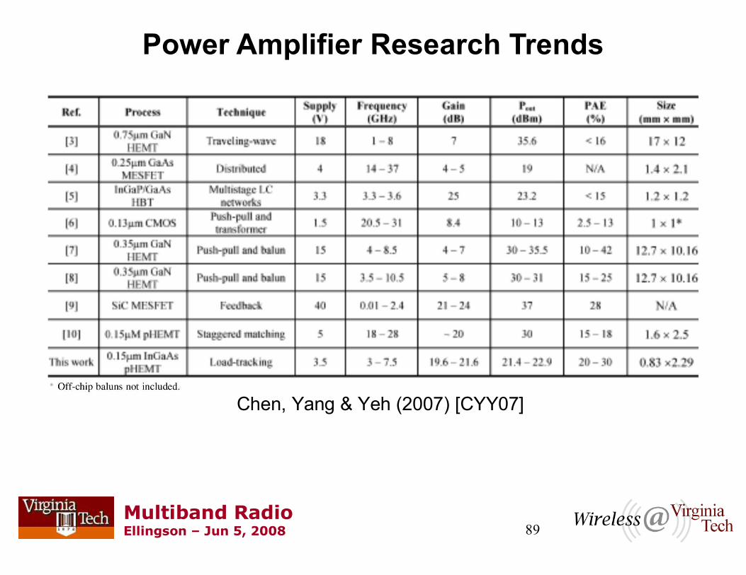
Power Amplifier Research Trends
Chen, Yang & Yeh (2007) [CYY07]

90Multiband RadioEllingson Jun 5, 2008
Outline of this Course
Introduction to Multiband/Multimode Radio (MMR)
Radio Design Basics
Antennas
Digitization
Sensitivity, Gain, and Noise
Linearity
Selectivity & Preselection
Conversion Architectures
RF CMOS
Antenna-Transceiver Interfacing
VT Public Safety MMR
Summary
Acknowledgements
References

91Multiband RadioEllingson Jun 5, 2008
Duplexers and Duplexing
A duplexer is a device which interfaces a receiver and transmitter in a to a common antenna, permitting either full or half duplex operation
Duplexer typically consist of combinations of (see subsequent slides)
Circulators
Diplexers (or triplexers, or multiplexers with any number of channels)
Switches (TDD or PTT protocols)Technologies: PIN diodes, GaAs, pHEMT, (emerging) MEMS

92Multiband RadioEllingson Jun 5, 2008
Circulator Duplexing
Ideal from the perspective of simultaneous T/R over multiple bands
In practice, an extreme challenge to prevent receiver desense and other isolation-related problems
Used to be that compact wideband circulators were not available, but are recently becoming plausible:
From [K05] From [EST06]

93Multiband RadioEllingson Jun 5, 2008
From [GB05]
Diplexer-based FEMs
Industry lingo:
FEM = Front End Module
Traditional (constant-impedance) diplexers
Because receivers and transmitters are always connected, TX->RX isolation is a concern.
Receiver desense is a common problem
Necessary filtering can become expensive or intractible

94Multiband RadioEllingson Jun 5, 2008
Lucero et al. (2001) [L+01]
Example: Dual-Band (Cellular/PCS) Front End
GSM (900 MHz) and DCS (1800 MHz) are implemented as mostly separate transceivers
GSM and DCS are TDD protocols. Therefore, simplest to implement T/R by switching
A diplexer interfaces the two independent bands to a single (presumably dual band) antenna

95Multiband RadioEllingson Jun 5, 2008
From [GB05]
Triplexer-based FEM
Same as previous slide, except now GPS is accomodated by changing diplexer to a triplexer
And you thought RX desense was a problem before...;)

96Multiband RadioEllingson Jun 5, 2008
Tang & You (2006) [TY06]
Example: Compact Nearly-Contiguous Triplexer
Contiguous bands are more challenging due to interactions between channels

97Multiband RadioEllingson Jun 5, 2008
The Classical PIN Diode T/R Switch
Diode changes states in response to applied DC bias voltage
Old school but still common due to it's simple broadband effectiveness.
As always, receive desense a concern
Virtually everything that improves densense or reduces size limits bandwidth
Many enhancements possible
From [K05]
Transmission line can bereplaced by discretesbelow ~500 MHz

98Multiband RadioEllingson Jun 5, 2008
From [GB05]
ASM-based FEMs
Industry lingo:
ASM = Antenna Switch Module
GSM (800 MHz), DCS (1800 MHz), and PCS (1900 MHz) are all essentially the same TDD protocol, implemented at different frequencies
TDD makes multibanding through a single antenna relatively simple, except for the obvious hassle of replicated electronics and finding a suitable (triband) antenna!

99Multiband RadioEllingson Jun 5, 2008
Antenna-Transceiver Interfacing
For multiband operation, options are limited!
Use multiple antennas
Use one or more multiband antennas
Broadband antenna with active tuning
Perhaps someday: Non-foster matching
For additional information and background on this general topic: [E07]

100Multiband RadioEllingson Jun 5, 2008
Antenna Tuning
Sense Match
Characteristics
TransceiverVariable
Reactor(s)
0RZA
0R

101Multiband RadioEllingson Jun 5, 2008
Variable Reactors [SS98]
Switching of fixed reactances in banks
Electromechanical RF switches
PIN diodes; other semiconductors
RF Microelectromechanical Switches (RF MEMS)
Electronically-variable reactances
Motor-driven geometry changers (inductors or capacitors)
Varactor diodes (Voltage-variable capacitance)

102Multiband RadioEllingson Jun 5, 2008
Compact Wideband Antenna Tuner
Uses four MPV1965 Varactor Diodes, 0.5-6 pF each
Significantly improves match over about a 20% bandwidth around the tuned frequency
Of course, match is worse everywhere else...tuners can only decrease BW.
Zhou & Melde (2007) [ZM07]

103Multiband RadioEllingson Jun 5, 2008
Someday: RF MEMS
From [R02]
Example: MEMS tunable filter [ER05]Example: MEMS reconfigurable antenna [A+06]Nevertheless, not quite ready ... [A07b]

104Multiband RadioEllingson Jun 5, 2008
Outline of this Course
Introduction to Multiband/Multimode Radio (MMR)
Radio Design Basics
Antennas
Digitization
Sensitivity, Gain, and Noise
Linearity
Selectivity & Preselection
Conversion Architectures
RF CMOS
Antenna-Transceiver Interfacing
VT Public Safety MMR
Summary
Acknowledgements
References

105Multiband RadioEllingson Jun 5, 2008
138-174 MHz 220-222 MHz406-512 MHz764-900 MHz
Motorola RFIC Ver. 4 [C+07]
4 MSPS baseband ADC/DAC
Baseband completely implemented in FPGA
Three board stack integrates antenna, RF Mux, transceiver RFIC, ADC / DAC,ref. freq. synthesizer
Altera EP2S60 FPGA Board
Touchscreen
Ethernet
Battery underneath
Audio I/F
Off-the-shelf antenna
Virginia Tech Public Safety MMR[VTMMR]

106Multiband RadioEllingson Jun 5, 2008
I.M
. M
UX
1 3 8 - 1 7 4
2 2 0 - 2 2 2
4 0 6 - 5 1 2
7 6 4 - 8 6 2
4 . 9 G H z D o w n
U H F
V H F
4 . 9 G H z U p
~ 1 0 d B
( B P F )
L O
S h o r tW h i p
E x t .A n t .
~ 3 0 d B
A / D
A / D
D / A
D / A
F P G A
P
em
ula
tio
n
E m b e d d e dA n t e n n a s
8 0 0 M H z / P C S C e l l u l a r C h i p s e t
2 . 4 G H z W L A N C e l l u l a r C h i p s e t
CO
DE
CO
the
r I/
O
To
uc
hs
cre
en
Kn
ob
s
P T T
S P K RM I C
VT Tranceiver Board usingMotorola Direct Conv. RFIC100-2500 MHz, 6.25 kHz 10 MHz BW
VT Antenna-Tranceiver I/FRF Multiplexer
Baseband ADC/DAC(4 MSPS x 14/10 b) +Ref. Freq. Synthesizer
Baseband processing uses SoPC-centric approach; Currently100% Verilog HDL
VT Public Safety MMR[VTMMR]

107Multiband RadioEllingson Jun 5, 2008
4-Band Transceiver Board 40 mA (RX) + 40-90 mA (TX) + 80 mA/DDS @ 9V< 25 cm2 to implement on a 4-layer PCBAbout $100 in parts to implement, excluding PCB.
TR#22 for Fall 2007 version
ADC / DAC / LO Synthesizer BoardADC/DAC: 130 mA @ 9V, running 4 MSPS< 50 cm2 to implement on a 4-layer PCB
ADC ~ $21 (1k), DAC ~ $10 (1k)
These two boards stack vertically with the RFFE board using MMCX connectors (no RF cables)
VT Public Safety MMR[VTMMR]

108Multiband RadioEllingson Jun 5, 2008
Meeting selectivity specs is one of the big challenges for this architecture
Our approach: RF multiplexer optimized to antenna impedance with external noise dominance constraint
No antenna tuning!
Simultaneous access to
multiple bands
Transducer power gain for RF multiplexer optimized for a 20 cm long monopole antenna
External noise dominance inVHF-High and 220 MHz bands
VT Public Safety MMR: Antenna IntegrationHasan & Ellingson (2008) [HE08]
(above results are simulations)

109Multiband RadioEllingson Jun 5, 2008
Outline of this Course
Introduction to Multiband/Multimode Radio (MMR)
Radio Design Basics
Antennas
Digitization
Sensitivity, Gain, and Noise
Linearity
Selectivity & Preselection
Conversion Architectures
RF CMOS
Antenna-Transceiver Interfacing
VT Public Safety MMR
Summary
Acknowledgements
References

110Multiband RadioEllingson Jun 5, 2008
Summary Remarks
MMR is enabling technology for military-type SDR and frequency-agile cognitive radio. It also has applications independently of these application areas: All-in-ones, public safety, ...
MMR has always been possible... but big, hot, and expensive
What is fueling progress & enthusiasm about MMR now is the prospect for achieving acceptable RF performance at much lower cost and power consumption. Key techologies:
Continued improvements in direct conversion and digital RF transceivers in CMOS
Antenna multibanding, physical integration, electrical integration (e.g., self-diplexing) and other forms of codesign
MEMS for reconfigurable antennas, matching circuits, and filters
There is still much to do. The next few years will be very interesting!

111Multiband RadioEllingson Jun 5, 2008
Acknowledgements
Students:
S.M. Shajedul Hasan
M. Harun
K.H. Lee
The author gratefully acknowledges the assistance and material support of Motorola Laboratories, Plantation, FL. Any opinions, findings, and conclusions or recommendations expressed in this material are those of the author(s) and do not necessarily reflect the views of the Motorola Corp.
This material is based upon work supported in part by the National Institute of Justice, U.S. Dept. of Justice, under Grant No. 2005-IJ-CX-K018. Any opinions, findings, and conclusions or recommendations expressed in this material are those of the author(s) and do not necessarily reflect the views of the U.S. Government.

112Multiband RadioEllingson Jun 5, 2008
References
[A03] A.A. Abidi, General Relations Between IP2, IP3, and Offsets in Differential Circuits and the Effects of Feedback, IEEE Trans. Microwave Theory & Techniques, Vol. 51, No. 5, May 2003, pp.1610-2.[A04] A.A. Abidi, RF CMOS Comes of Age, IEEE J. Solid-State Circuits, Vol. 39, No. 4, Apr 2004, pp. 549-61. [A07] A.A. Abidi, The Path to the Software-Defined Radio Receiver, IEEE J. Solid-State Circuits, Vol. 42, No. 5, May 2007, pp. 954-66.[A07b] R. Allan, Can RF MEMS Master the Mass-Market Challenge?, Electronic Design, April 2007, pp. 33-40.[AIO02] Adiseno, M. Ismail, and H. Olsson, A Wide-Band RF Front-End for Multiband Multistandard High-Linearity Low-IF Wireless Receivers, IEEE J. Solid-State Circuits, Vol. 37, No. 9, Sep 2002, pp. 1162-8.[A+99] D.M. Akos et al., Direct Bandpass Sampling of Multiple Distinct RF Signals, IEEE Trans. Communications, Vol. 47, No. 7, Jul 1999, pp. 983-8.[A+06] D.E. Anagnostou et al., Design, Fabrication, and Measurements of an RF MEMS-Based Self-Similar Reconfigurable Antenna, IEEE Trans. Ant. & Prop., Vol. 54, No. 4, Feb. 2006, pp. 422-32.[B03] P. Burns, Software Defined Radio for 3G, Artech House, 2003. [BBH00] E.E. Bautista, B. Bastani, and J. Heck,A High IIP2 Downconversion Mixer Using Dynamic Matching, IEEE J.
Solid State Circuits, Vol. 35, No. 12, Dec 2000, pp. 1934-1941.[C07] S. Cripps, The Intercept Point Deception, IEEE Microwave Mag., Feb 2007, pp. 44-50[CHE08] J. Craig, M. Harun, and S. Ellingson, On-the-Air Demonstration of a Prototype LWA Analog Signal Path, LWA Memo 130, Apr 2008. [online] http://www.phys.unm.edu/~lwa/memos [CYY07] Y.-J. E. Chen, L.-Y. Yang, and W.-C. Yeh, An Integrated Wideband Power Amplifier for Cognitive Radio, IEEE
Trans. Microwave Theory & Techniques, Vol. 55, No. 10, Oct 2007, pp. 2053-8.[C+05] C. Cho et al., IIP3 Estimation From the Gain Compression Curve, IEEE Trans. Microwave Theory &
Techniques, Vol. 53, No. 4, Apr 2005, pp. 1197-1202.[C+07] G. Cafero, A 100 MHz 2.5 Ghz Direct Conversion CMOS Transceiver for SDR Applications, 2007 IEEE RFIC
Symp., Jun 2007.[E01] S.W. Ellingson, "MRI Transceiver", U.S. Patent No. 6,259,253, July 2001.[E05a] S.W. Ellingson, "Antennas for the Next Generation of Low Frequency Radio Telescopes," IEEE Trans. Antennas and Propagation, Vol. 53, No. 8, August 2005, pp. 2480-9. [E05b] S.W. Ellingson, Spectral Occupancy at VHF: Implications for Frequency-Agile Cognitive Radios, IEEE Vehicular
Technology Conf., Vol. 2, Dallas TX, Sep 2005, pp. 1379-82.[E06] S.W. Ellingson, A Comparison of Some Existing Radios with Implications for Public Safety Interoperability, Virginia Tech Project Technical Report No. 4, Jun 2006. [on-line] http://www.ece.vt.edu/swe/chamrad.

113Multiband RadioEllingson Jun 5, 2008
References
[E07] S.W. Ellingson, Active Antennas (short course notes), 2007. Contact [email protected].[ER05] K. Entesari and G.M. Rebeiz, A Differential 4-bit 6.5-10 Ghz RF MEMS Tunable Filter, IEEE Trans. IEEE Microwave
Theory & Techniques, Vol. 53, No. 3, March 2005, pp. 1103-1110. [EST06] W.R. Eisenstadt, B. Stengle, B.M. Thompson, Microwave Differential Circuit Design using Mixed-Mode S-
Parameters, Artech House, 2006.[ET96] C.C. Enz and G.C. Temes, Circuit Techniques for Reducing the Effects of Op-Amp Imperfections: Autozeroing, Correlated Double Sampling, and Chopper Stabilization, Proc. IEEE, Vol. 84, No. 11, Nov 1996, pp. 1584-1614.[F+07] A. Faraone et al., Enabling Antenna Technologies for the Software Definable Radio, 2nd European Conf. Ant. & Prop.
(EuCAP2007), Nov 2007, pp. 1-6. [GB05] W.-C. A. Gu and B. Balut, Integration of Cellular Handset RF Front-End Modules, Microwave Product Digest, June 2005.[GF08] B. Godara and A. Fabre, A Highly Compact Active Wideband Balun With Impedance Transformation in SiGe BiCMOS, IEEE Trans. Microwave Theory and Techniques, Vol. 56, No. 1, Jan 2008, pp. 22-30.[GPO08] A. Gimeno-Martin, J.M. Pardo-Martin, and F.J. Ortega-Gonzalez, Adaptive Algorithm for Increasing Image Rejection Ratio in Low-IF Receivers, Electronics Letters, Vol. 44, No. 6, Mar 2008.[G+08] C.J. Galbraith et al., Cochlea-Based RF Channelizing Filters, IEEE Trans. Circuits & Systems I, Vol. 55, No. 4, May 2008, pp. 969-79.[H05] T. Hentshel, The Six-Port as a Communications Receiver, IEEE Trans. Microwave Theory & Techniques, Vol. 53, No. 3, Mar 2005, pp. 1039-1047.[HH02] H. Hashemi and A. Hajimiri, Concurrent Multiband Low-Noise Amplifiers Theory, Design, and Applications, IEEE
Journal of Solid-State Circuits, vol. 50, no. 1, Jan 2002, pp. 288-301.[HE06] S.M.S. Hasan & S.W. Ellingson, A Wideband RF Downconverter for the NIJ Public Safety Radio, Virginia Tech Project Technical Report No. 16, Dec 2006. [on-line] http://www.ece.vt.edu/swe/chamrad. [HE08] S.M.S. Hasan & S.W. Ellingson, Multiband Antenna-Receiver Integration using an RF Multiplexer with Sensitivity-Constrained Design, IEEE Int'l Symp. Ant. & Prop., San Diego, CA, July 2008. (Preprint available: see [VTMMR])[H+07] I. Hunter, Microwave Filter Design from a Systems Perspective, IEEE Microwave Mag., Oct 2007, pp. 71-7.[ITU03] ITU-R: Radio Noise, Rec. P.372-8, 2003. [J08] D. Jackson, A Corner Turned, MRT (magazine), May 2008, pp. 36-41.[K05] P.B. Kenington, RF and Baseband Techniques for Software Defined Radio, Artech House, 2005.

114Multiband RadioEllingson Jun 5, 2008
References
[[KA00] P.B. Kenington and L. Astier, Power Consumption of A/D Converters for Software Radio Applications, IEEE Trans.
Vehicular Technology, Vol. 49, No. 2, Mar 2000, pp. 643-50.[HC85] B.C. Henderson and J.A. Cook, Image-Reject and Single-Sideband Mixers, Watkins-Johnson Co. Tech-note, Vol. 12, No. 3, May/Jun 1985.[ITU03] ITU-R: Radio Noise, Rec. P.372-8, 2003. [J08] D. Jackson, A Corner Turned, MRT (magazine), May 2008, pp. 36-41.[K05] P.B. Kenington, RF and Baseband Techniques for Software Defined Radio, Artech House, 2005.[KA00] P.B. Kenington and L. Astier, Power Consumption of A/D Converters for Software Radio Applications, IEEE Trans.
Vehicular Technology, Vol. 49, No. 2, Mar 2000, pp. 643-50.[HC85] B.C. Henderson and J.A. Cook, Image-Reject and Single-Sideband Mixers, Watkins-Johnson Co. Tech-note, Vol. 12, No. 3, May/Jun 1985.[L04] T.H. Lee, The Design of CMOS Radio-Frequency Integrated Circuits, 2nd Ed., Cambridge University Press, 2004.[LA02] A. Loke and F. Ali, Direct Conversion Radio for Digital Mobile Phones Design Issues, Status, and Trends, IEEE
Trans. Microwave Theory & Techniques, Vol. 50, No. 11, Nov 2002, pp. 2422-2435. [LD07] L. Luu and B. Deneshrad, An Adaptive Weaver Architecture Radio with Spectrum Sensing Capabilities to Relax RF Component Requirements, IEEE J. Selected Areas in Communications, Vol. 25, No. 3, Apr 2007, pp.538-45.[L+01] R. Lucero et al., Design of an LTCC Switch Diplexer Front-End Module for GSM/DCS/PCS Applications, IEEE Radio
Frequency Integrated Circuits Sym., 2001, pp. 213-6.[MSL05] K. Muhammad, R.B. Staszewski, and D. Leipold, Digital RF Processing: Toward Low-Cost Reconfigurable Radios, IEEE Communications Magazine, Aug 2005, pp. 105-113.[MYJ80] G. Matthaei, L. Young, E.M.T. Jones, Microwave Filters, Impedance-Matching Networks, and Coupling Structures, Artech House, 1980.[O05] S. Ooi, Wideband Monopole Antenna for Public Safety Radio, IEEE Int'l Symp. Ant. & Prop., Vol. 2A, Jul 2005, pp. 363-6.

115Multiband RadioEllingson Jun 5, 2008
References
[PR08] S.-J. Park and G.M. Rebeiz, Low-Loss Two-Pole Tunable Filters With Three Different Predefined Bandwidth Characteristics, IEEE Trans. Microwave Theory & Techniques, Vol. 56, No. 5, May 2008, pp. 1137-48.[PS07] R. Paulsen and M. Spencer, Miniaturization of Fixed and Tunable Filters Where and When to Use Integrated Passive Devices, SDR Forum Technical Conf., 2007.[P+08] B.G. Perumana et al., Resistive-Feedback CMOS Low-Noise Amplifiers for Multiband Applications, IEEE Trans.
Microwave Theory and Techniques, Vol. 56, No. 5, May 2008, pp. 1218-25.[R02] J.H. Reed, Software Radio: A Modern Approach to Radio Engineering, Prentice-Hall, 2002.[R97] B. Razavi, Design Considerations for Direct-Conversion Receivers, IEEE Trans. Circuits & Systems II, Vol. 44, No. 6, Jun 1997, pp. 428-435.[R98] B. Razavi, RF Microelectronics, Prentice-Hall, 1998.[RE02] E. Ranu and S.W. Ellingson, A Low-Cost Wideband UHF Downconverter with 5:1 Tuning Range", IEEE Trans.
Instrumentation & Measurement, Vol. 51, No. 5, Oct 2002, pp. 1080-1084. [R+98] A. Rofougaran et al., A Single-Chip 900-MHz Spread-Spectrum Wireless Transceiver in 1-mm CMOS Part I: Architecture and Transmitter Design, IEEE J. Solid State Circuits, Vol. 33, No. 4, Apr 1998, pp. 515-34.[S99] W.E. Sabin, Diplexer Filters for an HF MOSFET Power Amplifier, QEX, Jul/Aug 1999, pp. 20-6.[SS98] W.E. Sabin & E.O. Schoenicke (eds.), HF Radio Systems & Circuits, Rev. 2nd ed., Noble, 1998.[TY06] C.-W. Tang and S.-F. You, Design Methodologies of LTCC Bandpass Filters, Diplexer, and Triplexer with Transmission Zeros, IEEE Trans. Microwave Theory & Techniques, Vol. 54, No. 2, Feb 2006, pp. 717-23.[T+07] A. Tasic et al., Design of Adaptive Multimode RF Front End Circuits, IEEE J. Solid-State Circuits, Vol. 42, No. 2, Feb 2007, pp. 313-322. [VTMMR] Virginia Tech, Multiband / Multimode Radio for Public Safety Applications, Project web site [on-line] http://www.ece.vt.edu/swe/chamrad/.[WM07] K.-L. Wu and W. Meng, A Direct Synthesis Approach for Microwave Filters With a Complex Load and Its Application to Direct Diplexer Design, IEEE Trans. Microwave Theory & Techniques, Vol. 55, No. 5, May 2007, pp. 1010-7.[ZM07] Z. Zhou and K.L. Melde, Frequency Agility of Broadband Antennas Integrated with a Reconfigurable RF Impedance Tuner, IEEE Ant. & Wireless Prop. Let., Vol. 6, 2007, pp. 56-59.
Related Documents