Design, Simulation and Implementation of a Channel Equalizer for DVB-T On-Channel Repeaters Mikel Mendicute, Iker Sobr´ on, Javier Del Ser Signal Theory and Communications Area University of Mondrag´ on Loramendi, 4, 20500 Mondrag ´ on, Spain Contact e-mail: [email protected] Pablo Prieto Telecommunications Area Robotiker-Tecnalia Parque Tecnol´ ogico, 202 48170 Zamudio, Spain e-mail: [email protected] Ricardo Isasi Signal Processing Division Fagor Electr´ onica S. Coop. San Andr´ es, s/n, 20500 Mondrag ´ on, Spain e-mail: [email protected] Abstract This article describes the design and implementation of a channel equalizer for a terrestrial digital television (Dig- ital Video Broadcasting-Terrestrial, DVB-T) on-channel re- peater, namely gap-filler. Two are the benefits of including this equalizer in a repeater setup: on one hand, the trans- mitted signal requires a lower dynamic range and its degra- dation becomes smaller at the output amplifiers, thus allow- ing for a higher transmit power for the same modulation error rate (MER). On the other hand, it eases the equaliza- tion and decoding processes at the final receiver by improv- ing its operation conditions. In this context, we present a novel low-cost equalizer architecture for mid-range and do- mestic gap-fillers. The design, implementation and valida- tion methodology is also described, from the initial Matlab and Advanced Design System (ADS) simulations to the final hardware implementation, based on a field programmable gate array (FPGA) device and a Blackfin digital signal pro- cessor (DSP). The obtained practical results assess the per- formance gains predicted by simulation, hence proving the validity and efficacy of the designed equalizer to reduce the cost of the amplifiers and to obtain a better signal quality at the final user’s receiver. 1 Introduction On-channel repeaters or gap-fillers are systems that re- transmit the digital television signal in order to improve coverage and quality of service in shadowed areas, which cannot be reached by the source transmitters [1, 2]. If a single frequency network (SFN) is deployed, which is the case for DVB-T broadcasting in several countries, these gap-fillers must be able to retransmit the signal, using or- thogonal frequency division multiplexing (OFDM), with a delay shorter than the guard interval (GI) [3]. Due to this requirement and the reduced target costs often imposed by development companies, a domestic gap-filler is usually im- plemented as an analog device whose simplified structure is shown in Figure 1. As shown, the equipment performs a downconversion of the input radio frequency (RF) signal to intermediate frequency (IF), filters the resulting signal and converts it back to RF, where it is amplified before retrans- mission. Figure 1. Structure of a common domestic analog DVB-T gap-filler. As previously stated, the DVB-T standard [3] includes OFDM, whose main drawback is basically its large peak- to-average power ratio (PAPR) that determines the dynamic range of the transmit amplifiers and, therefore, the cost of the product for a target output power. The required dynamic range of the amplifiers can become even more demanding if the spectrum of the transmitted signal is not flat. This is the case of a common gap-filler, where the spectrum of the input signal has been shaped by the outdoor channel, located between the original transmitter and the reception antenna of the gap-filler. Several equalization approaches have been reported in the literature [4, 5], mainly focused on expensive high-performance professional repeaters. This article describes the design, simulation and imple- The Third International Conference on Systems and Networks Communications 978-0-7695-3371-1/08 $25.00 © 2008 IEEE DOI 10.1109/ICSNC.2008.13 11 The Third International Conference on Systems and Networks Communications 978-0-7695-3371-1/08 $25.00 © 2008 IEEE DOI 10.1109/ICSNC.2008.13 11

Welcome message from author
This document is posted to help you gain knowledge. Please leave a comment to let me know what you think about it! Share it to your friends and learn new things together.
Transcript
Design, Simulation and Implementation of a Channel Equalizer for DVB-TOn-Channel Repeaters
Mikel Mendicute, Iker Sobron, Javier Del Ser
Signal Theory and Communications Area
University of Mondragon
Loramendi, 4,
20500 Mondragon, Spain
Contact e-mail: [email protected]
Pablo Prieto
Telecommunications Area
Robotiker-Tecnalia
Parque Tecnologico, 202
48170 Zamudio, Spain
e-mail: [email protected]
Ricardo Isasi
Signal Processing Division
Fagor Electronica S. Coop.
San Andres, s/n,
20500 Mondragon, Spain
e-mail: [email protected]
Abstract
This article describes the design and implementation ofa channel equalizer for a terrestrial digital television (Dig-ital Video Broadcasting-Terrestrial, DVB-T) on-channel re-peater, namely gap-filler. Two are the benefits of includingthis equalizer in a repeater setup: on one hand, the trans-mitted signal requires a lower dynamic range and its degra-dation becomes smaller at the output amplifiers, thus allow-ing for a higher transmit power for the same modulationerror rate (MER). On the other hand, it eases the equaliza-tion and decoding processes at the final receiver by improv-ing its operation conditions. In this context, we present anovel low-cost equalizer architecture for mid-range and do-mestic gap-fillers. The design, implementation and valida-tion methodology is also described, from the initial Matlaband Advanced Design System (ADS) simulations to the finalhardware implementation, based on a field programmablegate array (FPGA) device and a Blackfin digital signal pro-cessor (DSP). The obtained practical results assess the per-formance gains predicted by simulation, hence proving thevalidity and efficacy of the designed equalizer to reduce thecost of the amplifiers and to obtain a better signal quality atthe final user’s receiver.
1 Introduction
On-channel repeaters or gap-fillers are systems that re-transmit the digital television signal in order to improvecoverage and quality of service in shadowed areas, whichcannot be reached by the source transmitters [1, 2]. If asingle frequency network (SFN) is deployed, which is thecase for DVB-T broadcasting in several countries, thesegap-fillers must be able to retransmit the signal, using or-
thogonal frequency division multiplexing (OFDM), with adelay shorter than the guard interval (GI) [3]. Due to thisrequirement and the reduced target costs often imposed bydevelopment companies, a domestic gap-filler is usually im-plemented as an analog device whose simplified structure isshown in Figure 1. As shown, the equipment performs adownconversion of the input radio frequency (RF) signal tointermediate frequency (IF), filters the resulting signal andconverts it back to RF, where it is amplified before retrans-mission.
Figure 1. Structure of a common domesticanalog DVB-T gap-filler.
As previously stated, the DVB-T standard [3] includesOFDM, whose main drawback is basically its large peak-to-average power ratio (PAPR) that determines the dynamicrange of the transmit amplifiers and, therefore, the cost ofthe product for a target output power. The required dynamicrange of the amplifiers can become even more demandingif the spectrum of the transmitted signal is not flat. Thisis the case of a common gap-filler, where the spectrum ofthe input signal has been shaped by the outdoor channel,located between the original transmitter and the receptionantenna of the gap-filler. Several equalization approacheshave been reported in the literature [4, 5], mainly focusedon expensive high-performance professional repeaters.
This article describes the design, simulation and imple-
The Third International Conference on Systems and Networks Communications
978-0-7695-3371-1/08 $25.00 © 2008 IEEE
DOI 10.1109/ICSNC.2008.13
11
The Third International Conference on Systems and Networks Communications
978-0-7695-3371-1/08 $25.00 © 2008 IEEE
DOI 10.1109/ICSNC.2008.13
11
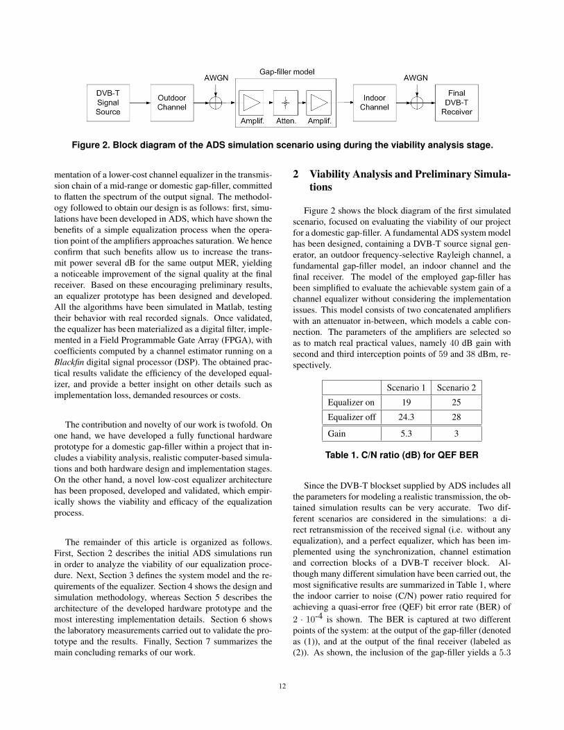
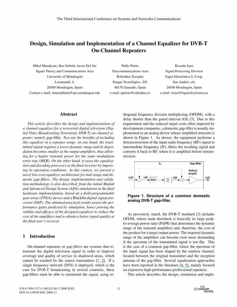
Figure 2. Block diagram of the ADS simulation scenario using during the viability analysis stage.
mentation of a lower-cost channel equalizer in the transmis-sion chain of a mid-range or domestic gap-filler, committedto flatten the spectrum of the output signal. The methodol-ogy followed to obtain our design is as follows: first, simu-lations have been developed in ADS, which have shown thebenefits of a simple equalization process when the opera-tion point of the amplifiers approaches saturation. We henceconfirm that such benefits allow us to increase the trans-mit power several dB for the same output MER, yieldinga noticeable improvement of the signal quality at the finalreceiver. Based on these encouraging preliminary results,an equalizer prototype has been designed and developed.All the algorithms have been simulated in Matlab, testingtheir behavior with real recorded signals. Once validated,the equalizer has been materialized as a digital filter, imple-mented in a Field Programmable Gate Array (FPGA), withcoefficients computed by a channel estimator running on aBlackfin digital signal processor (DSP). The obtained prac-tical results validate the efficiency of the developed equal-izer, and provide a better insight on other details such asimplementation loss, demanded resources or costs.
The contribution and novelty of our work is twofold. Onone hand, we have developed a fully functional hardwareprototype for a domestic gap-filler within a project that in-cludes a viability analysis, realistic computer-based simula-tions and both hardware design and implementation stages.On the other hand, a novel low-cost equalizer architecturehas been proposed, developed and validated, which empir-ically shows the viability and efficacy of the equalizationprocess.
The remainder of this article is organized as follows.First, Section 2 describes the initial ADS simulations runin order to analyze the viability of our equalization proce-dure. Next, Section 3 defines the system model and the re-quirements of the equalizer. Section 4 shows the design andsimulation methodology, whereas Section 5 describes thearchitecture of the developed hardware prototype and themost interesting implementation details. Section 6 showsthe laboratory measurements carried out to validate the pro-totype and the results. Finally, Section 7 summarizes themain concluding remarks of our work.
2 Viability Analysis and Preliminary Simula-tions
Figure 2 shows the block diagram of the first simulatedscenario, focused on evaluating the viability of our projectfor a domestic gap-filler. A fundamental ADS system modelhas been designed, containing a DVB-T source signal gen-erator, an outdoor frequency-selective Rayleigh channel, afundamental gap-filler model, an indoor channel and thefinal receiver. The model of the employed gap-filler hasbeen simplified to evaluate the achievable system gain of achannel equalizer without considering the implementationissues. This model consists of two concatenated amplifierswith an attenuator in-between, which models a cable con-nection. The parameters of the amplifiers are selected soas to match real practical values, namely 40 dB gain withsecond and third interception points of 59 and 38 dBm, re-spectively.
Scenario 1 Scenario 2
Equalizer on 19 25
Equalizer off 24.3 28
Gain 5.3 3
Table 1. C/N ratio (dB) for QEF BER
Since the DVB-T blockset supplied by ADS includes allthe parameters for modeling a realistic transmission, the ob-tained simulation results can be very accurate. Two dif-ferent scenarios are considered in the simulations: a di-rect retransmission of the received signal (i.e. without anyequalization), and a perfect equalizer, which has been im-plemented using the synchronization, channel estimationand correction blocks of a DVB-T receiver block. Al-though many different simulation have been carried out, themost significative results are summarized in Table 1, wherethe indoor carrier to noise (C/N) power ratio required forachieving a quasi-error free (QEF) bit error rate (BER) of2 · 10-4 is shown. The BER is captured at two differentpoints of the system: at the output of the gap-filler (denotedas (1)), and at the output of the final receiver (labeled as(2)). As shown, the inclusion of the gap-filler yields a 5.3
1212
dB gain at the output of the gap-filler, and degrades down to3 dB when an indoor channel is added to the system.
3 System Model and Parameters
Figure 3 depicts a simplified diagram of the system underconsideration. The RF signal sR(t) is generated and trans-mitted at the source, distorted by the outdoor channel hR
and received at the gap-filler. The signal is then downcon-verted to IF (r′I(t)) and normalized by an automatic gaincontrol (AGC), leading to rI(t), which is the input of theequalizer described in this article. An analog to digital con-verter (ADC) samples the IF input signal at a sample rateFs, resulting in rI(k).
The equalizer processes the input signal in two differ-ent manners. On one hand, it is filtered by a digital finiteimpulse response filter (FIR), which aims at flattening thespectrum of the signal at the band of interest. On the otherhand, the input signal rI(k) is also processed by a chan-nel estimator block, which computes the coefficients of theaforementioned FIR filter. As shown in Figure 3, the outputof the filter, denoted as tI(k), is input to a digital-to-analogconverter (DAC), resulting in tI(t) which is then filtered,upconverted, amplified and retransmitted.
The main parameters of the system depend on two fac-tors: the IF frequency of the gapfiller devices which is set1
to 36.125 MHz; and the particular characteristics of theDVB-T deployment in Spain, which can be summarized as8192 (8K) subcarriers, among which 6715 are used, 1/4 ofguard interval, 64-QAM constellation and a convolutionalcoding rate of 2/3 [3]. Regarding channel estimation, DVB-T defines two types of pilot symbols: continual, which areavailable in all the symbols, and scattered, which may be-long to 4 different sets of subcarriers.
As stated before, the equalizer works with the IF signal,sampled at a rate of Fs. Therefore, an equivalent systemmodel is needed according to these parameters. The rela-tionship between the originally transmitted DVB-T and re-ceived signals can be represented in IF as
rI(k) =L−1∑τ=0
sI(k − τ)hI(τ) + nI(k), (1)
where sI(k) and rI(k) stand for the transmitted and re-ceived IF signals, respectively, while nI(k) is the additivewhite Gaussian noise (AWGN). The term hI(τ) representsthe channel impulse response at the delay τ , which can havea value in the range [0 ... L− 1]. The effect of the equaliza-tion filter, the C coefficients of which are denoted as c(τ),
1Typical specifications established by Fagor Electronica, a Spanishmanufacturer of DVB-T gap-filler and receivers.
can be also modeled as
tI(k) =C−1∑τ=0
rI(k − τ)c(τ). (2)
The combination of Equations 1 and 2 can be representedin the frequency domain by the following equation:
TI(f) = C(f)HI(f)SI(f) + C(f)NI(f), (3)
where C(f), HI(f) y SI(f) are the filter response, thechannel gain and the value of the original signal for fre-quency f . Therefore, the objective is to design an FIR fil-ter with a frequency response that inverts the effect of thechannel for the frequency band of interest. Although otheralternatives exist, such as the minimum mean squared er-ror (MMSE) based equalization, a pure inversion or zero-forcing (ZF) algorithm has been chosen for its simplicity,which can be expressed as:
C(f) =1
HI(f). (4)
The complete frequency response of the channel, repre-sented by vector HI , is then required for Equation 4 andmust be estimated from the channel gains at the pilot sub-carriers provided by the DVB-T standard [3], representedby the vector Hsp. The channel estimator must then calcu-late the value of Hsp, interpolate the values for the rest ofsubcarriers and calculate the frequency response of the fil-ter. Last, the coefficients of the FIR filter must be chosen soas to meet the desired frequency response with a samplingfrequency of Fs.
A sampling frequency of Fs = 21 MHz has been chosen,which subsamples the IF signal, translating the 7.6 MHz ofuseful bandwidth from 36.125 MHz to 5.875 MHz. It alsoallows for enough resolution and processing speed for thefilter. Therefore, the channel estimator must generate thecoefficients of the filter, which runs at a frequency of 21Mhz, parting from the channel estimate obtained using thepilot subcarriers, which are transmitted with a symbol fre-quency of 64/7 = 9.14 MHz, so as the rest of the basebandDVB-T symbols.
Thanks to OFDM, the channel estimation is a relativelysimple task for each pilot subcarrier. Once the receivedsignal has been properly synchronized, the relationship be-tween the input and output signals at the p-th subcarrier canbe easily represented as
R(p) = S(p)H(p) + N(p), 1 ≤ p ≤ 6817, (5)
where S(p), R(p) and N(p) are the transmitted sym-bol, the received symbol and the noise value at the p-th subcarrier, respectively, while H(p) is the channel re-sponse. The channel estimate H(p) can then be calculated
1313
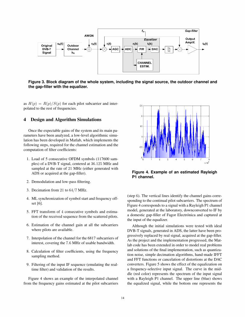
Figure 3. Block diagram of the whole system, including the signal source, the outdoor channel andthe gap-filler with the equalizer.
as H(p) = R(p)/S(p) for each pilot subcarrier and inter-polated to the rest of frequencies.
4 Design and Algorithm Simulations
Once the expectable gains of the system and its main pa-rameters have been analyzed, a low-level algorithmic simu-lation has been developed in Matlab, which implements thefollowing steps, required for the channel estimation and thecomputation of filter coefficients:
1. Load of 5 consecutive OFDM symbols (117600 sam-ples) of a DVB-T signal, centered at 36.125 MHz andsampled at the rate of 21 MHz (either generated withADS or acquired at the gap-filler).
2. Demodulation and low-pass filtering.
3. Decimation from 21 to 64/7 MHz.
4. ML synchronization of symbol start and frequency off-set [6].
5. FFT transform of 4 consecutive symbols and estima-tion of the received sequence from the scattered pilots.
6. Estimation of the channel gain at all the subcarrierswhere pilots are available.
7. Interpolation of the channel for the 6817 subcarriers ofinterest, covering the 7.6 MHz of usable bandwidth.
8. Calculation of filter coefficients, using the frequencysampling method.
9. Filtering of the input IF sequence (emulating the real-time filter) and validation of the results.
Figure 4 shows an example of the interpolated channelfrom the frequency gains estimated at the pilot subcarriers
Figure 4. Example of an estimated RayleighP1 channel.
(step 6). The vertical lines identify the channel gains corre-sponding to the continual pilot subcarriers. The spectrum ofFigure 4 corresponds to a signal with a Rayleigh P1 channelmodel, generated at the laboratory, downconverted to IF bya domestic gap-filler of Fagor Electronica and captured atthe input of the equalizer.
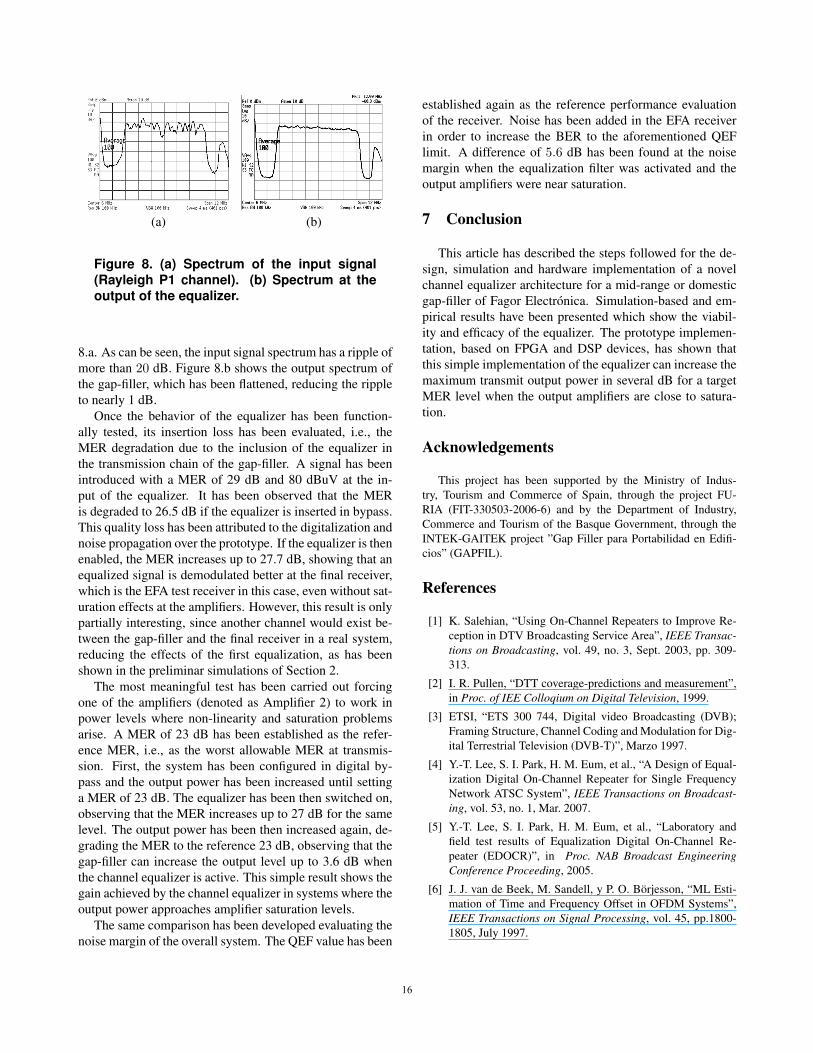
Although the initial simulations were tested with idealDVB-T signals, generated in ADS, the latter have been pro-gressively replaced by real signal, acquired at the gap-filler.As the project and the implementation progressed, the Mat-lab code has been extended in order to model real problemsand solutions of the final implementation, such as quantiza-tion noise, simple decimation algorithms, hand-made IFFTand FFT functions or cancelation of distortions at the DACconverters. Figure 5 shows the effect of the equalization ona frequency-selective input signal. The curve in the mid-dle (red color) represents the spectrum of the input signalwith a Rayleigh P1 channel. The upper line (blue) showsthe equalized signal, while the bottom one represents the
1414
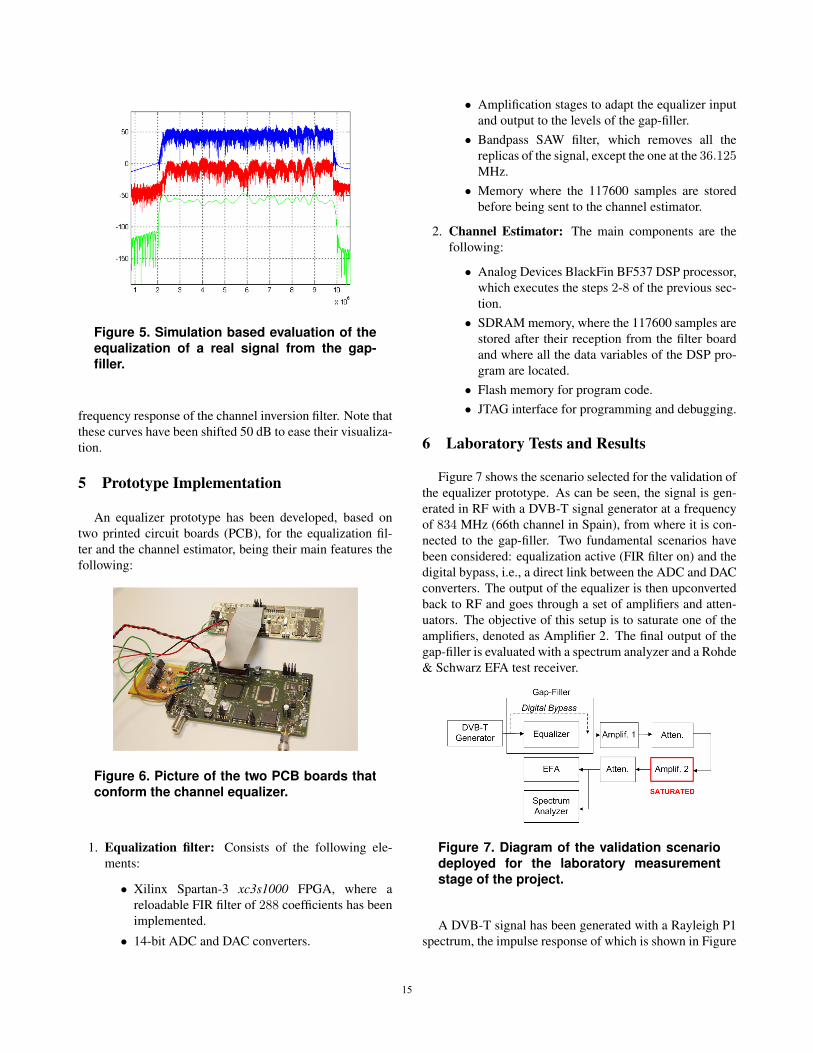
Figure 5. Simulation based evaluation of theequalization of a real signal from the gap-filler.
frequency response of the channel inversion filter. Note thatthese curves have been shifted 50 dB to ease their visualiza-tion.
5 Prototype Implementation
An equalizer prototype has been developed, based ontwo printed circuit boards (PCB), for the equalization fil-ter and the channel estimator, being their main features thefollowing:
Figure 6. Picture of the two PCB boards thatconform the channel equalizer.
1. Equalization filter: Consists of the following ele-ments:
• Xilinx Spartan-3 xc3s1000 FPGA, where areloadable FIR filter of 288 coefficients has beenimplemented.
• 14-bit ADC and DAC converters.
• Amplification stages to adapt the equalizer inputand output to the levels of the gap-filler.
• Bandpass SAW filter, which removes all thereplicas of the signal, except the one at the 36.125MHz.
• Memory where the 117600 samples are storedbefore being sent to the channel estimator.
2. Channel Estimator: The main components are thefollowing:
• Analog Devices BlackFin BF537 DSP processor,which executes the steps 2-8 of the previous sec-tion.
• SDRAM memory, where the 117600 samples arestored after their reception from the filter boardand where all the data variables of the DSP pro-gram are located.
• Flash memory for program code.• JTAG interface for programming and debugging.
6 Laboratory Tests and Results
Figure 7 shows the scenario selected for the validation ofthe equalizer prototype. As can be seen, the signal is gen-erated in RF with a DVB-T signal generator at a frequencyof 834 MHz (66th channel in Spain), from where it is con-nected to the gap-filler. Two fundamental scenarios havebeen considered: equalization active (FIR filter on) and thedigital bypass, i.e., a direct link between the ADC and DACconverters. The output of the equalizer is then upconvertedback to RF and goes through a set of amplifiers and atten-uators. The objective of this setup is to saturate one of theamplifiers, denoted as Amplifier 2. The final output of thegap-filler is evaluated with a spectrum analyzer and a Rohde& Schwarz EFA test receiver.
Figure 7. Diagram of the validation scenariodeployed for the laboratory measurementstage of the project.
A DVB-T signal has been generated with a Rayleigh P1spectrum, the impulse response of which is shown in Figure
1515
(a) (b)
Figure 8. (a) Spectrum of the input signal(Rayleigh P1 channel). (b) Spectrum at theoutput of the equalizer.
8.a. As can be seen, the input signal spectrum has a ripple ofmore than 20 dB. Figure 8.b shows the output spectrum ofthe gap-filler, which has been flattened, reducing the rippleto nearly 1 dB.
Once the behavior of the equalizer has been function-ally tested, its insertion loss has been evaluated, i.e., theMER degradation due to the inclusion of the equalizer inthe transmission chain of the gap-filler. A signal has beenintroduced with a MER of 29 dB and 80 dBuV at the in-put of the equalizer. It has been observed that the MERis degraded to 26.5 dB if the equalizer is inserted in bypass.This quality loss has been attributed to the digitalization andnoise propagation over the prototype. If the equalizer is thenenabled, the MER increases up to 27.7 dB, showing that anequalized signal is demodulated better at the final receiver,which is the EFA test receiver in this case, even without sat-uration effects at the amplifiers. However, this result is onlypartially interesting, since another channel would exist be-tween the gap-filler and the final receiver in a real system,reducing the effects of the first equalization, as has beenshown in the preliminar simulations of Section 2.
The most meaningful test has been carried out forcingone of the amplifiers (denoted as Amplifier 2) to work inpower levels where non-linearity and saturation problemsarise. A MER of 23 dB has been established as the refer-ence MER, i.e., as the worst allowable MER at transmis-sion. First, the system has been configured in digital by-pass and the output power has been increased until settinga MER of 23 dB. The equalizer has been then switched on,observing that the MER increases up to 27 dB for the samelevel. The output power has been then increased again, de-grading the MER to the reference 23 dB, observing that thegap-filler can increase the output level up to 3.6 dB whenthe channel equalizer is active. This simple result shows thegain achieved by the channel equalizer in systems where theoutput power approaches amplifier saturation levels.
The same comparison has been developed evaluating thenoise margin of the overall system. The QEF value has been
established again as the reference performance evaluationof the receiver. Noise has been added in the EFA receiverin order to increase the BER to the aforementioned QEFlimit. A difference of 5.6 dB has been found at the noisemargin when the equalization filter was activated and theoutput amplifiers were near saturation.
7 Conclusion
This article has described the steps followed for the de-sign, simulation and hardware implementation of a novelchannel equalizer architecture for a mid-range or domesticgap-filler of Fagor Electronica. Simulation-based and em-pirical results have been presented which show the viabil-ity and efficacy of the equalizer. The prototype implemen-tation, based on FPGA and DSP devices, has shown thatthis simple implementation of the equalizer can increase themaximum transmit output power in several dB for a targetMER level when the output amplifiers are close to satura-tion.
Acknowledgements
This project has been supported by the Ministry of Indus-try, Tourism and Commerce of Spain, through the project FU-RIA (FIT-330503-2006-6) and by the Department of Industry,Commerce and Tourism of the Basque Government, through theINTEK-GAITEK project ”Gap Filler para Portabilidad en Edifi-cios” (GAPFIL).
References
[1] K. Salehian, “Using On-Channel Repeaters to Improve Re-ception in DTV Broadcasting Service Area”, IEEE Transac-tions on Broadcasting, vol. 49, no. 3, Sept. 2003, pp. 309-313.
[2] I. R. Pullen, “DTT coverage-predictions and measurement”,in Proc. of IEE Colloqium on Digital Television, 1999.
[3] ETSI, “ETS 300 744, Digital video Broadcasting (DVB);Framing Structure, Channel Coding and Modulation for Dig-ital Terrestrial Television (DVB-T)”, Marzo 1997.
[4] Y.-T. Lee, S. I. Park, H. M. Eum, et al., “A Design of Equal-ization Digital On-Channel Repeater for Single FrequencyNetwork ATSC System”, IEEE Transactions on Broadcast-ing, vol. 53, no. 1, Mar. 2007.
[5] Y.-T. Lee, S. I. Park, H. M. Eum, et al., “Laboratory andfield test results of Equalization Digital On-Channel Re-peater (EDOCR)”, in Proc. NAB Broadcast EngineeringConference Proceeding, 2005.
[6] J. J. van de Beek, M. Sandell, y P. O. Borjesson, “ML Esti-mation of Time and Frequency Offset in OFDM Systems”,IEEE Transactions on Signal Processing, vol. 45, pp.1800-1805, July 1997.
1616
Related Documents