Design Report -Ryerson Supermileage Team- Prepared for the Society of Automotive Engineers (SAE) for the 2010 Supermileage Competition Written by: Charles Wong & Ivan Monroy Ortiz

Welcome message from author
This document is posted to help you gain knowledge. Please leave a comment to let me know what you think about it! Share it to your friends and learn new things together.
Transcript

Design Report -Ryerson Supermileage Team-
Prepared for the Society of Automotive Engineers (SAE)
for the 2010 Supermileage Competition
Written by: Charles Wong & Ivan Monroy Ortiz

P a g e | 1
Table of Contents
1 Basic Vehicle Configuration ................................................................................................................. 2
1.1 Vehicle Dimensions (Units in Meters) ..................................................................................... 4
1.2 General Dimensions and Technical Specifications ................................................................... 6
1.3 Location of Components ........................................................................................................ 6
1.3.1 Location of Components in Vehicle ............................................................................ 7
1.4 Chassis Modifications ............................................................................................................. 7
2 Engine .............................................................................................................................................. 10
3 Powertrain Configuration.................................................................................................................. 14
4 Brake System .................................................................................................................................... 17
5 Suspension and Running Gear ........................................................................................................... 19
6 Body/ Aerodynamic Shell .................................................................................................................. 24
7 Performance ..................................................................................................................................... 35
8 Cost Estimate and Manufacturing Methods ...................................................................................... 36
9 Driver Safety Features ...................................................................................................................... 40
10 Appendix .......................................................................................................................................... 43

P a g e | 2
1 Basic Vehicle Configuration
For 2010, the Ryerson Supermileage vehicle was completely redesigned from the ground addressing
areas of improvement of the previous Ryerson Supermileage 2007 vehicle. Most notably, team
members have agreed that the use of honeycomb panel as the chassis platform has limited the creative
freedom in shaping the underbody geometry of the vehicle. Additionally, crudely designed mounting
brackets made of metal/honeycomb panel hybrid were used throughout the vehicle for locating and
supporting key components, which were both heavy in weight and bulky in physical dimensions, with
questionable precision (i.e.: for locating of axles). The carbon fibre body work for the 2007 vehicle was
also an area targeted for improvement. Although designed for low weight and high stiffness, the team
did not have the proper expertise in creating a lightweight body with good surface finish. As a result,
many layers of carbon fibre were used to increase the body’s stiffness beyond what was required, and
any savings in weight that could be had with the use of this lightweight material were negated. In terms
of surface finish, the body was rough to the touch due to the poor surface polishing performed (raised
swirl marks were noted throughout the body surface), with many protruding rives near the windows.
Finally, the interfaces between window panes and the carbon fibre body exhibited sharp discontinuities,
as the team did not attempt to inset the windows so that they sat flush against the rest of the body
work. Based on the deficiencies of the bodywork and chassis alone, the team had decided to undertake
the design of a completely new vehicle for the 2010 Supermileage Competition.
Figure 1.1 Sharp discontinuities between two parts on the 2007 Ryerson Supermileage vehicle body

P a g e | 3
Figure 1.2 Protruding rivets and rough surface finish on the 2007 Ryerson Supermileage vehicle body
Based on the need for a smooth and lightweight body, it was decided that the 2010 Ryerson
Supermileage vehicle body will be based on a tubular frame design. By using a tubular chassis, it is
possible to design the new body with fewer geometrical restrictions. Since the team did not have easy
access to a machine shop and taking into account a similarly designed frame existed on the market, it
was decided to modify the chassis of a three-wheeled recumbent bicycle from Inspired Cycle
Engineering Inc (ICE). To ensure that this design methodology abides with SAE Supermileage’s rules,
the team sought approval for use of the recumbent trike frame from the competition organizers (a
transcript of this email is available in the appendix). ICE’s frame was very short and could not
accommodate an engine readily, so heavy modifications were required.
P a g e | 4
1.1 Vehicle Dimensions (Units in Meters)
Figure 1.3 Side view dimensions of 2010 Ryerson Supermileage vehicle
Figure 1.4 Top view dimensions of 2010 Ryerson Supermileage vehicle (body only)
P a g e | 5
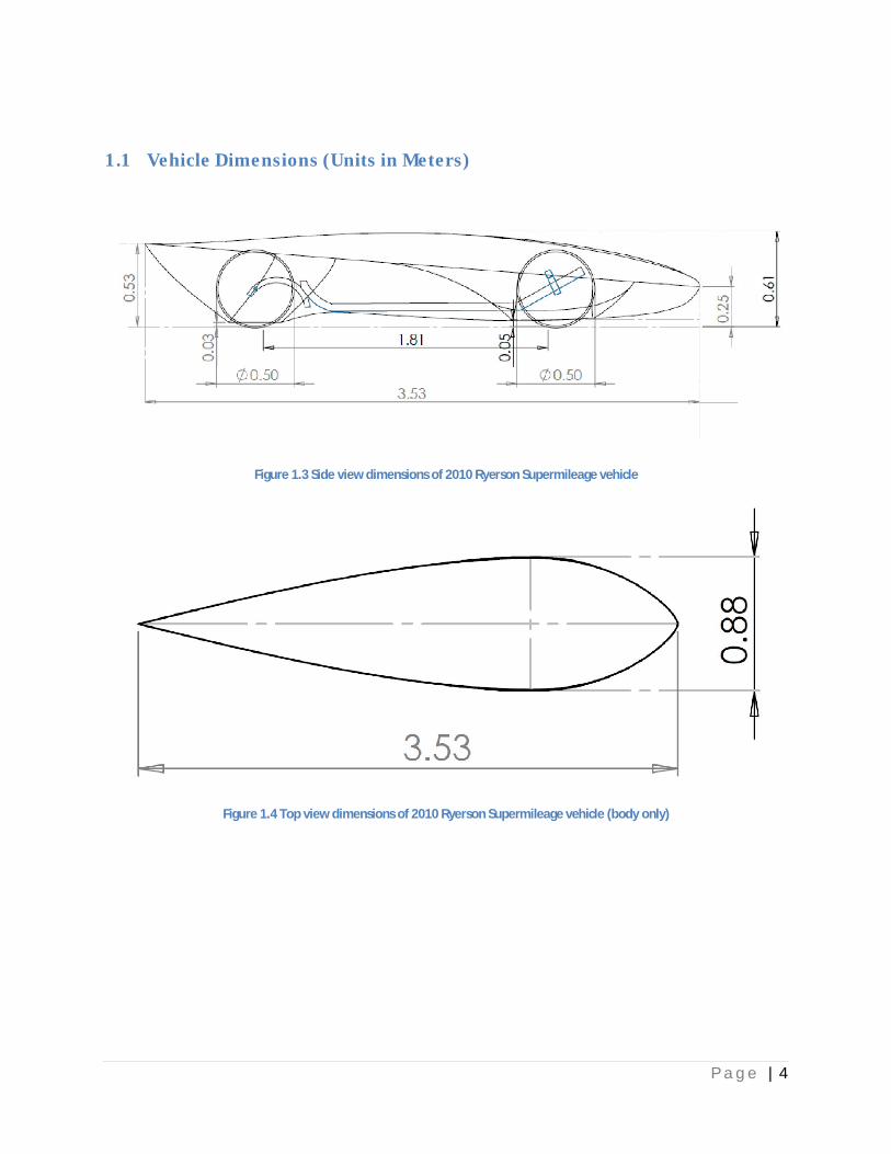
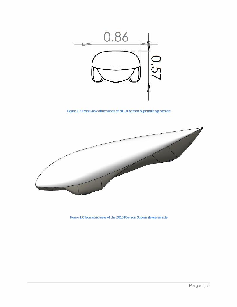
Figure 1.5 Front view dimensions of 2010 Ryerson Supermileage vehicle
Figure 1.6 Isometric view of the 2010 Ryerson Supermileage vehicle
P a g e | 6
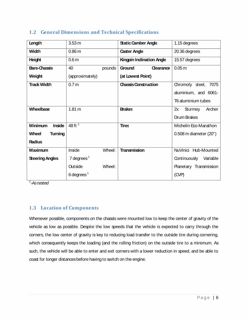
1.2 General Dimensions and Technical Specifications
Length 3.53 m Static Camber Angle 1.15 degrees
Width 0.86 m Caster Angle 20.36 degrees
Height 0.6 m Kingpin Inclination Angle 15.57 degrees
Bare-Chassis
Weight
40 pounds
(approximately)
Ground Clearance
(at Lowest Point)
0.05 m
Track Width 0.7 m Chassis Construction Chromoly steel, 7075
aluminium, and 6061-
T6 aluminium tubes
Wheelbase 1.81 m Brakes 2x Sturmey Archer
Drum Brakes
Minimum Inside
Wheel Turning
Radius
48 ft 1 Tires Michelin Eco-Marathon
0.508 m diameter (20”)
Maximum
Steering Angles
Inside Wheel:
7 degrees 1
Outside Wheel:
6 degrees 1
Transmission NuVinici Hub-Mounted
Continuously Variable
Planetary Transmission
(CVP)
1-As tested
1.3 Location of Components
Whenever possible, components on the chassis were mounted low to keep the center of gravity of the
vehicle as low as possible. Despite the low speeds that the vehicle is expected to carry through the
corners, the low center of gravity is key to reducing load transfer to the outside tire during cornering,
which consequently keeps the loading (and the rolling friction) on the outside tire to a minimum. As
such, the vehicle will be able to enter and exit corners with a lower reduction in speed, and be able to
coast for longer distances before having to switch on the engine.

P a g e | 7
1.3.1 Location of Components in Vehicle
Note: Not all components shown in figure.
1.4 Chassis Modifications
Modifications were performed on the original recumbent trike frame to lengthen the chassis with 0.6 m
of 6061-T6 aluminum tubing, which was slightly longer than required to accommodate changes in the
vehicle’s wheelbase if needed in a future (i.e.: lengthening of the chassis to accommodate more running
gear, or shortening of the chassis to meet the minimum required turning circle). An easily-removed
Engine, Fuel Bottle, Starter Motor,
Electronic Spark Ignition Controller and
Compact Starter Battery
20” Diameter Front Tires 20” Diameter Rear Tires
Tubular Steel Seat with
Three Point Seatbelt
Roll Hoop
Internal Hub Continuously Variable
Planetary Transmission
Tiller Steering System with Left and Right
Brake Actuators and Gearbox Shifter
Fire Extinguisher and Batteries
for Electrical Systems (Under
Seat)
Drum Brake Units (Hub Mounted)

P a g e | 8
tubular steel seat was outfitted on the vehicle from the factory, but the seating position was high and
not in-line with the team’s goal of lowering the frontal surface area of the body to a minimum. Thus,
selected cross-members of the tubular seat were removed to accommodate for the lowest possible
seating position.
Figure 1.7 Underside of tubular steel seat with modified cross members
After extensive modifications, an impressively low vehicle height of 0.6 m with the driver seated in the
car was permissible. This vehicle height was significantly shorter than the 2007 Ryerson Supermileage
vehicle, in which the driver sat in a typical automobile-like upright configuration. On the other hand, the
length of the 2010 Ryerson Supermileage vehicle has to be longer to accommodate for the much lower
reclined seating position of the driver. At the rear of the vehicle, the team had decided to remove the
polyurethane bushing for damping that was supplied with the recumbent for a stiffly sprung chassis.
This allowed the rear ride height of the vehicle to be lowered considerably from stock and also
permitted the team to design a vehicle body that could sit closer to the rear tire because provisions for
body clearance due to up/down wheel travel no longer have to be made. By lowering the rear of the
vehicle frame from removal of the polyurethane bushing, an increase in the caster angle at the front
steering geometry resulted, but the increased caster was deemed beneficial because of the added self-
centering effect of the vehicle when it encounters external disturbances such as cross-winds or
imperfections in the road.
P a g e | 9
In order to meet the safety requirements of the Supermileage competition, the tubular steel roll hoop
from the 2007 Ryerson Supermileage vehicle was placed on the chassis temporarily. Measurements with
the team’s two candidate drivers outfitted with the racing helmet were taken, and results indicated that
2.5 to 3 inches of clearance was available between the highest point of the drivers’ helmets and the top
of the roll hoop (considering a roll hoop that has a height of 0.6m when measured from the ground
plane).
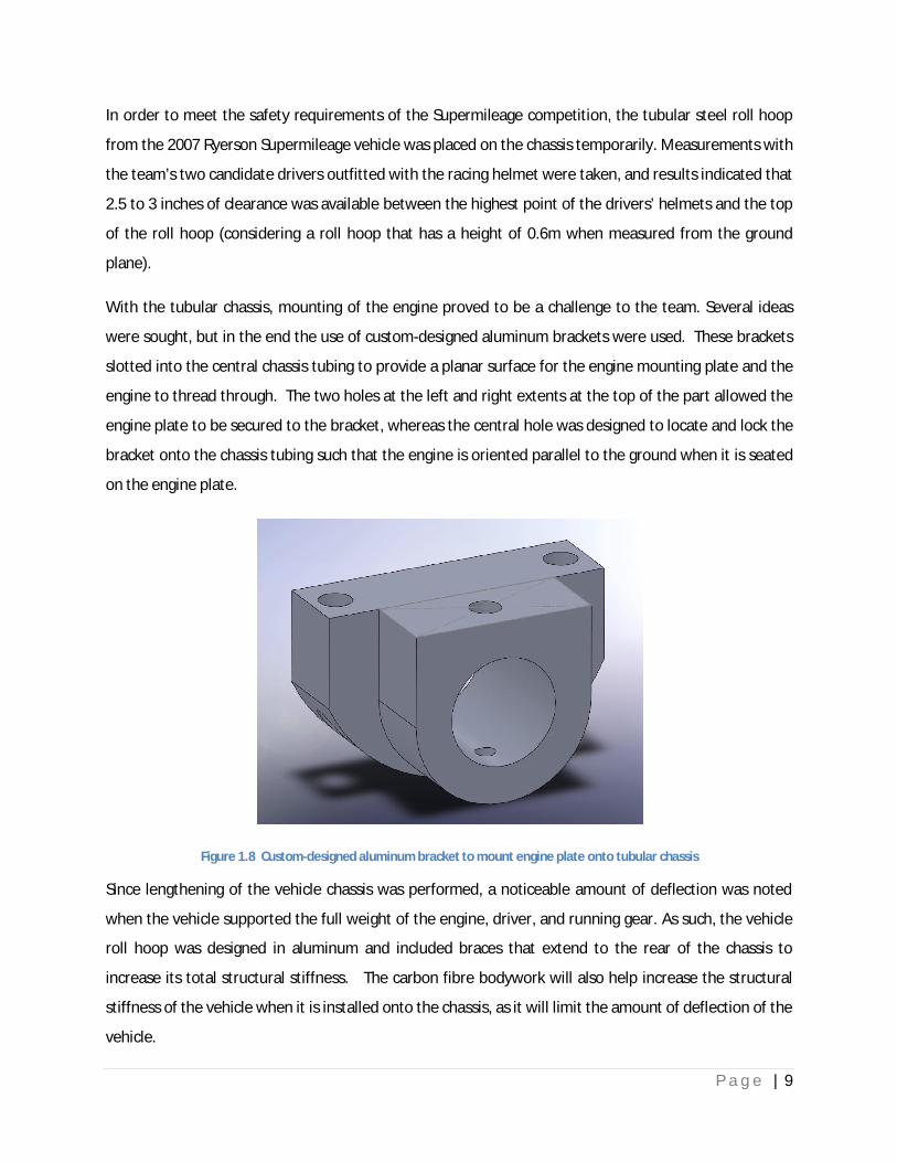
With the tubular chassis, mounting of the engine proved to be a challenge to the team. Several ideas
were sought, but in the end the use of custom-designed aluminum brackets were used. These brackets
slotted into the central chassis tubing to provide a planar surface for the engine mounting plate and the
engine to thread through. The two holes at the left and right extents at the top of the part allowed the
engine plate to be secured to the bracket, whereas the central hole was designed to locate and lock the
bracket onto the chassis tubing such that the engine is oriented parallel to the ground when it is seated
on the engine plate.
Figure 1.8 Custom-designed aluminum bracket to mount engine plate onto tubular chassis
Since lengthening of the vehicle chassis was performed, a noticeable amount of deflection was noted
when the vehicle supported the full weight of the engine, driver, and running gear. As such, the vehicle
roll hoop was designed in aluminum and included braces that extend to the rear of the chassis to
increase its total structural stiffness. The carbon fibre bodywork will also help increase the structural
stiffness of the vehicle when it is installed onto the chassis, as it will limit the amount of deflection of the
vehicle.
P a g e | 10
2 Engine
Due to the team’s lack of expertise with engine tuning and lack of active team members and resources,
the optimization of the engine was not a core emphasis for this year’s competition. The team foresees
that the stock Briggs & Stratton engine provided by SAE will be used with no modifications, except the
installation of an electric start system and electronic spark ignition. The ability to switch on/off the
engine during the competition is a prime factor in improving the fuel consumption of the vehicle, and
the electronic spark ignition system allows for minor tuning of the spark timing for improved engine
efficiency over the stock design.
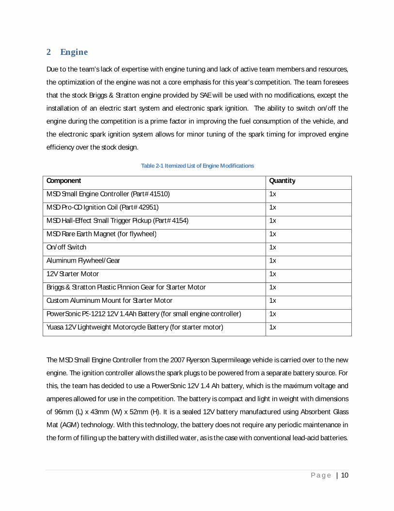
Table 2-1 Itemized List of Engine Modifications
Component Quantity
MSD Small Engine Controller (Part# 41510) 1x
MSD Pro-CD Ignition Coil (Part# 42951) 1x
MSD Hall-Effect Small Trigger Pickup (Part# 4154) 1x
MSD Rare Earth Magnet (for flywheel) 1x
On/off Switch 1x
Aluminum Flywheel/Gear 1x
12V Starter Motor 1x
Briggs & Stratton Plastic Pinnion Gear for Starter Motor 1x
Custom Aluminum Mount for Starter Motor 1x
PowerSonic PS-1212 12V 1.4Ah Battery (for small engine controller) 1x
Yuasa 12V Lightweight Motorcycle Battery (for starter motor) 1x
The MSD Small Engine Controller from the 2007 Ryerson Supermileage vehicle is carried over to the new
engine. The ignition controller allows the spark plugs to be powered from a separate battery source. For
this, the team has decided to use a PowerSonic 12V 1.4 Ah battery, which is the maximum voltage and
amperes allowed for use in the competition. The battery is compact and light in weight with dimensions
of 96mm (L) x 43mm (W) x 52mm (H). It is a sealed 12V battery manufactured using Absorbent Glass
Mat (AGM) technology. With this technology, the battery does not require any periodic maintenance in
the form of filling up the battery with distilled water, as is the case with conventional lead-acid batteries.

P a g e | 11
This liquid-free configuration makes it possible to place the battery in any orientation within the vehicle,
allowing it to be located more easily on the chassis for a low center of gravity.
For the starter motor, a significantly more powerful battery is necessary to provide ample cranking amps
for the motor. Conventional automotive batteries on the market weigh between 25 to 40 pounds,
depending on their capacity. Batteries designed for automobile racing are available in much more
compact sizes and large weight savings. The lightest battery the team discover was a Braille B106
battery for track-day racing use. This battery weighs a mere 6.6 pounds and is sufficient to crank start a
small 4-cylinder engine. However, further research revealed that a yet lighter battery could be used to
crank start this year’s Supermileage vehicle. This battery was the Yuasa YT-Z7S, which weighs lighter
than the Braille battery at a mere 4.6 pounds. The battery is rated at 12 volts and 6Ah, and is used as
original equipment on motorcycles with engines as large as 450cc. Its compact dimensions at 113mm (L)
x 70mm (W) x 105mm (H), and its AGM technology allows the battery to be placed in any orientation
within the vehicle chassis. Since the SAE-supplied Briggs & Stratton engine is merely 125cc, there should
be no issues with cranking the engine with the battery’s 130 Cold Cranking Amps (CCA) rating.
Furthermore, it was reported that this battery is sufficiently powerful to crank the four-cylinder engine
in a Mazda Miata designed for racing. Thus, the Yuasa YTZ-7S battery was chosen as the battery of
choice for this year’s vehicle.
Figure 2.1 Physical size of the Yuasa YTZ-7S battery

P a g e | 12
For the most direct powertrain connection possible and the highest possible mechanical efficiency, the
engine is mounted aft of the roll hoop behind the driver. In this configuration, the power loss is kept to
a minimum, as the driven wheel is immediately behind the engine. Figure 2.2 shows the mounting
location of the engine on the engine on the chassis. The starter motor and starter battery are mounted
in front of the engine in close proximity on the aluminum engine plate.
Figure 2.2 Mounting location of the engine on the chassis
Figure 2.3 Aluminum flywheel on engine and starter motor on custom fixture
P a g e | 13
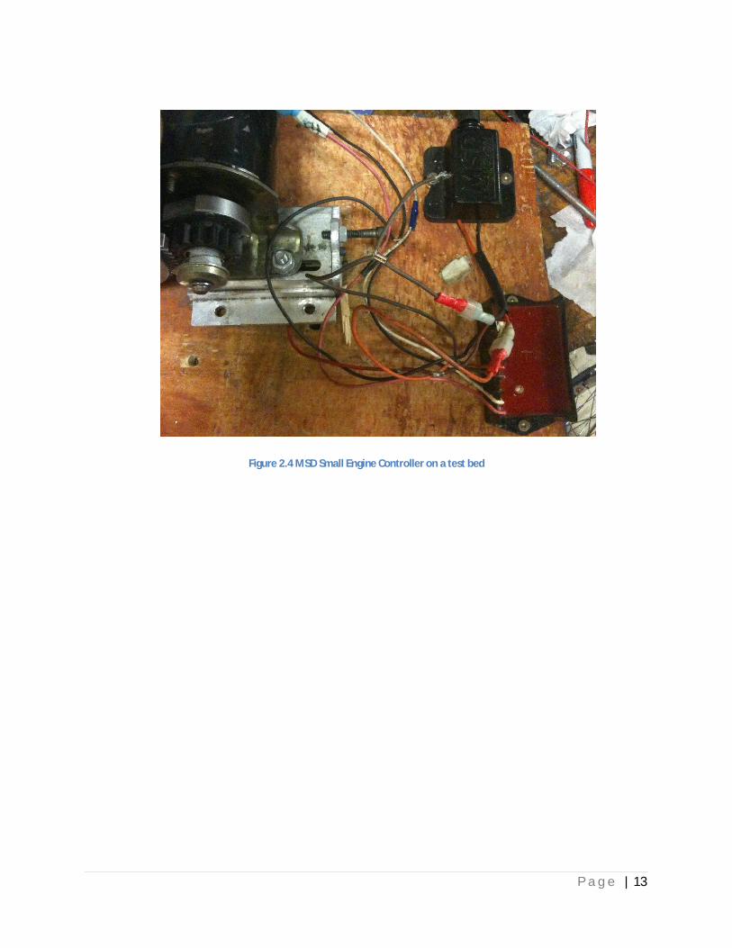
Figure 2.4 MSD Small Engine Controller on a test bed
P a g e | 14
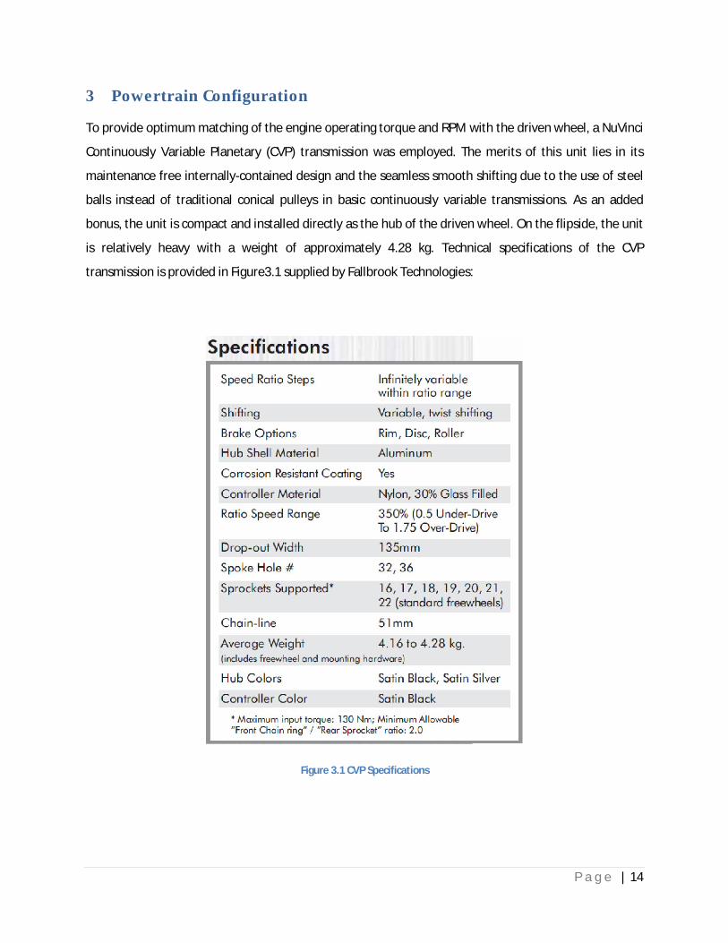
3 Powertrain Configuration
To provide optimum matching of the engine operating torque and RPM with the driven wheel, a NuVinci
Continuously Variable Planetary (CVP) transmission was employed. The merits of this unit lies in its
maintenance free internally-contained design and the seamless smooth shifting due to the use of steel
balls instead of traditional conical pulleys in basic continuously variable transmissions. As an added
bonus, the unit is compact and installed directly as the hub of the driven wheel. On the flipside, the unit
is relatively heavy with a weight of approximately 4.28 kg. Technical specifications of the CVP
transmission is provided in Figure3.1 supplied by Fallbrook Technologies:
Figure 3.1 CVP Specifications
P a g e | 15
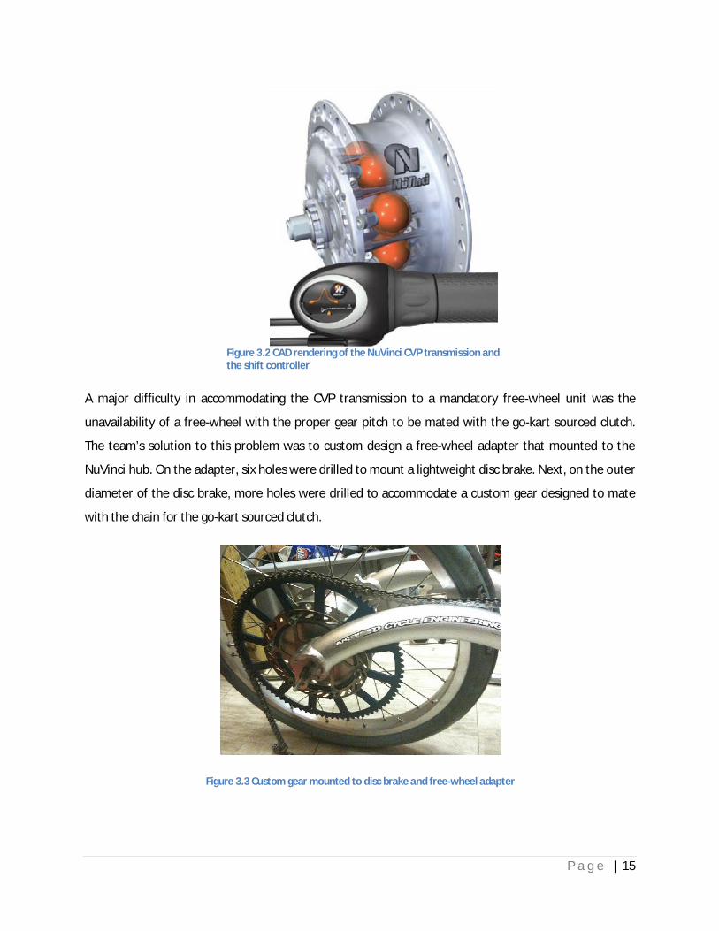
A major difficulty in accommodating the CVP transmission to a mandatory free-wheel unit was the
unavailability of a free-wheel with the proper gear pitch to be mated with the go-kart sourced clutch.
The team’s solution to this problem was to custom design a free-wheel adapter that mounted to the
NuVinci hub. On the adapter, six holes were drilled to mount a lightweight disc brake. Next, on the outer
diameter of the disc brake, more holes were drilled to accommodate a custom gear designed to mate
with the chain for the go-kart sourced clutch.
Figure 3.3 Custom gear mounted to disc brake and free-wheel adapter
Figure 3.2 CAD rendering of the NuVinci CVP transmission and the shift controller

P a g e | 16
Theoretically, the 350% speed ratio range of the CVP makes it possible for the team to operate the
engine at a constant design RPM for maximum fuel efficiency. Based on the minimum allowable vehicle
speed of 24 km/h and the maximum allowable vehicle speed of 40 km/h, it was deemed possible to
operate the engine at a constant fuel-economical RPM and accelerate the vehicle by means of changing
the ratio of the CVP transmission. An alternative means of accelerating the vehicle (should testing reveal
problems with the aforementioned approach) is to select the desired ratio on the CVP transmission and
leave it static throughout the competition, and instead, to change the engine speed to propel the
vehicle to higher speeds.
On the engine, a Tomar Racing clutch designed for go karts was employed. This clutch was carefully
selected for its smooth engaging and lack of engine bog-down characteristics, which both contribute to
smoother driving and reduced likelihood of engine stall when operating the engine at lower RPMs. A
series of six springs is used on the clutch for easy adjustment of the clutch engagement point to allow
the proper idle RPM to be set, and an assortment of gears with different teeth are available for proper
matching of the required speed and RPM.
Figure 3.4 The clutch unit as used on the 2010 Ryerson Supermileage Vehicle

P a g e | 17
4 Brake System
A pair of Sturmey-Archer X-FD drum brakes were fitted to this years’ vehicle. These drum brakes were
one of a few braking systems that could be used directly on the chassis from the recumbent
manufacturer. A secondary alternative was the use of a pair of disc brakes, which are more costly but
provide better braking power. From experience, a vehicle’s front braking system is the primary
contributor in stopping a vehicle at speed. This is due to the forward weight transfer of the car as
braking action is applied, which naturally shifts more load to the front wheels, and consequently,
provide them with better grip for increased stopping power. For this vehicle, since a pair of brakes were
used on the front of the vehicle (vs. the single disc brake used on the rear of the 2007 Ryerson
Supermileage vehicle), the team estimated a sufficient braking force to stop the car from 24 km/h within
a 4m stretch of road as per the Supermileage rules. As the recumbent was designed for regular speeds
as high as 50 km/h, it was believed that the drum brake system is more than sufficient for the
Supermileage competition’s 40 km/h upper speed limit. Since theoretical calculations of the drum
brakes’ combined stopping power and energy capacity would not take into account the frictional forces
available at the front tires, the amount of weight transferred to the front tires during braking, or the
braking power (the amount of brake fade present) of the drum brakes after repeated use, physical tests
of the vehicle’s brakes consistent with the Supermileage rules’ brake test were conducted.
Figure 4.1 Sturmey-Archer hub-mounted drum brake unit

P a g e | 18
Figure 4.2 Ramp used to accelerate vehicle up to 24km/h
The low ride ground clearance of the Supermileage vehicle was designed for smooth tracks, such as the
competition grounds in Michigan. Thus, to avoid damage to the bottom of the chassis during braking
tests, a long hallway within Ryerson University was used after school hours to conduct the test. To
simulate the full running weight of the completed vehicle, a team member weighing 200 pounds was
used in the tests instead of the designated vehicle driver, who weighs 160 pounds. The 40 additional
pounds was a reasonable assumption for the weight of the engine, batteries, starter motor, etc., which
will be added to the vehicle as it nears its completion in June. In order to accelerate the vehicle up to
24km/h for the brake tests, the vehicle was pushed off a ramp at one end of the corridor. An onboard
bicycle computer provided an accurate indication of the vehicle’s instantaneous speed. Each braking
trial consisted of the driver actuating the left and right brakes fully as soon as the vehicle has reached 1)
at least 24km/h, and 2) a floor marker where a tape measure was set for measurements braking
distance measurements. Over a series of twelve test runs, the vehicle was able to stop completely
within a 4m stretch of the hallway. Since the floor material was linoleum, the tires skidded partially
when the brakes were applied, but the vehicle was still able to stop well within the 4m length marked on
the floor. At the competition proving grounds in Michigan with a proper race track surface, the team
does not expect little to no skidding of the tires to take place under hard braking. Therefore, the
skidding present within the brake tests could be viewed as a safety factor added on top of the 40
pounds of extra payload estimated on the final vehicle. The braking tests were consistently successful
and the team does not expect any problems with the vehicle’s braking performance during the
competition.

P a g e | 19
5 Suspension and Running Gear
The suspension geometry of the vehicle were determined largely by its stock configuration from the
recumbent frame. However, a considerable increase in the caster angle resulted from removing the rear
polyurethane damping bushing from the vehicle, which lowered the pitch of the longitudinal chassis
tubing and consequently increased the caster angle. By carefully measuring the steering geometry
dimensions, the static camber angle, caster angle, and kingpin inclination angle were determined to be
1.15 degrees, 20.36 degrees, and 15.57 degrees, respectively. Of these, the caster angle was relatively
large. On the one hand, the large caster angle will help the vehicle maintain a straighter heading when it
is travelling in the forward direction because of its self-stabilizing and self-centering effect. This is
beneficial to the vehicle’s performance, as it will become less susceptible to external disturbances from
cross-winds and road imperfections. By the same token, the driver will not need to make as many
steering adjustments to correct for the straight heading of the vehicle, minimizing frictional drag from
constant steering adjustments, which allows a longer coasting distance of the vehicle between the
switching on/off of the engine for acceleration. As the vehicle was significantly lengthened from stock to
accommodate a lower, more reclined seating position and the volume required by extra running gear,
the Ackerman steering geometry must be corrected to reduce the frictional interplay between the three
wheels during cornering.
Initially, the vehicle was set at a wheelbase of 1.91m after careful measurements of the required
dimensions for all running gear and driver when packaged underneath the vehicle body. During parking
lot tests, however, it was determined that large steering angles were required to scribe the mandatory
15.2m maximum inside wheel turning radius. This was not a big concern on the chassis, as the tiller
steering system had not reached full lock yet. However, the unusually large steering angles created
noticeable clearance issues for the body work, especially around the front wheel fairings. As a result, the
team had to:
a) revise the steering geometry to correct for neutral ackerman steering
b) shorten the wheelbase of the chassis as much as possible to reduce the steering angles required
to scribe the 15.2m maximum inside wheel turning radius
c) increase the width of the body to accommodate for the higher than expected steering angles.

P a g e | 20
To increase the width of the body and hence, its associated frontal area, was not an attractive
option at this point. As well, although the steering could be corrected for neutral Ackerman, it was
deemed to try to contract the vehicle’s wheelbase as much as possible first. By trimming off excess
material on the engine plate and taking more careful measurements of the vehicle with all major
onboard gear and driver, it was possible to reduce the vehicle’s wheelbase by 0.1m to 1.81m.
Several advantages resulted from this modification:
1) the chassis has a lower deflection
2) a reduced volume of bodywork was required, making it possible to lower the vehicle’s weight
from before
3) the surface area of the body has been reduced for lower surface drag and better aerodynamic
performance.
To determine if the shortened wheelbase was sufficient to provide small enough steering angles to clear
the wheel fairings on the body, an accurate SolidWorks model of the chassis with the proper steering
geometry was created. Unfortunately, due to the contribution of the static camber angle, caster angle,
kingpin inclination, and uncertain slip angles at speed, the approach was abandoned for a more accurate
test in a large parking lot. In the parking lot, markings were added onto the ground to recreate the
15.2m inside wheel turning radius. Wooden planks were placed at the diameter of the circle, and the
vehicle was located with its inside wheel beside adjacent to the wooden plank and the chassis tube
parallel to the same plank.
In preparation for the steering angle test, the tiller steering was locked with clamps at a static steering
angle and the vehicle (with driver) was pushed from behind by a team member at both low and high
speeds. Tests were conducted at the two speeds to ensure that the tire slip angles introduced to the
vehicle at high speeds would not hinder the turning circle performance achieved at the lower speed.
After performing a series of tests at various static steering angles, it was deemed that 7 degrees and 6
degrees of steering angle was required for the outside tire and inside tire, respectively. This was a
notable improvement over the previous steering angles obtained when the vehicle was configured at
the 1.91m wheelbase.
P a g e | 21
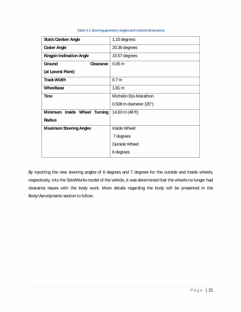
Table 5-1 Steering geometry angles and related dimensions
Static Camber Angle 1.15 degrees
Caster Angle 20.36 degrees
Kingpin Inclination Angle 15.57 degrees
Ground Clearance
(at Lowest Point)
0.05 m
Track Width 0.7 m
Wheelbase 1.81 m
Tires Michelin Eco-Marathon
0.508 m diameter (20”)
Minimum Inside Wheel Turning
Radius
14.63 m (48 ft)
Maximum Steering Angles Inside Wheel:
7 degrees
Outside Wheel:
6 degrees
By inputting the new steering angles of 6 degrees and 7 degrees for the outside and inside wheels,
respectively, into the SolidWorks model of the vehicle, it was determined that the wheels no longer had
clearance issues with the body work. More details regarding the body will be presented in the
Body/Aerodynamic section to follow.

P a g e | 22
Figure 5.1 Front view of chassis showing camber and kingpin inclination angles
Figure 5.2 Side view of chassis showing caster angle
For the driver to control the vehicle heading in a safe and predictable manner, a tiller steering system is
featured on the vehicle. In this system, the driver’s hands must be placed on the handlebars at all times,
which helps balance the steering linkages such that quick adjustments to vehicle heading can be made
with ease when external disturbances jerk the tiller steering from the driver’s hands. An advantage of
the specified tiller steering system is the ability to set the toe angle of the front tires independently as

P a g e | 23
necessary with the tie-rods to fine-tune the handling performance and minimization of rolling friction as
required.
Figure 5.3 Front view of vehicle frame with tiller steering shown
Equipped with 20” Michelin ultra-low friction eco-marathon tires, the power loss of the drivetrain due to
rolling-friction is reduced. This reduction in friction entails a lower drop in vehicle speed (and higher
coasting range) when the engine is switched off for gains in fuel economy. The low rolling friction will
also enable the vehicle to negotiate corners with a lower loss in speed and less adversely impacted by
large load transfer (and consequently, a proportionally large amount of rolling friction) to the outside
tires.
Figure 5.4 20” Michelin ultra-low friction eco-marathon tire
P a g e | 24
.
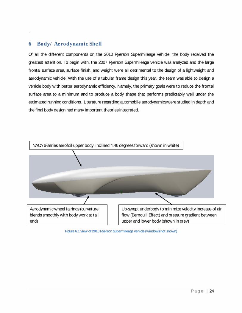
6 Body/ Aerodynamic Shell
Of all the different components on the 2010 Ryerson Supermileage vehicle, the body received the
greatest attention. To begin with, the 2007 Ryerson Supermileage vehicle was analyzed and the large
frontal surface area, surface finish, and weight were all detrimental to the design of a lightweight and
aerodynamic vehicle. With the use of a tubular frame design this year, the team was able to design a
vehicle body with better aerodynamic efficiency. Namely, the primary goals were to reduce the frontal
surface area to a minimum and to produce a body shape that performs predictably well under the
estimated running conditions. Literature regarding automobile aerodynamics were studied in depth and
the final body design had many important theories integrated.
Figure 6.1 view of 2010 Ryerson Supermileage vehicle (windows not shown)
NACA 6-series aerofoil upper body, inclined 4.46 degrees forward (shown in white)
Up-swept underbody to minimize velocity increase of air
flow (Bernoulli Effect) and pressure gradient between
upper and lower body (shown in grey)
Aerodynamic wheel fairings (curvature
blends smoothly with body work at tail
end)

P a g e | 25
Figure 6.2 Isometric view of 2010 Ryerson Supermileage vehicle (windows not shown)
Figure 6.3 Top view of 2010 Ryerson Supermileage vehicle (windows not shown)
Sharp pointed tail to reduce vortex-induced drag at rear of vehicle
Streamlined top profile derived from tear-drop shape

P a g e | 26
This design represented many hours of careful spline modelling in SolidWorks. Various NACA wing
profiles were generated and their coordinates inputted into SolidWorks to sketch the exact shape for
use on the upper body. In the end, the upper body was based on a NACA 64-012 aerofoil inclined
forward 4.46 degrees such that the highest point of the aerofoil was directly above the roll hoop (the
highest point of the chassis). Preliminary analysis of this aerofoil on an internet-based Java applet at
http://www.mh-aerotools.de estimated an aerofoil-only drag coefficient of 0.0451 when the aerofoil is
pitched forward by 4.46 degrees.
Figure 6.4 Preliminary Java CFD simulation of NACA 64-012 aerofoil inclined at 4.46 degrees with respect to ground
P a g e | 27
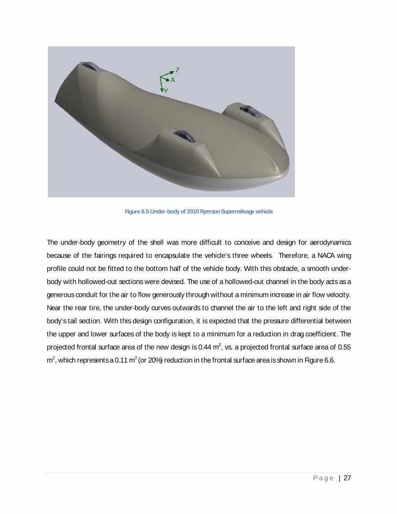
Figure 6.5 Under-body of 2010 Ryerson Supermileage vehicle
The under-body geometry of the shell was more difficult to conceive and design for aerodynamics
because of the fairings required to encapsulate the vehicle’s three wheels. Therefore, a NACA wing
profile could not be fitted to the bottom half of the vehicle body. With this obstacle, a smooth under-
body with hollowed-out sections were devised. The use of a hollowed-out channel in the body acts as a
generous conduit for the air to flow generously through without a minimum increase in air flow velocity.
Near the rear tire, the under-body curves outwards to channel the air to the left and right side of the
body’s tail section. With this design configuration, it is expected that the pressure differential between
the upper and lower surfaces of the body is kept to a minimum for a reduction in drag coefficient. The
projected frontal surface area of the new design is 0.44 m2, vs. a projected frontal surface area of 0.55
m2, which represents a 0.11 m2 (or 20%) reduction in the frontal surface area is shown in Figure 6.6.

P a g e | 28
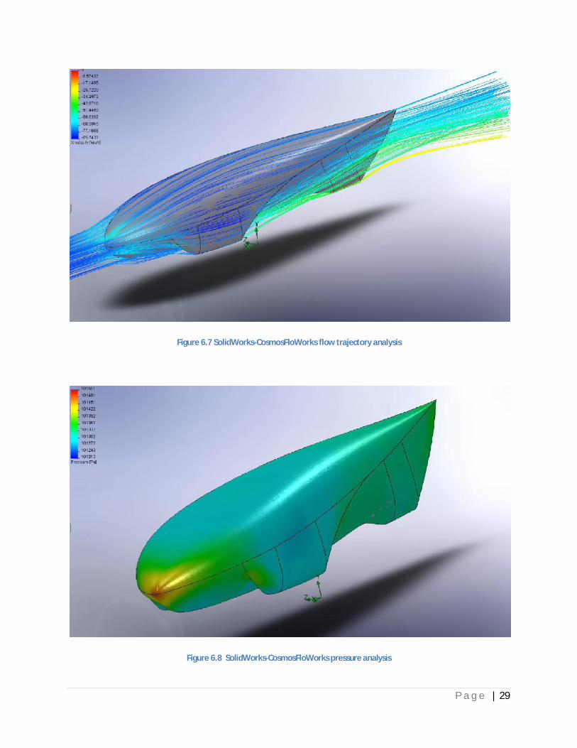
Computational Fluid Dynamics simulation in SolidWorks of the body with a simulated air velocity of 85
km/h (40km/h vehicle top speed + estimated 45km/h opposing wind speed) revealed that a low drag
coefficient of 0.088 was theoretically possible with this body design. A 1/15th scale rapid-prototype
model of both the new and old body designs have been created using a 3D printer for wind-tunnel
testing to validate these results.
Figure 6.6 Projected frontal surface area of the 2007 body (left) vs. the 2010 body
P a g e | 29
Figure 6.7 SolidWorks-CosmosFloWorks flow trajectory analysis
Figure 6.8 SolidWorks-CosmosFloWorks pressure analysis
P a g e | 30
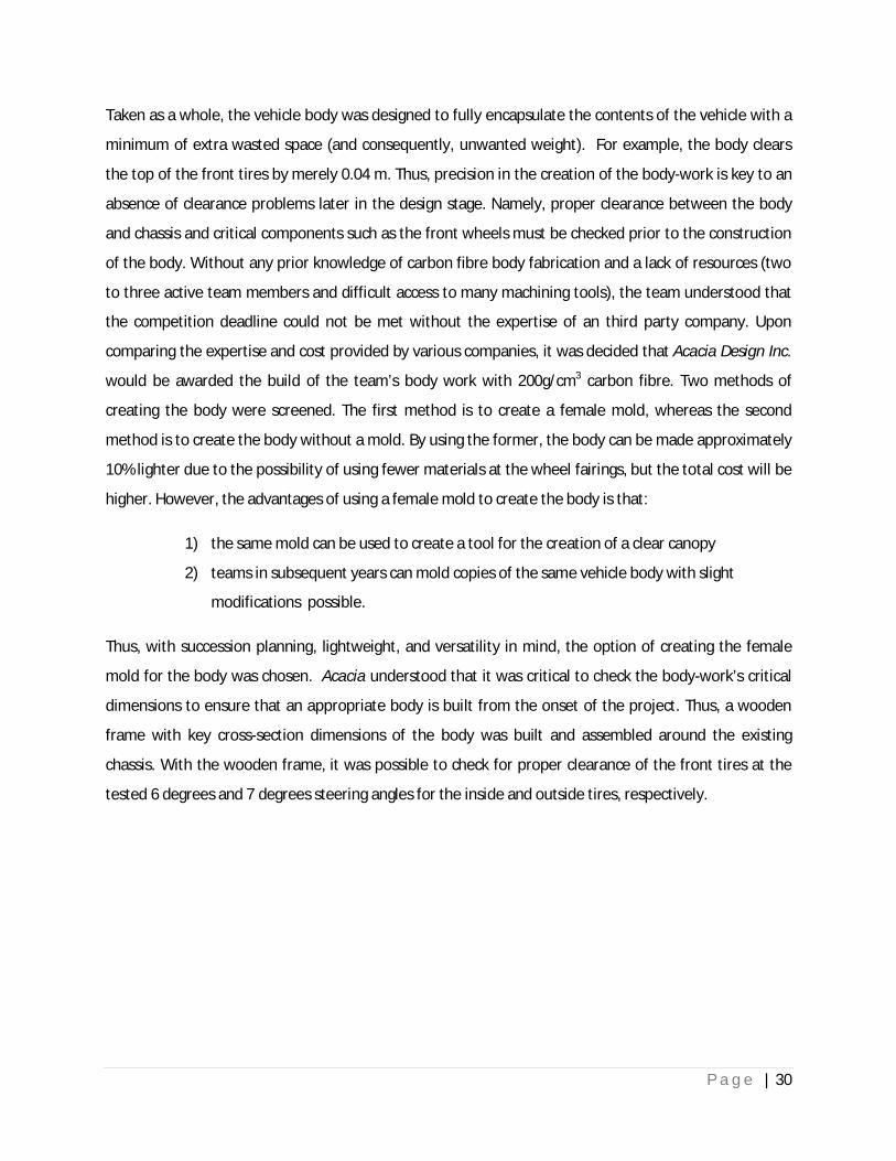
Taken as a whole, the vehicle body was designed to fully encapsulate the contents of the vehicle with a
minimum of extra wasted space (and consequently, unwanted weight). For example, the body clears
the top of the front tires by merely 0.04 m. Thus, precision in the creation of the body-work is key to an
absence of clearance problems later in the design stage. Namely, proper clearance between the body
and chassis and critical components such as the front wheels must be checked prior to the construction
of the body. Without any prior knowledge of carbon fibre body fabrication and a lack of resources (two
to three active team members and difficult access to many machining tools), the team understood that
the competition deadline could not be met without the expertise of an third party company. Upon
comparing the expertise and cost provided by various companies, it was decided that Acacia Design Inc.
would be awarded the build of the team’s body work with 200g/cm3 carbon fibre. Two methods of
creating the body were screened. The first method is to create a female mold, whereas the second
method is to create the body without a mold. By using the former, the body can be made approximately
10% lighter due to the possibility of using fewer materials at the wheel fairings, but the total cost will be
higher. However, the advantages of using a female mold to create the body is that:
1) the same mold can be used to create a tool for the creation of a clear canopy
2) teams in subsequent years can mold copies of the same vehicle body with slight
modifications possible.
Thus, with succession planning, lightweight, and versatility in mind, the option of creating the female
mold for the body was chosen. Acacia understood that it was critical to check the body-work’s critical
dimensions to ensure that an appropriate body is built from the onset of the project. Thus, a wooden
frame with key cross-section dimensions of the body was built and assembled around the existing
chassis. With the wooden frame, it was possible to check for proper clearance of the front tires at the
tested 6 degrees and 7 degrees steering angles for the inside and outside tires, respectively.
P a g e | 31
Figure 6.9 Front view of wooden frame for dimensions/clearance check
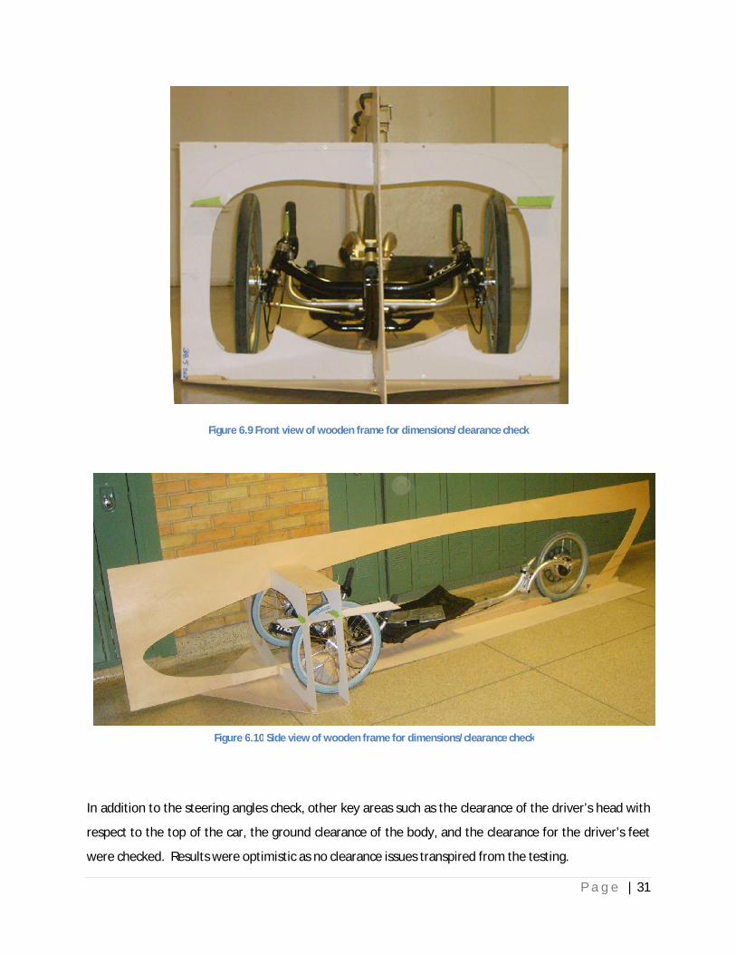
In addition to the steering angles check, other key areas such as the clearance of the driver’s head with
respect to the top of the car, the ground clearance of the body, and the clearance for the driver’s feet
were checked. Results were optimistic as no clearance issues transpired from the testing.
Figure 6.10 Side view of wooden frame for dimensions/clearance check

P a g e | 32
To allow the driver to see the road ahead with good visibility, a clear canopy with reasonable optical
clarity is sought. A compromise between lightweight design, reduction of projected frontal area, optical
clarity, and manufacturability were sought.
Two designs were conceived in SolidWorks. The first is one remained true in form to the originally CFD
tested body by using either a large clear canopy or the insetting of window panels flush with the rest of
the body work. Figure 6.11 shows a SolidWorks rendering of this design with molded window panels.
The use of the molded window panels makes it possible to slightly reduce the weight of the vehicle
body, since the candidate materials for the windows are both heavier than the carbon fibre body. An
alternative is to mold a full-sized clear canopy, as shown by the white perimeter line on the body in
Figure 6.11. The advantage of this approach is a more refined canopy with fewer interfaces between the
windows and the rest of the body. Namely, by using three separate windows on the body, there will be
three separate interfaces between the body and the windows. However, by using a full-sized one piece
molded canopy, there will be no extra interfaces between the canopy and the body, since the canopy
must swivel upwards along the white perimeter line in Figure 6.11 to allow the driver to enter or exit
the vehicle. By factoring in the need for a 160 degrees field of vision from the driver’s eyes, it was
decided that the amount of weight savings that can be afforded by using three windows vs. one full-
sized canopy is minimal. The explanation for this is the relatively narrow A-pillars (narrower than that
shown in Figure 6.11) that will be used for the design with three windows. Therefore, the weight
savings of using three clear windows is minimal, and the use of a full-sized canopy is more favourable
from a higher visibility and better surface finish perspective.
An alternative to the aforementioned configuration for the vehicle canopy is the raise the seating
position of the driver. In this approach, the windscreen required for the driver is significantly smaller,
allowing for a favourable reduction in body weight and easier manufacturability (see Figure 6.12). On
the other hand, the projected frontal area of the body is increased as a result, and the originally
designed aerodynamic form of the body is interrupted by the blister/bubble created on the body to
accommodate the driver’s head.

P a g e | 33
Figure 6.11 SolidWorks rendering of the 2010 body design with streamlined canopy
Figure 6.12 SolidWorks rendering of the 2010 body design with small-windscreen style canopy

P a g e | 34
Polycarbonate and acrylic were the two candidate materials to be used to construct the canopy of the
2010 vehicle body. The final choice of material would depend on the expertise of the company forming
the canopy. Acrylic is known to have inherently better optical clarity, but at the cost of higher
brittleness. Polycarbonate, on the other hand, is less brittle, but has worse optical clarity and is more
prone to surface scratches.
Visits to several plastic molding companies were planned, and in the end the team had found a company
that had the expertise and equipment to create a high optical clarity full-sized canopy for use on the
vehicle. Thus, the design direction for the body was pushed towards better road visibility for the driver,
lower projected frontal surface area, and better surface finish at the expense of a somewhat heavier
body. The company responsible for the molding of the clear canopy, Plas-Tech Inc., has shown
enthusiasm towards the team’s Supermileage project and has agreed to sponsor the team by offering a
much discounted price for the labour and materials of the canopy molding. In addition, Plas-Tech also
agreed to mold two canopies, one with acrylic, and one with polycarbonate, to allow the team to
compare the two options before implementing the most suitable one for the vehicle.

P a g e | 35
7 Performance
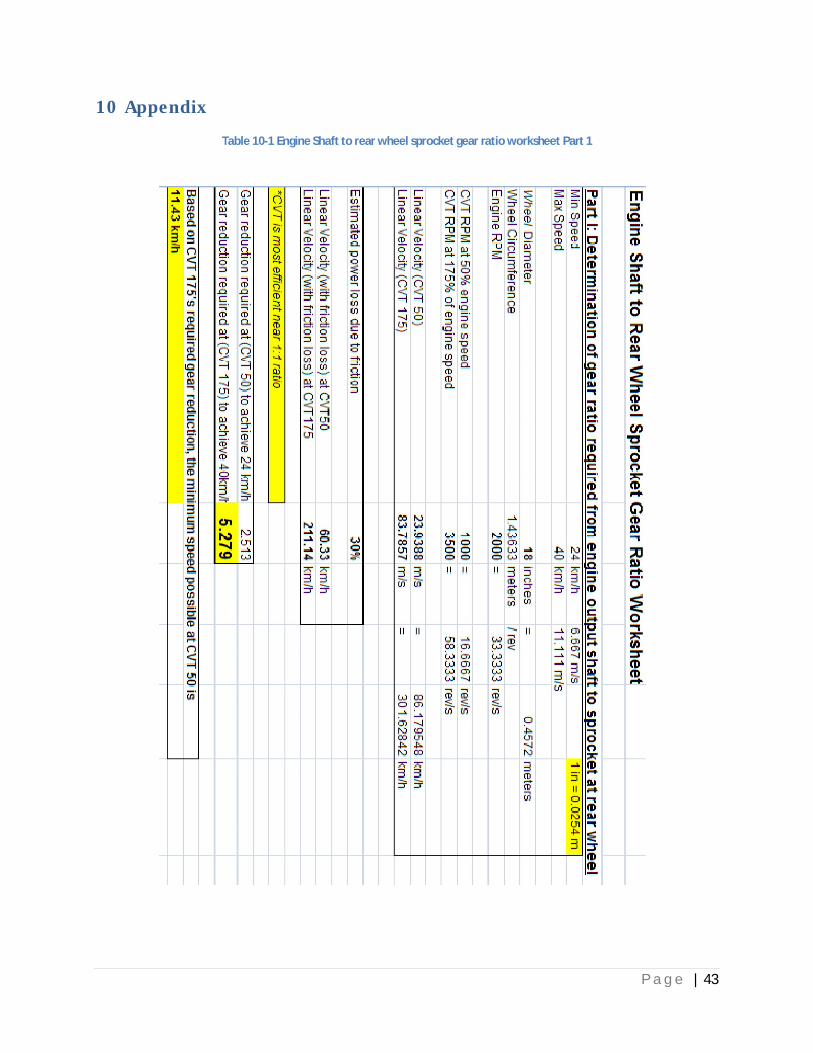
At this time of the project, no fuel economy calculations have been conducted. However, analysis of the
required gear ratio between the engine output shaft and the sprocket at the rear wheel was conducted.
This analysis made it possible to determine the best possible gear ratio selection assuming that the
engine speed is held stationary at 2000 RPM while the gear range of the CVT is used to accelerate the
vehicle from 24km/h to 40km/h. Calculations accounted for an estimated 30% power loss through the
gearbox. Results indicated that the required gear ratio is 5.3:1 from the engine to the sprocket at the
rear wheel in order to use the full extent of the CVT’s gear range to accelerate the vehicle up to 40km/h
from a minimum CVT allowable vehicle speed of 11.43 km/h at the CVT’s 50% engine speed reduction
ratio. These figures were very reasonable to achieve, and a gear ratio of approximately 5.3:1 (or 6:1) can
be easily done by choosing the correct clutch gear and the sprocket gear. Since the CVT performs most
efficiently at a 1:1 ratio, an acceleration of the CVT from a 1:1 ratio to the 1:1.75 ratio is desired.
Calculations revealed that the CVT will be at a ratio of 1:1.05 (which is approximately 1:1) at 24km/h, a
highly desirable value that the team had sought after. The worksheet for calculating the required gear
ratio and the gear ratio of the CVT at the minimum competition-allowed speed of 24km/h is included in
the appendix.
P a g e | 36
8 Cost Estimate and Manufacturing Methods
Due to the team’s lack of expertise and the few number of team members to build the shell, the shell
construction was contracted out to be fabricated by a third party, Acacia Design. The cost for labour and
material for the design of the shell will come to a total of $5700.00 +tax. The canopy for the shell will be
done by Plas-Tech, and the labour and material costs are to be determined because of the partial
sponsorship to be offered to the team.
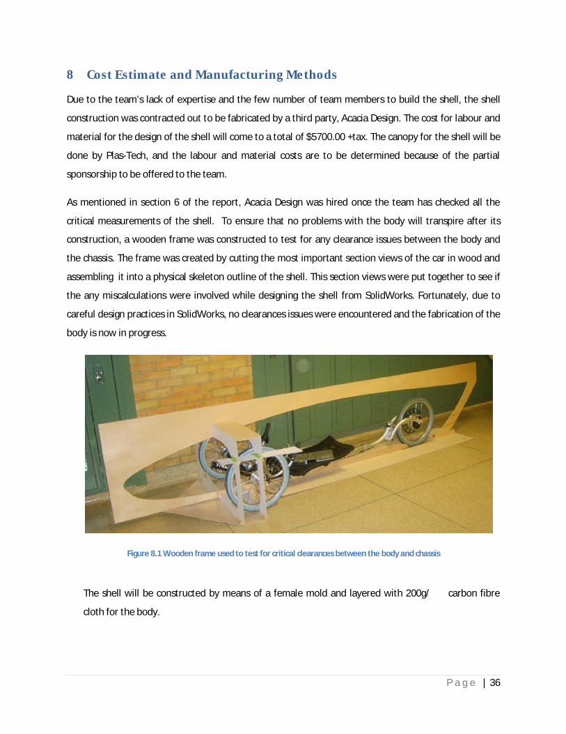
As mentioned in section 6 of the report, Acacia Design was hired once the team has checked all the
critical measurements of the shell. To ensure that no problems with the body will transpire after its
construction, a wooden frame was constructed to test for any clearance issues between the body and
the chassis. The frame was created by cutting the most important section views of the car in wood and
assembling it into a physical skeleton outline of the shell. This section views were put together to see if
the any miscalculations were involved while designing the shell from SolidWorks. Fortunately, due to
careful design practices in SolidWorks, no clearances issues were encountered and the fabrication of the
body is now in progress.
Figure 8.1 Wooden frame used to test for critical clearances between the body and chassis
The shell will be constructed by means of a female mold and layered with 200g/ � � � carbon fibre
cloth for the body.

P a g e | 37
This approach allows :
1) the dimensions of the body to be more accurately created
2) a more accurate mold to be created for the canopy
3) to allow teams in subsequent years to mold variations of the same body with a minimal of
effort.
The vehicle canopy will be molded out of either polycarbonate or acrylic plastic with a portion of the
female mold that was used to create the carbon fibre body. Detailed information regarding the
fabrication of the clear canopy can be found in section 6.
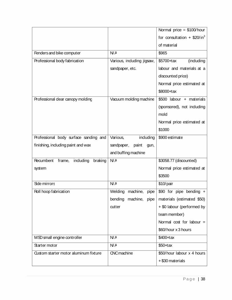
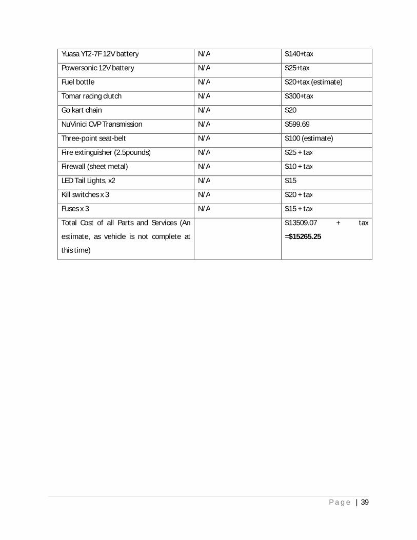
Machining processes used to fabricate/modify components on the vehicle included the following, as
well as cost of key vehicle components are listed below:
Table 8-1 Estimated Cost
Components Machining Tools Used Estimated Cost/Hour
Engine locating plate Drill press $0/hour labour + cost of
drill bits
Tubular steel seat modification Hacksaw $0 + cost of new blades
Re-boring of aluminum extension tube Lathe $40/hour labour for 1 hour
Construction of full-sized wooden frame
for body-chassis clearance test
Portable Jigsaw $60/hour labour + cost of
material for 6 hours
Custom free-wheel adapter for NuVinci
hub
CNC Machine $60/hour labour + cost of
material for 3 hours
Fitment of Custom sprocket for NuVinci
hub
Drill press $0 + cost of drill bits
Fitment of NuVinci hub to 20” wheel N/A $216.56 for labour
Printing of 3D scaled models for wind
tunnel testing
Dimension® 3D printer $118.00 for labour + cost
of materials (discounted
price: $0 labour + approx.
$7/in3 of material)
P a g e | 38
Normal price = $100/hour
for consultation + $20/in3
of material
Fenders and bike computer N/A $965
Professional body fabrication Various, including jigsaw,
sandpaper, etc.
$5700+tax (including
labour and materials at a
discounted price)
Normal price estimated at
$8000+tax
Professional clear canopy molding Vacuum molding machine $500 labour + materials
(sponsored), not including
mold
Normal price estimated at
$1000
Professional body surface sanding and
finishing, including paint and wax
Various, including
sandpaper, paint gun,
and buffing machine
$900 estimate
Recumbent frame, including braking
system
N/A $3058.77 (discounted)
Normal price estimated at
$3500
Side mirrors N/A $10/pair
Roll hoop fabrication Welding machine, pipe
bending machine, pipe
cutter
$90 for pipe bending +
materials (estimated $50)
+ $0 labour (performed by
team member)
Normal cost for labour =
$60/hour x 3 hours
MSD small engine controller N/A $400+tax
Starter motor N/A $50+tax
Custom starter motor aluminum fixture CNC machine $50/hour labour x 4 hours
+ $30 materials
P a g e | 39
Yuasa YTZ-7F 12V battery N/A $140+tax
Powersonic 12V battery N/A $25+tax
Fuel bottle N/A $20+tax (estimate)
Tomar racing clutch N/A $300+tax
Go kart chain N/A $20
NuVinici CVP Transmission N/A $599.69
Three-point seat-belt N/A $100 (estimate)
Fire extinguisher (2.5pounds) N/A $25 + tax
Firewall (sheet metal) N/A $10 + tax
LED Tail Lights, x2 N/A $15
Kill switches x 3 N/A $20 + tax
Fuses x 3 N/A $15 + tax
Total Cost of all Parts and Services (An
estimate, as vehicle is not complete at
this time)
$13509.07 + tax
=$15265.25
P a g e | 40
9 Driver Safety Features
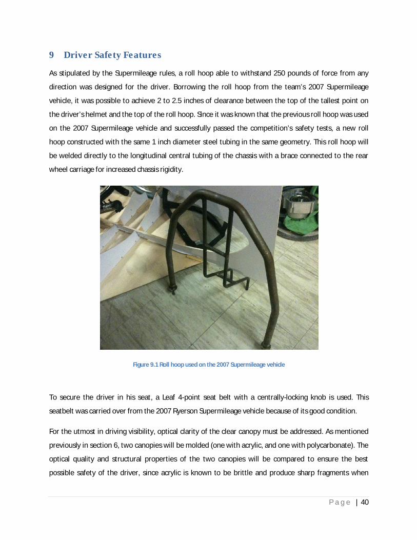
As stipulated by the Supermileage rules, a roll hoop able to withstand 250 pounds of force from any
direction was designed for the driver. Borrowing the roll hoop from the team’s 2007 Supermileage
vehicle, it was possible to achieve 2 to 2.5 inches of clearance between the top of the tallest point on
the driver’s helmet and the top of the roll hoop. Since it was known that the previous roll hoop was used
on the 2007 Supermileage vehicle and successfully passed the competition’s safety tests, a new roll
hoop constructed with the same 1 inch diameter steel tubing in the same geometry. This roll hoop will
be welded directly to the longitudinal central tubing of the chassis with a brace connected to the rear
wheel carriage for increased chassis rigidity.
Figure 9.1 Roll hoop used on the 2007 Supermileage vehicle
To secure the driver in his seat, a Leaf 4-point seat belt with a centrally-locking knob is used. This
seatbelt was carried over from the 2007 Ryerson Supermileage vehicle because of its good condition.
For the utmost in driving visibility, optical clarity of the clear canopy must be addressed. As mentioned
previously in section 6, two canopies will be molded (one with acrylic, and one with polycarbonate). The
optical quality and structural properties of the two canopies will be compared to ensure the best
possible safety of the driver, since acrylic is known to be brittle and produce sharp fragments when
P a g e | 41
impacted, but offers a higher relative optical clarity vs. polycarbonate. The company responsible for
molding the canopy have shown the team previous examples of their work, and the optical clarity of
similarly curved shapes were assessed to be very good.
To protect the driver’s head from injuries, a Simpson hard-shell racing helmet with a clear plastic visor
will be worn by the driver. This helmet was used in previous Supermileage competitions and is in good
condition for use by the driver for this year’s Supermileage event. The clear plastic visor was assessed,
and its distortion was deemed to be negligible when worn by the driver.
In the unlikely event of an engine fire, the driver will be able to actuate a fire extinguisher mounted in
his immediate vicinity. Flexible rubber tubing will be connected to the fire extinguisher and routed to
the engine compartment to distance the driver from the fire hazard. The fire extinguisher will be
securely mounted beneath the tubular steel seat to aid in lowering the car’s center of gravity for better
directional stability.
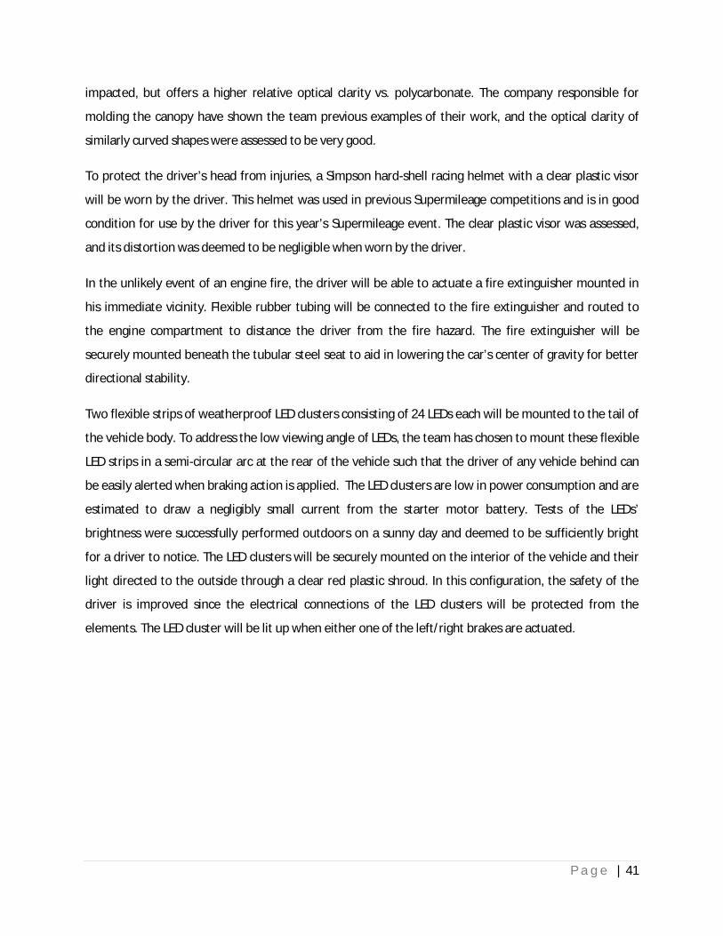
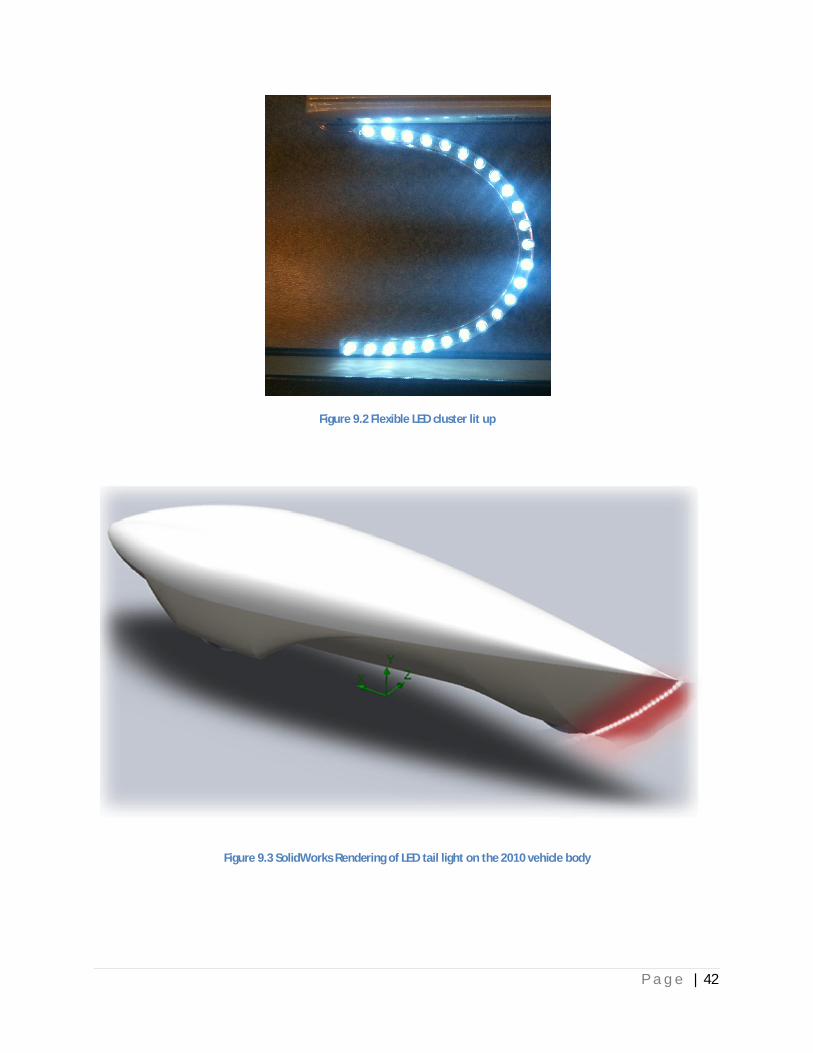
Two flexible strips of weatherproof LED clusters consisting of 24 LEDs each will be mounted to the tail of
the vehicle body. To address the low viewing angle of LEDs, the team has chosen to mount these flexible
LED strips in a semi-circular arc at the rear of the vehicle such that the driver of any vehicle behind can
be easily alerted when braking action is applied. The LED clusters are low in power consumption and are
estimated to draw a negligibly small current from the starter motor battery. Tests of the LEDs’
brightness were successfully performed outdoors on a sunny day and deemed to be sufficiently bright
for a driver to notice. The LED clusters will be securely mounted on the interior of the vehicle and their
light directed to the outside through a clear red plastic shroud. In this configuration, the safety of the
driver is improved since the electrical connections of the LED clusters will be protected from the
elements. The LED cluster will be lit up when either one of the left/right brakes are actuated.
P a g e | 42
Figure 9.2 Flexible LED cluster lit up
Figure 9.3 SolidWorks Rendering of LED tail light on the 2010 vehicle body
P a g e | 43
10 Appendix
Table 10-1 Engine Shaft to rear wheel sprocket gear ratio worksheet Part 1

P a g e | 44
Table 10-2 Engine Shaft to rear wheel sprocket gear ratio worksheet Part
P a g e | 45
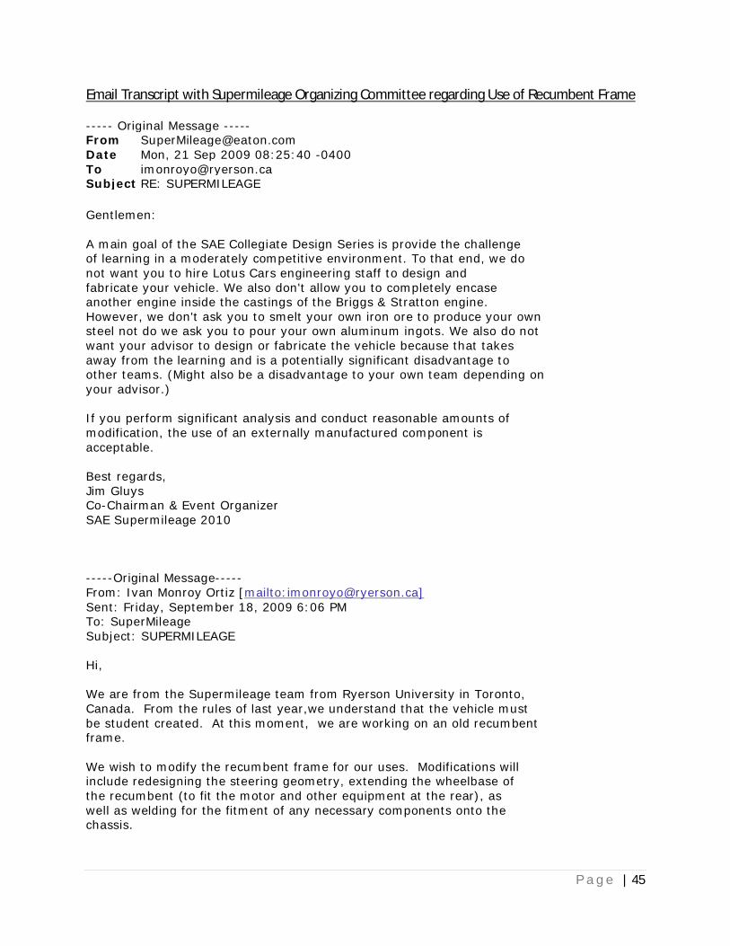
Email Transcript with Supermileage Organizing Committee regarding Use of Recumbent Frame
----- Original Message ----- From [email protected] Date Mon, 21 Sep 2009 08:25:40 -0400To [email protected] Subject RE: SUPERMILEAGE
Gentlemen: A main goal of the SAE Collegiate Design Series is provide the challenge of learning in a moderately competitive environment. To that end, we do not want you to hire Lotus Cars engineering staff to design and fabricate your vehicle. We also don't allow you to completely encase another engine inside the castings of the Briggs & Stratton engine. However, we don't ask you to smelt your own iron ore to produce your own steel not do we ask you to pour your own aluminum ingots. We also do not want your advisor to design or fabricate the vehicle because that takes away from the learning and is a potentially significant disadvantage to other teams. (Might also be a disadvantage to your own team depending on your advisor.) If you perform significant analysis and conduct reasonable amounts of modification, the use of an externally manufactured component is acceptable. Best regards, Jim Gluys Co-Chairman & Event Organizer SAE Supermileage 2010 -----Original Message----- From: Ivan Monroy Ortiz [mailto:[email protected]] Sent: Friday, September 18, 2009 6:06 PM To: SuperMileage Subject: SUPERMILEAGE Hi, We are from the Supermileage team from Ryerson University in Toronto, Canada. From the rules of last year,we understand that the vehicle must be student created. At this moment, we are working on an old recumbent frame. We wish to modify the recumbent frame for our uses. Modifications will include redesigning the steering geometry, extending the wheelbase of the recumbent (to fit the motor and other equipment at the rear), as well as welding for the fitment of any necessary components onto the chassis.

P a g e | 46
Is it possible to make use of a recumbent frame in this manner as a basis for our Supermileage design for the competition? Best regards, Ivan Monroy Ortiz & Charles Wong Co-Captains SM Ryerson Unversity
Related Documents