Design Report | 2015 Eklavya 4.0 AGV IIT Kharagpur Page 1 EKLAVYA 4.0 Indian Institute of Technology Kharagpur The Autonomous Ground Vehicle Research Group (Team AGV) Faculty Advisor: Dr. Debashish Chakravarty Email: [email protected] 1 Introduction Team Autonomous Ground Vehicle (AGV), under the ambit of Center for Robotics, IIT Kharagpur, has been pioneering the autonomous ground vehicle technology with the ultimate aim of developing the first self-driving car of India. The team hasbeen participating in IGVC since its inception in 2011 with the Eklavya series of vehicles. Eklavya 4.0, another feather in the cap of the Research Group is all set to participate in the 23rd Intelligent Ground Vehicle Competition (IGVC), Oakland University. With new robotic innovations, the successor of Eklavya 3.0, is a much more simplified and powerful Eklavya 4.0 in all aspects i.e mechanical, electrical and software. This report outlines the entire structure of Eklavya 4.0 listing out the innovations and improvements over the previous IGVC versions. 2 Team Organization The effort behind this project was put in by a bunch of over thirty enthusiastic and intellectual undergraduate students from various departments of IIT Kharagpur. This research group (AGV) works under the able guidance of Prof. Debashish Chakraborty, Department of Mining Engineering, IIT Kharagpur, along with five co- professor-in-charges namely Prof. D K Pratihar, Prof. P P Das, Prof. S K Pal, Prof Manoj Mondal and Prof M Sinha. The team is divided into seven major modules, namely Machine Learning, Computer Vision, Localization & SLAM, Control Systems, Motion Planning, Mechanical and Public-Relations. Figure 1. Team Organization

Welcome message from author
This document is posted to help you gain knowledge. Please leave a comment to let me know what you think about it! Share it to your friends and learn new things together.
Transcript
Design Report | 2015 Eklavya 4.0
AGV IIT Kharagpur Page 1
EKLAVYA 4.0Indian Institute of Technology Kharagpur
The Autonomous Ground Vehicle Research Group (Team AGV)Faculty Advisor: Dr. Debashish Chakravarty
Email: [email protected] Introduction
Team Autonomous Ground Vehicle (AGV), under the ambit of Center for Robotics, IITKharagpur, has been pioneering the autonomous ground vehicle technology with theultimate aim of developing the first self-driving car of India. The team has beenparticipating in IGVC since its inception in 2011 with the Eklavya series of vehicles.Eklavya 4.0, another feather in the cap of the Research Group is all set toparticipate in the 23rd Intelligent Ground Vehicle Competition (IGVC), OaklandUniversity. With new robotic innovations, the successor of Eklavya 3.0, is a muchmore simplified and powerful Eklavya 4.0 in all aspects i.e mechanical, electricaland software. This report outlines the entire structure of Eklavya 4.0 listing outthe innovations and improvements over the previous IGVC versions.
2 Team Organization
The effort behind this project was put in by a bunch of over thirty enthusiasticand intellectual undergraduate students from various departments of IIT Kharagpur.This research group (AGV) works under the able guidance of Prof. DebashishChakraborty, Department of Mining Engineering, IIT Kharagpur, along with five co-professor-in-charges namely Prof. D K Pratihar, Prof. P P Das, Prof. S K Pal, ProfManoj Mondal and Prof M Sinha. The team is divided into seven major modules,namely Machine Learning, Computer Vision, Localization & SLAM, Control Systems,Motion Planning, Mechanical and Public-Relations.
Figure 1. Team Organization
Design Report | 2015 Eklavya 4.0
AGV IIT Kharagpur Page 2
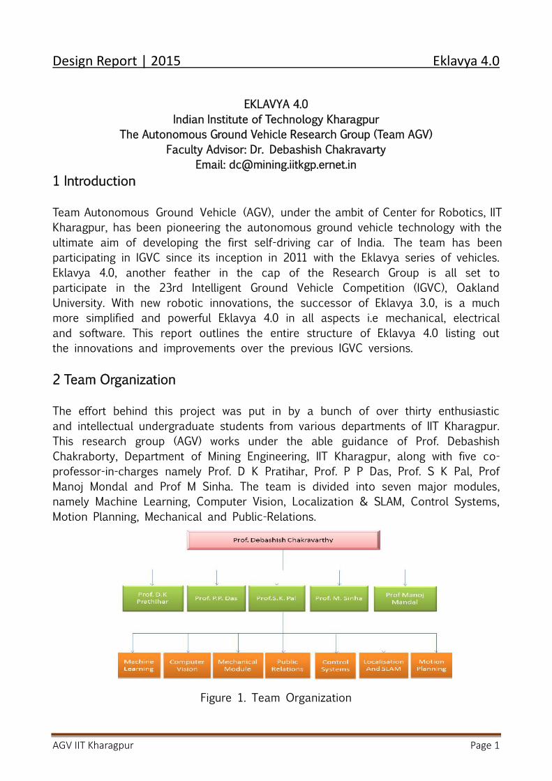
3 Mechanical Design
Figure 2. Eklavya 4.0 Chassis
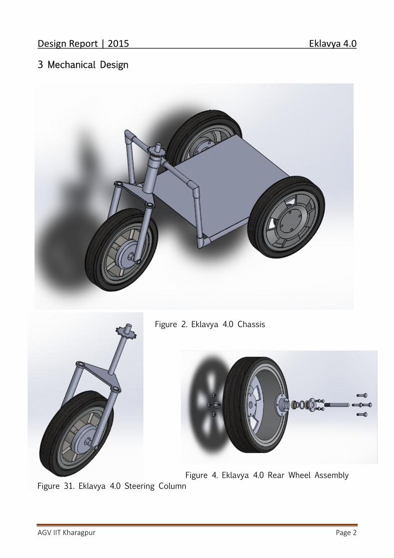
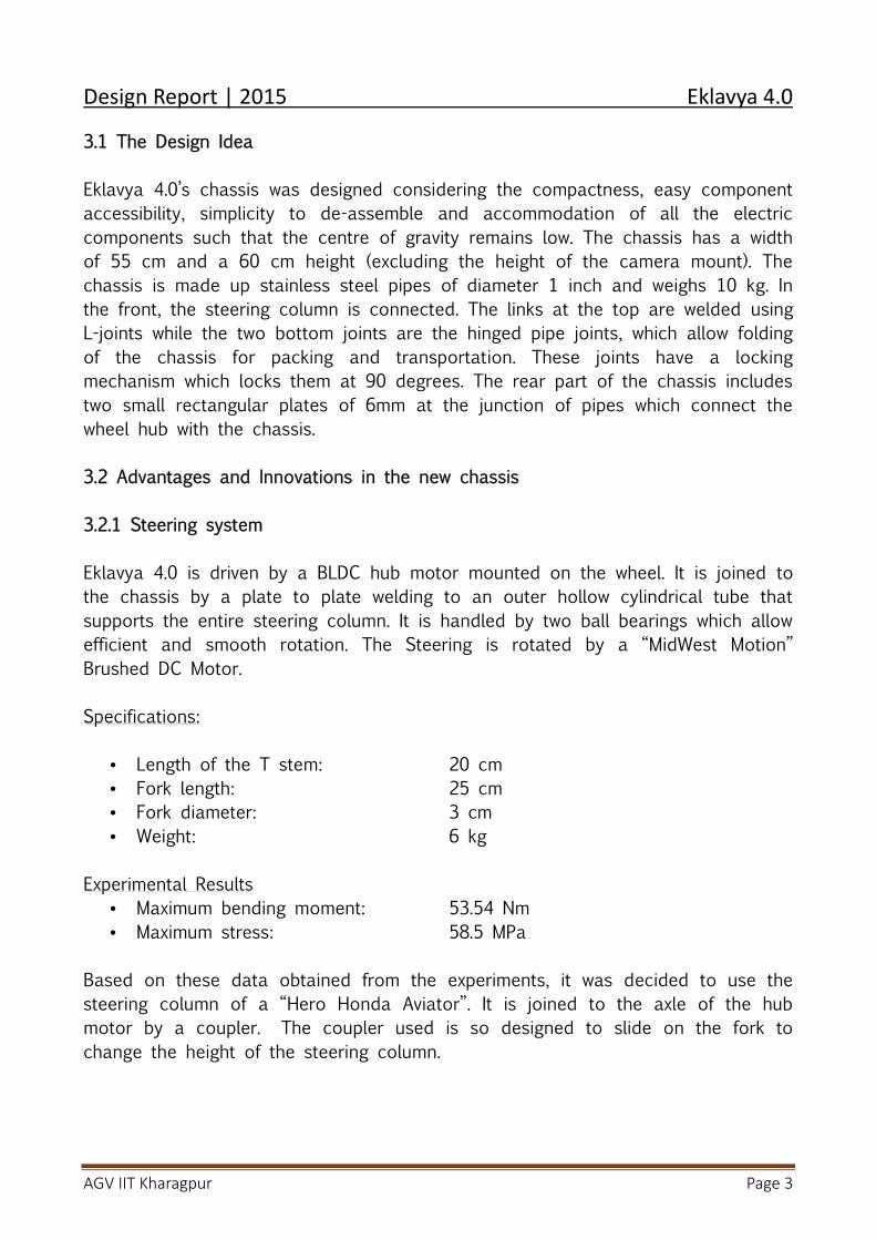
Figure 4. Eklavya 4.0 Rear Wheel AssemblyFigure 31. Eklavya 4.0 Steering Column
Design Report | 2015 Eklavya 4.0
AGV IIT Kharagpur Page 3
3.1 The Design Idea
Eklavya 4.0’s chassis was designed considering the compactness, easy componentaccessibility, simplicity to de-assemble and accommodation of all the electriccomponents such that the centre of gravity remains low. The chassis has a widthof 55 cm and a 60 cm height (excluding the height of the camera mount). Thechassis is made up stainless steel pipes of diameter 1 inch and weighs 10 kg. Inthe front, the steering column is connected. The links at the top are welded usingL-joints while the two bottom joints are the hinged pipe joints, which allow foldingof the chassis for packing and transportation. These joints have a lockingmechanism which locks them at 90 degrees. The rear part of the chassis includestwo small rectangular plates of 6mm at the junction of pipes which connect thewheel hub with the chassis.
3.2 Advantages and Innovations in the new chassis
3.2.1 Steering system
Eklavya 4.0 is driven by a BLDC hub motor mounted on the wheel. It is joined tothe chassis by a plate to plate welding to an outer hollow cylindrical tube thatsupports the entire steering column. It is handled by two ball bearings which allowefficient and smooth rotation. The Steering is rotated by a “MidWest Motion”Brushed DC Motor.
Specifications:
Length of the T stem: 20 cm Fork length: 25 cm Fork diameter: 3 cm Weight: 6 kg
Experimental Results Maximum bending moment: 53.54 Nm Maximum stress: 58.5 MPa
Based on these data obtained from the experiments, it was decided to use thesteering column of a “Hero Honda Aviator”. It is joined to the axle of the hubmotor by a coupler. The coupler used is so designed to slide on the fork tochange the height of the steering column.
Design Report | 2015 Eklavya 4.0
AGV IIT Kharagpur Page 4
Advantages
The complex chain and sprocket system is replaced by a single hub motor. Thecomplex differential drive control is replaced by the steering control which ismuch easier. It carries a BLDC hub motor with best mechanical efficiency. Thenew design allows better control to the robot compared to differential drive.
3.2.2 Wheel Drive
We had used Differential drive in our last vehicle but now we changed our drivemechanism from Differential to Steered drive method. There are many reasons forthis change. We used two different motors and a rear castor wheeled drive forstability but there were many unexpected errors in differential drive.
Disadvantages of Differential Drive:We had used a castor wheel drive in our old bot. This wheel used to get lock byitself frequently that disturbs the localization of the bot. Because of this locking,skidding takes place which also reduces friction in castor wheel. Sometimes itneeded a manual help to go back its original position. It takes more time tomake a turn because it slows down its speed while turning. These are thedisadvantages which makes us to change the driving mechanism from Differentialdrive to Steering drive.
Advantages of Steering Drive
The movement of vehicle is more precisely done by front steered control wheel.The two rear wheels are for support of the bot. There is no castor wheel whichreduces the risk of locking. Steering of front wheel is done by servo motor whichis connected to front wheel. Slipping of wheels is reduced resulting in constantmovement of bot.
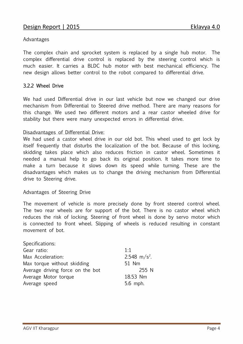
Specifications:Gear ratio: 1:1Max Acceleration: 2.548 m/s2.Max torque without skidding 51 NmAverage driving force on the bot 255 NAverage Motor torque 18.53 NmAverage speed 5.6 mph.
Design Report | 2015 Eklavya 4.0
AGV IIT Kharagpur Page 5
4. Electronics System
4.1 Flow of Information
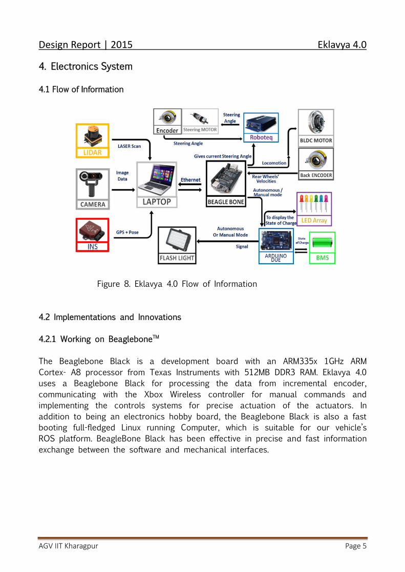
Figure 8. Eklavya 4.0 Flow of Information
4.2 Implementations and Innovations
4.2.1 Working on BeagleboneTM
The Beaglebone Black is a development board with an ARM335x 1GHz ARMCortex- A8 processor from Texas Instruments with 512MB DDR3 RAM. Eklavya 4.0uses a Beaglebone Black for processing the data from incremental encoder,communicating with the Xbox Wireless controller for manual commands andimplementing the controls systems for precise actuation of the actuators. Inaddition to being an electronics hobby board, the Beaglebone Black is also a fastbooting full-fledged Linux running Computer, which is suitable for our vehicle’sROS platform. BeagleBone Black has been effective in precise and fast informationexchange between the software and mechanical interfaces.
Design Report | 2015 Eklavya 4.0
AGV IIT Kharagpur Page 6
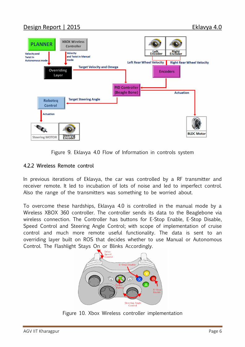
Figure 9. Eklavya 4.0 Flow of Information in controls system
4.2.2 Wireless Remote control
In previous iterations of Eklavya, the car was controlled by a RF transmitter andreceiver remote. It led to incubation of lots of noise and led to imperfect control.Also the range of the transmitters was something to be worried about.
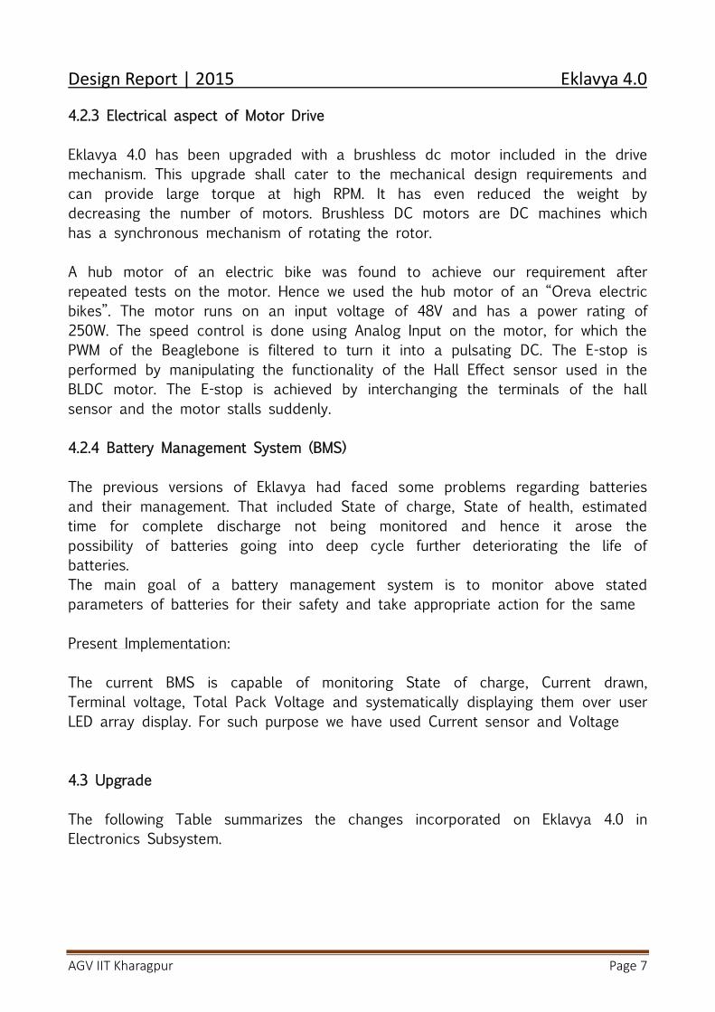
To overcome these hardships, Eklavya 4.0 is controlled in the manual mode by aWireless XBOX 360 controller. The controller sends its data to the Beaglebone viawireless connection. The Controller has buttons for E-Stop Enable, E-Stop Disable,Speed Control and Steering Angle Control; with scope of implementation of cruisecontrol and much more remote useful functionality. The data is sent to anoverriding layer built on ROS that decides whether to use Manual or AutonomousControl. The Flashlight Stays On or Blinks Accordingly.
Figure 10. Xbox Wireless controller implementation
Design Report | 2015 Eklavya 4.0
AGV IIT Kharagpur Page 7
4.2.3 Electrical aspect of Motor Drive
Eklavya 4.0 has been upgraded with a brushless dc motor included in the drivemechanism. This upgrade shall cater to the mechanical design requirements andcan provide large torque at high RPM. It has even reduced the weight bydecreasing the number of motors. Brushless DC motors are DC machines whichhas a synchronous mechanism of rotating the rotor.
A hub motor of an electric bike was found to achieve our requirement afterrepeated tests on the motor. Hence we used the hub motor of an “Oreva electricbikes”. The motor runs on an input voltage of 48V and has a power rating of250W. The speed control is done using Analog Input on the motor, for which thePWM of the Beaglebone is filtered to turn it into a pulsating DC. The E-stop isperformed by manipulating the functionality of the Hall Effect sensor used in theBLDC motor. The E-stop is achieved by interchanging the terminals of the hallsensor and the motor stalls suddenly.
4.2.4 Battery Management System (BMS)
The previous versions of Eklavya had faced some problems regarding batteriesand their management. That included State of charge, State of health, estimatedtime for complete discharge not being monitored and hence it arose thepossibility of batteries going into deep cycle further deteriorating the life ofbatteries.The main goal of a battery management system is to monitor above statedparameters of batteries for their safety and take appropriate action for the same
Present Implementation:
The current BMS is capable of monitoring State of charge, Current drawn,Terminal voltage, Total Pack Voltage and systematically displaying them over userLED array display. For such purpose we have used Current sensor and Voltage
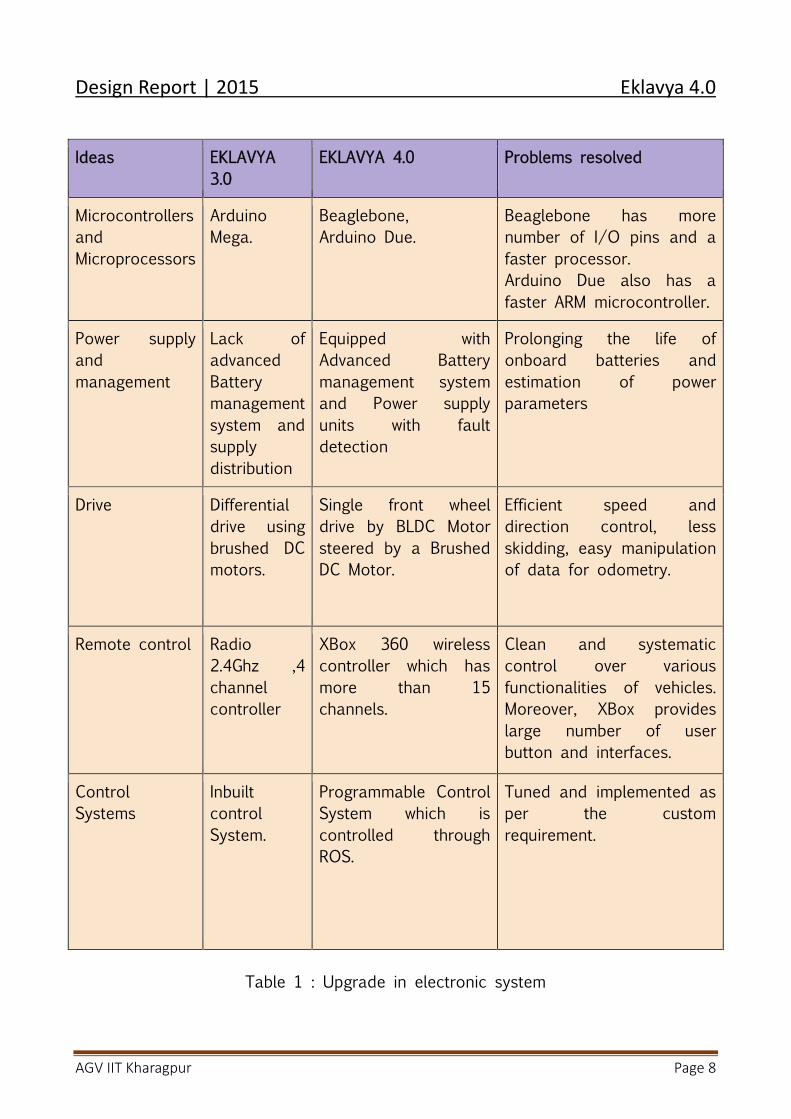
4.3 Upgrade
The following Table summarizes the changes incorporated on Eklavya 4.0 inElectronics Subsystem.
Design Report | 2015 Eklavya 4.0
AGV IIT Kharagpur Page 8
Ideas EKLAVYA3.0
EKLAVYA 4.0 Problems resolved
MicrocontrollersandMicroprocessors
ArduinoMega.
Beaglebone,Arduino Due.
Beaglebone has morenumber of I/O pins and afaster processor.Arduino Due also has afaster ARM microcontroller.
Power supplyandmanagement
Lack ofadvancedBatterymanagementsystem andsupplydistribution
Equipped withAdvanced Batterymanagement systemand Power supplyunits with faultdetection
Prolonging the life ofonboard batteries andestimation of powerparameters
Drive Differentialdrive usingbrushed DCmotors.
Single front wheeldrive by BLDC Motorsteered by a BrushedDC Motor.
Efficient speed anddirection control, lessskidding, easy manipulationof data for odometry.
Remote control Radio2.4Ghz ,4channelcontroller
XBox 360 wirelesscontroller which hasmore than 15channels.
Clean and systematiccontrol over variousfunctionalities of vehicles.Moreover, XBox provideslarge number of userbutton and interfaces.
ControlSystems
InbuiltcontrolSystem.
Programmable ControlSystem which iscontrolled throughROS.
Tuned and implemented asper the customrequirement.
Table 1 : Upgrade in electronic system
Design Report | 2015 Eklavya 4.0
AGV IIT Kharagpur Page 9
5. Perception
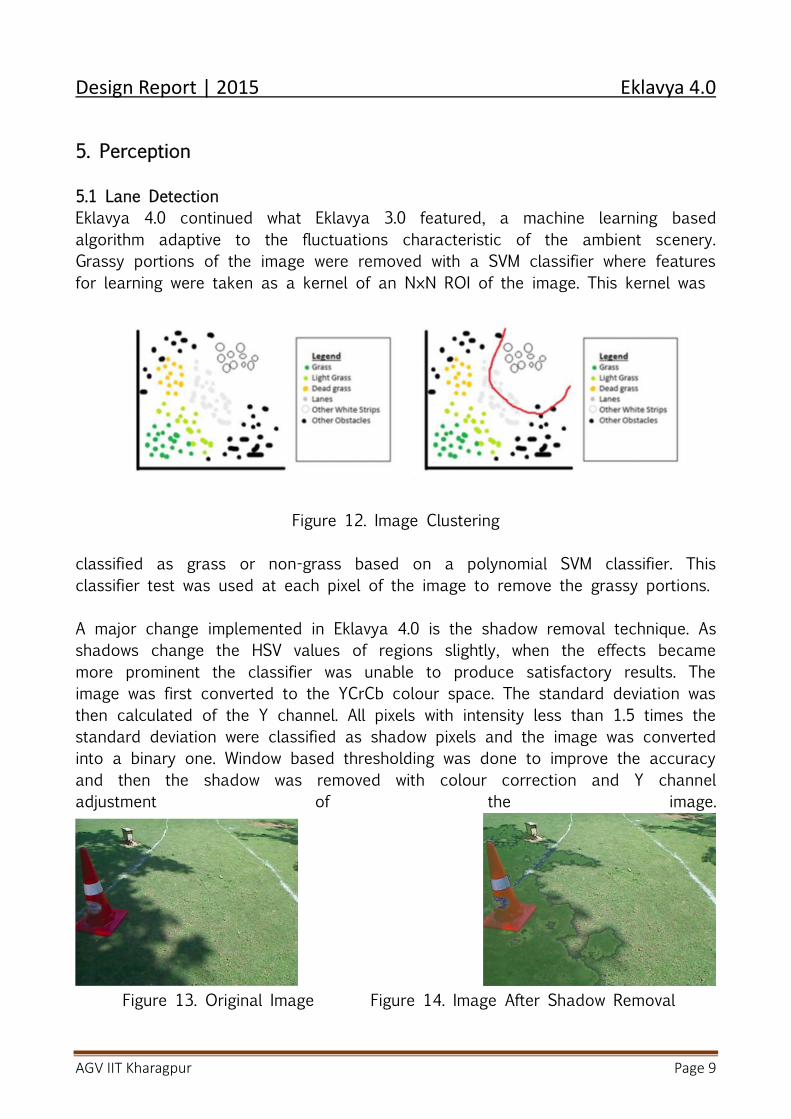
5.1 Lane DetectionEklavya 4.0 continued what Eklavya 3.0 featured, a machine learning basedalgorithm adaptive to the fluctuations characteristic of the ambient scenery.Grassy portions of the image were removed with a SVM classifier where featuresfor learning were taken as a kernel of an N×N ROI of the image. This kernel was
Figure 12. Image Clustering
classified as grass or non-grass based on a polynomial SVM classifier. Thisclassifier test was used at each pixel of the image to remove the grassy portions.
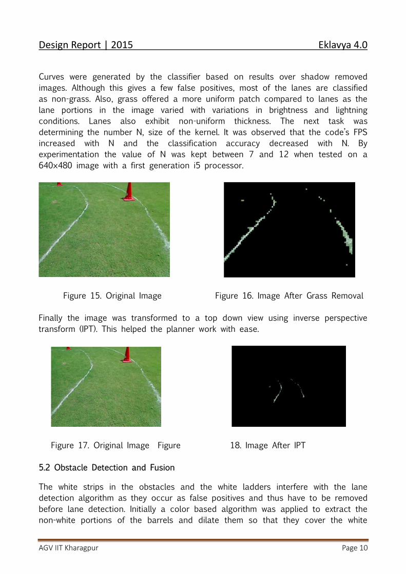
A major change implemented in Eklavya 4.0 is the shadow removal technique. Asshadows change the HSV values of regions slightly, when the effects becamemore prominent the classifier was unable to produce satisfactory results. Theimage was first converted to the YCrCb colour space. The standard deviation wasthen calculated of the Y channel. All pixels with intensity less than 1.5 times thestandard deviation were classified as shadow pixels and the image was convertedinto a binary one. Window based thresholding was done to improve the accuracyand then the shadow was removed with colour correction and Y channeladjustment of the image.
Figure 13. Original Image Figure 14. Image After Shadow Removal
Design Report | 2015 Eklavya 4.0
AGV IIT Kharagpur Page 10
Curves were generated by the classifier based on results over shadow removedimages. Although this gives a few false positives, most of the lanes are classifiedas non-grass. Also, grass offered a more uniform patch compared to lanes as thelane portions in the image varied with variations in brightness and lightningconditions. Lanes also exhibit non-uniform thickness. The next task wasdetermining the number N, size of the kernel. It was observed that the code’s FPSincreased with N and the classification accuracy decreased with N. Byexperimentation the value of N was kept between 7 and 12 when tested on a640×480 image with a first generation i5 processor.
Figure 15. Original Image Figure 16. Image After Grass Removal
Finally the image was transformed to a top down view using inverse perspectivetransform (IPT). This helped the planner work with ease.
Figure 17. Original Image Figure 18. Image After IPT
5.2 Obstacle Detection and Fusion
The white strips in the obstacles and the white ladders interfere with the lanedetection algorithm as they occur as false positives and thus have to be removedbefore lane detection. Initially a color based algorithm was applied to extract thenon-white portions of the barrels and dilate them so that they cover the white
Design Report | 2015 Eklavya 4.0
AGV IIT Kharagpur Page 11
strips lying in between them. Still, the problem prevailed in certain cases,especially with the white ladders. Thus, instead of a color based filter, the LIDARdata was used to erase parts of the image which coincided with the LIDARreadings. After this step, the image contained only the lanes and some randomnoise. The lane was further filtered by a color based threshold algorithm followedby an edge detection algorithm which resulted in high lane detection probabilitieswith very few false positives.
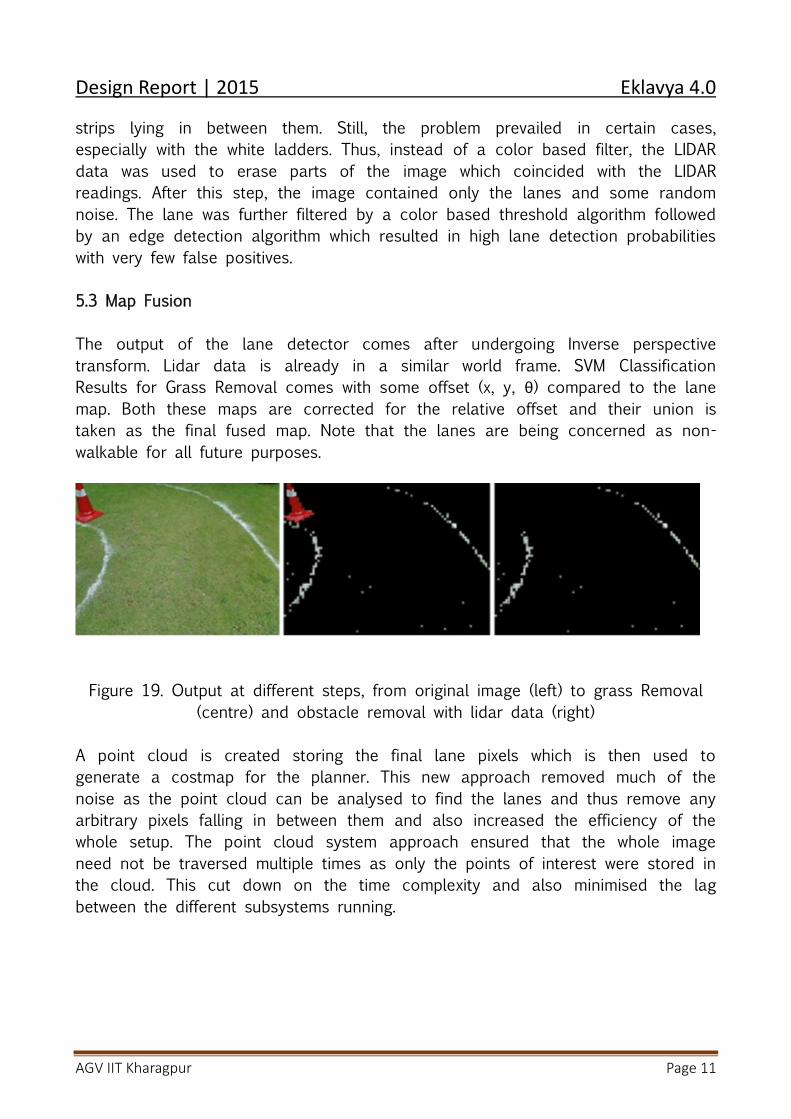
5.3 Map Fusion
The output of the lane detector comes after undergoing Inverse perspectivetransform. Lidar data is already in a similar world frame. SVM ClassificationResults for Grass Removal comes with some offset (x, y, θ) compared to the lanemap. Both these maps are corrected for the relative offset and their union istaken as the final fused map. Note that the lanes are being concerned as non-walkable for all future purposes.
Figure 19. Output at different steps, from original image (left) to grass Removal(centre) and obstacle removal with lidar data (right)
A point cloud is created storing the final lane pixels which is then used togenerate a costmap for the planner. This new approach removed much of thenoise as the point cloud can be analysed to find the lanes and thus remove anyarbitrary pixels falling in between them and also increased the efficiency of thewhole setup. The point cloud system approach ensured that the whole imageneed not be traversed multiple times as only the points of interest were stored inthe cloud. This cut down on the time complexity and also minimised the lagbetween the different subsystems running.
Design Report | 2015 Eklavya 4.0
AGV IIT Kharagpur Page 12
6. Planners
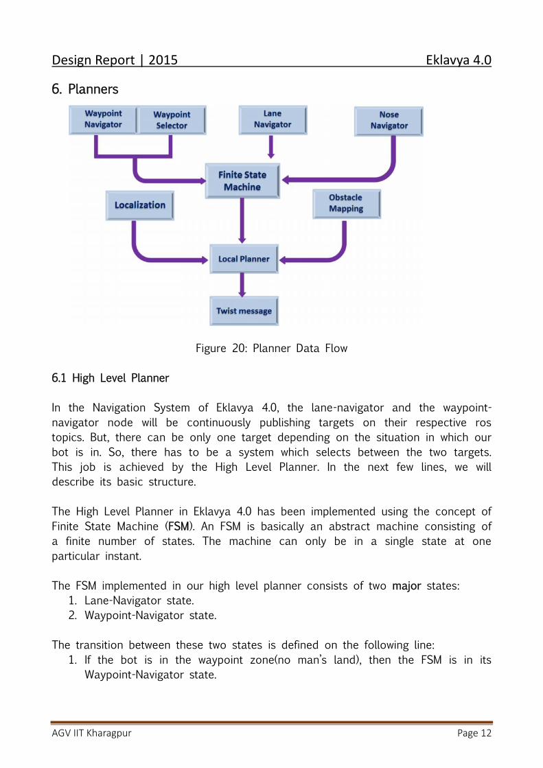
Figure 20: Planner Data Flow
6.1 High Level Planner
In the Navigation System of Eklavya 4.0, the lane-navigator and the waypoint-navigator node will be continuously publishing targets on their respective rostopics. But, there can be only one target depending on the situation in which ourbot is in. So, there has to be a system which selects between the two targets.This job is achieved by the High Level Planner. In the next few lines, we willdescribe its basic structure.
The High Level Planner in Eklavya 4.0 has been implemented using the concept ofFinite State Machine (FSM). An FSM is basically an abstract machine consisting ofa finite number of states. The machine can only be in a single state at oneparticular instant.
The FSM implemented in our high level planner consists of two major states:1. Lane-Navigator state.2. Waypoint-Navigator state.
The transition between these two states is defined on the following line:1. If the bot is in the waypoint zone(no man’s land), then the FSM is in its
Waypoint-Navigator state.
Design Report | 2015 Eklavya 4.0
AGV IIT Kharagpur Page 13
2. If the bot is not in no man’s land and can see the lanes, we make atransition to the Lane-Navigator state of the FSM.
Along with these states we have also incorporated the states for test andautonomous modes in our FSM implementation so as to take testing underconsideration.The most important advantage of implementing FSM in Eklavya 4.0 is that it ispossible to incorporate certain other special cases in the high level plannerwithout disturbing the earlier structure.
6.2 Global PlannerThe Global planner is responsible for generating a high level plan for thenavigation stack to follow. Given a goal that is arbitrarily far away from the robot,the Global planner will create a series of waypoints for the local planner toachieve.
The current implementation of the navigation stack uses a grid-based Globalplanner that assumes the robot is circular in shape and it produces waypointsfor the robot that are optimistic for the actual robot footprint, and may in-fact beinfeasible.The Global planner takes in sensor data in the form of point-cloud messages andLIDAR data in the form of laser-scan messages it uses these information to createthe Global costmap. The static map layer represents a largely unchanging portionof the costmap, like those generated by SLAM.
If the bot is in Waypoint navigation mode then our Global path planner plans asequence of the waypoints in two ways:-
1. It first goes to the nearest waypoint and then continues traversing all thewaypoints in the least distance order.
2. It first plans a path so that it can traverse all the waypoints by coveringthe minimum distance by using the greedy algorithm.
Then the Global planner checks if the robot has reached the target or not. It getsthis information from two ways:-
1. It checks the local planner status if it has reached the goal or not.2. It checks if the GPS coordinates of the robot is within a threshold distance
from the goal or not.If the robot is unable to reach the target then the Global planner switches torecovery mode and does either of the following:-clear_costmap_recovery - A recovery behavior that reverts the costmaps used bymove_base to the static map outside of a user-specified range
Design Report | 2015 Eklavya 4.0
AGV IIT Kharagpur Page 14
rotate_recovery - a recovery behavior that performs a 360 degree rotation of therobot to attempt to clear out space.
Then after this Global planner informs the High-level planner if it has reached thegoal or not and waits till the High-level planner gives the next target.
6.3 Local Planner
Base local planner provides a controller connecting the robot with theplanner.
Like the global planner, local planner creates a value function in the formof a grid called cost-map calculating the costs of traversing the cells of thegrids.
The controller using the cost-map of the planner sends the direction oftraversal and velocity to the bot.
The principle of local planning is the search for a suitable local plan inevery control cycle. For that purpose, a number of candidate trajectoriesare generated. For a generated trajectory, it is checked whether itcollides with an obstacle. If not, a rating is given to compare severaltrajectories picking the best.
Two types1. Trajectory Roller2. Dynamic Window Approach
The basic idea of both the Trajectory Rollout and Dynamic Window Approach(DWA) algorithms is as follows:
1. Discrete values of the bot’s movement parameters are taken and it issimulated to check the trajectory possibilities that may arise.
2. Then each such possibility is evaluated on the basis of :- proximity toobstacles, proximity to the goal, proximity to the global path, and speedand a score is assigned to each trajectory possibility.
3. The highest scoring trajectory is chosen and is passed to the bot forexecution and this is repeated.
We have preferred DWA over TR since it samples from stepwise achievablevelocities (given max acc.) whereas TR samples over the set of achievablevelocities (given max acc.) over the entire forward simulation.
Design Report | 2015 Eklavya 4.0
AGV IIT Kharagpur Page 15
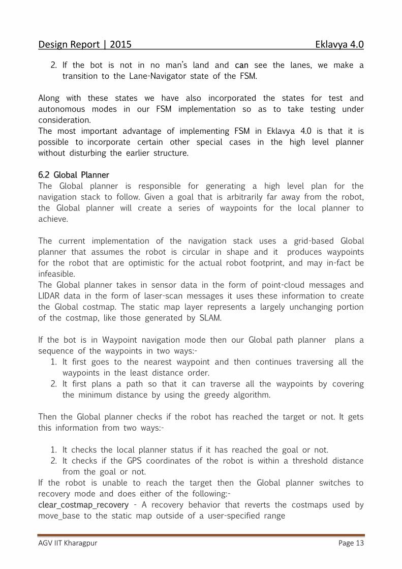
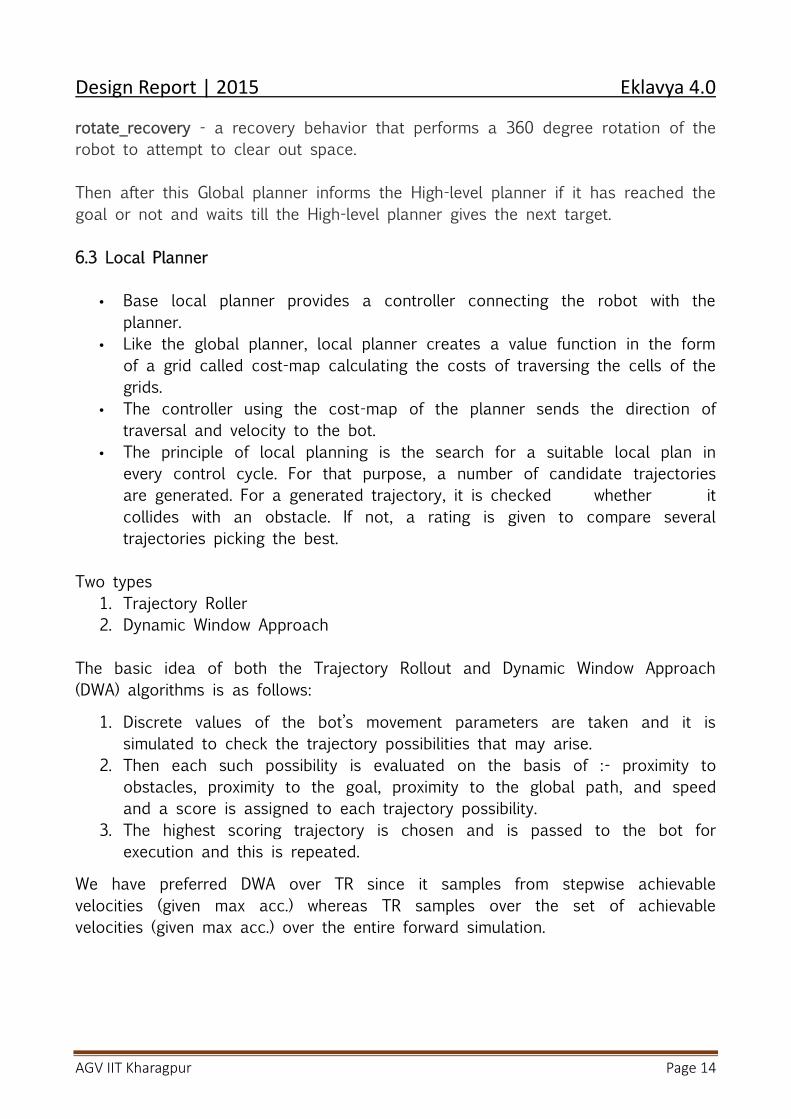
Figure 21: Occupancy Grid from LIDAR
Costmap In a particular situation, the decision of path to be chosen is taken by first
forming the intersection of global and local cost map. The move_base node maintains the common cost map and implements the
global navigation tasks. Costmap is made using a decay function by allocating values to the points
following the rule:- the region closest to the obstacle will be allotted thegreatest value and the area where there is practically no effect of theobstacle will be allotted the lowest value.
Since the bot is considered a point object, the region enclosing the objectwith a radius of the bot is allocated substantially high values than the restof the costmap.
The points that do not qualify in either of the above cases are decided onthe basis of other factors.
7. Localization
One of the most important requirement for automating a robot is its localization.By localization, we mean that the robot must, all times, have a fairly accurateidea about its position in a given map or environment. If a robot does not knowwhere it is, it cannot decide what to do next. In order to localize itself, a robothas to have access to relative and absolute measurements that containinformation related to its position. The robot gets this information from its
Design Report | 2015 Eklavya 4.0
AGV IIT Kharagpur Page 16
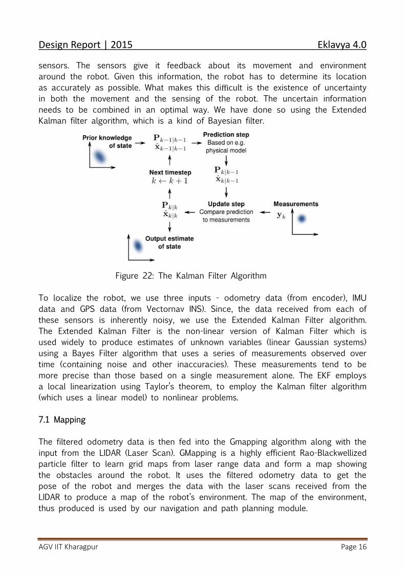
sensors. The sensors give it feedback about its movement and environmentaround the robot. Given this information, the robot has to determine its locationas accurately as possible. What makes this difficult is the existence of uncertaintyin both the movement and the sensing of the robot. The uncertain informationneeds to be combined in an optimal way. We have done so using the ExtendedKalman filter algorithm, which is a kind of Bayesian filter.
Figure 22: The Kalman Filter Algorithm
To localize the robot, we use three inputs - odometry data (from encoder), IMUdata and GPS data (from Vectornav INS). Since, the data received from each ofthese sensors is inherently noisy, we use the Extended Kalman Filter algorithm.The Extended Kalman Filter is the non-linear version of Kalman Filter which isused widely to produce estimates of unknown variables (linear Gaussian systems)using a Bayes Filter algorithm that uses a series of measurements observed overtime (containing noise and other inaccuracies). These measurements tend to bemore precise than those based on a single measurement alone. The EKF employsa local linearization using Taylor’s theorem, to employ the Kalman filter algorithm(which uses a linear model) to nonlinear problems.
7.1 Mapping
The filtered odometry data is then fed into the Gmapping algorithm along with theinput from the LIDAR (Laser Scan). GMapping is a highly efficient Rao-Blackwellizedparticle filter to learn grid maps from laser range data and form a map showingthe obstacles around the robot. It uses the filtered odometry data to get thepose of the robot and merges the data with the laser scans received from theLIDAR to produce a map of the robot’s environment. The map of the environment,thus produced is used by our navigation and path planning module.
Design Report | 2015 Eklavya 4.0
AGV IIT Kharagpur Page 17
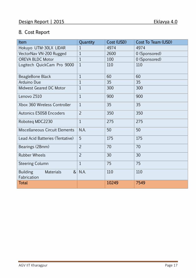
8. Cost Report
Item Quantity Cost (USD) Cost To Team (USD)Hokuyo UTM-30LX LIDAR 1 4974 4974VectorNav VN-200 Rugged 1 2600 0 (Sponsored)OREVA BLDC Motor 1 100 0 (Sponsored)Logitech QuickCam Pro 9000 1 110 110
BeagleBone Black 1 60 60Arduino Due 1 35 35Midwest Geared DC Motor 1 300 300
Lenovo Z510 1 900 900
Xbox 360 Wireless Controller 1 35 35
Autonics E50S8 Encoders 2 350 350
Roboteq MDC2230 1 275 275
Miscellaneous Circuit Elements N.A. 50 50
Lead Acid Batteries (Tentative) 5 175 175
Bearings (28mm) 2 70 70
Rubber Wheels 2 30 30
Steering Column 1 75 75
Building Materials &Fabrication
N.A. 110 110
Total 10249 7549

Design Report | 2015 Eklavya 4.0
AGV IIT Kharagpur Page 18
Related Documents