BHAVINI BHAVINI KALPAKKAM KALPAKKAM Design Provisions for Design Provisions for Core Instrumentation of PFBR Core Instrumentation of PFBR C. Paramasivan Pillai Indo-French Technical Seminar, France, 3 rd – 8 th April 2006.

Welcome message from author
This document is posted to help you gain knowledge. Please leave a comment to let me know what you think about it! Share it to your friends and learn new things together.
Transcript

BHAVINIBHAVINIKALPAKKAMKALPAKKAM
Design Provisions for Design Provisions for
Core Instrumentation of PFBRCore Instrumentation of PFBR
C. Paramasivan Pillai
Indo-French Technical Seminar, France, 3rd – 8th April 2006.

The core instrumentation system consists of
Neutron Flux Monitoring System
Core Temperature Monitoring System
Flow Monitoring System
Failed Fuel Detection System
Design provision for core instrumentation of PFBR
The functions of the system are
To monitor the core status in all states of the reactor –
shutdown, fuel handling, start-up, intermediate & power
ranges and during design basis events.To detect errors during fuel handling
Type and Location of Neutron Detectors
The neutron flux around the reactor is very low as neutron
shields are provided to protect the components housed inside
the main vessel and to reduce the secondary sodium activity.
NEUTRON FLUX MONITORING

The neutron flux (total) at core centre varies from
1.7x10⁷ nv (n/cm2/s) at shutdown to 8x10¹⁵ nv at
nominal power.
The neutron flux at the control plug location varies
from 6nv (with auxiliary neutron source) to 2.7x10⁹ nv
(U235 equivalent thermal flux) from shutdown to nominal
power.
The neutron flux at the under vessel location varies
from 1.1x10⁻⁵ nv to 2x10⁵ nv (U235 equivalent thermal
flux).
NEUTRON FLUX MONITORING

NEUTRON FLUX MONITORING
Detectors under vessel for power operation
Detectors in central subassembly
Six high temperature fission chambers during startup and intermediate operation (3 safety, 2 control, 1 insitu spare)

Detectors for Normal Operation
It is proposed to provide 6 (3 for safety, 2 for control and 1 insitu spare) high temperature fission chambers at 3 locations 120o apart in the control plug
These detectors facilitate monitoring the measurement range from shutdown to intermediate power range with wide range channels having pulse, Campbell modes from 1 nv to 3.1 x 10⁷ nv.
NEUTRON FLUX MONITORING

NEUTRON FLUX MONITORING

Above 1% power, the response time and accuracy of the control plug detectors in campbell and dc modes of operation are not meeting the requirements due to leakage and gamma currents.
Hence 6 fission chambers of sensitivity 0.2 cps/nv working in pulse mode (3 for safety, 2 for control and one in-situ spare) are proposed to be placed under the safety vessel with concrete over the detectors removed for better flux availability during power range.
NEUTRON FLUX MONITORING

NEUTRON FLUX MONITORING

NEUTRON FLUX MONITORING
1.7x10⁷
8x101515 16x1015
25 166 2160 92.7x10 5.4x10⁹
3.6 Wt 15 Wt 100 Wt 1 kWt 10 kWt 100 kWt 1 MWt 10 MWt 100 MWt 1000 1250 1500 2500MWt MWt MWt MWt
NOMINAL POWER (Pn) SHUTDOWN
POWER
CORE CENTRE FLUX
FLUX AT CP DETECTOR LOCATION
CRITICALITYat 144 cps
1 100 1000 10 10 104 5 6
2x10 cps6
PULSE MODE
25 kWt 250 kWt 2.5 MWt 25 MWt 250 MWt 2500 MWt
CAMPBELL MODE
PULSE MODE(LINEAR)
ABSOLUTE POWER TRIPLin N at 110% Pn
(1375 MWt)
TRIP ON CAMPBELL CHANNELS,Log P at 20% Pn (250 MWt)
INTERLOCK ON TAKE OVER OF Lin PCHANNELS FROM CAMPBELLCHANNELS, Lin N1-IL at 5% Pn
(62.5 MWt)
TRIP ON PULSE CHANNELS,Log N at 800 kWt (10 cps)6
INTERLOCK ON TAKE OVER OF CAMPBELLCHANNELS FROM PULSE CHANNELS,
Log P1-IL at 200 kWt
NON-AVAILIBILITY OF ADEQUATENEUTRONS, Log No at 3 cps
FUEL LOADING INTERLOCK,Log N1-IL at 25 cps
HTFC(0.2 cps/nv)WITH WIDE
150 MWt 1500 MWt(120% Pn)
RANGE CHANNEL
6 2.16x10⁴ 5 6 7 8 9
7 8 9 10 11 12 13 14 15
U THERMAL EQUIVALENT FLUX235
9.6x10
NEUTRON FLUX MONITORING - SAFETY CHANNELS -NORMAL OPERATION
*
7.1x10 4.7x10 6.4x10 6.4x10 6.4x10 6.4x10 6.4x10 6.4x10 6.4x10
2.16x10 2.16x10 2.16x10 2.16x10 2.16x10(nv)
(nv)
3.24x10⁹
(k = 0.93)eff
15 MWt
(BOEC CORE, WITH SOURCE)
(0.2 cps/nv)UNDER VESSEL
FISSION CHAMBER
101.2
FLUX AT UV DETECTOR LOCATION* (nv) 2x102x103 4 1.66x1052x105
3.3x10⁵
Requirement of source
During the first 4 fuel cycles, before the BOEC (Beginning of Equilibrium Cycle) is achieved, the shutdown count rates on control plug location are very less. It is planned to load source subassemblies containing fresh Antimony Berilium pins during first startup.
These source assemblies get activated during reactor operation during first fuel cycle and provide a min. shutdown countrate of 6 cps on control plug detectors after 4 months of operation.
NEUTRON FLUX MONITORING

Till the source gets activated a special instrumentation namely Instrumented Central Sub Assembly (ICSA) monitors the core during shutdown and startup.
The ICSA contains 3 high temperature fission chambers of 0.1 cps/nv connected to pulse counting channels for monitoring flux and provides trips in the range from 10 nv to 107 nv (Core centre, U 235 thermal equivalent flux) (~2 kWt).
NEUTRON FLUX MONITORING

NEUTRON FLUX MONITORING
3 fission chambers in ICSA for flux monitoring during core loading and low power

The detectors in control plug takes over safety and control action from the ICSA detectors arond ~103 nv at control plug location well before the ICSA detectors saturate. As the power goes up the ICSA is withdrawn and kept at a higher elevation at ~ 1 kWt power.
In case of long shutdown extending more than 4 months during reactor operation , the shutdown count rate goes < 3 cps as the source decays with a half-life of 60 days, The subsequent reactor startup is done again with ICSA, till the source gets reactivated.
NEUTRON FLUX MONITORING

NEUTRON FLUX MONITORING
1.7x1078x10
151516x10
15
25 166 21609
2.7x105.4x109
3.6 Wt 15 Wt 100 Wt 1 kWt 10 kWt 100 kWt 1 MWt 10 MWt 100 MWt 1000 1250 1500 2500MWt MWt MWt MWt
NOMINAL POWER (Pn) SHUTDOWN
POWER
CORE CENTRE FLUX
FLUX AT CP DETECTOR LOCATION
CRITICALITYat 144 cps
1 100 1000 10 10 104 5 62x10 cps
6
PULSE MODE
NON-AVAILIBILITY OF ADEQUATE NEUTRONS
FUEL LOADING INTERLOCK,Log N1-IL at 25 cps
HTFC(0.2 cps/nv)WITH WIDE
RANGE CHANNEL
6 2.16x10⁴ 5 6 7 8 9
7 8 9 10 11 12 13 14 15
U THERMAL EQUIVALENT FLUX235
9.6x10
NEUTRON FLUX MONITORING - SAFETY CHANNELS
*
7.1x10 4.7x10 6.4x10 6.4x10 6.4x10 6.4x10 6.4x10 6.4x10 6.4x10
2.16x10 2.16x10 2.16x10 2.16x10 2.16x10(nv)
(nv)
3.24x10⁹
(k = 0.93)eff
10
2x10 cps6
610105104100010010
PULSE MODE
PULSE WITH
(0.1cps/nv)HTFC
CHANNEL
NON-AVAILABILITY OF
ADEQUATE NEUTRONS TRIP ON PULSE CHANNELS,
Log C at 10 cps (~ 2 kWt)Log Co at 3 cps
IL ON TAKE OVER OF CP DETECTORSFROM ICSA CHANNELS
Log N2-IL at 200 cps
6
IN ICSA
1.2
(ICSA AND SOURCE RANGE)
Log No at 3 cps

Design Basis Events (DBE)
For the following DBE, Neutron Flux monitoring system initiates automatic safety action.
Transient over power at low powerTransient over power at start-up, Transient over power at power operationShort period during power raiseAbnormal reactivity changes
NEUTRON FLUX MONITORING

Functions Monitor the temperatures at the outlets of FSA and core
inlets Derive parameters such as the
Mean core outlet temperature (M), Mean temperature rise in the core (M) Deviation in individual subassembly sodium outlet
temperature over the expected value (I). To provide SCRAM signals on
Central sub assembly temperature (CSA) Mean temperature rise in the core (M) Deviation in individual subassembly sodium outlet
temperature over the expected value (I). Core inlet temperature (RI)
CORE TEMPERATURE MONITORING SYSTEM

Specification Thermocouple type: K type (Chromel-Alumel) Mineral
insulated, SS sheathed, ungrounded T/C Size : 1 mm. Sensitivity : 41 V / K Range : 400 to 1100 K Overall accuracy : 3 K Time constant : 300 ms (for the TC for CSA)
: 62 s (for the TC for other FSA)
Scan interval : 1 Sec.
CORE TEMPERATURE MONITORING SYSTEM

Signal Processing Central Sub-assembly outlet and core inlet sodium
temperature signals are triplicated and processed by hardwired electronics
For all other fuel sub-assemblies sodium outlet temperature is monitored with 2 T/C (in thermowell) and each T/C signal is triplicated after signal conditioning and processed by 3 different Real Time Computers (RTC)
CORE TEMPERATURE MONITORING SYSTEM

Central SA Outlet Sodium Temperature Measurement
TC are located on the central canal plug - directly
in contact with sodium
Signals are processed by hardwired electronics
SCRAM signal is generated through 2/3 logic.
Connected to the RTC for calculating
Mean core outlet temperature (M)
Deviation in individual subassembly sodium outlet
temperature over the expected value (I)
CORE TEMPERATURE MONITORING SYSTEM

CORE TEMPERATURE MONITORING SYSTEM
Thermocouple in central canal plug

2 /
3 L
OG
IC
SCU
SCU
SCU
Central Sub-assembly Outlet Sodium Temperature Monitoring System
TCs in Central canal plug
CR
CORE TEMPERATURE MONITORING SYSTEM

FSA Outlet Sodium Temperature Measurement
Two TC in thermowells at the outlets of each SA (except central sub assembly).
RTC calculates M, M, I
RTC initiates SCRAM on M
and I For calculating M and I,
Minimum of the Two RI is taken as RI for calculation
SCRAM on I is not effective when (csa - RI )below a setpoint
CORE TEMPERATURE MONITORING SYSTEM

CORE TEMPERATURE MONITORING SYSTEM

TC – A210 Nos.
RTC-A
RTC-B
RTC-CRCB Side
-RI-1B, -RI-2B, -CSA-B
-RI-1A, -RI-2A, -CSA-A
-RI-1C, -RI-2C, -CSA-C
2 /
3 L
OG
IC
FSA Outlet sodium Temperature Monitoring System
CORE TEMPERATURE MONITORING SYSTEM
ISO AMP
ISO AMP
ISO AMP
ISO AMP
TC – B210 Nos.
ISO AMP
ISO AMP
ISO AMP
ISO AMP

Fig. 1 : LOCATION OF EDDY CURRENT FLOW METERS IN PUMPS
Thermocouple Probes
CORE TEMPERATURE MONITORING SYSTEM
A A
Detail-A

Thermocouple Probe Location
CORE TEMPERATURE MONITORING SYSTEM
EL. 22740
THERMOCOUPLEPROBE
PUMP SUCTION
Thermocouple Probe
EL. 22740
PSP suction
Reactor Inlet Temperature Monitoring System

Thermocouple Probe
CORE TEMPERATURE MONITORING SYSTEM
GRIPPER
GUIDE RING
SEAL PLUG
CONNECTOR
2-THERMOCOUPLES
EXTENSION
INTERMEDIATE
TUBE Ø4/5
Ø1mm
PIECE
Reactor Inlet Temperature Monitoring System

Reactor Inlet Temperature Monitoring System
2 /
3 L
OG
IC
SCU
SCU
SCU
2 /
3 L
OG
IC
SCU
SCU
SCU
TCs in PSP-1
TCs in PSP-2
CR BCR
CORE TEMPERATURE MONITORING SYSTEM
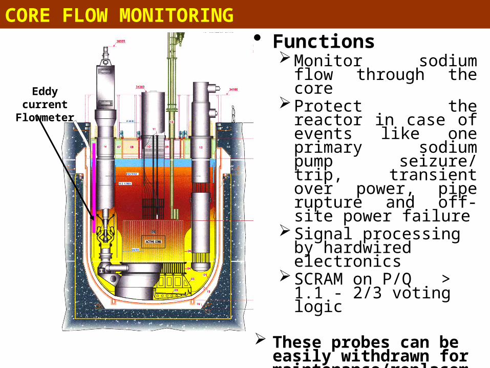
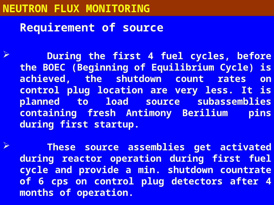
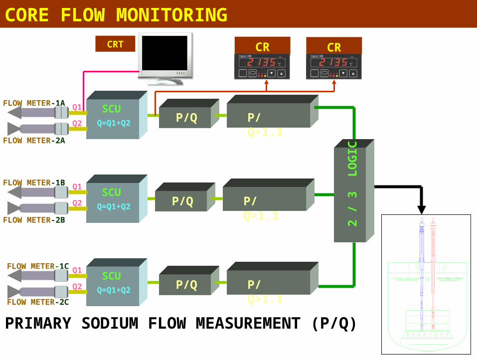
Eddy current Flowmeter
Functions Monitor sodium flow
through the core Protect the reactor in
case of events like one primary sodium pump seizure/ trip, transient over power, pipe rupture and off-site power failure
Signal processing by hardwired electronics
SCRAM on P/Q > 1.1 - 2/3 voting logic
These probes can be easily withdrawn for maintenance/replacement
CORE FLOW MONITORING
P/Q>1.1FLOW METER-1A
FLOW METER-2A
2 /
3 L
OG
IC
FLOW METER-1B
FLOW METER-2B
FLOW METER-1C
FLOW METER-2C
P/Q
P/Q
P/Q
P/Q>1.1
P/Q>1.1
SCUQ=Q1+Q2
CR
PRIMARY SODIUM FLOW MEASUREMENT (P/Q)
SCUQ=Q1+Q2
Q1
Q2
Q1
Q2
SCUQ=Q1+Q2
Q1
Q2
CRCRT
CORE FLOW MONITORING
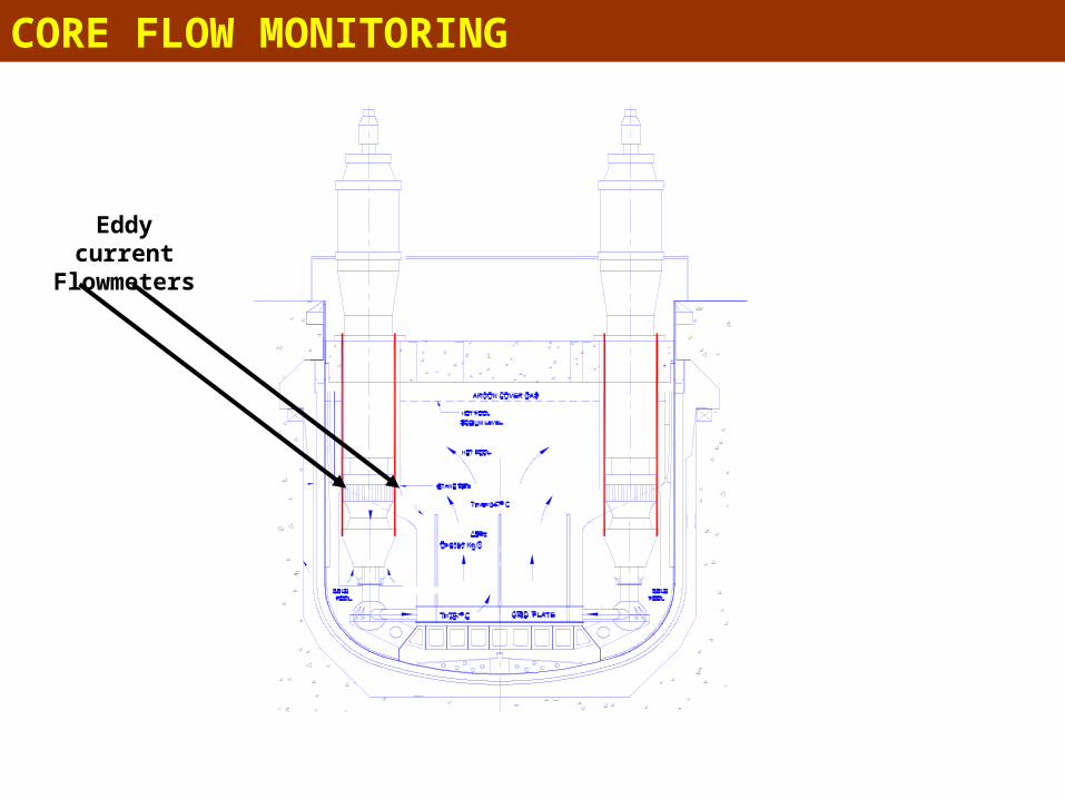
Fig. 1 : LOCATION OF EDDY CURRENT FLOW METERS IN PUMPS
Eddy current Flowmeters
CORE FLOW MONITORING
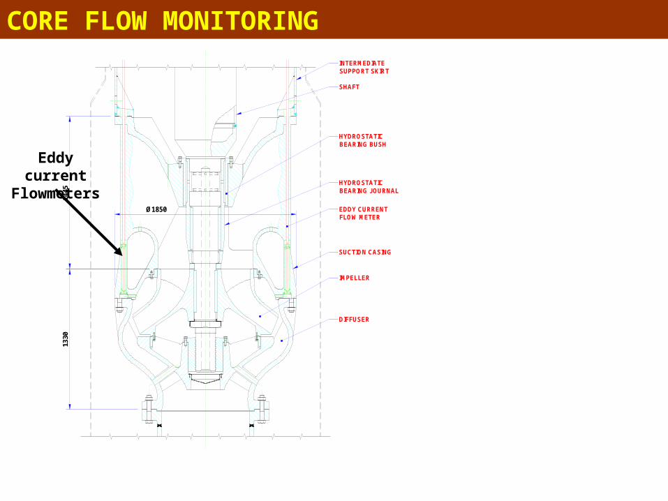
Ø1850
1330
1445
INTERMEDIATE SUPPORT SKIRT
SHAFT
HYDROSTATICBEARING BUSH
HYDROSTATICBEARING JOURNAL
SUCTION CASING
IMPELLER
DIFFUSER
EDDY CURRENTFLOW METER
Fig.5 : LOCATION & GENERAL ARRANGEMENT OF EDDY CURRENT FLOW METER IN PUMP
Eddy current Flowmeters
CORE FLOW MONITORING

5050
50
VIEW-A
A
GENERAL ARRANGEMENT OF
EDDY CURRENT FLOW METER IN PRIMARY SODIUM PUMP
EL. 21865
EL.21740
EL. 22915
EL. 21254
SUCTIONCASING
WEB INSUCTIONCASING
SUCTIONCASING
CORE FLOW MONITORING

8386
20
Ø14
Ø12
102
94
100
94
50
EL. 21274
SE
NS
OR
-1S
EN
SO
R-2
0.1 mm SS FOIL COVER
SECONDARY COIL
PRIMARY COIL
SECONDARY COIL
IRON CORE
11.8 mm OD
EDDY CURRENT PROBE ASSEMBLYEddy current Flowmeter Probe
CORE FLOW MONITORING

Design Basis Events (DBE)
CORE TEMPERATURE MONITORING SYSTEM
For the following DBE, Core temperature monitoring
system initiates automatic safety action.
1. Transient over power
2. Sub-assembly faults
3. One primary sodium pump (PSP) trip
4. One PSP seizure
5. Primary pipe rupture
6. Off-site power failure
7. One secondary sodium pump (SSP) trip
8. One SSP seizure
9. One BFP trip with the standby not starting
10. Loss of feed water to SG

This system provides immediate indication and safety action (SCRAM) on wet rupture of the failed fuel.
The system consists of high temperature fission chambers of sensitivity 0.2 cps/nv placed at the inlets of each of the four IHX,
It monitors the delayed neutrons emitted by the solid fission products that get into sodium due to the fuel clad failure (Bulk DND)
FAILED FUEL DETECTION SYSTEM

* The detector assemblies, each consisting of three high temperature fission chambers surrounded by graphite to thermalize the delayed neutrons and B4C for shielding the streaming core neutrons background, are installed in pockets at 8 locations near IHX inlet windows.
* The studies carried out shows that a rupture of 10 cm2 clad surface area can be detected with an accuracy of 20 % with a total response time 16 to 59 s
BULK DND SENSITIVITYBULK DND SENSITIVITY
FAILED FUEL DETECTION SYSTEM

CP
IHX
LRP
1
IHX
IHX
IHX
SRP
BULK DND PITS
TOP VIEW OF DND LOCATIONS
FAILED FUEL DETECTION SYSTEM
BUILK DND THIMBLE

FAILED FUEL DETECTION SYSTEM

FAILED FUEL DETECTION SYSTEM
INNER VESSEL
MAIN VESSEL
CP
HOT POOL
COLD POOL
Na LEVEL
DND PIT
IHX
EL 25910
2
IHX
LRP SRPCP
Na
Argon
ACTIVECORE
BULK DND SYSTEM FOR PFBR
Bulk DND location
DND Thimble

Design Basis Events (DBE)
For the following DBE, Failed Fuel
Detection System initiates automatic
safety action.
Sub-assembly faults Blockage
NEUTRON FLUX MONITORING

• Failure of the redundant signals
• The channels are designed with fail safe criteria. Failure of any component or power supply of the redundant channel results in trip condition of respective parameter and “system unhealthy” trip corresponding to faulty channel is initiated.
• In addition to the above, discordance system constantly monitors all the trip parameters and thresholds. Any malfunction or failure of any of the above results in alarm in control room.
CORE TEMPERATURE MONITORING SYSTEM

• Failure of the redundant signals
• Instrumented channels are checked by simulated signals daily.
• Healthiness of the TC are checked online by RTC.
• Healthiness of the RTC is checked by online diagnostics.
CORE TEMPERATURE MONITORING SYSTEM

Design Basis Events and SCRAM parameter (in the order of their appearance)
CORE TEMPERATURE MONITORING SYSTEM
CSARIOne BFP trip and standby not starting
CSARIOne SSP seizure
CSARIOne SSP trip
CSA and MP/Q and Off-site power failure
CSAP/Q, and LinPOne PSP seizure
DND and I and DNDSA faults
CSA and M, p and P/QTOP at low power / start-up
CSARILoss of feedwater to SG
CSAP/Q, and LinPPrimary pipe rupture
CSA and MP/QOne PSP trip
CSA and MLinP, P/Q, TOP power operation
SDS-2SDS-1DBE

Instrumented Central Sub Assembly to
monitor the core from shutdown to 1 kWt till
the source gets activated during reactor
operation.
High temperature fission chambers of 0.2
cps/nv sensitivity in control plug for startup
and intermediate power range operation.
Under vessel fission chambers of 0.2 cps/nv
sensitivity in pulse mode for power operation
SUMMARY

K type thermocouples in control plug for
monitoring sodium outlet temperatures of all
the fuel sub assemblies.
Thermocouples in the primary Na pump to
measure the primary sodium inlet temperature
Eddy current flow meters in the by pass flow on
discharge side of primary sodium pumps
In vessel high temperature fission chambers on
either side of IHX for monitoring failed fuel
SUMMARY

Related Documents