fib-A 014 15* TECHNICAL LIBRARY AD AD-E400 464 Contractor Report ARLCD-CR-80030 DESIGN OF WASTE HEAT BOILER FOR SCRANTON ARMY AMMUNITION PLANT Robert J. Krowech MECHANICAL TECHNOLOGY INCORPORATED Latham, New York George Scullin, Project Engineer ARRADCOM Dover, New Jersey August 1980 US ARMY ARMAMENT RESEARCH AND DEVELOPMENT COMMAND LARGE CALIBER WEAPON SYSTEMS LABORATORY DOVER, NEW JERSEY Approved for public release; distribution unlimited.

Welcome message from author
This document is posted to help you gain knowledge. Please leave a comment to let me know what you think about it! Share it to your friends and learn new things together.
Transcript

fib-A 014 15* TECHNICAL
LIBRARY AD
AD-E400 464
Contractor Report ARLCD-CR-80030
DESIGN OF WASTE HEAT BOILER FOR SCRANTON ARMY AMMUNITION PLANT
Robert J. Krowech
MECHANICAL TECHNOLOGY INCORPORATED
Latham, New York
George Scullin, Project Engineer
ARRADCOM
Dover, New Jersey
August 1980
US ARMY ARMAMENT RESEARCH AND DEVELOPMENT COMMAND LARGE CALIBER
WEAPON SYSTEMS LABORATORY DOVER, NEW JERSEY
Approved for public release; distribution unlimited.
The views, opinions, and/or findings contained in this report are those of the author(s) and should not be construed as an official Department of the Army position, policy or decision, unless so designated by other documentation.
Destroy this report when no longer needed. Do not return it to the originator.
The citation in this report of the names of com- mercial firms or commercially available products or services does not constitute official endorse- ment or approval of such commercial firms, products, or services by the United States Government.

SECURITY CLASSIFICATION OF THIS PAGE (When Dmf Entered)
REPORT DOCUMENTATION PAGE READ INSTRUCTIONS BEFORE COMPLETING FORM
1. REPORT NUMBER
Contract Report ARLCD-CR-80030
2. GOVT ACCESSION NO. 3. RECIPIENT'S CATALOG NUMBER
4. TITLE (and Subtitle)
Design of Waste Heat Boiler for Scranton Army Ammunition Riant
5. TYPE OF REPORT 4 PERIOD COVERED
Final
6. PERFORMING ORG. REPORT NUMBER
80TR64 7. AUTHORfJ)
Robert J. Krowech, Mechanical Technology Incorporatec 5eorge Scullln, Project Engineer, ARRADCOM
8. CONTRACT OR GRANT NUMBERfs;
DAAK10-79-C-0406
9. PERFORMING ORGANIZATION NAME AND ADDRESS
Mechanical Technology Incorporated 968 Albany-Shaker Road Latham, New York 12110
10. PROGRAM ELEMENT, PROJECT, TASK AREA & WORK UNIT NUMBERS
11. CONTROLLING OFFICE NAME AND ADDRESS
ARRADCOM, TSD AIINFO (DRDAR-TSS) Dover. N.T 0 7801
12. REPORT DATE
August 1980 13. NUMBER OF PAGES
51 M. MONITORING AGENCY NAME » AODRESSCJ/cH//oron( Irom Controlling Oltica)
\RRADC0M, LCWSL Munitions Systems Division (DRDAR-LCU-M) Dover, NJ 07801
15. SECURITY CLASS, (of this report)
Unclassified
15«. DECLASSIFl CATION/DOWN GRADING SCHEDULE
16. DISTRIBUTION ST ATEMEN T Co/(h/s Report)
Approved for public release; distribution unlimited.
17. DISTRIBUTION STATEMENT (of the abstract entered In Block 20, (/ dIHarent irom Report)
18. SUPPLEMENTARY NOTES
19. KEY WORDS fContinue on reverse side II necessary and Identliy by block number)
Waste heat recovery Boiler Steam
20. ABSTRACT fContlnue on reverae side If necessary and Identify by block number)
The Army Ammunition Plant at Scranton, Pennsylvania, has rotary hearth furnaces to heat billets for the forging operation. Mechanical Technology Incorporated es- tablished the economic and operational feasibility of waste heat recovery from the most used forged furnaces. The flue gas flow and temperature were measured, and an energy balance was performed. Gas flow and temperature were found suitable for a small waste heat boiler. During the course of testing a flow control problem was discovered. MTI suggests that this defect be corrected before the installation of a waste heat recovery system. After exploring several concepts, MTI designed a
DD ,: FORM AN 73 1473 EDITION OF 1 NOV 65 IS OBSOLETE Unclassified
SECURITY CLASSIFICATION OF THIS PAGE (When Data Entered)

SECURITY CLASSIFICATION OF THIS PAOEOWian Data Entered)
waste heat recovery system havxng minimal mnuence on tne rorgmg operanon. ine payback period of 1.54 years is attractive. Also, a rigorous economic evaluation (the present worth analysis), indicates that a waste heat recovery system would be a valuable addition to the Scranton plant.
SECURITY CLASSIFICATION OF THIS PAGEfWhen Data Entered)
TABLE OF CONTENTS
Page No.
Introduction 1
Operation of Forge Furnaces at SAAP 2
Field Survey of Furnace Waste Heat Opportunities 3
Run Mode Testing 4 Idle Mode Testing 9 Energy Losses from Loading Doors 10 Error in Measured Values 15
Development of System Concepts 16
Concept 1 16 Concept 2 18 Concept 3 19 Concept 4 19
Economics of Waste Heat-Generated Steam 20
Economic Analysis - Concept 3 26
Cost of Steam 26 Annual Savings in Gas Costs 27 Annual Costs 27 Net Annual Savings 28 First Costs 28 Payback Period 30 Return on Investment 30 Present Worth Analysis - Concept 3 i 31
Economic Analysis - Concept 4 34
Annual Savings in Gas Costs 34 First Costs 35 Payback "Period - No Mobilization 36 Present Worth Analysis - No Mobilization 36 Payback Period - Mobilization 37 Present Worth Analysis - Mobilization 37
Conclusions 38
Recommendations 40
System Control 41 Safety Control 41
Appendix A. Sample Calculations 44
Appendix B. Supplier List 48
Distribution List 50

TABLES
Page No■
1 Energy balance - furnace running billets (as measured)
2 Energy balance - Idling
3 Economic comparisons
FIGURES
1 Plan view of existing system
2 Elevation of existing system
3 Energy bar chart
4 Concept 1
5 Heat recovery, concept 3
6 Heat recovery, concept 4
7 Flow schematic
8 Steam utilization
9 Present worth versus exhaust temperature (20 years)
10 Control schematic
A-l Velocity measurement
7
11
39
5
6
8
17
21
22
23
25
33
42
45

INTRODUCTION
In response to the award of contract number DAAK10-79-C-0406, Mechani-
cal Technology Incorporated (MTI) conducted a study for the "Design of a
Waste Heat Boiler for the Scranton Army Ammunition Plant (SAAP)," Scranton,
Pennsylvania. The purpose of the study was to assess the economic feasi-
bility of heat recovery from furnace flue gas, and to conceptually design
and specify a heat recovery system.
The study was completed in three phases to allow for a broad-scoped
investigation. The first phase defined the requirements for the heat re-
covery system, while the second phase explored four system concepts and
selected the most economically attractive system. The third phase developed
the design and specifications of the system.
MTI's background and expertise in waste heat recovery, economic an-
alysis and hardware costing provided a strong base of knowledge for the
duration of this study. Also, MTI's familiarity with the SAAP installation
(based on earlier work in preparing conceptual system representations for a
heat recovery/electrical power-generating unit utilizing the plant's stack
gas), was effectively used in the ultimate specification of a waste heat
recovery boiler. Hence, an economically attractive system, well suited to
the capabilities and intended service at the plant, resulted.
Because the exhaust gases from the billet-heating furnaces at SAAP
represent a potential source of waste energy, this study takes on added
significance in that it meets one of the primary objectives of the current

national energy situation; namely, the extraction of energy from a fuel-
fired operation. Most importantly, it reaffirms the application of waste-
generated energy to produce plant steam, and, additionally, it confirms this
energy conversion approach as a viable and cost-effective alternative.
Operation of Forge Furnaces at SAAP
The two SAAP furnaces selected for heat recovery are used for manufacturing
the 155mm M107 projectile. Under current production, the furnaces are used
one at a time at two-week Intervals; this places a major constraint on the
design of the waste heat boiler system.
Because the furnace operating cycle determines the amount of heat available
for steam production and the economic potential for waste heat recovery, a
breakdown of the operating conditions of the furnace is provided as follows:
1. The furnace operates in production two shifts per work day for five
days a week.
2. The furnace idles (loaded with billets) on the third shift for four
days a week and is shut down on Friday night.
3. The furnace is shut down for 27 hours during the weekend.
4. The furnace is restarted during the weekend for a period of 29
hours.
In order to establish the background for the stack and damper
design considerations, the basic operation of the furnace is outlined here.
The forge furnaces at SAAP are rotary hearth furnaces. Each furnace con-

tains a total of 61 rows with each row three billets deep, with a cycle time
of one hour. Billets are simultaneously loaded and unloaded at a rate of
three per minute and the furnace hearth is indexed once every minute or 60
times per hour. The furnace has four firing zones with air to natural gas
ratios of 10:1, 10:1, 6:1, 6:1 for zones 1, 2, 3 and 4, respectively. The
temperature of zones 1 and 2 is 1800oF; zone 3 is 2000oF and zone 4 is
2200oF, thus heating the billets to approximately 2000oF in one hour. The
purpose of zones 3 and 4 having non-stoichiometric ratios is to prevent
oxidation of the steel as it reaches the higher temperatures experienced in
these zones. The excess natural gas resulting from the non-stoichiometric
conditions in zones 3 and 4 is combusted outside of the furnace in the
section of the stack where the measurements are taken. At this point,
completion air is provided to combust the natural gas and dilution air is
added to reduce the temperature of the flue gas so the recuperator is not
overheated. Finally, a damper is provided in the stack to create a positive
pressure in the furnace of approximately 0.5 in. water; this minimizes air
from entering the furnace and oxidizing the billets.
FIELD SURVEY OF FURNACE WASTE HEAT OPPORTUNITIES
In order to define the requirements for the waste heat recovery system,
the study began with a field survey that sought to determine stack gas
characteristics necessary for boiler design criteria. Gas stream measure-
ments of the current furnace system, taken in both the run mode and the idle
mode, were used to determine the flow quantity and temperature that would be
available to a waste heat boiler. In addition, these measurements provided
the basis for a furnace energy balance, as well as an assessment of loading
door losses.
Run Mode Testing
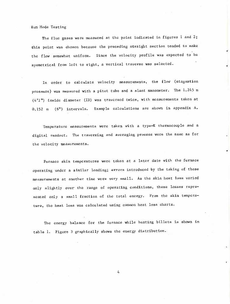
The flue gases were measured at the point indicated in figures 1 and 2;
this point was chosen because the preceding straight section tended to make
the flow somewhat uniform. Since the velocity profile was expected to be
symmetrical from left to right, a vertical traverse was selected.
In order to calculate velocity measurements, the flow (stagnation
pressure) was measured with a pitot tube and a slant manometer. The 1.245 m
(4'1") inside diameter (ID) was traversed twice, with measurements taken at
0.152 m (6") intervals. Example calculations are shown in appendix A.
Temperature measurements were taken with a type-K thermocouple and a
digital readout. The traversing and averaging process were the same as for
the velocity measurements.
Furnace skin temperatures were taken at a later date with the furnace
operating under a similar loading; errors introduced by the taking of these
measurements at another time were very small. As the skin heat loss varied
only slightly over the range of operating conditions, these losses repre-
sented only a small fraction of the total energy. From the skin tempera-
ture, the heat loss was calculated using common heat loss charts.
The energy balance for the furnace while heating billets is shown in
table 1. Figure 3 graphically shows the energy distribution.

i
=> M
®-
t- -tH
(£r
(D—♦
©-
©
i ss: ^ ■
\ ■
V . - - s r ,
*v , i 4 ^^H \ \ \ \ s x u •. <
N \ *;<
-. x \
^ I < ^ -v V V -«. X V \
hi
\ x
' M •
- X
M s
N
- X \ V ^^xs^x^'^>^^
■!-
1
4
e 0)
m >> (0
c
IS (U
•H > a H AH
0) h 3 DO
•H

:9s
I -€)
-©
i 1
&
i s 0- o uJ tr
= -©
^D
0) 4-1 to
CD
50 d
■H 4J 0) •H
C O
0) M 3 60

> a QJ
m J 4J
+J cd
a c 6
i o
g o 0) S-J
o 09 ex a- <
vD O H ^^
vD /—v /■N ^—s ^—N /-*s
!>s O o rH ^1 ro ^—s ^—^ s—^ /<—s OO /—\ •a a)
H <* rH UO r-~ kO CO H o CO r^ H n) !>< O
CT\ ^H O ^H
CM ro <t rH O
CO
H CN rH ^D H o i-H CM o J4 M
A >-.~-- ^^ ~^ *—' "^-^ ^^ ^^ ^^ —* ^^
cd ON 00 r^* vO 00 un o 00 fs o
bo 3 c» og H cn LO en rH CM CM rH
M -P 03 a) m <- o un CN i-H o o O U"| o
d ^
co ^^ ^^ u o o DJ m CO H ON ON iH /--•. rH rH ■H o
d
0)
3 ■M -—* td fn ^ o (U w a u i o i
o IN 00 1—■■
00 rH
o o o IN
o «« 1
o m CN
O LO
rH CM ^^ m
o tn o CM
IN
u
01
IS o
en ON o o
CM I
o rH
CO O rH
o o H r-l r-- rH cd CN [-~ ^
y-i
rH rH r-t
i /-^ i M /-^
1 cd
x: u ^^ ^-~s XI «*N ^—N
t|H u U h o 43 rQ JS 4= m
.a H
Xt X3 ro rH o H rH u-l -* ON o in ^ o O
o A en cn u o o CM o o 0 CM \0 c-g O CM CM
H ^-y \_^ »— 00 1—' N-'
fe a ja x: H
x: x: en M 60 M 50
H £ ^ a ^ ^ 0)
m O-l -* 00 00
ro IN CM •* <t o^ r^ (N en cn m Osl ^
O H
M ■H |Z B < H C
o O
Hi Ix •rl fc! (0 > 5 4-1 o ed •H S cd « cs 4J p •H 3 g
6 id 2 XI o £3 (U ^H ^4 W en a rH W 4-1 td QJ 4J &. PH 1—1 u & ^ QJ ^
u 3 3 QJ tH d u S^ o
■u 0 H 3 H •rl o o H u cd QJ O rH •H ^ o o O u a i2 H fe pq CO n n H w

60 U C Oi M a w
So
1 M VJ 0 o u 1J u ra w VJ 0) D. fN? 9 on u OJ ^H
D5
CM
en
o
tt)
3 4J
CO
%
ti u OJ
Idle Mode Testing
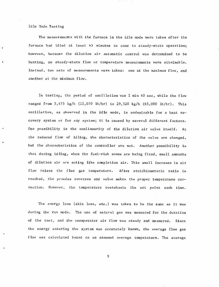
The measurements with the furnace in the idle mode were taken after the
furnace had idled at least 45 minutes to come to steady-state operation;
however, because the dilution air automatic control was determined to be
hunting, no steady-state flow or temperature measurements were attainable.
Instead, two sets of measurements were taken: one at the maximum flow, and
another at the minimum flow.
In testing, the period of oscillation was 2 min 40 sec, while the flow
ranged from 5,475 kg/h (12,070 Ib/hr) to 29,520 kg/h (65,080 Ib/hr). This
oscillation, as observed in the idle mode, is undesirable for a heat re-
covery system or for any system; it is caused by several different factors.
One possibility is the nonlinearity of the dilution air valve itself. At
the reduced flow of idling, the characteristics of the valve are changed,
but the characteristics of the controller are not. Another possibility is
that during idling, when the fuel-rich zones are being fired, small amounts
of dilution air are acting like completion air. This small increase in air
flow raises the flue gas temperature. After stoichioraeteric ratio is
reached, the process reverses and valve makes the proper temperature cor-
rection. However, the temperature overshoots the set point each time.
The energy loss (skin loss, etc.) was taken to be the same as it was
during the run mode. The use of natural gas was measured for the duration
of the test, and the recuperator air flow was steady and measured. Since
the energy entering the system was accurately known, the average flue gas
flow was calculated based on an assumed average temperature. The average

temperature was chosen at 1149°C (2100oF), because the actual energy flux
was closer to the low-flow condition. The mass flow was calculated again,
based on what it would be while maintaining a steady 9270C (1700oF) set
point. The values are shown in table 2.
Energy Losses from Loading Doors
Among the major concerns of the study was the significance of the
energy lost from the loading doors. The results of this investigation can
be summarized as follows.
Energy is lost out of the loading doors in two ways: through radiation
heat from the furnace interior to the surrounding area, and through the
outward flow of hot gas. While the radiation loss was straightforward (any
error would be small), the flow loss was complex, as it interacted with
continuing combustion, entrained outside air, and natural convection.
Therefore, to establish an order of magnitude, crude measurements of velo-
city and temperature were taken. Because all other energy flows were known
to reasonable accuracy, the flow losses from the loading doors were estab-
lished from the energy balance. The crude estimate also served as a check
should other quantities be in error.
The energy lost from the loading is approximately 0.103 x 10 kcal/h
- ft 6 (0.41 x 10 Btu/hr) via radiation, and roughly 0.277 x 10 kcal/h (1.1 x 10
Btu/hr) via outward flow. The total lost energy is roughly 0.378 x 10
kcal/h (1.5 x 10 Btu/hr) or about 8% of the energy available from the fuel.
10

CO c
•H H XI •H
u a re
.H re
x> p^ M M O) c w
CM
<u 1-1
re H
a ^~*. o
0 TJ o O 01 o o ra r^ r^ re CM tH
43 CT\ id
w s TJ -d d 4J > OJ a re c c E 4-J re o
s re ^H
P o o
o O
■H 4-1 re
o C 0 a\ O •H ? o ■H tH <r rH T3 o
03 re rH CM re rH
P O rH ^ M fe
^o o rH ^-v
vO ,~-N ^^ r^ ^—> /-^ ^"s /—^ ^~s /^N
X O ^D DC' «* a> (^ hO oo r^- cn rH CO r% rH <r LO ^0 CO rH c^
i—1 re x CN o n i~- 00 o H o o u rH TH CNJ ^—^ tH s-** ^^ ^^
^—' ^ ^ ^^ (N o es en vO o> in sf en
M 3 H CNJ ro a^ rH 1J0 en o CN
0) FQ <n O ro <D CM OJ O o O
a ^ w
o o ■o-
cu ,—s ,—^ ^—^ 1 ^—s /—N
M ^~s o -3" o o o o 3 o -J- CM o m m oo +J .-N en vD ■* tH r~i o^ r^. re h 00 rH Csl <N ^^ ■H tH
V-l 0 ^ •^s ^~^ ^—f v—^ **-; 0) ^-- <t o. u CO ro a> <^ o ^D tH
go o- cn CM o- rg vO r^. S *.-J- 00 en H 1 o c^ H H tH rH
CM rH
rH
^•^ h ^^ ^^
^s f V- U
u **s 43 42
JS ^H rQ 43 s**
MH x: 1-H rH U o O rC » Xi
H CO o
O O 43
oo o CNl tH
•* O u^ r ^ .w VC ^C CS 00 O
ft M tH tH en O fl -J ■^-^ •w oo H tH ^-^ .c tH
fc,
B
DO
OO
H
43 oc M
it
43
60
M CO \D
4d
M 4<J
00 CO ^ -J Oi O r^ 00 cr> n r. CO
ro rH CM 10 CO 00
u •rj Z <g H
Oi >H en > o
a) re ■H « o O 4-1 w M « 25
d H [-J M 0 re 01 « • M U a hJ 00 5 00
a 0 < <U -H o > C ^4 u 0 H a n iJ <: •H o re QJ O iH 4^ o Z. Pi H fe W n
11

Some heat recovery is possible if the flow from the doors is ducted to
the waste heat boiler. Such a system would have hoods as near as possible
to the doors, insulated ducts to the boiler inlet, and dampers to shut off
the flow when the doors are closed.
Not all of the 0.277 x 10 kcal/h (1.1 x 10⁶ Btu/hr) energy loss can be
recovered. Suppose, for example, that a carefully placed hood collected 75%
of the escaping flow and diluted it with an equal quantity of room air. The
resulting temperature would be approximately:
1093°C | 210C = 557°c(2000OF2+70°F = 1035°F.)
Allowing for some loss in the duct, the flow arriving at the boiler would be
about 5380C (1000°F). The specific heat in this range is 0.26 cal/g0C
(Btu/lb0F) so the heat recovery would be:
0.26 x (1000 - 250) x 2090 x 0.75 x 2
= 0.15 x 10⁶ kcal/h (0.61 x 10⁶ Btu/hr).
This represents an increase of 272 kg/h (600 Ib/hr) of steam production.
During the heating season, the flow escaping from the loading doors
contributes to the heating of the forge shop. The above example shows that
0.277 x 10 kcal/h (1.1 x 10 Btu/hr) worth of heating is replaced by 0.15 x
10 kcal/h (0.61 x 10 Btu/hr). Additionally, withdrawing air from the
building requires that it be replaced with outdoor air. Using a specific
heat of 0.24 and an outdoor temperature of -180C (0oF), this additional loss
is:
0.24 x (70 - 0) x 2090 x 0.75 x 2
= 0.01 x 10⁶ kcal/h (0.05 x 10⁶ Btu/hr).
12
Thus, during part of the heating season, heat recovery from the loading
doors is, in fact, a heat loss.
On a annual basis, a well-designed system recovering heat from the
loading doors can make a small contribution toward energy costs. A system
not carefully designed and controlled can have the opposite effect.
Efficiency of Waste Heat Boilers
Boiler efficiency, an important and meaningful concept in relation to
fired boilers, is defined as follows:
^jrj-. . Steam energy Efficiency = ■=—; &i
Fuel energy
Developing a parallel efficiency for waste heat boilers, the concept
becomes:
■occ- . Steam energy Efficiency = .,°; ^— Energy available
The energy available is the sensible heat plus the latent heat of the
flue gas or
Where;
1. C , (T, - T . ) + xhfr_r,|m = Energy available
C = Average flue gas specific heat from T1 to T
T. ■ Initial (high) flue gas temperature
amb
T , = Ambient temperature, which is the lowest temperature to
which the flue gases can be cooled
13
h = Latent heat of the water vapor in kcal/kg (Btu/lb)^ fg
m = Mass flow of the flue gas
Note that latent heat is almost never from flue gas, but is traditionally
included in the available energy.
The net energy absorbed by the steam will be equal to the energy given
by the flue gas less any heat losses through the casing or:
Steam energy = C „ (Tj- T2 ) - Q casing
Where:
C = Average flue gas specific heat from T^ to T^
T = Temperature of flue gas exiting the heat recovery
system
Q casing = Casing heat loss
Looking at the expression for Energy available, it is obvious that T^
is rather arbitrary and must be specified if efficiency is to be well de-
fined. The other terms are not arbitrary, but must be accurately known if
efficiency is to be specified.
The boiler manufacturer controls two quantities in the expression for
Steam energy, T2 and Q casing. Thus, specifying the above two quantities is
equivalent to specifying boiler efficiency, but with the advantage of not
having to select T,^ or accurately know the latent heat in the flue gas.
14

T9 has been chosen at 1210C (250oF). As will be explained in the
Economic Analysis section, this selection maximizes heat recovery without
requiring excessive heating surface.
Error in Measured Values
The measured heat flows show 0.094 x 10 kcal/h (0.37 x 10 Btu/hr)
less energy entering the control volume than leaving it (a 2% error based on
the entering energy). However, for purposes of specifying a waste heat
boiler, the flows and temperatures as measured are adequate. These measured
values are also adequate for purposes of the economic analysis. Nonethe-
less, this error is worth some discussion and need not be a mystery.
Because the flow out the doors is complicated (with combined natural
convection and forced flow, combustion external to the furnace, and en-
trained outside air), the measurement of outward flow is only a crude ap-
proximation. The real flow out the doors should fall in the range of ^ to 2
times the measured value. This flow should be determinable from the energy
balance. Thus, a strong possibility exists that the entire error is attri-
butable to the doors.
The other possibility relates to the measured flue gas flow. Error
analysis shows that the energy flow should be within 10% of the measured
value. The maximum combined temperature and flow error could be about 0.298
x 106 kcal/h (1.17 x 10⁶ Btu/hr).
15

Each of the measurements is subject to some error. The two quantities
just discussed (the flue gas energy flow and the door energy flow) are the
least accurate as measured, and a detailed analysis of the other quantities
would serve no useful purpose. In subsequent work, the most conservative
values will be used in each case.
DEVELOPMENT OF SYSTEM CONCEPTS
Based on the field survey results, several concepts were considered for
a waste heat recovery system. A discussion of each follows:
Concept 1
The boiler is on the roof of the Forge Shop; the existing stack
(recuperator) is replaced with a tube-type recuperator (figure 4).
Advantages are:
1. Ducting is minimized, yielding a clean compact system.
2. Higher preheat temperatures can be attained with a tube-type
recuperator.
Disadvantages are:
1. The present system has a delicate control scheme although an ID fan
with a control damper could duplicate the present system when the
boiler is on-line. However, when no need exists for steam or when
the boiler is down for maintenence, a control system much like the
present one would be required.
16

I i
4J C <u o c 0 u
.1)
u o
17

2. The present preheat temperatures are just within the acceptable
range for carbon steel, which leads to the belief that carbon steel
is used between the recuperator and the furnace. Any significant
increase in recuperative preheating, therefore, would require a
change to a heat-resistant alloy.
3. Recuperators are very expensive because of the super alloys re-
quired.
4. This concept is closer to a system redesign rather than a simple
retrofit. Replacement of the recuperator, not including modificat-
ions to the stack, would cost approximately $50,000.
Concept 2
The boiler is on the roof, ducted from the top of the existing stack,
with one boiler per exhaust stack.
Advantages are:
1. Because the existing recuperator and stack are left unaltered, the
furnace can be operated as it is presently whenever the boiler is
off-line."
Disadvantages are:
1. Two boilers would be required. Each boiler would operate
only half of the time, thus resulting in higher operating costs to
produce steam from the total energy generated during current pro-
duction.
18

2. Additional ducting at a cost of $10,000 would be required.
Concept 3
The boiler is sized to handle the capacity of one furnace, but ducted
to two furnaces.
Advantages are:
1. The exhaust from either of two furnaces can be used to generate
steam without duplication of the boiler, fan, stack, cold-weather
protection, and much of the additional cost associated with this
hardware.
2. The fan is sized for the normal flow rate and does not unneces-
sarily use up electrical power.
Disadvantages are:
1. The boiler cannot generate twice the steam if two furnaces are used
at once (mobilization).
2. If the boiler is down for repair, no waste heat steam can be gene-
rated.
3. Additional ducting is required.
Concept 4
One boiler, ducted to two stacks, is sized to handle the capacity of
both furnaces.
19
Advantages are:
1. The boiler can generate steam from both furnaces at once (mobili-
zation) .
2. Compared to concept 2, much duplication of equipment is eliminated.
3. When just one furnace is in use, the large boiler generates slight-
ly more steam than would a small one.
Disadvantages are:
1. Two fans, or a single oversized fan, are required.
2. Extra ducting is required.
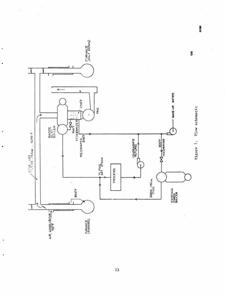
Figure 5 shows a view of system concept 3, while figure 6 illustrates
concept 4. Figure 7 is a flow schematic of the conceptualized system.
Concepts 1 and 2 were rejected because they clearly have poorer eco-
nomic and operational performance characteristics, as compared to concepts 3
and 4. Because of their similarity in economic advantage, concepts 3 and 4
were selected as the best potential candidates for the waste heat recovery
system; hence, an economic analysis was undertaken.
ECONOMICS OF WASTE HEAT-GENERATED STEAM
The economic analysis included an investigation of the potential value
of the steam generated by the waste heat boiler. This value is an important
consideration as any steam generated beyond what is immediately needed is
worthless.
20

■ ID
1
I
!
i !
-<£
©
o. o G 0 u
> o o
01 W
0) U a bo
•H
21

= -■ (5)
0 <
1 g
ui
nj O c o o
i o
u
0) pa
0)
3 CO
■H
22
2
o m
(U u 3 00
UU-ffl
23

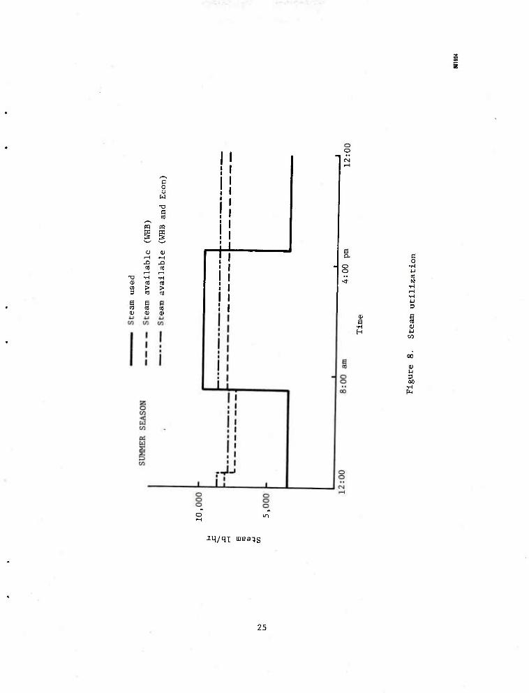
First, consider summer steam use. Based on an average of four repre-
sentative work weeks (1979), the average steam use for a work day is 66,814
kg (147,325 lb). Based on a Saturday average, the steam use on a nonwork
day is 38,291 kg (84,431 lb).
The rate of steam use during the nonworking hours of a week day is
assumed the same as the Saturday rate. The rate of steam use during working
hours is, therefore, 4448 kg/h (9807 Ib/hr). Average steam use during
nonworking hours is 1595 kg/h (3518 Ib/hr).
v
Steam generated by a waste heat boiler operating at an exhaust tempera-
ture of 1790C (3550F) is as follows:
3670 kg/h (8092 Ib/hr) while running
3337 kg/h (7357 Ib/hr) while running
268 kg/h (590 Ib/hr) additionally, if an economizer is added to bring
the exhaust to 1210C (250oF).
These figures are based on the measured flows and temperatures, allowing for
the recuperator, and for the duct losses.
The hourly steam schedule is shown in figure 8. The steam-use-day is
assumed at 10 hours and the run mode of steam production is assumed at 17
hours. That is, the forging furnace runs billets for two shifts, producing
stored heat for nearly an hour.
From the 1979 steam-use records, the heating season tapers off in April
and begins again in October. Using a six-month heating season as an
24
i i
B o u w
B
PQ PQ
I! o o
Hi 01
^3 ^3 id « H rH
XI •H ■H OJ (fl td en > > 3 n) a)
e e § to cd 9 0) 0) a)
+ i! ! I I I I I
E
O o
OJ
a
0 O
•H ■U m N
•H rH •H 4-1 3
a OJ
oo
0)
3 60
•H
aq/qi uiBsqs
25
average, the. hourly use rarely falls below waste heat boiler maximum pro-
duction. It is assumed that all the steam generated during the heating
season can be used.
The use of waste heat boiler steam is as follows:
6 6 Summer without economizer = 8.04 x 10 kg (17.73 x 10 lb)
6 6 Summer with economizer = 8.36 x 10 kg (18.44 x 10 lb)
6 6 ' Winter without economizer = 12.21 x 10 kg (26.92 x 10 lb)
Winter with economizer = 12.98 x 10 kg (28.62 x 10 lb)
Annually without economizer = 20.25 x 10 kg (44.65 x 10 lb)
6 6 Annually with economizer = 21.34 x 10 kg (47.06 x 10 lb)
The above calculations are based on concept 3, and assume no mobilization
production rates.
ECONOMIC ANALYSIS - CONCEPT 3
Cost of Steam
Criteria to establish the cost of steam were based on the following
factors:
• HHV 9217 kcal/ra3 0.025 Btu/ft j (per gas company)
• Boiler efficiency of 82% (per ARRADCOM)
• $0.092/m3 ($2.60/1000 ft3) (per ARRADCOM)
• 575.3 kcal/kg (1023.2 Btu/lb) steam (based on 5%
blowdown and 930C (200oF) feedwater)
26

The application of these factors resulted in the following cost equa-
tion:
1023,2 Btu 1 $2.60 ft3 Cost = x x s- x
(lb) steam 0.82 1000 ft 1025 Btu
= $6.97 / $3.16 \ 1000 kg steam V 1000 lb steam ^
Annual Savings in Gas Costs
Using the above cost equation, the annual savings in gas costs* are:
$141,300 without economizer
$148,700 with economizer
Annual Costs
Electricity, maintenance and operating expenses were established as
follows:
Electric Power:
Fan Power Miscellaneous
$ 966 $ 34
Maintenance (average for first 10 years):
5 man-days/yr at $25/hr Materials
Operating (estimated additional boiler watch time:
240 hr/yr at $25/hr
$1000 $ 500
$6000 $8500
*Figures are rounded off to the nearest $100.
27

Net Annual Savings
By subtracting the annual operating costs ($8500) from the annual
savings in gas costs, the net annual savings for concept 3 are:
$ 132,800 without economizer
$ 140,200 with economizer
First Costs
Calculations to establish the first costs for concept 3 were generated
through manufacturers' estimates, vendor quotes and engineering estimates.
(Refer to appendix B for an Itemized list of suppliers and component
weights.) First costs are as follows:
28

Description
Boiler, trim, F.W. regulator, nonreturn valve
Ducts, fabrication, insulation
Stack dampers, controls
Inlet plenum
Stack
Fan, motor, damper, controls
Expansion joints
Remote indicators
Structural steel
System erection
Project engineering
Steam piping
Shipping
Cold weather protection
Miscellaneous (startup assistance, debugging, ladders, and contingency)
Without With Economizer ($) Economizer($)
51,000 63,000
17,400 17,400
10,700 10,700
5,200 5,200
1,000 1,000
3,170 2,955
3,000 3,000
1,500 1,500
8,000 8,000
14,300 14,300
41,900 41,900
3,760 3,760
2,340 2,340
7,500 7,500
15,000 15,500 $185,770 $198,055
29
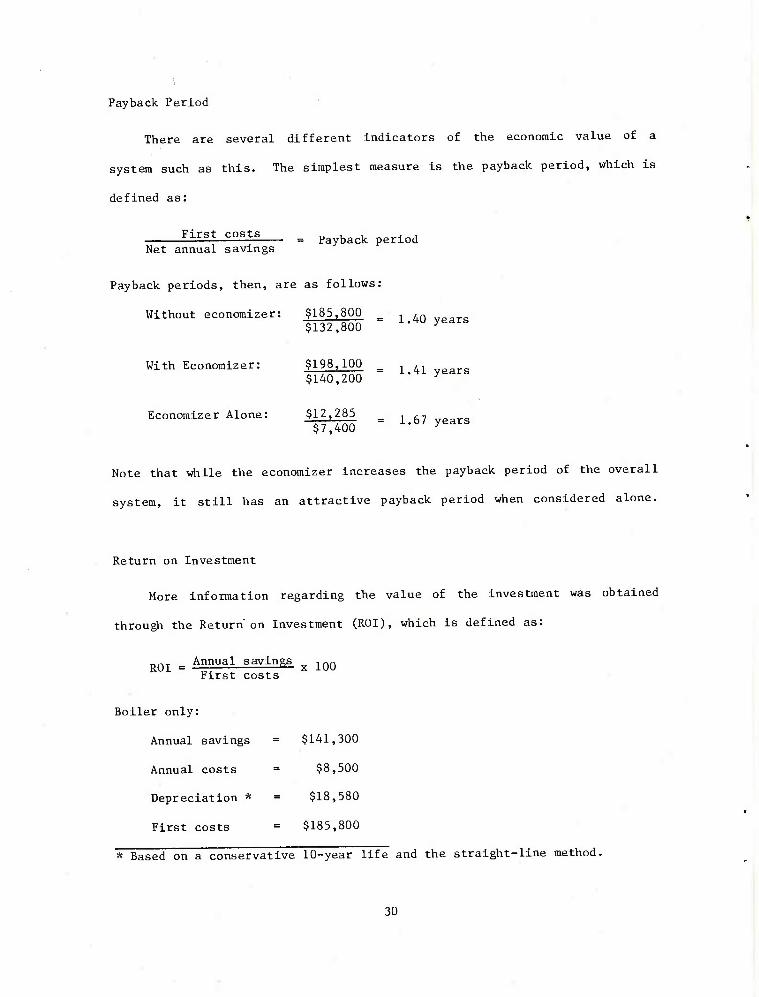
Payback Period
There are several different indicators of the economic value of a
system such as this. The simplest measure is the payback period, which is
defined as:
First costs Net annual savings
Payback periods, then, are as follows
Payback period
Without economizer: $185,800 , ,n ,7„aT.a $132,800 ~ i^U yearS
With Economizer: $198,100 _ $140,200
Economizer Alone: $12,285 $7,400
1.41 years
1.67 years
Note that while the economizer increases the payback period of the overall
system, it still has an attractive payback period when considered alone.
Return on Investment
More information regarding the value of the investment was obtained
through the Return" on Investment (ROI), which is defined as:
ROI = Annual savlnSs x 100 First costs
Boiler only:
Annual savings = $141,300
Annual costs = $8,500
Depreciation * = $18,580
First costs = $185,800
* Based on a conservative 10-year life and the straight-line method.
30
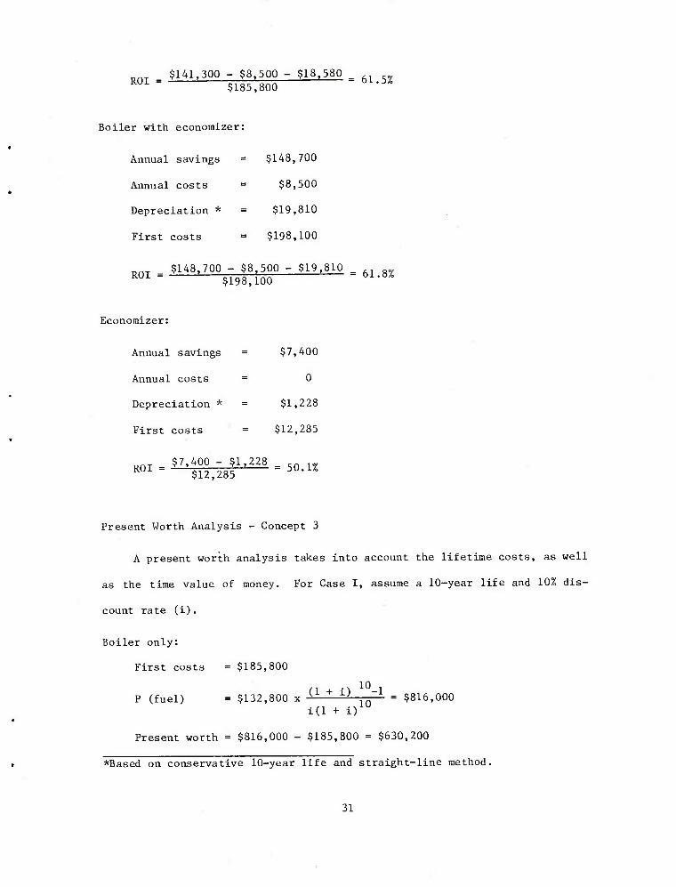
TjnT $141,300 - $8,500 - $18,580 _ R01 = $185,800 bi-V°
Boiler with economizer:
Annual savings = $148,700
Annual costs = $8,500
Depreciation * = $19,810
First costs = $198,100
_ $148,700 - $8,500 - $19,810 = R01 " $198,100 * /o
Economizer:
Annual savings = $7,400
Annual costs = 0
Depreciation * = $1,228
First costs = $12,285
^■iZ^zM.so.u
Present Worth Analysis - Concept 3
A present worth analysis takes into account the lifetime costs, as well
as the time value of money. For Case I, assume a 10-year life and 10% dis-
count rate (i).
Boiler only:
First costs = $185,800
n 10-i P (fuel) = $132,800 x ^ + i; 10 = $816,000
1(1 + i)
Present worth = $816,000 - $185,800 = $630,200
*Based on conservative 10-year life and straight-line method.
31
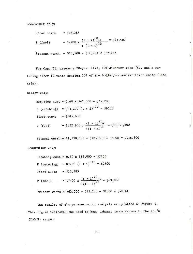
Economizer only:
First costs = $12,285
„,<A„ (1 + i)10-l = $45,500 P (fuel) = $7400 x ■> L jo
i (1 + i)
Present worth - $45,500 - $12,285 = $32,215
For Case II, assume a 20-year life, 10% discount rate (i), and a re-
tubing after 12 years costing 60% of the boiler/economizer first costs (less
trim).
Boiler only:
Retubing cost = 0.60 x $42,060 = $25,200
P (retubing) = $25,200 (1 + i)"12 = $8000
First costs = $185,800
.,20 . P (fuel) = $132,800 x U + ^ " = $1,130,600
id + i) U
Present worth = $1,130,600 - $185,800 - $8000 = $936,800
Economizer only:
Retubing cost-= 0.60 x $12,000 = $7200
P (retubing) = $7200 (1 + i)~12 = $2300
First costs = $12,285
n20 P (fuel) = $7400 x U + l; 2o
1 = $63,000 1(1 + i)
Present worth = $63,000 - $12,285 - $2300 = $48,415
The results of the present worth analysis are plotted on figure 9.
This figure indicates the need to keep exhaust temperatures in the 121"C
(250oF) range.
32

000 000 1$ x R^ow ^uasaaj
o CO
U
4J n! <U tx B 01 H
3
CO
ra
o r-l
u 3 4J cd
0) ft B 0) u
to 3 cB
^3
0)
3
>
o
c a 01
a) 3 M
33

ECONOMIC ANALYSIS - CONCEPT 4
Annual Savings in Gas Costs
Criteria to establish the cost of steam were the same as for concept 3,
excepting the exhaust temperature, which was based on 1160C (240oF); this
represents a 1% increase in steam production over concept 3 due to flowing
the exhaust of one furnace into a boiler sized for two furnaces.
Using the cost equation then, the annual savings in gas costs for
concept 4 (including an economizer) are $149,800. Based on the same annual
costs ($8500), the net annual savings are $141,300.
34

First Costs
Concept 4, as described, is sized for mobilization and Includes an
economizer. First costs are as follows:
Description System with Economizer($)
Boiler, trim, F.W. regulator, nonreturn valve
Ducting, insulation, fabrication
Dampers, controls
Inlet plenum
Stack
Fan, motor, controls
Expansion joints
Remote indicators
Structural steel
System erection
Project engineering
Steam and feedwater piping
Shipping
Cold weather protection
Miscellaneous - Start-up assistance, debugging, ladders, contingency
70,000*
17,400
10,700
7,000*
1,400*
5,200*
3,000
1,500
12,000*
17,000*
41,900
5,200*
2,500*
8,000*
15,500 $218,300
* Changed from concept 3 due to bigger boiler, fan.
35
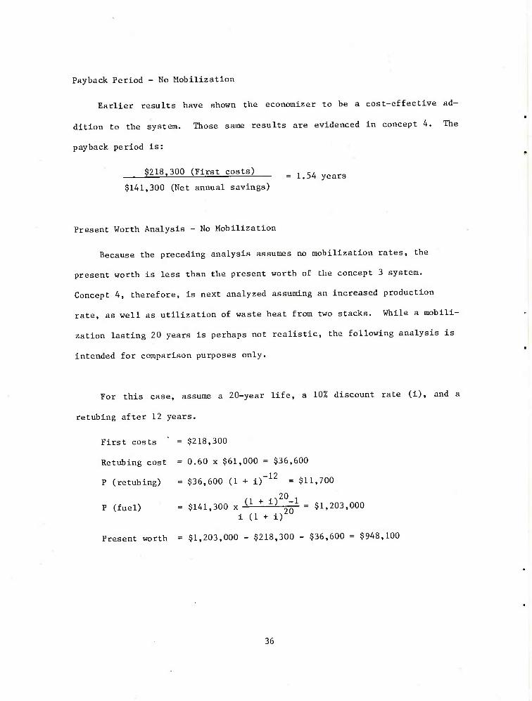
Payback Period - No Mobilization
Earlier results have shown the economizer to be a cost-effective ad-
dition to the system. Those same results are evidenced in concept 4. The
payback period is:
$218,300 (First costs) = 1>54 yearg
$141,300 (Net annual savings)
Present Worth Analysis - No Mobilization
Because the preceding analysis assumes no mobilization rates, the
present worth is less than the present worth of the concept 3 system.
Concept 4, therefore, is next analyzed assuming an increased production
rate, as well as utilization of waste heat from two stacks. While a mobili-
zation lasting 20 years is perhaps not realistic, the following analysis is
intended for comparison purposes only.
For this case, assume a 20-year life, a 10% discount rate (i), and a
retubing after 12 years.
First costs " = $218,300
Retubing cost = 0.60 x $61,000 = $36,600
P (retubing) = $36,600 (1 + i)"12 = $11,700
..20, P (fuel) = $141,300 x U + 1-) 20 - $1,203,000
i (1 + i)
Present worth = $1,203,000 - $218,300 - $36,600 = $948,100
36
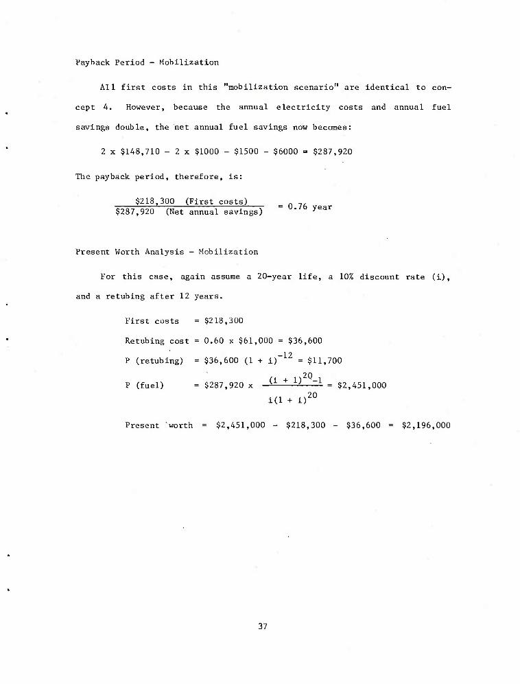
Payback Period - Mobilization
All first costs in this "mobilization scenario" are identical to con-
cept 4. However, because the annual electricity costs and annual fuel
savings double, the net annual fuel savings now becomes:
2 x $148,710 - 2 x $1000 - $1500 - $6000 = $287,920
The payback period, therefore, is:
$218,300 (First costs) $287,920 (Net annual savings)
0.76 year
Present Worth Analysis - Mobilization
For this case, again assume a 20-year life, a 10% discount rate (i),
and a retubing after 12 years.
First costs = $218,300
Retubing cost = 0.60 x $61,000 = $36,600
P (retubing) = $36,600 (1 + i)"12 = $11,700
C n20 1 P (fuel) = $287,920 x -^ ^—— = $2,451,000
id + D20
Present "worth = $2,451,000 - $218,300 - $36,600 = $2,196,000
37
CONCLUSIONS
Waste heat recovery systems that retain the present stack, and control
arrangements are preferred for two reasons:
1. The back pressure control system is delicate but functional.
There is, then, concern among operating personnel that a change
in the system will cause serious control problems.
2. If, for any reason, the waste heat recovery system is down, pro-
duction will continue as usual.
Concepts 3 and 4 satisfy the above requirements; both have ducts run-
ning from the tops of two stacks to a single waste heat boiler and fan.
While either would be an excellent investment, concept 4 is selected because
it is designed with a boiler and fan large enough to recover heat from both
stacks at once; hence, it offers greater flexibility than a one-stack-at-
a-time system (concept 3).
Additionally, concept 4 offers another important advantage in that it
has the capability of generating waste heat steam during mobilization pro-
duction; this is extremely important in relation to the activities at SAAP.
The economic comparisons in table 3 show that the three most likely
systems (concept 3 without economizer, concept 4 without economizer, and
concept 4 with economizer, at current production) have nearly the same
present worth, as well as similar payback periods. Concept 4, including an
38
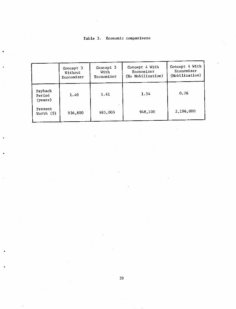
Table 3. Economic comparisons
Payback Period (years)
Present Worth ($)
Concept 3 Without
Economizer
1.40
936,800
Concept 3 With
Economizer
1.41
985,000
Concept 4 With Economizer
(No Mobilization)
1.54
948,100
Concept 4 With Economizer
(Mobilization)
0.76
2,196,000
39
economizer and at mobilization production, offers a very quick payback
period, even through its present worth is much greater than the other three
systems. Further, given even a small possibility of mobilization pro-
duction, concept 4 is again the best choice.
RECOMMENDATIONS
As a means of stabilizing the system and regulating the dilution air
control valve, MTI suggests the addition of a variable inlet vane damper to
the fan. The cost of this system adaptation would be quickly recovered by a
reduction in fan power consumption. If the waste heat recovery system was
added to the present system without correcting this hunting control, it
would generate approximately three times more capacity than is required.
Recovering heat from the loading doors offers little incentive and,
therefore, is not suggested. However, if it is desirable to exhaust the
escaping flow for purposes of clean air, MTI recommends ducting to the waste
heat boiler in order to minimize the heat loss. Such a system must be
carefully designed to ensure the highest level of system performance.
Based on the comparison of concepts, in conjunction with the economic
assessment, a waste heat recovery system representative of concept 4
(including an economizer) offers the greatest degree of flexibility and
economy. Installation of such a system, sized for mobilization, is recom-
mended as soon as possible.
40
System Control
The control concept is illustrated in figure 10 (all instrumentation is
not shown). The controls will try to maintain 85 psig steam from the waste
heat boiler. If the waste heat boiler is meeting the demand, the fired
boiler will sense that its set point of 75 psig is exceeded and, therefore,
will not generate steam. When the waste heat boiler fails to meet the steam
demand, the fired boiler will cut in as steam pressure falls below 75 psig.
Manual control will be used to start up and shut down the system.
Safety Control
Protection of plant personnel and protection of equipment are primary
considerations in the design of a waste heat recovery system. Both of these
considerations are taken into account as follows:
The steam side of the system should be designed according to ASME
Section I recommendations. Boilers designed to this code have demonstrated
remarkably good safety records; hence, there is little to be gained by going
beyond code requirements.
Specifications call for personnel protection on high-temperature sur-
faces; the project engineer must make certain that the supplier complies
with these requirements. Because it is likely that there will be small hot
spots not anticipated by the vendor, the project engineer and plant per-
sonnel will have to handle minor deviations as they appear.
The waste heat recovery system should have as little effect as possible
on the existing equipment, and failure in the system should not endanger the
forge furnace system. Steps to be taken are as follows:
41

i
Q.
o u u g
5o
42

1. In the event of a control air failure, the fan damper fails closed
and the stack damper fails open.
2. If any excesses in stack pressure are detected, either of the
dampers can be controlled manually.
3. The stack damper cannot be closed unless there is power to the fan.
If the fan should lose power, the stack damper opens.
4. The boiler is equipped with high- and low-water level alarms as
well as with a remote level indicator.
43

APPENDIX A. SAMPLE CALCULATIONS
Local Velocity
The temperature - density behavior of the combustion products will be
closely approximated by the ideal gas equation:
P - -gj- (D
P = pressure 14.7 lbf/in.2 or 2116.8 lbf/ft
2
3 p = density (lb /ft )
m
M = molecular wt 29 lb/mole
R = gas constant 1545 ft lbf/0R mole
T = temperature (0R)
Solving for velocity from Bernoulli's equation:
P - P (V2 - V2) = 2 -^ £ (2)
2 1 p
where
V = velocity (ft/sec)
Referring to Figure A-l and letting the subscript 1 indicate conditions
at the inlet to the pitot tube where V. =0, equation 2 becomes:
/(p, - p,)
At a typical test point:
P - P = 0.075 in. W.C. = 0.390 lbf/ft2
44

0)
< 3 H
rH •H U <0 O U U 1) -H
a 0)
n a)
u o
£
01 U
60 •rH
45
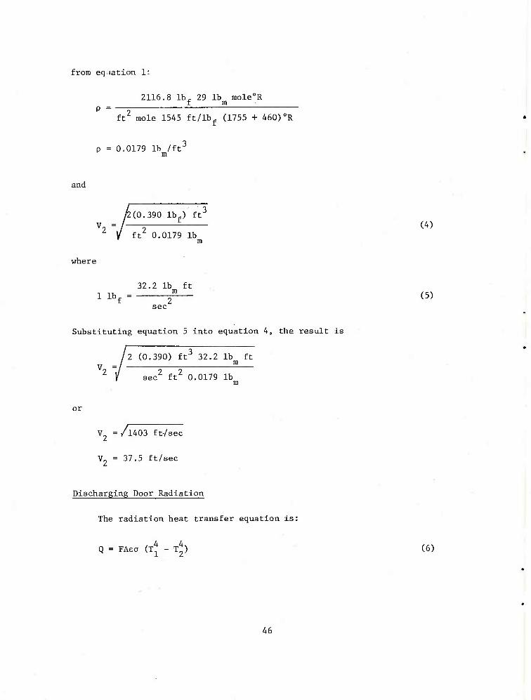
from eq lation 1:
2116.8 lb, 29 lb mole0R __f m
ft2 mole 1545 ft/lbf (1755 + 460)0R
p = 0.0179 lb /ft3 m
and
where
Substituting equation 5 into equation 4, the result is
2 (0.390) ft3 32.2 lb ft V =/ S
sec2 ft2 0.0179 lb m
or
y 2(0.390 lb ) ft3
—2 i (4) ft 0.0179 lb
m
32.2 lb ft 1 lbf = f (5)
sec
V2 = /l403 ft-/£
V = 37.5 ft/sec
Discharging Door Radiation
The radiation heat transfer equation is:
Q = FAea (T^ - T^) (6)
46
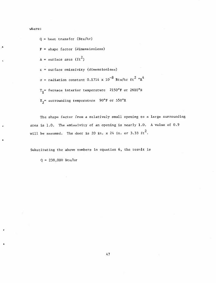
where:
Q = heat transfer (Btu/hr)
F = shape factor (dimensionless)
2 A = surface area (ft )
e = surface emissivity (dimensionless)
—8 2 4 a = radiation constant 0.1714 x 10 Btu/hr ft "R
T = furnace interior temperature 2150oF or 2610°R
T = surrounding temperature 90oF or 550oR
The shape factor from a relatively small opening to a large surrounding
area is 1.0. The emissivity of an opening is nearly 1.0. A value of 0.9
2 will be assumed. The door is 20 in. x 24 in. or 3.33 ft .
Substituting the above numbers in equation 6, the result is
Q = 238,000 Btu/hr
47
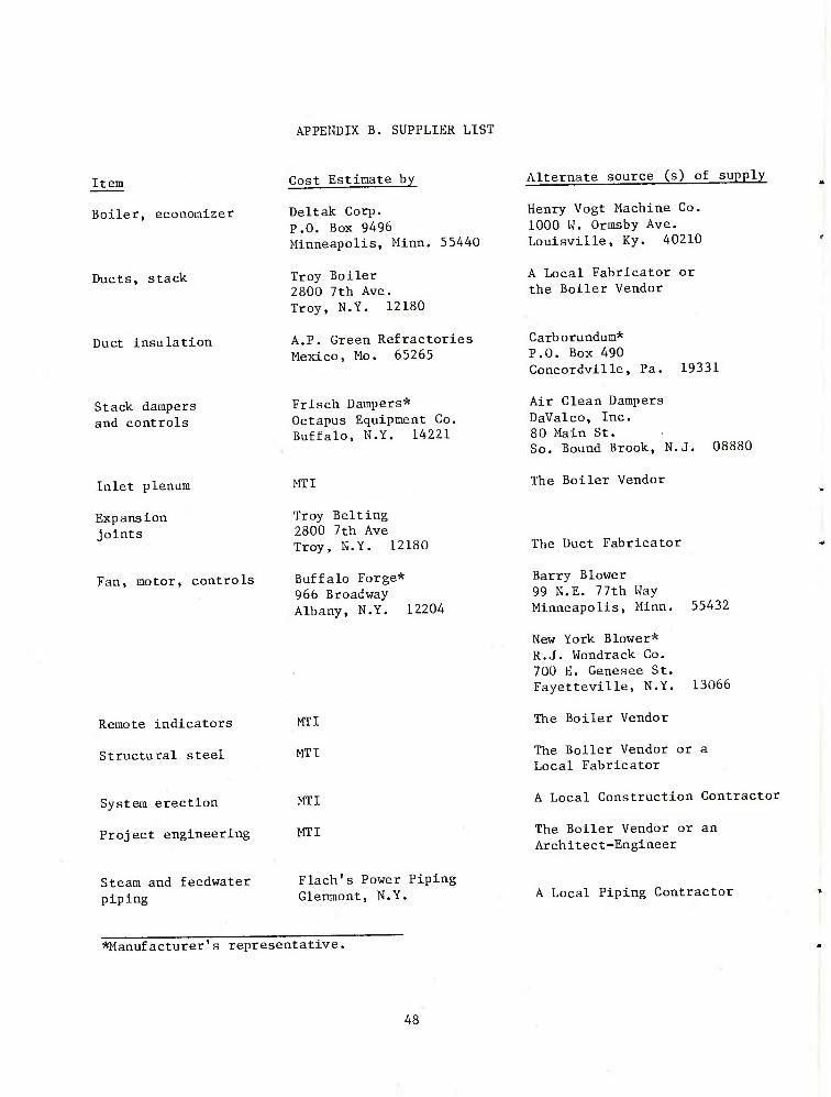
APPENDIX B. SUPPLIER LIST
Item
Boiler, economizer
Ducts, stack
Duct insulation
Stack dampers and controls
Cost Estimate by
Deltak Corp. P.O. Box 9496 Minneapolis, Minn. 55440
Troy Boiler 2800 7th Ave. Troy, N.Y. 12180
A.P. Green Refractories Mexico, Mo. 65265
Frisch Dampers* Octapus Equipment Co. Buffalo, N.Y. 14221
Alternate source (s) of supply
Henry Vogt Machine Co. 1000 W. Ormsby Ave. Louisville, Ky. 40210
A Local Fabricator or the Boiler Vendor
Carborundum* P.O. Box 490 Concordville, Pa. 19331
Air Clean Dampers DaValco, Inc. 80 Main St. So. Bound Brook, N.J. 08880
Inlet plenum
Expansion joints
Fan, motor, controls
Remote indicators
Structural steel
System erection
Project engineering
Steam and feedwater piping
MTI
Troy Belting 2800 7th Ave Troy, N.Y. 12180
Buffalo Forge* 966 Broadway Albany, N.Y. 12204
MTI
MTI
MTI
MTI
Flach's P ower Piping Glenmont, N.Y
The Boiler Vendor
The Duct Fabricator
Barry Blower 99 N.E. 77th Way Minneapolis, Minn. 55432
New York Blower* R.J. Wondrack Co. 700 E. Genesee St. Fayetteville, N.Y. 13066
The Boiler Vendor
The Boiler Vendor or a Local Fabricator
A Local Construction Contractor
The Boiler Vendor or an Architect-Engineer
A Local Piping Contractor
*Manufacturer's representative.
48

Component Weights
Item
Boiler, economizer
Ducts, stack
Dampers
Fan, motor
Structural steel
Estimated Weight kg (lb)
Estimated weight(operating) kg (lb)
12,698 (28,000)
10,567 (23,300) total
860 (1900) each
363 (800)
9100 (20,000)
14,058 (31,000)
10,567 (23,300) total
860 (1900) each
363 (800)
9100 (20,000)
49
DISTRIBUTION LIST
Commander US Army Armament Research & Development Command ATTN: DRDAR-LCU-M (15)
DRDAR-TSS (5) DRDAR-PRW-B
Dover, N.J. 07801
Administrator Defense Technical Information Center ATTN: Accessions Division (12) Cameron Station Alexandria, Va, 22314
Commander DCASMA, Hartford (2) 96 Murphy Road Hartford, Ct. 06114
Weapon System Concept Team/CSL ATTN: DRDAR-ACW Aberdeen Proving Ground, Md. 21010
Technical Library ATTN: DRDAR-CLJ-L Aberdeen Proving Ground, Md. 21010
Director US Army Ballistic Research Laboratory ARRADCOM ATTN: DRDAR-TSB-S Aberdeen Proving Ground, Md. 21005
Bener Weapons Laboratory Technical Library . ATTN: DRDAR-LCD-TL Watervliet, N.Y. 12189
Commander US Army Armament Material Readiness Command ATTN: DRSAR-LEP-L Rock Island, 111. 61299
50

US Army Material Systems Analysis Activity ATTN: DRXSY-MP Aberdeen Proving Ground, Md. 21005
C ommande r US Army Munitions Production Base Modernization Agency ATTN: SARPM-PBM-EC (2) Dover, N.J. 07801
Commander Scranton Army Ammunition Plant (5) Scranton, Pa. 18501
Commander Louisiana Army Ammunition Plant Shreveport, L.A. 71130
51
Related Documents