Journal of Computing and Information Technology - CIT 8, 2000, 4, 341–348 341 Design of Two-Channel Low-Delay FIR Filter Banks Using Constrained Optimization Robert Bregovi´ c and Tapio Saram¨ aki Signal Processing Laboratory, Tampere University of Technology, Tampere, Finland This paper shows the efficiency of using constrained optimization for designing two-channel low-delay finite impulse response filter banks. The filter banks under consideration are quadrature mirror filter QMF banks and perfect reconstruction PR biorthogonal filter banks. The design problems for both types of banks are stated as constrained minimization problems in forms that enable us to minimize the maximum of the stopband energies of the analysis filter s subject to the given passband and transition band constraints of the filter s as well as subject to the given allowable reconstruction error for QMF banks or the PR property for biorthogonal filter banks. For solving the given optimization problems a modified Dutta-Vidyasagar optimization technique has been used. The efficiency of the proposed design methods is illustrated by means of some examples. Keywords: FIR filter banks, low-delay, two-channel, optimization, QMF, biorthogonal 1. Introduction During the last two decades, filter banks have found various applications in many different areas such as speech coding, scrambling, im- age compression, and transmission of signals through channels of different bandwidths 1– 3. The main idea of using filter banks is the ability of the system to separate in the fre- quency domain the signal under consideration into two or more signals or to compose two or more different signals into a single signal. Due to the filtering operations that are performed on the signal passing through the filter bank, a delay between the output and the input sig- nals is introduced. In many applications, it is desirable to keep this delay as short as possi- ble. When using linear-phase finite impulse re- sponse FIR filters in synthesizing filter banks, good filter properties result in many cases in high filter orders and in an intolerably high de- lay. In these applications, low-delay FIR filter banks have to be used. These filter banks are characterized by the property that the orders of the nonlinear-phase building-block FIR filters can be increased to improve the filter properties without increasing the overall delay. For constructing low-delay FIR filter banks, quadrature mirror filter QMF banks and per- fect reconstruction PR filter banks have been used. For the low-delay QMF banks 4 – 6 , the analysis filters are quadrature mirror filters and the PR property cannot be achieved, whereas for PR biorthogonal filter banks 6 – 9 , these filters are related through the PR property and have different characteristics. For designing low-delay QMF banks two itera- tive approaches have been presented by Xu, Lu, and Antoniou in 4 and 5 . The main drawback in these iterative algorithms is that the transition band ripple of the amplitude response is not au- tomatically controlled and it is not straightfor- ward to find proper values for the parameters used in the procedures to give a satisfactory filter performance in the transition band. The larger the difference between the filter order and the desired filter bank delay, the more difficult the problem is. Low-delay PR biorthogonal filter banks have been first introduced by Nayebi, Smith, and Barnwell in 7 and 8 . The filter banks result- ing when using their optimization technique are

Welcome message from author
This document is posted to help you gain knowledge. Please leave a comment to let me know what you think about it! Share it to your friends and learn new things together.
Transcript
Journal of Computing and Information Technology - CIT 8, 2000, 4, 341–348 341
Design of Two-Channel Low-Delay FIRFilter Banks Using ConstrainedOptimization
Robert Bregovic and Tapio SaramakiSignal Processing Laboratory, Tampere University of Technology, Tampere, Finland
This paper shows the efficiency of using constrainedoptimization for designing two-channel low-delay finiteimpulse response filter banks. The filter banks underconsideration are quadrature mirror filter �QMF� banksand perfect reconstruction �PR� biorthogonal filter banks.The design problems for both types of banks are stated asconstrained minimization problems in forms that enableus to minimize the maximum of the stopband energiesof the analysis filter�s� subject to the given passbandand transition band constraints of the filter�s� as well assubject to the given allowable reconstruction error forQMF banks or the PR property for biorthogonal filterbanks. For solving the given optimization problems amodified Dutta-Vidyasagar optimization technique hasbeen used. The efficiency of the proposed designmethods is illustrated by means of some examples.
Keywords: FIR filter banks, low-delay, two-channel,optimization, QMF, biorthogonal
1. Introduction
During the last two decades, filter banks havefound various applications in many differentareas such as speech coding, scrambling, im-age compression, and transmission of signalsthrough channels of different bandwidths �1�–�3�. The main idea of using filter banks isthe ability of the system to separate in the fre-quency domain the signal under considerationinto two or more signals or to compose two ormore different signals into a single signal. Dueto the filtering operations that are performedon the signal passing through the filter bank,a delay between the output and the input sig-nals is introduced. In many applications, it isdesirable to keep this delay as short as possi-ble. When using linear-phase finite impulse re-
sponse �FIR� filters in synthesizing filter banks,good filter properties result in many cases inhigh filter orders and in an intolerably high de-lay. In these applications, low-delay FIR filterbanks have to be used. These filter banks arecharacterized by the property that the orders ofthe nonlinear-phase building-block FIR filterscan be increased to improve the filter propertieswithout increasing the overall delay.
For constructing low-delay FIR filter banks,quadrature mirror filter �QMF� banks and per-fect reconstruction �PR� filter banks have beenused. For the low-delay QMF banks �4�–�6�, theanalysis filters are quadrature mirror filters andthe PR property cannot be achieved, whereasfor PR biorthogonal filter banks �6�–�9�, thesefilters are related through the PR property andhave different characteristics.
For designing low-delay QMF banks two itera-tive approaches have been presented by Xu, Lu,and Antoniou in �4� and �5�. The main drawbackin these iterative algorithms is that the transitionband ripple of the amplitude response is not au-tomatically controlled and it is not straightfor-ward to find proper values for the parametersused in the procedures to give a satisfactoryfilter performance in the transition band. Thelarger the difference between the filter order andthe desired filter bank delay, the more difficultthe problem is.
Low-delay PR biorthogonal filter banks havebeen first introduced by Nayebi, Smith, andBarnwell in �7� and �8�. The filter banks result-ing when using their optimization technique are
342 Design of Two-Channel Low-Delay FIR Filter Banks Using Constrained Optimization
Fig. 1. Two-channel filter bank.
suboptimal, as has been shown in some later pa-pers. However, they have made several impor-tant observations concerning the properties oflow-delay filter banks that apply to PR biorthog-onal filter banks as well as to QMF banks. First,it is not advisable to design filter banks with avery small delay compared to the filter orders,because after a certain filter order for the sameoverall delay, larger orders result only in a neg-ligible improvement in the performance of thefilter bank. Second, additional constraints areusually necessary in the transition bands of thefilters due to the possible artifacts occurring inthese bands. Abdel-Rahem, El-Guibaly, andAntoniou presented in �9� two approaches fordesigning low-delay biorthogonal filter banksbased on the Lagrange-multiplier method. Fil-ter banks designed by their method have bet-ter properties than those designed by Nayebi,Smith, and Barnwell. The method has, like forQMF banks, again problems with the passbandand transition band ripples.
This paper shows how the above-mentionedproblems can be solved in designing two-channellow-delay FIR filter banks by using constrainedoptimization. For both QMF banks and PRbiorthogonal filter banks, the overall synthesisproblem is stated in the form to which the al-gorithm of Dutta and Vidyasagar �10� can beapplied. Several examples are included that il-lustrate the efficiency of the proposed synthe-sis scheme in improving the filter bank perfor-mance. More details on how to apply the Dutta-Vidyasagar algorithm to designing filter bankscan be found in �11� and �12�. A comprehen-sive review on two-channel FIR filter banks hasbeen given in �6�.
2. Two-channel filter banks
This section reviews some basic relations fortwo-channel filter banks. The block diagram fora two-channel filter bank is shown in Fig. 1 �2�.
It consists of an analysis filter bank followedby downsamplers, upsamplers, and a synthesisbank.
It is well known that the relation between theoutput and input of this system is expressible as
Y�z� � T�z�X�z� � A�z�X��z�� �1�
where the terms
T�z� �12�H0�z�F0�z� � H1�z�F1�z�� �2a�
and
A�z� �12�H0��z�F0�z� �H1��z�F1�z�� �2b�
are the distortion transfer function and the alias-ing transfer function, respectively. The secondterm can be made zero by selecting the syn-thesis filters as F0�z� � 2H1��z� and F1�z� ��2H0��z�. In this case, the residual filter bankdistortion becomes
T�z� � H0�z�H1��z�� H1�z�H0��z�� �3�
To simplify the overall design problems to bedescribed in the following sections, we use, in-stead of H0�z� and H1�z�, the following transferfunctions �6�:
G0�z� �N0X
n�0
g0�n�z�n
� H0�z� �N0X
n�0
h0�n�z�n
�4a�
G1�z� �N1X
n�0
g1�n�z�n
� H1��z� �N1X
n�0
��1�nh1�n�z�n
�
�4b�
In the above, G0�z� and H0�z� are identical,whereas G1�z� � H1��z�. Therefore,
Design of Two-Channel Low-Delay FIR Filter Banks Using Constrained Optimization 343
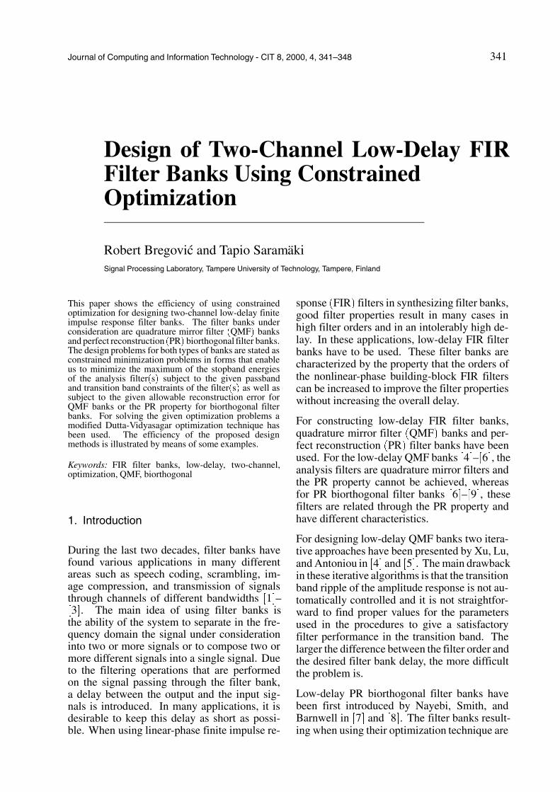
Fig. 2. Specifications for G0�z� and G1�z� as well as the relations between H0�z� and G0�z� and H1�z� and G1�z�.
jG1�ejω �j � jH1�ej�π�ω�� so that the amplituderesponse of G1�z� is obtained from that of H1�z�by means of the substitution π � ω � ω andvice versa. Fig. 2 exemplifies the above rela-tions in addition to showing the constraints forG0�z� and G1�z� that are used in the problemsto be stated in the following sections.
The main advantage of using the above trans-fer functions G0�z� and G1�z�, instead of H0�z�and H1�z�, lies in the fact that they are bothlowpass filters. This makes their optimizationmore straightforward as they can be treated inthe same way and the synthesis formulas can beexpressed in a simplified manner.
3. Low-delay QMF banks
In this section, the definition of low-delay QMFbanks is given, an appropriate design problemis stated, and an optimization procedure is sug-gested for solving this problem.
3.1. Definition of low-delay QMF banks
The low-delay QMF banks proposed by Xu, Lu,and Antoniou �4� are characterized by the fol-lowing properties:
1. G1�z� � G0�z� �PN0
n�0 g0�n�z�n, where N0is an odd integer.
2. jG0�ejω j approximates zero on �ωs� π � �stop-band� and unity on �0� ωp� �passband�.
3. T�z� � �G0�z��2 � �G0��z��2 approximatesthe delay z�K with K is being an odd integersatisfying K � N0.
Because of Property 3, the impulse responseof G0�z� cannot be symmetric so that all theimpulse-response values g0�n� for n � 0, 1,� � � , N0 are unknowns. The reconstruction errorgiven by
jT�ejω �� e�jKω j
� j�G0�ejω ��2 � �G0�e
j�ω�π���2 � e�jKω j�5�
344 Design of Two-Channel Low-Delay FIR Filter Banks Using Constrained Optimization
is desired to be made small in the overall base-band �0� π �. Due to the nonlinear-phase charac-teristics, the performance of G0�z� in the pass-band and in the transition band must also becontrolled.
3.2. Design method for low-delay QMFbanks
For given N0, ρs, ρp, δp, and δa as well asK, the problem is to find the N0 � 1 unknownimpulse-response coefficients g0�n� of G0�z� �PN0
n�0 g0�n�z�n to minimize
ε0 �
Z π
ωs
jG0�ejω �j2dω �6a�
subject to
maxω��0�ωp�
jjG0�ejω �j � 1j � δp�
maxω��ωp�ωs�
jG0�ejω �j � 1 � δp�
�6b�
and
maxω��0�π �
jT�ejω � e�jKω j � maxω��0�π �
j�G0�ejω �2
� �G0�ej�ω�π���2 � e�jKω j � δa� �6c�
where
ωp � �1�ρp�π2
and ωs � �1�ρs�π2�
Here the goal is to minimize the stopband en-ergy of the filter under consideration. The firstcondition of Eq. �6b� forces the maximum pass-band deviation of the amplitude response fromthe unity to be less than or equal to δp, the sec-ond condition of Eq. �6b� forces the transitionband maximum to be less than or equal to 1�δp,and the third condition of Eq. �6c� guaranteesthat the reconstruction error is smaller than orequal to δa. The above optimization problemcan be solved by properly applying the algo-rithm of Dutta and Vidyasagar �10� �see, e. g.,�11� or �12� for details�.
0 5 10 15 20−0.5
0
0.5
Impulse response for E(z): K=7, N0+N
1=22
0 5 10 15 20−0.5
0
0.5Impulse response for −E(−z)
0 5 10 15 200
0.5
1Impulse response for T(z)=E(z)−E(−z)
n in samples
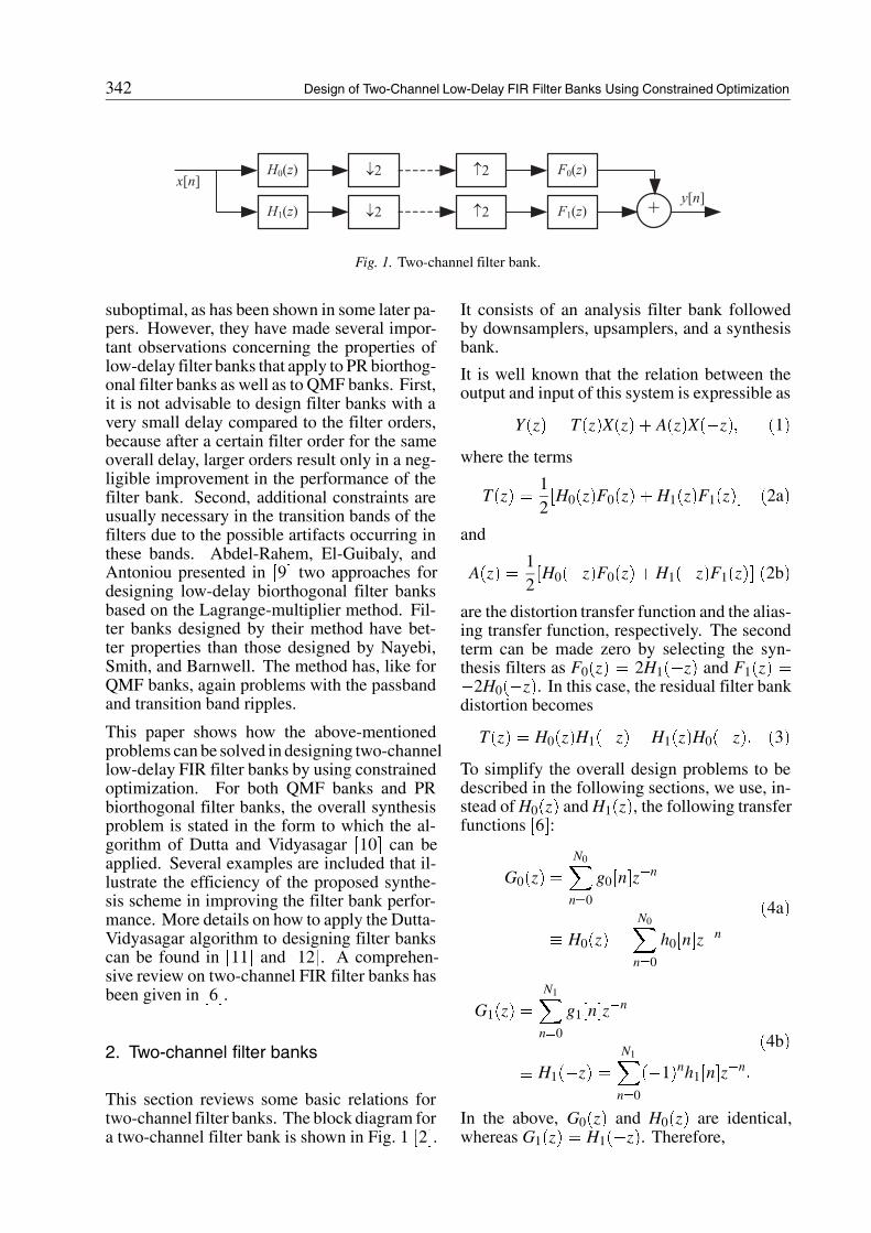
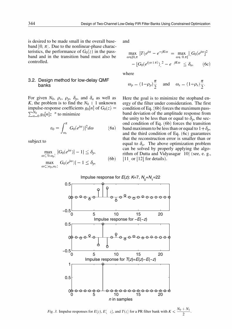
Fig. 3. Impulse responses for E�z�, E��z�, and T�z� for a PR filter bank with K �N0 � N1
2.
Design of Two-Channel Low-Delay FIR Filter Banks Using Constrained Optimization 345
4. Low-delay PR biorthogonal filter banks
In this section, the definition of low-delay PRbiorthogonal banks is given, an appropriate de-sign problem is stated, and an optimization pro-cedure is suggested for solving this problem.
4.1. Definition of low-delay PR biorthogo-nal filter banks
For low-delayPRbiorthogonal filter banksG0�z�and G1�z�, as given by Eqs. �4a� and �4b�, sat-isfy the following conditions:
1. The impulse responses of G0�z� and G1�z�are not symmetric.
2. The impulse response of E�z� � G0�z�G1�z��PN0�N1
n�0 e�n�z�n satisfies
e�n� �
� 12
for n � K
0 for n odd and n �� K��7�
whereK is an odd integerwithK �N0 � N1
2.
An example for an impulse response of E�z� isshown in Fig. 3. The second condition impliesthat the overall transfer function between theoutput and input is T�z� � E�z��E��z� � z�K
with K less thanN0 � N1
2�compare Eqs. �3�
and �4� and see Fig. 3�. The high number ofunknowns �altogether N0 �N1 � 2� and the PRcondition with the delay less than half the sumof the filter orders makes the synthesis of theoverall system very nonlinear and complicated.
4.2. Design method for low-delay PRbiorthogonal filter bank
For given N0, N1, ρ�k�p and ρ�k�s for k � 0, 1,
and δp as well as K, the problem is to find theadjustable coefficients of G0�z� and G1�z�, asgiven by Eqs. �4a� and �4b�, to minimize
ε � max�ε0� ε1� �8a�
where
εk �
Z π
ω �k�s
jGk�ejω �j2dω for k � 0� 1�
�8b�
subject to
maxω��0�ω �k�
p �
jjGk�ejω �j � 1j � δp� for k � 0� 1�
maxω��ω �k�
p �ω �k�s �
jGk�ejω �j � 1 � δp for k � 0� 1�
�8c�and
maxω��0�π �
jG0�ejω �G1�e
jω �
� G0�ej�ω�π��G1�e
j�ω�π��
� e�jKω j � 0�
�8d�
Here, ω �k�p �
�1�ρ�k�p �π2
and ω �k�s �
�1�ρ�k�s �π2
for k � 0, 1 are the passband and stopbandedges for G0�z� and G1�z� as shown in Fig. 2.
This problem is more complicated than the onestated in Section 3.2. Here the goal is to mini-mize the maximum of the stopband energies ofthe two filters under consideration. The condi-tion of Eq. �8d� guarantees that a PR filter bankwill be obtained. The above optimization prob-lem can also be solved by properly applying thealgorithm of Dutta and Vidyasagar �10� �see, e.g., �11� or �12� for details�.
5. Numerical examples
This section illustrates, by means of examples,some characteristics of two-channel low-delayQMF banks and low-delay PR biorthogonal fil-ter banks. In addition, the filter banks result-ing when applying the proposed optimizationscheme are compared to those obtained usingother existing techniques.
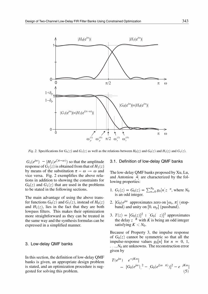
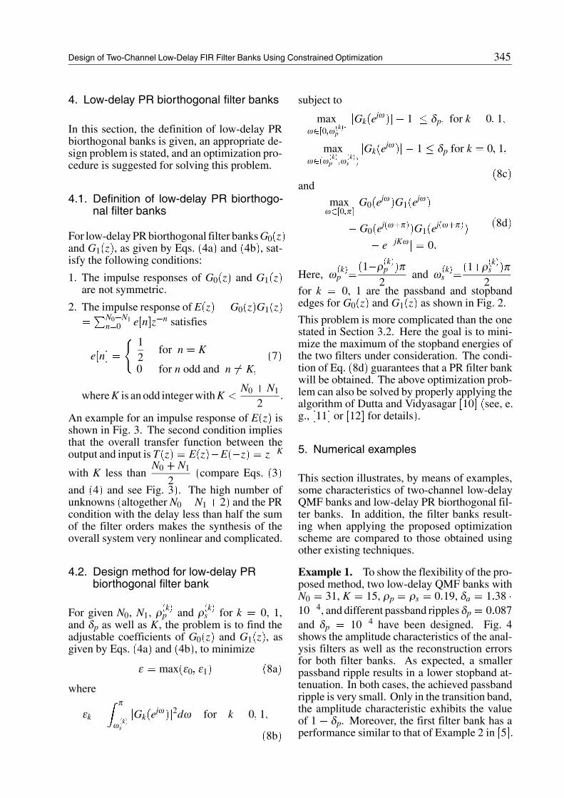
Example 1. To show the flexibility of the pro-posed method, two low-delay QMF banks withN0 � 31, K � 15, ρp � ρs � 0�19, δa � 1�38 �10�4, and different passband ripples δp � 0�087and δp � 10�4 have been designed. Fig. 4shows the amplitude characteristics of the anal-ysis filters as well as the reconstruction errorsfor both filter banks. As expected, a smallerpassband ripple results in a lower stopband at-tenuation. In both cases, the achieved passbandripple is very small. Only in the transition band,the amplitude characteristic exhibits the valueof 1 � δp. Moreover, the first filter bank has aperformance similar to that of Example 2 in �5�.
346 Design of Two-Channel Low-Delay FIR Filter Banks Using Constrained Optimization
0 0.1 0.2 0.3 0.4 0.5−80
−60
−40
−20
0
Normalized frequency (ω/(2π))
Am
plitu
de in
dB
0 0.1 0.2 0.3 0.4 0.5−2
0
2x 10
−4
Rec
onst
ruct
ion
erro
r
Fig. 4. Low-delay QMF banks with N0 � 31 and K � 15. The solid and dot-dashed lines show the amplituderesponses of analysis filters for δp � 0�087 and δp � 10�4, respectively.
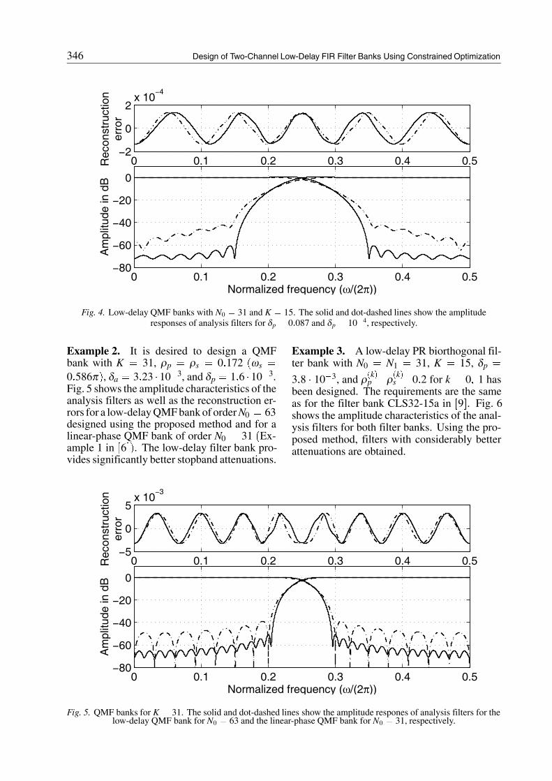
Example 2. It is desired to design a QMFbank with K � 31, ρp � ρs � 0�172 �ωs �0�586π�, δa � 3�23 �10�3, and δp � 1�6 � 10�3.Fig. 5 shows the amplitude characteristics of theanalysis filters as well as the reconstruction er-rors for a low-delayQMFbankof orderN0 � 63designed using the proposed method and for alinear-phase QMF bank of order N0 � 31 �Ex-ample 1 in �6��. The low-delay filter bank pro-vides significantly better stopband attenuations.
Example 3. A low-delay PR biorthogonal fil-ter bank with N0 � N1 � 31, K � 15, δp �
3�8 � 10�3, and ρ�k�p �ρ�k�s �0�2 for k � 0� 1 hasbeen designed. The requirements are the sameas for the filter bank CLS32-15a in �9�. Fig. 6shows the amplitude characteristics of the anal-ysis filters for both filter banks. Using the pro-posed method, filters with considerably betterattenuations are obtained.
0 0.1 0.2 0.3 0.4 0.5−80
−60
−40
−20
0
Normalized frequency (ω/(2π))
Am
plitu
de in
dB
0 0.1 0.2 0.3 0.4 0.5−5
0
5x 10
−3
Rec
onst
ruct
ion
erro
r
Fig. 5. QMF banks for K � 31. The solid and dot-dashed lines show the amplitude respones of analysis filters for thelow-delay QMF bank for N0 � 63 and the linear-phase QMF bank for N0 � 31, respectively.
Design of Two-Channel Low-Delay FIR Filter Banks Using Constrained Optimization 347
0 0.1 0.2 0.3 0.4 0.5−60
−40
−20
0
Normalized frequency (ω/(2π))
Am
plitu
de in
dB
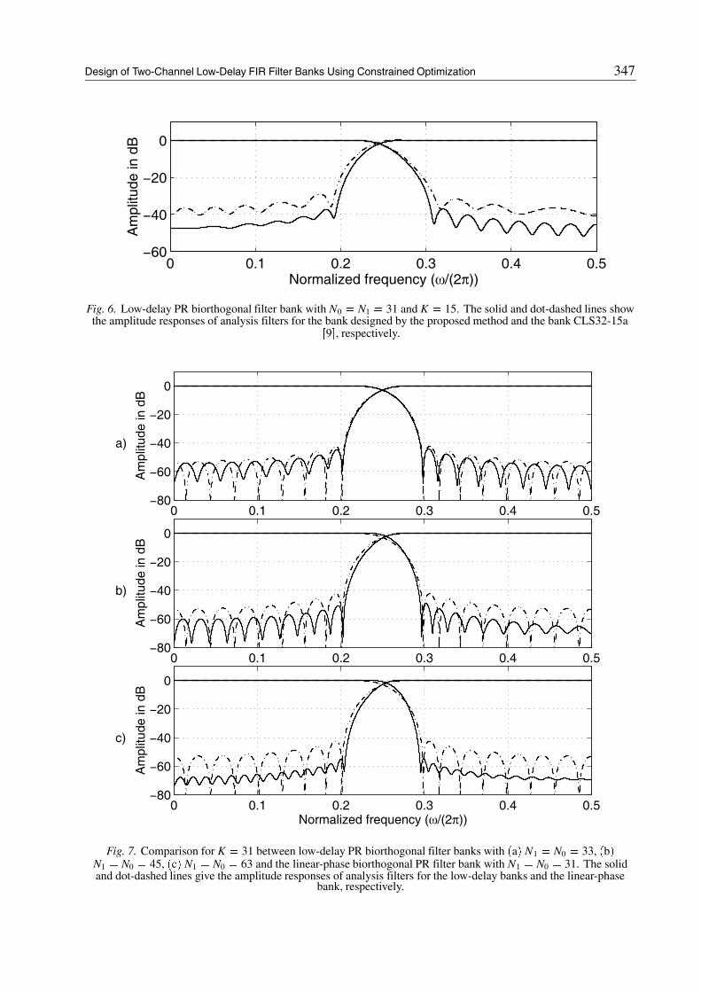
Fig. 6. Low-delay PR biorthogonal filter bank with N0 � N1 � 31 and K � 15. The solid and dot-dashed lines showthe amplitude responses of analysis filters for the bank designed by the proposed method and the bank CLS32-15a
�9�, respectively.
0 0.1 0.2 0.3 0.4 0.5−80
−60
−40
−20
0
Am
plitu
de in
dB
a)
0 0.1 0.2 0.3 0.4 0.5−80
−60
−40
−20
0
Am
plitu
de in
dB
b)
0 0.1 0.2 0.3 0.4 0.5−80
−60
−40
−20
0
Normalized frequency (ω/(2π))
Am
plitu
de in
dB
c)
Fig. 7. Comparison for K � 31 between low-delay PR biorthogonal filter banks with �a� N1 � N0 � 33, �b�N1 � N0 � 45, �c� N1 � N0 � 63 and the linear-phase biorthogonal PR filter bank with N1 � N0 � 31. The solidand dot-dashed lines give the amplitude responses of analysis filters for the low-delay banks and the linear-phase
bank, respectively.
348 Design of Two-Channel Low-Delay FIR Filter Banks Using Constrained Optimization
Example 4. It is desired to design low-delayPR biorthogonal filter banks for K � 31, δp �
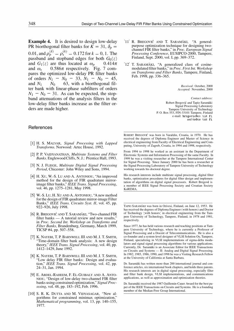
0�01, and ρ�k�p � ρ�k�s � 0�172 for k � 0, 1. Thepassband and stopband edges for both G0�z�and G1�z� are thus located at ωp � 0�414πand ωs � 0�586π respectively. Fig. 7 com-pares the optimized low-delay PR filter banksof orders N1 � N0 � 33, N1 � N0 � 45,and N1 � N0 � 63, with a biorthogonal fil-ter bank with linear-phase subfilters of ordersN1 � N0 � 31. As can be expected, the stop-band attenuations of the analysis filters in thelow-delay filter banks increase as the filter or-ders are made higher.
References
�1� H. S. MALVAR, Signal Processing with LappedTransforms. Norwood: Artec House, 1992.
�2� P. P. VAIDYANATHAN, Multirate Systems and FilterBanks. EnglewoodCliffs, N. J.: Prentice Hall, 1993.
�3� N. J. FLIEGE, Multirate Digital Signal ProcessingPeriod, Chicester: John Wiley and Sons, 1994.
�4� H. XU, W.-S. LU AND A. ANTONIOU, “An improvedmethod for the design of FIR quadrature mirror-image filter banks,” IEEE Trans. Signal Processing,vol. 46, pp. 1275–1281, May 1998.
�5� W.-S. LU, H. XU AND A. ANTONIOU, “A new methodfor the design of FIR quadrature mirror-image FilterBanks,” IEEE Trans. Circuits Syst. II, vol. 45, pp.922–926, July 1998.
�6� R. BREGOVIC AND T. SARAMAKI, “Two-channel FIRfilter banks — A tutorial review and new results,”in Proc. Second Int. Workshop on Transforms andFilter Banks, Brandenburg, Germany, March 1999,TICSP #4, pp. 507–558.
�7� K. NAYEBI, T. P. BARNWELL III AND M. J. T. SMITH,“Time-domain filter bank analysis: A new designtheory,” IEEE Trans. Signal Processing, vol. 40, pp.1412–1429, June 1992.
�8� K. NAYEBI, T. P. BARNWELL III AND M. J. T. SMITH,“Low delay FIR filter banks: Design and evalua-tion,” IEEE Trans. Signal Processing, vol. 42, pp.24–31, Jan. 1994.
�9� E. ABDEL-RAHEEM, F. EL-GUIBALY AND A. ANTO-NIOU, “Design of low-delay two-channel FIR filterbanks using constrained optimization,” Signal Proc-sssing, vol. 48, pp. 183–192, Feb. 1996.
�10� S. R. K. DUTTA AND M. VIDYASAGAR, “New al-gorithms for constrained minimax optimization,”Mathematical programming, vol. 13, pp. 140–155,1977.
�11� R. BREGOVIC AND T. SARAMAKI, “A general-purpose optimization technique for designing two-channel FIR filter banks,” in Proc. European SignalProcessing Conference, EUSIPCO-2000, Tampere,Finland, Sept. 2000, vol. I, pp. 369–372.
�12� T. SARAMAKI, “A generalized class of cosine-modulated filter banks,” in Proc. First Int. Workshopon Transforms and Filter Banks, Tampere, Finland,Feb. 1998, pp. 336–365.
Received: October, 2000Accepted: November, 2000
Contact address:
Robert Bregovic and Tapio SaramakiSignal Processing Laboratory
Tampere University of TechnologyP. O. Box 553, FIN-33101 Tampere, Finland
e-mail: bregovic�cs�tut�fiand ts�cs�tut�fi
ROBERT BREGOVIC was born in Varazdin, Croatia, in 1970. He hasreceived the degrees of Diploma Engineer and Master of Science inelectrical engineering from Faculty of Electrical Engineering and Com-puting, University of Zagreb, Croatia, in 1994 and 1998, respectively.
From 1994 to 1998 he worked as an assistant in the Department ofElectronic Systems and Information Processing of the same Faculty. In1999 he was a visiting researcher at the Tampere International Centerfor Signal Procesing. Since January 2000 he has been a researcher atthe Signal Processing Laboratory of Tampere University of Technologyworking towards his doctoral degree.
His research interests include multirate signal processing, digital filterbanks, optimization procedures for digital filter design and implemen-tation of algorithms on digital signal processors. Robert Bregovic isa member of IEEE Signal Processing Society and Croatian SocietyKoREMA.
TAPIO SARAMAKI was born in Orivesi, Finland, on June 12, 1953. Hehas received the degrees of Diploma Engineer �with honors� and Doctorof Technology �with honors� in electrical engineering from the Tam-pere University of Technology, Tampere, Finland, in 1978 and 1981,respectively.
Since 1977, he has held various research and teaching positions at Tam-pere University of Technology, where he is currently a Professor ofSignal Processing and a Docent of Telecommunications. He is also aco-founder and a system-level designer of VLSI Solution Oy, Tampere,Finland, specializing in VLSI implementations of sigma-delta modu-lators and signal signal processing algorithms for various applications.Currently, Dr. Saramaki is an Associate Editor for IEEE Transactionson Circuits and Systems — II: Analog and Digital Signal Processing.In 1982, 1985, 1986, 1990, and 1998 he was a Visiting Research Fellowat the University of California at Santa Barbara.
Dr. Saramaki has written more than 200 international journal and con-ference articles, six international book chapters, and holds three patents.His research interests are in digital signal processing, especially filterand filter bank design, VLSI implementations, and communicationsapplications, as well as approximation and optimization theories.
Dr. Saramaki received the 1987 Guillemin-Cauer Award for the best pa-per of the IEEE Transactions on Circuits and Systems. He is a foundingmember of the Median-Free Group International.
Related Documents