Contents lists available at ScienceDirect Structures journal homepage: www.elsevier.com/locate/structures Design of Truss Structures Through Reuse Jan Brütting a, ⁎ , Joseph Desruelle a , Gennaro Senatore b , Corentin Fivet a a Structural Xploration Lab, Swiss Federal Institute of Technology (EPFL), Passage du Cardinal 13b, 1700 Fribourg, Switzerland b Applied Computing and Mechanics Laboratory, Swiss Federal Institute of Technology (EPFL), Station 18, 1015 Lausanne, Switzerland ARTICLEINFO Keywords: Structural optimization Truss structures Circular economy Reuse Life-Cycle Assessment ABSTRACT This paper presents structural optimization techniques to design truss structures that make best use of a given stock of structural components. Still little explored, the reuse of structural components over multiple service lives has the potential to significantly reduce the environmental impact of building structures. Structural design and construction based on reuse avoids sourcing new material, it reduces superfluous waste, and requires little energy. However, designing a structure from a stock of reclaimed elements entails a change of design paradigm: in contrast to conventional design practice, the structural geometry and topology depends on element stock characteristics, e.g. available cross sections and lengths. This paper presents discrete structural optimization formulations to design truss systems from stock elements. The approach taken in this work is iterative: 1) ele- ment assignment and topology optimization are carried out, and 2) geometry optimization follows thereafter to best-fit the system geometry to the length of assigned stock elements, for instance to reduce cut-off waste. Two case studies are presented: a) a cantilever of simple layout used to explain the details of the design methodology, and b) a train station roof structure of complex layout made from elements reused from disassembled electric pylons. For these case studies, Life Cycle Assessment confirms that an up to 63% environmental impact reduction is possible when comparing structures obtained with the proposed method against weight-optimized solutions made of new elements. 1. Introduction 1.1. Reuse and circular economy The building sector is a major contributor to material consumption [1], energy use, greenhouse gas emission [2], and waste production [3]. Most of the embodied impacts of buildings [4], e.g. related to material extraction, production, construction and demolition, are due to load bearing systems [5]. A way to reduce these building embodied impacts is to apply the principles of circular economy [6]. In a circular economy, manufactured goods are kept in use as long as possible through closed loops, which consist of: 1) repair, 2) reuse, and 3) recycling. Recycling is the common strategy to make use of obsolete con- struction materials but it involves energy for reprocessing (e.g. melting steel scrap). Instead, reuse has the potential to reduce building en- vironmental impacts further with respect to recycling because less en- ergy is spent for reprocessing [2,7]. This paper focuses on the direct reuse of structural components, involving their relocation and re- purpose. In this context, reused structural elements will have a longer service life and disassembled buildings become a mine for new con- structions [7]. A holistic approach to component reuse involves careful deconstruction as well as the storage, refurbishment and quality as- sessment of structural elements [7,8]. A recently built example of such design philosophy based on reuse is the BedZED project - a residential and office building whose steel structure is made of 90% locally reclaimed elements [9]. Another ex- ample is the London Olympic stadium roof truss that incorporates 2500 tons of reused steel pipeline tubes which were tested prior to reuse in order to assess the material quality [2]. A theoretical case study to design a railway station roof made of truss modules reclaimed from deconstructed industrial buildings and combined with new steel ele- ments is presented in [10]. The reuse of such truss modules allowed saving 30% of embodied energy and carbon compared to a new steel structure [10]. Even though significant environmental savings are possible through reuse [7], it has been shown that reusing steel elements can be more expensive in monetary terms than using new steel because of the de- construction and refurbishment processes involved [11,12]. It was identified in [7] and [12] that the potential establishment of element stocks, databases and a market for reused elements will facilitate greater reuse in the future. https://doi.org/10.1016/j.istruc.2018.11.006 Received 14 September 2018; Received in revised form 6 November 2018; Accepted 7 November 2018 ⁎ Corresponding author at: Structural Xploration Lab, IA ENAC EPFL, smart living lab, Passage du Cardinal 13b, 1700 Fribourg, Switzerland. E-mail address: jan.bruetting@epfl.ch (J. Brütting). Structures 18 (2019) 128–137 Available online 10 November 2018 2352-0124/ © 2018 The Authors. Published by Elsevier Ltd on behalf of Institution of Structural Engineers. This is an open access article under the CC BY-NC-ND license (http://creativecommons.org/licenses/BY-NC-ND/4.0/). T

Welcome message from author
This document is posted to help you gain knowledge. Please leave a comment to let me know what you think about it! Share it to your friends and learn new things together.
Transcript
Contents lists available at ScienceDirect
Structures
journal homepage: www.elsevier.com/locate/structures
Design of Truss Structures Through ReuseJan Brüttinga,⁎, Joseph Desruellea, Gennaro Senatoreb, Corentin Fivetaa Structural Xploration Lab, Swiss Federal Institute of Technology (EPFL), Passage du Cardinal 13b, 1700 Fribourg, SwitzerlandbApplied Computing and Mechanics Laboratory, Swiss Federal Institute of Technology (EPFL), Station 18, 1015 Lausanne, Switzerland
A R T I C L E I N F O
Keywords:Structural optimizationTruss structuresCircular economyReuseLife-Cycle Assessment
A B S T R A C T
This paper presents structural optimization techniques to design truss structures that make best use of a givenstock of structural components. Still little explored, the reuse of structural components over multiple service liveshas the potential to significantly reduce the environmental impact of building structures. Structural design andconstruction based on reuse avoids sourcing new material, it reduces superfluous waste, and requires littleenergy. However, designing a structure from a stock of reclaimed elements entails a change of design paradigm:in contrast to conventional design practice, the structural geometry and topology depends on element stockcharacteristics, e.g. available cross sections and lengths. This paper presents discrete structural optimizationformulations to design truss systems from stock elements. The approach taken in this work is iterative: 1) ele-ment assignment and topology optimization are carried out, and 2) geometry optimization follows thereafter tobest-fit the system geometry to the length of assigned stock elements, for instance to reduce cut-off waste. Twocase studies are presented: a) a cantilever of simple layout used to explain the details of the design methodology,and b) a train station roof structure of complex layout made from elements reused from disassembled electricpylons. For these case studies, Life Cycle Assessment confirms that an up to 63% environmental impact reductionis possible when comparing structures obtained with the proposed method against weight-optimized solutionsmade of new elements.
1. Introduction
1.1. Reuse and circular economy
The building sector is a major contributor to material consumption[1], energy use, greenhouse gas emission [2], and waste production [3].Most of the embodied impacts of buildings [4], e.g. related to materialextraction, production, construction and demolition, are due to loadbearing systems [5]. A way to reduce these building embodied impactsis to apply the principles of circular economy [6]. In a circular economy,manufactured goods are kept in use as long as possible through closedloops, which consist of: 1) repair, 2) reuse, and 3) recycling.
Recycling is the common strategy to make use of obsolete con-struction materials but it involves energy for reprocessing (e.g. meltingsteel scrap). Instead, reuse has the potential to reduce building en-vironmental impacts further with respect to recycling because less en-ergy is spent for reprocessing [2,7]. This paper focuses on the directreuse of structural components, involving their relocation and re-purpose. In this context, reused structural elements will have a longerservice life and disassembled buildings become a mine for new con-structions [7]. A holistic approach to component reuse involves careful
deconstruction as well as the storage, refurbishment and quality as-sessment of structural elements [7,8].
A recently built example of such design philosophy based on reuse isthe BedZED project - a residential and office building whose steelstructure is made of 90% locally reclaimed elements [9]. Another ex-ample is the London Olympic stadium roof truss that incorporates2500 tons of reused steel pipeline tubes which were tested prior to reusein order to assess the material quality [2]. A theoretical case study todesign a railway station roof made of truss modules reclaimed fromdeconstructed industrial buildings and combined with new steel ele-ments is presented in [10]. The reuse of such truss modules allowedsaving 30% of embodied energy and carbon compared to a new steelstructure [10].
Even though significant environmental savings are possible throughreuse [7], it has been shown that reusing steel elements can be moreexpensive in monetary terms than using new steel because of the de-construction and refurbishment processes involved [11,12]. It wasidentified in [7] and [12] that the potential establishment of elementstocks, databases and a market for reused elements will facilitategreater reuse in the future.
https://doi.org/10.1016/j.istruc.2018.11.006Received 14 September 2018; Received in revised form 6 November 2018; Accepted 7 November 2018
⁎ Corresponding author at: Structural Xploration Lab, IA ENAC EPFL, smart living lab, Passage du Cardinal 13b, 1700 Fribourg, Switzerland.E-mail address: [email protected] (J. Brütting).
Structures 18 (2019) 128–137
Available online 10 November 20182352-0124/ © 2018 The Authors. Published by Elsevier Ltd on behalf of Institution of Structural Engineers. This is an open access article under the CC BY-NC-ND license (http://creativecommons.org/licenses/BY-NC-ND/4.0/).
T
Notation
Variable Unit Description
a∈ ℝs [m2] vector of stock element cross section areasB∈ ℝd×m [−] equilibrium matrixb [m] buffer on the available element lengthC [kgCO2eq] total embodied carbonD∈ ℝd×m [m] matrix to account for self-weight of the struc-
tured [−] number of unsupported degrees of freedomE [MJ] total embodied energye∈ ℝs [MPa] vector of stock element Young's modulif∈ ℝd [MN] vector of static external forcesi [−] truss member position ij [−] stock element group jk [−] kth load casel∈ ℝs [m] vector of stock element lengthsl ∈ ℝm [m] vector of truss member lengthsm [−] total number of truss member positionsn∈ ℝs [−] vector of stock element availabilitiesp∈ ℝm [MN] vector of truss member forcespi, jbuck. [MN] buckling resistance of element j assigned at
truss position iρ∈ ℝs [kg/m3] vector of stock element densitiess [−] total number of stock element groupsσ∈ ℝs [MPa] vector of stock element yield strengthsT∈ {0,1}m×s [−] binary assignment matrixu∈ ℝd [m] vector of nodal displacementsumin ∈ ℝd [m] lower bound on the nodal displacementumax ∈ ℝd [m] upper bound on the nodal displacementsx∈ ℝd [m] vector of coordinates for unsupported truss
nodesy∈ ℝs [MN/m3] vector of stock element specific weights
1.2. Structural design
Reuse involves reversing the conventional structural design process,because the synthesis of a structural layout (geometry and topology) isconstrained by mechanical and geometric properties of an availablestock of elements [13]. This paper presents applications of structuraloptimization methods previously developed by the authors [14] todesign structures through reuse.
Optimization is often employed to obtain optimal layouts of struc-tures under a given set of boundary conditions and constraints [15].Truss structures are usually optimized by adjusting the topologystarting from a ground structure [16], which is the set of all possiblemember positions between the truss nodes. The member cross sectionsizes are part of the design variables. Simultaneously [17] or sequen-tially [18], the node positions can also be changed in order to obtain anoptimal truss geometry. To reduce optimization complexity, often crosssection areas are treated as continuous variables. In practice, becauseonly a limited set of standard cross sections is available, discrete sizingoptimization should be employed [19]. Discrete sizing and topologyoptimization has been formulated as a Mixed-Integer Linear Program-ming (MILP) problem in [20] and [21]. A MILP problem can be solvedto global optimality employing combinatorial optimization techniquessuch as branch-and-cut methods [22]. Usually, optimization of trussstructures is carried out assuming that all elements can be fabricatedwith required cross sections and lengths. Conversely, when reusingstructural elements from a stock, the number of available cross sectiontypes is restricted and the structure geometry has to best-fit availableelement lengths.
Structural optimization with stock constraints has received littleattention so far. The optimization of plane frames of fixed topologyfrom a stock of onetime available cross sections is presented in [23],
where evolutionary algorithms have been employed for weight opti-mization but without accounting for available element lengths. Strate-gies based on algorithms developed to solve bin-packing problems havebeen employed to form-fit a stock of wood logs to statically determinatetrusses in [24].
1.3. Outline
Section 2 summarizes an optimization approach for reticulatedstructures subject to a constraining element stock. This approachcombines 1) discrete structural topology optimization methods to selectan optimal subset of stock elements (Sections 2.1 and 2.2), with 2)geometry optimization methods to optimally match structure geometryand stock element dimensions (Section 2.3). Section 2.4 introduces anextension to this method to obtain improved solutions. Section 3 pre-sents the main assumptions of a Life Cycle Assessment that is employedto quantify environmental impacts and savings through reuse. Section 4describes two case studies: a) a cantilever truss of simple layout toexplain in detail the design methodology (Section 4.1), and b) a trainstation roof structure of complex layout reusing elements from a rea-listic set of disassembled electric pylons (Section 4.2).
2. Structural optimization with stock constraints
2.1. Element assignment
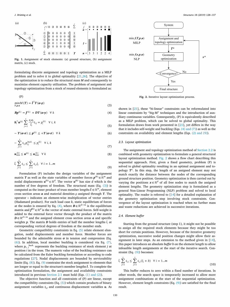
The selection of suitable elements from a stock and their optimalplacement in a structure can be formulated as an assignment problemwhich is of combinatorial nature. This is comparable to the selection ofcross sections in discrete sizing optimization methods [20,21]. Fig. 1(a)shows a weight optimized cantilever truss obtained from the groundstructure shown by the dashed lines (m=5 potential bar positions) andusing the stock illustrated in Fig. 1(c). The stock comprises s=6 ele-ment groups which are characterized by material properties (i.e.Young's moduli e∈ ℝs, material strengths σ∈ ℝs, material densitiesρ∈ ℝs, specific weights y∈ ℝs), cross-section areas a∈ ℝs, elementlengths l∈ ℝs and the element availabilities n∈ ℝs.
The assignment of one element from stock group j at position i in thestructure, is represented by an entry ti,j=1 in the binary assignmentmatrix T∈ {0, 1}m×s, shown in Fig. 1(b). For clarity, the system to-pology is changed when no element is assigned at a certain position,corresponding to a row of zeros in the assignment matrix. The in-equalities (Eqs. (1) and (2)) ensure maximally one assignment per po-sition i and limit the selection of bars to the number of available ele-ments for each group j:
= …=
t i m1 1j
s
i j1
,(1)
= …=
t n j s1i
m
i j j1
,(2)
t i j{0, 1} ,i j,
2.2. Structural assignment and topology optimization problem
The assignment problem described in Section 2.1 is included into astructural optimization formulation using a Simultaneous ANalysis andDesign (SAND) [25] approach. Different to Nested ANalysis and Design(NAND) where design sensitivity analysis is performed at each iterationof the optimization, SAND formulations simultaneously treat designvariables (e.g. cross section areas) as well as state variables (e.g. in-ternal forces and nodal displacements) as variables of the mathematicalprogramming procedure [25,26]. The SAND approach is key to allow
J. Brütting et al. Structures 18 (2019) 128–137
129
formulating discrete assignment and topology optimization as a MILPproblem and to solve it to global optimality [21,26]. The objective ofthe optimization is to reduce the structural mass M and consequently tomaximize element capacity utilization. The problem of assignment andtopology optimization from a stock of reused elements is formulated as:
(P)
=T l T aminM ( ) ¯ ( )T p u
T, , (3)
= +Bp f DT a y k( )k k( ) ( ) (4)
==
b ue a
lt p i k¯ ,i
T k
j
sj j
ii j i
k( )
1,
( )
(5)
+T a p T a k( ) ( )k( ) (6)
=t p p i k,
j
s
i j i jbuck
ik
1, ,
. ( )
(7)
u u u kmink k
maxk( ) ( ) ( ) (8)
= …= =
l t t l i m¯ 1ij
s
i jj
s
i j j1
,1
,(9)
Formulation (P) includes the design variables of the assignmentmatrix T as well as the state variables of member forces p(k) ∈ ℝm andnodal displacements u(k) ∈ ℝd. The vector u(k) has size d which is thenumber of free degrees of freedom. The structural mass (Eq. (3)) iscomputed as the inner product of truss member lengths l ∈ ℝm, elementcross section areas a and material densities ρ assigned through T. Theoperator ∘ indicates an element-wise multiplication of vector entries(Hadamard product). For each load case k, static equilibrium of forcesat the nodes is ensured by Eq. (4), where B∈ ℝd×m is the equilibriummatrix and f(k) ∈ ℝd is the vector of static external forces. Self-weight isadded to the external force vector through the product of the matrixD∈ ℝd×m and the assigned element cross section areas a and specificweights y. The matrix D holds entries of half the member lengths li atcorresponding vertical degrees of freedom at the member ends.
Geometric compatibility constraints in Eq. (5) relate element elon-gation, nodal displacements and member force. Member forces arebounded by the admissible stress σ in tension and compression (Eq.(6)). In addition, local member buckling is considered via Eq. (7),where pi, jbuck. represents the buckling resistance of stock element j atposition i in the truss. The numeric value of the buckling resistance canbe calculated from the Euler buckling formulation or according to coderegulations [27]. Nodal displacements are bounded by serviceabilitylimits (Eq. (8)). Eq. (9) constrains the stock assignment to elements thatare longer or equal to the structure's member lengths l . To complete theoptimization formulation, the assignment and availability constraintsintroduced in previous Section 2.1 must hold (Eqs. (1) and (2)).
The objective function and all constraints of (P) are linear, exceptthe compatibility constraints (Eq. (5)) which contain products of binaryassignment variables ti,j and continuous displacement variables u. As
shown in [21], these “bi-linear” constraints can be reformulated intolinear constraints by “big-M” techniques and the introduction of aux-iliary continuous variables. Consequently, (P) is equivalently describedas a MILP problem, which can be solved to global optimality. Thisformulation draws from work presented in [21], yet differs in the waythat it includes self-weight and buckling (Eqs. (4) and (7)) as well as theconstraints on availability and element lengths (Eqs. (2) and (9)).
2.3. Layout optimization
The assignment and topology optimization method of Section 2.2 iscombined with geometry optimization to formulate a general structurallayout optimization method. Fig. 2 shows a flow chart describing thissequential approach. First, given a fixed geometry, problem (P) issolved to global optimality resulting in an optimal assignment and to-pology T*. In this step, the length of an assigned element may notmatch exactly the distance between the nodes of the correspondingground structure position. Geometry optimization is then carried out byvarying the positions x∈ ℝd of all free nodes to match the assignedelement lengths. The geometry optimization step is formulated as ageneral Non-Linear Programming (NLP) problem and solved to localoptimality. The reader is referred to [14] for a detailed explanation ofthe geometry optimization step involving stock constraints. Con-vergence of the layout optimization is reached when no further massand waste reductions are achieved in successive iterations.
2.4. Element buffer
Starting from the ground structure (step 1), it might not be possibleto assign all the required stock elements because they might be tooshort for certain positions. However, because of the iterative geometryoptimization, successive nodal position changes might allow their as-signment in later steps. As an extension to the method given in [14],this paper introduces an absolute buffer b on the element length to allowinfeasible length assignments at the start of the iterative search. Con-straint (Eq. (9)) becomes:
+ = …= =
l t t l b i m¯ ( ) 1ij
s
i jj
s
i j j1
,1
,(10)
This buffer reduces to zero within a fixed number of iterations. Inother words, the search space is temporarily increased to allow moreassignment combinations at the start of the sequential optimization.However, element length constraints (Eq. (9)) are satisfied for the finalresult.
Fig. 1. Assignment of stock elements: (a) ground structure, (b) assignmentmatrix, (c) stock.
System
Assignment and topology optimization
min f(T,p,u)MILP
min f(x,p,u)NLP
Geometryoptimization
Convergence?
Final structure
T*
No
Yes
x*
Fig. 2. Iterative layout optimization process.
J. Brütting et al. Structures 18 (2019) 128–137
130
3. Embodied energy and carbon
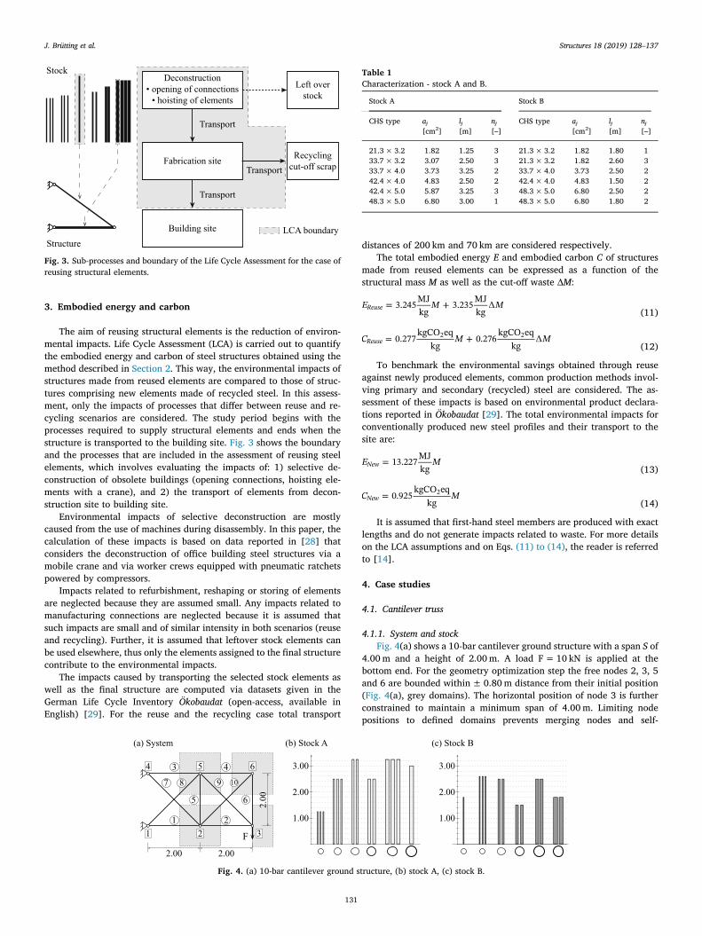
The aim of reusing structural elements is the reduction of environ-mental impacts. Life Cycle Assessment (LCA) is carried out to quantifythe embodied energy and carbon of steel structures obtained using themethod described in Section 2. This way, the environmental impacts ofstructures made from reused elements are compared to those of struc-tures comprising new elements made of recycled steel. In this assess-ment, only the impacts of processes that differ between reuse and re-cycling scenarios are considered. The study period begins with theprocesses required to supply structural elements and ends when thestructure is transported to the building site. Fig. 3 shows the boundaryand the processes that are included in the assessment of reusing steelelements, which involves evaluating the impacts of: 1) selective de-construction of obsolete buildings (opening connections, hoisting ele-ments with a crane), and 2) the transport of elements from decon-struction site to building site.
Environmental impacts of selective deconstruction are mostlycaused from the use of machines during disassembly. In this paper, thecalculation of these impacts is based on data reported in [28] thatconsiders the deconstruction of office building steel structures via amobile crane and via worker crews equipped with pneumatic ratchetspowered by compressors.
Impacts related to refurbishment, reshaping or storing of elementsare neglected because they are assumed small. Any impacts related tomanufacturing connections are neglected because it is assumed thatsuch impacts are small and of similar intensity in both scenarios (reuseand recycling). Further, it is assumed that leftover stock elements canbe used elsewhere, thus only the elements assigned to the final structurecontribute to the environmental impacts.
The impacts caused by transporting the selected stock elements aswell as the final structure are computed via datasets given in theGerman Life Cycle Inventory Ökobaudat (open-access, available inEnglish) [29]. For the reuse and the recycling case total transport
distances of 200 km and 70 km are considered respectively.The total embodied energy E and embodied carbon C of structures
made from reused elements can be expressed as a function of thestructural mass M as well as the cut-off waste ∆M:
= +E M M3.245 MJkg
3.235 MJkgReuse (11)
= +C M M0.277 kgCO eqkg
0.276 kgCO eqkgReuse
2 2
(12)
To benchmark the environmental savings obtained through reuseagainst newly produced elements, common production methods invol-ving primary and secondary (recycled) steel are considered. The as-sessment of these impacts is based on environmental product declara-tions reported in Ökobaudat [29]. The total environmental impacts forconventionally produced new steel profiles and their transport to thesite are:
=E M13.227 MJkgNew (13)
=C M0.925 kgCO eqkgNew
2
(14)
It is assumed that first-hand steel members are produced with exactlengths and do not generate impacts related to waste. For more detailson the LCA assumptions and on Eqs. (11) to (14), the reader is referredto [14].
4. Case studies
4.1. Cantilever truss
4.1.1. System and stockFig. 4(a) shows a 10-bar cantilever ground structure with a span S of
4.00m and a height of 2.00m. A load F=10 kN is applied at thebottom end. For the geometry optimization step the free nodes 2, 3, 5and 6 are bounded within±0.80m distance from their initial position(Fig. 4(a), grey domains). The horizontal position of node 3 is furtherconstrained to maintain a minimum span of 4.00m. Limiting nodepositions to defined domains prevents merging nodes and self-
Fig. 3. Sub-processes and boundary of the Life Cycle Assessment for the case ofreusing structural elements.
Fig. 4. (a) 10-bar cantilever ground structure, (b) stock A, (c) stock B.
Table 1Characterization - stock A and B.
Stock A Stock B
CHS type aj lj nj CHS type aj lj nj[cm2] [m] [–] [cm2] [m] [–]
21.3× 3.2 1.82 1.25 3 21.3× 3.2 1.82 1.80 133.7× 3.2 3.07 2.50 3 21.3× 3.2 1.82 2.60 333.7× 4.0 3.73 3.25 2 33.7× 4.0 3.73 2.50 242.4× 4.0 4.83 2.50 2 42.4× 4.0 4.83 1.50 242.4× 5.0 5.87 3.25 3 48.3× 5.0 6.80 2.50 248.3× 5.0 6.80 3.00 1 48.3× 5.0 6.80 1.80 2
J. Brütting et al. Structures 18 (2019) 128–137
131
overlapping of the structure. In practice, the constraining domains alsoallow to obtain optimal structure geometries that remain close to aninitial design intention or input.
Two stock configurations A and B are illustrated in Fig. 4(b) and (c).The two stocks consist of steel bars with circular hollow sections (CHS) ofdimensions taken from EN 10220 [30]. It is assumed that all steel bars havea yield strength of 235MPa, a Young's modulus of 210GPa and a density of7850 kg/m3. Table 1 summarizes cross-section types and areas as well aselement lengths and availabilities for each group in stocks A and B.
4.1.2. ResultsFour cases for the optimization of the cantilever truss are con-
sidered: (a) pure assignment and topology optimization from stock A;(b) layout optimization without element buffer from stock A; (c) and (d)layout optimization with element buffer from stock A and B respec-tively. In addition to these cases with reused elements, two benchmarkscenarios for weight-optimized structures made of newly produced steelelements with equivalent material properties are considered. Thesebenchmark cases are: (e) a sequential discrete cross section and
0
5
10
15
20
25
0
50
100
150
200
250
Em
bodi
ed C
arbo
n [k
gCO
2eq]
Em
bodi
ed E
nerg
y [M
J]
Embodied Energy Embodied Carbon Transport share
(a) (b) (c) (d) (e) (f)
(a) (b) (c) (d) (e) (f)
0
20
40
60
80
100
0
10
20
30
40
50
Mea
n el
emen
t util
izat
ion
[%]
Stru
ctur
e m
ass
and
was
te [
kg]
Structure Waste Utilization
Reuse New
Fig. 6. Comparison between structures: (a) to (d) made from reused elements, (e) and (f) made of new steel.
1
12 3 5
7 9
2
3
7 9
5
(a) Stock A
12
3
7 95
(d) Stock B
2 13 7 9
5
S
S
1
2
3
79
5
(c) Stock A
1 23 7 9
5
S
1 2
3
79
5
(b) Stock A
12 3 5
7 9
S
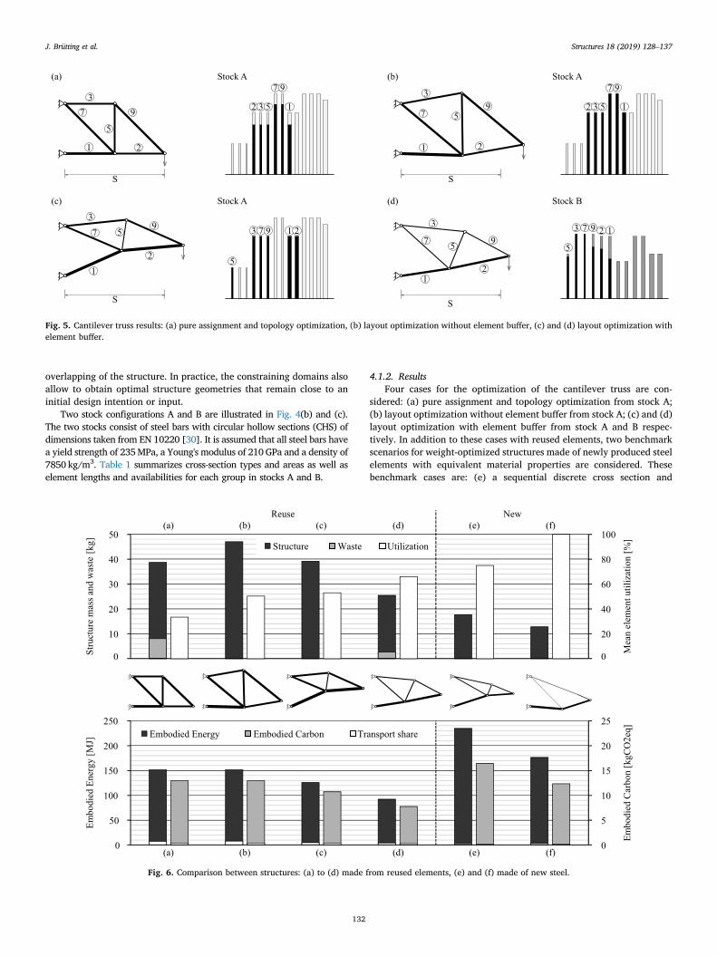
Fig. 5. Cantilever truss results: (a) pure assignment and topology optimization, (b) layout optimization without element buffer, (c) and (d) layout optimization withelement buffer.
J. Brütting et al. Structures 18 (2019) 128–137
132
geometry optimization allowing all standard CHS sections reported inEN 10220 [30], and (f) a simultaneous cross section and geometryoptimization in which cross section radii are continuous design vari-ables and the wall thickness is set to 10% of the radius. In case (e),during the geometry optimization step compliance is minimizedwhereas during the sizing optimization step weight minimization is theobjective. For case (f) the objective is weight minimization. All casesconsider a critical Euler buckling capacity (Eq. (7)).
Fig. 5 shows the optimal structural systems as well as the use of thestock for the cases (a) – (d) involving reuse. In the stock illustrations,
black bars represent system members and grey bars unused stock ele-ments or cut-off. In addition, Fig. 6 shows obtained results for all cases,including (e) and (f). Case (a) results in the biggest cut-off waste ∆M of8.00 kg, whereas cases (b) and (c) achieve zero waste because of geo-metry optimization. Case (d) achieves the lowest mass amongst all thestructures made from reused elements because stock B has a largeravailability of small sections than stock A. In cases (a) and (b), smallcross sections cannot be used because of their short length. In case (c),the assignment of a small cross section at position ⑤ is possible via theelement buffer technique described in Section 2.4. The element bufferalso allows obtaining an optimal solution in case (d) where all stockelements are shorter than the initial ground structure diagonals.
The bar chart at the top of Fig. 6 further indicates the mean capacityutilization of all truss members. Obviously, using lighter stock elementsresults in an increased utilization – for example compare cases (b) and(c). As stock B contains elements with smaller cross sections than stockA, the capacity utilization in case (d) is even higher than in case (c). Inbenchmark case (e) all cross sections reported in EN 10220 [30] areavailable in infinite quantity, allowing for a lighter structural system.Nevertheless, the discrete nature of the sizing problem results in amaximum utilization of 75%. Only the members in benchmark case (f),in which the cross section areas are treated as continuous variables,reach full capacity utilization and by that achieve the lightest structure.In general, member capacity utilization indicates that reusing structuralelements can result in oversized structures when there is a limitedavailability of small cross sections.
4.1.3. Embodied impact savingsThe embodied energy and carbon of the systems made from reused
elements are compared to those of weight-optimized structures madefrom newly produced elements following the method introduced inSection 3. The bar chart at the bottom of Fig. 6 shows that reusingstructural elements results in a significant reduction of embodiedcarbon and energy, even though these systems have a higher mass andlower mean capacity utilization. The environmental impacts due to thetransportation of elements are small compared to the remaining sharescaused by selective deconstruction for the reuse cases (a) to (d) or bynew production for the benchmark cases (e) and (f).
4.2. A train station roof designed from power transmission pylons
This case study proposes a structural scheme for the main trainstation roof in Lausanne (Vaud, Switzerland) using elements reclaimedfrom power transmission pylons. The redesign of Lausanne's train
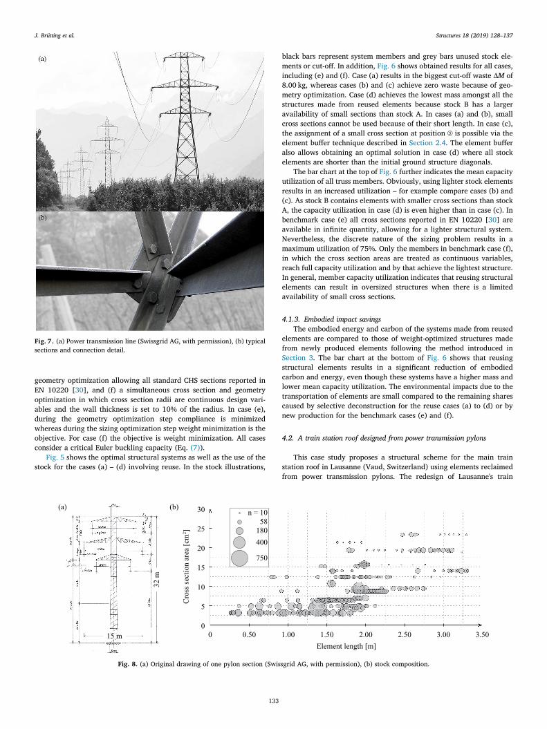
Fig. 8. (a) Original drawing of one pylon section (Swissgrid AG, with permission), (b) stock composition.
Fig. 7. (a) Power transmission line (Swissgrid AG, with permission), (b) typicalsections and connection detail.
J. Brütting et al. Structures 18 (2019) 128–137
133
station is currently under planning to respond to an increase in pas-senger demand. The pylons, shown in Fig. 7(a), were built in the 1950sin the region of Wallis, Switzerland. Six power transmission lines con-sisting of such pylons are scheduled to be replaced by one high voltageline. However, the pylon members have not yet reached the service lifefor which they had been designed.
4.2.1. Stock characterizationThe pylons consist of L-section steel bars connected by plates and
bolts as shown in Fig. 7(b). The power line operator Swissgrid AG in-tends to disassemble the pylons piece by piece. Fig. 8(a) shows one ofthe archive plans that have been used to quantify the number of ele-ments within one transmission line as well as their mechanical
S = 18.40 m
1.30
13.2
0
5.20
18.40 18.40 18.40
End unit(a) (b)
Fa
H
Fb
Fc Fc FcFbFd
Central unit Global domain Local domain
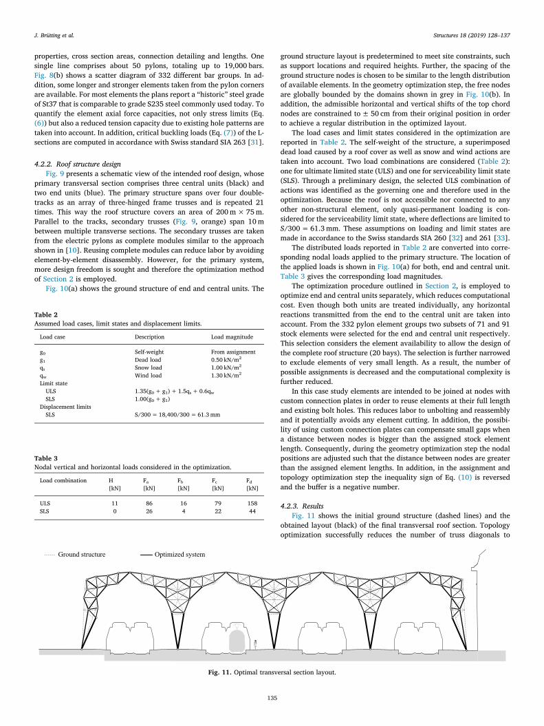
Fig. 10. Transversal section: (a) ground structure and loads, (b) geometry optimization domains.
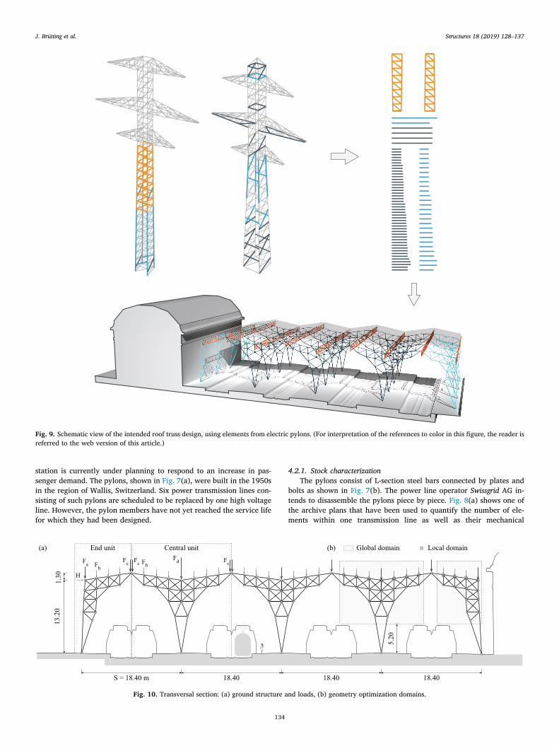
Fig. 9. Schematic view of the intended roof truss design, using elements from electric pylons. (For interpretation of the references to color in this figure, the reader isreferred to the web version of this article.)
J. Brütting et al. Structures 18 (2019) 128–137
134
properties, cross section areas, connection detailing and lengths. Onesingle line comprises about 50 pylons, totaling up to 19,000 bars.Fig. 8(b) shows a scatter diagram of 332 different bar groups. In ad-dition, some longer and stronger elements taken from the pylon cornersare available. For most elements the plans report a “historic” steel gradeof St37 that is comparable to grade S235 steel commonly used today. Toquantify the element axial force capacities, not only stress limits (Eq.(6)) but also a reduced tension capacity due to existing hole patterns aretaken into account. In addition, critical buckling loads (Eq. (7)) of the L-sections are computed in accordance with Swiss standard SIA 263 [31].
4.2.2. Roof structure designFig. 9 presents a schematic view of the intended roof design, whose
primary transversal section comprises three central units (black) andtwo end units (blue). The primary structure spans over four double-tracks as an array of three-hinged frame trusses and is repeated 21times. This way the roof structure covers an area of 200m×75m.Parallel to the tracks, secondary trusses (Fig. 9, orange) span 10mbetween multiple transverse sections. The secondary trusses are takenfrom the electric pylons as complete modules similar to the approachshown in [10]. Reusing complete modules can reduce labor by avoidingelement-by-element disassembly. However, for the primary system,more design freedom is sought and therefore the optimization methodof Section 2 is employed.
Fig. 10(a) shows the ground structure of end and central units. The
ground structure layout is predetermined to meet site constraints, suchas support locations and required heights. Further, the spacing of theground structure nodes is chosen to be similar to the length distributionof available elements. In the geometry optimization step, the free nodesare globally bounded by the domains shown in grey in Fig. 10(b). Inaddition, the admissible horizontal and vertical shifts of the top chordnodes are constrained to± 50 cm from their original position in orderto achieve a regular distribution in the optimized layout.
The load cases and limit states considered in the optimization arereported in Table 2. The self-weight of the structure, a superimposeddead load caused by a roof cover as well as snow and wind actions aretaken into account. Two load combinations are considered (Table 2):one for ultimate limited state (ULS) and one for serviceability limit state(SLS). Through a preliminary design, the selected ULS combination ofactions was identified as the governing one and therefore used in theoptimization. Because the roof is not accessible nor connected to anyother non-structural element, only quasi-permanent loading is con-sidered for the serviceability limit state, where deflections are limited toS/300=61.3mm. These assumptions on loading and limit states aremade in accordance to the Swiss standards SIA 260 [32] and 261 [33].
The distributed loads reported in Table 2 are converted into corre-sponding nodal loads applied to the primary structure. The location ofthe applied loads is shown in Fig. 10(a) for both, end and central unit.Table 3 gives the corresponding load magnitudes.
The optimization procedure outlined in Section 2, is employed tooptimize end and central units separately, which reduces computationalcost. Even though both units are treated individually, any horizontalreactions transmitted from the end to the central unit are taken intoaccount. From the 332 pylon element groups two subsets of 71 and 91stock elements were selected for the end and central unit respectively.This selection considers the element availability to allow the design ofthe complete roof structure (20 bays). The selection is further narrowedto exclude elements of very small length. As a result, the number ofpossible assignments is decreased and the computational complexity isfurther reduced.
In this case study elements are intended to be joined at nodes withcustom connection plates in order to reuse elements at their full lengthand existing bolt holes. This reduces labor to unbolting and reassemblyand it potentially avoids any element cutting. In addition, the possibi-lity of using custom connection plates can compensate small gaps whena distance between nodes is bigger than the assigned stock elementlength. Consequently, during the geometry optimization step the nodalpositions are adjusted such that the distance between nodes are greaterthan the assigned element lengths. In addition, in the assignment andtopology optimization step the inequality sign of Eq. (10) is reversedand the buffer is a negative number.
4.2.3. ResultsFig. 11 shows the initial ground structure (dashed lines) and the
obtained layout (black) of the final transversal roof section. Topologyoptimization successfully reduces the number of truss diagonals to
Table 2Assumed load cases, limit states and displacement limits.
Load case Description Load magnitude
g0 Self-weight From assignmentg1 Dead load 0.50 kN/m2
qs Snow load 1.00 kN/m2
qw Wind load 1.30 kN/m2
Limit stateULS 1.35(g0+ g1)+ 1.5qs+ 0.6qwSLS 1.00(g0+ g1)
Displacement limitsSLS S/300=18,400/300=61.3mm
Table 3Nodal vertical and horizontal loads considered in the optimization.
Load combination H Fa Fb Fc Fd[kN] [kN] [kN] [kN] [kN]
ULS 11 86 16 79 158SLS 0 26 4 22 44
Ground structure Optimized system
Fig. 11. Optimal transversal section layout.
J. Brütting et al. Structures 18 (2019) 128–137
135
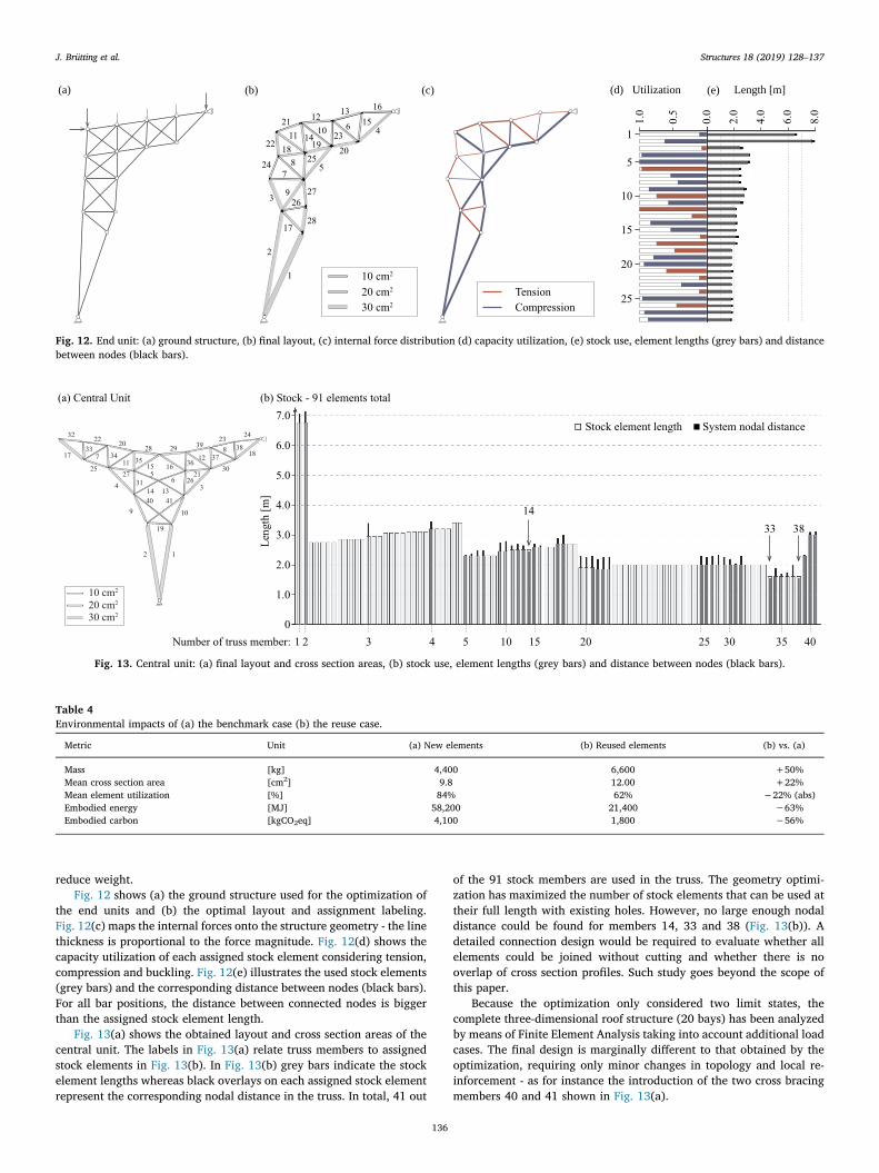
reduce weight.Fig. 12 shows (a) the ground structure used for the optimization of
the end units and (b) the optimal layout and assignment labeling.Fig. 12(c) maps the internal forces onto the structure geometry - the linethickness is proportional to the force magnitude. Fig. 12(d) shows thecapacity utilization of each assigned stock element considering tension,compression and buckling. Fig. 12(e) illustrates the used stock elements(grey bars) and the corresponding distance between nodes (black bars).For all bar positions, the distance between connected nodes is biggerthan the assigned stock element length.
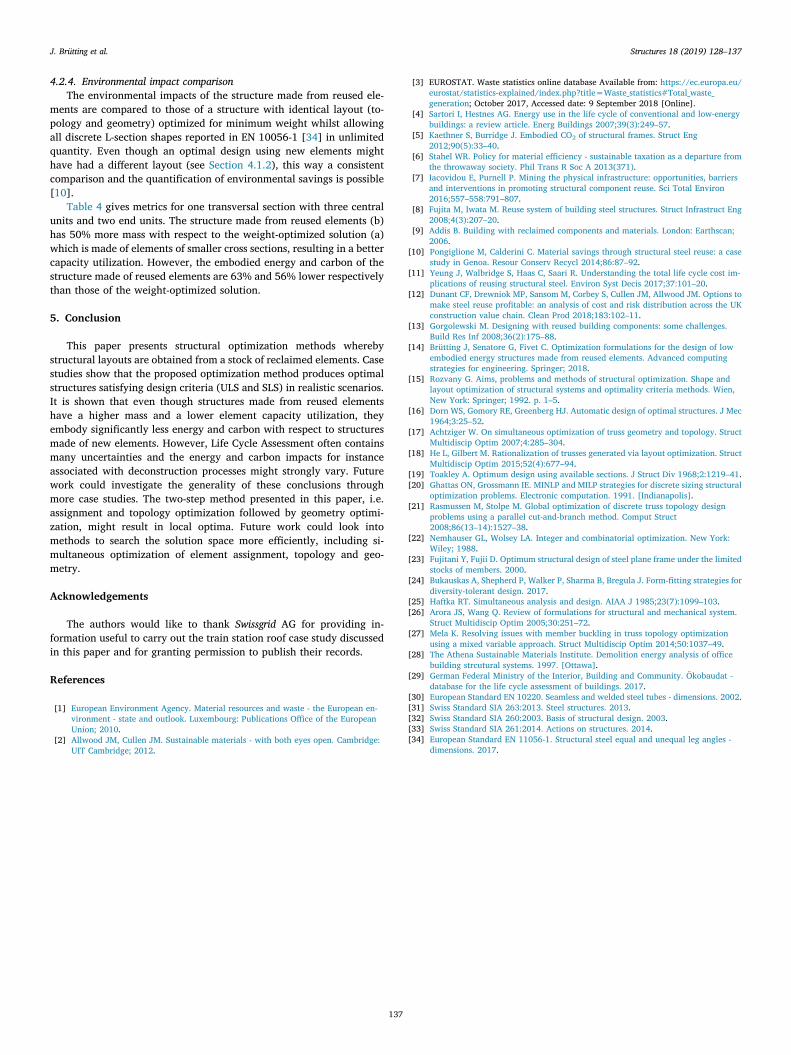
Fig. 13(a) shows the obtained layout and cross section areas of thecentral unit. The labels in Fig. 13(a) relate truss members to assignedstock elements in Fig. 13(b). In Fig. 13(b) grey bars indicate the stockelement lengths whereas black overlays on each assigned stock elementrepresent the corresponding nodal distance in the truss. In total, 41 out
of the 91 stock members are used in the truss. The geometry optimi-zation has maximized the number of stock elements that can be used attheir full length with existing holes. However, no large enough nodaldistance could be found for members 14, 33 and 38 (Fig. 13(b)). Adetailed connection design would be required to evaluate whether allelements could be joined without cutting and whether there is nooverlap of cross section profiles. Such study goes beyond the scope ofthis paper.
Because the optimization only considered two limit states, thecomplete three-dimensional roof structure (20 bays) has been analyzedby means of Finite Element Analysis taking into account additional loadcases. The final design is marginally different to that obtained by theoptimization, requiring only minor changes in topology and local re-inforcement - as for instance the introduction of the two cross bracingmembers 40 and 41 shown in Fig. 13(a).
Fig. 13. Central unit: (a) final layout and cross section areas, (b) stock use, element lengths (grey bars) and distance between nodes (black bars).
Table 4Environmental impacts of (a) the benchmark case (b) the reuse case.
Metric Unit (a) New elements (b) Reused elements (b) vs. (a)
Mass [kg] 4,400 6,600 +50%Mean cross section area [cm2] 9.8 12.00 +22%Mean element utilization [%] 84% 62% −22% (abs)Embodied energy [MJ] 58,200 21,400 −63%Embodied carbon [kgCO2eq] 4,100 1,800 −56%
0.0
1.0
0.5
2.0
4.0
6.0
8.0
10 cm2
20 cm2
30 cm2
TensionCompression
27
25
28
1
2
3
24
22
75
20
21
14
15
23
1213 16
4 1
5
10
15
20
25
61011
18 19
8
926
17
(a) (d) Utilization (e) Length [m](b) (c)
Fig. 12. End unit: (a) ground structure, (b) final layout, (c) internal force distribution (d) capacity utilization, (e) stock use, element lengths (grey bars) and distancebetween nodes (black bars).
J. Brütting et al. Structures 18 (2019) 128–137
136
4.2.4. Environmental impact comparisonThe environmental impacts of the structure made from reused ele-
ments are compared to those of a structure with identical layout (to-pology and geometry) optimized for minimum weight whilst allowingall discrete L-section shapes reported in EN 10056-1 [34] in unlimitedquantity. Even though an optimal design using new elements mighthave had a different layout (see Section 4.1.2), this way a consistentcomparison and the quantification of environmental savings is possible[10].
Table 4 gives metrics for one transversal section with three centralunits and two end units. The structure made from reused elements (b)has 50% more mass with respect to the weight-optimized solution (a)which is made of elements of smaller cross sections, resulting in a bettercapacity utilization. However, the embodied energy and carbon of thestructure made of reused elements are 63% and 56% lower respectivelythan those of the weight-optimized solution.
5. Conclusion
This paper presents structural optimization methods wherebystructural layouts are obtained from a stock of reclaimed elements. Casestudies show that the proposed optimization method produces optimalstructures satisfying design criteria (ULS and SLS) in realistic scenarios.It is shown that even though structures made from reused elementshave a higher mass and a lower element capacity utilization, theyembody significantly less energy and carbon with respect to structuresmade of new elements. However, Life Cycle Assessment often containsmany uncertainties and the energy and carbon impacts for instanceassociated with deconstruction processes might strongly vary. Futurework could investigate the generality of these conclusions throughmore case studies. The two-step method presented in this paper, i.e.assignment and topology optimization followed by geometry optimi-zation, might result in local optima. Future work could look intomethods to search the solution space more efficiently, including si-multaneous optimization of element assignment, topology and geo-metry.
Acknowledgements
The authors would like to thank Swissgrid AG for providing in-formation useful to carry out the train station roof case study discussedin this paper and for granting permission to publish their records.
References
[1] European Environment Agency. Material resources and waste - the European en-vironment - state and outlook. Luxembourg: Publications Office of the EuropeanUnion; 2010.
[2] Allwood JM, Cullen JM. Sustainable materials - with both eyes open. Cambridge:UIT Cambridge; 2012.
[3] EUROSTAT. Waste statistics online database Available from: https://ec.europa.eu/eurostat/statistics-explained/index.php?title=Waste_statistics#Total_waste_generation; October 2017, Accessed date: 9 September 2018 [Online].
[4] Sartori I, Hestnes AG. Energy use in the life cycle of conventional and low-energybuildings: a review article. Energ Buildings 2007;39(3):249–57.
[5] Kaethner S, Burridge J. Embodied CO2 of structural frames. Struct Eng2012;90(5):33–40.
[6] Stahel WR. Policy for material efficiency - sustainable taxation as a departure fromthe throwaway society. Phil Trans R Soc A 2013(371).
[7] Iacovidou E, Purnell P. Mining the physical infrastructure: opportunities, barriersand interventions in promoting structural component reuse. Sci Total Environ2016;557–558:791–807.
[8] Fujita M, Iwata M. Reuse system of building steel structures. Struct Infrastruct Eng2008;4(3):207–20.
[9] Addis B. Building with reclaimed components and materials. London: Earthscan;2006.
[10] Pongiglione M, Calderini C. Material savings through structural steel reuse: a casestudy in Genoa. Resour Conserv Recycl 2014;86:87–92.
[11] Yeung J, Walbridge S, Haas C, Saari R. Understanding the total life cycle cost im-plications of reusing structural steel. Environ Syst Decis 2017;37:101–20.
[12] Dunant CF, Drewniok MP, Sansom M, Corbey S, Cullen JM, Allwood JM. Options tomake steel reuse profitable: an analysis of cost and risk distribution across the UKconstruction value chain. Clean Prod 2018;183:102–11.
[13] Gorgolewski M. Designing with reused building components: some challenges.Build Res Inf 2008;36(2):175–88.
[14] Brütting J, Senatore G, Fivet C. Optimization formulations for the design of lowembodied energy structures made from reused elements. Advanced computingstrategies for engineering. Springer; 2018.
[15] Rozvany G. Aims, problems and methods of structural optimization. Shape andlayout optimization of structural systems and optimality criteria methods. Wien,New York: Springer; 1992. p. 1–5.
[16] Dorn WS, Gomory RE, Greenberg HJ. Automatic design of optimal structures. J Mec1964;3:25–52.
[17] Achtziger W. On simultaneous optimization of truss geometry and topology. StructMultidiscip Optim 2007;4:285–304.
[18] He L, Gilbert M. Rationalization of trusses generated via layout optimization. StructMultidiscip Optim 2015;52(4):677–94.
[19] Toakley A. Optimum design using available sections. J Struct Div 1968;2:1219–41.[20] Ghattas ON, Grossmann IE. MINLP and MILP strategies for discrete sizing structural
optimization problems. Electronic computation. 1991. [Indianapolis].[21] Rasmussen M, Stolpe M. Global optimization of discrete truss topology design
problems using a parallel cut-and-branch method. Comput Struct2008;86(13–14):1527–38.
[22] Nemhauser GL, Wolsey LA. Integer and combinatorial optimization. New York:Wiley; 1988.
[23] Fujitani Y, Fujii D. Optimum structural design of steel plane frame under the limitedstocks of members. 2000.
[24] Bukauskas A, Shepherd P, Walker P, Sharma B, Bregula J. Form-fitting strategies fordiversity-tolerant design. 2017.
[25] Haftka RT. Simultaneous analysis and design. AIAA J 1985;23(7):1099–103.[26] Arora JS, Wang Q. Review of formulations for structural and mechanical system.
Struct Multidiscip Optim 2005;30:251–72.[27] Mela K. Resolving issues with member buckling in truss topology optimization
using a mixed variable approach. Struct Multidiscip Optim 2014;50:1037–49.[28] The Athena Sustainable Materials Institute. Demolition energy analysis of office
building strcutural systems. 1997. [Ottawa].[29] German Federal Ministry of the Interior, Building and Community. Ökobaudat -
database for the life cycle assessment of buildings. 2017.[30] European Standard EN 10220. Seamless and welded steel tubes - dimensions. 2002.[31] Swiss Standard SIA 263:2013. Steel structures. 2013.[32] Swiss Standard SIA 260:2003. Basis of structural design. 2003.[33] Swiss Standard SIA 261:2014. Actions on structures. 2014.[34] European Standard EN 11056-1. Structural steel equal and unequal leg angles -
dimensions. 2017.
J. Brütting et al. Structures 18 (2019) 128–137
137
Related Documents