Design of the HLPR Chair Design of the HLPR Chair Home Lift Position and Rehabilitation Chair Roger Bostelman James Albus Intelligent Systems Division Manufacturing Engineering Laboratory National Institute of Standards and Technology June 19, 2007 1 of 88

Welcome message from author
This document is posted to help you gain knowledge. Please leave a comment to let me know what you think about it! Share it to your friends and learn new things together.
Transcript
Design of the HLPR Chair
Design of the HLPR Chair Home Lift Position and Rehabilitation Chair
Roger Bostelman James Albus
Intelligent Systems Division
Manufacturing Engineering Laboratory National Institute of Standards and Technology
June 19, 2007
1 of 88
Design of the HLPR Chair
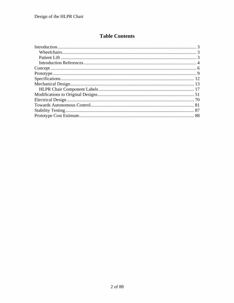
Table Contents
Introduction......................................................................................................................... 3
Wheelchairs..................................................................................................................... 3 Patient Lift ...................................................................................................................... 3 Introduction References .................................................................................................. 4
Concept ............................................................................................................................... 6 Prototype ............................................................................................................................. 9 Specifications.................................................................................................................... 12 Mechanical Design............................................................................................................ 13
HLPR Chair Component Labels ................................................................................... 17 Modifications to Original Designs.................................................................................... 51 Electrical Design............................................................................................................... 70 Towards Autonomous Control.......................................................................................... 81 Stability Testing................................................................................................................ 87 Prototype Cost Estimate.................................................................................................... 88
2 of 88

Design of the HLPR Chair
Introduction Reference [1] says “today, approximately 10 percent of the world’s population is over
60; by 2050 this proportion will have more than doubled” and “the greatest rate of increase is amongst the oldest old, people aged 85 and older.” She follows by adding that this group is subject to both physical and cognitive impairments more than younger people. These facts have a profound impact on how the world will maintain the elderly independent as long as possible from caregivers. Both physical and cognitive diminishing abilities address the body and the mental process of knowing, including aspects such as awareness, perception, reasoning, intuition and judgment. Assistive technology for the mobility impaired includes the wheelchair, lift aids and other devices, all of which have been around for decades. However, the patient typically or eventually requires assistance to use the device; whether it’s someone to push them in a wheelchair, to lift them from the bed to a chair or to the toilet or for guiding them through cluttered areas. With fewer caregivers and more elderly, there is a need for improving these devices to provide them independent assistance.
Wheelchairs There has been an increasing need for wheelchairs over time. L.H.V. van der Woude
[2] states that mobility is fundamental to health, social integration and individual well-being of the humans. Henceforth, mobility must be viewed as being essential to the outcome of the rehabilitation process of wheelchair dependent persons and to their successful (re-)integration into society and to a productive and active life. Thrun [3] said that, if possible, rehabilitation to relieve the dependence on the wheelchair is ideal for this type of patient to live a longer, healthier life. Van der Woude continues stating that many lower limb disabled subjects depend upon a wheelchair for their mobility. Estimated numbers for Europe and USA are respectively 2.5 million and 1.25 million. The quality of the wheelchair, the individual work capacity, the functionality of the wheelchair/user combination, and the effectiveness of the rehabilitation program do indeed determine the freedom of mobility.
Patient Lift Just as important as wheelchairs are the lift devices and people who lift patients into
wheelchairs and other seats, beds, automobiles, etc. The need for patient lift devices will also increase as generations get older. When considering if there is a need for patient lift devices, several references state the positive, for example: • “The question is, what does it cost not to buy this equipment? A back injury can cost
as much as $50,000, and that’s not even including all the indirect costs. If a nursing home can buy these lifting devices for $1,000 to $2,000, and eliminate a back injury that costs tens of thousands of dollars, that’s a good deal,” [4]
• 1 in every 3 nurses become injured from the physical exertion put forth while moving non-ambulatory patients; costing their employers $35,000 per injured nurse. [5]
• 1 in 2 non-ambulatory patients fall to the floor and become injured when being transferred from a bed to a wheelchair. - [6]
• "Nursing and personal care facilities are a growing industry where hazards are known
3 of 88

Design of the HLPR Chair
and effective controls are available," said OSHA Administrator John Henshaw. "The industry also ranks among the highest in terms of injuries and illnesses, with rates about 2 1⁄2 times that of all other general industries..." [7]
• “Already today there are over 400,000 unfilled nursing positions causing healthcare providers across the country to close wings or risk negative outcomes. Over the coming years, the declining ratio of working age adults to elderly will further exacerbate the shortage. In 1950 there were 8 adults available to support each elder 65+, today the ratio is 5:1 and by 2020 the ratio will drop to 3 working age adults per elder person.” [8]
In 2005, NIST ISD began the Healthcare Mobility Project to target this staggering
healthcare issue of patient lift and mobility. ISD researchers looked at currently available technology through a survey of patient lift and mobility devices [9]. That report showed that there is need for technology that includes mobility devices that can lift and maneuver patients to other seats and technology that can provide for rehabilitation to help the patient become independent of the wheelchair.
An additional area investigated in the survey was intelligent wheelchairs. NIST has been studying intelligent mobility for the military, transportation, and the manufacturing industry for nearly 30 years through the Intelligent Control of Mobility Systems (ICMS) Program. [10] Toward a standard control system architecture and advanced 3D imaging technologies, as being researched within the ICMS Program, and applying them to intelligent wheelchairs, NIST has begun outfitting the HLPR Chair with computer controls. Although throughout the world there are or have been many research efforts in intelligent wheelchairs, including: [11, 12, 13, 14] and many others, the authors could find no sources applying standard control methods nor application of the most advanced 3D imagers prototyped today to intelligent wheelchairs. Therefore, NIST began developing the HLPR Chair [15] to investigate these specific areas of mobility, lift and rehabilitation, as well as advanced autonomous control.
This paper includes mechanical and electrical designs for the HLPR Chair in its prototype stage with designs dating back to December 2005. An initial prototype HLPR Chair concept, called RoboChair, was completed in July 2004.
Introduction References [1] Pollack, Martha, “Intelligent Technology for Adaptive Aging” Presentation, AAAI-04 American Association for Artificial Intelligence Conference Keynote Address, 2004 [2] L.H.V. van der Woude , M.T.E. Hopman and C.H. van Kemenade, “Biomedical Aspects of Manual Wheelchair Propulsion: The State of the Art II,” Volume 5, Assistive Technology Research Series, 1999, 392 pp., hardcover [3] Thrun, Sebastian, Visit to Stanford University to discuss healthcare mobility devices, August 2006. [4] Marras, William, “Lifting Patients Poses High Risk for Back Injuries,” Ohio State University, http://researchnews.osu.edu/archive/resthome.htm. 1999. [5] Blevins, Healthcare Statistics: Blevins Medical, Inc., http://www.patientlift.net/282164.html. 2006 [6]U.S. Bureau of Labor Statistics, from Blevins website: http://www.patientlift.net/282164.html, 1994.
4 of 88

Design of the HLPR Chair
[7] John Henshaw, http://www.osha.gov/SLTC/ nursinghome/solutions.html, Occupational Safety and Health Administration, 2005 [8] Wasatch Digital iQ, “InTouch Health's Remote Presence Robot Used by Healthcare Experts,” http://www.wasatchdigitaliq.com/parser.php?nav=article&article_id=43, Santa Barbara, CA & Salt Lake City --(Business Wire)--June 16, 2003. [9] Bostelman, Roger; Albus, James, “Survey of Patient Mobility and Lift Technologies Toward Advancements and Standards” NISTIR #7384, 2006. [10] NIST Intelligent Control of Mobility Systems Program website: http://www.isd.mel.nist.gov/ research_areas/mobility/index.htm [11] Kuno, Y., Murashima, T., Shimada, N., Shirai, Y., "Intelligent Wheelchair Remotely Controlled by Interactive Gestures," International Conference on Pattern Recognition, vol. 04, no. 4, p. 4672, 2000. [12] Patel, S., Jung, S-H., Ostrowski, J., Rao, R., Taylor, C., “Sensor based door navigation for a nonholonomic vehicle,” GRASP Laboratory, University of Pennsylvania, Proceedings of the 2002 IEEE International Conference on Robotics and Automation, Washington, DC, May 2002. [13] Song W.-K.; Lee H.; Bien Z., “KAIST - KARES: Intelligent wheelchair-mounted robotic arm system using vision and force sensor,” Robotics and Autonomous Systems, vol. 28, no. 1, pp. 83-94(12), 31, Publisher: Elsevier Science, July 1999. [14] Yanco, H., Hazel, A., Peacock, A., Smith, S. and Wintermute, H. “Initial Report on Wheelesley: A Robotic Wheelchair System,” Department of Computer Science, Wellesley College, 1995 [15] Bostelman, R., Albus, J., “HLPR Chair – A Service Robot for the Healthcare Industry,” 3rd International Workshop on Advances in Service Robotics, Vienna, Austria, July 7, 2006
5 of 88

Design of the HLPR Chair
Concept
(+/- 1.57 rad)
HLPR Chair is shown in the powered chair configuration with controls that the
patient can use to drive the chair or a nurse/caregiver can use the controls
from behind the chair to mobilize the patient.
Top view of the HLPR Chair rear steering and drive wheel and fixed front
casters configuration.
(a)
6 of 88
Design of the HLPR Chair
(b)
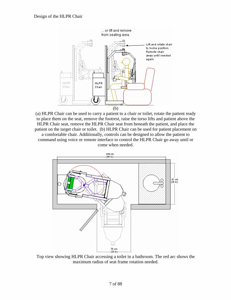
(a) HLPR Chair can be used to carry a patient to a chair or toilet, rotate the patient ready to place them on the seat, remove the footrest, raise the torso lifts and patient above the HLPR Chair seat, remove the HLPR Chair seat from beneath the patient, and place the
patient on the target chair or toilet. (b) HLPR Chair can be used for patient placement on a comfortable chair. Additionally, controls can be designed to allow the patient to
command using voice or remote interface to control the HLPR Chair go away until or come when needed.
Top view showing HLPR Chair accessing a toilet in a bathroom. The red arc shows the
maximum radius of seat frame rotation needed.
7 of 88
Design of the HLPR Chair
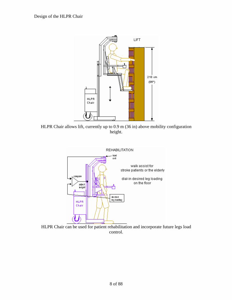
HLPR Chair allows lift, currently up to 0.9 m (36 in) above mobility configuration
height.
HLPR Chair can be used for patient rehabilitation and incorporate future legs load
control.
8 of 88

Design of the HLPR Chair
Prototype
3D imaging camera
Color camera
Load washer (future)
Outer L-Frame
Inner L-Frame
Rotation point
Torso lifts
Patient controls
Retractable seat
Retractable footrest
Lift Actuator
Casters
Steel forklift frame Wheel encoders (1 of 2) Rear Casters (only for anti-tip)
Drive/Steering motors and wheel
Batteries
Photograph 1 of the HLPR Chair prototype.
Photograph 2 (left) of the HLPR Chair in the mobility configuration showing the side
view and Photograph 3 (right) front view relative to a typical doorway.
9 of 88

Design of the HLPR Chair
Graphic showing the concept of placing a patient onto a toilet or chair with the HLPR Chair. The patient drives to the target seat (left), manually rotates near or over the seat
(middle) while the torso lifts support the patient and the seat retracts, and then is lowered onto the seat - toilet, chair or bed (right)
Photographs 4, 5, and 6 (lt. to rt.) of the HLPR Chair prototype in the same
configurations as in the graphic above placing a patient on a toilet.
Photograph 7 of the HLPR Chair prototype shown in the patient lift position.
10 of 88

Design of the HLPR Chair
Computer Computer interface electronics Existing Nurse controls and main relay electronic box Encoder (1 of 2)
Photograph 8 of the HLPR Chair with recently added front wheel encoders, development computer and interface electronics.
Padded Torso Lifts for under arms Seat and Footrest are retracted behind patient. Accessible controls Open frame base for walking
Photograph 9 of the HLPR Chair prototype in the rehabilitation/walking configuration. Summer Interns (Alex Page and Robert Vlacich) demonstrate the patient and nurse
configuration as part of their official duties.
11 of 88
Design of the HLPR Chair
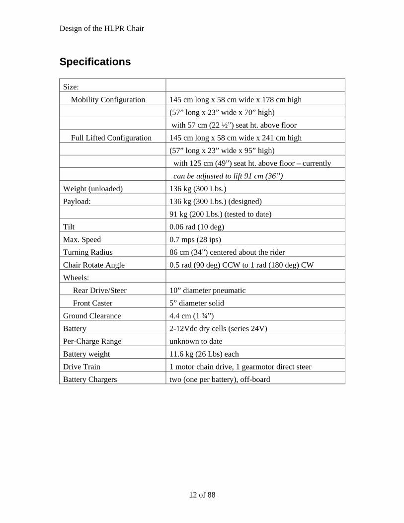
Specifications Size: Mobility Configuration 145 cm long x 58 cm wide x 178 cm high (57” long x 23” wide x 70” high) with 57 cm (22 ½”) seat ht. above floor Full Lifted Configuration 145 cm long x 58 cm wide x 241 cm high (57” long x 23” wide x 95” high) with 125 cm (49”) seat ht. above floor – currently can be adjusted to lift 91 cm (36”) Weight (unloaded) 136 kg (300 Lbs.) Payload: 136 kg (300 Lbs.) (designed) 91 kg (200 Lbs.) (tested to date) Tilt 0.06 rad (10 deg) Max. Speed 0.7 mps (28 ips) Turning Radius 86 cm (34”) centered about the rider Chair Rotate Angle 0.5 rad (90 deg) CCW to 1 rad (180 deg) CW Wheels: Rear Drive/Steer 10” diameter pneumatic Front Caster 5” diameter solid Ground Clearance 4.4 cm (1 ¾”) Battery 2-12Vdc dry cells (series 24V) Per-Charge Range unknown to date Battery weight 11.6 kg (26 Lbs) each Drive Train 1 motor chain drive, 1 gearmotor direct steer Battery Chargers two (one per battery), off-board
12 of 88

Design of the HLPR Chair
Mechanical Design Manual Fork Lift Base Frame1
Hydraulic Lift � Foot operated hydraulic pump makes raising the load a simple task. � Foot pedal release results in controlled lowering to reduce the risk of accidents. � Wheels are on swivel casters and lock into position for load lifting and lowering. � Two forks lower to 10.8 cm (4.3 in) above the floor and raise loads up to 137 cm (54 in) to get your machinery or heavy objects at an accessible level. � 227 kg (500 Lbs) capacity. For the HLPR Chair Design, the hydraulic piston was replaced with an electric ball screw actuator with 454 kg (1000 Lbs) lift capacity and 0.45 m (18 in) stroke. The fork lift chain design allows a 2:1 lift height for 0.9 m (36 in) fork (chair) lift with half the payload or 227 kg (500 Lbs).
1 NIST does not endorse products or organizations.
13 of 88
Design of the HLPR Chair
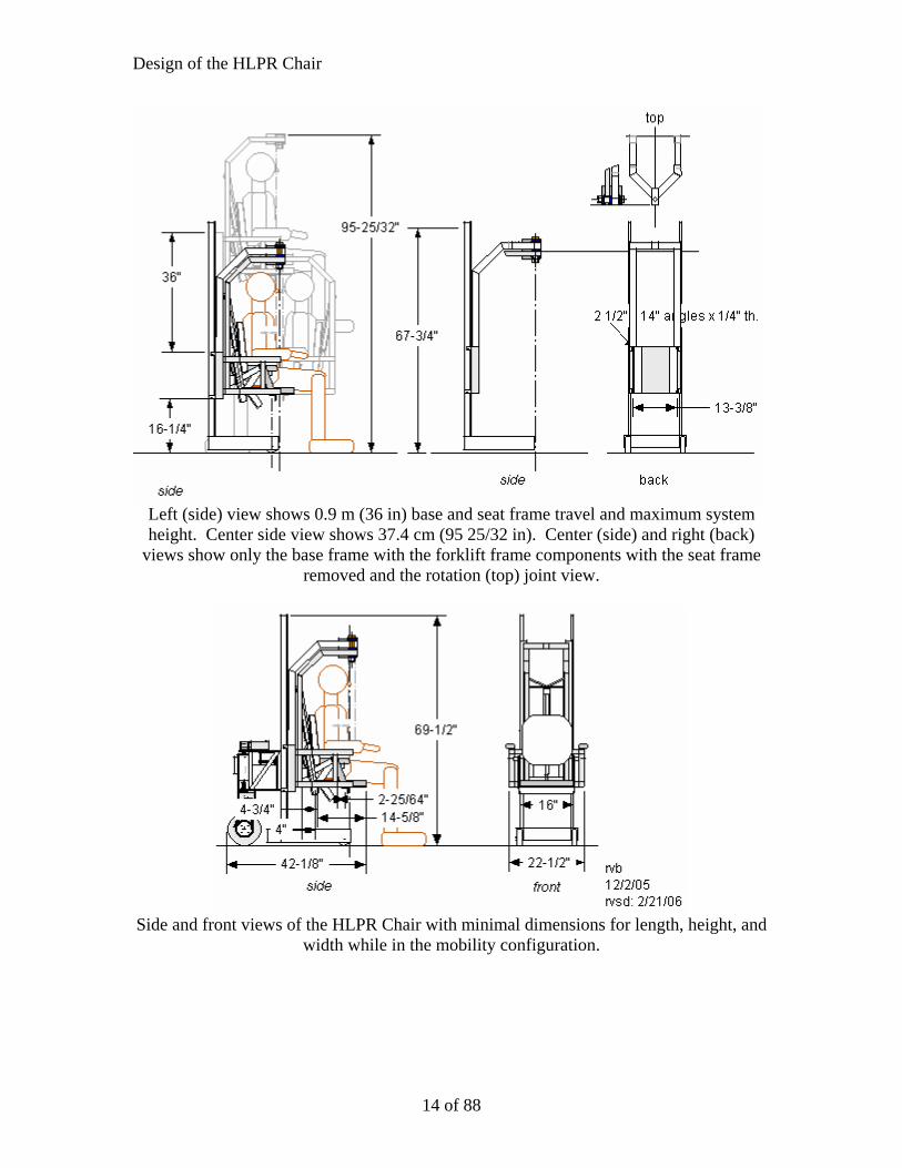
Left (side) view shows 0.9 m (36 in) base and seat frame travel and maximum system height. Center side view shows 37.4 cm (95 25/32 in). Center (side) and right (back)
views show only the base frame with the forklift frame components with the seat frame removed and the rotation (top) joint view.
Side and front views of the HLPR Chair with minimal dimensions for length, height, and
width while in the mobility configuration.
14 of 88
Design of the HLPR Chair
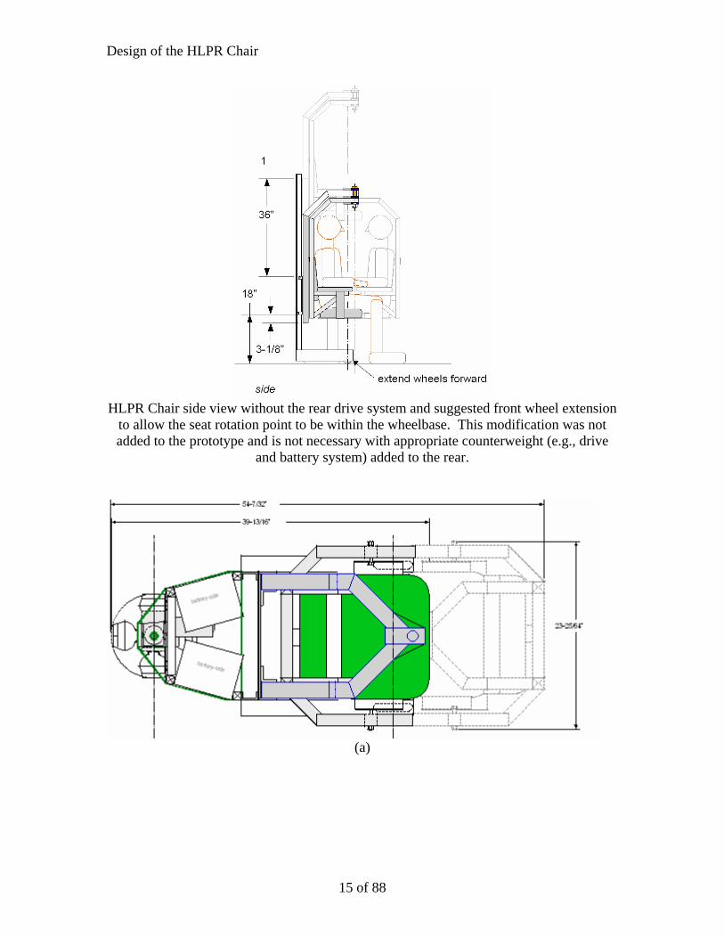
HLPR Chair side view without the rear drive system and suggested front wheel extension
to allow the seat rotation point to be within the wheelbase. This modification was not added to the prototype and is not necessary with appropriate counterweight (e.g., drive
and battery system) added to the rear.
(a)
15 of 88

Design of the HLPR Chair
(b) (c)
Top views of the HLPR Chair showing (a) Maximum length and width, (b) minimum HLPR Chair rotation about the front casters axle center 76 cm (30 in) and (c) top view of
the HLPR Chair.
16 of 88

Design of the HLPR Chair
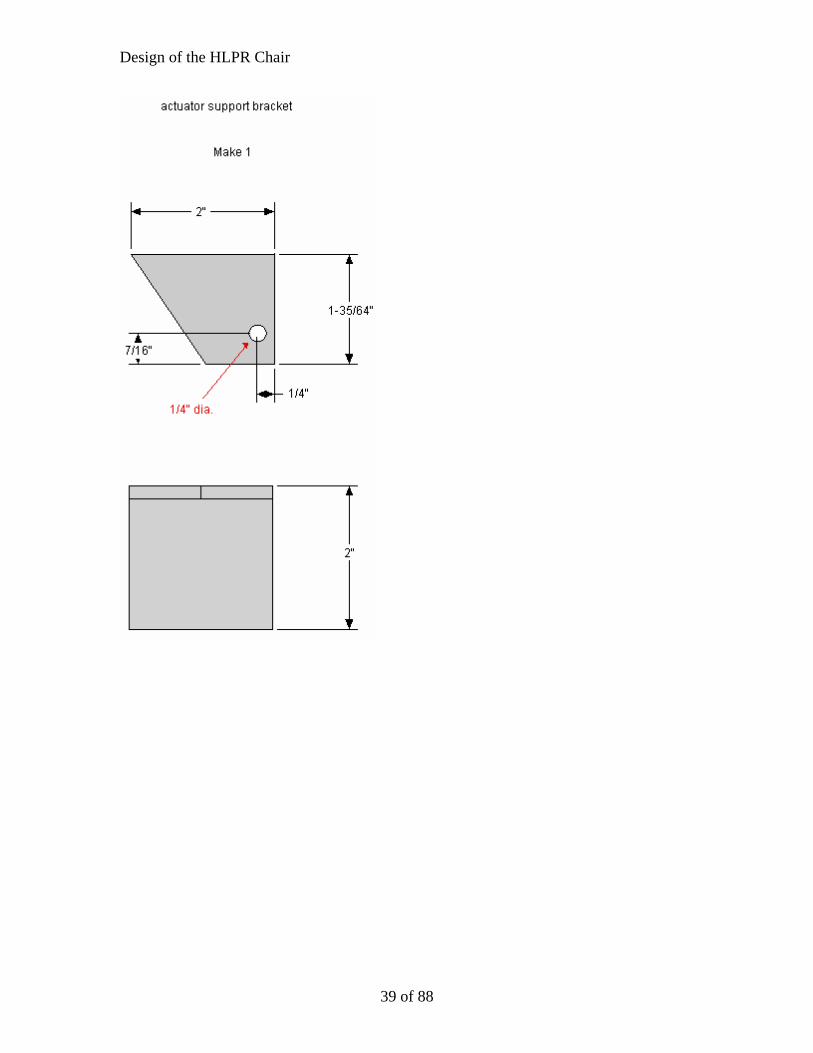
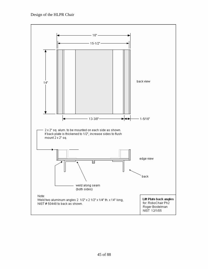
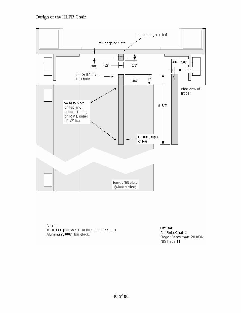
HLPR Chair Component Labels These labels refer to drawings that follow.
Frames pivot Seat frame assembly Base frame assembly Torso lifts Joystick Seat (rotated to standing position) Seat support Lift plate
Forklift frame Upper motor support plate Battery Lower motor support plate Axel plates Wheel assembly
17 of 88

Design of the HLPR Chair
38 cm
20.3 cm 16.5 cm
5.1 cm
10.1 cm
29.2 cm
33.0 cm
40.6 cm
18 of 88

Design of the HLPR Chair
37.0 cm
40.6 cm
20.3 cm 3.8 cm
10.1 cm 5.1 cm 29.2 cm
33.0 cm
19 of 88

Design of the HLPR Chair
Top axel plate Side axel plate (1 of 2) Wheel / tire Sprocket Bearing (1 of 2) Coupling nuts (1 of 4)
Front view of wheel assembly
(component drawings for this assembly follow)
20 of 88

Design of the HLPR Chair
11.9 cm
18.3 cm
3.5 cm
0.8 cm
3.8 cm
3.8 cm
7.6 cm
1 cm
21 of 88

Design of the HLPR Chair
10.2 cm
0.8 cm 5.6 cm
11.9 cm
0.5 cm
15.2 cm
14.8 cm
0.5 cm
1 cm
22 of 88
Design of the HLPR Chair
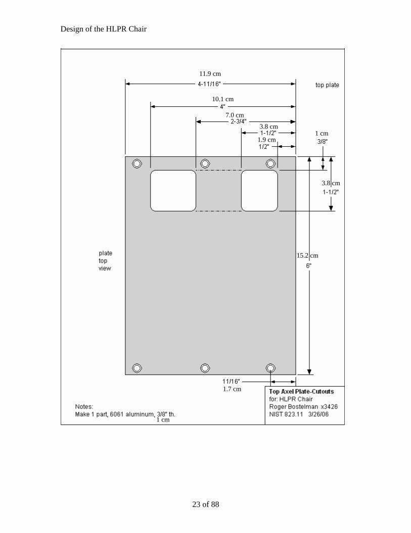
11.9 cm
10.1 cm
7.0 cm
3.8 cm 1 cm
1.9 cm
3.8 cm
15.2 cm
1.7 cm
1 cm
23 of 88
Design of the HLPR Chair
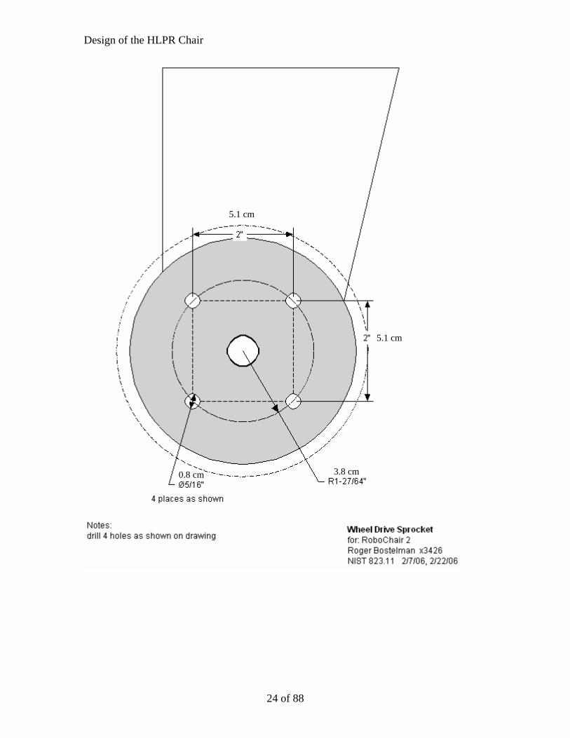
5.1 cm
5.1 cm
3.8 cm 0.8 cm
24 of 88
Design of the HLPR Chair
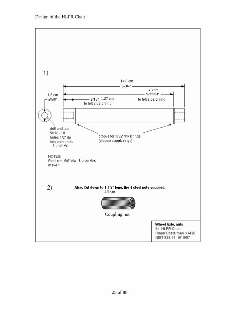
14.6 cm
13.3 cm 1.6 cm
1.27 cm
1.3 cm dp
1.6 cm dia.
3.8 cm
Coupling nut
25 of 88

Design of the HLPR Chair
Replaced steering motor with 93 W (1/8th Hp) gearmotor.
(86 cm/sec)
29.2cm
2.5 cm squ. alum. posts (4 each)
80.5 cmSpeed reducer mount
(following drawing)
See Top Axel Plate Cutouts drawing.
26 of 88

Design of the HLPR Chair
27 of 88

Design of the HLPR Chair
28 of 88
Design of the HLPR Chair
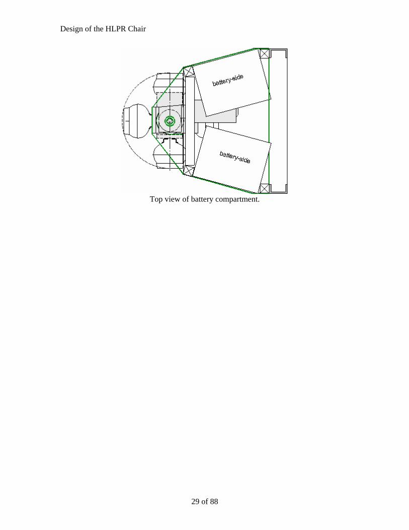
Top view of battery compartment.
29 of 88

Design of the HLPR Chair
30 of 88

Design of the HLPR Chair
31 of 88

Design of the HLPR Chair
Rear Cover
32 of 88
Design of the HLPR Chair
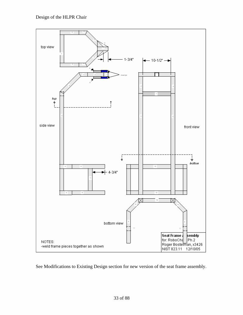
See Modifications to Existing Design section for new version of the seat frame assembly.
33 of 88

Design of the HLPR Chair
See Modifications to Existing Design section for new version of the base frame assembly.
34 of 88
Design of the HLPR Chair
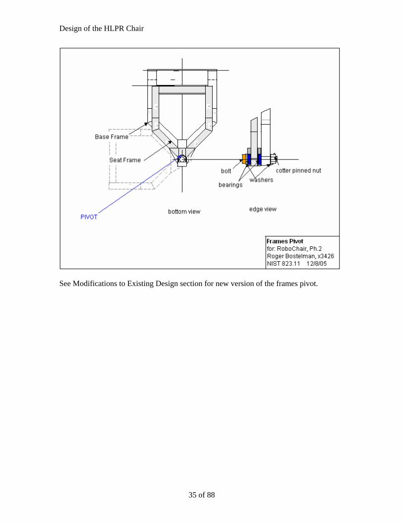
See Modifications to Existing Design section for new version of the frames pivot.
35 of 88

Design of the HLPR Chair
36 of 88
Design of the HLPR Chair
37 of 88

Design of the HLPR Chair
38 of 88
Design of the HLPR Chair
39 of 88

Design of the HLPR Chair
40 of 88

Design of the HLPR Chair
41 of 88

Design of the HLPR Chair
42 of 88

Design of the HLPR Chair
43 of 88

Design of the HLPR Chair
44 of 88
Design of the HLPR Chair
45 of 88
Design of the HLPR Chair
46 of 88

Design of the HLPR Chair
47 of 88

Design of the HLPR Chair
48 of 88

Design of the HLPR Chair
49 of 88

Design of the HLPR Chair
50 of 88
Design of the HLPR Chair
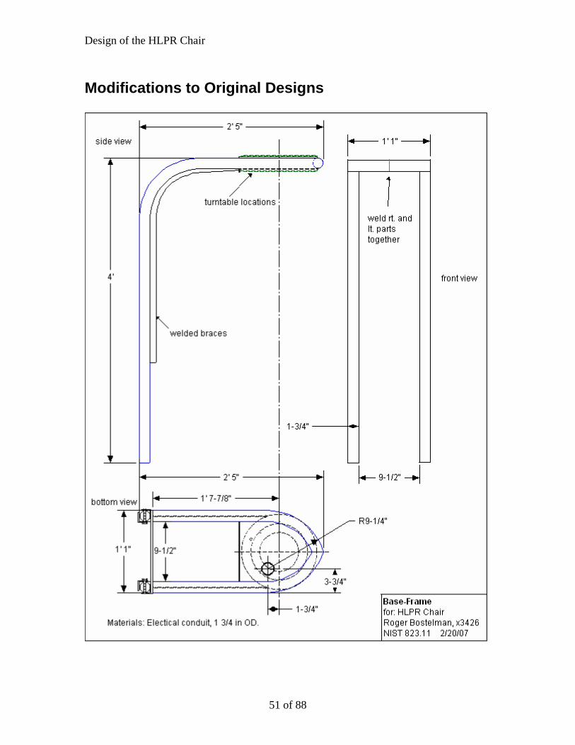
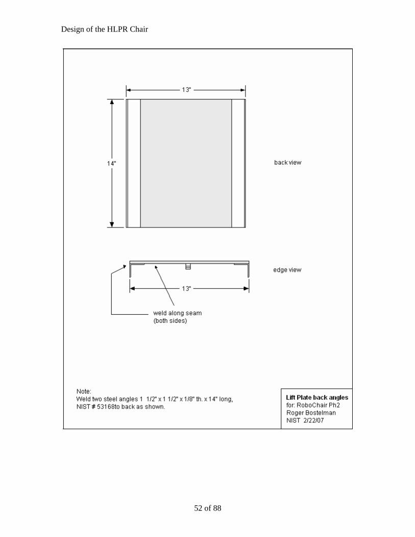
Modifications to Original Designs
51 of 88
Design of the HLPR Chair
52 of 88

Design of the HLPR Chair
53 of 88

Design of the HLPR Chair
54 of 88

Design of the HLPR Chair
55 of 88
Design of the HLPR Chair
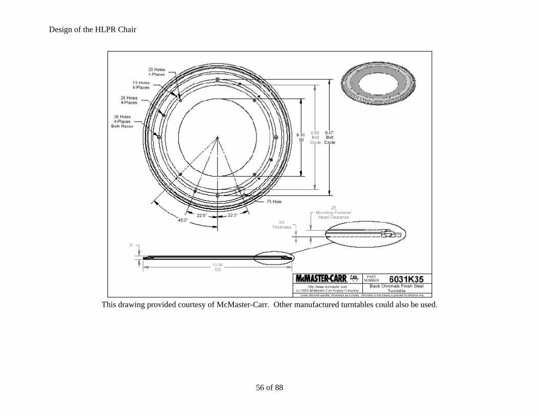
This drawing provided courtesy of McMaster-Carr. Other manufactured turntables could also be used.
56 of 88

Design of the HLPR Chair
57 of 88

Design of the HLPR Chair
58 of 88
Design of the HLPR Chair
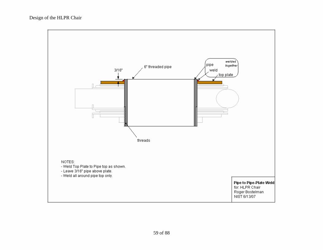
59 of 88

Design of the HLPR Chair
60 of 88

ir
61 of 88
Design of the HLPR Cha

Design of the HLPR Chair
62 of 88
Design of the HLPR Chair
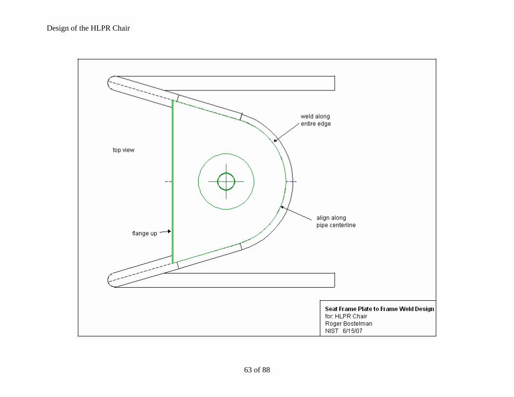
63 of 88

ir
64 of 88
Design of the HLPR Cha

Design of the HLPR Chair
65 of 88
Design of the HLPR Chair
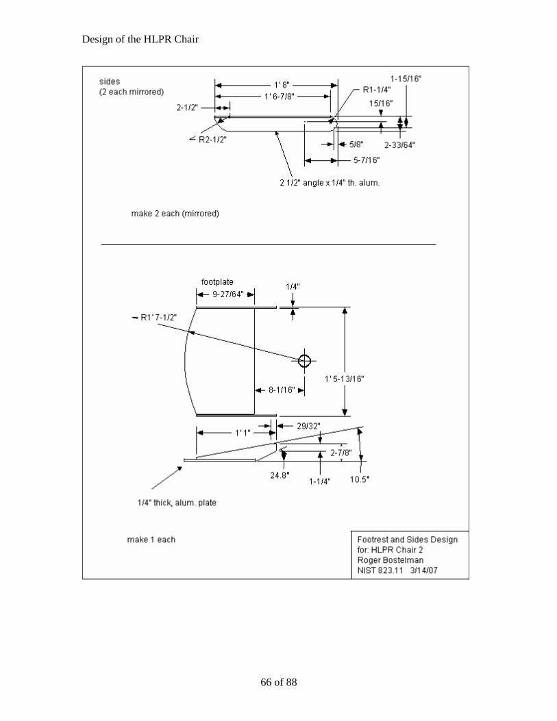
66 of 88

Design of the HLPR Chair
67 of 88

Design of the HLPR Chair
68 of 88

Design of the HLPR Chair
69 of 88
Design of the HLPR Chair
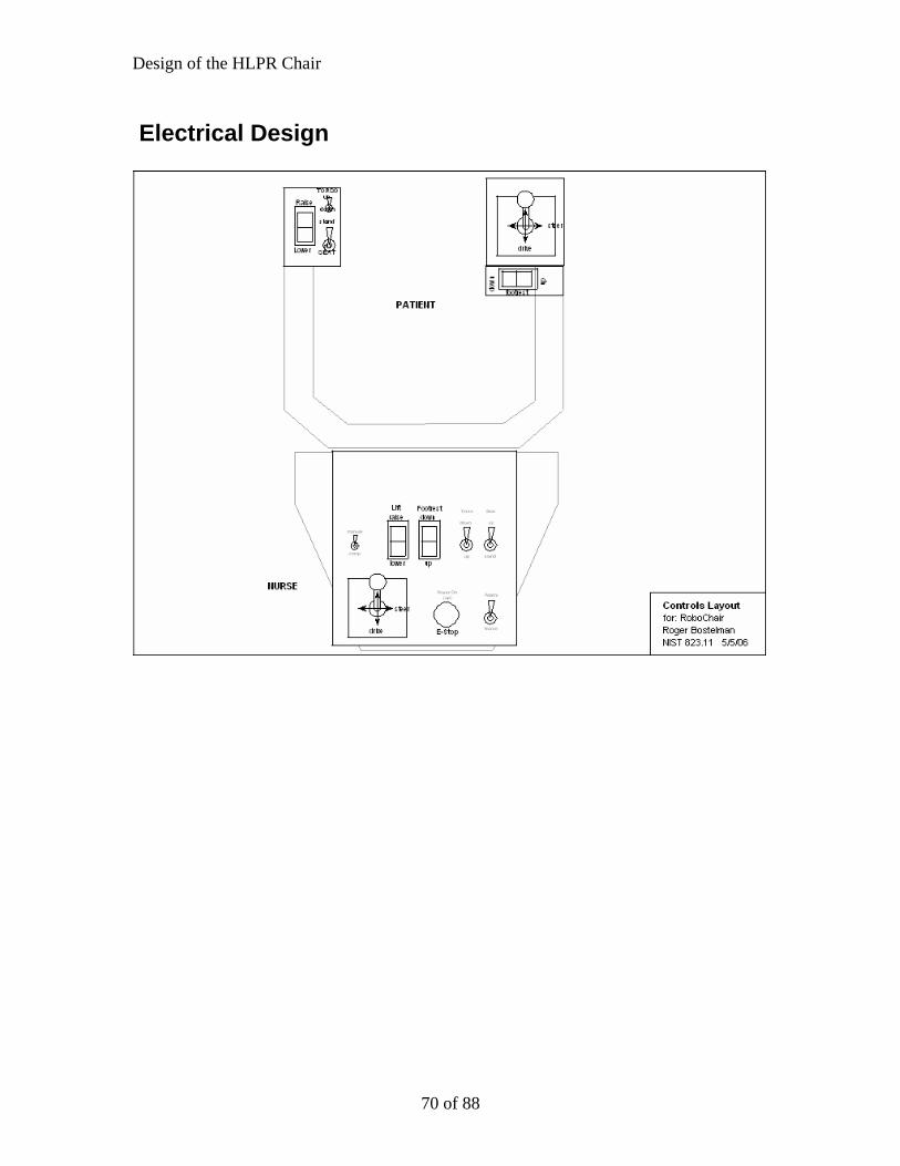
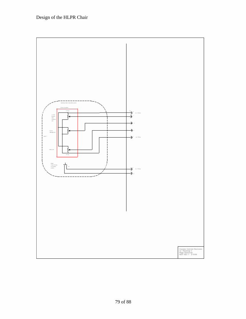
Electrical Design
70 of 88
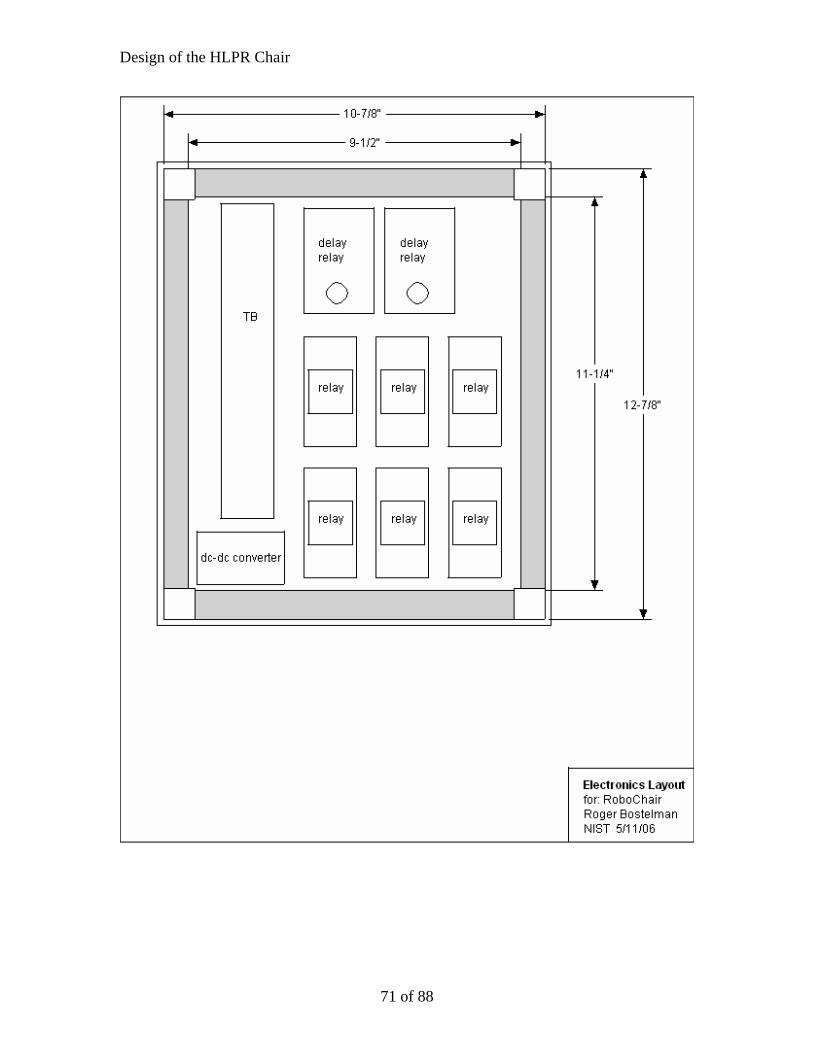
Design of the HLPR Chair
71 of 88
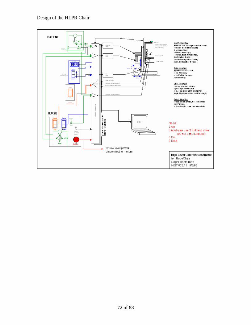
Design of the HLPR Chair
72 of 88

Design of the HLPR Chair
73 of 88
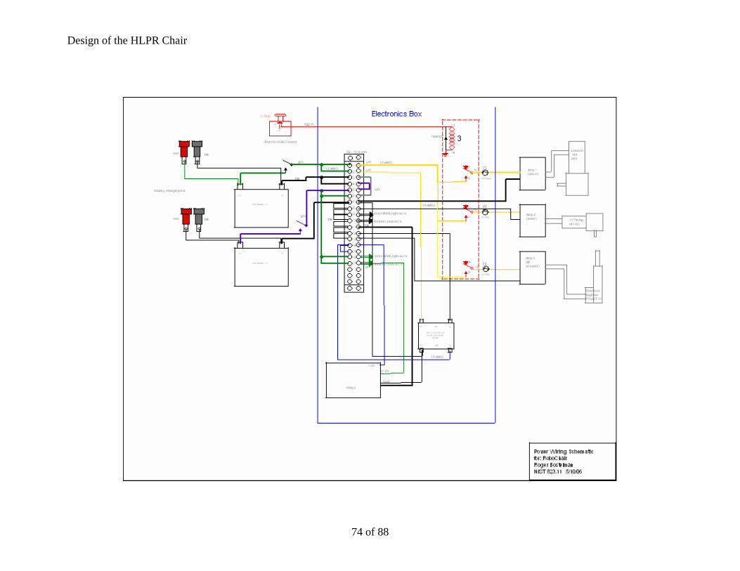
Design of the HLPR Chair
74 of 88
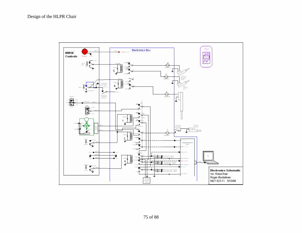
Design of the HLPR Chair
75 of 88
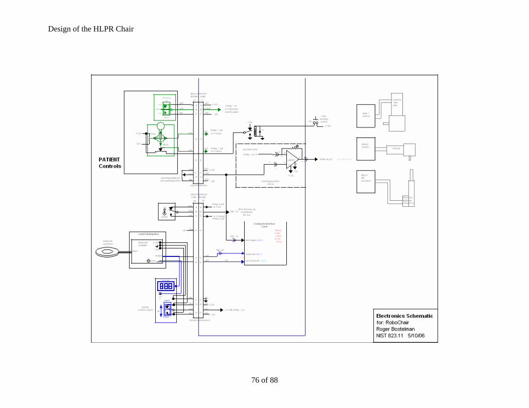
Design of the HLPR Chair
76 of 88

ir
77 of 88
Design of the HLPR Cha

Design of the HLPR Chair
78 of 88
Design of the HLPR Chair
79 of 88

Design of the HLPR Chair
80 of 88
Design of the HLPR Chair
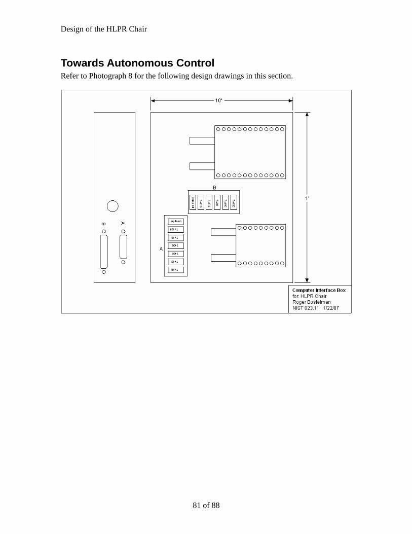
Towards Autonomous Control Refer to Photograph 8 for the following design drawings in this section.
81 of 88

Design of the HLPR Chair
82 of 88

Design of the HLPR Chair
83 of 88

Design of the HLPR Chair
84 of 88
Design of the HLPR Chair
85 of 88

Design of the HLPR Chair
86 of 88

Design of the HLPR Chair
Stability Testing
87 of 88
Design of the HLPR Chair
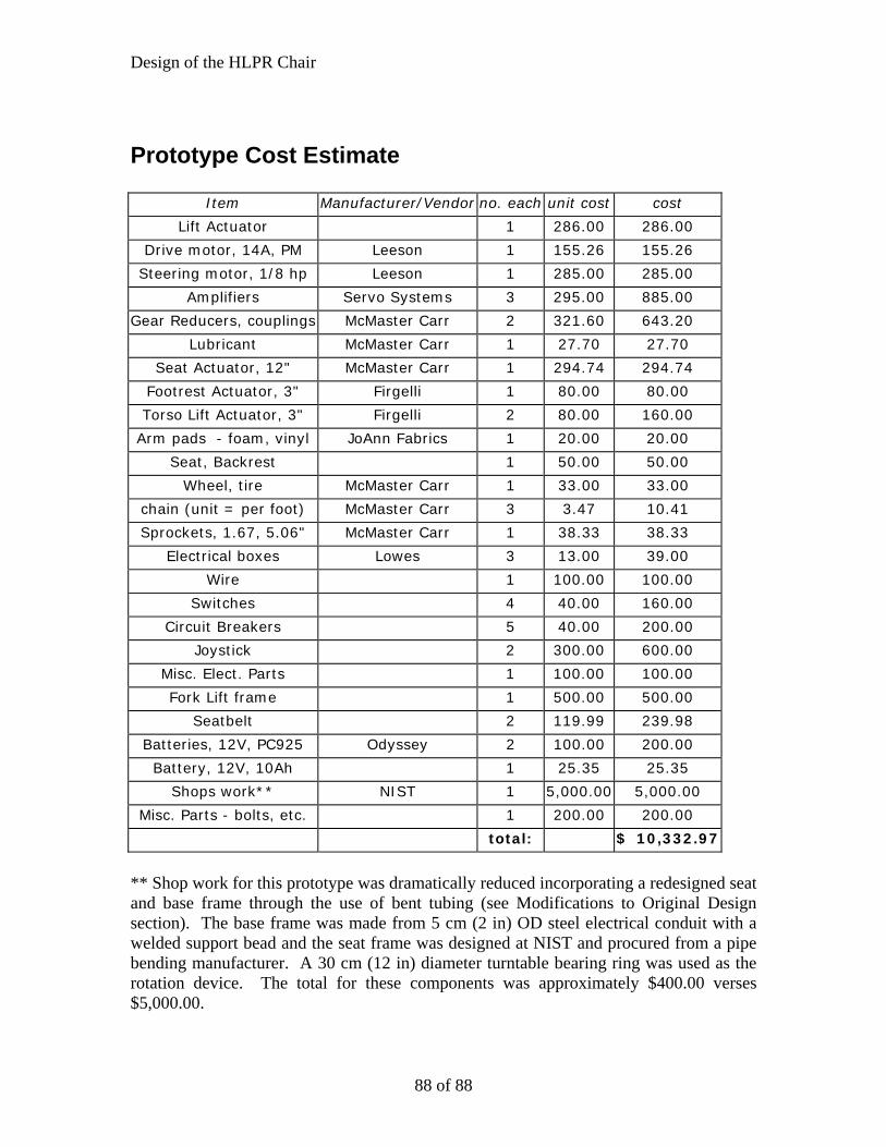
Prototype Cost Estimate
Item Manufacturer/Vendor no. each unit cost cost
Lift Actuator 1 286.00 286.00
Drive motor, 14A, PM Leeson 1 155.26 155.26
Steering motor, 1/8 hp Leeson 1 285.00 285.00
Amplifiers Servo Systems 3 295.00 885.00
Gear Reducers, couplings McMaster Carr 2 321.60 643.20
Lubricant McMaster Carr 1 27.70 27.70
Seat Actuator, 12" McMaster Carr 1 294.74 294.74
Footrest Actuator, 3" Firgelli 1 80.00 80.00
Torso Lift Actuator, 3" Firgelli 2 80.00 160.00
Arm pads - foam, vinyl JoAnn Fabrics 1 20.00 20.00
Seat, Backrest 1 50.00 50.00
Wheel, tire McMaster Carr 1 33.00 33.00
chain (unit = per foot) McMaster Carr 3 3.47 10.41
Sprockets, 1.67, 5.06" McMaster Carr 1 38.33 38.33
Electrical boxes Lowes 3 13.00 39.00
Wire 1 100.00 100.00
Switches 4 40.00 160.00
Circuit Breakers 5 40.00 200.00
Joystick 2 300.00 600.00
Misc. Elect. Parts 1 100.00 100.00
Fork Lift frame 1 500.00 500.00
Seatbelt 2 119.99 239.98
Batteries, 12V, PC925 Odyssey 2 100.00 200.00
Battery, 12V, 10Ah 1 25.35 25.35
Shops work** NIST 1 5,000.00 5,000.00
Misc. Parts - bolts, etc. 1 200.00 200.00
total: $ 10,332.97
** Shop work for this prototype was dramatically reduced incorporating a redesigned seat and base frame through the use of bent tubing (see Modifications to Original Design section). The base frame was made from 5 cm (2 in) OD steel electrical conduit with a welded support bead and the seat frame was designed at NIST and procured from a pipe bending manufacturer. A 30 cm (12 in) diameter turntable bearing ring was used as the rotation device. The total for these components was approximately $400.00 verses $5,000.00.
88 of 88
Related Documents