Al-Mustansiriyah University College of Engineering Highway & Transportation Department 4 th Year Stage/ Lecture Notes Subject Code: 506064052 Design of Steel Bridges Structures Asst. Prof. Awadh E. Ajeel Shear Connectors Diaphragm Lateral Bracing Stiffeners Connection Splice Girders Reinforcing for CIP Deck Slab Ǧ Ȁ

Welcome message from author
This document is posted to help you gain knowledge. Please leave a comment to let me know what you think about it! Share it to your friends and learn new things together.
Transcript

Al-Mustansiriyah University College of Engineering Highway & Transportation Department 4th Year Stage/ Lecture Notes Subject Code: 506064052
Design of Steel Bridges Structures Asst. Prof. Awadh E. Ajeel
Shear Connectors
Diaphragm
Lateral Bracing
Stiffeners
Connection
Splice
GirdersReinforcing for CIP Deck Slab

Asst. Prof. Awadh E. Ajeel 506064052: Design of Steel Bridges Structures Superstructures Forms of Steel Bridges
1
1. Superstructures Forms of Steel Bridges
1.1. Slab-Steel Beam Bridges The common forms of steel bridges, utilized for short- and medium-span highway structures and
variously referred to as slab-steel beam, slab-stringer and slab-steel girder. Structurally, they consist of rolled steel beams (W-shapes) parallel to traffic with usually equally spaced transversely to support a reinforced concrete deck (Figure 1.1). For longer spans in the 100 - 200 ft range, plate girders are used. Plate girders are simply built-up steel beams fabricated from two flange plates and a web plate, the webs being deeper than those available with the deepest rolled beams. Steel plate girder bridges are particularly suitable for bridges curved in plan.
1.2. Orthotropic Steel Bridges These forms are characterized by stiffened steel plate decks supported on longitudinal girders (I-
beams or box beams), thus called orthotropic bridges or orthotropic steel deck bridges (Figure 1.2). Orthotropic bridges are lightweight, very economical and possessed excellent structural characteristics. These bridge types evolved in Europe primarily Germany the longest structure of this type in the world has 5542 ft spans and built to across San Francisco Bay, California.
1.3. Composite Steel Box Girder Bridges Composite steel box girder bridges are suitable for single spans longer than 75 ft and for continuous
spans longer than 120 ft. These are tubular bridge superstructures in which the bottom flange and the web are fabricated from steel plate while the deck is made from reinforced concrete, hence they are termed as composite. A box girder may be a single-cell, twin-cell or multiple-cell (multicellular) structure (Figure 1.3). Alternatively, a steel box girder may have two or more separate closed cross sections with reinforced concrete deck also known as multispine bridge. The webs of box girders may be vertical or inclined; the latter gives the advantage of narrower bottom flange. The top flange widths are usually wider enough to provide the required bearing surface for the concrete deck supported on them as well as for placement of shear connectors necessary to develop composite action.
Because of their closed cross sections, box girder bridges possess high strength and torsional rigidity in comparison with an equal number of open cross sections such as rolled beams or plate girders. Their high torsional strength makes them the most suitable for curved bridges that are inherently subjected to torsional moments. Also, they are preferred for grade separation structures in urban areas. From architectural wise, the inclined webs of a box girder give the bridge an aesthetically pleasing appearance.
1.4. Delta Frame Steel Bridges Delta frame bridges are essentially rigid frame structures that consist of superstructures supported
on vertical or inclined monolithic legs (columns) as shown in Figure 1.4. They are considered economically suitable for medium-span lengths. For analytical purposes, delta frame bridges may be treated similar to two-hinged or fixed arches. The only difference is that instead of generally accepted form of continuous smooth curve of an arch axis, a rigid frame bridge with inclined legs has an arch axis that is trapezoidal in form and a rigid frame bridge with vertical legs has a rectangular form.

Asst. Prof. Awadh E. Ajeel 506064052: Design of Steel Bridges Structures Superstructures Forms of Steel Bridges
2
Figure 1.1: Slab-Steel Beam Bridges
Figure 1.2: Orthotropic Steel Bridges
Figure 1.3: Composite Steel Box Girder Bridges
Figure 1.4: Delta Frame Steel Bridges

Asst. Prof. Awadh E. Ajeel 506064052: Design of Steel Bridges Structures General Considerations for Steel Bridges
3
2. General Considerations for Steel Bridges
2.1. Corrosion Considerations The corrosion problem is particularly acute when the steel bridge is not protected or maintained
properly. The accumulation of salt and water is considered the primary cause of corrosion in highway steel bridges. So, corrosion-resistant steel may be used to mitigate the corrosion problem. There are five main forms of corrosion are identified in steel bridge:
General Corrosion The common form of corrosion, refers to the general loss of surface material over time, leading to
gradual thinning of members. Because this corrosion type can be extreme resulting in the loss of cross-sectional area of the members, the load-carrying capacity is threatened to be lost (Figure 2.1).
Pitting Corrosion This corrosion type of also causes loss of material, although it is localized and restricted to small
areas. Pits can be characterized as rolled-in imperfections that can be dangerous, for they inconspicuously extend into the metal. Their presence in high-stress regions becomes a source of stress concentration.
Galvanic Corrosion This corrosion occurs when two dissimilar metals are electrochemically coupled. For example, in
welded or bolted connections, the bolt metal is different from the weld metal. The iron oxide forms on structural steel after hot rolling can galvanically encourage corrosion of the underlying base metal.
Crevice Corrosion Refers to corrosion that occurs in small confined areas such as peeling paint between faying
surfaces or at pit locations.
Stress Corrosion Refers to tensile loading of metal in a corrosive environment. An existing crack on a metal’s surface
spreads gradually under repetitive loading (fatigue). However, formation of rust at the crack tip accelerates this spreading of the crack.
Figure 2.1: Corrosion of Structural Steel in Bridges
Asst. Prof. Awadh E. Ajeel 506064052: Design of Steel Bridges Structures General Considerations for Steel Bridges
4
2.2. Construction Considerations Bridges should be designed in a manner guarantees that fabrication and erection can be performed
without probability of failure or deformed in degree out of the acceptable levels of deflection, strength of materials and stability during construction.
Shored Construction In beam-type of steel bridges, the beams are installed between the end supports and supported at
intermediate points by temporary shores placed at close intervals. The temporary shores keep these beams in almost undeformed condition during construction and hardening period of fresh concrete poured to produce the deck slab. While shored construction is permitted according to LRFD Specifications, its use is not recommended due to further costs.
Unshored Construction In this way of construction, the beams are installed between the end supports, and concrete is
poured. Until the concrete hardens, the loads due to dead weight of the beams and concrete are resisted by the steel section alone. Permanent loads and live load applied after hardening of concrete are assumed to be resisted by the composite section of the deck slab and supporting beams.
2.3. Mechanical Properties of Steel for Highway Bridges The following design properties shall be used for all grades of structural steel used in design of:
Modulus of Elasticity x ksi
Coefficient of Thermal Expansion x °
Tensile Strength Specified yield strength ( ) also called as steel grade and the specified minimum ultimate or
tensile strength ( ) are tubulated below.
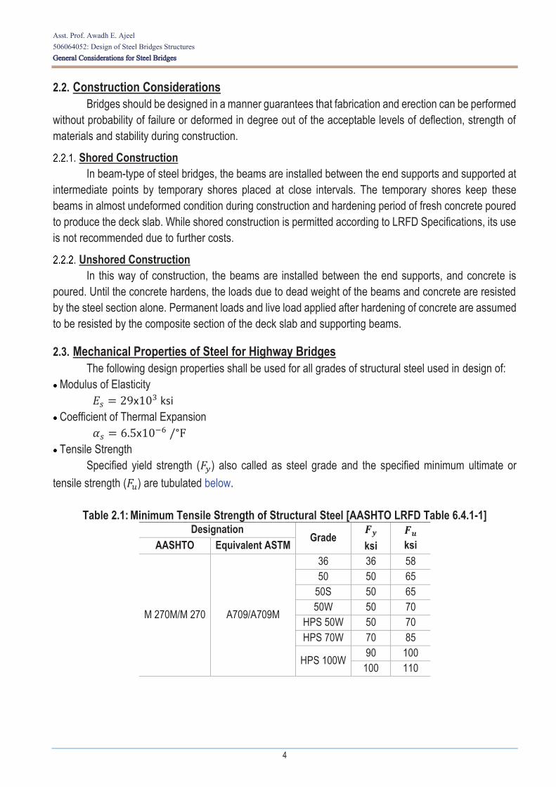
Table 2.1: Minimum Tensile Strength of Structural Steel [AASHTO LRFD Table 6.4.1-1] Designation
Grade
ksi
ksi AASHTO Equivalent ASTM
M 270M/M 270 A709/A709M
36 36 58 50 50 65
50S 50 65 50W 50 70
HPS 50W 50 70 HPS 70W 70 85
HPS 100W 90 100 100 110
Asst. Prof. Awadh E. Ajeel 506064052: Design of Steel Bridges Structures General Considerations for Steel Bridges
5
2.4. Noncomposite and Composite Sections The basic layout for a slab-steel girder bridge consists of a concrete deck slab supported over steel
beams. From the manner of how the basic steel girder is connected to its supported concrete deck slab, the entire section act as composite or noncomposite.
Noncomposite Sections When the deck is not physically connected to the girders by shear connectors, the deck merely sits
on girders and transfers loads by bearing on them. In this case, steel girders are alone designed to carry the entire gravity load on the bridge and referred to as noncomposite sections. Noncomposite sections are not recommended because they demand larger sections and they are relatively uneconomical.
Composite Sections When the top flanges of steel girders are provided with welded shear connectors that embedded
in the bottom of the concrete deck during pouring. The dead load of the deck is resisted by the steel girders alone by bearing. After the concrete hardens, subsequent loads (superimposed dead load and the live load) on the superstructure are resisted by the girders and the deck acting as a unit. In such case, girder sections are designed and referred to as composite section.
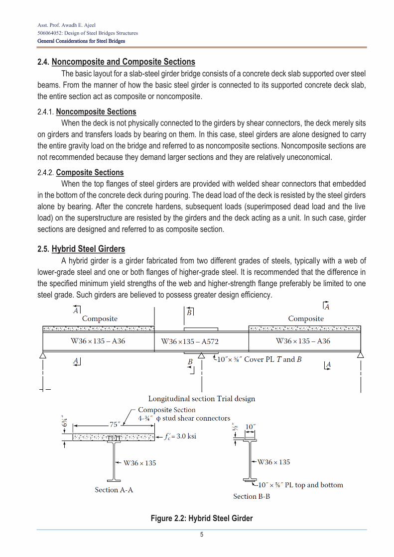
2.5. Hybrid Steel Girders A hybrid girder is a girder fabricated from two different grades of steels, typically with a web of
lower-grade steel and one or both flanges of higher-grade steel. It is recommended that the difference in the specified minimum yield strengths of the web and higher-strength flange preferably be limited to one steel grade. Such girders are believed to possess greater design efficiency.
Figure 2.2: Hybrid Steel Girder
Related Documents