- Design of Solid Slabs - Prepared by Edited by : Ir. Dr. Zainorizuan Mohd Jaini : Dr Nurazuwa Md Noor Faculty of Civil Engineering and Built Environment Universiti Tun Hussein Onn Malaysia

Welcome message from author
This document is posted to help you gain knowledge. Please leave a comment to let me know what you think about it! Share it to your friends and learn new things together.
Transcript

-Design of Solid Slabs
-
Prepared by
Edited by
: Ir. Dr. Zainorizuan Mohd Jaini
: Dr Nurazuwa Md Noor
Faculty of Civil Engineering and Built Environment
Universiti Tun Hussein Onn Malaysia

INTRODUCTION

Introduction
Slabs are plate elements forming floors and roofs in buildings
which normally carry uniformly distributed loads.
Slabs may be simply supported or continuous over one or
more supports and are classified according to the method of
support as follows:
– Spanning one way between beams or walls
– Spanning two ways between the support beams or walls
– Flat slabs carried on columns and edge beams or walls
with no interior beams
Slabs may be solid of uniform thickness or ribbed with ribs
running in one or two directions. Slabs with varying depth are
generally not used.
Type of slabs: One/two-way solid slabs, ribbed slabs, waffle
slabs, flat slab with/without drop panel.

Introduction
One way slab with band beam
Solid slab One way ribbed slab
Flat slab w/o drop panel Waffle slab
Flat slab w drop panel
Precast concrete slab

Introduction
One-way solid slab: Slabs of uniform thickness bending andreinforced in one direction. Suitable only for relatively shortspans.
Two-way solid slab: Slabs of uniform thickness bending andreinforced in two directions. Economical for medium spanswith intermediate to heavy loads.
Ribbed slabs: Slab cast integrally with a series of closelyspaced joist which in turn are supported by a set of beams.Designed as a series of parallel T-beams and economical formedium spans with light to medium live loads.
Waffle slabs: A two-way slab reinforced by ribs in two-dimensions. Able to carry heavier loads and span longer thanribbed slabs.
Flab slabs: Slabs of uniform thickness bending and reinforcedin two directions and supported directly by columns withoutbeams.

DESIGN PROCEDURE

Procedure of Design
Slabs are plate elements forming floors and roofs in buildings
which normally carry uniformly distributed loads.
Slabs may be simply supported or continuous over one or
more supports and are classified according to the method of
support as follows:
– Spanning one way between beams or walls
– Spanning two ways between the support beams or walls
– Flat slabs carried on columns and edge beams or walls
with no interior beams
Slabs may be solid of uniform thickness or ribbed with ribs
running in one or two directions. Slabs with varying depth are
generally not used.
Type of slabs: One/two-way solid slabs, ribbed slabs, waffle
slabs, flat slab with/without drop panel.
Step Task Standard
1 Determine design life, exposure class and
fire resistance
EN 1990 Table 2.1
EN 1992-1-1: Table 4.1
EN 1992-1-2: Sec.5.6
2 Determine material strength BS 8500-1: Table A.3
EN 206-1: Table F1
3 EN 1992-1-1: Table 7.4N
EN 1992-1-2: Table 5.8
4 Calculate nominal cover, Cnom EN 1992-1-1: Sec.4.4.1
5 Design actions, NEd EN 1991-1-1
6 EN 1992-1-1: Sec.5
7 EN 1992-1-1: Sec.6.1
8 EN 1992-1-1: Sec.6.2
9 EN 1992-1-1: Sec.7.4
10 EN 1992-1-1: Sec.9.3
11 Detailing EN 1992-1-1: Sec.8 & 9.3

SLAB THICKNESS

Thickness of Slab
The selection of slab thickness from structural viewpoint is
often dictated by deflection control criteria.
In practice, the overall depths of slabs are often fixed in
relation to their spans.
Span to overall depth ratios of 20 to 30 are generally found to
be economical in the case of simply supported and
continuous slabs.
Estimated for deflection control:
h L
h L
20 30
This is based on the ratio of span/effective depth as in Table
7.4N BS EN 1992-1-1:2004.
The minimum thickness for fire resistance is stated in Table
5.8 BS EN 1992-1-2.
Thickness of Slab
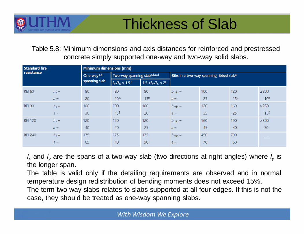
Table 5.8: Minimum dimensions and axis distances for reinforced and prestressed
concrete simply supported one-way and two-way solid slabs.
lx and ly are the spans of a two-way slab (two directions at right angles) where ly is
the longer span.
The table is valid only if the detailing requirements are observed and in normal
temperature design redistribution of bending moments does not exceed 15%.
The term two way slabs relates to slabs supported at all four edges. If this is not the
case, they should be treated as one-way spanning slabs.

LOADING ANALYSIS

Moment and Shear Force
Slab may be analyzed using the following methods:
1) Elastic analysis covers three techniques:
(a) idealization into one-way/two-way spanning
(b) elastic plate analysis
(c) finite element analysis
2) For the method of design coefficients use is made of the
moment and shear coefficients given in the code, which
have been obtained from yield line analysis.
For slab, the analysis of moment and shear force may based
on BS8110 for the following cases:
- One-way simply supported/constrained slab
- One-way continuous slab
- Two-way simply supported slab
- Two-way constrained slab

Moment and Shear Force
Simply supported/Contraint one-way slab
Similar to simply supported beam, for 1m slab width:
One-way continuous slab
Moment and shear force can be obtained from Table 3.12,
BS8110:
2
max
d
8
n LMoment, M max
d
2
n L; Shear, V
End support condition
Pinned Continuous
Outer
support
Near
middle of
end span
End support End span At 1st
interior
support
At middle
of interior
span
At interior
support
Moment 0 0.086FL 0.075FL 0.086FL 0.063FL 0.063FL
Shear 0.4F 0.46F 0.6FL 0.5FL
L = effective span *The use of this table must follow the applied conditions
F = total ultimate load = 1.35Gk + 1.5Qk

Moment and Shear Force
Table 3.12 only can be used of the slab fullfill the following
requirement:
• The area of each bay, i.e. the building width × column
spacing, exceeds 30 m2.
• The ratio of characteristic imposed load to characteristic
dead load does not exceed 1.25.
• The characteristic imposed load does not exceed 5 kN/m2
excluding partitions.
If the above conditions are
not satisfied, the slab can
be analyzed using elastic
analysis as performed for
continuous beams.
Moment and Shear Force
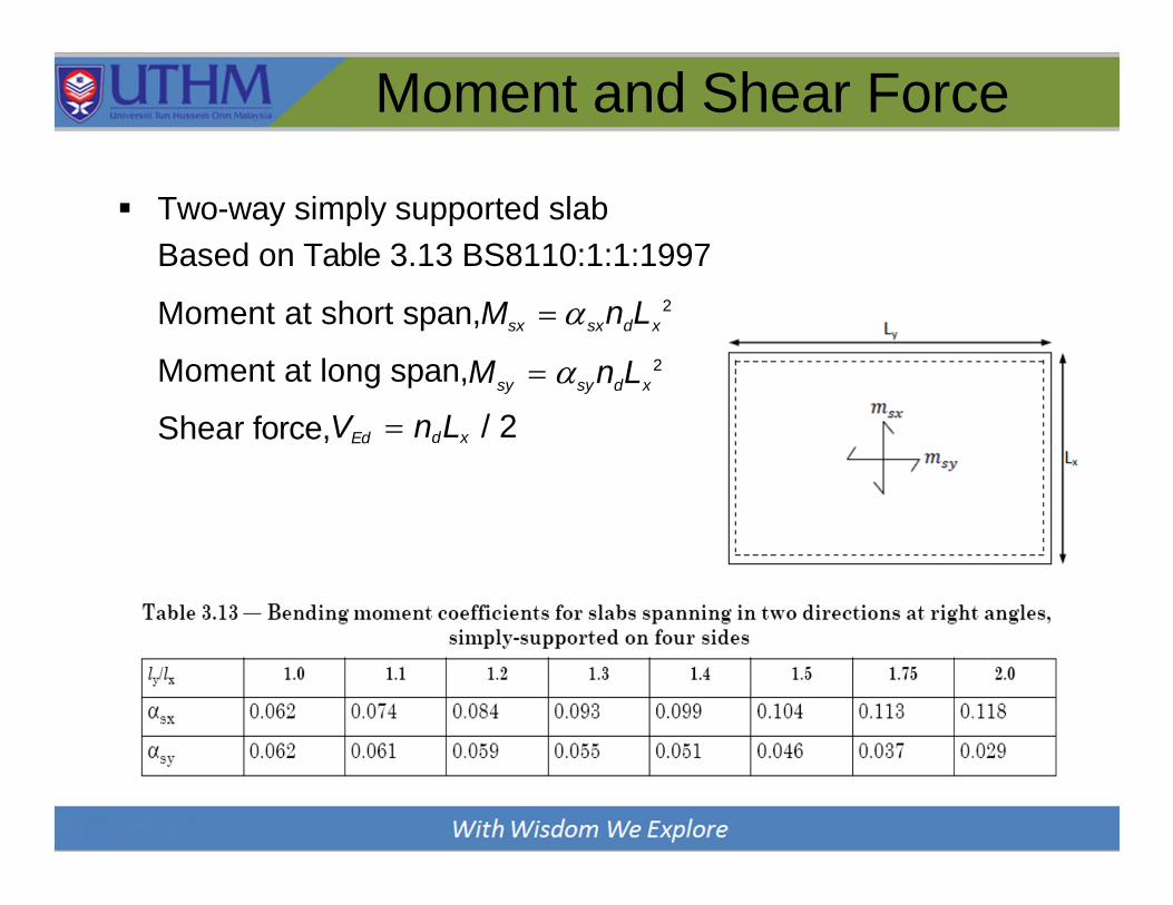
Two-way simply supported slab
Based on Table 3.13 BS8110:1:1:1997
2
sx sx d xMoment at short span,M n L
2
sy sy d xMoment at long span,M n L
Shear force,VEd ndLx / 2

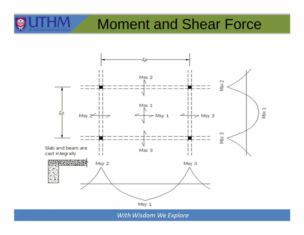
Moment and Shear Force
Two-way constrained slab
Based on Table 3.14 and Table 3.15 BS8110:1:1:1997
2
sx sx d xMoment at short span,M n L
2
syMoment at long span,M n L
Shear force at short span,Vsx
sy d x
vxndLx
Shear force at long span,Vsy vyndLx
Moment and Shear Force
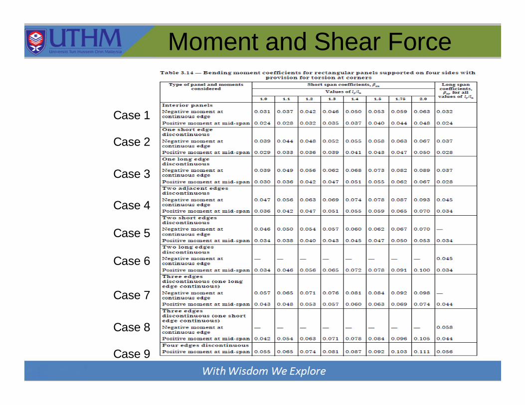
Moment and Shear Force
Case 1
Case 2
Case 3
Case 4
Case 5
Case 6
Case 7
Case 8
Case 9

Moment and Shear Force
Case 1
Case 2
Case 3
Case 4
Case 5
Case 6
Case 7
Case 8
Case 9

DESIGN
OF FLEXURAL
REINFORCEMENT
Flexural Reinforcement
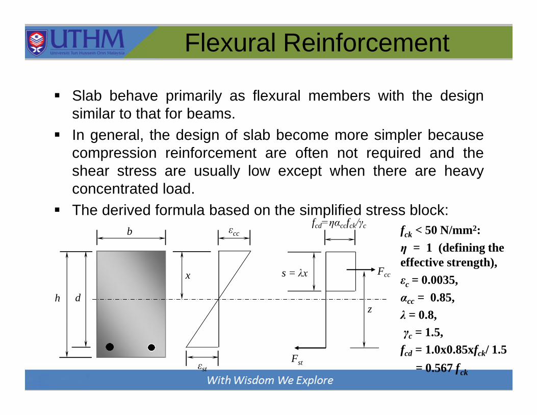
Slab behave primarily as flexural members with the design
similar to that for beams.
In general, the design of slab become more simpler because
compression reinforcement are often not required and the
shear stress are usually low except when there are heavy
concentrated load.
The derived formula based on the simplified stress block:
dh
b
x
εcc
εstFst
fcd=ηαccfck/γc
Fcc
z
s = λx
ckf < 50 N/mm2:
η = 1 (defining the
effective strength),
ε = 0.0035,c
αcc = 0.85,
λ = 0.8,
γc = 1.5,
fcd = 1.0x0.85xfck/ 1.5
= 0.567 fck

Flexural Reinforcement
Follow a similar procedure to that use in beam design:
1) Calculate
2) If K ≤ Kbal=0.167, compression reinforcement is not
required, hence
ck
MEdK bd 2f
z d 0.5 0.25 K / 1.134 0.95d
s
yk
3) Minimum and maximum reinforcement
MA
0.87f z
0.26 fctm / fyk bd 0.0013bd
0.04Ac 0.04bh
As,min
As,max
Flexural Reinforcement
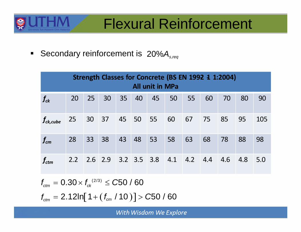
Secondary reinforcement is 20%As,req
Strength Classes for Concrete (BS EN 1992‐ 1‐ 1:2004) All unit in MPa
fck 20 25 30 35 40 45 50 55 60 70 80 90
fck,cube 25 30 37 45 50 55 60 67 75 85 95 105
fcm 28 33 38 43 48 53 58 63 68 78 88 98
fctm 2.2 2.6 2.9 3.2 3.5 3.8 4.1 4.2 4.4 4.6 4.8 5.0
(2/3)
ctm ckf 0.30 f C50 / 60
fctm 2.12ln1 fcm / 10 C50 / 60

DESIGN OF SHEAR
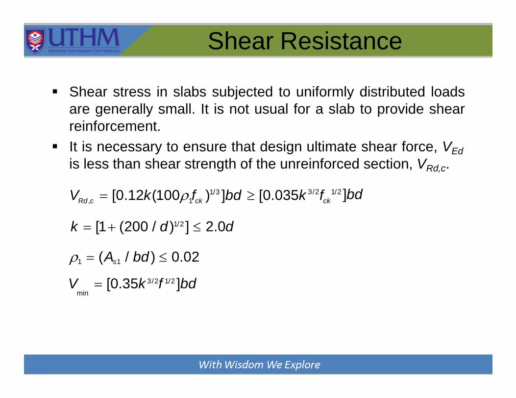
Shear Resistance
Shear stress in slabs subjected to uniformly distributed loads
are generally small. It is not usual for a slab to provide shear
reinforcement.
It is necessary to ensure that design ultimate shear force, VEd
is less than shear strength of the unreinforced section, VRd,c.
1/3
Rd ,c 1 ck ckV [0.12k(100 f ) ]bd [0.035k f3/2 1/2 ]bd
k [1 (200 / d )1/2 ] 2.0d
1 (As1 / bd ) 0.02
V [0.35k 3/2f 1/2 ]bdmin

DEFLECTION

Deflection Control
Excessive deflection of slabs will cause damage to the ceiling,
floor finishes or other architectural finishes.
To avoid this, limit are set on the span-depth ratio. These limit
are similarly to limit for beams.
As a slab is usually a slender member, the restrictions on the
span-depth ratio become more important and this can often
control the depth of slab required.
Two equations are provided in Eq. 7.16.a and 7.16.b,
Cl 7.4.2.(2):
3/2
0
0
01 if ck ck
K 11 1.5 f 3.2 fl
d
,
0
if 0
0 1
, 12
l
K 11 1.5 fck fckd

Deflection Control
Percentage of required tension reinforcement
Reference reinforcement ratio
Percentage of required compression reinforcement
Factor for structural system, K must be referred in Table 7.4N
Modification factor:
- Span greater than 7m = 7/L
< 1.5
span/500 or 20mm after
- Steel area provided = As,prov/As,req
Deflection limited to span/250,
installation.
As,req / bd
,
s ',req A / bd
1/2
0 ck (f ) 103

Deflection Control
effallow actual
l l leff l MF d d i d d
Table 7.4N: Basic ratio of span/effective depth for reinforced concrete
members without axial compression

CRACKING
CONTROL
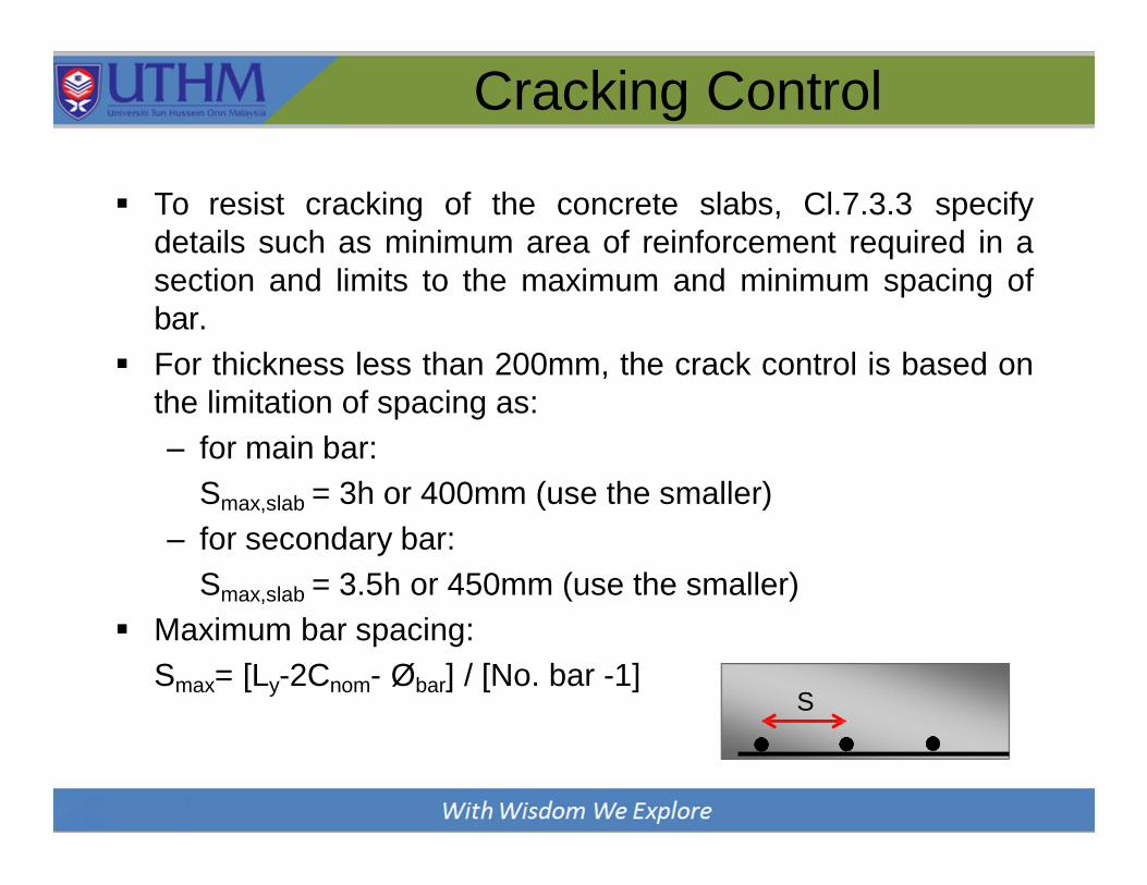
Cracking Control
To resist cracking of the concrete slabs, Cl.7.3.3 specify
details such as minimum area of reinforcement required in a
section and limits to the maximum and minimum spacing of
bar.
For thickness less than 200mm, the crack control is based on
the limitation of spacing as:
– for main bar:
Smax,slab = 3h or 400mm (use the smaller)
– for secondary bar:
Smax,slab = 3.5h or 450mm (use the smaller)
Maximum bar spacing:
Smax= [Ly-2Cnom- Øbar] / [No. bar -1]S

DETAILING

Detailing
Simplified rules for curtailment, Cl. 9.3
Continuous slab
Simply supported slab

EXAMPLE

Example
Refer to UTM Book
1. Example 7.1: Simply supported one‐way slab
2. Example 7.2: Continuous one‐way slab
3. Example 7.3: Simply supported two‐way slab
4. Example 7.4: Two‐way restrained slab
Related Documents


