CHAPTER 1 INTRODUCTION 1.0 HISTORY OF ASHOK LEYLAND Ashok Leyland is an Indian automobile manufacturing company based in Chennai , India. Founded in 1948, the company is one of India's leading manufacturers of commercial vehicles, such as trucks and buses, as well as emergency and military vehicles. Operating six plants, Ashok Leyland also makes spare parts and engines for industrial and marine applications. It sells about 60,000 vehicles and about 7,000 engines annually. It is the second largest commercial vehicle company in India in the medium and heavy commercial vehicle (M&HCV) segment with a market share of 28% (2007–08). With passenger transportation options ranging from 19 seaters to 80 seaters, Ashok Leyland is a market leader in the bus segment.The company claims to carry over 60 million passengers a day, more people than the entire Indian rail network. In the trucks segment Ashok Leyland primarily concentrates on the 16 ton to 25 ton range of trucks. However Ashok Leyland has presence in 1

Welcome message from author
This document is posted to help you gain knowledge. Please leave a comment to let me know what you think about it! Share it to your friends and learn new things together.
Transcript

CHAPTER 1
INTRODUCTION1.0 HISTORY OF ASHOK LEYLAND
Ashok Leyland is an Indian automobile manufacturing company based
in Chennai, India. Founded in 1948, the company is one of India's leading
manufacturers of commercial vehicles, such as trucks and buses, as well as
emergency and military vehicles. Operating six plants, Ashok Leyland also makes
spare parts and engines for industrial and marine applications. It sells about 60,000
vehicles and about 7,000 engines annually. It is the second largest commercial
vehicle company in India in the medium and heavy commercial vehicle (M&HCV)
segment with a market share of 28% (2007–08).
With passenger transportation options ranging from 19 seaters to 80 seaters,
Ashok Leyland is a market leader in the bus segment.The company claims to carry
over 60 million passengers a day, more people than the entire Indian rail network.
In the trucks segment Ashok Leyland primarily concentrates on the 16 ton to 25
ton range of trucks. However Ashok Leyland has presence in the entire truck range
starting from 7.5 tons to 49 tons. The joint venture announced with Nissan
Motors of Japan would improve its presence in the Light Commercial Vehicle
(LCV) segment (<7.5 tons).
Ashok Leyland's UK subsidiary Optare has shut down its bus factory in
Blackburn, Lancashire. This subsidiary's traditional home in Leeds has also been
vacated in favour of a purpose built plant at Sherburn in Elmet. Early products
included the Leyland Comet bus which was a passenger body built on a truck
chassis, sold in large numbers to many operators, including Hyderabad Road
Transport, Ahmedabad Municipality, Travancore State Transport, Maharashtra
State Transport and Delhi Road Transport Authority.
1

By 1963, the Comet was operated by every State Transport Undertaking in
India, and over 8,000 were in service. The Comet was soon joined in production by
a version of the Leyland Tiger.
In 1968, production of the Leyland Titan ceased in Britain, but was restarted
by Ashok Leyland in India. The Titan PD3 chassis was modified, and a five speed
heavy duty constant-mesh gearbox utilized, together with the Ashok Leyland
version of the O.680 engine. The Ashok Leyland Titan was very successful, and
continued in production for many years.
Over the years, Ashok Leyland vehicles have built a reputation for reliability
and ruggedness. This was mainly due to the product design legacy carried over
from British Leyland.
Ashok Leyland had a collaboration with the Japanese company Hino Motors
from whom the technology for the H-series engines was bought. Many indigenous
versions of H-series engine were developed with 4 and 6 cylinder and also
conforming to BS2 and BS3 emission norms in India. These engines proved to be
extremely popular with the customers primarily for their excellent fuel efficiency.
Most current models of Ashok Leyland come with H-series engines.
In the journey towards global standards of quality, Ashok Leyland reached a
major milestone in 1993 when it became the first in India's automobile history to
win the ISO 9002 certification. The more comprehensive ISO 9001 certification
came in 1994, QS 9000 in 1998 and ISO 14001 certification for all vehicle
manufacturing units in 2002. In 2006, Ashok Leyland became the first automobile
company in India to receive the TS16949 Corporate Certification. Editor’s note:
This is part of a series of articles peeking into clean car industries and car
manufacturers of China, India, South Korea and Germany.
Among many other goals, Ashok Leyland aims to expand its operations to
penetrate into overseas markets. Included in the company’s plans is to acquire 2

smaller car manufacturers in China and in other developing countries. In October
2006, Ashok Leyland bought a majority stake in the Czech based- Avia. Called
Avia Ashok Leyland Motors s.r.o., this will give Ashok Leyland a channel into the
competitive European market. According to the company, in 2008 the joint venture
sold 518 LCVs in Europe despite tough economic conditions. Furthermore, the
company will expand its product offers into construction equipment, following a
joint venture with John Deere. Newly formed in June 2009, the John Deere
partnership is a 50/50 split between the companies. The company says negotiation
is progressing on land acquisition, and the production plans are in place.
The venture is scheduled to start rolling out wheel loaders and backhoe
loaders in October 2010. Aside from the full expansion planned for the company,
Ashok Leyland is also paying close attention to the environment. In fact, they are
one of the companies showing the strongest commitment to environmental
protection, utilizing eco-friendly processes in their various plants. Even as they
thrust into different directions, Ashok Leyland maintains an R&D group that aims
to uncover ways to make their vehicles more fuel efficient and reduce emissions.
When it comes to the development of environmentally friendly technologies,
Ashok Leyland has developed Hythane engines. In association with the Australian
company Eden Energy, Ashok Leyland successfully developed a 6-cylinder, 6-liter
92 kW BS-4 engine which uses Hythane (H-CNG,) which is a blend of natural gas
and around 20% of hydrogen. Hydrogen helps improve the efficiency of the engine
but the CNG aspect makes sure that emissions are at a controlled level. A 4-
cylinder 4-litre 63 KW engine is also being developed for H-CNG blend in a joint
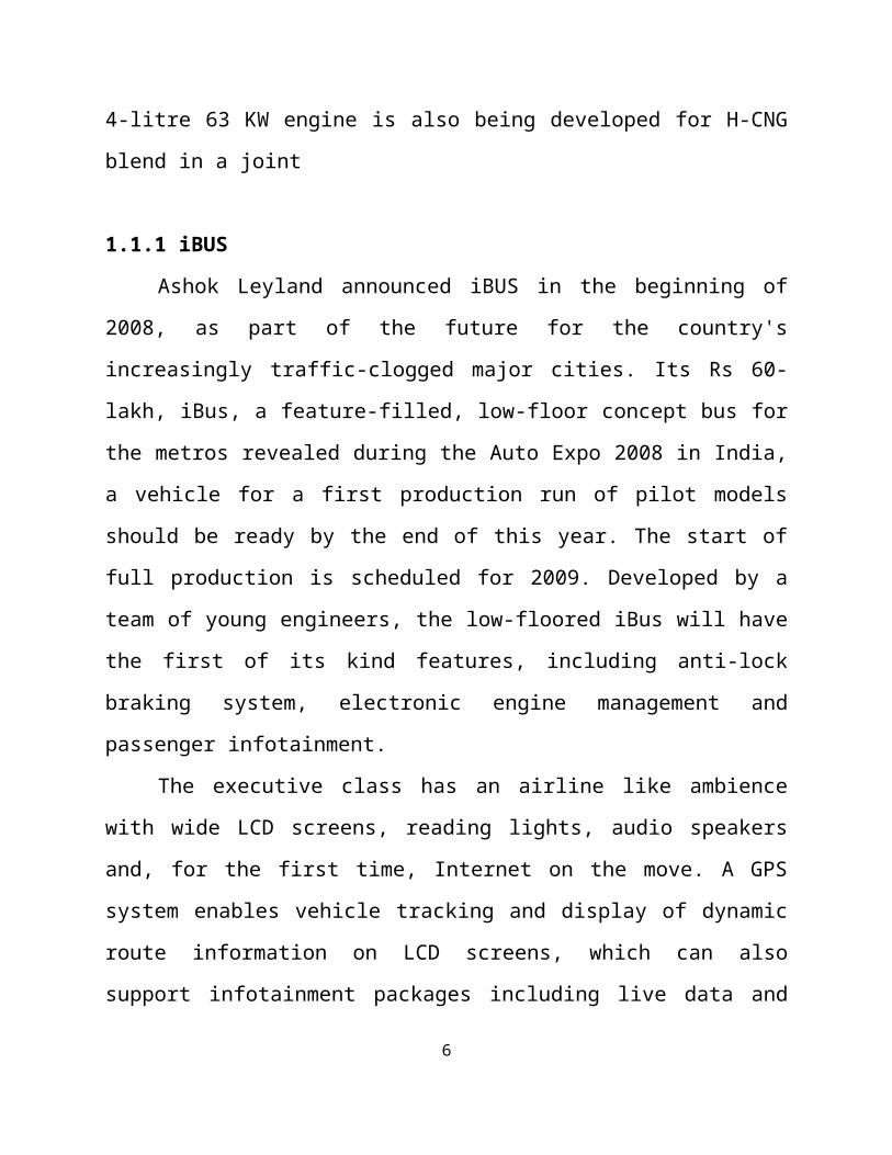
1.1.1 iBUS
Ashok Leyland announced iBUS in the beginning of 2008, as part of the
future for the country's increasingly traffic-clogged major cities. Its Rs 60-lakh, 3

iBus, a feature-filled, low-floor concept bus for the metros revealed during the
Auto Expo 2008 in India, a vehicle for a first production run of pilot models should
be ready by the end of this year. The start of full production is scheduled for 2009.
Developed by a team of young engineers, the low-floored iBus will have the first
of its kind features, including anti-lock braking system, electronic engine
management and passenger infotainment.
The executive class has an airline like ambience with wide LCD screens,
reading lights, audio speakers and, for the first time, Internet on the move. A GPS
system enables vehicle tracking and display of dynamic route information on LCD
screens, which can also support infotainment packages including live data and
news. The bus will probably be equipped with an engine from the new Neptune
family, which Ashok Leyland also introduced at this exhibition, which are ready
for the BS4/Euro 4 emission regulations and can be upgraded to Euro 5.
1.1.2 DOST
DOST is a 1.25 ton light commercial vehicle (LCV) that is the first product
to be launched by the Indian-Japanese commercial vehicle joint venture Ashok
Leyland Nissan Vehicles. Dost is powered by a 55 hp high-torque, 3-cylinder,
turbo-charged Common Rail Diesel engine and has a payload capacity of 1.25
Tonnes. It is available in both BS3 and BS4 versions. The LCV is being produced
in Ashok Leyland's plant in Tamil Nadu's Hosur.
4

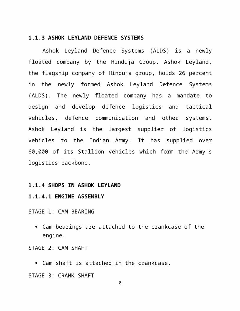
1.1.3 ASHOK LEYLAND DEFENCE SYSTEMS
Ashok Leyland Defence Systems (ALDS) is a newly floated company by the
Hinduja Group. Ashok Leyland, the flagship company of Hinduja group, holds 26
percent in the newly formed Ashok Leyland Defence Systems (ALDS). The newly
floated company has a mandate to design and develop defence logistics and tactical
vehicles, defence communication and other systems. Ashok Leyland is the largest
supplier of logistics vehicles to the Indian Army. It has supplied over 60,000 of its
Stallion vehicles which form the Army's logistics backbone.
1.1.4 SHOPS IN ASHOK LEYLAND
1.1.4.1 ENGINE ASSEMBLY
STAGE 1: CAM BEARING
Cam bearings are attached to the crankcase of the engine.
STAGE 2: CAM SHAFT
Cam shaft is attached in the crankcase.
STAGE 3: CRANK SHAFT
It is fixed at the base end of crankcase.
STAGE 4: STUDS
M14 studs are fixed to the holes of crankcase.
STAGE 5: TIMING BRAKE PLATE
It is fixed to the side of the engine.
5
STAGE 6: CAM GEAR
It is placed on the crankcase to operate cam shafts and to operate valves.
STAGE 7: FLYWHEEL
The flywheel is placed on housing; it also consists of seal housing and flange.
STAGE 8: OIL PUMP
It is fixed at top of crankcase. It is used to circulate oil to various parts of engine.
STAGE 9: PISTON
The piston is attached inside the bore of crankcase & it is connected to crankshaft. The oil ring and compression rings are also attached on the piston.
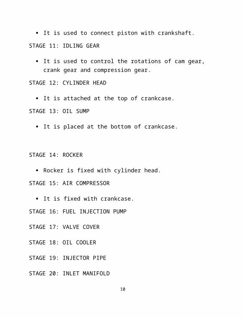
STAGE 10: CONROD BOLT
It is used to connect piston with crankshaft.
STAGE 11: IDLING GEAR
It is used to control the rotations of cam gear, crank gear and compression gear.
STAGE 12: CYLINDER HEAD
It is attached at the top of crankcase.
STAGE 13: OIL SUMP
It is placed at the bottom of crankcase.
6

STAGE 14: ROCKER
Rocker is fixed with cylinder head.
STAGE 15: AIR COMPRESSOR
It is fixed with crankcase.
STAGE 16: FUEL INJECTION PUMP
STAGE 17: VALVE COVER
STAGE 18: OIL COOLER
STAGE 19: INJECTOR PIPE
STAGE 20: INLET MANIFOLD
STAGE 20: SIDE COVER
STAGE 21: WATER PUMP
STAGE 22: STARTER MOTOR
STAGE 23: EXHAUST MANIFOLD
STAGE 24: TURBO CHARGER
STAGE 25: EII FITMENTS
STAGE 27: FULLY ASSSEMBLED
Finally, the assemble is taken to the testing section for checking the performance.
7
1.1.4.2 SHOP III
FRAME ASSEMBLY
There are several steps involved in frame assembly. They are as follows:
The side members and engine mounting are lifted using conveyor.
Assemble all cross members, steering mounting bracket, air cooler mounting bracket and rear spring brackets.
On rear end of the frame, both sides are aligned with taper pin.
Cross members are tightened well. Fit and tight FS and BKTS on both sides with dummy bolts.
Reaming process is done in the next step and the dummy bolts are removed.
Torque tightening in the rear brackets using M14 bolts on both sides.
Front and rear ends are fixed with four cab mountings.
Tighten the CB cross members using brake elbow adaptors.
Tilt the frame by 180o using tilting CUM lifting equipment.
Punch frame Sl. No. and spec on rear end of RH FSM.
Air blow the reamed burrs in assembled frame.
Lift and unload the assembled frame from conveyor on to trolley using tilting CUM lifting equipment.
Finally, the whole frame is carried to chassis assembly centre.
8

1.1.4.3 SHOP IV
The shop IV is classified into two departments. They are given below:
o Rear axle assembly.
o Front axle assembly.
REAR AXLE ASSEMBLY
The rear axle assembly consists of several stages. They are shown below:
Load rear axle casing on pedestals and remove wire strip, axle shafts.
Assemble dust covers on brake shoes and tighten with bolts and nuts.
Apply torque on mounting nuts.
Assemble inner ring for oil seal.
Distance piece is fixed to align the outer and inner wheel bearings in the same axis.
Fix the wheel drum.
Punch the Sl. No. on the rear axle.
Unload rear axle from conveyor and it is taken to the chassis assembly centre.
FRONT AXLE ASSEMBLY
The front axle assembly consists of several stages. They are discussed below:
First, the axle beam is loaded at conveyor belt.
The number is punched in the axle beam.
Next, the axle arm is fixed to beam of steering with pin fin and cotter pin using dummy bolts.
9
The tracking rod is fixed for the alignment of wheel. This will helps the left side of the tyre to turn along with the right side wheel.
Fix the air chamber and brake shoe.
Fix the hub and lock set using axle arm.
Fix the wheel drum to the both ends of axle arm.
Unload front axle from the conveyor and it is taken to the chassis assembly.
1.1.4.4 CHASSIS ASSEMBLY
The chassis assembly consists of 14 stages. They are discussed below:
In stage- 1, the front and rear axle is fixed on the main frame which is already fabricated from shop 3.
In stage- 2, the fr4ame assembly is placed on the conveyor belt, and then brake chamber is fitted into it.
In stage- 3, the steering gear box is fitted to the main frame.
In stage- 4, the propeller shaft is connected into the gear box flange. This propeller shaft is also coupled with universal joint.
In stage-5, the Vehicle Identification Number (VIN) is punched into the frame.
In stage- 6, the silencer tank is fixed into the main frame.
In stage- 7, the air tank and fuel tank is fixed at the rear end.
In stage- 8, the engine is mounted on the frame.
In stage- 9, the radiator is fixed at the front end of engine.
In stage- 10, the lever, fuel filter and accelerator assembly is linked with the engine.
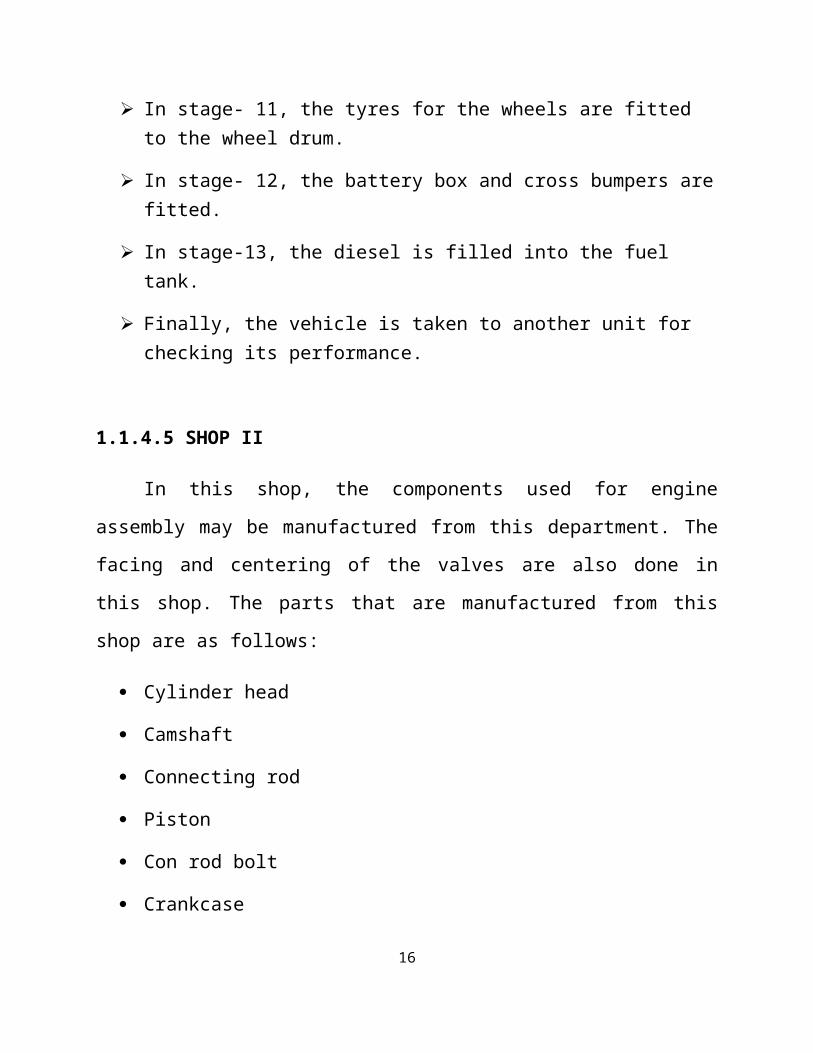
In stage- 11, the tyres for the wheels are fitted to the wheel drum.
10

In stage- 12, the battery box and cross bumpers are fitted.
In stage-13, the diesel is filled into the fuel tank.
Finally, the vehicle is taken to another unit for checking its performance.
1.1.4.5 SHOP II
In this shop, the components used for engine assembly may be manufactured
from this department. The facing and centering of the valves are also done in this
shop. The parts that are manufactured from this shop are as follows:
Cylinder head
Camshaft
Connecting rod
Piston
Con rod bolt
Crankcase
Spiral gear
Compound gear
For the preparation of con rod bolt, the workpiece is fitted in the multi spindle
lathe and the following processes will be done.
Head forming
Step turning
Chamfering
11

In the camshaft, the processes like taping, drilling, milling, grinding,
tempering, checking hardness are done in this shop II. The gear hobbing is also
done with the help of gear hobbing machine, after that the oil hole drilling may
proceeds. The journal bearing grindings and the cam grindings are done here. The
flywheel housing is tested and fitted at engine case. Finally, the parts are taken to
another department for assemble.
1.2 LIFTING TACKLE
Lifting Tackle is a lifting equipment driven by mechanical power or
electrical power. It is used to raise, lower, suspend or transport load of different
objects like Passenger cowl & hub of vehicles. In the lifting tackle, two motors are
used to raise and lower the tackle frame. Motor shafts- coupled with chain slings.
Each chain slings are connected with grab hook to carry the frame. The frame
consists of two horizontal cross bars arranged to fix the block of weight. There are
two sprockets linked together with roller chain. In order to balance equal weight
while carrying vehicle hub or heavy objects; a weight is kept horizontally with
cross bar. A pulley and rope arrangement is provided at one end of the cross bar.
The pulley line is coupled with sprocket for adjusting the weights, so the hub
weight may be balanced and the hub may be placed perfectly on the chassis.
An electro-mechanical appliance whose principal function is lifting or
lowering, or both, of loads with a calibrated short link or roller chain between the
sheave and the lifting block. After the trolley has been installed on the travel rail,
always install a stopper on the end of the travel rail to prevent the trolley from
dropping off. The stopper is made up of rubber to absorb the shock when the
trolley strikes the stopper. The maximum safe working load in Kgs/ tonnes that the
hoist is designed to carry in service. This shall be specified by the manufacturer of
the hoist and marked boldly and clearly on the hoist and hook block.
12

fig.1.1 lifting tackle
ELECTRIC BRAKE ASSEMBLY
The correct air gap between armature and field, when brake is not energized,
is 0.025 inch (0.635 mm) and need not be adjusted until the gap reaches 0.045
inches (1.14 mm). When checking brake gap, always reset to 0.025 inch (.0635
mm). To adjust the brake, proceed as follows:
1. Disconnect hoist from power supply.
2. Remove back frame cover.
3. Before adjusting the gap:
4. Turn adjusting nuts clockwise gaging the air gap at both ends.
5. Replace cover, reconnect the power and check operation.
13

1.2.1 CHAIN HOIST
A chain hoist is a mechanical device used for lifting heavy loads of objects
and equipment. It is made with a pulley, which is held together by a closed chain.
The closed chain in the chain hoist forms a loop, which makes it easy to be pulled
by hand.
There are several large and small pulleys located throughout a chain hoist.
One large and one small pulley are situated on the same axle of the chain hoist.
There is also a mobile pulley on the chain hoist that holds the load in place.
For the load to be raised with the chain hoist, the closed chain has to be pulled.
When it is pulled, the large pulley draws in more chain than what is released by the
smaller side. From here, the lifting process begins.
Although the history of pulleys is unclear, it is known that primitive
methods were employed to move heavy objects around. One of the early attempts
at a pulley system was the single fixed pulley, which failed because friction
prevented the wheel from being turned. Rope pulleys, which were commonly used
for pulling water out of wells and are still in use today, are thought to have been
invented next.
14

1.3 TERMINOLOGY OF LIFTING TACKLE:
For the purpose of this standard, the following definitions shall apply.
1.3.1 ELECTRIC CHAIN HOIST
An electro-mechanical appliance whose principal function is lifting or
lowering, or both, of loads with a calibrated short link or roller chain between the
sheave and the lifting block.
1.3.2 CAPACITY OR SAFE WORKING LOAD
The maximum safe working load in Kgs/ tonnes that the hoist is designed to
carry in service. Applied loads shall include all handling devices used, such as
buckets, magnets and grabs.
1.3.3 BASIC AND PERMISSIBLE STRESS
All permissible stresses specified in IS 800, IS 816 and IS 1024 are basic
stresses for the purpose of this standard, and the permissible stresses in this
standard are basic stresses applied with the applicable duty factor.
1.3.4 HEIGHT OF LIFT
The distance between the upper most and lowest limits of travel of the hook block.
1.3.5 HOISTING SPEED
The velocity in metres per minute at which the hoist will lift the rated load.
15
1.3.6 HEAD ROOM
Measured with the hook block in the highest position with full load, and it is
the distance between the saddle of the hook block and the following points:
a) The top of the lug or centre line of suspension holes on lug suspended hoists,
b) The saddle of the top hook on hook suspended hoists.
c) The bottom of the beam or rail on trolley suspended hoists.
1.3.7 LUG SUSPENDED HOIST
A hoist whose upper suspension members are lugs.
1.3.8 HOOK SUSPENDED HOIST
A hoist whose upper suspension member is a hook.
1.3.9 TROLLEY
A wheeled carriage from which the hoist is suspended. The trolley may be
push type, handgeared or motor-driven type.
1.3.10 TROLLEY SUSPENDED HOIST
A hoist whose upper suspension member is a trolley for the purpose of travel
on a suitable runway.
1.3.11 ELECTRIC DYNAMIC BRAKE
An electric motor acting as a brake by regenerative counter torque or
dynamic means.
1.3.12 ELECTRICALLY OPERATED BRAKE16

A friction-brake actuated or controlled by electric / electromagnetic means.
1.3.13 LIMIT SWITCH
A device to cut off the power to motor automatically at both ends of hook
path or at any desired limit of travel.
1.4 ELECTRICAL CHARACTERISTICS
Clearly specified electrical characteristics consisting of voltage, phases,
cycles if ac power is used, and voltage only if dc power is used.
1.4.1 LOAD SPROCKET
A hoist component that transmits motion to the load chain. This component
is also called load chain wheel.
1.4.2 IDLER SPROCKET
A freely rotating device that changes the direction of the load chain. This
device is sometimes called idler wheel, idler sheave, pocket wheel or chain wheel.
1.4.3 HOOK BLOCK OR LOAD BLOCK
The assembly of lower load hook or shackle, swivel, bearing, pins, sprocket and
frame suspended by the load chain.
1.4.4 LOAD CHAIN
The load lifting chain in the hoist. It shall be a calibrated short link chain as
per IS 6216 or a calibrated roller chain when in agreement with the user. A small
amount of lubricant will greatly increase the life of load chain. Do not allow the
chain to run dry. Keep it clean and lubricate at regular intervals with Lubriplate,
Bar and Chain Oil 10-R (Fiske Bros. Refining Co.) or equal lubricant.17

Normally, weekly lubrication and cleaning is satisfactory, but under hot and
dirty conditions, it may be necessary to clean the chain at least once a day and
lubricate it several Times between cleanings. When lubricating the chain, apply
sufficient lubricant to obtain natural run-off and full coverage.
1.4.5 REEVING
A system in which a chain travels around sprockets.
1.5 PENDANT STATION
Electrical controls station with push button suspended from the hoist for
operating the unit.
Usage of electric chain hoists shall be generally limited to a maximum lift
height of 20 metres for safety reasons. Manufacturers may offer higher lifts
according to their experience and design in special cases of application in mutual
agreement with buyer. In such cases, based on the time of duration of use, quality
of chain and the class of duty of the chain hoist, lifting chain shall be specially
selected to suit the application.
1.6 BEARINGS
A bearing is a device to allow constrained relative motion between two or
more parts to only the desired type of motion. This is typically to allow and
promote free rotation around a fixed axis or free linear movement; it may also be
to prevent any motion, such as by controlling the vectors of normal forces.
Bearings may be classified broadly according to the motions they allow and
according to their principle of operation, as well as by the directions of applied
loads they can handle.
18

All bearings and bushings except the lower hook thrust bearing are
prelubricated and require no lubrication. Lubricate the lower hook thrust bearing at
least once a month, using heavy cup grease.
1.6.1 MOTIONS
Common motions permitted by bearings are:
Axial rotation e.g. shaft rotation.
Linear motion e.g. drawer.
Spherical rotation e.g. ball and socket joint.
Hinge motion e.g. door, elbow, and knee.
1.6.2 TYPES OF BEARING
1.6.2.1 PLAIN BEARING
A plain bearing, also known as a plane bearing or a friction bearing is the
simplest type of bearing, comprising just a bearing surface and no rolling elements.
Therefore the journal slides over the bearing surface.
The simplest example of a plain bearing is a shaft rotating in a hole. A
simple linear bearing can be a pair of flat surfaces designed to allow motion; e.g., a
drawer and the slides it rests on or the ways on the bed of a lathe. Plain bearings, in
general, are the least expensive type of bearing. They are also compact and
lightweight, and they have a high load-carrying capacity.
1.6.2.2 ROLLING ELEMENT BEARING
19

A rolling-element bearing, also known as a rolling bearing, is a bearing
which carries a load by placing round elements between the two pieces. The
relative motion of the pieces causes the round elements to roll with very little
rolling resistance and with little sliding.
One of the earliest and best-known rolling-element bearings are sets of logs
lay on the ground with a large stone block on top. As the stone is pulled, the logs
roll along the ground with little sliding friction.
As each log comes out the back, it is moved to the front where the block
then rolls on to it. It is possible to imitate such a bearing by placing several pens or
pencils on a table and placing an item on top of them.
1.6.2.3 JEWEL BEARING
Fig 1.2 (jewel bearing)
A jewel bearing is a plain bearing in which a metal spindle turns in a jewel-
lined pivot hole. The hole is typically shaped like a torus and is slightly larger than
the shaft diameter. The jewel material is usually some form of synthetic sapphire,
such as ruby. Jewel bearings are used in precision instruments, but their largest use
is in mechanical watches. Historically, jewel pivots were made by grinding using
diamond abrasive. Modern jewel pivots are often made using high-powered lasers,
chemical etching, and ultrasonic milling.
20

1.6.2.4 FLUID BEARING
Fig 1.3 (fluid bearing)
Fluid bearings are bearings which support the bearing's loads solely on a thin
layer of liquid or gas. Hydrostatic bearings are externally pressurized fluid
bearings, where the fluid is usually oil, water or air, and the pressurization is done
by a pump. Hydrodynamic bearings rely on the high speed of the journal self-
pressurizing the fluid in a wedge between the faces.
Fluid bearings are frequently used in high load, high speed or high precision
applications where ordinary ball bearings have short life or high noise and
vibration. They are also used increasingly to reduce cost. For example, hard
disk drive motor fluid bearings are both quieter and cheaper than the ball bearings
they replace. Hydrodynamic bearings rely on bearing motion to suck fluid into the
bearing and may have high friction and short life at speeds lower than design or
during starts and stops. An external pump or secondary bearing may be used for
startup and shutdown to prevent damage to the hydrodynamic bearing.
21

1.6.2.5 MAGNETIC BEARINGS
Fig 1.4(magnetic bearings)
A magnetic bearing is a bearing which supports a load using magnetic
levitation. Magnetic bearings support moving machinery without physical contact;
for example, they can levitate a rotating shaft and permit relative motion with very
low friction and no mechanical wear. Magnetic bearings are in service in such
industrial applications as electric power generation, petroleum refining, machine
tool operation, and natural gas pipelines. They are also used in the Zippe-type
centrifuge used for uranium enrichment.
Magnetic bearings are used in turbo molecular pumps, where oil-lubricated
bearings would be a source of contamination. Magnetic bearings support the
highest speeds of any kind of bearing; they have no known maximum relative
speed.
22

1.6.2.6 PLUMMER BLOCK BEARING HOUSING
Fig 1.5 (Plummer block bearing housing)
Solid Plummer block housings are housing that hold rolling element
(ball)bearings.Theirdesignelementsinclude:
Cast iron, cast steel, machined steel or rolled steel housing.
Permits moderate initial misalignment.
Simple, versatile and economic housing/bearing combination.
Typical applications include: conveyor rolls, press rolls, conveyor deck etc.
23

CHAPTER 2
LITERATURE REVIEW
2.0 MECHANICAL REQUIREMENTS:
2.1 DESIGN:
The materials used in the construction of hoists shall be properly selected for
the stresses encountered when the equipment is used in accordance with the
manufacturer's recommendations. The design of the component parts of the hoist
shall include due allowance for the effects of the duty which the mechanism will
perform in service.
2.1.1 DESIGN ON STRENGTH BASIS
In the design of a component on the basis of ultimate strength, the value of
the stress factor used shall be the basic stress factor multiplied by the duty factor
for the appropriate hoist class; where basic stress factor shall be not less than 4 and
the duty factor shall be as given in Table I for the respective mechanism. Normally
the lifting tackles are designed to offer M2 to M6.
2.1.2 DESIGN ON DYNAMIC LOAD BASIS
Power transmission parts shall be designed so that the dynamic stresses
calculated for the rated load shall not exceed the fatigue and endurance limit of the
material used.
24

2.1.3 DESIGN ON LIFE BASIS
Components designed on the basis of life shall have a rated life of not less
than 10 years of 250 days per year for Class, M3 300 days per year for Class M5,
and 333 days per year for Class M6 The running hours per day or the life in hours
used for the purpose of the design of the components shall be the value specified in
Table 1 for the appropriate class.
2.1.4 WELDING
Steel parts may be joined by any fusion-welding process. The design shall
be such that the maximum permissible stresses in the welds.
2.2 LOAD CHAIN AND ACCESSARIES
2.2.1 LOAD CHAIN AND CHAIN ANCHORAGES
Load chain shall be grade G or higher made of alloy steel, machine
calibrated, heat treated and proof tested short link, so that the finished hoist chain
complies with mechanical properties.
TABLE I25

DUTY FACTOR & LIFE OF MECHANISM:
MECHANISM
CLASS
DUTY FACTOR AVERAGE LIFE
Sl. No As per
IS 13834
Strength Wear Running Hours
Per Day
Total Life
Hours
i M2, M3 1.0 0.4 0.5 Over1250
ii M5 1.2 0.5 1.5 Over4500
iii M6 1.4 0.6 3.0 Over
10000
2.3 CHAIN WHEELS
2.3.1 MATERIAL
The load chain drive wheel shall be of alloy steel material and heat treated to
adequate strength suitable for use with the load chain employed. Iron castings of
spheroidal or nodular graphite conforming to IS 1865 may also be used which is of
adequate strength and hardened or chilled to match the load chain employed.
2.3.2 DESIGN
26
The design of the load chain wheel drive shall be such as to ensure effective
operation with the load chain. The load chain wheel shall have pockets accurately
machined to fit the links, load chain which shall operate freely and smoothly over
the load wheel and without damage to the chain. Minimum number of pockets on
the load wheel shall be four. Sprocket type wheels for roller chain shall be
machined / shaped from alloy steel heat treated material.
2.3.3 CHAIN GUIDE
Enclosed chain guides shall be provided to ensure that the hoist load chain
enters the sprocket in the proper position to prevent misalignment or jamming of
the hoist load chain and chain wheel. These guides, if bolted on, shall have means
to prevent loosening under vibration. Where roller guides are used, the edges of
their centre groove shall be chamfered to prevent damage to the load chain.
2.3.4 CHAIN STRIPPER
A chain stripper may be provided for binding of the chain from the sprocket
while unwinding or entering.
2.3.5 CHAIN COLLECTOR
Chain shall be freely suspended and where necessary a chain collector shall
be fitted. The chain collector shall be so designed as to permit the chain to enter the
chain block in a manner that will not damage the chain or chain block and allow
smooth flow out of the container.
2.4 HOOKS AND HOOK FITTINGS27

2.4.1 HOOKS
Hooks shall closed die and alloy steel forged, all hooks shall be equipped
with latches.
2.4.2 CROSSHEADS
Unless otherwise approved, hook crosshead shall be of a single-piece steel
construction.
2.4.3 TRUNNIONS
Trunnions shall project through the cheek plates of the blocks by not less
than 3 mm and shall incorporate means for preventing the spreading of cheek
plates. Where a trunnion is of the oscillating type adequate bearing surfaces shall
be provided.
2.5 TROLLEYS
Trolleys shall motor operated type. The electric driven trolley shall be
provided with a stopper. After the trolley has been installed on the travel rail,
always install a stopper on the end of the travel rail to prevent the trolley from
dropping off.
28

Fig. 2.1 (motorized trolley)
2.5.1 DAMPER
The stopper should be used with rubber or other shock absorbing material to
absorb the shock when the trolley strikes the stopper.
Fig. 2.2 damper
29

Technical Specifications of electric motor:Capacity = 1800 kg
Hoisting speed = 1m/min
H.P of motor = 1.5
2.6 CHAIN SLING
Chain slings are made up of alloy Steel. Chain has the advantage of being
better suited for lifting rough loads and withstanding high temperatures. Lifting
chains are ideal for environments where you need extra strength and durability for
lifting heavy loads. Lifting chain offers superior flexibility and can withstand
environmental hazards like excessive heat that can undermine the integrity of other
sling materials. Chain slings suppliers can customize the configuration of your
chain sling for an exact match to your lifting needs.
Only alloy chain slings should be used for overhead lifting chain
applications. Grade 80 Chain and Grade 100 Chain are the preferred grade used
for all of our chain lifting slings.
Alloy grade 80 chain slings offer the strength and durability required of a
lifting chain that will be used for the toughest of jobs. This grade of lifting chain
also offers the best performance under high temperatures or under other harsh
conditions that would destroy other types of lifting slings. Grade 100 chain is
increasing in popularity as many chain sling suppliers are converting to this
stronger, yet lighter grade.
30

2.6.1 SLING HOOKS
2.6.1.1 SLIP SLING HOOK
A large throat hook used primarily at the ends of wire rope and chain slings.
Usually self-locking to avoid disconnect.
2.6.1.2 GRAB SLING HOOK
A small throat hook that attached to the chain by sliding over the chain in
between links. This hook locks into place by 'grabbing' the chain and will not slide
along the chain.
Fig 2.3 Chain sling
2.7SPROCKET MATERIALS
The sprocket materials are classified as follows:
Heat resisting steels
Heat resisting alloys
Nickel based alloys
Special alloys:
1. Alacrite (cobalt based alloys)
31

2. Adnick (Nickel based alloys)
2.8CHARACTERISTICS OF SPROCKET MATERIALS
It should resist inter crystalline corrosion.
It should work above 7500C.
It should have high temperature characteristics.
Resistance to hot turbine gases.
Saline corrosion resistance.
It should withstand oxidation upto 11000 C.
Good mechanical properties at elevated temperature.
32

CHAPTER 3
DESIGN
3.1 MANUAL BALANCING METHOD
In the lifting tackle, two motors are used to raise and lower the tackle frame.
Motor shafts- coupled with chain slings. Each chain slings are connected with grab
hook to carry the frame. The frame consists of two horizontal cross bars arranged
to fix the block of weight. There are two sprockets linked together with roller
chain. In order to balance equal weight while carrying vehicle hub or heavy
objects; a disc plate is kept horizontally with cross bar. A pulley and rope
arrangement is provided at one end of the cross bar. The pulley line is coupled
with sprocket for adjusting the weights (disc plate), so the hub weight may be
balanced and the hub may be placed perfectly on the chassis.
3.2 SELF BALANCING METHOD
In this technique, two sprockets (spr c and spr d) are additionally coupled
with the sprocket (a) and sprocket (b). The sprockets are coupled using shafts. The
sprockets (c) and (d) are linked with a chain drive (duplex chain). The ends of the
chain are attached with hooks, which is used to lift the hub. Due to heavy weight
at one side of hub, the lifting process becomes unbalance.
When hub slides at the right side of the tackling frame, the sprocket (c) and
(d) will rotates at clockwise direction. During this rotation, the power will be
transmitted from sprocket (c) and (d) to sprocket (a) and (b) respectively.
33

However, the rotation of sprocket (a) and (b) leads to move the disc plates
located at the cross bar of frame. When the disc plate moves through a certain
distance, the hub weight would be balanced.
3.3 DESIGN OF CHAIN DRIVE
For a given speed, the power capacity increases with the number of teeth on
the chain sprocket. Of course, the larger the number of teeth, the larger the
diameter of the sprocket. Note that the use of a chain with a small pitch on a large
sprocket produces the quieter drive.
The manufacturers’ ratings are for a single strand of chain. Although
multiple strands do increase the power capacity, they do not provide a direct
multiple of the single-strand capacity. The capacity for 2, 3, and 4 strand systems
are 1.7, 2.5 and 3.3 respectively.
The manufacturers’ ratings are for a service factor of 1.0. The designer must
specify a service factor for a given application based on the type of driver and load
for that system. The following are general recommendations for designing chain
drives:
The minimum number of teeth in a sprocket should be 17 unless the drive is
operating at a very low speed, under 100 rpm.
The maximum speed ratio should be 7.0, although higher ratios are feasible.
Two or more stages of reduction can be used to achieve higher ratios.
The center distance between the sprocket axes should be approximately 30
to 50 pitches.
34

The arc of contact of the chain on the smaller sprocket should be no smaller
than 120°.
The larger sprocket should normally have no more than 120 teeth.
The preferred arrangement for a chain drive is with the centerline of the
sprockets horizontal and with the tight side on top.
The chain length must be an integral multiple of the pitch, and an even
number of pitches is recommended.
The center distance should be made adjustable to accommodate the chain
length and to take up for tolerances and wear. Excessive sag on the slack side
should be avoided, especially on drives that are not horizontal. A convenient
relation between center distance (C), chain length (L), number of teeth in the small
sprocket (N1), and number of teeth in the large sprocket (N2), expressed in pitches,
is
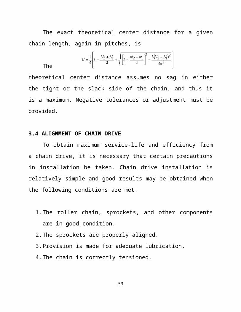
The exact theoretical center distance for a given chain length, again in
pitches, is
The theoretical
center distance assumes no sag in either the tight or the slack side of the chain, and
thus it is a maximum. Negative tolerances or adjustment must be provided.
3.4 ALIGNMENT OF CHAIN DRIVE
To obtain maximum service-life and efficiency from a chain drive, it is
necessary that certain precautions in installation be taken. Chain drive installation
35

is relatively simple and good results may be obtained when the following
conditions are met:
1. The roller chain, sprockets, and other components are in good condition.
2. The sprockets are properly aligned.
3. Provision is made for adequate lubrication.
4. The chain is correctly tensioned.
a) Condition of Components
Shafting, bearings, and foundations should be supported rigidly to maintain
the initial alignment. Roller chain should be free of grit and dirt. Wash chain in
kerosene when required.
b) Drive Alignment
Misalignment results in uneven loading across the width of the chain and
may cause roller link plate and sprocket tooth wear. Drive alignment involves two
things: parallel shaft alignment and axial sprocket alignment.
Shafts should be parallel and level. This condition may be readily checked
by the use of a feeler bar, and a machinist's level. It there is axial movement
of the shaft, lock the shaft in the normal running position before aligning the
sprockets.
36

(fig. 3.1 aligning shafts))
Normally, it is good practice to align the sprockets as close to the shaft
bearing as possible.
On drives with long spans, it may be necessary to support the chain with a
plank or bar as the connection is made.
Sprocket axial alignment can be checked with a straight edge which will
extend across the finished sides of the two sprockets. Normally, it is good
practice to align the sprockets as close to the shaft bearing as possible. For
long center distances, use a taut cord, or wire long enough to extend beyond
each of the sprockets.
fig 3.2 aligning sprockets
c) Installing the Chain37

Recheck all preceding adjustments for alignment and make certain all
setscrews, bolts and nuts are tight. Fit chain around both sprockets and bring the
free ends together on one sprocket for connection, the sprocket teeth will locate the
chain end links. Install the connecting link, and connecting link cover plate, and
the spring clip or coffer pins. On larger pitch chains or heavy multiple strand, it
may be necessary to lock the sprockets for this operation. After more research was
done the perception of using more than three blades was no longer a factor.
Currently, the most recent windmills are equipped with two or three blades.
When press fit cover plates are used, be careful not to drive the plate on so far as to
grip the roller links. Stiff joints can result if this is done. On drives with long spans,
it may be necessary to support the chain with a plank or bar as the connection is
made.
d) Chain Tension
Check chain tension to be certain the slack span has 4-6% mid-span movement in
horizontal drives and 2-3% in vertical drives.
Fig 3.3 terminology of sprocket
38

3.5 ROLLER CHAIN:
Fig 3.4 roller chain
39

Fig 3.5 Duplex Sprocket
3.5 SELECTION OF ROLLER CHAIN DRIVES
The following data should be taken into consideration while selecting roller
chain drives
a) Horsepower to be transmitted
b) RPM of the driving and driven sprocket (speed ratio)
c) Load classification
d) Space limitations if any
e) Driven machine
f) Source of power
If the pitch centre distance and number of teeth on both driving and driven
sprockets are known, you can use the following formula, tables and charts to
calculate chain lengths.40
3.5.1 SELECTION PROCEDURE
For maximum service life, smooth operation and optimum performance, the
following points should be considered, while determining the number of teeth in
the pinion.
a) As most drives have an even number of pitches in the chain, the use of a
pinion with an odd number of teeth ensures even distribution of chain and
wheel tooth wear.
b) Pinions for normal, stead drives should generally not have less than 17 teeth,
the reason being that a chain forms a polygon around the pinion. When the
pinion speed is constant, the chain speed is subject to regular cyclic
variation. The percentage of cyclic variation becomes less marked as the
number of teeth increases – and in fact becomes insignificant for the
majority of applications when the number of teeth in the pinion exceeds 17.
c) A minimum of 23 teeth is recommended on moderate shock drives where
the speed of the pinion exceeds 50 % of the maximum rated speed, and for
heavy shock drives where the speed of the pinion exceeds 25% of the
maximum rated speed.
d) The pinion should be heated to HV 10- 550 for smooth drives where the
pinion speeds exceeds 70% of the maximum speed and operates under full
horsepower rating. For heavy shock drives, the pinion be treated in all cases.
3.5.2 DETERMINE CHAIN LENGTH:
41

Compute the length of chain required using the formula given below. I
possible, adjust the centre distance , so that the length of chin required is always in
an even number of pitches. For optimum life of the chain and sprockets the centre
distance between the two sprockets should be 30 to 50 times the chain pitch.
where,
L- Chain length in pitches
P- Chain pitch
C- Contemplated centre distance
N- Number of teeth on large sprocket
n - Number of teeth on small sprocket
fig. 3.6 lifting tackle- frame (1)
42

fig. 3.7 lifting tackle- frame (2)
3.5.3 MATERIAL SPECIFICATIONS:
Type Material
Sprocket Duplex Sprocket Alloy Steel(C43)
Chain Roller chain Stainless steel
Hook Slip hook
Grab hook
Stainless steel
Chain Sling - Alloy Steel
43

Pin - Mild steel
Bush - Stainless steel
Rollers - Stainless steel
Link Plates - Alloy Steel(C20)
CHAPTER 4
CALCULATION
4.1 SELECTION OF NUMBER OF TEETH ON SPROCKET
Transmission ratio; i= 1
Driver sprocket, z1= 30
Driven sprocket, z2= 30
4.2 SELECTION OF STANDARD PITCH
Standard pitch, p= 15.875 mm
4.3 SELECTION OF CHAIN
44

Chain type: Duplex chain DR50 (from table 1.0)
4.4 CALCULATION OF SERVICE FACTOR
Service factor, ks= k1.k2.k3.k4.k5.k6
From tables 1.1, 1.2, 1.3, 1.4, 1.5, 1.6, 1.7
k1= 1.25
k2= 1.25
k3= 0.8
k4= 1
k5= 0.8
k6= 1.25
Service factor, ks= 1.25 x 1.25 x 0.8 x 1 x 0.8 x 1.25
Service factor, ks= 1.25
4.5 DETERMINATION OF LOAD
Load, PT = 450 kg = 450 x 9.81
Load, PT = 4414.5 N
Design Load = Load x service factor
Design Load = PT x ks
Design Load = 4414.5 x 1.25
Design Load = 5518.12 N
4.6 CALCULATION OF WORKING FACTOR OF SAFETY
Factor of safety = Breaking Load/ Design Load
Breaking Load = 4440 kgf= 44400N
Factor of safety = 44400/5518.1245

Factor of safety = 8.4
4.7 CHECK FACTOR OF SAFETY
Minimum value of factor of safety = 7 (from table 2.0)
Working factor of safety = 8.4
Working Factor of safety> Minimum Factor of safety
Hence design is safe.
4.8 CHECK BEARING STRESS
Velocity, v = z1pN/6
v = 30 x 15.875 x 50/60
v= 396.87 mm/s
v = 0.39 m/s
Bearing Area = 140mm2
Weight per metre = 1.78kgf
Power transmitted basis of breaking load, N= Q x v/ (102.n.ks)
Where,
Q- Breaking Load= 4440 kgf
Power, N= 4440 x 0.39 / (102 x 7 x 1.25)
Power, N= 1.94 kW
Bearing stress,
σ =102.ks.N/A.V46

σ = 102 x 1.25 x 1.94/ 140 x 0.39
σ = 29.6 N/mm2
Allowable bearing stress = 35 N/mm2 (from table 2.1)
Allowable bearing stress > Induced Stress
4.9 CALCULATION OF LENGTH OF CHAIN
Number of links, lp= 2ap + (z1+z2)/2 + [(z2 – z1/2π)2 / ap]
ap = ao/p
ap = 3000/15.875
ap = 188.97mm
where, ao- centre distance
ap- approximate centre distance in multiple of pitches
Number of links,
lp = 2 x 188.97 + [(30+30)/2]
lp = 407.94mm ≈ 410mm
lp = 410mm
Actual length = lp x p
Actual length = 410 x 15.875
Actual length = 6508.75mm ≈ 6510mm
4.10 CALCULATION OF ACTUAL CENTRE DISTANCE
Actual centre distance,
a = [(e * p) + √(e2 – 8m)] / 4
(z1 = z2 = 30)
So, m = 0
e = lp – [(z1 + z2/2)]
e = 410 – [(30 + 30)/2]47

e = 380
Actual centre distance, a = (380 x 15.875) + √(3802 – 8 x 0)
Actual centre distance, a = 3016.25mm ≈ 3020 mm
4.11 CALCULATION OF SPROCKET DIAMETER
Inner diameter of sprocket,
d = p/sin(180/z)
d = 15.875/(sin 180/30)
d = 151.87mm ≈ 152mm
d = 152mm
Roller diameter, Dr = 10.16mm
Outer diameter of sprocket,
D = d+ 0.8Dr
D = 152 + (0.8 x 0.16)
D = 160mm
Pitch angle,
α = 360/z
α = 360/30
α = 12o
Centrifugal tension,
Pc = mv2
Pc = 1.75 x 0.392
Pc = 0.28 kN
Pc = 28 N
4.12 CHAIN SLING CALCULATION
Safe Working load = 1800kg48

Safe Working Load, SWL = D2 x G x 0.3
where, G- grade 60 chain sling (alloy steel)
D- diameter
D2 x 60 x 0.3 = 1800
D2 = 1800/(60 x 0.3)
D2 = 55.56
D = √55.56
D = 7.76mm ≈ 8mm
Diameter of chain sling, D = 8mm
4.13 TABULATION:
Table 1.0 (Specifications of chain)
Table 1.1 (Load factor, k1)
49

Table 1.2 (Factor for distance regulation, k2)
Table 1.3 (Factor for centre distance of sprockets, k3)
50

Table 1.4 (Factor for position of sprockets, k4)
Table 1.6 (Lubrication factor, k5)
Table 1.7 (Rating factor, k6)
Table 2.0 (Factor of safety)51

PitchP,
mm
Speed of rotation of small sprocket, rpm
<50 200 400 600 800 1000 1200 1600 2000 2400 2800
9.52512.7
15.875
7.0 7.8 8.55 9.35 10.2 11.0 11.7 13.2 14.8 16.3 18.0
Pitchp, mm
Speed of rotation of small sprocket, rpm
<50 200 400 600 800 1000 1200 1600 2000 2400 2800
9.52512.7
15.875
35 31.5 28.7 26.2 24.2 22.4 21.0 18.5 16.5 15 13.7
Table 2.1 (Allowable Bearing Stress)
52
CHAPTER 5
WORKING
5.1 WORKING
In this technique, two sprockets (spr c and spr d) are additionally coupled
with the sprocket (a) and sprocket (b). The sprockets are coupled using shafts. The
sprockets (c) and (d) are linked with a chain drive (duplex chain). The ends of the
chain are attached with hooks, which is used to lift the hub. Due to heavy weight
at one side of hub, the lifting process becomes unbalance. When hub slides at the
right side of the tackling frame, the sprocket (c) and (d) will rotates at clockwise
direction. During this rotation, the power will be transmitted from sprocket (c) and
(d) to sprocket (a) and (b) respectively.
However, the rotation of sprocket (a) and (b) leads to move the disc plates
located at the cross bar of frame. When the disc plate moves through a certain
distance, the hub weight would be balanced.
5.2 ADVANTAGES
It will reduce the time consumption of work.
It improves work efficiency.
Less maintenance.
Self-balancing method performs the operation much faster than with manual
labour, this improves overall productivity.
53
Mechanical load brake assures braking even under overload conditions.
The design assures low headroom and this makes close trolley approaches
possible.
Hoist motor features aluminum alloy cast housing for optimal motor heat
dissipation and to reduce overall hoist weight.
Pushbutton pendant with emergency stop is durable, light weight and water
proof.
5.3FUTURE MODIFICATIONS
In future, the motorized trolley may be replaced into electromagnetic trolley
for better performance.
The electric motor lifting method may be replaced with hydraulic system to
save electrical energy.
Electromagnetic brakes may be installed in the travelling rail of trolley
instead of rubber stopper.
54

CHAPTER 6
CONCLUSION
Sometimes in our day-to-day life somewhere and sometime we will have the
need to carry a heavy load from one place to another. This happens more often in
various industries, particularly manufacturing industries. In rare instances we use
manpower or manual chain hoist, but when there is a constant need to do such
operations frequently and regularly then we need to think about an another option,
and that is self balancing lifting tackle.
On designing the self balanced lifting tackle which is driven by electrical
power, the reduction of time consumption of work, utilization of labour as well as
labour cost and increase in the production rate is achieved. Thus the working
efficiency as well as safety are ensured by this self balanced lifting tackle and is
successfully designed. It is easier and simple compared to the existing design. At
the same time the output is increased and the accuracy is maintained as the same.
The new design is flexible in design and can easily replace the conventional
design.
55

CHAPTER 7
REFERENCE
In the process of designing we went through several books and websites.
These are mentioned below:
7.1 BOOKS
Maitra G.M., Prasad L.V., “Hand book of Mechanical Design”, II Edition,
Tata McGraw-Hill, 2001.
Bhandari V.B., “Design of Machine Elements”, Tata McGraw-Hill
Publishing Company Ltd., 2004.
Hamrock B.J., Jacobson B., Schmid S.R., “Fundamentals of Machine
Elements”, McGraw-Hill Book Co., 2009
Ugural A.C., “Mechanical Design, An Integrated Approach”, McGraw-Hill,
2003
7.2 WEBSITES
www.firstgear.com
www.efunda.com
www.adamsmachinery.com
www.ansi.org
en.wikipedia.org
56
Related Documents