1 DESIGN OF SEGMENTAL TUNNEL LINING IN AN EARTHQUAKE ZONE Weng Lee Chow , Sek Kwan Tang, Swei Yeh Tong AMBERG & TTI Engineering Pte Ltd, 2 International Business Park #11-01 The Strategy, Singapore 609930 Keywords: design, tunnel lining, earthquake INTRODUCTION This paper presents the findings from the design of a 5.8m internal diameter reinforced concrete segmental lining using 2D FEM analysis where pseudo-static loadings (the use of “g” value) are used in an attempt to simulate earthquake loadings on the system. The segmental tunnel lining design was carried out for Contract BC-24 of Phase II Delhi Metro Line. Background and project description Contract BC-24 includes the construction of 3 underground stations using cut-and-cover method and 4.1km of twin bored tunnel using earth pressure balance (EPB) type tunnel boring machines (TBMs) from Central Secretariat to Badarpur Corridor of Phase II Delhi Metro Line. It also includes the construction of cross passages and an intervention shaft (IVS). GEOTECHNICAL CONSIDERATIONS Ground conditions The site is in an area of quaternary sediments classified as Older Alluvium. The geological map does not indicate rock outcrop within the BC-24 alignment. Figure 1 presents the alignment of BC- 24 plotted on the geological map of Delhi. The Older Alluvium is believed to be oxidised fluvial sediments comprising of silt, clay and micaceous sand with disseminated nodules and bands of kankar laid down during the middle or upper Pleistocene periods. Silt-clay and sand are the two major facies recognised in this sediment. The alignment of bored tunnel comprises of the followings: Fill - Made ground of up to 5 meters in thickness is found at certain section of the alignment. The Silt Layer - Underlying the fill, the ground condition in the site comprises mainly of yellowish – brownish silt layer from Older Alluvium. This layer is the dominant layer for the whole of the tunnel alignment. A borehole carried out at the interface of bored tunnel and J.Nehru Station showed isolated layers of silty sand around the tunnel crown and tunnel invert levels. No bedrock is encountered, within the depth of investigation, in the boreholes carried out for the purpose of tunnelling. However, boreholes carried out in the cut and cover tunnel location towards the interface with an adjacent contract showed quartzite bedrock at shallow depth. Measured readings from water standpipes showed that the groundwater table ranges from 4m to 17m below existing ground level.

Welcome message from author
This document is posted to help you gain knowledge. Please leave a comment to let me know what you think about it! Share it to your friends and learn new things together.
Transcript

1
DESIGN OF SEGMENTAL TUNNEL LINING IN AN EARTHQUAKE ZONE
Weng Lee Chow, Sek Kwan Tang, Swei Yeh Tong
AMBERG & TTI Engineering Pte Ltd, 2 International Business Park #11-01 The Strategy, Singapore 609930
Keywords: design, tunnel lining, earthquake INTRODUCTION This paper presents the findings from the design of a 5.8m internal diameter reinforced concrete segmental lining using 2D FEM analysis where pseudo-static loadings (the use of “g” value) are used in an attempt to simulate earthquake loadings on the system. The segmental tunnel lining design was carried out for Contract BC-24 of Phase II Delhi Metro Line. Background and project description Contract BC-24 includes the construction of 3 underground stations using cut-and-cover method and 4.1km of twin bored tunnel using earth pressure balance (EPB) type tunnel boring machines (TBMs) from Central Secretariat to Badarpur Corridor of Phase II Delhi Metro Line. It also includes the construction of cross passages and an intervention shaft (IVS). GEOTECHNICAL CONSIDERATIONS Ground conditions The site is in an area of quaternary sediments classified as Older Alluvium. The geological map does not indicate rock outcrop within the BC-24 alignment. Figure 1 presents the alignment of BC-24 plotted on the geological map of Delhi. The Older Alluvium is believed to be oxidised fluvial sediments comprising of silt, clay and micaceous sand with disseminated nodules and bands of kankar laid down during the middle or upper Pleistocene periods. Silt-clay and sand are the two major facies recognised in this sediment. The alignment of bored tunnel comprises of the followings: Fill - Made ground of up to 5 meters in thickness is found at certain section of the alignment. The Silt Layer - Underlying the fill, the ground condition in the site comprises mainly of yellowish – brownish silt layer from Older Alluvium. This layer is the dominant layer for the whole of the tunnel alignment. A borehole carried out at the interface of bored tunnel and J.Nehru Station showed isolated layers of silty sand around the tunnel crown and tunnel invert levels. No bedrock is encountered, within the depth of investigation, in the boreholes carried out for the purpose of tunnelling. However, boreholes carried out in the cut and cover tunnel location towards the interface with an adjacent contract showed quartzite bedrock at shallow depth. Measured readings from water standpipes showed that the groundwater table ranges from 4m to 17m below existing ground level.
2
Figure 1 – Geology along the alignment of BC-24
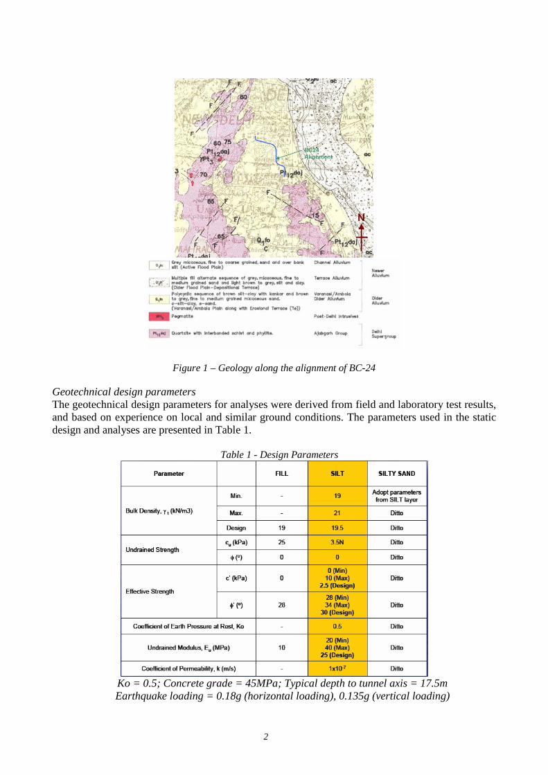
Geotechnical design parameters The geotechnical design parameters for analyses were derived from field and laboratory test results, and based on experience on local and similar ground conditions. The parameters used in the static design and analyses are presented in Table 1.
Table 1 - Design Parameters
Ko = 0.5; Concrete grade = 45MPa; Typical depth to tunnel axis = 17.5m Earthquake loading = 0.18g (horizontal loading), 0.135g (vertical loading)

3
In order to carry out dynamic analysis in the tunnel lining design, appropriate dynamic parameters of the soils have to be estimated. These include the shear wave velocity of the soil and rock medium, low strain dynamic shear modulus, shear modulus variation with strain and soil damping variation with strain. In addition, seismic data from previous seismic activities provides useful information with regards to wave acceleration and propagation or damping characteristics appropriate for the ground condition envisaged to be encountered. The following data was obtained for the dynamic analysis:
(a) The peak ground acceleration recorded is about 3.5m/s2 from (b) Seismic data from Roorkee Station, about 150km away from Delhi. Figure 2 shows the
locations of the various Strong Motion Accelerograph (SMA) Network. Roorkee Station is about 160km from Chamoli, of which was adopted as the reference earthquake source.
(c) Peak acceleration recorded at Roorkee Station for the Chamoli Earthquake is 0.55 m/s2. (d) As sensitivity study, seismic data from another SMA station Gopeshwar, about 20km
from Chamoli was used. The peak acceleration recorded at this station is about 3.5m/s2. (e) Shear modulus, as derived from seismic test from BC-16, ranges from 100 MPa to
1000MPa, over a depth from ground surface to about 30m below ground surface.
Figure 2 - Locations of strong motion accelerographs (SMA) networks
ANALYSIS AND DESIGN Design approach The segmental tunnel lining design was carried out using 2D finite element (FE) program Plaxis to obtain the stresses on the tunnel lining. Mohr Coulomb model was adopted and the soil material type is taken to be drained. The tunnel linings are modelled with hinges to simulate the joints between the 5 segments and a keystone. The design consists of various parametric studies to determine the most critical load case with respect to water table, presence of surcharge, K0 value, lining thickness, seismic forces and the depth of tunnel. The maximum bending moment and its corresponding axial force are then used to

4
determine the reinforcement required for the particular load case. Pseudo static loadings (the use of “g” value) are then used in an attempt to simulate earthquake loadings on the system where applicable. In addition, as a design validation case for Plaxis without considering the effects of earthquake loading, the results from Plaxis was also compared against the results from the empirical closed form solution of Muir-Wood (modified by Curtis). Earthquake loading using pseudo static load method In this method, the seismic loads are treated as equivalent pseudo-static loads. The dynamic earth pressure loads induced by seismic activity are dynamically applied in increments and the effects are combined with either the active or at-rest static soil pressures acting on the underground structure. New Delhi is located in Zone IV of Seismic Zoning Map of India. It was stated that Zone IV has fairly high seismicity with general occurrence of earthquakes of magnitude 5 – 6, a few of magnitudes 6 – 7 and occasional incidence of 7.5 – 8.0 magnitude of shocks. The tunnel lining are also required to be designed to forces equivalent to Modified Mercalli VII event in service condition. As indicated in IS 1893 Part 1 (2002), the Zone Factor, Z is 0.24. By applying a depth factor (IS 1893 Part 1 - 2002, pg 16, Clause 6.4.4), the effective peak ground acceleration can be reduced to 0.75*0.24 = 0.18g for a typical depth of 17.5m below ground level in the horizontal direction. For the vertical direction, 0.135g was adopted based on Youssef et al (2001). However, in order to simulate a full dynamic response of the tunnel lining using the equivalent pseudo-static method, correlation between the dynamic and equivalent pseudo-static method has to be carried out. Correlation with dynamic analysis SHAKE 91 Program and Plaxis Version 8 are used in the correlation exercise. SHAKE 91 Program is a DOS Program used to conduct equivalent linear seismic response analyses of horizontally layered soil deposits. The soil profile is idealised as a system of homogeneous, visco-elastic sub-layers of infinite horizontal extent. The response of this system is calculated considering vertically propagating shear waves. In the program, an equivalent linear procedure is used to account for the nonlinearity of the soil using an iterative procedure to obtain values for the modulus and damping that are compatible with the equivalent uniform strain induced in each subsoil layers. Plaxis Version 8 Program is a finite element program which has the capability of simulating the dynamic load using real earthquake data. The dynamic loading is usually applied at the bottom of the model resulting in shear waves that propagates upwards. The program is able to analyse the propagation of shear waves through the soil and its influence on underground structures. Absorbent boundaries are also specified at both sides of the model to absorb the increments of stresses on the boundaries caused by the dynamic loading, that would otherwise be reflected inside the soil body. Figure 3 below shows the Plaxis mesh use in the correlation exercise.

5
Figure 3 - Plaxis mesh used for study and correlation for propagation of shear waves
Figure 4 - Correlation of acceleration-time curve between SHAKE and Plaxis Figure 4 above shows a comparison of the acceleration-time curve between the SHAKE model and the Plaxis model. The results indicated a good match between the two programs. Input Data For the dynamic analysis conducted in the SHAKE model, the actual time history of an earthquake data was input at 70m below ground level (assuming rock layer). The dynamic shear modulus Gmax of 500MPa was assumed for the entire soil layer. This 500MPa is the weighted average obtained from the downhole seismic tests conducted at an adjacent site from ground level to 30m below ground level. A sensitivity study was also conducted for 1000MPa (maximum value derived from the seismic tests). The SHAKE program was first used to derive the acceleration at the ground surface adopting the earthquake load. The tunnel was not input in SHAKE because of the limitation of the program. Through the soil medium, the acceleration of the earthquake load was amplified when the waves reached the ground surface. This response for Delhi Silt is shown in Figure 5 below. Different typical soil types of varying relationship of G/Gmax and Damping Ratio versus Percent Strain were considered in the analysis (please see Figures 6 and 7). In a dynamic analysis, it is known that the shear modulus G and damping ratio of the soil will change with respect to change in the strain resulted from the earthquake load. From the SHAKE model, it was found that upper

6
bound of G/Gmax curve and lower bound of Damping Ratio of the various soil types gives the largest acceleration at the ground surface. The SHAKE model was then calibrated adopting a fixed equivalent damping ratio of 5% and Gmax of 500MPa and this was found to obtain a similar acceleration at the ground surface as that of the soil with upper bound of G/Gmax and the soil with lower bound of Damping Ratio. Hence, the 5% damping and shear modulus of 500MPa was input in finite element program Plaxis for the dynamic analysis which includes the tunnel lining which is modelled as beam elements. The shear modulus of soil was initially adopted as 10MPa at the stage of excavation and installation of the tunnel lining. During the dynamic analysis, the shear modulus was changed to 500MPa to reflect the dynamic nature of the soil behaviour.
Figure 5 - Acceleration-time curve at depth and at ground surface calibrated from dynamic analysis
Figure 6 - Plot of G/Gmax versus Percent Strain used in model calibration

7
Figure 7 - Plot of Damping Ratio versus Percent Strain used in model calibration
RESULTS AND FINDINGS Results from pseudo-static approach Figure 8 presents the results from the Plaxis program using pseudo-static approach. Figure 9 presents the results of the dynamic analysis.
Figure 8 - Forces in tunnel lining with no earthquake loading

8
Figure 9 - Forces in tunnel lining with pseudo-static earthquake loading Previous Figure 5 shows the acceleration-time curve at both bottom and top of the model. The maximum acceleration amplifies from 0.55m/s2 at the bottom (or rock surface) to 1.7m/s2 at the ground surface. With this amplification, the structural forces acting on the tunnel lining due to the dynamic loading increases slightly. However, the structural forces are still less than that predicted from the pseudo-static model. Sensitivity study Two additional sensitivity studies of the dynamic effects were also considered, one case (Case 1) adopting higher shear modulus of 1000MPa and another case (Case 2) adopting a stronger earthquake response recorded at Gopeshwar Station, about 20km from the earthquake at Chamoli. The peak acceleration recorded at this station is about 3.5m/s2. It was known that higher shear modulus will increase the acceleration. The results are shown in Figures 8 and 9. In this case, the maximum acceleration amplifies from 0.55m/s2 at the bottom (or rock surface) to 2.0m/s2 at the ground surface. There is no significant difference in the structural forces on the lining, as compared to the case of shear modulus of 500MPa.

9
Figure 8 - Acceleration-time curve for sensitivity study (Case 1 – 2 times higher shear modulus)
Figure 9 - Acceleration-time curve for sensitivity study (Case 2 – Very strong earthquake) However, as compared to the case without earthquake loading, results from Case 2 which produces a maximum peak ground acceleration of 5.8m/s2, showed significant increases of structural forces in the lining. The highest response was especially observed for the shear force, i.e. about 35% more. In comparison with pseudo-static analysis, the bending moment only increases by about 4% and the axial force are about 10%. Structural check for the bending capacity is found to be adequate for the forces induced. A separate check on the shear was also conducted and the shear reinforcement is found to be adequate, i.e. no collapse of the tunnel lining will occur. It is to be noted that this is an extreme case of the earthquake loading acting on the tunnel lining, of which the occurrence is more likely to be in Delhi Zone V rather than Zone IV which BC-24 project is located. In summary, the structural forces in the tunnel lining is summarised in Table 2.

10
Table 2 - Summarised results from empirical Muir-Wood (modified Curtis) method and pseudo-static method
from finite element Plaxis program
Method Soil Type Earthquake
Data Gmax (MPa)
Max Peak Ground
Acceleration (m/s2)
Max Bending Moment (kNm/m)
Max Shear Force
(kN/m)
Max Axial Force
(kN/m)
Empirical (Muir-Wood and
Curtis)
Mohr-Coulomb
- - - 112 148 1263
Plaxis Mohr-
Coulomb
Pseudo-static Earthquake
Load 10 - 138 113 1350
Plaxis Mohr-
Coulomb No Earthquake 10 - 116 92 1190
Plaxis Mohr-
Coulomb Chamoli Roorkee
500 dynamic
1.7 116 94 1190
Sensitivity Studies
Plaxis Mohr-
Coulomb Chamoli Roorkee
1000 dynamic
2.0 116 95 1200
Plaxis Mohr-
Coulomb Chamoli
Gopeshwar 500
dynamic 5.8 143 153 1490
CONCLUSIONS In order to be able carry out a reliable pseudo-static analysis in Plaxis for the design of segmental tunnel lining for BC-24, correlation with a full dynamic analysis using SHAKE was carried out. The results obtained from the pseudo-static analysis were compared with those obtained from static analysis using Muir-Wood (modified by Curtis). It was shown that pseudo-static analysis predicts a higher structural force on the tunnel lining as expected. This paper illustrated that with appropriate dynamic field data of the soil and measured dynamic responses from a seismic event, an appropriate correlation with dynamic response can be carried out reliably. A pseudo-static analysis can then be carried out effectively to obtain the induced forces onto the tunnel lining due to a seismic or earthquake event. ACKNOWLEDGEMENTS The authors would like to thank and acknowledge the co-operation and permission from the main contractor, Italian-Thai Development (ITD) JV and the client, DMRC for the publication of this paper.

11
REFERENCES
Downhole seismic test results from Geotechnical Investigation Report for DMRC BC-16 Contract, Report No. IGS/CEC-SOMA/DMRC BC-16/01.
Earthquake Data from COSMOS Virtual Data Centre.
I.M. Idriss & J.I. Sun (1992), “User’s Manual for SHAKE 91”.
P.B. Schnabel, J. Lysmer, H.B. Seed (1972), “SHAKE, A computer program for earthquake response analysis of horizontally layered Sites”, Report No. EERC 72-12, College of Engineering, University of California, Berkeley, California.
S. Mukhopadhyay, Y. Pandey, R. Dharmaraju, P.K.S. Chauhan, P. Singh & A. Dev (2002), “Seismic Microzonation of Delhi for Ground-Shaking Site Effects”, Current Science, Vol. 82, No.7, 10 April 2002, pp. 877-881.
V. Gupta, H.G. Poulos & S.G. Reid, “Seismic Micro-Zonation of Delhi”.
Y. Pandey, R. Dharmaraju, P.K.S. Chauhan & B. Chidanand (2003), “Preliminary Seismic Microzonation Map of Delhi”.
Y. Pandey, R. Dharmaraju & P.K.S. Chauhan (2001), “Estimation of Source Parameters of Chamoli Earthquake, India”, Proc. Indian Acad. Sci. (Earth Planet. Sci.), 110, No. 2, June 2001, pp.171-177.
Youssef M A Hashash, Jeffrey J. Hook, Birger Schmidt and John I-Chian Yao. “Seismic design and analysis of underground structures”, Tunnelling and Underground Space Technology 16 (2001).
Related Documents