Design of Roadway Design of Roadway Drainage Systems Drainage Systems Using Geocomposite Using Geocomposite Drainage Layers Drainage Layers by by Barry R. Christopher, Ph.D., P.E. Barry R. Christopher, Ph.D., P.E.

Design of Roadway Drainage Systems Using Geocomposite Drainage Layers by Barry R. Christopher, Ph.D., P.E.
Dec 18, 2015
Welcome message from author
This document is posted to help you gain knowledge. Please leave a comment to let me know what you think about it! Share it to your friends and learn new things together.
Transcript

Design of Roadway Design of Roadway Drainage SystemsDrainage Systems
Using Geocomposite Drainage Using Geocomposite Drainage LayersLayers
by by
Barry R. Christopher, Ph.D., P.E.Barry R. Christopher, Ph.D., P.E.
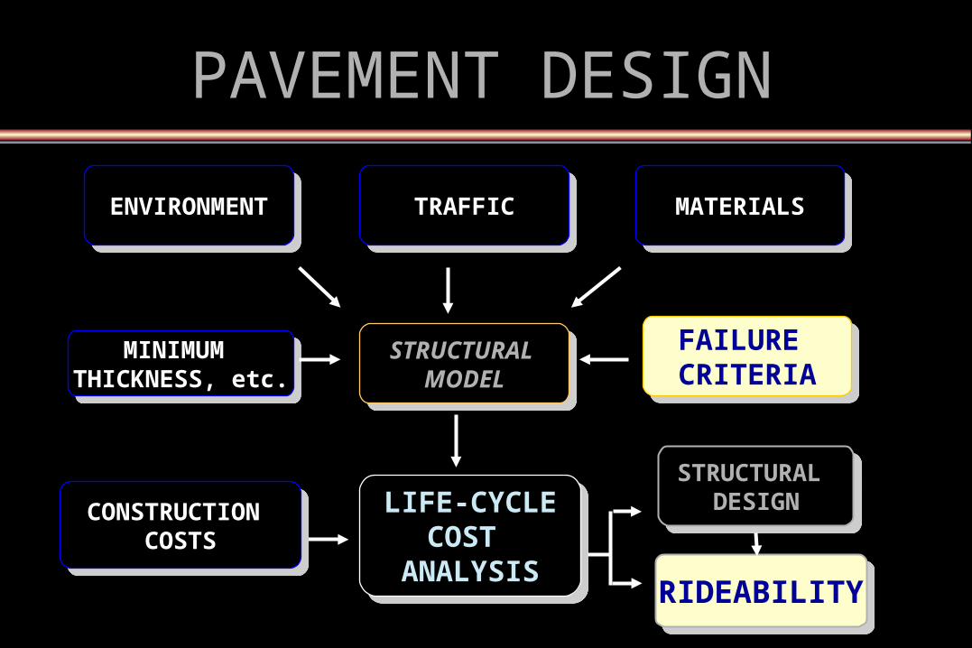
PAVEMENT DESIGNPAVEMENT DESIGN
TRAFFICTRAFFIC
LIFE-CYCLECOST
ANALYSIS
LIFE-CYCLECOST
ANALYSIS
FAILURE CRITERIA
FAILURE CRITERIA
MINIMUM THICKNESS, etc.
MINIMUM THICKNESS, etc.
ENVIRONMENTENVIRONMENT
STRUCTURAL MODEL
STRUCTURAL MODEL
MATERIALSMATERIALS
CONSTRUCTION COSTS
CONSTRUCTION COSTS
RIDEABILITYRIDEABILITY
STRUCTURAL DESIGN
STRUCTURAL DESIGN
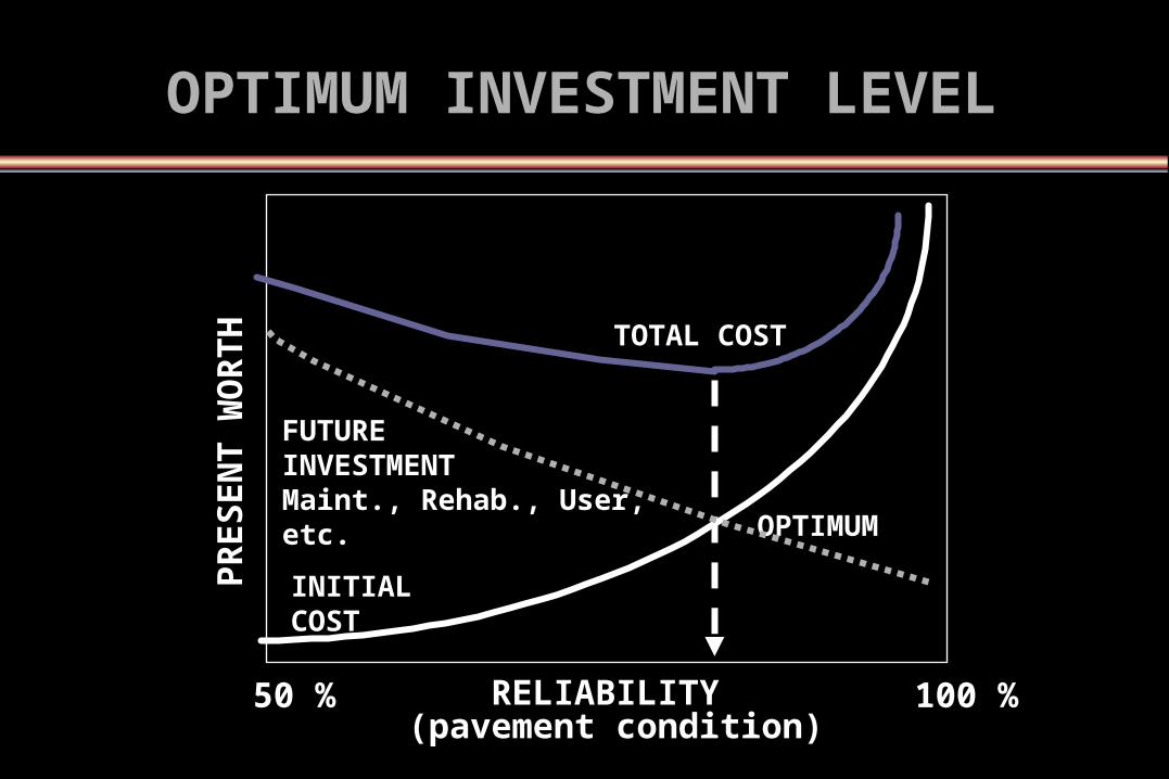
OPTIMUM INVESTMENT LEVELOPTIMUM INVESTMENT LEVEL
RELIABILITY (pavement condition)
PR
ES
EN
T W
OR
TH
OPTIMUM
100 %50 %
TOTAL COST
FUTURE INVESTMENT Maint., Rehab., User, etc.
INITIAL COST

CONSIDERATIONSCONSIDERATIONSIN PAVEMENT DESIGNIN PAVEMENT DESIGN
Continuous & Rapid Deterioration with TimeRepeated & Dynamic LoadingDifferent Load Magnitudes & ConfigurationsTraffic Distribution and GrowthChange Materials Properties &
CharacteristicsDrainageDrainageContamination of Road Materials
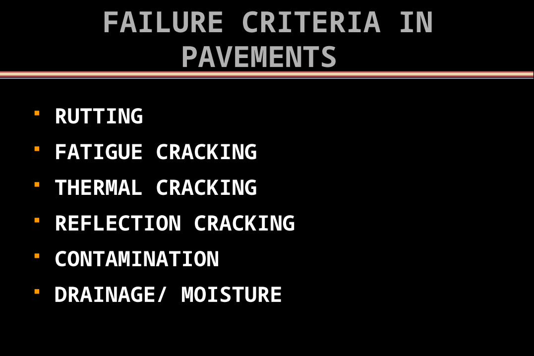
FAILURE CRITERIA IN FAILURE CRITERIA IN PAVEMENTSPAVEMENTS
RUTTING
FATIGUE CRACKING
THERMAL CRACKING
REFLECTION CRACKING
CONTAMINATION
DRAINAGE/ MOISTURE
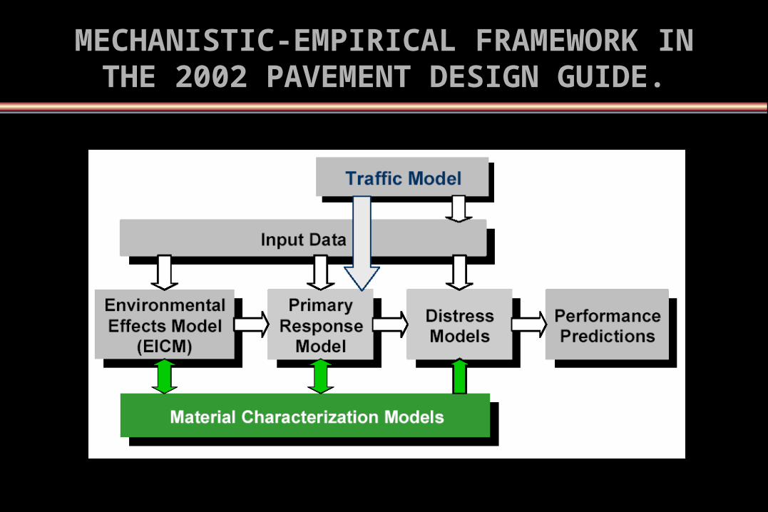
MECHANISTIC-EMPIRICAL FRAMEWORK IN MECHANISTIC-EMPIRICAL FRAMEWORK IN THE 2002 PAVEMENT DESIGN GUIDE.THE 2002 PAVEMENT DESIGN GUIDE.

Temperature
Precipitation
Humidity
Depth to Water Table
Frost Susceptibility
Capillary rise Potential
ENVIRONMENTAL / CLIMATICENVIRONMENTAL / CLIMATIC FACTORSFACTORS

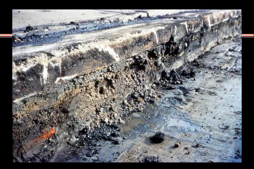
Water in the Pavement Structure
PrimaryCause ofDistress
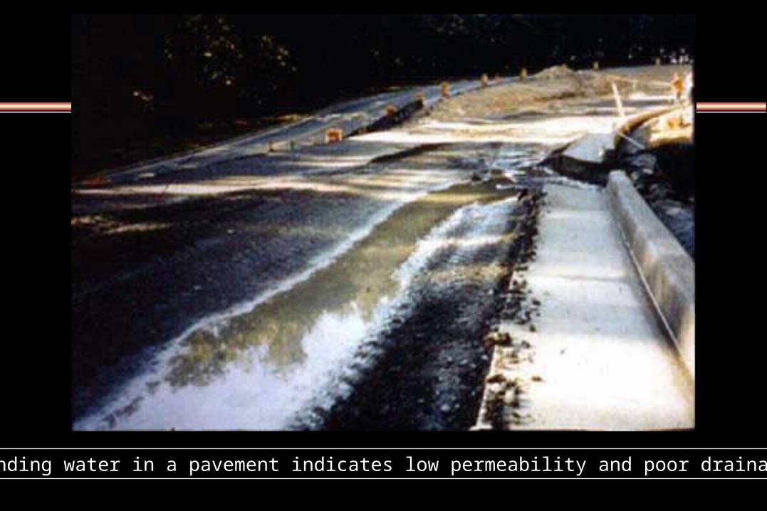
Standing water in a pavement indicates low permeability and poor drainage Standing water in a pavement indicates low permeability and poor drainage
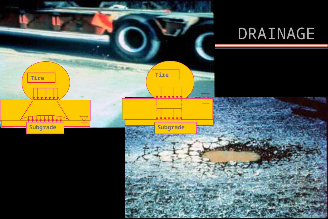
TireTire
Subgrade Subgrade
DRAINAGEDRAINAGE
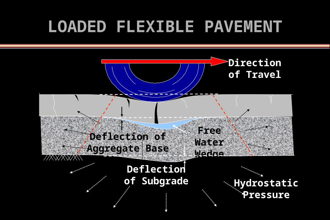
LOADED FLEXIBLE LOADED FLEXIBLE PAVEMENTPAVEMENT
Deflection of Aggregate Base
Free Water Wedge
Hydrostatic Pressure
Deflection of Subgrade
Direction of Travel

Under traffic loading, water and base material squirting up through joint in Under traffic loading, water and base material squirting up through joint in PCC pavementPCC pavement

Loaded PCC PavementLoaded PCC Pavement
Free Water Hydrostatic Pressure or Water Jet
Direction of Traffic
Direction of Traffic
Water is Violently Displaced Carrying Suspended Fines
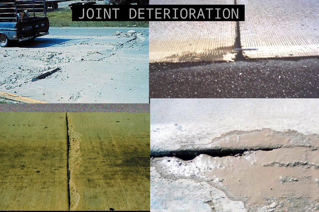
JOINT DETERIORATIONJOINT DETERIORATION

Water in Pavements SummaryWater in Pavements Summary
• Stripping in HMA
• Loss of Subgrade Support
• Reduction of Granular Layer Stiffness
• Erosion of Cement-Treated Base Layers
• Reduction in the Pavement Service Life If Base Is Saturated for Sometime
• Debond between Layers

Three important components for a Three important components for a good pavement designgood pavement design
DrainageDrainage
DrainageDrainage
DrainageDrainage


AASHTO Drainage DefinitionsAASHTO Drainage Definitions
Quality of Drainage
Excellent
Good
Fair
Poor
Very Poor
Water Removed Within*
2 Hours
1 Day
1 Week
1 Month
Water will not Drain
AASHTO Guide for Design of Pavement Structures, 1993
*Based on time to drain*Based on time to drain

Crushed Crushed OutletOutlet
Clogged Clogged OutletOutlet
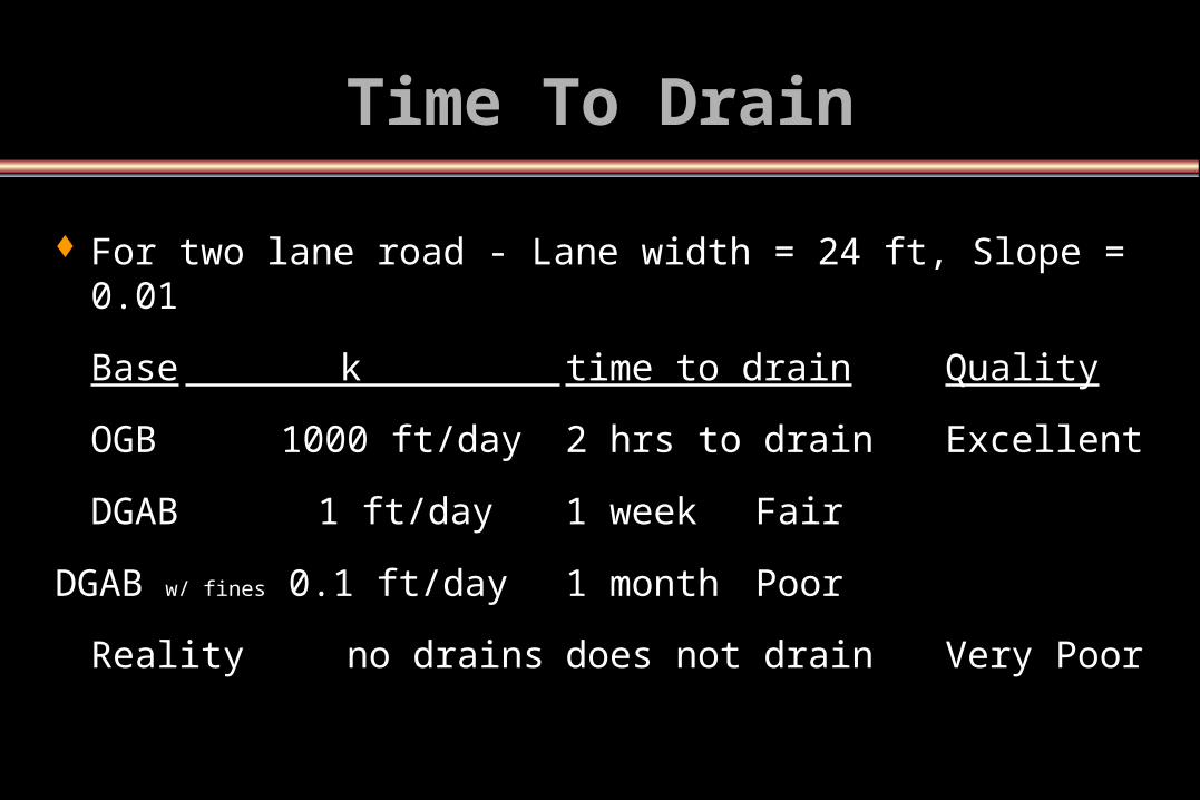
Time To DrainTime To Drain
For two lane road - Lane width = 24 ft, Slope = 0.01For two lane road - Lane width = 24 ft, Slope = 0.01
BaseBase k k time to draintime to drain QualityQuality
OGB OGB 1000 ft/day 1000 ft/day 2 hrs to drain2 hrs to drain ExcellentExcellent
DGABDGAB 1 ft/day 1 ft/day 1 week1 week FairFair
DGAB DGAB w/ finesw/ fines 0.1 ft/day 0.1 ft/day 1 month1 month PoorPoor
RealityReality no drains no drains does not draindoes not drain Very PoorVery Poor

Geocomposite Drain RequirementsGeocomposite Drain Requirements
Sufficient stiffness to support traffic without significant deformation under dynamic loading
Inflow capacity > infiltration from adjacent layers
Sufficient transmissivity to rapidly drain the pavement section and prevent saturation of the base
Sufficient air voids within geo-composite to provide a capillary break
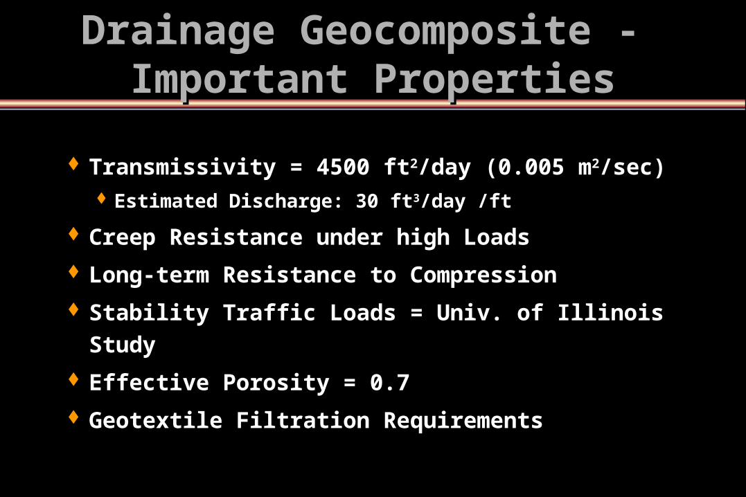
Drainage Geocomposite - Drainage Geocomposite - Important PropertiesImportant Properties
Transmissivity = 4500 ft2/day (0.005 m2/sec) Estimated Discharge: 30 ft3/day /ft
Creep Resistance under high Loads
Long-term Resistance to Compression
Stability Traffic Loads = Univ. of Illinois Study
Effective Porosity = 0.7
Geotextile Filtration Requirements
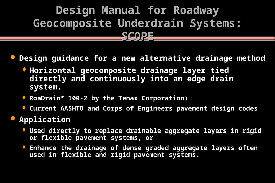
Design guidance for a new alternative drainage method Horizontal geocomposite drainage layer tied directly and
continuously into an edge drain system. RoaDrain™ 100-2 by the Tenax Corporation) Current AASHTO and Corps of Engineers pavement design codes
Application Used directly to replace drainable aggregate layers in rigid or flexible
pavement systems, or Enhance the drainage of dense graded aggregate layers often used in
flexible and rigid pavement systems.
Design Manual for Roadway Geocomposite Design Manual for Roadway Geocomposite Underdrain Systems: SCOPEUnderdrain Systems: SCOPE

Factors Affecting The DesignFactors Affecting The Design
Pavement slopes
Aggregate gradation
Porosity and effective porosity
Layer saturation
Permeability

Pavement SlopesPavement Slopes LR
S
SX
SR
AW
A
SxSR
SW LR
( )S S SR x= +2 2 0 5.
LR WSSX
=
1
2 0.5
Tan A SSX
( ) =
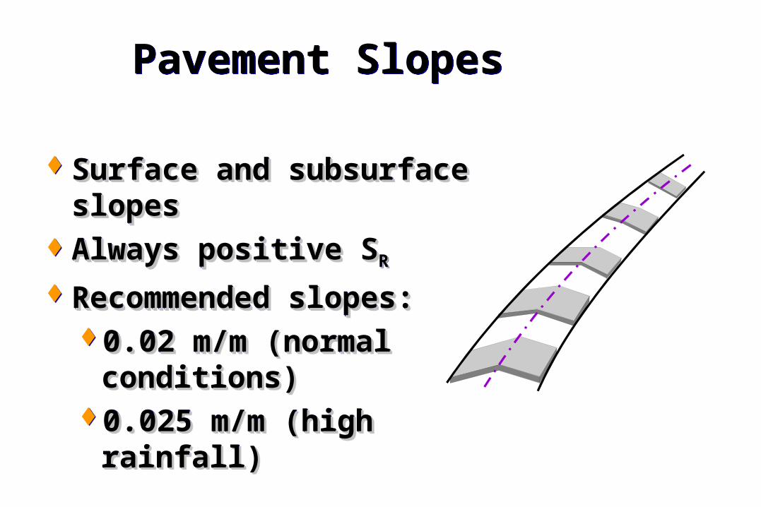
Pavement SlopesPavement Slopes
Surface and subsurface Surface and subsurface slopesslopes
Always positive SAlways positive SRR
Recommended slopes:Recommended slopes:0.02 m/m (normal 0.02 m/m (normal
conditions)conditions)0.025 m/m (high rainfall)0.025 m/m (high rainfall)
Surface and subsurface Surface and subsurface slopesslopes
Always positive SAlways positive SRR
Recommended slopes:Recommended slopes:0.02 m/m (normal 0.02 m/m (normal
conditions)conditions)0.025 m/m (high rainfall)0.025 m/m (high rainfall)

t = T x m x 24
Time-to-Drain CalculationTime-to-Drain Calculation
m-factor (days)Time factor
Time to drain (hrs)

Time to drainTime to drain
t = T x m x 24t = T x m x 24
where,where, t = time to drain in t = time to drain in hourshours
T = Time FactorT = Time Factor
m = “m” factorm = “m” factor
Sl = LRSr/HSl = LRSr/H

How to Estimate Time to Drain (t)How to Estimate Time to Drain (t)
Input: S and Sx W, H, k, d, Gsb, WL (for permeable base)
Interim Output: SR, LR, S1 {S1 = (LR x SR)/H} T for a desirable degree of drainage (U) N and Ne
N = [1- {d / (9.81 x Gsb)}] Ne = N x WL
“m” factor: m = (Ne x LR2) / (k x H)
Output: t = T x m x 24
Transmissivity

Time-to-Drain SensitivityTime-to-Drain Sensitivity
Factors affecting time-to-drain:
Effective porosity
Coefficient of permeability
Resultant slope
Resultant length
Permeable base thickness

0 305 610 915 1220
2
4
6
Coefficient of Permeability, m/day
Tim
e to
Dra
in,
hrs
Effect of kEffect of k
LR = 7.6 mH = 0.15 mU = 50%SR = 0.02 m/m

Effect of SEffect of SRR
.02 .04 .060
.2
.4
.6
.8
1
Resultant Slope, m/m
Tim
e to
Dra
in,
hrs
LR = 7.6 mH = 0.15 mU = 50%Ne = 0.25k = 915 m/day

Effect of LEffect of LRR
0 3.6 7.2 10.8 14.4
1
2
Resultant Length, m
Tim
e to
Dra
in,
hrs SR = 0.02 m/m
H = 0.15 mU = 50%Ne = 0.25k = 915 m/day
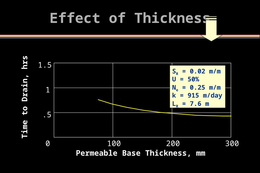
0 100 200 300
.5
1
1.5
Permeable Base Thickness, mm
Tim
e to
Dra
in,
hrs SR = 0.02 m/m
U = 50%Ne = 0.25 m/mk = 915 m/dayLR = 7.6 m
Effect of ThicknessEffect of Thickness
1
2
3
5
7
0.01 .03 .10 .30 .60
Slo
pe
Fac
tor
(S1)
Time Factor (T50)
T for U = 50% DrainedT for U = 50% Drained
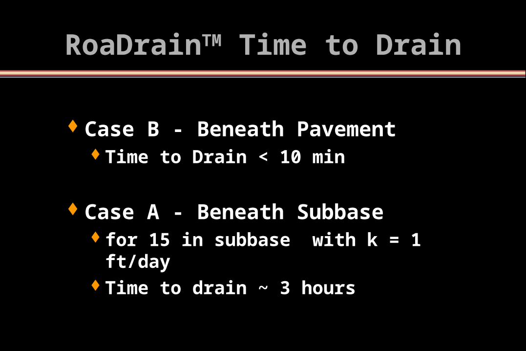
RoaDrainRoaDrainTMTM Time to Drain Time to Drain
Case B - Beneath PavementCase B - Beneath PavementTime to Drain < 10 minTime to Drain < 10 min
Case A - Beneath SubbaseCase A - Beneath Subbase for 15 in subbase with k = 1 ft/dayfor 15 in subbase with k = 1 ft/dayTime to drain ~ 3 hoursTime to drain ~ 3 hours
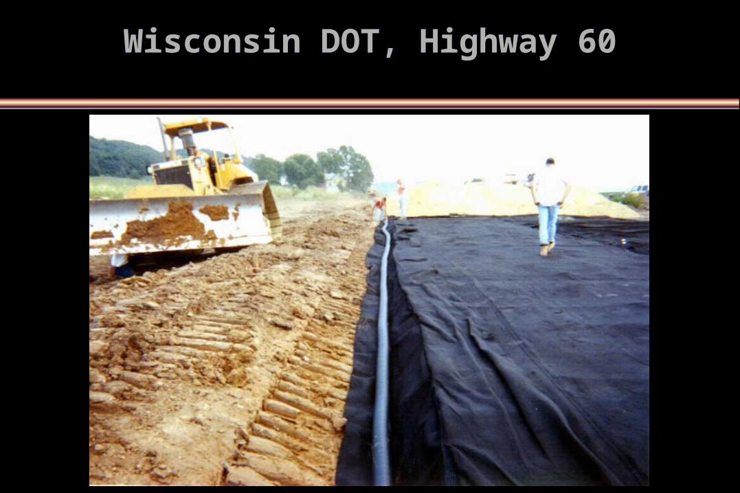
Wisconsin DOT, Highway 60Wisconsin DOT, Highway 60Wisconsin DOT, Highway 60Wisconsin DOT, Highway 60

GPR SurveyGPR Survey

ConclusionsConclusions The RoaDrainThe RoaDrainTMTM geocomposite drainage layer is an effective geocomposite drainage layer is an effective
alternative for pavement drainage.alternative for pavement drainage. Calculations based on time-to drain approach indicate:Calculations based on time-to drain approach indicate:
adequate infiltration rates to handle significant storm events.adequate infiltration rates to handle significant storm events. < 10 min. to drain the geocomposite layer. < 10 min. to drain the geocomposite layer. < 2 hours hours to drain the road even when placed beneath moderately < 2 hours hours to drain the road even when placed beneath moderately
permeable dense graded aggregate base. permeable dense graded aggregate base. i.e. excellent drainage based on AASHTO 1998 criteria.i.e. excellent drainage based on AASHTO 1998 criteria.
Five case studies in progress with 3 monitored study showing:Five case studies in progress with 3 monitored study showing: Excellent to good drainage following major storm events.Excellent to good drainage following major storm events. Geocomposite drains in subgrade found most effective, especially during Geocomposite drains in subgrade found most effective, especially during
spring thaw.spring thaw. Geocomposite drains facilitated construction and may have improved Geocomposite drains facilitated construction and may have improved
roadway section stiffness. roadway section stiffness. FEM study shows good potential for Strain Energy AbsorptionFEM study shows good potential for Strain Energy Absorption

QUESTIONS ?QUESTIONS ?
www.roadrainage.com
Related Documents