IEEE SENSORS JOURNAL, VOL. 7, NO. 3, MARCH 2007 455 Design of pH Sensors in Long-Period Fiber Gratings Using Polymeric Nanocoatings Jesus M. Corres, Ignacio R. Matias, Senior Member, IEEE, Ignacio del Villar, and Francisco J. Arregui, Member, IEEE Abstract—In this paper, two different pH sensors based on the deposition of nanometric scale polymeric films onto the surface of a long-period fiber grating (LPFG) have been studied and compared. An electrostatic self-assembled (ESA) method has been used to create sensitive films with an optimal overlay thickness. Two types of sensors have been designed: The first one is based on polyallylamine hydrochloride (PAH), polyacrylic acid (PAA), and the second one was done incorporating the pigment Prussian blue (PB) in the PAH/PAA matrix. A theoretical model of multilayer cylindrical waveguides based on coupled-mode theory has been used to predict the position of the attenuation bands as a function of the overlay thickness. Both sensors were tested and compared in terms of sensitivity and response time. A faster response was obtained with the introduction of PB particles in the polymeric matrix. Linear sensors in the pH range 4–7 were obtained, showing good repeatability and high sensitivity. Index Terms—Coupled-mode analysis, electrostatic self-as- sembly (ESA), long-period fiber gratings, nanophotonics, nanos- tructured materials, optical fiber sensors, pH sensor. I. INTRODUCTION T HE development of fiber-optic pH sensors is of practical importance in environmental, chemical and clinical fields. These type of sensors offer many advantages with respect to their electric counterparts such as the capacity for sensing in remote areas, the immunity to electromagnetic fields, and safety for in vivo pH measurement [1]. Several transmission-mode fiber structures, such as tapered optical fibers, holey fibers, omniguide fibers, hollow core fibers, etc., are susceptible to be used as transducers [2]–[9]. In the recent years, much research effort has been focused on long-period fiber gratings (LPFGs), which have found many applications in sensors because of their high sensitivity to the surrounding medium. The dependence of the resonance wavelength of the LPFGs with respect to the environment has been used to detect external refractive index variations [10]. Most of the fiber-optic pH sensors are based on a coating that is deposited onto the fiber surface, which changes with the pH. Manuscript received August 10, 2006; revised October 18, 2006; accepted November 20, 2006. This work was supported by Spanish CICYT TIC 2003- 00909 and Gobierno de Navarra Research Grants. The associate editor coordi- nating the review of this manuscript and approving it for publication was Prof. Denise Wilson. The authors are with the Electrical and Electronic Engineering Department, Public University of Navarra, 31006-Pamplona (Navarra), Spain (e-mail: [email protected]; [email protected]; [email protected]; [email protected]). Color versions of one or more of the figures in this paper are available online at http://ieeexplore.ieee.org. Digital Object Identifier 10.1109/JSEN.2007.891933 The reversible changes induced by the pH in the optical prop- erties or the sensing layer (absorbance, fluorescence, refractive index) are detected as a change in the optical power either trans- mitted or reflected. Some sensors are based on indicator dyes immobilized on the fiber surface [11]. The indicator dyes change their absorbance or luminescence depending on the pH. Others are based on hydrogels; materials that experience volumetric ex- pansions ranging between 5% and 250% in wet conditions, have been used for corrosion detection [12]–[15]. In the former type of sensors, there exist several problems coming from the difficulties to immobilize the dyes and the need for optical sources of enough power, usually in the ultravi- olet-visible (UV/VIS) spectral range [11], [16]–[18]. Although near-infrared (NIR) indicators have been used for the construc- tion of optical sensors [1], [19], taking advantage of the high efficiency and availability of NIR light sources, the use of indi- cators loaded on polymeric matrix are susceptible of leaching and bleaching of indicator [1], limiting in the practice sensor stability. Covalent attachment of dye molecules can solve this problem in part, but the method is complex and leads to loss of sensitivity [1]. Moreover, this deposition technique is complex and the thickness control rough. This last parameter is important because the thickness of the overlay contributes to an increase in the response time. The type of sensors proposed in this paper are based on the expansion (due to pH) of a nanofilm deposited with the elec- trostatic self-assembly deposition technique (ESA) [20] on an LPFG. The ESA technique has been one of the most frequently utilized methods for assembling organic or organic/inorganic hybrid thin films [21]. In this case, the thickness is azimuthally symmetric and controlled with nanoscale precision. Further- more, when the polyelectrolytes used in the deposition are weak (with a degree of dissociation and a linear charge density that depend greatly on the dipping solution pH), the properties of the film depend on the pHs of the solutions [21], [22]. Poly(acrylic acid) (PAA) poly-(allylamine hydrochloride) (PAH) multi- layers, used in this work, have been studied [23], showing that the organization and thickness depends sensitively on the pH of the adsorption solution. This means that it is possible to controllably alter the charge of the polyacid both during its adsorption onto a polycation layer and, what is more important for the use of this effect in the design of a pH sensor, once it has been deposited [22], [23]. As the charge control produces a change in the thickness of the coating, this affects its optical properties and consequently, the transmission characteristics of the LPFG. In this paper, it will be shown that this effect can be used to detect pH changes with high sensitivity and using standard in- frared light sources. In order to increase the response time of 1530-437X/$25.00 © 2007 IEEE

Welcome message from author
This document is posted to help you gain knowledge. Please leave a comment to let me know what you think about it! Share it to your friends and learn new things together.
Transcript
IEEE SENSORS JOURNAL, VOL. 7, NO. 3, MARCH 2007 455
Design of pH Sensors in Long-Period Fiber GratingsUsing Polymeric Nanocoatings
Jesus M. Corres, Ignacio R. Matias, Senior Member, IEEE, Ignacio del Villar, andFrancisco J. Arregui, Member, IEEE
Abstract—In this paper, two different pH sensors based on thedeposition of nanometric scale polymeric films onto the surfaceof a long-period fiber grating (LPFG) have been studied andcompared. An electrostatic self-assembled (ESA) method has beenused to create sensitive films with an optimal overlay thickness.Two types of sensors have been designed: The first one is based onpolyallylamine hydrochloride (PAH), polyacrylic acid (PAA), andthe second one was done incorporating the pigment Prussian blue(PB) in the PAH/PAA matrix. A theoretical model of multilayercylindrical waveguides based on coupled-mode theory has beenused to predict the position of the attenuation bands as a functionof the overlay thickness. Both sensors were tested and comparedin terms of sensitivity and response time. A faster response wasobtained with the introduction of PB particles in the polymericmatrix. Linear sensors in the pH range 4–7 were obtained, showinggood repeatability and high sensitivity.
Index Terms—Coupled-mode analysis, electrostatic self-as-sembly (ESA), long-period fiber gratings, nanophotonics, nanos-tructured materials, optical fiber sensors, pH sensor.
I. INTRODUCTION
THE development of fiber-optic pH sensors is of practicalimportance in environmental, chemical and clinical fields.
These type of sensors offer many advantages with respect totheir electric counterparts such as the capacity for sensing inremote areas, the immunity to electromagnetic fields, and safetyfor in vivo pH measurement [1]. Several transmission-modefiber structures, such as tapered optical fibers, holey fibers,omniguide fibers, hollow core fibers, etc., are susceptible to beused as transducers [2]–[9]. In the recent years, much researcheffort has been focused on long-period fiber gratings (LPFGs),which have found many applications in sensors because of theirhigh sensitivity to the surrounding medium. The dependenceof the resonance wavelength of the LPFGs with respect to theenvironment has been used to detect external refractive indexvariations [10].
Most of the fiber-optic pH sensors are based on a coating thatis deposited onto the fiber surface, which changes with the pH.
Manuscript received August 10, 2006; revised October 18, 2006; acceptedNovember 20, 2006. This work was supported by Spanish CICYT TIC 2003-00909 and Gobierno de Navarra Research Grants. The associate editor coordi-nating the review of this manuscript and approving it for publication was Prof.Denise Wilson.
The authors are with the Electrical and Electronic Engineering Department,Public University of Navarra, 31006-Pamplona (Navarra), Spain (e-mail:[email protected]; [email protected]; [email protected];[email protected]).
Color versions of one or more of the figures in this paper are available onlineat http://ieeexplore.ieee.org.
Digital Object Identifier 10.1109/JSEN.2007.891933
The reversible changes induced by the pH in the optical prop-erties or the sensing layer (absorbance, fluorescence, refractiveindex) are detected as a change in the optical power either trans-mitted or reflected. Some sensors are based on indicator dyesimmobilized on the fiber surface [11]. The indicator dyes changetheir absorbance or luminescence depending on the pH. Othersare based on hydrogels; materials that experience volumetric ex-pansions ranging between 5% and 250% in wet conditions, havebeen used for corrosion detection [12]–[15].
In the former type of sensors, there exist several problemscoming from the difficulties to immobilize the dyes and theneed for optical sources of enough power, usually in the ultravi-olet-visible (UV/VIS) spectral range [11], [16]–[18]. Althoughnear-infrared (NIR) indicators have been used for the construc-tion of optical sensors [1], [19], taking advantage of the highefficiency and availability of NIR light sources, the use of indi-cators loaded on polymeric matrix are susceptible of leachingand bleaching of indicator [1], limiting in the practice sensorstability. Covalent attachment of dye molecules can solve thisproblem in part, but the method is complex and leads to loss ofsensitivity [1]. Moreover, this deposition technique is complexand the thickness control rough. This last parameter is importantbecause the thickness of the overlay contributes to an increasein the response time.
The type of sensors proposed in this paper are based on theexpansion (due to pH) of a nanofilm deposited with the elec-trostatic self-assembly deposition technique (ESA) [20] on anLPFG. The ESA technique has been one of the most frequentlyutilized methods for assembling organic or organic/inorganichybrid thin films [21]. In this case, the thickness is azimuthallysymmetric and controlled with nanoscale precision. Further-more, when the polyelectrolytes used in the deposition are weak(with a degree of dissociation and a linear charge density thatdepend greatly on the dipping solution pH), the properties of thefilm depend on the pHs of the solutions [21], [22]. Poly(acrylicacid) (PAA) poly-(allylamine hydrochloride) (PAH) multi-layers, used in this work, have been studied [23], showing thatthe organization and thickness depends sensitively on the pHof the adsorption solution. This means that it is possible tocontrollably alter the charge of the polyacid both during itsadsorption onto a polycation layer and, what is more importantfor the use of this effect in the design of a pH sensor, once ithas been deposited [22], [23]. As the charge control producesa change in the thickness of the coating, this affects its opticalproperties and consequently, the transmission characteristics ofthe LPFG.
In this paper, it will be shown that this effect can be used todetect pH changes with high sensitivity and using standard in-frared light sources. In order to increase the response time of
1530-437X/$25.00 © 2007 IEEE
456 IEEE SENSORS JOURNAL, VOL. 7, NO. 3, MARCH 2007
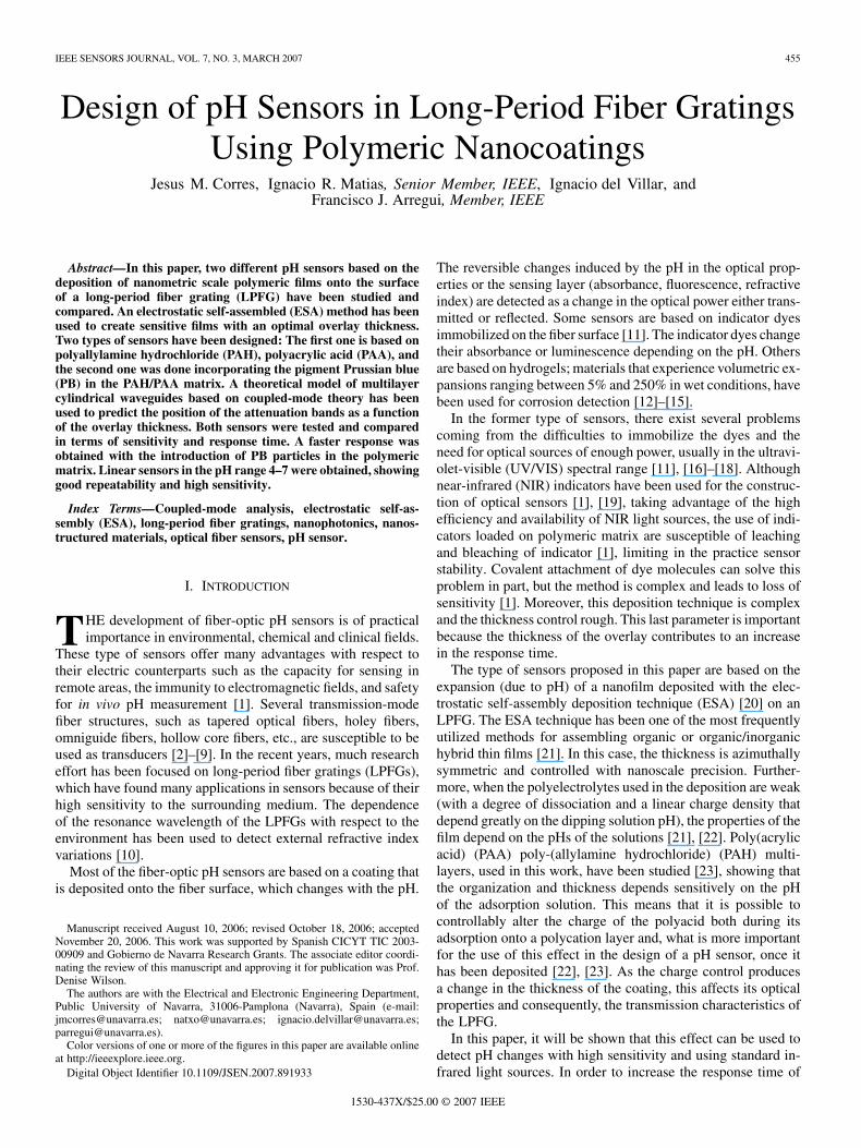
Fig. 1. Schematic of ESA deposition process.
the sensor, a more permeable overlay will be deposited usingthe pigment Prussian blue (PB). In this case, the purpose of in-troducing the pigment is not to change the absorbance or flu-orescence, but to increase the permeability of the film. It willbe demonstrated that this second design improves the sensor re-sponse times, but at the expense of decreasing their sensitivity.
The paper is organized as follows. In Section II, the ESAmethod is briefly described. Then, in Section III, the principleof operation is explained and predicted using a rigorous simu-lation method. In Section IV, some experimental results will bepresented in two different sensors with the only difference of theadding of a dye inside the nanofilm. Finally, some concludingremarks are given in Section V.
II. ELECTROSTATIC SELF-ASSEMBLED MONOLAYER PROCESS
Several methods can be used for the deposition of thesensitive nanolayers like physical and thermal evaporation,spin-coating, dip-coating, Langmuir–Blodgett, and ESA [20],[24]–[29]. The last two techniques permit accurate control ofthe growth. In this paper, the ESA method will be used due tosome of its advantages with respect to other methods of depo-sition. Among other advantages, ESA allows a precise controlof the thickness and permits the fabrication of azimuthallysymmetrical smooth and uniform coatings. The ESA process isa technique used to build up coatings on a variety of differentsubstrate materials such as ceramics, metals, and polymers ofdifferent shapes and forms, including planar substrates, prisms,and convex and concave surfaces. This method is based onthe construction of molecular multilayers by the electrostaticattraction between oppositely charged polyelectrolytes in eachmonolayer deposited and involves several steps [20], [24].The ESA film-deposition method is described schematically inFig. 1.
First, a substrate (in this case, the optical fiber) is cleaned andtreated to create a charged surface. The substrate is then exposedto a solution of a polyion of opposite charge for a short time(minutes) and, by adsorption, a monolayer of polyions is formedon the surface. In this way, the substrate is alternately dippedinto solutions of cationic and anionic polymers (or appropriatelycharged inorganic clusters) to create a multilayer thin film, apolyanion–polycation multilayer.
After each monolayer is formed, we rinse the sample in purewater to remove the excess of molecules that are not bound and
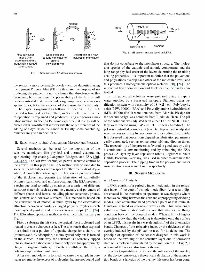
Fig. 2. pH sensor structure based on LPFG.
that do not contribute to the monolayer structure. The molec-ular species of the cationic and anionic components and thelong-range physical order of the layers determine the resultingcoating properties. It is important to notice that the polyanionsand polycations overlap each other at the molecular level, andthis produces a homogeneous optical material [20], [24]. Theindividual layer composition and thickness can be easily con-trolled.
In this paper, all solutions were prepared using ultrapurewater supplied by a Barnstead nanopure Diamond water pu-rification system with resistivity of 18 cm. Poly(acrylicacid) (MW. 90000) (PAA) and Poly(allylamine hydrochloride)(MW. 55000) (PAH) were obtained from Aldrich. PB dye forthe second design was obtained from Riedel de Haen. The pHof the solutions was adjusted with either HCl or NaOH. Then,they were filtered using 0.45- m PTFE filters (Acrodisc). ThepH was controlled periodically (each ten layers) and readjustedwhen necessary using hydrochloric acid or sodium hydroxide.It is observed that depositions depend on fabrication parameterseasily automated, such as temperature, pH, and dipping times.The repeatability of the process is favored in good part by usinga continuous in situ monitoring and by robotizing the ESAprocess. A layer-by-layer deposition robot (Riegler & KirsteinGmbH, Potsdam, Germany) was used in order to automate thedeposition process. The dipping time in the polyion and waterrinse solutions was 4 and 1 min, respectively.
III. SENSING MECHANISM
A. Theoretical Analysis
LPFGs consist of a periodic index modulation in the refrac-tive index of the core of a single-mode fiber. As a result, dipsare created in the transmission spectrum at wavelengths wherethere is a coupling between the core and copropagating claddingmodes. Each attenuation band presents a point of maximum at-tenuation, notated as resonance wavelength. This wavelengthvalue is in close relation with the one that satisfies the Braggcondition between the coupled modes. When a film of higherrefractive index than the cladding is deposited onto the surfaceof an LPFG, this results in a wavelength shift of the attenuationbands. Changes of the refractive index or the thickness of theoverlay induced by the pH can be used for its detection. Theprinciple of operation of the sensors designed in this work isbased on the swelling of the sensitive layer due to ionizationstate of its molecules modulated by the solution pH. In Fig. 2, ascheme of the sensor structure is shown.
In order to quantitatively observe the influence of the overlayon the device sensitivity, a theoretical calculation of the attenua-tion bands as a function of the overlay thickness has been done.
CORRES et al.: DESIGN OF PH SENSORS IN LPFGS USING POLYMERIC NANOCOATINGS 457
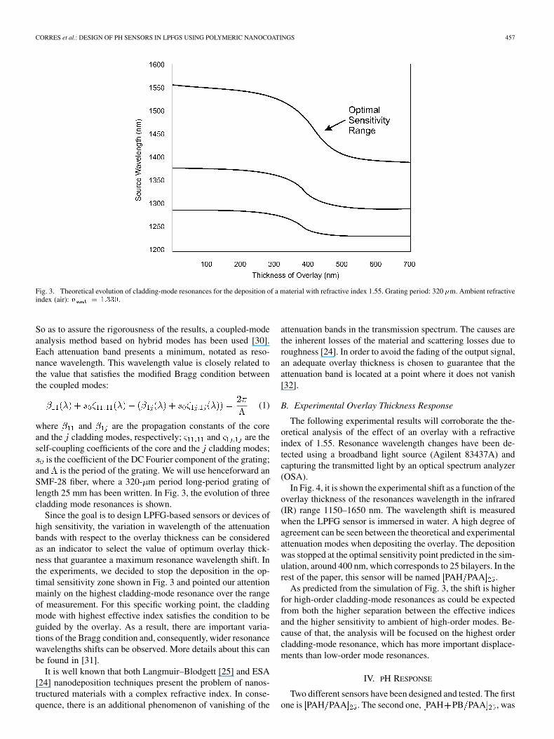
Fig. 3. Theoretical evolution of cladding-mode resonances for the deposition of a material with refractive index 1.55. Grating period: 320 �m. Ambient refractiveindex (air): n = 1:330.
So as to assure the rigorousness of the results, a coupled-modeanalysis method based on hybrid modes has been used [30].Each attenuation band presents a minimum, notated as reso-nance wavelength. This wavelength value is closely related tothe value that satisfies the modified Bragg condition betweenthe coupled modes:
(1)
where and are the propagation constants of the coreand the cladding modes, respectively; and are theself-coupling coefficients of the core and the cladding modes;
is the coefficient of the DC Fourier component of the grating;and is the period of the grating. We will use henceforward anSMF-28 fiber, where a 320- m period long-period grating oflength 25 mm has been written. In Fig. 3, the evolution of threecladding mode resonances is shown.
Since the goal is to design LPFG-based sensors or devices ofhigh sensitivity, the variation in wavelength of the attenuationbands with respect to the overlay thickness can be consideredas an indicator to select the value of optimum overlay thick-ness that guarantee a maximum resonance wavelength shift. Inthe experiments, we decided to stop the deposition in the op-timal sensitivity zone shown in Fig. 3 and pointed our attentionmainly on the highest cladding-mode resonance over the rangeof measurement. For this specific working point, the claddingmode with highest effective index satisfies the condition to beguided by the overlay. As a result, there are important varia-tions of the Bragg condition and, consequently, wider resonancewavelengths shifts can be observed. More details about this canbe found in [31].
It is well known that both Langmuir–Blodgett [25] and ESA[24] nanodeposition techniques present the problem of nanos-tructured materials with a complex refractive index. In conse-quence, there is an additional phenomenon of vanishing of the
attenuation bands in the transmission spectrum. The causes arethe inherent losses of the material and scattering losses due toroughness [24]. In order to avoid the fading of the output signal,an adequate overlay thickness is chosen to guarantee that theattenuation band is located at a point where it does not vanish[32].
B. Experimental Overlay Thickness Response
The following experimental results will corroborate the the-oretical analysis of the effect of an overlay with a refractiveindex of 1.55. Resonance wavelength changes have been de-tected using a broadband light source (Agilent 83437A) andcapturing the transmitted light by an optical spectrum analyzer(OSA).
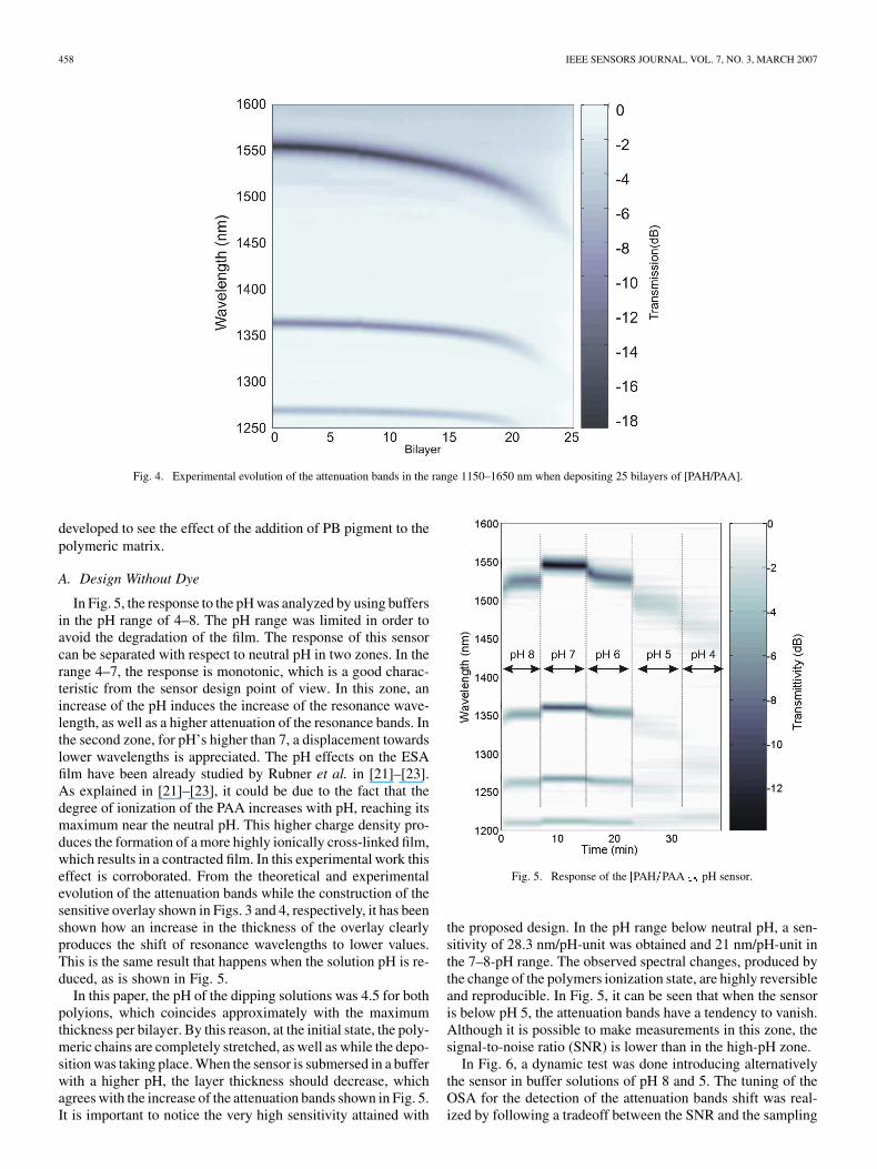
In Fig. 4, it is shown the experimental shift as a function of theoverlay thickness of the resonances wavelength in the infrared(IR) range 1150–1650 nm. The wavelength shift is measuredwhen the LPFG sensor is immersed in water. A high degree ofagreement can be seen between the theoretical and experimentalattenuation modes when depositing the overlay. The depositionwas stopped at the optimal sensitivity point predicted in the sim-ulation, around 400 nm, which corresponds to 25 bilayers. In therest of the paper, this sensor will be named PAH PAA .
As predicted from the simulation of Fig. 3, the shift is higherfor high-order cladding-mode resonances as could be expectedfrom both the higher separation between the effective indicesand the higher sensitivity to ambient of high-order modes. Be-cause of that, the analysis will be focused on the highest ordercladding-mode resonance, which has more important displace-ments than low-order mode resonances.
IV. PH RESPONSE
Two different sensors have been designed and tested. The firstone is PAH PAA . The second one, PAH PB PAA , was
458 IEEE SENSORS JOURNAL, VOL. 7, NO. 3, MARCH 2007
Fig. 4. Experimental evolution of the attenuation bands in the range 1150–1650 nm when depositing 25 bilayers of [PAH/PAA].
developed to see the effect of the addition of PB pigment to thepolymeric matrix.
A. Design Without Dye
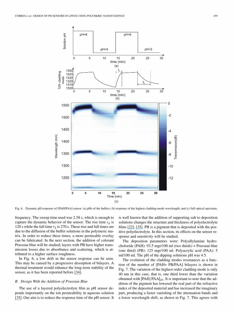
In Fig. 5, the response to the pH was analyzed by using buffersin the pH range of 4–8. The pH range was limited in order toavoid the degradation of the film. The response of this sensorcan be separated with respect to neutral pH in two zones. In therange 4–7, the response is monotonic, which is a good charac-teristic from the sensor design point of view. In this zone, anincrease of the pH induces the increase of the resonance wave-length, as well as a higher attenuation of the resonance bands. Inthe second zone, for pH’s higher than 7, a displacement towardslower wavelengths is appreciated. The pH effects on the ESAfilm have been already studied by Rubner et al. in [21]–[23].As explained in [21]–[23], it could be due to the fact that thedegree of ionization of the PAA increases with pH, reaching itsmaximum near the neutral pH. This higher charge density pro-duces the formation of a more highly ionically cross-linked film,which results in a contracted film. In this experimental work thiseffect is corroborated. From the theoretical and experimentalevolution of the attenuation bands while the construction of thesensitive overlay shown in Figs. 3 and 4, respectively, it has beenshown how an increase in the thickness of the overlay clearlyproduces the shift of resonance wavelengths to lower values.This is the same result that happens when the solution pH is re-duced, as is shown in Fig. 5.
In this paper, the pH of the dipping solutions was 4.5 for bothpolyions, which coincides approximately with the maximumthickness per bilayer. By this reason, at the initial state, the poly-meric chains are completely stretched, as well as while the depo-sition was taking place. When the sensor is submersed in a bufferwith a higher pH, the layer thickness should decrease, whichagrees with the increase of the attenuation bands shown in Fig. 5.It is important to notice the very high sensitivity attained with
Fig. 5. Response of the [PAH=PAA] pH sensor.
the proposed design. In the pH range below neutral pH, a sen-sitivity of 28.3 nm/pH-unit was obtained and 21 nm/pH-unit inthe 7–8-pH range. The observed spectral changes, produced bythe change of the polymers ionization state, are highly reversibleand reproducible. In Fig. 5, it can be seen that when the sensoris below pH 5, the attenuation bands have a tendency to vanish.Although it is possible to make measurements in this zone, thesignal-to-noise ratio (SNR) is lower than in the high-pH zone.
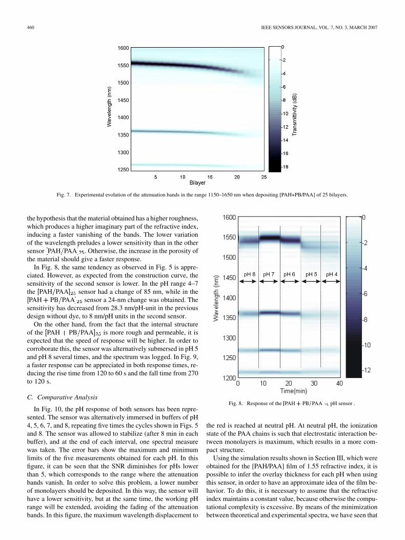
In Fig. 6, a dynamic test was done introducing alternativelythe sensor in buffer solutions of pH 8 and 5. The tuning of theOSA for the detection of the attenuation bands shift was real-ized by following a tradeoff between the SNR and the sampling
CORRES et al.: DESIGN OF PH SENSORS IN LPFGS USING POLYMERIC NANOCOATINGS 459
Fig. 6. Dynamic pH response of [PAH/PAA] sensor. (a) pHs of the buffers; (b) response of the highest cladding-mode wavelength; and (c) full optical spectrum.
frequency. The sweep time used was 2.58 s, which is enough tocapture the dynamic behavior of the sensor. The rise time is120 s while the fall time is 270 s. These rise and fall times aredue to the diffusion of the buffer solutions in the polymeric ma-trix. In order to reduce these times, a more permeable overlaycan be fabricated. In the next section, the addition of colorantPrussian blue will be studied; layers with PB have higher trans-mission losses due to absorbance and scattering, which is at-tributed to a higher surface roughness.
In Fig. 6, a low drift in the sensor response can be seen.This may be caused by a progressive desorption of bilayers. Athermal treatment would enhance the long-term stability of thesensor, as it has been reported before [34].
B. Design With the Addition of Prussian Blue
The use of a layered polyelectrolyte film as pH sensor de-pends importantly on the ion permeability in aqueous solution[35]. Our aim is to reduce the response time of the pH sensor. It
is well known that the addition of supporting salt to depositionsolutions changes the structure and thickness of polyelectrolytefilms [22], [35]. PB is a pigment that is deposited with the pos-itive polyelectrolyte. In this section, its effects on the sensor re-sponse and sensitivity will be studied.
The deposition parameters were: Polyallylamine hydro-choloride (PAH): 93.5 mgr/100 ml (two thirds) + Prussian blue(one third) (PB): 125 mgr/100 ml. Polyacrylic acid (PAA): 5ml/100 ml. The pH of the dipping solutions pH was 4.5.
The evolution of the cladding modes resonances as a func-tion of the number of [PAH+ PB/PAA] bilayers is shown inFig. 7. The variation of the highest order cladding mode is only40 nm in this case, that is, one third lower than the variationobtained with PAH PAA . It is important to note that the ad-dition of the pigment has lowered the real part of the refractiveindex of the deposited material and has increased the imaginarypart, producing a faster vanishing of the attenuation bands anda lower wavelength shift, as shown in Fig. 7. This agrees with
460 IEEE SENSORS JOURNAL, VOL. 7, NO. 3, MARCH 2007
Fig. 7. Experimental evolution of the attenuation bands in the range 1150–1650 nm when depositing [PAH+PB/PAA] of 25 bilayers.
the hypothesis that the material obtained has a higher roughness,which produces a higher imaginary part of the refractive index,inducing a faster vanishing of the bands. The lower variationof the wavelength preludes a lower sensitivity than in the othersensor PAH PAA . Otherwise, the increase in the porosity ofthe material should give a faster response.
In Fig. 8, the same tendency as observed in Fig. 5 is appre-ciated. However, as expected from the construction curve, thesensitivity of the second sensor is lower. In the pH range 4–7the PAH PAA sensor had a change of 85 nm, while in thePAH PB PAA sensor a 24-nm change was obtained. The
sensitivity has decreased from 28.3 nm/pH-unit in the previousdesign without dye, to 8 nm/pH units in the second sensor.
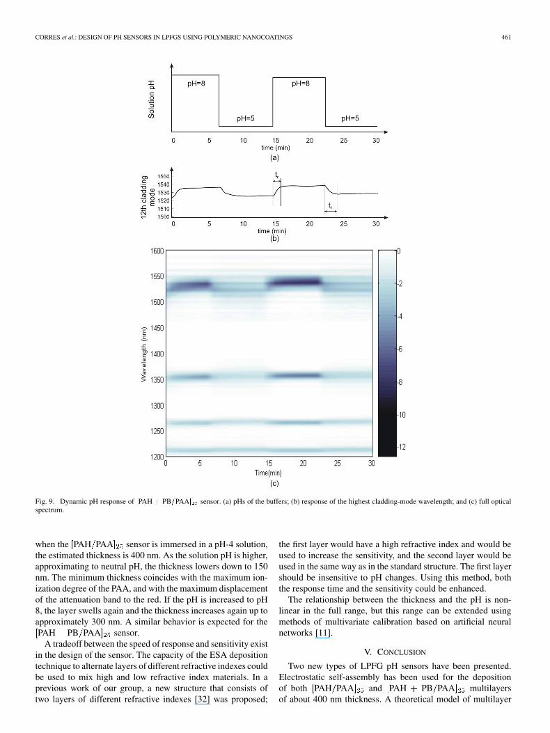
On the other hand, from the fact that the internal structureof the PAH PB PAA is more rough and permeable, it isexpected that the speed of response will be higher. In order tocorroborate this, the sensor was alternatively submersed in pH 5and pH 8 several times, and the spectrum was logged. In Fig. 9,a faster response can be appreciated in both response times, re-ducing the rise time from 120 to 60 s and the fall time from 270to 120 s.
C. Comparative Analysis
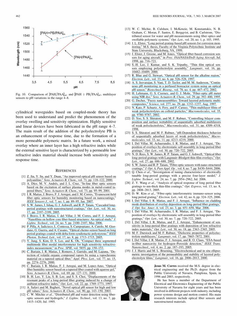
In Fig. 10, the pH response of both sensors has been repre-sented. The sensor was alternatively immersed in buffers of pH4, 5, 6, 7, and 8, repeating five times the cycles shown in Figs. 5and 8. The sensor was allowed to stabilize (after 8 min in eachbuffer), and at the end of each interval, one spectral measurewas taken. The error bars show the maximum and minimumlimits of the five measurements obtained for each pH. In thisfigure, it can be seen that the SNR diminishes for pHs lowerthan 5, which corresponds to the range where the attenuationbands vanish. In order to solve this problem, a lower numberof monolayers should be deposited. In this way, the sensor willhave a lower sensitivity, but at the same time, the working pHrange will be extended, avoiding the fading of the attenuationbands. In this figure, the maximum wavelength displacement to
Fig. 8. Response of the [PAH + PB=PAA] pH sensor .
the red is reached at neutral pH. At neutral pH, the ionizationstate of the PAA chains is such that electrostatic interaction be-tween monolayers is maximum, which results in a more com-pact structure.
Using the simulation results shown in Section III, which wereobtained for the [PAH/PAA] film of 1.55 refractive index, it ispossible to infer the overlay thickness for each pH when usingthis sensor, in order to have an approximate idea of the film be-havior. To do this, it is necessary to assume that the refractiveindex maintains a constant value, because otherwise the compu-tational complexity is excessive. By means of the minimizationbetween theoretical and experimental spectra, we have seen that
CORRES et al.: DESIGN OF PH SENSORS IN LPFGS USING POLYMERIC NANOCOATINGS 461
Fig. 9. Dynamic pH response of [PAH + PB=PAA] sensor. (a) pHs of the buffers; (b) response of the highest cladding-mode wavelength; and (c) full opticalspectrum.
when the PAH PAA sensor is immersed in a pH-4 solution,the estimated thickness is 400 nm. As the solution pH is higher,approximating to neutral pH, the thickness lowers down to 150nm. The minimum thickness coincides with the maximum ion-ization degree of the PAA, and with the maximum displacementof the attenuation band to the red. If the pH is increased to pH8, the layer swells again and the thickness increases again up toapproximately 300 nm. A similar behavior is expected for thePAH PB PAA sensor.
A tradeoff between the speed of response and sensitivity existin the design of the sensor. The capacity of the ESA depositiontechnique to alternate layers of different refractive indexes couldbe used to mix high and low refractive index materials. In aprevious work of our group, a new structure that consists oftwo layers of different refractive indexes [32] was proposed;
the first layer would have a high refractive index and would beused to increase the sensitivity, and the second layer would beused in the same way as in the standard structure. The first layershould be insensitive to pH changes. Using this method, boththe response time and the sensitivity could be enhanced.
The relationship between the thickness and the pH is non-linear in the full range, but this range can be extended usingmethods of multivariate calibration based on artificial neuralnetworks [11].
V. CONCLUSION
Two new types of LPFG pH sensors have been presented.Electrostatic self-assembly has been used for the depositionof both PAH PAA and PAH PB PAA multilayersof about 400 nm thickness. A theoretical model of multilayer
462 IEEE SENSORS JOURNAL, VOL. 7, NO. 3, MARCH 2007
Fig. 10. Comparison of [PAH=PAA] and [PAH + PB=PAA] multilayersensors to pH variations in the range 4–8.
cylindrical waveguides based on coupled-mode theory hasbeen used to understand and predict the phenomenon of theoverlay swelling and sensitivity optimization. Highly sensitiveand linear devices have been fabricated in the pH range 4–7.The main result of the addition of the polyelectrolyte PB isan enhancement of response time, due to the formation of amore permeable polymeric matrix. In a future work, a mixedoverlay where an inner layer has a high refractive index whilethe external sensitive layer is characterized by a permeable lowrefractive index material should increase both sensitivity andresponse time.
REFERENCES
[1] Z. Jin, Y. Su, and Y. Duan, “An improved optical pH sensor based onpolyaniline,” Sens. Actuators B, Chem., vol. 71, pp. 118–122, 2000.
[2] A. Díez, M. V. Andrés, and J. L. Cruz, “In-line fiber optic sensorsbased on the excitation of surface plasma modes in metal-coated ta-pered fibers,” Sens. Actuators B, Chem., vol. 73, pp. 95–99, 2001.
[3] I. R. Matias, J. Bravo, F. J. Arregui, and J. M. Corres, “Evanescent fieldfiber optic sensors for humidity monitoring based on nanocoatings,”IEEE Sensors J., vol. 7, no. 1, pp. 89–95, Jan. 2007.
[4] S. W. James, I. Ishaq, G. J. Ashwell, and R. P. Tatam, “Cascaded long-period gratings with nanostructured coatings,” Opt. Lett., vol. 30, no.17, pp. 2197–2199, 2005.
[5] J. Bravo, I. R. Matias, I. del Villar, J. M. Corres, and F. J. Arregui,“Nanofilms on hollow core fiber-based structures: An optical study,” J.Lightw. Technol., vol. 24, no. 5, pp. 2100–2107, May 2006.
[6] P. Pilla, A. Iadicieco, L. Contessa, S. Campopiano, A. Cutolo, M. Gior-dano, G. Guerra, and A. Cusano, “Optical chemo-sensor based on longperiod gratings coated with delta form syndiotactic polystyrene,” IEEEPhoton. Technol. Lett., vol. 17, no. 8, pp. 1713–1715, 2005.
[7] Y. Jung, S. Kim, D. S. Lee, and K. Oh, “Compact three segmentedmultimode fiber modal interferometer for high sensitivity refractive-index measurement,” in Proc. SPIE, vol. 5855, pp. 150–153.
[8] C. Bariain, I. R. Matias, I. Romero, J. Garrido, and M. Laguna, “De-tection of volatile organic compound vapors by using a vapochromicmaterial on a tapered optical fiber,” Appl. Phys. Lett., vol. 77, no. 15,pp. 2274–2276, 2000.
[9] C. Bariain, I. R. Matias, F. J. Arregui, and M. Lopez-Amo, “Opticalfiber humidity sensor based on a tapered fiber coated with agarose gel,”Sens. Actuators B, Chem., vol. 69, pp. 127–131, 2000.
[10] B. H. Lee, Y. Liu, S. B. Lee, and S. S. Choi, “Displacements of theresonant peaks of a long-period fiber grating induced by a change ofambient refractive index,” Opt. Lett., vol. 22, pp. 1769–1771, 1997.
[11] A. Safavi and M. Bagheri, “Novel optical pH sensor for high and lowpH values,” Sens. Actuators B, Chem., vol. 90, pp. 143–150, 2003.
[12] C. W. Mitchie et al., “Distributed pH and water detection using fiber-optic sensors and hydrogels,” J. Lightw. Technol., vol. 13, no. 7, pp.1415–1420, Jul. 1995.
[13] W. C. Michie, B. Culshaw, I. McKenzie, M. Konstantakis, N. B.Graham, C. Moran, F. Santos, E. Bergqvist, and B. Carlstrom, “Dis-tributed sensor for water and pH measurements using fiber optics andswellable polymeric systems,” Opt. Lett., vol. 20, no. 1, p. 103, 1995.
[14] J. L. Elster, “Long period grating-based pH sensors for corrosion mon-itoring,” M.S. thesis, Faculty of the Virginia Polytechnic Institute andState University, Blacksburg, VA, 1999.
[15] J. Elster, J. Greene, and M. Jones, “Optical fiber-based corrosion sen-sors for aging aircraft,” in Proc. FAA/NASA/DoD Aging Aircraft, Jul.1998, pp. 716–721.
[16] S.-H. Lee, J. Kumar, and S. K. Tripathy, “Thin film optical sen-sors employing polyelectrolyte assembly,” Langmuir, vol. 16, pp.10482–10489, 2000.
[17] R. Blue and G. Stewart, “Optical pH sensor for the alkaline region,”Electron. Lett., vol. 33, no. 6, pp. 526–528, 1997.
[18] A. S. Jeevarajan, S. Vani, T. D. Taylor, and M. M. Anderson, “Contin-uous pH monitoring in a perfused bioreactor system using an opticalpH sensor,” Biotechnol. Bioeng., vol. 78, no. 4, pp. 467–472, 2002.
[19] H. Lehmann, G. S. Czerney, and G. J. Mohr, “Fiber-optic pH meterusing NIR dye,” Sens. Actuators B, Chem., vol. 29, pp. 392–400, 1995.
[20] G. Decher, “Fuzzy nanoassemblies: Toward layered polymeric multi-composites,” Science, vol. 277, no. 29, pp. 1232–1237, Aug. 1997.
[21] N. Kato, P. Schuetz, A. Fery, and F. Caruso, “Thin multilayer films ofweak polyelectrolytes on colloid particles,” Macromolecules, vol. 35,pp. 9780–9787, 2002.
[22] D. Yoo, S. S. Shiratori, and M. F. Rubner, “Controlling bilayer com-position and surface wettability of sequentially adsorbed multilayersof weak polyelectrolytes,” Macromolecules, vol. 31, pp. 4309–4318,1998.
[23] S. S. Shiratori and M. F. Rubner, “pH-Dependent thickness behaviorof sequentially adsorbed layers of weak polyelectrolytes,” Macro-molecules, vol. 33, no. 11, pp. 4213–4219, 2000.
[24] I. Del Villar, M. Achaerandio, I. R. Matias, and F. J. Arregui, “De-position of overlays by electrostatic self-assembly in long-period fibergratings,” Opt. Lett., vol. 30, pp. 720–722, 2005.
[25] N. D. Rees, S. W. James, R. P. Tatam, and G. J. Ashwell, “Optical fiberlong-period gratings with Langmuir–Blodgett thin-film overlays,” Opt.Lett., vol. 27, pp. 686–688, 2002.
[26] S. W. James and R. P. Tatam, “Fibre optic sensors with nano-structuredcoatings,” J. Opt. A, Pure Appl. Op. , vol. 8, no. 7, pp. S430–S444, 2006.
[27] Q. Chen et al., “Investigation of tuning characteristics of electricallytunable long-period gratings with a precise four-layer model,” J.Lightw. Technol., vol. 24, no. 7, pp. 2954–2962, Jul. 2006.
[28] Z. Y. Wang et al., “Analysis of optical response of long period fibergratings to nm-thick thin-film coatings,” Opt. Express, vol. 13, no. 8,pp. 2808–2813, 2005.
[29] D. W. Kim et al., “Fibre-optic interferometric immuno-sensor usinglong period grating,” Electron. Lett., vol. 42, no. 6, pp. 324–325, 2006.
[30] I. Del Villar, I. R. Matias, and F. J. Arregui, “Influence on claddingmode distribution of overlay deposition on long-period fiber gratings,”J. Opt. Soc. Amer. A, vol. 23, no. 3, pp. 651–658, Mar. 2006.
[31] I. Del Villar, M. Achaerandio, I. R. Matias, and F. J. Arregui, “De-position of overlays by electrostatic self-assembly in long-period fibergratings,” Opt. Lett., vol. 30, no. 7, pp. 720–722, 2005.
[32] I. Del Villar, I. R. Matias, and F. J. Arregui, “Enhancement of sen-sitivity in long-period fiber gratings with deposition of low refractiveindex materials,” Opt. Lett., vol. 30, no. 18, pp. 2363–2365, 2005.
[33] M. F. Durstock and M. F. Rubner, “Dielectric properties of polyelec-trolyte multilayers,” Langmuir, vol. 17, pp. 7865–7872, 2001.
[34] I. Del Villar, I. R. Matías, F. J. Arregui, and R. O. Claus, “ESA-basedin-fiber nanocavity for hydrogen–Peroxide detection,” IEEE Trans.Nanotechnol., vol. 4, no. 2, pp. 187–193, 2005.
[35] J. J. Harris and M. L. Bruening, “Electrochemical and in situ ellipso-metric investigation of the permeability and stability of layered poly-electrolyte films,” Langmuir, vol. 16, pp. 2006–2013, 2000.
Jesus M. Corres received the M.S. degree in elec-trical engineering and the Ph.D. degree from thePublic University of Navarra, Pamplona, Spain, in1996 and 2003, respectively.
He has been a member of the Department ofElectrical and Electronics Engineering of the PublicUniversity of Navarra for eight years and has beeninvolved in different projects with industry, includingpower systems design and motion control. His mainresearch interests include optical fiber sensors andnanostructured materials.
CORRES et al.: DESIGN OF PH SENSORS IN LPFGS USING POLYMERIC NANOCOATINGS 463
Ignacio R. Matias (SM’03) received the M.S. andPh.D. degrees in electrical and electronic engineeringfrom the Polytechnic University of Madrid, Madrid,Spain, in 1992 and 1996, respectively.
He is currently a Professor at the Public Univer-sity of Navarra, Pamplona, Spain. He has coauthoredmore than 200 book chapters and journal and confer-ence papers related to optical fiber sensors and opticaldevices.
Dr. Matias currently serves as Associate Editor ofthe IEEE SENSORS JOURNAL.
Ignacio del Villar received the M.S. degree in elec-trical and electronic engineering and the Ph.D. degreefrom the Public University of Navarra (UPNA), Pam-plona, Spain, in 2002 and 2006, respectively.
During 2004, he was a Visiting Scientist at the In-stitut d’Optique Centre National de la Recherche Sci-entifique, Orsay, France, and in 2005, he was a Vis-iting Scientist in the Applied Physics Department ofthe University of Valencia, Valencia, Spain. He is cur-rently an Assistant Professor at the Public Univer-sity of Navarra. His research interests include anal-
ysis and fabrication of optical fiber sensors and nanostructures.Dr. Del Villar has served as a referee for the journals Physical Review B, Op-
tical Express, JOSA A, Optics Letters, the JOURNAL LIGHTWAVE TECHNOLOGY,the IEEE SENSORS JOURNAL, Sensors and Actuators B: Chemical, and Opticsand Laser Technology.
Francisco J. Arregui (M’04) received the M.S.degree in electrical engineering from the CatholicUniversity of Navarra, San Sebastian, Spain, in 1994and the Ph.D. degree from the Public University ofNavarra, Pamplona, Spain, in 2000.
He is currently a permanent Associate Professorwith the Public University of Navarra. During 1998,2000, and 2004, he was a Visiting Scientist at theFiber and Electro Optics Research Center, VirginiaPolytechnic Institute and State University, Blacks-burg, VA. His main research interests include optical
fiber sensors, sensor materials, and nanostructured materials.Dr. Arregui is an Associate Editor of the IEEE SENSORS JOURNAL. He is a
member of The International Society for Optical Engineers (SPIE).
Related Documents