1 Design of Heat Exchangers All rights reserved, Armando B. Corripio, 2014 Contents Design of Heat Exchangers...................................... 1 1. Enthalpy Balances on a Heat Exchanger ..................... 3 2. Calculation of the Enthalpy ............................... 5 Example 1. Enthalpy Balance on an Exchanger. ............... 6 3. Sizing the Exchanger ...................................... 7 4. Heat Transfer Coefficient ................................. 8 Example 2. Estimate of the Over-all Heat Transfer Coefficient .......................................................... 12 5. Heat Transfer Coefficients for Cylindrical Tubes ......... 13 5.1 Determination of the Wall Temperature ................. 15 Example 3. Estimate of Heat Transfer Coefficient in a Pipe Exchanger ................................................. 15 6. The Temperature Difference ............................... 16 6.1 Linear Temperature Profiles ........................... 17 Example 4. Comparison of Parallel vs. Countercurrent Flow. 20 6.3 Constant Temperature Profile .......................... 22 6.4 Nonlinear Temperature Profiles ........................ 25 Example 5. Sizing an Exchanger with a Nonlinear Temperature Profile ................................................... 25 6.5 Minimum Approach Temperature .......................... 29 7. Heat Exchanger Simulation ................................ 30 7.1 Simple Exchanger Models ............................... 31 7.2 Rigorous Heat Exchanger Models ........................ 31 8. Film Coefficients of Heat Transfer ....................... 32 8.1 Turbulent Flow inside Conduits without Phase Change ... 33 8.2 The Equivalent Diameter ............................... 34 Example 6. Size Aniline Cooler ............................ 35 8.3 Laminar Flow .......................................... 39 8.4 Condensing Vapors on Vertical Tubes ................... 39

Welcome message from author
This document is posted to help you gain knowledge. Please leave a comment to let me know what you think about it! Share it to your friends and learn new things together.
Transcript

1
Design of Heat Exchangers
All rights reserved, Armando B. Corripio, 2014
Contents Design of Heat Exchangers...................................... 1
1. Enthalpy Balances on a Heat Exchanger ..................... 3
2. Calculation of the Enthalpy ............................... 5
Example 1. Enthalpy Balance on an Exchanger. ............... 6
3. Sizing the Exchanger ...................................... 7
4. Heat Transfer Coefficient ................................. 8
Example 2. Estimate of the Over-all Heat Transfer Coefficient
.......................................................... 12
5. Heat Transfer Coefficients for Cylindrical Tubes ......... 13
5.1 Determination of the Wall Temperature ................. 15
Example 3. Estimate of Heat Transfer Coefficient in a Pipe
Exchanger ................................................. 15
6. The Temperature Difference ............................... 16
6.1 Linear Temperature Profiles ........................... 17
Example 4. Comparison of Parallel vs. Countercurrent Flow. 20
6.3 Constant Temperature Profile .......................... 22
6.4 Nonlinear Temperature Profiles ........................ 25
Example 5. Sizing an Exchanger with a Nonlinear Temperature
Profile ................................................... 25
6.5 Minimum Approach Temperature .......................... 29
7. Heat Exchanger Simulation ................................ 30
7.1 Simple Exchanger Models ............................... 31
7.2 Rigorous Heat Exchanger Models ........................ 31
8. Film Coefficients of Heat Transfer ....................... 32
8.1 Turbulent Flow inside Conduits without Phase Change ... 33
8.2 The Equivalent Diameter ............................... 34
Example 6. Size Aniline Cooler ............................ 35
8.3 Laminar Flow .......................................... 39
8.4 Condensing Vapors on Vertical Tubes ................... 39

2
8.5 Condensing Vapors on Horizontal Tubes ................. 40
8.6 Boiling Liquids ....................................... 41
9. Shell and Tube Heat Exchangers ........................... 42
9.1 Shell-side Film Coefficient without Phase Change ...... 45
9.2 Selecting the Number of Tube Passes ................... 47
9.3 Correction of Mean Temperature Difference for Multi-pass
Exchanger ................................................. 48
9.4 Correction of Mean Temperature Difference for Two Shell
Passes .................................................... 50
9.5 Cross Flow ............................................ 52
10. Quick Design of Heat Exchangers ........................ 52
Example 7. Estimate the area required for the aniline cooler
of Example 1 .............................................. 54
11. Quick Estimate of Exchanger Cost ....................... 55
Example 8. Estimate the cost of the heat exchanger of Example
1 ......................................................... 56
12. Detailed Design of a Heat Exchanger .................... 56
12.1 Fouling Resistance ................................... 57
12.2 Detailed Design Procedure ............................ 58
Example 9. Detailed design of aniline cooler of Example 1 . 59
Summary ..................................................... 63
Review Questions ............................................ 63
Problems .................................................... 64
Heat exchangers are used in chemical and refining processes to
Exchange heat between two process streams (called Cross-
exchangers)
Heat process streams (called heaters and furnaces)
Cool process streams (called coolers)
Vaporize liquids (called vaporizers)
Condense vapors (called condensers)
Remove the heat of exothermic reactions

3
Provide the heat of endothermic reactions
And other similar services. As shown in the list, exchangers are
given different names for different services, but the principle
of operation is basically the same for all of them, the transfer
of heat from a hot stream to a colder stream. Heat is by
definition energy in transit due to a difference in temperature.
1. Enthalpy Balances on a Heat Exchanger
These notes will deal with the transfer of heat from and to
flowing streams, that is, in open systems. Recall from your
course in thermodynamics that energy balances in open systems
are simplified by using the enthalpy H of the streams instead of
the internal energy E. The reason is that the enthalpy includes
the flow work pv, that is, the product of the pressure p times
the specific volume of the stream v. This is the work performed
on and by the stream as it flows in and out of the open system.
In heat exchangers the two streams exchanging heat are
separated by a metal wall. Consider the exchanger surrounded by
a box into and out of which the hot and cold streams flow:
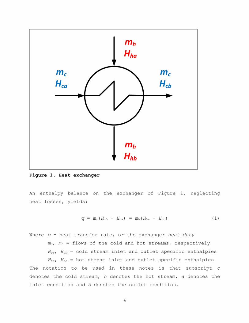
4
mh
Hha
mh
Hhb
mc
Hca
mc
Hcb
Figure 1. Heat exchanger
An enthalpy balance on the exchanger of Figure 1, neglecting
heat losses, yields:
q = mc(Hcb – Hca) = mh(Hha – Hhb) (1)
Where q = heat transfer rate, or the exchanger heat duty
mc, mh = flows of the cold and hot streams, respectively
Hca, Hcb = cold stream inlet and outlet specific enthalpies
Hha, Hhb = hot stream inlet and outlet specific enthalpies
The notation to be used in these notes is that subscript c
denotes the cold stream, h denotes the hot stream, a denotes the
inlet condition and b denotes the outlet condition.
5
Notice that as the hot and cold streams do not mix, the
flow of each stream into the exchanger is the same as the flow
of that stream out of the exchanger.
Equation (1) is really two equations with seven variables,
so its solution requires five specifications. In a design
problem the flow and enthalpies of one stream are specified;
from these the heat duty q can be determined. For the other
stream,
If the inlet and outlet enthalpies are specified, the flow
of the stream can be determined;
If the flow and inlet enthalpy are specified, the outlet
enthalpy can be determined.
2. Calculation of the Enthalpy
The enthalpy of a stream is usually a function of temperature
and of the state of the stream, liquid or vapor. Suppose that a
stream enters an exchanger as a vapor and the vapor is condensed
to its saturation temperature, then completely condensed to a
liquid and finally the liquid is cooled to the exit temperature.
The total change in enthalpy for the stream is then:
Hha – Hhb = cpv(Tha – Tsat) + λsat + cpL(Tsat – Thb) (2)
Where Tha, Tsat, Thb = inlet, saturation, and outlet temperatures
cpv, cpL = specific heats of the vapor and liquid
λsat = latent heat at the saturation temperature
When there on phase change for the stream in an exchanger there
is no latent heat term and there is only one sensible heat term,
either the vapor or the liquid.

6
Example 1. Enthalpy Balance on an Exchanger.
A process produces 55,000 kg/hr of liquid aniline product at a
temperature of 136°C. It is desired to cool the product stream
to 35°C for storage. Cooling water at 30°C is used in the
exchanger to cool the aniline with a maximum allowed rise in
temperature of 10°C. Determine the heat duty of the exchanger
and the flow of cooling water required in liters/min.
Solution.
mh = 55,000 kg/hr
Tha = 136°C
Tca = 30°C
Max rise 10°C
Thb = 35°C
To determine the enthalpy change of the aniline we need its
specific heat. From McCabe, Smith and Harriott, 7th ed., Appendix
15, at the average temperature of (136 + 35)/2 = 85.5°C or
186°F, cpL = 0.55 cal/gm-°C. The heat duty is:
q = (55,000)(0.55)(136 – 35) = 3.06×10⁶ kcal/hr
For the calculation of the required flow of cooling water we
must decide on the outlet temperature of the water. The maximum
temperature rise of 10°C should be used whenever possible
because it results in a smaller flow of water. Using a water
specific heat of 1.0 cal/gm-°C and density of 1 kg/liter:
( )
( )
mh
Hha
mh
Hhb
mc
Hca
mc
Hcb

7
Notice that if we had chosen a smaller water temperature rise,
for example 5°C, it would have required twice the flow of water.
3. Sizing the Exchanger
The purpose of a heat exchanger is to provide enough area
between the hot and the cold streams for heat to be transferred
between them. The area is that of the metal that separates the
two streams, either a tube or a plate. It is very important for
you to visualize in your mind the hot and cold fluids on each
side of the separating surface and the heat flowing through the
surface from the hot fluid to the cold fluid. When you visualize
this you can better understand that the rate at which heat is
transferred through the surface is proportional to the area of
the separating surface and also to the temperature
between the hot stream and the cold stream.
It is critically important that you never confuse the
temperature difference between the hot and cold streams with the
change in the temperature of a stream as it goes through the
exchanger. To facilitate the distinction we will reserve the
term T for the difference in temperature between the hot and
cold streams and never use it for the change in the temperature
of a stream (although this is often done in thermodynamic
courses). It is the temperature difference between the hot and
cold streams that drives the heat from the hot stream to the
cold stream.
The design of an exchanger consists of determining the area
of the exchanger that is necessary to transfer the required heat

8
for the conditions of the exchanger. The basic design equation
is given by:
q = UoAT (3)
where q = heat duty of the exchanger
Uo = over-all heat transfer coefficient
A = heat transfer area
T = temperature difference between the hot and cold
streams
In order to calculate the heat transfer area A from Equation (3)
it is necessary to determine the heat transfer coefficient U and
the temperature difference T. We will look at these next.
Recall that the heat duty q is obtained from the enthalpy
balance on the exchanger, Equation (1).
4. Heat Transfer Coefficient
Consider a hot and a cold stream separated by a plate as in
Figure 2.

9
Th
Twh Twc
Tc
hh
hc
q
xw
Figure 2. Hot and cold streams separated by a plate
Assume that both streams are flowing in turbulent flow past the
plate so that, away from the plate they are perfectly mixed and
the temperature of each stream is uniform, Th for the hot stream
and Tc for the cold stream. Recall from your fluid dynamics
course that, due to viscous forces, the fluid near the wall is
slowed down and flows in a thin laminar film called the viscous
sublayer. The resistance of this film causes the temperature of

10
the hot stream to decrease from Th to the temperature at the wall
on the hot side, Twh. The resistance of the wall causes a further
decrease in temperature from Twh to the wall temperature on the
cold side, Twc. The laminar film on the cold side causes further
decrease in temperature to the bulk temperature of the cold
fluid Tc.
The two fluid films and the plate wall represent three
resistances to the flow of heat from the hot stream to the cold
stream. The resistances of the films depend on the thickness of
the films and the thermal conductivity of the fluids, and the
resistance of the wall is a function of the wall thickness xw and
the thermal conductivity of the wall material.
The thermal conductivity is a property of the material that
indicates how good a conductor of heat it is. Metals have the
highest thermal conductivities and gases the lowest. Appendices
10-13 of McCabe, Smith and Harriott, 7th ed., give the thermal
conductivities of a number of substances, and Appendix 6 has the
thermal conductivity of water.
As the heat transfer rate per unit area through the plate
of Figure 2 is the same through all the resistances, we can
write the following expression:
( ) ( )
( ) ( ) (4)
Where hh, hc = film coefficients on the hot and cold sides
kw = thermal conductivity of the wall
and the temperatures are defined in Figure 2. Now the over-all
temperature difference is the sum of the three individual
temperature differences:
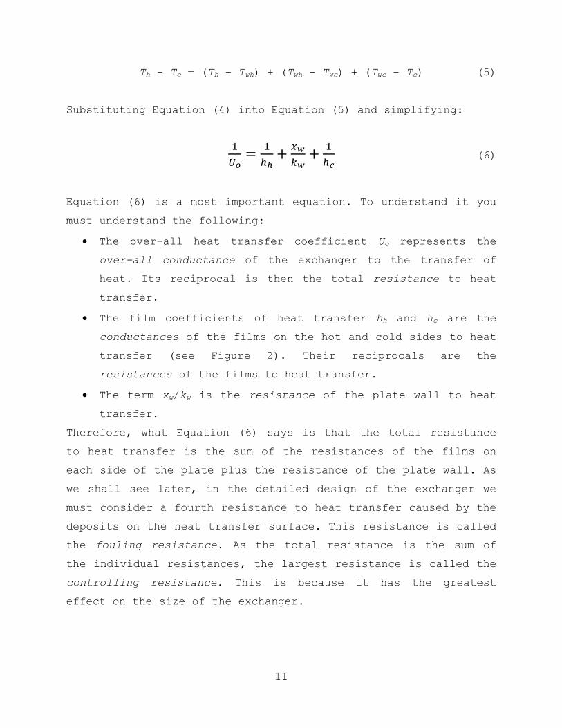
11
Th – Tc = (Th – Twh) + (Twh – Twc) + (Twc – Tc) (5)
Substituting Equation (4) into Equation (5) and simplifying:
(6)
Equation (6) is a most important equation. To understand it you
must understand the following:
The over-all heat transfer coefficient Uo represents the
over-all conductance of the exchanger to the transfer of
heat. Its reciprocal is then the total resistance to heat
transfer.
The film coefficients of heat transfer hh and hc are the
conductances of the films on the hot and cold sides to heat
transfer (see Figure 2). Their reciprocals are the
resistances of the films to heat transfer.
The term xw/kw is the resistance of the plate wall to heat
transfer.
Therefore, what Equation (6) says is that the total resistance
to heat transfer is the sum of the resistances of the films on
each side of the plate plus the resistance of the plate wall. As
we shall see later, in the detailed design of the exchanger we
must consider a fourth resistance to heat transfer caused by the
deposits on the heat transfer surface. This resistance is called
the fouling resistance. As the total resistance is the sum of
the individual resistances, the largest resistance is called the
controlling resistance. This is because it has the greatest
effect on the size of the exchanger.

12
Example 2. Estimate of the Over-all Heat Transfer Coefficient
A process heater uses steam to heat a hydrocarbon liquid in a
plate exchanger made of carbon steel. The film coefficient of
heat transfer for the condensing steam is 20,000 kJ/hr-m2-°C, and
that for heating the hydrocarbon is 3,000 kJ/hr-m2-°C. The
separating wall of the separating plate is 0.200 in. Determine
the over-all heat transfer coefficient for the heater.
Solution. From McCabe, Smith and Harriott, 7th ed., Appendix 10,
the thermal conductivity of 1% carbon steel is about (26 Btu/hr-
ft-°F)(1.055 kJ/Btu)(ft/0.3048 m)(1.8 °F/°C) = 162 kJ/hr-m-°C.
The three resistances are then:
1/hh = 1/20,000 = 5.0×10⁻⁵ hr-m
2-°C/kJ
xw/kw = (0.200 in)(ft/12 in)(0.3048 m/ft)/(162 kJ/hr-m-°C)
= 3.1×10⁻⁵ hr-m
2-°C/kJ
1/hc = 1/3,000 = 33.3×10⁻⁵ hr-m
2-°C/kJ
The total resistance is then:
(5.0 + 3.1 + 33.3)×10-5 = 41.4×10
-5 hr-m
2-°C/kJ
And the over-all heat transfer coefficient is:
Uo = 1/(41.4×10-5) = 2,400 kJ/hr-m
2-°C
Notice that the plate wall resistance is less than 8% of
the total resistance. So, if we were to consider making the
heater wall out of gold, copper, or silver, with thermal
conductivities from 6 to 9 times greater than carbon steel, we
would obtain a minor increase the over-all heat transfer
coefficient at the expense of a much higher exchanger cost.
13
Notice also that the resistance of the condensing steam
side is smaller than that of the hydrocarbon side. In general
condensing steam represents one of the smaller resistances to
heat transfer in an exchanger.
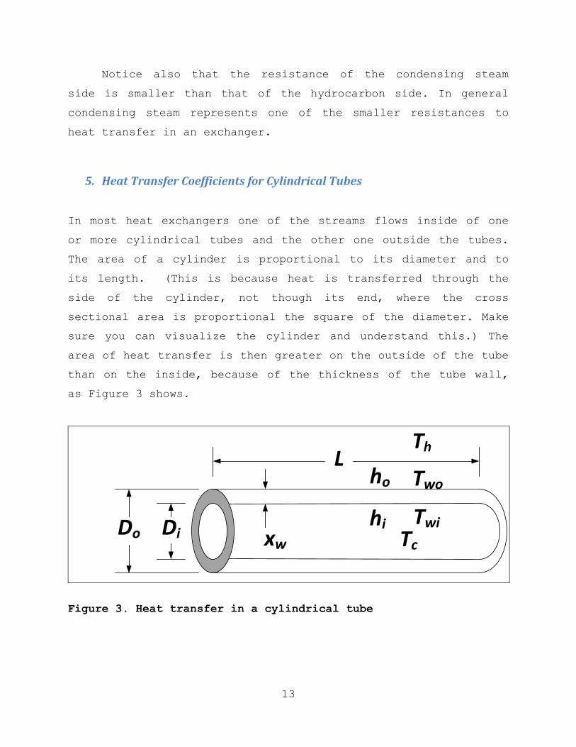
5. Heat Transfer Coefficients for Cylindrical Tubes
In most heat exchangers one of the streams flows inside of one
or more cylindrical tubes and the other one outside the tubes.
The area of a cylinder is proportional to its diameter and to
its length. (This is because heat is transferred through the
side of the cylinder, not though its end, where the cross
sectional area is proportional the square of the diameter. Make
sure you can visualize the cylinder and understand this.) The
area of heat transfer is then greater on the outside of the tube
than on the inside, because of the thickness of the tube wall,
as Figure 3 shows.
L
DiDo
ho
hixw
Th
Two
TwiTc
Figure 3. Heat transfer in a cylindrical tube

14
The side area of a cylinder is DL and, as the figure shows, the
area is larger on the outside of the tube because the diameter
is larger. The heat transfer rate through the tube wall is then
( ) ( )
( ) ( ) (7)
Where ho, hi = film coefficients on the outside and inside
And the other variables are marked on Figure 3. Diameter DM on
the wall resistance term is a mean diameter between the outside
and the inside diameter because the diameter varies through the
wall of the tube. As the area is proportional to the diameter,
it can be shown that the mean diameter is the logarithmic mean
between the inside and the outside diameter:
( ) (8)
As with Equations (5) and (6), the over-all temperature
difference is the sum of the three temperature differences and,
solving from Equation (7) and simplifying, we obtain:
(9)
As Equation (6), Equation (9) says that the total heat transfer
resistance in tube exchangers is the sum of the individual
resistances, the difference being the correction for the inside
and outside diameters.
Notice that the over-all heat transfer coefficient Uo is
based on the outside area of the tube. This is the common
practice because the outside diameter of a pipe or tube is kept
15
the same for the tube of a nominal size when the tube wall
thickness is increased to withstand a higher pressure.
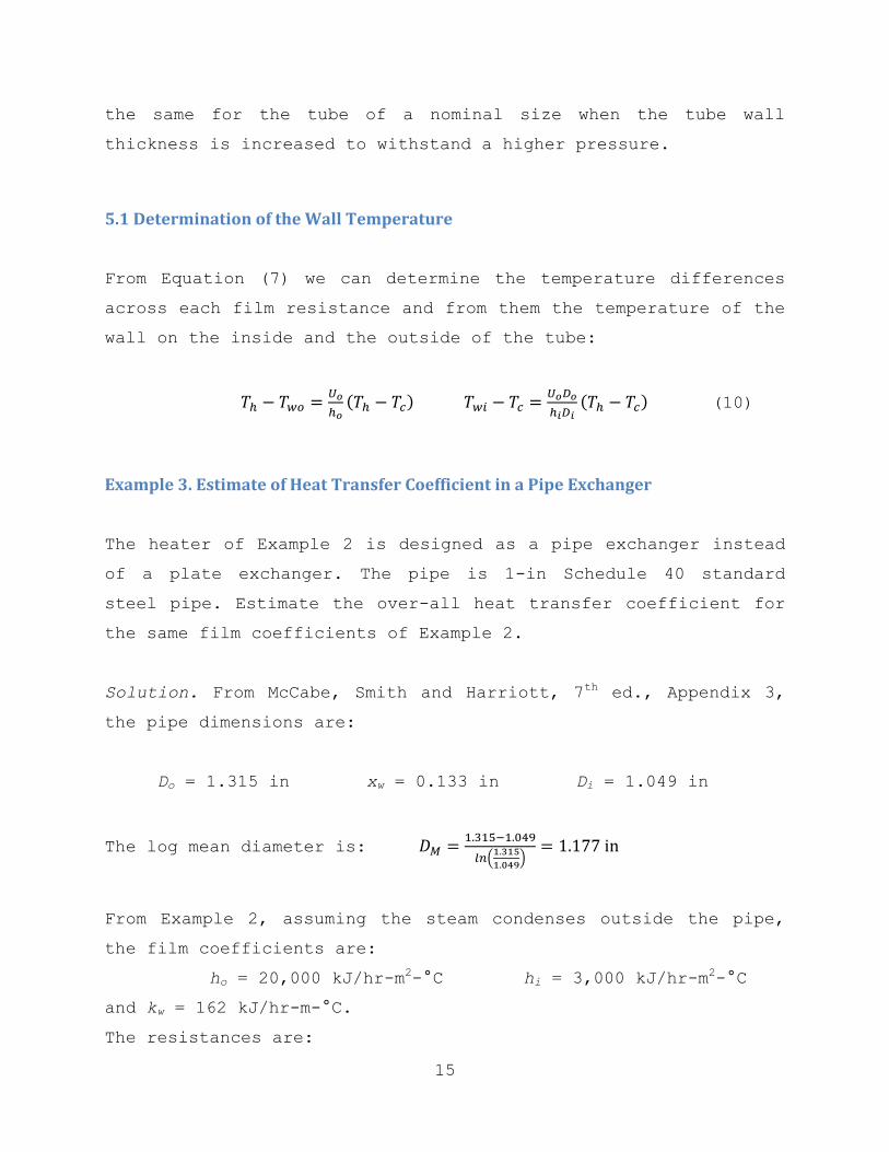
5.1 Determination of the Wall Temperature
From Equation (7) we can determine the temperature differences
across each film resistance and from them the temperature of the
wall on the inside and the outside of the tube:
( )
( ) (10)
Example 3. Estimate of Heat Transfer Coefficient in a Pipe Exchanger
The heater of Example 2 is designed as a pipe exchanger instead
of a plate exchanger. The pipe is 1-in Schedule 40 standard
steel pipe. Estimate the over-all heat transfer coefficient for
the same film coefficients of Example 2.
Solution. From McCabe, Smith and Harriott, 7th ed., Appendix 3,
the pipe dimensions are:
Do = 1.315 in xw = 0.133 in Di = 1.049 in
The log mean diameter is:
(
)
From Example 2, assuming the steam condenses outside the pipe,
the film coefficients are:
ho = 20,000 kJ/hr-m2-°C hi = 3,000 kJ/hr-m
2-°C
and kw = 162 kJ/hr-m-°C.
The resistances are:
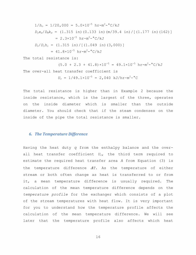
16
1/ho = 1/20,000 = 5.0×10⁻⁵ hr-m
2-°C/kJ
Doxw/DMkw = (1.315 in)(0.133 in)(m/39.4 in)/[(1.177 in)(162)]
= 2.3×10⁻⁵ hr-m
2-°C/kJ
Do/Dihi = (1.315 in)/[(1.049 in)(3,000)]
= 41.8×10⁻⁵ hr-m
2-°C/kJ
The total resistance is:
(5.0 + 2.3 + 41.8)×10-5 = 49.1×10
-5 hr-m
2-°C/kJ
The over-all heat transfer coefficient is
Uo = 1/49.1×10-5 = 2,040 kJ/hr-m
2-°C
The total resistance is higher than in Example 2 because the
inside resistance, which is the largest of the three, operates
on the inside diameter which is smaller than the outside
diameter. You should check that if the steam condenses on the
inside of the pipe the total resistance is smaller.
6. The Temperature Difference
Having the heat duty q from the enthalpy balance and the over-
all heat transfer coefficient Uo, the third term required to
estimate the required heat transfer area A from Equation (3) is
the temperature difference T. As the temperature of either
stream or both often change as heat is transferred to or from
it, a mean temperature difference is usually required. The
calculation of the mean temperature difference depends on the
temperature profile for the exchanger which consists of a plot
of the stream temperatures with heat flow. It is very important
for you to understand how the temperature profile affects the
calculation of the mean temperature difference. We will see
later that the temperature profile also affects which heat

17
exchanger model must be used in a process simulator such as
HySys.
6.1 Linear Temperature Profiles
When the enthalpy of both streams changes by sensible heat, that
is, without phase change or chemical reaction, the temperature
profile of each fluid is approximately linear with heat flow
(because of the variation of the specific heat of the streams
with temperature the profile is slightly curved, but the
curvature can be neglected for design calculations). There are
two ways to arrange the flow of the streams through the heat
exchanger, parallel and countercurrent flow. We will look at
each in turn.
Parallel Flow. In parallel flow the hot and cold streams enter
at one end of the exchanger and exit at the other end, as in
Figure 4.
Tha Thb
Tca
Tcb
Figure 4. Parallel flow in a heat exchanger

18
If the enthalpy change of both streams is due to sensible heat,
the temperature profile for the exchanger of Figure 4 is given
in Figure 5. The figure shows how the temperature of the hot
stream drops linearly as heat is transferred to the cold stream
and similarly the temperature of the cold stream increases
linearly.
It can be shown that the mean temperature difference for
the linear profiles of Figure 5 is given by the logarithmic mean
of the differences at the two ends of the exchanger:
(
) (11)
Where T1 = Tha – Tca and T2 = Thb – Tcb.
Tha
Tca
Tcb
Thb
0 q
T1 T2
Figure 5. Linear temperature profiles for parallel flow

19
Once again we remind you that you are not to confuse the
temperature differences between the hot and cold streams with
the temperature changes of the streams. The temperature changes
in Figures 4 and 5 are Tha - Thb for the hot stream (a drop in
temperature) and Tcb – Tca for the cold stream (a rise in
temperature).
Countercurrent Flow. In countercurrent flow the hot and cold
streams enter the exchanger at opposite ends and flow in
opposite direction to each other, as in Figure 6. The
temperature profile for countercurrent flow is given in Figure
7.
Tha Thb
Tcb
Tca
Figure 6. Countercurrent flow in a heat exchanger

20
Tha
Tca
Tcb
Thb
0 q
T1
T2
Figure 7. Linear temperature profiles for countercurrent flow
As the temperature profiles are linear, the mean temperature
difference is the logarithmic mean given by Equation (11), but
the temperature differences at the two ends are now
T1 = Tha – Tcb and T2 = Thb – Tca
Countercurrent flow is usually preferred to parallel flow
because it is more efficient. Parallel flow is used when it is
necessary to protect the cold stream from the high inlet
temperature of the hot stream because of possible decomposition
of the components.
Example 4. Comparison of Parallel vs. Countercurrent Flow.
Calculate the mean temperature difference for the conditions of
Example 1 for both parallel and countercurrent flow.
21
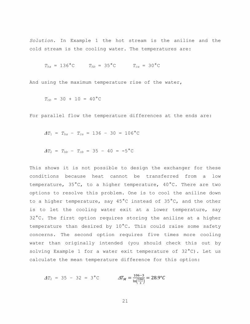
Solution. In Example 1 the hot stream is the aniline and the
cold stream is the cooling water. The temperatures are:
Tha = 136°C Thb = 35°C Tca = 30°C
And using the maximum temperature rise of the water,
Tcb = 30 + 10 = 40°C
For parallel flow the temperature differences at the ends are:
T1 = Tha – Tca = 136 – 30 = 106°C
T2 = Thb – Tcb = 35 – 40 = -5°C
This shows it is not possible to design the exchanger for these
conditions because heat cannot be transferred from a low
temperature, 35°C, to a higher temperature, 40°C. There are two
options to resolve this problem. One is to cool the aniline down
to a higher temperature, say 45°C instead of 35°C, and the other
is to let the cooling water exit at a lower temperature, say
32°C. The first option requires storing the aniline at a higher
temperature than desired by 10°C. This could raise some safety
concerns. The second option requires five times more cooling
water than originally intended (you should check this out by
solving Example 1 for a water exit temperature of 32°C). Let us
calculate the mean temperature difference for this option:
T2 = 35 – 32 = 3°C
(
)

22
A much better option is to run the exchanger in countercurrent
flow. The temperature differences for countercurrent flow are:
T1 = Tha – Tcb = 136 – 40 = 96°C
T2 = Thb – Tca = 35 – 30 = 5°C
And the mean temperature difference is:
(
)
This example has demonstrated why countercurrent flow is more
efficient than parallel flow in heat exchangers. It also shows
that the mean temperature difference is controlled by the
smaller of the two end temperatures. Notice that although the
larger difference is higher for parallel flow (106°C vs. 96°C),
and the smaller difference is only 2°C higher for countercurrent
flow (5°C vs 3°C) the mean temperature difference is higher for
countercurrent flow. The higher the mean temperature difference
the smaller the required exchanger area (see Equation 3).
6.3 Constant Temperature Profile
There are a number of heat exchange situations in which the
temperature of a stream can be assumed constant as the heat is
transferred. These are some of them:
Condensation of a pure component at approximately constant
pressure. Even when there is a small de-superheating of the
vapor or sub-cooling of the condensed liquid, the bulk of
the heat is transferred at the constant saturation
temperature of the component.

23
Vaporization of a pure refrigerant at approximately
constant pressure. The heat of vaporization is transferred
at the constant boiling temperature.
Cooling of an exothermic (or heating of an endothermic)
continuous stirred tank reactor. The heat of reaction is
transferred at the constant temperature of the reactor.
Condensing of vapors from a distillation column. The heat
of condensation is assumed to be transferred at the
constant saturation temperature (bubble-point) of the
distillate.
Generation of vapors in a reboiler of a distillation
column. The heat of vaporization is assumed to be
transferred at the constant saturation temperature (bubble
point) of the bottoms product.
Steam, which is commonly used for heating process stream, falls
in the first category. Figure 7 shows the schematic of a heater
with steam as the heating medium and the corresponding
temperature profile. As the temperature profiles are linear the
mean temperature difference is the logarithmic mean of Equation
(11) with the following temperature differences at the ends:
T1 = Th – Tca and T2 = Th – Tcb

24
mh
Th
mh
Th
mc
Tca
mc
Tcb
Steam
Condensate
Th
Tca
Tcb
Th
0 q
T1
T2
Figure 8. Schematic and temperature profile of a heater
When both the hot and cold stream profiles are constant, as when
steam condenses to heat a distillation reboiler, the men
temperature difference is just the difference between the
constant hot and cold temperatures:
TM = Th – Tc
25
6.4 Nonlinear Temperature Profiles
When one of the stream temperature profiles is not linear, the
logarithmic mean of the two end differences is not the correct
mean temperature difference. This happens in the following
situations:
When there is both sensible heat and latent heat transfer
in one of the streams.
Condensation of a mixture of components where the
condensation temperature varies non-linearly with heat
transferred as the composition of the vapors and their
corresponding saturation temperature (dew point) varies.
To determine the heat transfer area of an exchanger with a
nonlinear profile the exchanger must be divided into sections so
that the temperature profile is linear in each section. The area
of each section is calculated and the sum of the areas of all
the sections becomes the total required area of the exchanger.
Example 5. Sizing an Exchanger with a Nonlinear Temperature Profile
A vapor stream containing 10,000 kg/hr of dichloromethane (DCM)
at 320°C is to be cooled and completely condensed at atmospheric
pressure in a heat exchanger. Cooling water is available at 30°C
with a maximum allowed temperature rise of 10°C. Determine the
mean temperature difference. Compare it with the mean
temperature difference if linear temperature profiles were
assumed.

26
Solution. From Reid, Prausnitz and Sherwood, 3rd ed., Appendix,
the molecular weight of DCM is 84.9, its saturation temperature
at atmospheric pressure (normal boiling point) is 39.9°C, and
latent heat is 6,690 kcal/kmole. From the correlation in
Perry’s, 8th ed., Table 2-156, the specific heat of the vapors at
the average temperature of (320 + 39.9)/2 = 180°C is 63.3
kJ/kmole-°C.
From the enthalpy balance the heat duties for cooling the
vapors (sensible heat) and condensing them (latent heat) are:
Sensible:
( )
Latent:
The water temperature varies from 30°C at the inlet to the
outlet of 30 + 10 = 40°C, using the maximum rise. From the
enthalpy balance, the required flow of water is:
( ) ( )
( )
The temperature of the water at the point the vapors start
condensing is:
Figure 9 shows the temperature profile for the exchanger.

27
Tha
Tca
Tcb Thb
0 qS+qL
T1
T2
qS
Tm
Tcm
Figure 9. Temperature profile for Example 5
The three temperature differences are:
T1 = Tha – Tcb = 320 – 40 = 280°C
Tm = Thb – Tcm = 39.9 – 36.1 = 3.8°C
T2 = Thb – Tca = 39.9 – 30 = 9.9°C
Because of the nonlinear profile we must divide the exchanger
into two sections with linear profiles in each section, the
sensible heat section and the latent heat section. The mean
temperature differences are the logarithmic mean of the to end
temperatures for each section:
Sensible:
(
)
(
)

28
Latent:
(
)
(
)
Had the over-all heat transfer coefficients been specified we
would now calculate the area of each section, but as they are
not, we now calculate the UA product for each section; from
Equation (3):
Sensible: ( )
Latent: ( )
At this point we could estimate a different over-all coefficient
U for each section and calculate the required heat transfer area
A for each section. For now we will calculate the mean
temperature difference for the combined two sections, it is:
Mean temperature difference:
( ) ( ) ( )
( )
Had we assumed a linear temperature profile the mean temperature
difference would have been,
(
)
(
)
If this mean temperature difference were to be used to size the
exchanger it would be undersized by a factor of 8. The reason is
that the logarithmic mean of the two end temperature differences
assumes a linear drop in temperature. You should be able to see
by inspection of Figure 9 that under these conditions the
temperature difference between the hot and cold streams would be

29
much higher than it actually is everywhere in the exchanger,
resulting in a higher mean temperature difference.
6.5 Minimum Approach Temperature
In design engineers must adjust to a number of premises arrived
by the experience of past designs. One such premise is the
establishment of a minimum approach temperature. The approach
temperature is the lowest temperature difference in an
exchanger. When the temperature profiles are linear the approach
temperature occurs at one of the ends of the exchanger, but this
is not the case with nonlinear temperature profiles, as in
Example 5 where the approach temperature takes place at the
point where the vapors start condensing.
As pointed out in Example 4, the logarithmic mean
temperature difference is controlled by the smallest of the two
temperature differences. This means that the mean temperature
difference and therefore the size of the exchanger are highly
dependent on the temperature approach. For this reason it is not
a good idea to specify small approaches.
In this course we will use a minimum temperature
approach of 5°C (10°F).
You may ask, why specify the minimum approach? The answer
is that it depends on how the approach affects the
objectives of the over-all process. For example, in Example
1 the minimum approach is specified because it is safer to
store the aniline at the lowest possible temperature. At
any rate you should be aware that there is usually a
minimum approach when deciding the temperatures in your

30
process design. You must also be aware that the smaller the
approach the larger and more costly the exchanger.
7. Heat Exchanger Simulation
Process simulators such as HySys, Aspen Plus, Process and others
can perform very accurate enthalpy and equilibrium calculations
based on extensive data banks of component physical properties.
This section presents some guidelines on how to simulate heat
exchangers. It is important to realize that the simulator is
just a tool; you, the engineer, must still do the thinking.
Inlet Streams. The flow, composition, and temperature or other
enthalpy parameter (e.g., fraction vaporized, saturated liquid)
must either be defined or be outlet streams from other
operations such as mixers, reactors or distillation columns.
Pressure Drop. The pressure drop required for the stream to flow
through the exchanger must be specified. The following are
common design premises for the pressure drop:
70 kPa (10 psi) for all liquid streams being heated or
cooled.
35 kPa (5 psi) for vapor or partially vaporized streams.
Negligible pressure drop when the stream is totally
condensed or totally vaporized. For example, condensers and
reboilers in distillation columns, condensing steam,
vaporizing refrigerant.
Understand that in open (flowing) systems the pressure must
always drop when the stream flows through the exchanger, even
when the stream is being heated.

31
7.1 Simple Exchanger Models
Simulators offer a simple exchanger model (called “Heater” or
“Cooler” in HySys and “One-sided Exchanger” in Aspen Plus).
These models compute only the heat duty of the exchanger and are
used when there is only one process stream and the other stream
is a utility such as cooling water, steam or refrigerant.
Furnaces are also simulated with these models.
The only specification required is either the temperature
or the enthalpy condition of the exit stream. The enthalpy
condition is either the vapor fraction, saturated liquid (vapor
fraction = 0) or saturated vapor (vapor fraction = 1). When the
enthalpy condition is specified the simulator calculates the
temperature and the enthalpy of the exit stream and that is what
is needed to calculate the heat duty of the exchanger. The exit
temperature must only be specified when the exit stream is not
saturated, that is, either a subcooled liquid or a superheated
vapor.
The simple exchanger model may be used
when it is not necessary to size the exchanger from the
results of the simulation, or
when the temperature profile of the process stream is
linear (no phase change). This is because the area of the
exchanger can then be calculated from the logarithmic mean
of the two end temperature differences.
7.2 Rigorous Heat Exchanger Models
Simulators also offer a rigorous heat exchanger model that
requires the specification of both streams, even when one of
them is a utility. The rigorous model must be used when

32
the exchanger is a cross-exchanger between two process
stream, or
the temperature profile of the process stream is nonlinear,
as in Example 5.
In the second case the utility stream, steam, cooling water or
refrigerant, must be defined.
The specification of the rigorous model is either the
outlet temperature or vapor fraction of one of the two process
streams in a cross-exchanger. When one stream is a utility its
outlet temperature or vapor fraction should be specified; the
simulator then calculates the required utility stream flow. Do
these instructions make sense to you? They should if you
understand the enthalpy balance, Equation (1), and realize that
is how the simulator calculates the heat duty.
“Weighted” Exchanger. When the temperature profile is nonlinear
the “weighted” option of the rigorous heat exchanger model must
be specified if the results of the simulation are to be used to
size the exchanger. The other option is the “End Point” which
calculates the mean temperature difference as the logarithmic
mean of the two end differences. (Even the simulator can
calculate the incorrect result if you don’t specify it
correctly.) The weighted option divides the exchanger into
sections of linear temperature profiles, as in Example 5, as
many sections as you specify, but normally five sections by
default. The result of the model is then the total UA for the
exchanger which can be used to determine the area A from the
over-all heat transfer coefficient U.
8. Film Coefficients of Heat Transfer

33
We have seen earlier in these notes that the over-all heat
transfer coefficient Uo is a function of the film coefficients on
each side of the wall separating the hot and cold fluids, and of
the resistance of the wall (Equations 6 and 9). This section
presents the correlations to estimate the film coefficients for
different flow situations. One thing to keep in mind is that the
formulas we use are correlations of experimental data and not
fundamental equations. Their accuracy is of the order of 20%.
8.1 Turbulent Flow inside Conduits without Phase Change
Turbulent flow is more efficient for heat transfer than laminar
flow because the bulk of the fluid away from the wall is kept at
a uniform temperature by the mixing eddies so that the
resistance to heat transfer is limited to a narrow film around
the wall (see Figure 2). A popular correlation to estimate the
film coefficient of heat transfer for turbulent flow without
phase change is the Sieder-Tate equation:
(
) (
) (
)
(12)
Where h = the film coefficient of heat transfer
De = the equivalent diameter (to be defined shortly)
k = the thermal conductivity of the fluid
= the density of the fluid
u = the average velocity of the fluid
= the viscosity of the fluid
cp = the specific heat of the fluid
w = the viscosity of the fluid at the wall temperature

34
The fluid properties are evaluated at the arithmetic mean of the
inlet and outlet temperatures of the fluid, and the wall
temperature is determined from Equation (10) using the
arithmetic mean temperatures of the cold and hot fluids.
Equation (12) involves four dimensionless numbers:
hDe/k = the Nusselt number
De u/ = the Reynolds number
cp /k = the Prandtl number
/ w = the viscosity at the wall correction.
The equation is only valid for Reynolds number greater than
6,000 and does not apply to molten metals.
The viscosity at the wall correction term ( / w)0.14
takes
into consideration that the viscosity near the wall is what
controls the thickness of the laminar sub-layer and therefore
the resistance of the film. The term is greater than unity for
the cold liquid and less than unity for the hot liquid because
the viscosity of liquids decreases with temperature. The reverse
is true for gases. As the exponent is small, the correction may
be neglected for fluids with low viscosity such as water.
8.2 The Equivalent Diameter
The equivalent diameter De in the Nusselt and Reynolds numbers is
defined as:
(13)
35
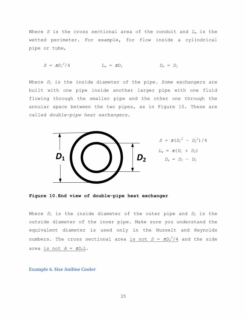
Where S is the cross sectional area of the conduit and Lw is the
wetted perimeter. For example, for flow inside a cylindrical
pipe or tube,
S = Di2/4 Lw = Di De = Di
Where Di is the inside diameter of the pipe. Some exchangers are
built with one pipe inside another larger pipe with one fluid
flowing through the smaller pipe and the other one through the
annular space between the two pipes, as in Figure 10. These are
called double-pipe heat exchangers.
S = (D12 – D2
2)/4
Lw = (D1 + D2)
De = D1 – D2
Figure 10.End view of double-pipe heat exchanger
Where D1 is the inside diameter of the outer pipe and D2 is the
outside diameter of the inner pipe. Make sure you understand the
equivalent diameter is used only in the Nusselt and Reynolds
numbers. The cross sectional area is not S = De2/4 and the side
area is not A = DeL.
Example 6. Size Aniline Cooler
D1 D2

36
Design a double-pipe heat exchanger for the aniline cooler of
Example 1. Use a 1-in Schedule 40 steel pipe inside a 2-in
Schedule 40 pipe.
Solution. Select countercurrent flow with the aniline flowing
through the inner pipe and the water through the annulus between
the pipes.
mh
ThaThb
Tcb
mc Tca
Figure 11. Double pipe heat exchanger for Example 6
From Example 1:
Aniline: mh = 55,000 kg/hr Tha = 136°C Thb = 35°C
Water: mc = 306,000 kg/hr Tca = 30°C Tcb = 40°C
Heat duty: q = (3.06×10⁶ kcal/hr)(4.187 kJ/kcal) = 12.8×10
6 kJ/hr
And, from Example 4: TM = 30.8°C
From McCabe, Smith and Harriott, 6th ed. Appendix 3:
Inner pipe, 1-in Sch. 40:
Di = 1.049 in, Do = 1.315 in, Sh = 0.00600 ft2, xw = 0.133 in
Outer pipe, 2-in Sch. 40: Doi = 2.067 in
For the annulus:
Equivalent diameter: 2.067 – 1.315 = 0.752 in

37
Cross sectional area: (2.0672 – 1.3152)/4 = 2.00 in2 = 1.29×10⁻³m2
Properties of aniline, from McCabe, Smith and Harriott, 7th ed.:
Average temperature: (136 + 35)/2 = 85.5°C (186°F)
Viscosity: 0.91 cP = 3.28 kg/m-hr (Appendix 9)
Thermal conductivity: 0.100 Btu/ft-hr-°F =
0.622 kJ/m-hr-°C (Appendix 13)
Specific heat: 0.55 kcal/kg-°C = 2.30 kJ/kg-°C (Appendix 15)
Specific gravity: 1.022 (Perry’s, Table 2-2)
Prandtl number:
(
)
Properties of water, from McCabe, Smith & Harriott, Appendix 6:
Average temperature: (30 + 40)/2 = 35°C (95°F)
Viscosity: 0.723 cP = 2.60 kg/m-hr
Thermal conductivity: 0.360 Btu/ft-hr-°F = 2.24 kJ/m-hr-°C
Specific heat: 1.0 kcal/kg-°C = 4.187 kJ/kg-°C
Specific gravity: 1.0
Prandtl number:
(
)
Calculate the average velocities:
Aniline:
(
)
This velocity is too high. We must use several exchangers in
parallel to bring the velocity down. Let us use 50 exchangers in
parallel: ui = 26.8/50 = 0.536 m/s.
Water velocity:
Next calculate the Reynolds numbers:
Aniline:

38
Water:
The flow is definitely turbulent, so we can use the Sieder-Tate
correlation. The film coefficients are then, neglecting the
viscosity at the wall correction:
Aniline:
( ) ( )
Water:
( ) ( )
For the wall resistance, the thermal conductivity of steel is 26
Btu/ft-hr-°F (McCabe, Smith & Harriott, 7th ed., Appendix 10). So
the resistances are:
Aniline: Do/Dihi = (1.315/1.049)/2,850 = 4.4×10⁻⁴ hr-m
2-°C/kJ
Water: 1/ho = 1/ 19,600 = 0.5×10⁻⁴ hr-m
2-°C/kJ
Wall:
( )
(
)
The aniline resistance is controlling. Over-all heat transfer
coefficient:
Uo = 1/(4.4 + 0.2 + 0.5)×10-4 = 1,960 kJ/hr-m
2-°C
The total required heat transfer area is:
( )( ) (2,300 ft
2)
Length of each exchanger: Ao = 50DoL
( ) (132 ft)

39
So, fifty exchangers each longer than 40 m are required.
Obviously this will not be a good design. A shell-and-tube heat
exchanger should be used. These will be introduced shortly.
8.3 Laminar Flow
Although laminar flow is not as efficient as turbulent flow to
transfer heat, sometimes it cannot be avoided when the fluid is
very viscous. The following correlation can be used when the
Reynolds number is less than 6,000:
(
) (
)
(14)
Where m = the mass flow
Nt = the number of tubes in parallel
L = the tube length
Notice that m/Nt is the mass flow per tube. The rest of the terms
were defined with Equation (12).
8.4 Condensing Vapors on Vertical Tubes
The model for vapors condensing on vertical tubes is that the
resistance to heat transfer is presented by a film of condensate
flowing down the tube. The thickness of this film increases down
the tube. The flow may be laminar or turbulent. The correlation
uses the following form of the Reynolds number:
(15)

40
Where Nt is the number of tubes. When this Reynolds number is
less than 2,100, the following correlation applies:
(
)
(16)
And when the Reynolds number is greater than 2,100:
(
)
(17)
The subscript f on the physical properties indicates that they
must be evaluated at the film temperature, defined by
Tf = Th – 0.75(Th – Twh) (18)
As condensing steam is commonly used for heating process streams
in industry, the group on the right of Equations (16) and (17)
and later on Equation (20), is given as a function of
temperature for water in Appendix 6 of McCabe, Smith and
Harrriott, 7th edition.
8.5 Condensing Vapors on Horizontal Tubes
The model for condensation on horizontal tubes is that the
condensate from each tube drains to the tubes below so that the
film thickness is larger on the lower tubes. The correlation
uses the following form of the Reynolds number:

41
(19)
Where Nt is the number of tubes. When this Reynolds number is
less than 2,100, the following correlation applies:
(
)
(20)
Where Nstack is the number of tubes stacked in a vertical row.
8.6 Boiling Liquids
There are no generally accepted correlations for estimating the
film coefficients in boiling liquids. Experimental determined
over-all coefficients are used in the design of evaporators and
reboilers.
One important characteristic of boiling liquids is that
there are several regimes of boiling that depend on the
temperature difference between the heating surface and the
boiling liquid. The regimes are,
Natural Convection. At low temperature differences (T <
5°C) heat is transferred at very low rates by natural
convection.
Nucleate Boiling. As the temperature difference increases
(5°C < T < 25°C) vapor bubbles start forming and as they
rise to the surface create forceful mixing of the liquid
promoting efficient heat transfer.

42
Film Boiling. As the temperature difference continues to
increase (T > 25°C) the bubbles form so rapidly that a
film of vapor covers the heating surface creating a higher
resistance to heat transfer. This is undesirable.
You may observe these regimes by boiling a pot of water on a
stove and observing the boiling process, at least the first two
regimes. The generation of the vapor bubbles should let you
appreciate why heat transfer is more efficient in the nucleate
boiling regime.
The most efficient heat transfer is obtained around the
upper range of the nucleate boiling regime, 25°C. Study of
Figures 13.4 and 13.5 of McCabe, Smith and Harriott, 7th ed. and
the description in the text will help you understand the basic
concepts of designing evaporators and reboilers.
9. Shell and Tube Heat Exchangers
Shell and tube heat exchangers consist of a bundle of tubes
enclosed in a cylindrical shell. One stream flows through the
tubes and the other one flows through the shell outside the
tubes. These exchangers provide a high density of heat transfer
area, up to about 500 m2 (5,000 ft
2) in a single shell. The
results of Example 6 showed us that it is impractical to build a
large double-pipe heat exchanger. The same can be said of coils
and jackets to cool and heat reactors and other vessels, and of
plate heat exchangers. When large areas are required to transfer
heat, shell and tube heat exchangers are normally used.
Shell and tube exchangers can have a single tube pass, as
in Figure 12, and multi-pass exchangers, as in Figure 13. When a
multi-pass exchanger is used the number of tube passes is always
and even number.

43
mT
TTa
mS
TSa
TTb
TSb
BaffleTube
P
Shell
Figure 12. Single tube-pass shell and tube exchanger
In the figures the subscript T refers to the stream flowing
inside the tubes and S is for the stream flowing in the shell.
Either stream can be the hot or the cold stream.
The baffles on the shell side are intended to force the
shell side streams to flow perpendicular to the tubes to promote
higher turbulence and also to increase the velocity of the
stream. The turbulence and the higher velocity increase the film
coefficient on the shell side. One design parameter is the
baffle pitch P which is adjusted by selecting the number of
baffles and determines the velocity of the shell side stream.
Baffles are not necessary when the shell stream is either a
condensing vapor or a vaporizing liquid.
The disadvantage of the single tube pass exchanger is that
the shell cannot be removed to clean the outside of the tubes
when solids deposit on them. Inspection of Figure 13 shows that
the shell in a multi-pass exchanger can be removed to clean the
tubes, as long the number of tube passes is even. (The baffles
are not attached to the shell.)
44
mT
TTa
mS
TSa
TTbTSb
BaffleTube
P
Shell
Figure 13. Multiple tube-pass shell and tube exchanger
Notice that in the multi-pass exchanger the shell stream
should enter at the end of the exchanger where the tube stream
enters and leaves. Otherwise there may be a temperature cross,
that is, a portion of the exchanger where the cold stream
temperature is higher than the hot stream temperature.
Surprisingly enough, in theory, the mean temperature difference
is the same independent of the entrance end of the shell stream.
In other words, in theory it does not matter if there is a
temperature cross in a multi-pass exchanger, but it should be
avoided in practice anyway.
The heat transfer area of a shell and tube exchanger based
on the outside area of the tubes is:
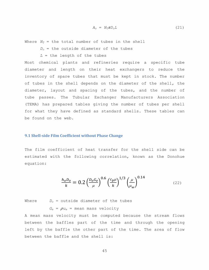
45
Ao = NTDoL (21)
Where NT = the total number of tubes in the shell
Do = the outside diameter of the tubes
L = the length of the tubes
Most chemical plants and refineries require a specific tube
diameter and length on their heat exchangers to reduce the
inventory of spare tubes that must be kept in stock. The number
of tubes in the shell depends on the diameter of the shell, the
diameter, layout and spacing of the tubes, and the number of
tube passes. The Tubular Exchanger Manufacturers Association
(TEMA) has prepared tables giving the number of tubes per shell
for what they have defined as standard shells. These tables can
be found on the web.
9.1 Shell-side Film Coefficient without Phase Change
The film coefficient of heat transfer for the shell side can be
estimated with the following correlation, known as the Donohue
equation:
(
) (
) (
)
(22)
Where Do = outside diameter of the tubes
Ge = ue = mean mass velocity
A mean mass velocity must be computed because the stream flows
between the baffles part of the time and through the opening
left by the baffle the other part of the time. The area of flow
between the baffle and the shell is:

46
(
) (23)
Where Sb = area of flow between the baffle a the shell
Ds = inside diameter of the shell
When the baffle length is ¾ of the shell diameter, fb = 0.196.
The area of flow between baffles is determined at the center of
the shell:
(
) (24)
Where P = the baffle pitch or spacing between the baffles
pT = tube pitch or distance between the tube centers.
The mean mass velocity is then determined with the geometric
mean of the two flow areas:
√ (25)
Where mS is the mass flow of the shell stream.
From the correlation of Equation (22) the shell-side film
coefficient proportional to the mass velocity to the 0.6 power.
When the shell-side coefficient is too small and the controlling
resistance, it can be increased by increasing the number of
baffles thus reducing the area of flow between the baffles and
increasing the mass velocity. However, when the velocity is
increased the pressure drop through the exchanger also increases
imposing a limit on the number of baffles. The pressure drop is
proportional to the square of the velocity and to the number of

47
baffles. To keep the pressure drop reasonable the velocity
should not exceed 2 m/s (7 ft/s) for liquids or 20 m/s (70 ft/s)
for vapors.
9.2 Selecting the Number of Tube Passes
In a multi-pass exchanger the number of passes can be selected
as an even number (2,4,6…). The velocity inside the tubes is
determined by the number of tubes per pass:
(26)
Where GT = mass velocity in the tubes
uT = average velocity in the tubes
mT = mass flow of the stream flowing in the tubes
Np = number of tubes per pass
Di = inside diameter of the tubes.
For the film coefficients inside the tubes the Sieder-Tate
correlation, Equation (12), applies. The film coefficient is
proportional to the velocity raised to the 0.8 power. So, if the
inside film coefficient is small and the controlling resistance,
it can be increased by increasing the number of tube passes
which in turn increases the velocity. So going from 2 to four
passes the velocity doubles and the inside film coefficient is
increased by a factor of 20.8 = 1.74 for a 74% increase.
As with the number of baffles on the shell side, increasing
the number of tube passes increases the pressure drop through
the tubes, but unlike the baffles the number of tube passes can
take only even numbers. The pressure drop through the tubes is

48
proportional to the velocity squared and to the number of tube
passes so, if the number of tube passes is doubled, the pressure
drop increases by a factor of 22×2 = 8. So, for example, if the
initial pressure drop is small such as 1 psi (7 kPa), increasing
the number of passes from 2 to 4 increases the pressure drop to
8(1) = 8 psi (56 kPa) which is acceptable, but increasing the
number of passes to 6 increases the pressure drop to 3×32(1) = 27
psi (186 kPa) which is excessive. Recall that the desired
pressure drops in exchangers are typically from 5 to 10 psi (35
to 70 kPa). To maintain reasonable pressure drops the velocity
should not exceed 2 m/s (7ft/s) for liquids or 20 m/s (70 ft/s)
for vapors.
9.3 Correction of Mean Temperature Difference for Multi-pass Exchanger
The flow in a multi-pass exchanger is not parallel or
countercurrent, but a combination of the two. As Figure 13
shows, the stream in the tubes moves first in parallel with the
shell-side stream and then in countercurrent. If the temperature
of one of the two streams is constant, the mixed flow does not
affect the mean temperature difference which is the logarithmic
mean of the end differences. Figure 14 shows the profile as a
plot of temperature versus the position in the exchanger for two
tube passes. (The profiles versus position are not linear while
the profiles of temperature versus heat transferred are linear.)

49
20
25
30
35
40
45
50
55
Te
mp
er
at
ur
e
Exchanger position
Shell stream Tube stream Tube stream return
T2
T1
Figure 14. Temperature vs. position for two-tube pass exchanger
The mean temperature difference for a multi-pass exchanger is
determined by using a correction factor to the logarithmic mean
temperature difference for the counter-current exchanger:
(
) (27)
Where the correction factor FG for a single shell pass and any
even number of tube passes is:
(√
) (
)
[
√
√
]
(28)

50
Where
The correction factor is the same whether the cold or the hot
stream flow through the tubes. A plot of Equation (28) can be
found in McCabe, Smith and Harriott, 7th ed., Figure 15.6(a).
9.4 Correction of Mean Temperature Difference for Two Shell Passes
When the correction factor FG for one shell pass is too low (<
0.9), two shell passes are used. Two shell passes usually
consists of two identical shells with multiple tube passes, with
the total number of tube passes being a multiple of 4 (4, 8,
12,…). The two shells must be arranged in countercurrent, as in
Figure 15. Although two shells are used, the exchanger is sized
(and simulated) as a single exchanger.
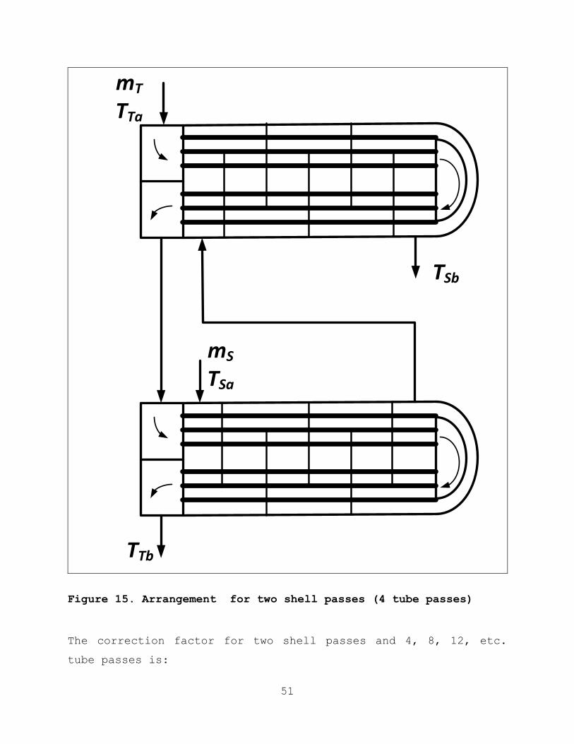
51
mT
TTa
TSb
mS
TSa
TTb
Figure 15. Arrangement for two shell passes (4 tube passes)
The correction factor for two shell passes and 4, 8, 12, etc.
tube passes is:

52
(√
( )) (
)
[
√( )( )
√
√( )( )
√
]
(29)
The factor is used in Equation (27) to compute the mean
temperature difference with two shells. Keep in mind that the
two shells must be identical. A plot of Equation (29) can be
found in McCabe, Smith and Harriott, 7th ed., Figure 15.6(b).
The following applies to Equations (28) and (29):
If the temperature of one of the two streams is constant
(condensing pure vapor or boiling liquid) FG = 1.0.
It does not matter which stream, the hot or the cold, flows
in the tubes.
It does not matter in which direction the shell fluid
flows.
9.5 Cross Flow
In some exchangers, typically air-cooled exchangers, the flow of
the two streams is perpendicular to each other. This is called
cross flow. For the correction factor of the mean temperature
difference in cross flow see McCabe, Smith and Harriott, 7th ed.,
Figure 15.7. We will not discuss the design of air-cooled
exchangers in these notes.
10. Quick Design of Heat Exchangers

53
In situations such as the preliminary design of a process there
are many heat exchangers to design. It is then desirable to have
a quick design approach that saves the time of having to do the
detailed design of each heat exchanger. The quick design
procedure consists of calculating the heat duty and mean
temperature difference and estimate the heat transfer area using
typical over-all coefficients for the type of exchanger under
consideration. The detailed design of each exchanger is then
done at a later stage of the design of the process.
To estimate the heat transfer coefficient, resistances for
typical heat transfer situations are used, such as those shown
in Table 1.
Table 1. Typical Film Resistances for Quick Design
In hr-m2-°C/kJ (multiply by 20 to get hr-ft
2-°F/Btu)
Fluid No phase
change
Boiling
liquid
Condensing
vapor
Fixed gases (N2, O2, etc.) 2.2×10⁻³
Light hydrocarbon gases 1.7×10⁻³
Aromatic liquids 0.35×10⁻³ 0.15×10
-3 0.35×10
-3
Light hydrocarbon liquids 0.2×10⁻³ 0.15×10
-3 0.2×10
-3
Chlorinated hydrocarbons 0.2×10⁻³ 0.15×10
-3 0.2×10
-3
Steam 2.2×10⁻³ 0.05×10
-3
Boiler water 0.35×10⁻³ 0.15×10
-3
Cooling tower water 0.35×10⁻³
At this level of detail the wall and dirt resistances may be
neglected and the over-all coefficient estimated by

54
(30)
Where rh and rc are the resistances of the hot and cold streams
from Table 1.
Example 7. Estimate the area required for the aniline cooler of Example 1
From the results of Example 1,
Heat duty: q = (3.06×10⁶ kcal/hr)(4.187 kJ/kcal) = 12.8×10
6 kJ/hr
From the results of Example 3, for countercurrent flow,
Mean temperature difference: TM = 30.8°C
Solution. From Table 1 the resistances are:
Cooling aromatic liquids: rh = 0.35×10⁻³ hr-m
2-°C
Cooling tower water: rh = 0.35×10⁻³ hr-m
2-°C
Over-all coefficient: Uo = 1/(0.35+0.35)×10-3 = 1,430 kJ/hr-m
2-°C
Heat transfer area: Ao = (12.8×10⁶)/[(30.8)(1,430)] = 290 m
2
Or 3,100 ft2. Compare with 212 m
2 for the detailed design of a
double-pipe heat exchanger in Example 6. The disagreement is
within the expected accuracy of the values in Table 1. The
purpose of the table is just to obtain an approximate exchanger
size with a quick calculation. Compare also the complexity of
the calculations of Example 6 with those in this example.

55
11. Quick Estimate of Exchanger Cost
Correlations have been developed to estimate the cost of an
exchanger based on the heat transfer area. As would be expected,
the accuracy of these correlations is of the order of 30%. The
following correlations are adapted from the ones on Douglas,
Conceptual Design of Chemical Processes, McGraw-Hill, 1989,
Appendix E.
(
) (
)
( ) (31)
Where ICexch = the installed cost of the exchanger
M&S = the Marshal and Swift equipment inflation index
Ao = the heat transfer area in m2
And Fc is a cost factor which is 1.0 for a floating head
exchanger in carbon steel with a design pressure of less than
1000 kPa gage (150 psig).
The correlation of Equation (31) is valid for exchangers of
up to 500 m2 (5,000 ft
2). When the area is larger than the
correlation limit the cost is best estimated by assuming more
than one exchanger all with the same area less than the limit,
e.g., for a 900 m2 exchanger assume three exchangers of 300 m
2
each.
For other exchanger types, design pressures and materials
of construction, the cost factor is
Fc = Fm(Fd + Fp) (32)
Most exchangers are of the floating head type for which Fd =
1.00, U-tube type, Fd = 0.85, or fixed head (one tube pass), Fd =

56
0.80. The factors for material of construction and the design
pressure are:
Cost factors for material of construction, shell/tube
Material CS/CS CS/Brass CS/MO CS/SS SS/SS CS/Monel Monel/Monel CS/Ti Ti/Ti
Fm 1.00 1.30 2.15 2.81 3.75 3.10 4.25 8.95 13.05
CS = Carbon Steel; SS = Stainless Steel; Ti = Titanium.
Cost factors for design pressures up to
kPa gage 1030 2070 2760 5510 6900
psig 150 300 400 800 1000
Fp 0.00 0.10 0.25 0.52 0.55
Example 8. Estimate the cost of the heat exchanger of Example 1
From the results of Example 7, Ao = 290 m2.
Solution. Assuming a floating head exchanger in carbon steel and
low pressure, from Equation (31), using a current inflation
index of 2,000:
Installed cost:
( ) ( )
With the area from Example 6, 212 m2, the cost would be $370×10
3,
which for preliminary design purposes is the same (within 20%).
12. Detailed Design of a Heat Exchanger
The detailed design of a shell and tube exchangers goes beyond
the estimate of the heat transfer area Ao. It involves the
determination of
The shell diameter

57
The number of tubes
The number of tube passes
The number of baffles
A more accurate estimation of the over-all heat transfer
coefficient Uo based on the velocities and properties of the
hot and cold streams.
Before discussing the design procedure we must present the
concept of the fouling resistance.
12.1 Fouling Resistance
When an exchanger is new or has just been cleaned there is no
dirt deposited on its heat transfer surfaces and the over-all
coefficient is the highest it can be for that exchanger. This
coefficient is called the clean coefficient. As the exchanger is
put in service dirt deposits on its surfaces and the coefficient
decreases reducing the capacity of the exchanger to transfer
heat. Eventually the coefficient is so low that the exchanger is
said to be “fouled up.” It must then be taken out of service and
cleaned. If the exchanger is not sufficiently over-sized the
period between cleanings is short requiring frequent shut downs
for cleaning. This is costly and inconvenient. Therefore
exchangers must be over-sized by having the heat transfer area
larger than that required by the clean coefficient. The
oversizing is done by allowing for the resistance of the dirt,
called the fouling allowance.
The fouling allowance is calculated as a resistance which
is the difference between the resistance of the design
coefficient and the clean coefficient:

58
(33)
Where ff = fouling allowance
UoD = design over-all coefficient
UoC = clean over-all coefficient
A properly designed exchanger must allow sufficient fouling
resistance for the service of the exchanger so that the period
between cleanings is long, of the order of several months to a
year. For most services the fouling allowance should be of the
order of 0.1×10⁻³ hr-m
2-°C/kJ (0.002 hr-ft
2-°F/Btu).
12.2 Detailed Design Procedure
The following is the procedure for the detailed design of a
shell and tube heat exchanger:
1. Calculate the heat duty q and exit temperature or flow from
the enthalpy balance.
2. Calculate the mean temperature difference TM. Note: If one
shell pass does not work must use two shell passes.
3. Estimate the over-all heat transfer coefficient Uo from
typical resistances such as those in Table 1.
4. Calculate the estimated heat transfer area, Ao = q/UoTM.
5. Determine the number of tubes NT using the company-specified
tube diameter and length, NT = Ao/DoL.
6. Select the number of tube passes Np to obtain a reasonable
velocity inside the tubes, ui = miNp/(NT iDi2/4).

59
7. Select a TEMA standard shell diameter containing a number
of tubes NT slightly higher than the one calculated in step
5. Correct the tube side velocity from step 6.
8. Select the number of baffles Nb to produce a reasonable
velocity of the shell stream, uo = mo/[PDs o(1-Do/pT)], P =
L/(Nb + 1). Note: The minimum baffle pitch P is Ds/5 or 2
in, whichever is larger.
9. Calculate the design coefficient, UoD = q/(NTDoLTM).
10. Calculate the clean coefficient UoC from the film
coefficients and the resistance of the wall and check that
the allowed fouling resistance is large enough.
11. If the allowed fouling resistance is too small or
negative, select a larger shell diameter and repeat the
calculations from step 7. Otherwise the detailed design of
the exchanger is complete.
This procedure is demonstrated in the following example.
Example 9. Detailed design of aniline cooler of Example 1
The client requires the exchanger tubes to be 5/8-in OD on
15/16-in square pitch and 20 ft long.
Solution. Have the aniline flow through the tubes and the water
through the shell. From Example 1:
mh = 55,000 kg/hr Tha = 136°C Tcb = 35°C
mc = 306,000 kg/hr Tca = 30°C Tcb = 40°C
1. Enthalpy balance (from Example 1):
q = 12.8×10⁶ kJ/hr

60
2. Mean temperature difference, withy multi-pass correction.
The one shell correction factor tells us that two shells
are needed. So, the correction factor for two shells is
Z = (136 – 35)/(40 – 30) = 10.1
H = (40 – 30)/(136 – 30) = 0.0943
√
( ) (
( )( ))
(
√( )[ ( )( )] √
√( )[ ( )( )] √
)
( ) ( )
(
)
3. Estimate the over-all heat transfer coefficient. From Table
1, the estimated resistances are:
rh = 0.35×10⁻³ hr-m
2-°C/kJ (aromatic liquid)
rc = 0.35×10⁻³ hr-m
2-°C/kJ (cooling tower water)
Uo = 1/(0.035 + 0.035)×10-3 = 1,430 kJ/hr-m
2-°C
4. Estimate the heat transfer area.
Ao = (12.8×10⁶)/[(1,430)(29.2)] = 307 m
2
5. Determine the number of tubes. For 5/8-in OD 14 BWG tubes,
20 ft long, from McCabe, Smith and Harriott, 7th ed.,
Appendix 4:
Do = 5/8 = 0.625 in Di = 0.459 in
Si = 0.00115 ft2 = 1.07×10
-4 m
2 xw = 0.083 in
And L = 20 ft = 6.10 m
( )( )
6. Select the number of tube passes for a reasonable tube-side
velocity. The density of aniline, from Perry’s Table 2.2,
is 1,022 kg/m3.
For 4 tube passes: ( )
( )( )( )
This velocity is too low, so use 8 tube passes, for a
velocity of 1.10 m/s.

61
7. Select a TEMA standard shell with the number of tubes. From
http://www.globalspec.com/reference/38650/203279/Appendix-
C-Tube-Count-Tables, for 5/8-in OD tubes on 13/16-in square
pitch:
Ds = 23.25 in = 0.590 m NT = 2(536) = 1072 tubes
pT = 13/16 = 0.812 in = 0.0206 m
Correct the tube-side velocity:
( )
( )( )( )
8. Select the number of baffles for a reasonable shell-side
velocity. Try 20 baffles:
P = L/(20 + 1) = 6.10/21 = 0.290 m
The density of water is 1,000 kg/m3.
( )
( )( )( )(
)
This is above the maximum velocity, try 18 baffles:
uo = 2.15(18 + 1)/(20 + 1) = 1.95 m/s
P = 6.10/19 = 0.321 m
9. Calculate the heat transfer area and the design
coefficient.
Ao = NTDoL = (1072)(0.625/39.4)(6.10) = 326 m2
( )( )
10. Calculate the clean over-all coefficient from the film
coefficients. The physical properties were determined in
Example 6.
Aniline: h = 3.28 kg/m-hr kh = 0.622 kJ/hr-m2-°C
NPrh = 12.1
Water: c = 2.6 kg/m-hr kc = 2.24 kJ/hr-m2-°C
NPrh = 4.86
Tube side:

62
( )( )( )
(
)
( ) ( )
Shell side (fb = 0.196 for ¾ baffle cut):
(
)
(
(
)
)
(
) ( )( ) (
)
Mean mass velocity:
√
√( )( )
( )( )
(
)
( ) ( )
Tube wall:
( )
(
)
McCabe, Smith & Harriott, 7th ed., Appendix 6:
kw = 26 Btu/ft-hr-°F = 162 kJ/m-hr-°C
Resistances:
Wall:
Tube side:
Shell side:
Clean coefficient:
( )
11. Check allowance for fouling:
The allowance is much higher than the typical value of 100×10-6
hr-m2-°C/kJ. So the exchanger is oversized. Probably two 19.25-in
shells with 352 tubes each would be a better design.

63
Summary
These notes have presented the design of heat exchangers. The
design of a heat exchanger consists of determining the area
required to transfer heat which depends on
The heat duty, determined from the enthalpy balance on the
exchanger
The mean temperature difference which is highly dependent
on the temperature profile which is a plot of the
temperatures versus the heat transferred
The over-all heat transfer coefficient, dependent on the
resistances of the films on both sides of the heat transfer
wall and the resistance of the wall.
A quick exchanger design procedure and two detailed design
procedures have been presented, one for a double-pipe heat
exchanger and one for a shell and tube heat exchanger. The
simulation of exchangers and estimation of their cost has also
been presented.
Review Questions
1. Why are enthalpy balances performed on heat exchangers?
2. What is the objective of sizing a heat exchanger?
3. Define the over-all heat transfer coefficient.
4. Define the film coefficients of heat transfer.
5. Which are the three major resistances to heat transfer in a
heat exchanger?
6. What is parallel flow in a heat exchanger? What is
countercurrent flow?

64
7. When is the logarithmic mean of the two temperature
differences at the end of the exchanger the mean
temperature difference?
8. Under what conditions are the temperature profiles linear?
Under what conditions is the profile constant?
9. Which is the controlling resistance in a heat exchanger?
10. Cite the three regimes of boiling a liquid? Which one is
the most efficient for heat transfer?
11. Define the equivalent diameter of a conduit.
12. Describe a shell and tube heat exchanger. What is the major
advantage? What are the baffles?
13. Why use multiple tube passes in a shell and tube heat
exchanger?
14. How is the number of tube passes determined?
15. How is the number of baffles determined?
16. When are multiple shell passes required?
17. What is the fouling resistance? How is it determined?
Problems
1. Quick Design of a Cross-Exchanger. A double pipe heat
exchanger is to be used to cool nitrobenzene flowing at
1,200 kg/hr from 80ºC to 40ºC by cross-exchanging it with
aniline flowing at 4,800 kg/hr end entering the exchanger
at 30ºC. Using the resistances from Table 1, determine the
length of the exchanger for (a) countercurrent flow, and
(b) parallel flow. You may neglect the resistance of the
wall and the fouling resistance.
2. Detailed Design of Double-pipe Heat Exchanger. Design the
cross exchanger of Problem 1 if the exchanger consists of

65
¾-in Sch. 40 steel pipe surrounded by a 1½-in Sch. 40 pipe.
Calculate the inside and outside film coefficients and
include the wall. Then use these values to determine the
required length of the exchanger for both countercurrent
and parallel flow.
3. Design of a Process Heater. A shell-and-tube exchanger
consists of a 19¼-in. ID shell with 1-in. OD 16 BWG tubes,
20 ft long, in a 1¼-in. triangular pitch. It is to be used
to heat 80,000 lb/h of benzene (sp.gr. 0.879) from 75ºF to
245ºF using saturated steam at 20 psig. The benzene flows
inside the tubes and the steam condenses outside the tubes.
There are eight tube passes and the exchanger is
horizontal. Determine the steam consumption rate, and the
available fouling resistance. Neglect the correction for
the viscosity at the wall for benzene, and assume the
condensing film temperature is essentially that of the
condensing steam. Note: from TEMA tube count tables, the
exchanger contains 128 tubes.
4. Quick Design of a Process Vaporizer. An exchanger is to be
designed to heat and vaporize a process fluid at the rate
of 22,000 kg/h using saturated steam at 10 psig. The
process fluid enters as a liquid at 20ºC and is heated to
its boiling point of 75ºC, and then it is completely
vaporized at a constant temperature of 75ºC. The liquid has
a specific heat of 0.455 cal/gm-ºC and its latent heat at
75ºC is 625 cal/gm. Determine the steam consumption rate
and the heat transfer area required to heat the liquid and
to vaporize it. Use the resistances from Table 1.
5. Rating of a cross-exchanger. A shell-and-tube heat
exchanger consisting of a 25-in ID shell with 422 ¾-in OD
by BWG 16 tubes on a 1-in triangular pitch is being

66
considered to cross exchange two process streams. One of
the streams is the feed to a reactor and consists of
200,000 lb/h of oil with a sp.gr. of 0.79, a specific heat
of 0.567 BTU/lb-ºF, a thermal conductivity of 0.15 BTU/hr-
ft-ºF, and a viscosity of 0.7 cP. This stream is to be
heated from 150ºF to 450ºF and flows in the shell side of
the exchanger. The other stream is the outlet from the
reactor, enters at 850ºF, and has essentially the same mass
flow and properties as the inlet stream. The exchanger
tubes are 24 ft long and are arranged in four tube passes.
There is one shell pass with a baffle pitch of 6 inches.
Determine if the exchanger is suitable for this service.
The required allowance for fouling resistance is 0.006 hr-
ft2-ºF/BTU. You may neglect the correction for the
viscosity at the wall for both fluids.
6. Design of a Process Vaporizer. An exchanger is to be
designed to vaporize and superheat a process fluid at the
rate of 42,000 kg/h. The process fluid enters as a liquid
at its boiling point of 55ºC and is completely vaporized at
a constant temperature of 55ºC, then it is superheated as
much as possible with saturated steam at 30 psig and an
approach temperature of 6ºC. The vapor has a specific heat
of 0.345 kcal/kg-ºC and the latent heat of vaporization at
125ºC is 525 kcal/kg. Determine the steam consumption rate
and the heat transfer area required to vaporize the liquid
and superheat the vapors. You may assume the outside film
coefficient for condensing steam is 7,500 W/m2-ºC, that the
film coefficient of heat transfer for heating the vapor is
350 W/m2-ºC, and for vaporization is 2,800 W/m2-ºC. Neglect
the resistance of the tube wall and assume that the film

67
coefficients given include fouling and the diameter ratio
correction.
7. Quick Design of a Process Cooler. Aniline flowing at 28,000
kg/hr is to be cooled from 100ºC to as low a temperature as
possible using cooling water entering at 20ºC in a shell-
and-tube heat exchanger. The minimum allowed approach
temperature is 5ºC and the maximum allowed temperature rise
of the water is 10ºC. The tubes are 1-in. 16 BWG, 8 m long.
Determine the number of tubes required if the flow is
countercurrent, and the required flow of cooling water. Use
the resistances from Table 1.
Tha Thb
Tc
Air
Water return
Loads
Tw
By-pass
Figure 16. Air cooling system for Problem 8
8. Air Cooler. The figure depicts a cooling system for three
identical heat loads of 5 million Btu/hr each. Water is
circulated through the loads and through an air cooler; the
water absorbs the heat from the heat loads and releases it

68
to the air in the cooler. Heat losses in the tank and the
lines may be neglected. The pump can deliver a constant
flow of water of 2,800 gpm (gallons per minute) and the air
cooler has an effective heat transfer area of 12,000 ft2.
The supply temperature to the heat loads, Tw, is controlled
by the valve that by-passes water around the air cooler.
Although the air cooler was designed to remove the heat
supplied by all three loads, because of fouling and damage
to the fins in the exchanger, its capacity to cool has been
reduced.
With only two heat loads in operation and half the total
water flowing through each load--you find the following
conditions:
Temperature of the water to the heat loads: Tw = 145F
Temperature of the water out of the air cooler: Thb =
138F
Average temperature of the air in the air cooler: Tc =
115F
a) Determine, for these conditions, the over-all heat transfer
coefficient for the air cooler. Determine also what
fraction of the water must be by-passed around the air
cooler for these conditions to apply.
b) Assuming the over-all heat transfer coefficient of the air
cooler remains the same--because it is controlled by the
air-side film coefficient--and that the average air
temperature also remains the same, determine how to change
the other variables to be able to handle all three heat
loads, with one third of the water flowing through each
load.

69
9. Quick Design of a Condenser. A single-pass countercurrent
exchanger is to be designed to cool and completely condense
a vapor stream at the rate of 15,000 kg/h using cooling
water entering at 30C and exiting at 40C. The process
stream enters as a superheated vapor at 250ºC and is cooled
to its saturation temperature of 50ºC and then completely
condensed at a constant temperature of 50ºC. The vapor has
a specific heat of 0.385 kcal/kg-ºC and its latent heat at
50ºC is 385 kcal/kg. Determine the heat transfer area
required to cool the vapor and the area required to
condense it and the required total flow of cooling water.
Use the resistances of Table 1.
10. Design of a Double-pipe Cooler. An exchanger consisting of
a ¾-in Sch. 40 steel pipe inside a 1½-in schedule 40 pipe
is to be used to cool 2,000 kg/h of heptane (sp.gr. 0.684)
from 85ºC to 25ºC using cooling water entering at 20ºC and
exiting at 30ºC. The flow is countercurrent with the
heptane flowing inside the inner pipe and the water
flowing in the annulus between the two pipes. Determine
the required length of the exchanger. You may neglect the
correction for the viscosity at the wall for both fluids.
Related Documents


