14-Jun-21 1 Department of Civil Engineering, University of Engineering and Technology Peshawar, Pakistan Prof. Dr. Qaisar Ali CE:320 Reinforced Concrete Design-I Lecture 03 Design of Doubly Reinforced Beam in Flexure By: Prof. Dr. Qaisar Ali Civil Engineering Department UET Peshawar [email protected] Department of Civil Engineering, University of Engineering and Technology Peshawar, Pakistan Prof. Dr. Qaisar Ali CE:320 Reinforced Concrete Design-I 2 Topics Addressed Background Flexural Capacity Maximum Reinforcement Design Steps Examples References

Welcome message from author
This document is posted to help you gain knowledge. Please leave a comment to let me know what you think about it! Share it to your friends and learn new things together.
Transcript
14-Jun-21
1
Department of Civil Engineering, University of Engineering and Technology Peshawar, Pakistan
Prof. Dr. Qaisar Ali CE:320 Reinforced Concrete Design-I
Lecture 03
Design of Doubly Reinforced
Beam in Flexure
By: Prof. Dr. Qaisar Ali
Civil Engineering Department
UET Peshawar
Department of Civil Engineering, University of Engineering and Technology Peshawar, Pakistan
Prof. Dr. Qaisar Ali CE:320 Reinforced Concrete Design-I 2
Topics Addressed
Background
Flexural Capacity
Maximum Reinforcement
Design Steps
Examples
References
14-Jun-21
2
Department of Civil Engineering, University of Engineering and Technology Peshawar, Pakistan
Prof. Dr. Qaisar Ali CE:320 Reinforced Concrete Design-I 3
Objectives
At the end of this lecture, students will be able to
Define Doubly Reinforced Beams
Analyze and Design doubly reinforced beams for
flexure
Department of Civil Engineering, University of Engineering and Technology Peshawar, Pakistan
Prof. Dr. Qaisar Ali CE:320 Reinforced Concrete Design-I 4
Background
The problem in increasing the capacity of the beam is the restriction that
As should not exceed Asmax. This places a restriction on the maximum
flexural capacity of the beam.
If As exceeds Asmax, the strain in concrete will reach a value of 0.003
before εs reaches εty + 0.003, thus violating the ACI code recommendation
for ensuring ductile behavior.
However, If either the strength of concrete is increased or some
reinforcement is placed on compression side, the load at which strain will
reach a value of 0.003 will be increased. When this happens As on
tension side can be increased without compromising ductility, which will
also increase the flexural capacity of the beam.
14-Jun-21
3
Department of Civil Engineering, University of Engineering and Technology Peshawar, Pakistan
Prof. Dr. Qaisar Ali CE:320 Reinforced Concrete Design-I 5
Practically this can be achieved simply by placing some amount of
additional reinforcement As′ on both faces (tension and compression) of
the beam. This will increase the range of Asmax.
In this case the beam is called as doubly reinforced beam.
Background
Department of Civil Engineering, University of Engineering and Technology Peshawar, Pakistan
Prof. Dr. Qaisar Ali CE:320 Reinforced Concrete Design-I 6
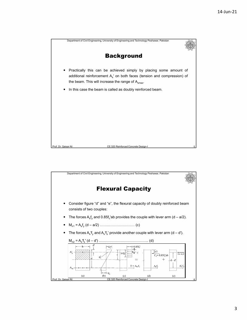
Consider figure “d” and “e”, the flexural capacity of doubly reinforced beam
consists of two couples:
The forces Asfy and 0.85fc′ab provides the couple with lever arm (d – a/2).
Mn1 = Asfy (d – a/2) ……..………………… (c)
The forces As′fy and As′fs′ provide another couple with lever arm (d – d′).
Mn2 = As′fs′ (d – d′) ………………………………….. (d)
Flexural Capacity
C

14-Jun-21
4
Department of Civil Engineering, University of Engineering and Technology Peshawar, Pakistan
Prof. Dr. Qaisar Ali CE:320 Reinforced Concrete Design-I 7
Flexural Capacity
CCC
The total nominal capacity of doubly reinforced beam is therefore,
Mn = Mn1 + Mn2 = Asfy (d – a/2) + As′fs′ (d – d′)
Department of Civil Engineering, University of Engineering and Technology Peshawar, Pakistan
Prof. Dr. Qaisar Ali CE:320 Reinforced Concrete Design-I 8
Flexural Capacity
Factored flexural capacity is given as,
ΦMn = ΦAsfy (d – a/2) + ΦAs′fs′ (d – d′) …………….. (e)
To avoid failure, ΦMn ≥ Mu. For ΦMn = Mu, we have from equation (e),
Mu = ΦAsfy (d – a/2) + ΦAs′fs′ (d – d′) ……………..… (f)
Where, ΦAsfy (d – a/2) is equal to ΦMnmax (singly) for As = Asmax
Therefore, Mu = ΦMnmax (singly) + ΦAs′fs′ (d – d′)
{Mu – ΦMnmax (singly)} = ΦAs′fs′ (d – d′) (Mu – ΦMnmax (singly)= Mu(extra))
As′ = {Mu(extra)} / {Φfs′ (d – d′)} ……….….... (g) ; where, fs′ ≤ fy

14-Jun-21
5
Department of Civil Engineering, University of Engineering and Technology Peshawar, Pakistan
Prof. Dr. Qaisar Ali CE:320 Reinforced Concrete Design-I 9
Conditions at which fs′ = fy ; Compression steel yields.
By similarity of triangle (fig b), compression steel strain
(εs′) is, εs′ = εu (c – d′)/ c ….. (h)
For tensile steel strain (εs) = εt =εty + 0.003 (for under reinforced behavior):
c = 0.41d for fy = 40 ksi, c = 0.37d for fy = 60 ksi
Substituting the value of c and εu = 0.003 in eqn. (h), we get,
εs′ = (0.003 – 0.0073d′/d) for fy=40 ksi, εs′ = (0.003 – 0.008d′/d) for fy=60 ksi…(i)
Equation (i) gives the value of εs′ for the condition at which reinforcement on
tension side is at strain of εty + 0.003, ensuring ductility.
Flexural Capacity
Department of Civil Engineering, University of Engineering and Technology Peshawar, Pakistan
Prof. Dr. Qaisar Ali CE:320 Reinforced Concrete Design-I 10
Conditions at which fs′ = fy ; Compression steel yields.
εs′ = (0.003 – 0.0073d′/d) for fy=40 ksi, εs′ = (0.003 – 0.008d′/d) for fy=60 ksi...(i)
OR
d′/d = (0.003 - εs′)/0.0073 for (40 ksi) and d′/d = (0.003 - εs′)/0.008 for (60 ksi)..(j)
Substituting εs′ = εy,in equation (j).
d′/d = (0.003 - εy)/0.0073 for (40 ksi) and d′/d = (0.003 - εy)/0.008 for (60 ksi)...(k)
Equation (k) gives the value of d′/d that ensures that when tension steel is at a
strain of εty + 0.003 (ensuring ductility), the compression steel will also be at
yield.
Therefore for compression to yield, d′/d should be less than the value given by
equation (k).
Flexural Capacity
14-Jun-21
6
Department of Civil Engineering, University of Engineering and Technology Peshawar, Pakistan
Prof. Dr. Qaisar Ali CE:320 Reinforced Concrete Design-I 11
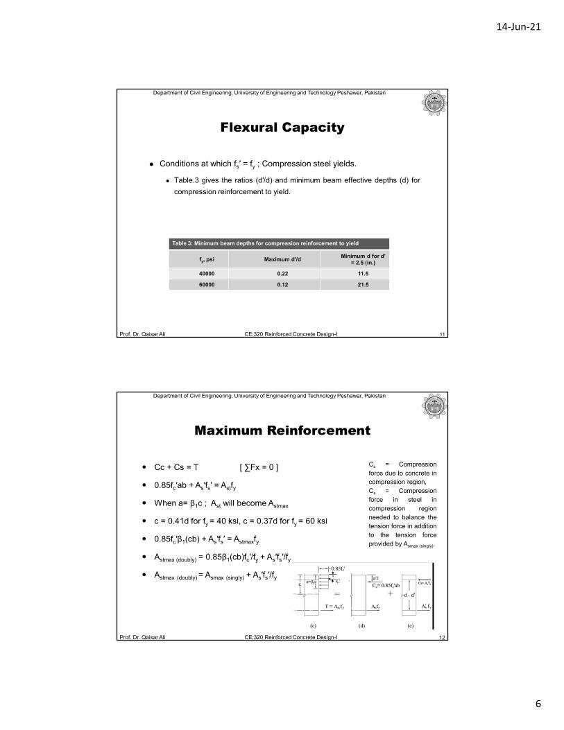
Conditions at which fs′ = fy ; Compression steel yields.
Table.3 gives the ratios (d′/d) and minimum beam effective depths (d) for
compression reinforcement to yield.
Table 3: Minimum beam depths for compression reinforcement to yield
fy, psi Maximum d'/dMinimum d for d'
= 2.5 (in.)
40000 0.22 11.5
60000 0.12 21.5
Flexural Capacity
Department of Civil Engineering, University of Engineering and Technology Peshawar, Pakistan
Prof. Dr. Qaisar Ali CE:320 Reinforced Concrete Design-I 12
Cc + Cs = T [ ∑Fx = 0 ]
0.85fc′ab + As′fs′ = Astfy
When a= β1c ; Ast will become Astmax
c = 0.41d for fy = 40 ksi, c = 0.37d for fy = 60 ksi
0.85fc′β1(cb) + As′fs′ = Astmaxfy
Astmax (doubly) = 0.85β1(cb)fc′/fy + As′fs′/fy
Astmax (doubly) = Asmax (singly) + As′fs′/fy
Maximum Reinforcement
Cc = Compression
force due to concrete in
compression region,
Cs = Compression
force in steel in
compression region
needed to balance the
tension force in addition
to the tension force
provided by Asmax (singly).
CCC
14-Jun-21
7
Department of Civil Engineering, University of Engineering and Technology Peshawar, Pakistan
Prof. Dr. Qaisar Ali CE:320 Reinforced Concrete Design-I 13
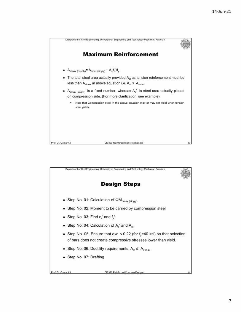
Astmax (doubly)= Asmax (singly) + As′fs′/fy
The total steel area actually provided Ast as tension reinforcement must be
less than Astmax in above equation i.e. Ast ≤ Astmax
Astmax (singly ) is a fixed number, whereas As′ is steel area actually placed
on compression side. (For more clarification, see example)
Note that Compression steel in the above equation may or may not yield when tension
steel yields.
Maximum Reinforcement
Department of Civil Engineering, University of Engineering and Technology Peshawar, Pakistan
Prof. Dr. Qaisar Ali CE:320 Reinforced Concrete Design-I 14
Step No. 01: Calculation of ΦMnmax (singly)
Step No. 02: Moment to be carried by compression steel
Step No. 03: Find εs′ and fs′
Step No. 04: Calculation of As′ and Ast.
Step No. 05: Ensure that d′/d < 0.22 (for fy=40 ksi) so that selection
of bars does not create compressive stresses lower than yield.
Step No. 06: Ductility requirements: Ast ≤ Astmax
Step No. 07: Drafting
Design Steps
14-Jun-21
8
Department of Civil Engineering, University of Engineering and Technology Peshawar, Pakistan
Prof. Dr. Qaisar Ali CE:320 Reinforced Concrete Design-I 15
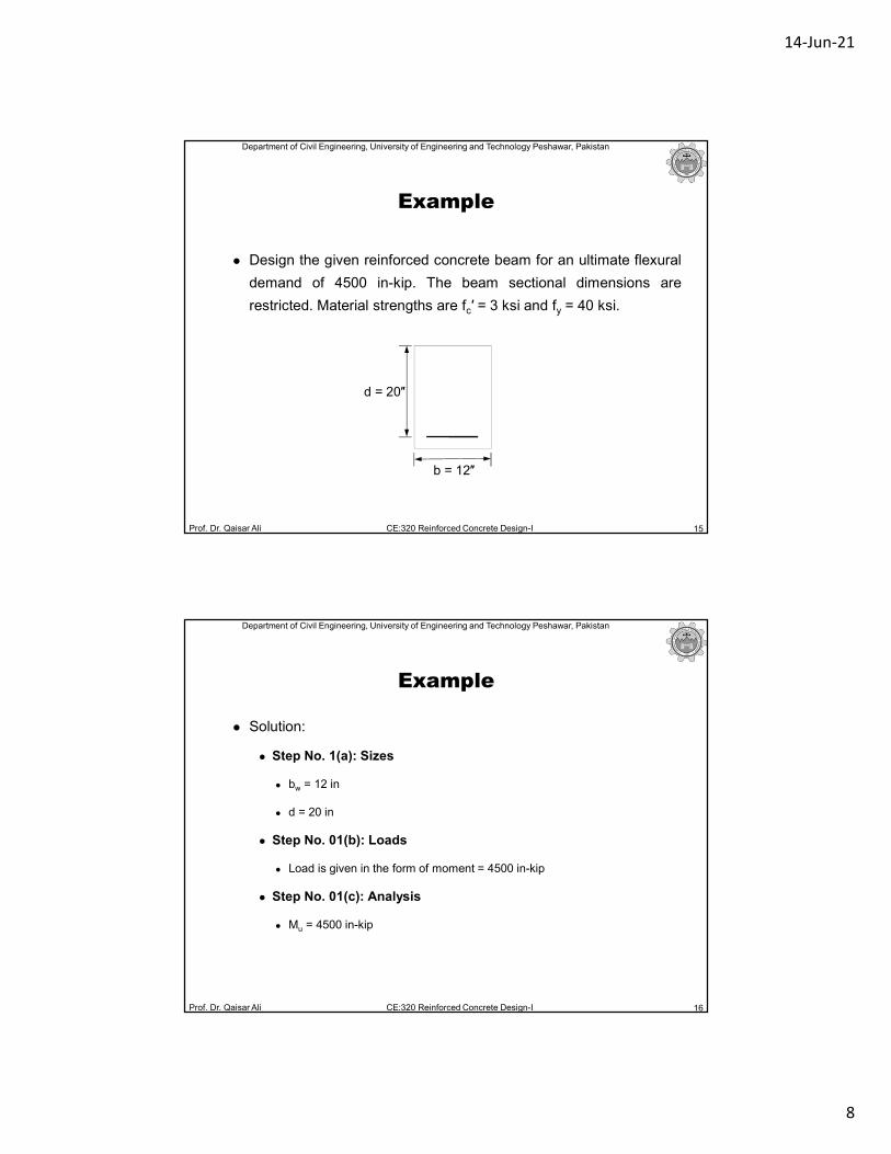
Design the given reinforced concrete beam for an ultimate flexural
demand of 4500 in-kip. The beam sectional dimensions are
restricted. Material strengths are fc′ = 3 ksi and fy = 40 ksi.
Example
d = 20″
b = 12″
Department of Civil Engineering, University of Engineering and Technology Peshawar, Pakistan
Prof. Dr. Qaisar Ali CE:320 Reinforced Concrete Design-I 16
Solution:
Step No. 1(a): Sizes
bw = 12 in
d = 20 in
Step No. 01(b): Loads
Load is given in the form of moment = 4500 in-kip
Step No. 01(c): Analysis
Mu = 4500 in-kip
Example

14-Jun-21
9
Department of Civil Engineering, University of Engineering and Technology Peshawar, Pakistan
Prof. Dr. Qaisar Ali CE:320 Reinforced Concrete Design-I 17
Solution:
Step No. 01(d): Design
ΦMn ≥ Mu (ΦMn is Mdesign or Mcapacity)
For ΦMn = Mu
ΦAsfy(d – a/2) = Mu
As = Mu/ {Φfy (d – a/2)}
Calculate “As” by trial and success method.
As= 8.75 in2
Example
Department of Civil Engineering, University of Engineering and Technology Peshawar, Pakistan
Prof. Dr. Qaisar Ali CE:320 Reinforced Concrete Design-I 18
Solution:
Step No. 01(d): Design
After trials As comes out to be 8.75 in2
Asmax= 0.3 x fc′/fy bwx d = 0.3x 3/40 x 12 x 20= 5.4 in2
As As= 8.75 in2 > Asmax = 5.4 in2 the given beam can’t be designed as a
singly reinforced beam because ACI 318 code does not allow to use As
greater than Asmax .
Now designing the beam as a doubly reinforced beam.
Example
14-Jun-21
10
Department of Civil Engineering, University of Engineering and Technology Peshawar, Pakistan
Prof. Dr. Qaisar Ali CE:320 Reinforced Concrete Design-I 19
Solution:
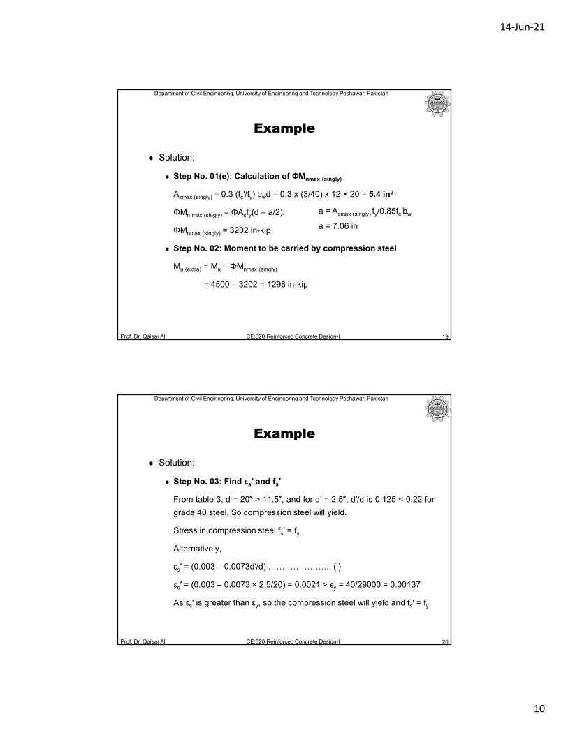
Step No. 01(e): Calculation of ΦMnmax (singly)
Asmax (singly) = 0.3 (fc′/fy) bwd = 0.3 x (3/40) x 12 × 20 = 5.4 in2
ΦMn max (singly) = ΦAsfy(d – a/2),
ΦMnmax (singly) = 3202 in-kip
Step No. 02: Moment to be carried by compression steel
Mu (extra) = Mu – ΦMnmax (singly)
= 4500 – 3202 = 1298 in-kip
Example
a = Asmax (singly) fy/0.85fc′bw
a = 7.06 in
Department of Civil Engineering, University of Engineering and Technology Peshawar, Pakistan
Prof. Dr. Qaisar Ali CE:320 Reinforced Concrete Design-I 20
Solution:
Step No. 03: Find εs′ and fs′
From table 3, d = 20″ > 11.5″, and for d′ = 2.5″, d′/d is 0.125 < 0.22 for
grade 40 steel. So compression steel will yield.
Stress in compression steel fs′ = fy
Alternatively,
εs′ = (0.003 – 0.0073d′/d) ………………….. (i)
εs′ = (0.003 – 0.0073 × 2.5/20) = 0.0021 > εy = 40/29000 = 0.00137
As εs′ is greater than εy, so the compression steel will yield and fs′ = fy
Example
14-Jun-21
11
Department of Civil Engineering, University of Engineering and Technology Peshawar, Pakistan
Prof. Dr. Qaisar Ali CE:320 Reinforced Concrete Design-I 21
Solution:
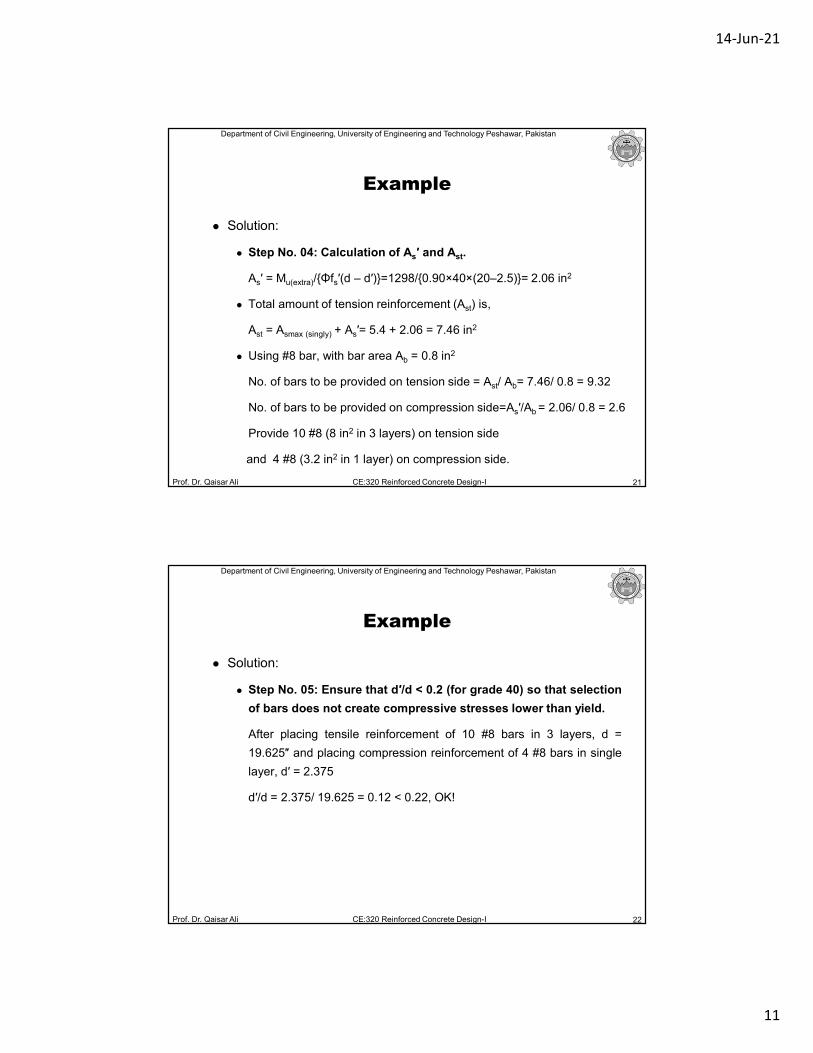
Step No. 04: Calculation of As′ and Ast.
As′ = Mu(extra)/{Φfs′(d – d′)}=1298/{0.90×40×(20–2.5)}= 2.06 in2
Total amount of tension reinforcement (Ast) is,
Ast = Asmax (singly) + As′= 5.4 + 2.06 = 7.46 in2
Using #8 bar, with bar area Ab = 0.8 in2
No. of bars to be provided on tension side = Ast/ Ab= 7.46/ 0.8 = 9.32
No. of bars to be provided on compression side=As′/Ab = 2.06/ 0.8 = 2.6
Provide 10 #8 (8 in2 in 3 layers) on tension side
and 4 #8 (3.2 in2 in 1 layer) on compression side.
Example
Department of Civil Engineering, University of Engineering and Technology Peshawar, Pakistan
Prof. Dr. Qaisar Ali CE:320 Reinforced Concrete Design-I 22
Solution:
Step No. 05: Ensure that d′/d < 0.2 (for grade 40) so that selection
of bars does not create compressive stresses lower than yield.
After placing tensile reinforcement of 10 #8 bars in 3 layers, d =
19.625″ and placing compression reinforcement of 4 #8 bars in single
layer, d′ = 2.375
d′/d = 2.375/ 19.625 = 0.12 < 0.22, OK!
Example
14-Jun-21
12
Department of Civil Engineering, University of Engineering and Technology Peshawar, Pakistan
Prof. Dr. Qaisar Ali CE:320 Reinforced Concrete Design-I 23
Solution:
Step No. 06: Ductility requirements: Ast ≤ Astmax
Ast , which is the total steel area actually provided as tension
reinforcement must be less than Astmax .
Astmax (doubly)= Asmax (singly) + As′fs′/fy
Astmax (singly ) is a fixed number for the case under consideration and
As′ is steel area actually placed on compression side.
Asmax (singly) = 5.4 in2 ; As′ = 4 × 0.8 = 3.2 in2
Astmax (doubly)= 5.4 + 3.2 = 8.6 in2
Ast = 8 in2
Therefore Ast = 8 in2 < Astmax(doubly) OK.
Example
Department of Civil Engineering, University of Engineering and Technology Peshawar, Pakistan
Prof. Dr. Qaisar Ali CE:320 Reinforced Concrete Design-I 24
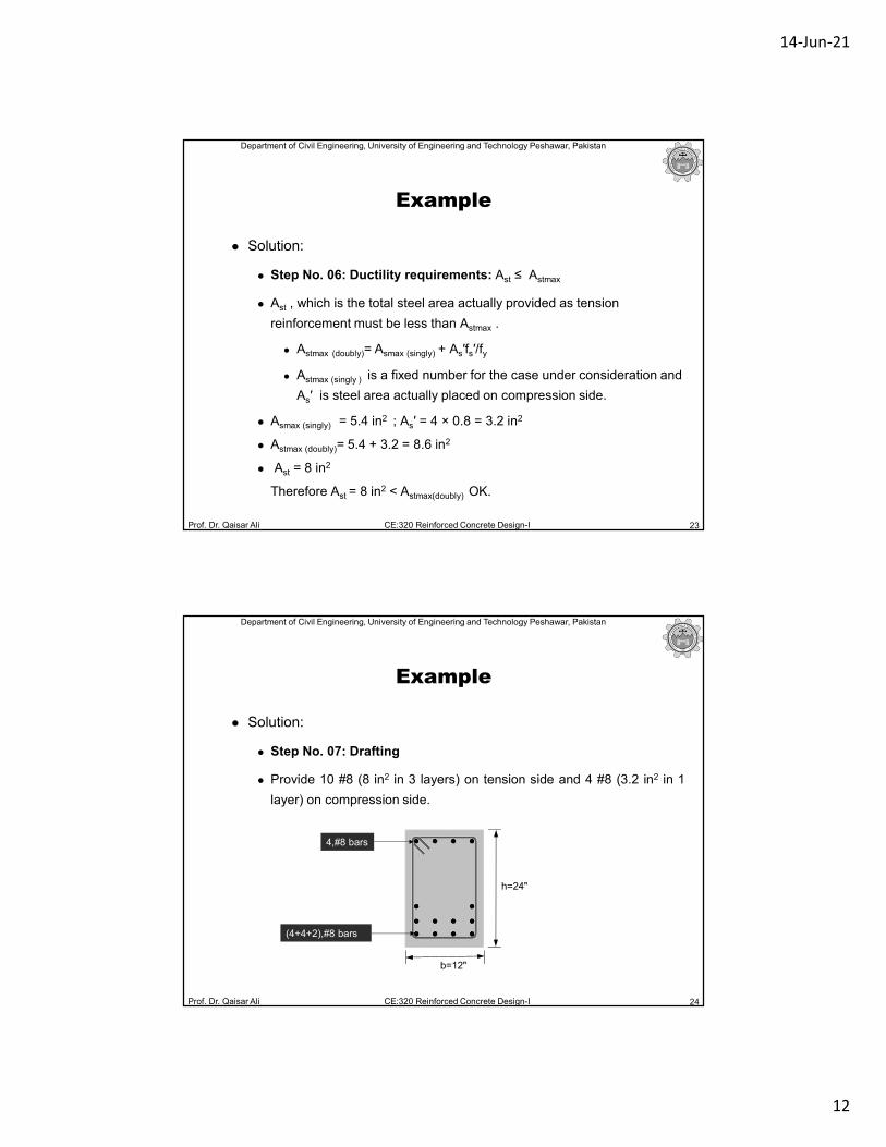
Solution:
Step No. 07: Drafting
Provide 10 #8 (8 in2 in 3 layers) on tension side and 4 #8 (3.2 in2 in 1
layer) on compression side.
Example
(4+4+2),#8 bars
4,#8 bars
b=12"
h=24"
14-Jun-21
13
Department of Civil Engineering, University of Engineering and Technology Peshawar, Pakistan
Prof. Dr. Qaisar Ali CE:320 Reinforced Concrete Design-I
Design of Concrete Structures 14th Ed. by Nilson, Darwin and
Dolan.
Building Code Requirements for Structural Concrete (ACI 318-19)
25
References
Related Documents


