processes Article Design of Cyclone Separator Critical Diameter Model Based on Machine Learning and CFD Donggeun Park 1 and Jeung Sang Go 2, * 1 Department of Advanced Materials and Parts of Transportation Systems, Pusan National University, Busan 46241, Korea; [email protected] 2 School of Mechanical Engineering, Pusan National University, Busan 46241, Korea * Correspondence: [email protected] Received: 3 November 2020; Accepted: 21 November 2020; Published: 23 November 2020 Abstract: In this paper, the characteristics of the cyclone separator was analyzed from the Lagrangian perspective for designing the important dependent variables. The neural network network model was developed for predicting the separation performance parameter. Further, the predictive performances were compared between the traditional surrogate model and the developed neural network model. In order to design the important parameters of the cyclone separator based on the particle separation theory, the force acting until the particles are separated was calculated using the Lagrangian-based computational fluid dynamics (CFD) methodology. As a result, it was proved that the centrifugal force and drag acting on the critical diameter having a separation efficiency of 50% were similar, and the particle separation phenomenon in the cyclone occurred from the critical diameter, and it was set as an important dependent variable. For developing a critical diameter prediction model based on machine learning and multiple regression methods, unsteady-Reynolds averaged Navier-Stokes analyzes according to shape dimensions were performed. The input design variables for predicting the critical diameter were selected as four geometry parameters that affect the turbulent flow inside the cyclone. As a result of comparing the model prediction performances, the machine learning (ML) model, which takes into account the critical diameter and the nonlinear relationship of cyclone design variables, showed a 32.5% improvement in R-square compared to multi linear regression (MLR). The proposed techniques have proven to be fast and practical tools for cyclone design. Keywords: cyclone separator; computational fluid dynamics (CFD); machine learning; unsteady RANS; critical diameter 1. Introduction Cyclone separators with cheap and high separation performance have been mainly used to reduce the emissions from industrial and manufacturing processes. The cyclone separates the contaminant particles by the turbulence flow. The cyclone flows have the outer flow and inner flow. The outer flow rotates along the wall to the bottom of the dust container and an inner flow is reversed at the end of the dust container and discharged to the cyclone outlet as shown Figure 1. The centrifugal force pushes the particle to the wall (the outer flow region) and the drag force pushes the particle to the cyclone center (inner flow region). In other words, when the centrifugal force acting on the particles is greater than the drag force, the particles are trapped into the cyclone duct container. In order to increase the separation performance of the cyclone, it is necessary to design the cyclone shape so that the centrifugal force acts more than the drag force on the particles with the smallest diameter possible. The turbulent behavior of cyclone is primarily influence by the size of the cyclone shape. Processes 2020, 8, 1521; doi:10.3390/pr8111521 www.mdpi.com/journal/processes

Welcome message from author
This document is posted to help you gain knowledge. Please leave a comment to let me know what you think about it! Share it to your friends and learn new things together.
Transcript
processes
Article
Design of Cyclone Separator Critical Diameter ModelBased on Machine Learning and CFD
Donggeun Park 1 and Jeung Sang Go 2,*1 Department of Advanced Materials and Parts of Transportation Systems, Pusan National University,
Busan 46241, Korea; [email protected] School of Mechanical Engineering, Pusan National University, Busan 46241, Korea* Correspondence: [email protected]
Received: 3 November 2020; Accepted: 21 November 2020; Published: 23 November 2020 �����������������
Abstract: In this paper, the characteristics of the cyclone separator was analyzed from the Lagrangianperspective for designing the important dependent variables. The neural network network model wasdeveloped for predicting the separation performance parameter. Further, the predictive performanceswere compared between the traditional surrogate model and the developed neural network model.In order to design the important parameters of the cyclone separator based on the particle separationtheory, the force acting until the particles are separated was calculated using the Lagrangian-basedcomputational fluid dynamics (CFD) methodology. As a result, it was proved that the centrifugalforce and drag acting on the critical diameter having a separation efficiency of 50% were similar,and the particle separation phenomenon in the cyclone occurred from the critical diameter, and it wasset as an important dependent variable. For developing a critical diameter prediction model basedon machine learning and multiple regression methods, unsteady-Reynolds averaged Navier-Stokesanalyzes according to shape dimensions were performed. The input design variables for predictingthe critical diameter were selected as four geometry parameters that affect the turbulent flow insidethe cyclone. As a result of comparing the model prediction performances, the machine learning (ML)model, which takes into account the critical diameter and the nonlinear relationship of cyclone designvariables, showed a 32.5% improvement in R-square compared to multi linear regression (MLR). Theproposed techniques have proven to be fast and practical tools for cyclone design.
Keywords: cyclone separator; computational fluid dynamics (CFD); machine learning; unsteadyRANS; critical diameter
1. Introduction
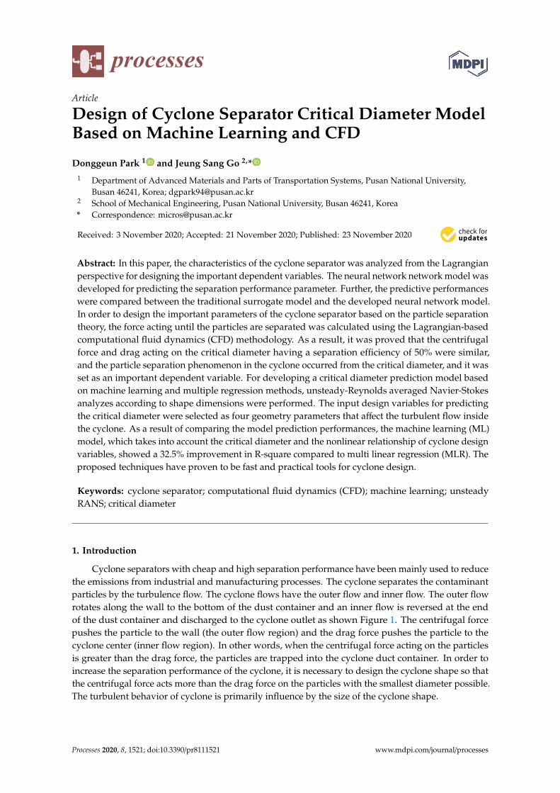
Cyclone separators with cheap and high separation performance have been mainly used to reducethe emissions from industrial and manufacturing processes. The cyclone separates the contaminantparticles by the turbulence flow. The cyclone flows have the outer flow and inner flow. The outer flowrotates along the wall to the bottom of the dust container and an inner flow is reversed at the endof the dust container and discharged to the cyclone outlet as shown Figure 1. The centrifugal forcepushes the particle to the wall (the outer flow region) and the drag force pushes the particle to thecyclone center (inner flow region). In other words, when the centrifugal force acting on the particlesis greater than the drag force, the particles are trapped into the cyclone duct container. In order toincrease the separation performance of the cyclone, it is necessary to design the cyclone shape so thatthe centrifugal force acts more than the drag force on the particles with the smallest diameter possible.The turbulent behavior of cyclone is primarily influence by the size of the cyclone shape.
Processes 2020, 8, 1521; doi:10.3390/pr8111521 www.mdpi.com/journal/processes
Processes 2020, 8, 1521 2 of 13
Figure 1. Geometry of the cyclone separator.
Therefore, many studies have been conducted over the past decades to optimize the separationperformance according to the shape of the cyclone. Early researchers developed an empirical equationbased on the experimental results about the particle separation changing the various cyclone shapeand the equation derived by the physic law [1–3]. However, since the empirical equations are based onexperimental values with uncertainty, the reproducibility of the results is poor.
With the rapid development of computing speed and numerical analysis techniques, many studieswere conducted to predict cyclone flow by solving Reynolds averaged Navier–Stokes equations basedon commercial computational fluid dynamic (CFD) codes. The CFD studies have investigated the effecton separation performance by independently setting several cyclone geometric design variables [4–10].For example, the separation efficiency and pressure drop were evaluated according to the inlet shapewithout changing other shapes by using CFD [6]. The cyclone performance investigated according tothe relationship between the cyclone outlet shape and the shape of the dust container [8,9]. Moreover,the CFD method was used to analyze the internal flow that cannot obtain the information throughexperiments. However, there is a possibility to obtain the local optimization due to considering theindependently geometric design variables. In addition, it takes a lot of computational cost to obtainthe cyclone separation performance according to various shapes by using CFD.
In order to solve the local optimization problem and computing cost problem, the methodcombining CFD and surrogate modeling has been applied for the relationship between cyclone shapesand separation performance [11–16]. For example, the surrogate models such as artificial neural network(ANN), response surface methodology (RSM) and group method of data handling (GMDH) algorithmshowed the reasonable predictive performance, and optimum design was performed by applyingoptimization algorithms such as genetic algorithms (GA) [13]. However, the most optimization studiesomitted the analysis of the cause of the optimal separation performance. For analyzing the optimizationresults, the tangential velocity contour, and the velocity distribution before and after optimizationwas compared based on the particle separation theory from Euler’s point of view [13,14]. However,since the force acting on the particles differs according to the rotational trajectory, it is more appropriateto analyze it according to the trajectory position rather than to analyze it from the Euler perspective.In other words, it is necessary to analyze the force acting according to the particle trajectory in thecyclone from the Lagrangian perspective. By analyzing the cyclone separation performance fromthe Lagrangian point of view, the verified cyclone separation performance parameter can be newlyconsidered as a dependent variable of the cyclone design.
This study has two purposes, (1) to analyze the characteristics of cyclones from the Lagrangianperspective by using CFD for designing important dependent variables that are different from previousstudies, (2) to develop a machine learning prediction model of the obtained dependent variables, and(3) to compare the prediction performance with the machine learning model and traditional surrogatemodel. This study identifies more rational dependent variables for cyclone design. In addition, it ispossible to propose a fast and reliable process.
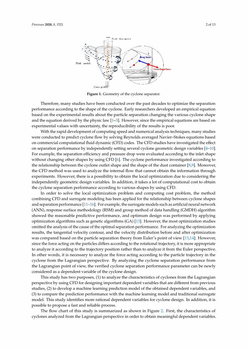
The flow chart of this study is summarized as shown in Figure 2. First, the characteristics ofcyclones analyzed from the Lagrangian perspective in order to obtain meaningful dependent variables.
Processes 2020, 8, 1521 3 of 13
Next, a CFD data set about the dependent variables is generated to develop a machine learning model.The data sets are created by a design space with various combinations using the design of experiment(DoE) method. Then, the machine learning model for cyclone separation performance are developedby the CFD data set. Finally, the developed model evaluates the predictive performance compared tothe traditional surrogate model, MLR.
Figure 2. Research flow chart.
2. Research Methods
2.1. Governing Equation for Numerical Simulation
The numerical simulation was applied to obtain the dependent variable of the separationperformance for machine learning algorithm. The cyclone flow has strong three-dimensional rotationalturbulence. For analyzing the cyclone flow, the 3D Reynolds averaged Naiver–Stokes equation aresolved based on finite volume method. The Equation (1) represents the RANS equation.
∂ui
∂t+ u j
∂ui
∂xj= −
1ρ
∂p∂xi
+∂2ui
∂xj∂xj−
∂∂xj
u′i u′
j (1)
where the p is pressure. the velocity components are decomposed into the mean velocity, ui andfluctuating velocity, u′i , respectively. The u′i is Reynolds stress. The additional process of Reynoldsstress is required to solve the RANs equation. The various turbulence models have been used for solvethe Reynolds stress term [17]. Appropriate turbulence models must be applied to obtain high-accuracynumerical analysis results. The turbulence models have been successfully applied in many industrialfields. For detailed equations and explanations on the turbulence model, reference is made to thelength limitation of this paper [17,18].
The behavior of fluid and solid particles was simulated complementarily for investigatingthe dynamic behavior of particle in cyclone. In order to design rationally the cyclone separationperformance parameters, which is one of the objectives of this study, it is necessary to track the dynamic
Processes 2020, 8, 1521 4 of 13
behavior of solid particles based on the Lagrangian method rather than the Euler method. The Equation(2) represents the particle trajectory equilibrium equation [17].
d→up
dt=
(→u k +
→u′
k −→up
)τ
+
→g (ρ p − ρ)
ρp+ F (2)
where the term(→u k+ u′k−
→u p
)τ is the drag force per unit particle mass,
→up is the particle velocity,
→u k is the
flow phase velocity, and F is an additional acceleration (force/unit particle mass). The→u′
k as the term ofturbulence transport equation influences the behavior of the particles. τ is particle relaxation time. τ isas follow in Equation (3):
τ =18µ
d2pρP
Rep
24CD (3)
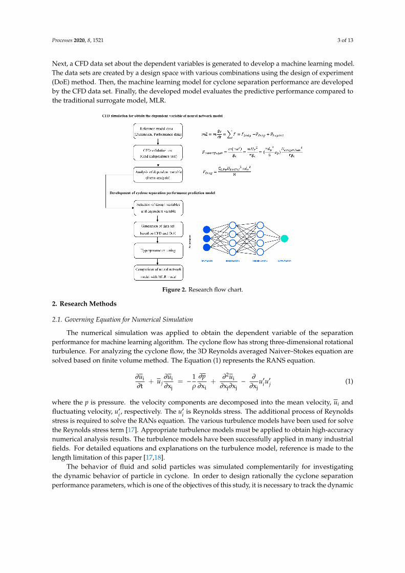
where the dP is the particle diameter, ρP is density of particle, µ is the density of fluid, Rep is theparticle Reynolds number, and CD is the drag coefficient. In this study, the commercial CFD codeANSYS 16.1 was used to solve Equations (1) and (2). The computational domain of cyclone is used asa cutcell type as shown Figure 3. The cyclone dimension of reference was cited for validating CFDresults [19]. The near-wall treatment was achieved by using scalable wall functions considering thegrid refinement with y+ < 11. The Table 1 shows the boundary conditions for numerical analysisapplied in this study. The simulation time is set as 1.5 second considering the physic time. For CFDsimulation, the SIMPLE algorithm, PRESTO! alogorithm. Second order upwind scheme were used forpressure term, pressure–velocity term, and turbulence kinetic and dissipation and momentum term,respectively. The criteria of residual values of the turbulence equation and other equation for assessingCFD convergence were set as 10−6 and 10−4.
Figure 3. Computational domain of cyclone separators.
Table 1. Boundary condition for computational fluid dynamics (CFD).
Boundary Condition Values
Inlet velocity 800 (m3/h)Pressure drop 1 atmTime step size 0.001 s
Number of time step 1500
2.2. Machine Learning Algorithm
The CFD simulations with combinations of various geometric design variables are time consuming.A machine learning model for cyclone separation performance has been developed for solving the time
Processes 2020, 8, 1521 5 of 13
cost problem of cyclone design. The developed model can predict fast separation performance changingthe various design combinations. The separation performance model was developed using the backpropagation neural network model among machine learning algorithms. The neural network modelpredicts the output variable according to the new input variable by giving nonlinear characteristics tothe relationship between the input design variable and the output variable. The structure of the neuralnetwork consists of several hidden layers between input and output variables. The layer consists ofvarious nodes, and the node converts the linear combination of input variables into a sigmoid nonlinearform as shown in Equations (4) and (5).
y(k)j = b0 +
n∑i=1
wixi (4)
y(k)j_out
=1
1 + exp(−y(k)
j
) (5)
where k is layer number, j is node number, and wi is weight. The input variables are transferred to thehidden layer and calculated until the end of the output. Then, the weight of all nodes are updatedrepeatedly so that the error with the true value is minimized. This is called backpropagation process.That is, the parameters such as learning rate, epoch, batch size, and number of hidden layers etc. mustbe optimized to make the minimum difference value between the true value and prediction value.
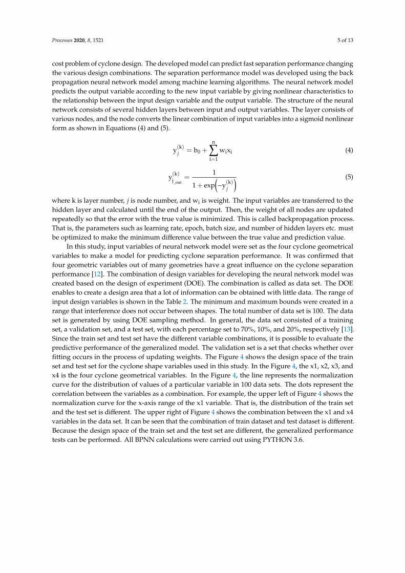
In this study, input variables of neural network model were set as the four cyclone geometricalvariables to make a model for predicting cyclone separation performance. It was confirmed thatfour geometric variables out of many geometries have a great influence on the cyclone separationperformance [12]. The combination of design variables for developing the neural network model wascreated based on the design of experiment (DOE). The combination is called as data set. The DOEenables to create a design area that a lot of information can be obtained with little data. The range ofinput design variables is shown in the Table 2. The minimum and maximum bounds were created in arange that interference does not occur between shapes. The total number of data set is 100. The dataset is generated by using DOE sampling method. In general, the data set consisted of a trainingset, a validation set, and a test set, with each percentage set to 70%, 10%, and 20%, respectively [13].Since the train set and test set have the different variable combinations, it is possible to evaluate thepredictive performance of the generalized model. The validation set is a set that checks whether overfitting occurs in the process of updating weights. The Figure 4 shows the design space of the trainset and test set for the cyclone shape variables used in this study. In the Figure 4, the x1, x2, x3, andx4 is the four cyclone geometrical variables. In the Figure 4, the line represents the normalizationcurve for the distribution of values of a particular variable in 100 data sets. The dots represent thecorrelation between the variables as a combination. For example, the upper left of Figure 4 shows thenormalization curve for the x-axis range of the x1 variable. That is, the distribution of the train setand the test set is different. The upper right of Figure 4 shows the combination between the x1 and x4variables in the data set. It can be seen that the combination of train dataset and test dataset is different.Because the design space of the train set and the test set are different, the generalized performancetests can be performed. All BPNN calculations were carried out using PYTHON 3.6.
Processes 2020, 8, 1521 6 of 13
Figure 4. Design space for dataset; x1, x2, x3, and x4 is design variable of cyclone.
Table 2. Range of design variable of cyclone.
Boundary Condition Min (x/D1) Max (x/D1)
Outlet diameter 0.275 0.475Inlet width 0.15 0.35Inlet height 0.3375 0.5375Cone length 0.5 1.95
D1 is 0.4 m.
3. Results
3.1. CFD Simulation Result for Validation
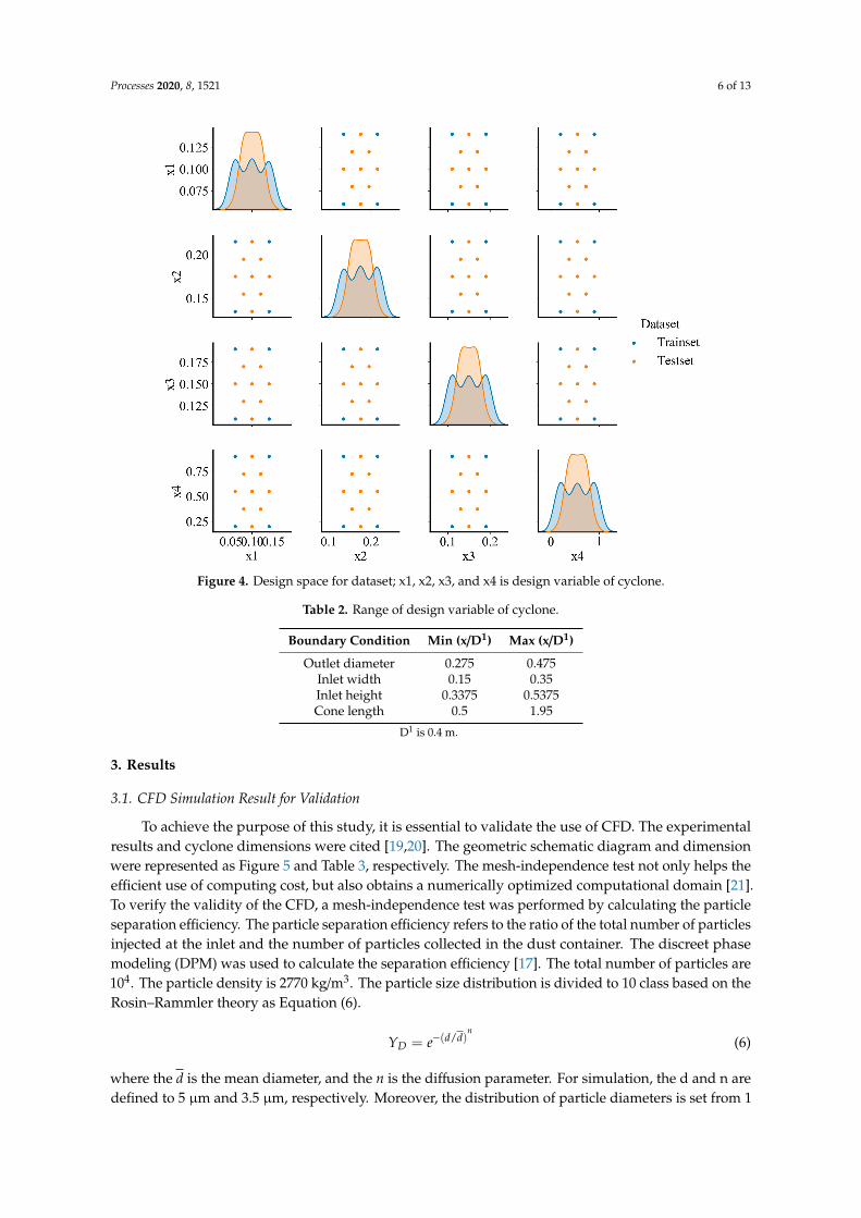
To achieve the purpose of this study, it is essential to validate the use of CFD. The experimentalresults and cyclone dimensions were cited [19,20]. The geometric schematic diagram and dimensionwere represented as Figure 5 and Table 3, respectively. The mesh-independence test not only helps theefficient use of computing cost, but also obtains a numerically optimized computational domain [21].To verify the validity of the CFD, a mesh-independence test was performed by calculating the particleseparation efficiency. The particle separation efficiency refers to the ratio of the total number of particlesinjected at the inlet and the number of particles collected in the dust container. The discreet phasemodeling (DPM) was used to calculate the separation efficiency [17]. The total number of particles are104. The particle density is 2770 kg/m3. The particle size distribution is divided to 10 class based on theRosin–Rammler theory as Equation (6).
YD = e−(d/d)n
(6)
where the d is the mean diameter, and the n is the diffusion parameter. For simulation, the d and n aredefined to 5 µm and 3.5 µm, respectively. Moreover, the distribution of particle diameters is set from 1
Processes 2020, 8, 1521 7 of 13
to 10 µm. The simulation results by decreasing mesh size were compared with the cited experimentaldata [19]. The three mesh types as coarse, fine, and finest were used for mesh-independent test.The total number and mesh size of coarse types are 5.35 × 10⁵ and 100 mm, respectively. The totalnumber and mesh size of fine types are 5.81 × 10⁶ and 6.5 mm, respectively. The total number and meshsize of coarse types are 9.58 × 10⁶ and 3.5 mm, respectively. The near-wall treatment was achievedby using scalable wall functions considering the grid refinement with y+ < 11. The growth from thewall is at a ratio of 1.5. The CFD results by three grid types were compared with the experimentaldata as Table 4. As the mesh size decreases, the numerical values converged. The error between theCFD results and the referenced experimental results was within 2%. The grid size of fine type meshwas 6.5 mm. The fine type mesh was selected due to the numeric accuracy and computational costin this study. Furthermore, the mesh quality check for the fine type mesh was performed as shownthe Table 5. The quality checking results show that the averaged skewness is 0.177 which representsthe reasonable accuracy of mesh shape and the averaged aspect ratio of the fine mesh is about 1.814.Therefore, the fine type mesh is acceptable. The selected grid size is used as an input condition of CFDanalysis for neural network modeling.
Figure 5. Geometric schematic diagram.
Table 3. Geometric parameter values.
Factors Values (x/D1)
Outlet diameter 0.375Inlet width 0.25Inlet height 0.4375Cone length 1.225
Cylinder length 1.25Vortex finder length 0.45
Tube 0.74Con-tip-diameter 0.375Collector Length 0.745
Collector diameter 0.735
D1 is 0.4 m.
Processes 2020, 8, 1521 8 of 13
Table 4. Grid dependence test results.
Mesh Type Coarse Fine Finest Exp. [19]
Separation efficiency 52.21% 84.42% 84.35% 83.5%Error with Exp. [19] 37.4% 1.101% 1.017% -
Table 5. Mesh quality check results for the fine mesh type.
Mesh Type Values
Skewness average 0.177Aspect ratio average 1.814
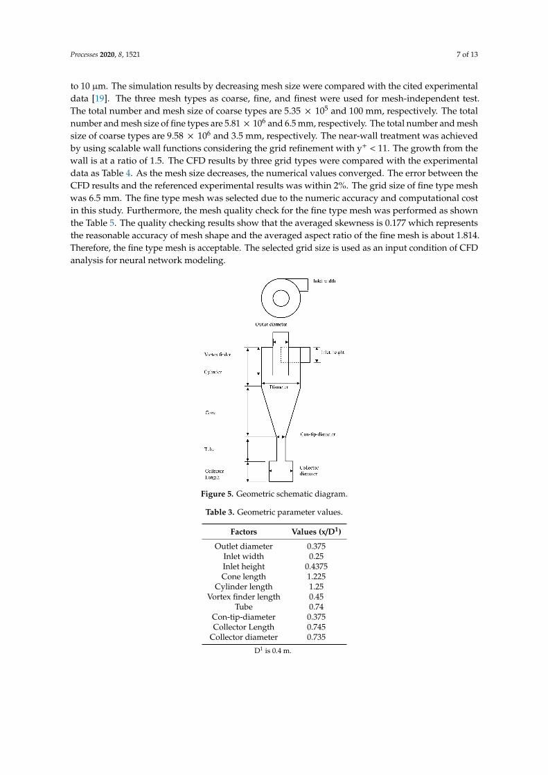
In addition, in order to select an appropriate turbulence model that can simulate a cyclone strongrotational flow, the results of the velocity distribution experiment [20] and the prediction resultsaccording to the turbulence model were compared. The experimental data and simulation data werecompared with the results of the tangential velocity and axial velocity distribution at the certainlocations (Y = 0.77D, A−A′) as shown Figure 6. The residual values of the turbulence equation andmass equation showed the under 10−6 and 10−4. In the Figure 6, the x label is the distance from thecenter of the cyclone to the wall. When the k− εmodel was used, it showed an abnormal tangentialdistribution near the wall. The reason for this prediction is that the k− εmodel assumes anisotropicproperty for modeling the Reynolds stress term. When k− εmodel is applied for cyclone flow analysis,the outer flow and inner flow can be captured incorrectly. In contrast, Reynolds stress model (RSM)predicted a velocity distribution similar to the experimental results. The RSM can properly simulaterotational flow through an isotropic assumption for Reynolds stress term. Therefore, in this study,the RSM was applied to capture the cyclone flow. The detailed equations and explanations on the RSMcan refer the reference [17,18].
Figure 6. Comparison results of the velocity distribution experiment and the prediction resultsaccording to the turbulence model.
3.2. CFD Simulation for the Dependent Variable of Cyclone
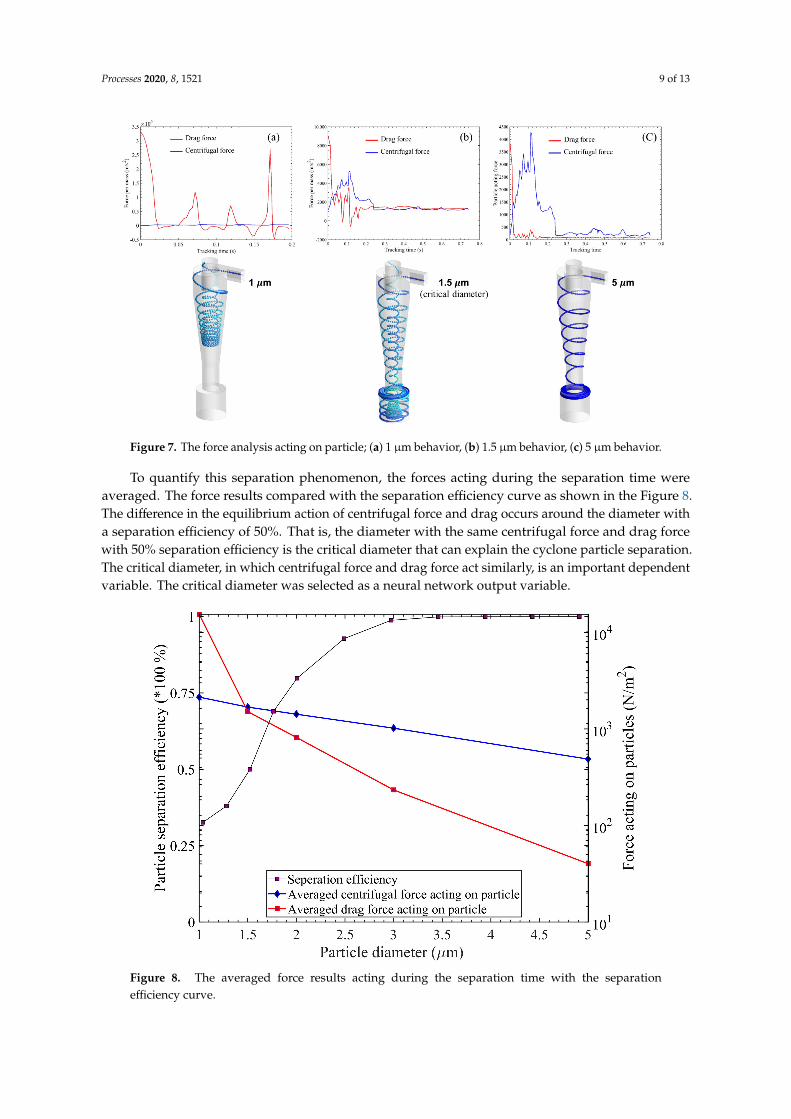
The important dependent variables were designed by analyzing the characteristics of cyclonesfrom the Lagrangian perspective. The force acting on the particles was calculated until the particleswere separated by using ANSYS FLUET User Define Function code. The dynamic behavior results arevery similar to the particle separation theory. The Figure 7 represents the force analysis results.
As shown Figure 7, In the case of 1 µm particles, the drag acting on the particles is superior to thecentrifugal force, so the particles enter the inner flow region and are discharged through the cycloneoutlet. In the case of 1.5 µm, the centrifugal force and drag act similarly, resulting in rotational motionwithin the cyclone. Eventually, the drag force is slightly larger and the particles are rebound in the dustcontainer. The 5 µm particles have a larger centrifugal force than the drag force, so that the particlesare collected in the dust container.
Processes 2020, 8, 1521 9 of 13
Figure 7. The force analysis acting on particle; (a) 1 µm behavior, (b) 1.5 µm behavior, (c) 5 µm behavior.
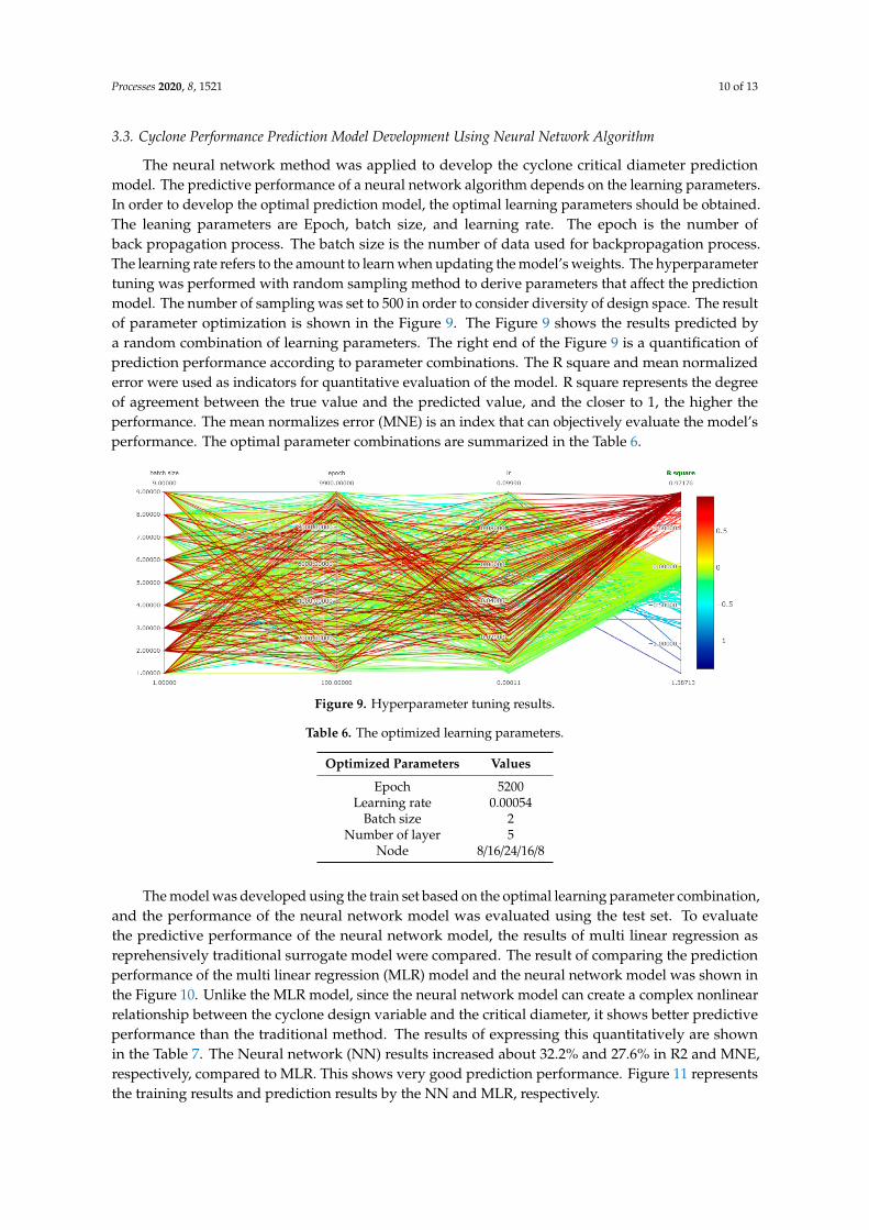
To quantify this separation phenomenon, the forces acting during the separation time wereaveraged. The force results compared with the separation efficiency curve as shown in the Figure 8.The difference in the equilibrium action of centrifugal force and drag occurs around the diameter witha separation efficiency of 50%. That is, the diameter with the same centrifugal force and drag forcewith 50% separation efficiency is the critical diameter that can explain the cyclone particle separation.The critical diameter, in which centrifugal force and drag force act similarly, is an important dependentvariable. The critical diameter was selected as a neural network output variable.
Figure 8. The averaged force results acting during the separation time with the separationefficiency curve.
Processes 2020, 8, 1521 10 of 13
3.3. Cyclone Performance Prediction Model Development Using Neural Network Algorithm
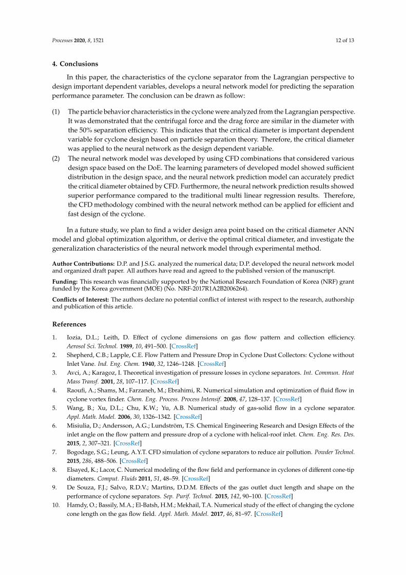
The neural network method was applied to develop the cyclone critical diameter predictionmodel. The predictive performance of a neural network algorithm depends on the learning parameters.In order to develop the optimal prediction model, the optimal learning parameters should be obtained.The leaning parameters are Epoch, batch size, and learning rate. The epoch is the number ofback propagation process. The batch size is the number of data used for backpropagation process.The learning rate refers to the amount to learn when updating the model’s weights. The hyperparametertuning was performed with random sampling method to derive parameters that affect the predictionmodel. The number of sampling was set to 500 in order to consider diversity of design space. The resultof parameter optimization is shown in the Figure 9. The Figure 9 shows the results predicted bya random combination of learning parameters. The right end of the Figure 9 is a quantification ofprediction performance according to parameter combinations. The R square and mean normalizederror were used as indicators for quantitative evaluation of the model. R square represents the degreeof agreement between the true value and the predicted value, and the closer to 1, the higher theperformance. The mean normalizes error (MNE) is an index that can objectively evaluate the model’sperformance. The optimal parameter combinations are summarized in the Table 6.
Figure 9. Hyperparameter tuning results.
Table 6. The optimized learning parameters.
Optimized Parameters Values
Epoch 5200Learning rate 0.00054
Batch size 2Number of layer 5
Node 8/16/24/16/8
The model was developed using the train set based on the optimal learning parameter combination,and the performance of the neural network model was evaluated using the test set. To evaluatethe predictive performance of the neural network model, the results of multi linear regression asreprehensively traditional surrogate model were compared. The result of comparing the predictionperformance of the multi linear regression (MLR) model and the neural network model was shown inthe Figure 10. Unlike the MLR model, since the neural network model can create a complex nonlinearrelationship between the cyclone design variable and the critical diameter, it shows better predictiveperformance than the traditional method. The results of expressing this quantitatively are shownin the Table 7. The Neural network (NN) results increased about 32.2% and 27.6% in R2 and MNE,respectively, compared to MLR. This shows very good prediction performance. Figure 11 representsthe training results and prediction results by the NN and MLR, respectively.

Processes 2020, 8, 1521 11 of 13
Figure 10. The result of comparing the prediction performance of the MLR model and the neuralnetwork model.
Figure 11. The training results and prediction results by the NN and MLR; (a) Neural network results;(b) Multi linear regression.
Table 7. Neural network prediction model performance comparing with MLR results.
Metric MLR NN Improvement
Mean normalized error 6.73 1.86 −27.6%R2 0.735 0.972 +32.2%
Processes 2020, 8, 1521 12 of 13
4. Conclusions
In this paper, the characteristics of the cyclone separator from the Lagrangian perspective todesign important dependent variables, develops a neural network model for predicting the separationperformance parameter. The conclusion can be drawn as follow:
(1) The particle behavior characteristics in the cyclone were analyzed from the Lagrangian perspective.It was demonstrated that the centrifugal force and the drag force are similar in the diameter withthe 50% separation efficiency. This indicates that the critical diameter is important dependentvariable for cyclone design based on particle separation theory. Therefore, the critical diameterwas applied to the neural network as the design dependent variable.
(2) The neural network model was developed by using CFD combinations that considered variousdesign space based on the DoE. The learning parameters of developed model showed sufficientdistribution in the design space, and the neural network prediction model can accurately predictthe critical diameter obtained by CFD. Furthermore, the neural network prediction results showedsuperior performance compared to the traditional multi linear regression results. Therefore,the CFD methodology combined with the neural network method can be applied for efficient andfast design of the cyclone.
In a future study, we plan to find a wider design area point based on the critical diameter ANNmodel and global optimization algorithm, or derive the optimal critical diameter, and investigate thegeneralization characteristics of the neural network model through experimental method.
Author Contributions: D.P. and J.S.G. analyzed the numerical data; D.P. developed the neural network modeland organized draft paper. All authors have read and agreed to the published version of the manuscript.
Funding: This research was financially supported by the National Research Foundation of Korea (NRF) grantfunded by the Korea government (MOE) (No. NRF-2017R1A2B2006264).
Conflicts of Interest: The authors declare no potential conflict of interest with respect to the research, authorshipand publication of this article.
References
1. Iozia, D.L.; Leith, D. Effect of cyclone dimensions on gas flow pattern and collection efficiency.Aerosol Sci. Technol. 1989, 10, 491–500. [CrossRef]
2. Shepherd, C.B.; Lapple, C.E. Flow Pattern and Pressure Drop in Cyclone Dust Collectors: Cyclone withoutInlet Vane. Ind. Eng. Chem. 1940, 32, 1246–1248. [CrossRef]
3. Avci, A.; Karagoz, I. Theoretical investigation of pressure losses in cyclone separators. Int. Commun. HeatMass Transf. 2001, 28, 107–117. [CrossRef]
4. Raoufi, A.; Shams, M.; Farzaneh, M.; Ebrahimi, R. Numerical simulation and optimization of fluid flow incyclone vortex finder. Chem. Eng. Process. Process Intensif. 2008, 47, 128–137. [CrossRef]
5. Wang, B.; Xu, D.L.; Chu, K.W.; Yu, A.B. Numerical study of gas-solid flow in a cyclone separator.Appl. Math. Model. 2006, 30, 1326–1342. [CrossRef]
6. Misiulia, D.; Andersson, A.G.; Lundström, T.S. Chemical Engineering Research and Design Effects of theinlet angle on the flow pattern and pressure drop of a cyclone with helical-roof inlet. Chem. Eng. Res. Des.2015, 2, 307–321. [CrossRef]
7. Bogodage, S.G.; Leung, A.Y.T. CFD simulation of cyclone separators to reduce air pollution. Powder Technol.2015, 286, 488–506. [CrossRef]
8. Elsayed, K.; Lacor, C. Numerical modeling of the flow field and performance in cyclones of different cone-tipdiameters. Comput. Fluids 2011, 51, 48–59. [CrossRef]
9. De Souza, F.J.; Salvo, R.D.V.; Martins, D.D.M. Effects of the gas outlet duct length and shape on theperformance of cyclone separators. Sep. Purif. Technol. 2015, 142, 90–100. [CrossRef]
10. Hamdy, O.; Bassily, M.A.; El-Batsh, H.M.; Mekhail, T.A. Numerical study of the effect of changing the cyclonecone length on the gas flow field. Appl. Math. Model. 2017, 46, 81–97. [CrossRef]
Processes 2020, 8, 1521 13 of 13
11. Elsayed, K.; Lacor, C. Modeling and Pareto optimization of gas cyclone separator performance using RBFtype artificial neural networks and genetic algorithms. Powder Technol. 2012, 217, 84–99. [CrossRef]
12. Safikhani, H. Modeling and multi-objective Pareto optimization of new cyclone separators using CFD,ANNs and NSGA II algorithm. Adv. Powder Technol. 2016, 27, 2277–2284. [CrossRef]
13. Park, D.; Cha, J.; Kim, M.; Go, J.S. Multi-objective optimization and comparison of surrogatemodels for separation performances of cyclone separator based on CFD, RSM, GMDH-neural network,back propagation-ANN and genetic algorithm. Eng. Appl. Comput. Fluid Mech. 2020, 14, 180–201. [CrossRef]
14. Sun, X.; Kim, S.; Yang, S.D.; Kim, H.S.; Yoon, J.Y. Multi-objective optimization of a Stairmand cycloneseparator using response surface methodology and computational fluid dynamics. Powder Technol. 2017, 320,51–65. [CrossRef]
15. Safikhani, H.; Hajiloo, A.; Ranjbar, M.A. Modeling and multi-objective optimization of cyclone separatorsusing CFD and genetic algorithms. Comput. Chem. Eng. 2011, 35, 1064–1071. [CrossRef]
16. Elsayed, K.; Lacor, C. CFD modeling and multi-objective optimization of cyclone geometry using desirabilityfunction, Artificial neural networks and genetic algorithms. Appl. Math. Model. 2013, 37, 5680–5704.[CrossRef]
17. ANSYS Inc. ANSYS FLUENT Theory Guide; ANSYS FLUENT-16.1; ANSYS Inc.: Canonsburg, PA, USA, 2018.18. Tang, Y.; Guo, B.; Ranjan, D. Numerical simulation of aerosol deposition from turbulent flows using
three-dimensional RANS and les turbulence models. Eng. Appl. Comput. Fluid Mech. 2015, 9, 174–186.[CrossRef]
19. Obermair, S.; Woisetschläger, J.; Staudinger, G. Investigation of the flow pattern in different dust outletgeometries of a gas cyclone by laser Doppler anemometry. Powder Technol. 2003, 138, 239–251. [CrossRef]
20. Obermair, S.; Staudinger, G. The dust outlet of a gas cyclone and its effects on separation efficiency. Chem.Eng. Technol. 2001, 24, 1259–1263. [CrossRef]
21. Siddique, W.; El-Gabry, L.; Shevchuk, I.V.; Fransson, T.H. Validation and Analysis of Numerical Results for aTwo-Pass Trapezoidal Channel With Different Cooling Configurations of Trailing Edge. J. Turbomach. 2012,135, 1–8. [CrossRef]
Publisher’s Note: MDPI stays neutral with regard to jurisdictional claims in published maps and institutionalaffiliations.
© 2020 by the authors. Licensee MDPI, Basel, Switzerland. This article is an open accessarticle distributed under the terms and conditions of the Creative Commons Attribution(CC BY) license (http://creativecommons.org/licenses/by/4.0/).
Related Documents


![Cyclone - Progepi · b. Cyclone diameter [from 0.01 to 3 m] c. Cut diameter [from 0.2 to 20 μm] d. Cyclone efficiency [from 0 to 100%] e. Pressure drop [from 10 to 1 000 Pa] - Cyclone](https://static.cupdf.com/doc/110x72/5f557a33485e9871c8370958/cyclone-progepi-b-cyclone-diameter-from-001-to-3-m-c-cut-diameter-from-02.jpg)

